trace-orthogonal ppm-space time block coding …hulk.bu.edu/pubs/papers/2014/tr-2014-12-23.pdf ·...
TRANSCRIPT

Trace-Orthogonal PPM-Space Time Block Codingunder Rate Constraints for Visible Light Communication∗
M. Biagi, A.M. Vegni, S. Pergoloni, P. Butala, and T.D.C. Little†
December 23, 2014
MCL Technical Report No. 12-23-2014
Abstract–Visible Light Communications (VLC) represents a new frontier of communications al-lowing high data-rate Internet access, specially in indoor environments, where the use of LightEmitting Diodes (LEDs) is growing as a viable alternative to traditional illumination. As a re-sult, LED output intensity can be varied faster than human eye can perceive, thus guaranteeingsimultaneous wireless communications and illumination. One of the key challenges is the limitedmodulation bandwidth of sources that is typically around several MHz. The use of Multiple Inputand Multiple Output (MIMO) techniques in optical wireless system helps to increase the capacityof the system and thus improve the system performance. In this paper we investigate the use ofan optical MIMO technique jointly with Pulse Position Modulation in order to improve the datarates without reducing the reliability of the link. PPM is known to be Signal-to-Noise Ratio effi-cient modulation format, while it is bandwidth inefficient so the use of MIMO can compensate thatdrawback with reasonable complexity. Furthermore, an off-line tool for VLC system planning,including error probability and transmission rate, has been proposed in order to solve the trade-off between transmission rate and error rate. Finally, several numerical results and performancecomparisons are reported.
∗In J. of Lightwave Technolgy, January 2015. This work is supported by the NSF under grant No. EEC-0812056.Any opinions, findings, and conclusions or recommendations expressed in this material are those of the author(s) anddo not necessarily reflect the views of the National Science Foundation.†M. Biagi and S. Pergoloni are with the Department of Information, Electronics and Telecommunication Engi-
neeering (DIET), University of Rome “Sapienza”, Rome, Italy, via Eudossiana 18, 00148 Rome, Italy, mauro.biagi,[email protected]. A.M. Vegni is with the Department of Engineering, COMLAB Telecommunica-tions lab, Roma TRE University, Rome, Italy, [email protected]. T.D.C. Little and P. Butala are with theDepartment of Electrical and Computer Engineering, Boston University, Boston, MA USA tdcl, [email protected].
1
1 Introduction and goalsRecently, the scientific community has paid significant attention to Visible Light Communications(VLC) systems, since the idea of using the same light source for illumination, as well as to providewireless connectivity, may allow a more flexible way to access the Internet, and makes simplehardware installation [1, 2].
In this “dual-use” paradigm, VLC offers several advantages that make it a great complementto the well-established Radio-Frequency (RF) communications. Among the main advantages be-longing to VLC, we cite (i) the free use of the visible light spectrum, (ii) the directional nature ofoptical transmissions allowing coexistence of many non-interfering links in close proximity, and(iii) the secure indoor transmission. These features enable greater data rate densities [Mbit/s/m2],as well as improved security, compared to traditional RF systems [3].
In contrast to optical communications in the Infrared (IR) and Ultraviolet (UV) wavelengths,VLC is safer to human eyes, because intense visible light triggers the blinking reflex, preventingprolonged exposures. Much higher transmission powers are then allowed by eye safety regula-tions [4]; as a result, the ubiquity and the high illumination levels required for indoor lightingbodes well for VLC to provide area coverage and link robustness at high receive powers, even inabsence of Line-of-Sight (LOS) links.
Bandwidth-efficient encoding schemes, such as Pulse Amplitude Modulation (PAM) and Quadra-ture Amplitude Modulation (QAM), are also used to increase data rate, assuming that a higherrequirement for signal power is met. These have been combined with Discrete Multi-Tone (DMT)modulation to reach data rates of more than 800 Mbit/s in the lab [5, 6].The main drawback of bandwidth-efficient modulation schemes and multi-carrier schemes such asDMT is power inefficiency. This inefficiency is twofold. First, the QAM-like modulations loadedon sub-carriers are power inefficient, and second there is the requirement of additional energy tomap the constellation in the first quadrant, and so a bias light is needed. Even if in the literaturesome schemes proposed an interesting modified version of DMT reducing the bias requested forenabling transmission (see [7] and [8]), they well perform under the assumption of Additive WhiteGaussian Noise (AWGN) environment without taking care of path-loss (that in general reduces thedistance among symbols) and, more, these contributions do not solve the lack of power efficiencytypical of QAM modulations operated on OFDM sub-carriers.A way to improve system performance may be the use of diversity. This requires the knowl-edge of how many and which LEDs are able to serve an end-user especially in large rooms; as aconsequence, information about positioning is mandatory. However, having a module for trans-mission/reception and one for positioning can be costly. This strongly motivates the use of on-offschemes, such as Non-Return-to-Zero or Pulse Position Modulation (PPM) for VLC, since it can beused both for positioning and transmission. Moreover, in this contribution we consider only down-link transmission even if, it is reasnable that in the near future also optical wireless uplink will beconsidered. Hence it is expected a grow of the need of power efficient modulation formats [9, 10].Finally, PPM transmission can be helpful for localization by using the same transmitter controller(see [11]), and it is interesting to evaluate how this Signal-to-Noise Ratio (SNR)-efficient1 modu-lation can be stressed in terms of transmission rate.
1We use the term SNR-efficient to indicate that an orthogonal modulation, as PPM, requires lower SNR for anassigned error rate when the number of symbols of PPM increases.
2

1.1 Related WorkIn indoor environments, illumination is typically provided by arrays of “white” LEDs working assources that can provide sufficient light to achieve an illumination of [400–800] lux at the height ofa table [12]. In such systems, high power levels are available for communication, leading to veryhigh SNR channels [13] as compared to traditional IR free space communications. However, when’white’ phosohor-converted LEDs are used, the modulation bandwidth is limited to several MHz,due to the slow response time of the yellow phosphor that is used to generate part of the white lightspectrum.
For implementation simplicity and cost, Optical Wireless (OW) systems for indoor use willemploy single-element transmitters and receivers. However, the adoption of MIMO solutions havethe potential to substantially improve capacity by the use of laser and photodiode arrays so thatincoming data is parallelized and transmitted over multiple beams. OW MIMO links require spatialalignment among the transmitter and receiver arrays in order to avoid interference between thechannels or techniques to subsequently resolve signal overlap at the receiver. On the other hand,in OW MIMO link, a Spatial-Light Modulator (SLM) can be implemented as a transmitter, and anarray of optical intensity receivers as a single receiver, so that data is sent by creating a series oftwo-dimensional optical intensity images (see [14]).
MIMO techniques are largely used in radio communications [15], where scattering and interfer-ence create channels decorrelated from each another. This allows MIMO channels having highercapacity than the Single Input Single Output (SISO) scheme. The availability of a large num-ber of high SNR channels with low bandwidth makes MIMO techniques an attractive solution forachieving high data rates, resulting in data transmissions in parallel between multiple sources andmultiple receivers. In this regard, in [16] a MIMO VLC system architecture has been proposed,with the aim of maximizing capacity, while maintaining illumination requirements.
The use of MIMO together with a space-time coding technique can provide large gains in spec-tral efficiency. For instance, reference [17] combines Orthogonal Frequency Division Modulation(OFDM) with Spatial Modulation to provide better spectral efficiency. MIMO can highly increasethe transmission capacity of a wireless optical communication system, while not excessively in-creasing the spectral bandwidth [18]. Moreover, through the use of spatial diversity it is possibleto mitigate channel fading.
A recent trend emerging in VLC systems research is the use of organic devices i.e., organicphotodetectors (OPD), and organic LEDs (OLEDs) [19]. Organic small molecules and polymerphotonic devices are the focus of wide ranging research due to fascinating characteristics such asmechanical flexibility, and very low cost solution-based processing. Moreover, the use of organicdevices in VLC systems promises high luminous efficacies of 100 lm/W, which are into line withtraditional white LED luminous efficacies (i.e., around 120 lm/W). In [20] Haigh et al. presentan experimental demonstration of a MIMO VLC system comprised of four silicon (Si)-LEDs andfour OPDs using On-Off Keying (OOK) modulation format that can reach a data rate of 200 kb/swithout the need for equalization. Then, through the use of an artificial neural network, which hasbeen assessed as the most effective method for reducing Inter-Symbol Interference (ISI) inducedby a communication channel, the bit rate increases to 1.8 Mb/s. In order to increase the datarate of a VLC system, Haigh et al. [21] exploit equalization techniques. They present two VLClinks comprised of (i) a (Si)-LED, and an OPD, and (ii) an OLED plus a Si-PD, and implementdigital FIR post-equalizers with and without distortion. For both systems, the bit rates achieved
3

are 750 kb/s and 550 kb/s, from a raw bandwidth of 30 kHz, and 93 kHz, respectively.Because OW signals, unlike RF, are intensity modulated and non-negative, the signal mapping
for OW must be treated differently. For shorter range systems, Jivkova et al. [22] proposed a novelMIMO approach to model an indoor system, and focused on the capacity of a MIMO system.The possibility of using MIMO transmission/reception schemes for OW systems has been alreadyintroduced in [23], considering a MIMO-LED scheme based on imaging with 4 LEDs and 4 photo-diodes. Also in [24], a MIMO approach has been assumed by evaluating performance of differentmodulation schemes under the hypotheses of both alignment and unaligned alinks mong LEDs andphotodiodes.
A number of indoor optical wireless studies and experiments have been undertaken [25–33].In [25], Fath and Haas compare the performance of MIMO techniques applied to indoor opticalwireless communications, under the assumption of Line-of-Sight (LOS) channel conditions. Sev-eral 4 × 4 setups with different transmitter spacing and receiver array positions are considered,as well are different MIMO algorithms i.e., Repetition Coding (RC), Spatial Multiplexing (SMP),and Spatial Modulation (SM). The SM approach is a combined MIMO and digital modulationtechnique. Results have assessed that SM is more robust to high channel correlation, as comparedto SMP, while enabling larger spectral efficiency as compared to RC. However, in [34], the authorsshow significant performance improvements over the work in [25], by using imaging receivers.
SM has recently been established as a promising transmission concept [27, 28], belonging tothe single-RF large-scale MIMO wireless systems family. Indeed, SM can be regarded as a MIMOscheme that possesses a larger set of radiating elements, and takes advantage of the whole antenna-array at the transmitter, whilst using a limited number of RF chains. In this way, SM-MIMOs canprovide high-rate systems. Again, Fath and Haas in [26] have addressed the performance of opticalSM, while using narrow wavelength (colored) LEDs. Indeed, they proved that colored LEDs canimprove the performance of SM by more than 10 dB, due to the fact that the responsivity of photo-diodes is a function of the optical wavelength.
In reference [35], results from several indoor communications experiments are reported, con-sidering a four channel MIMO system using “white” LEDs. Moreover, in [36], Park et al. designa spatially multiplexed optical wireless MIMO system, which supports two data streams simulta-neously based on the singular value decomposition of the channel matrix and the adaptive modu-lation. The goal is to maximize data rate under the constraints of non-negativity, summed opticalpower, and the target BER. They also propose a new allocation method to find the optical power,the offset, and the modulation size for each data stream for optical wireless MIMO channels.
Experimental studies related to VLC systems have been presented in references [37–40]. In [37],Burton et al. provide a demonstration of an indoor non-imaging VLC MIMO system that canachieve a bit rate of 50 Mb/s over a distance of 2 m. The system has been assessed for differentdetection methods i.e., from the basic channel inversion to space-time techniques. In [38], Wu etal. demonstrate a 1.1-Gb/s VLC system employing Carrier-less Amplitude and Phase modulation(CAP) that is the scheme of QAM for single carrier systems. Using CAP modulation, two orthogo-nal signals do not need overhead and carrier; indeed, the CAP modulation is carrier-less, and then,it is more suitable for band-limited intensity-modulated single carrier systems.
In [39], Khalid et al. demonstrate a VLC system comprised of a white LED and an avalanchephotodiode (APD) receiver, achieving a data rate of 1 Gb/s at a standard illuminance level and witha BER of 1.5× 10⁻³. The proposed approach uses an optimized DMT modulation technique, andadaptive bit- and power-loading algorithms. Finally, in [40], Choi et al. provide experimental re-
4

sults for a low data rate VLC system, by using PPM and PWM (Pulse Width Modulation) formats,respectively for data communications and dimming. The authors demonstrate that in a typical in-door environment, independent control of light dimming is possible while transmitting data, underthe assumption that the PWM dimming period is an integer multiple of the PPM slot duration.
On the use of techniques based on angle diversity on the receiver, Tsonev et al. [41] investigatehow to enhance MIMO OW systems by exploiting such an approach. The authors illustrate aMIMO OWC system with an angle diversity receiver comprised of multiple detector elements.Such receivers are able to successfully identify transmitter directions, since at any given time, eachtransmitter is within the Field of View (FOV) of at least one detector. The authors investigatescenarios including 4× 4, and 16× 16 MIMO configurations.
The use of diversity techniques, such as Maximum Ratio Combining (MRC), can further en-hance the performance of the optical wireless system, and Space-Time Block Coding (STBC)MIMO techniques have proven to be very promising [15]. As an instance, in [42] Ntogari et al.introduce a diffuse Alamouti-type STBC for MIMO system, and exploit DMT in order to mitigatethe effect of ISI due to the channel’s impulse response. The performance of STBC systems, em-ploying two transmit elements, is compared against SISO and MRC systems. It has been proventhat STBC techniques can be used to (i) increase the capacity of diffuse optical wireless systems,(ii) improve their coverage, and also (iii) decrease the required optical power at the transmitter.
Furthermore, in [43] a Multiple-Input Single-Output (MISO) scheme has been considered, work-ing jointly with PPM. In this contribution, space-time coding it is not adopted, while different sym-bol mapping is used to guarantee reliable performance in terms of error probability. The schemeis simple to implement, even if it does not consider imperfect channel estimation available at thereceiver i.e., the channel is not perfectly known at the receiver.
Moreover, the works in references [44–47] deal with an approach for merging PPM and MIMO.Specifically, they propose schemes employing Ultra Wide Band radio techniques in order to trans-late the full diversity criterion, originally developed for non orthogonal modulations [48], for theorthogonal modulation case.
Lastly, the approaches following in references [49], [50] and [51] resort to repetition codingjointly with the use of MIMO, and also compare the performance obtained with conventionalSTBCs even though both [50] and [51] require the use of lasers because they are proposed for out-door scenarios. Interestingly, these schemes perform well from a BER standpoint, but do not focuson transmission rate reduction with respect to conventional STBC schemes required to achieve theerror rate gain. In other words, they aim at optimizing BER despite performance degradation inthe transmission speed.
1.2 GoalsThe main motivation behind this work is to give an additional element in the literature panoramafor another possible candidate enabling Light-Fidelity (Li-Fi) wireless connections [52] as a formof VLC. In this paper we propose a MIMO-LED architecture with STBC based on PPM modula-tion, with a special focus on flexibility; the system we propose is able to meet constraints in termsof Bit Error Rate (BER), as well as transmission rate.Several contributions in the literature, mainly related to RF links and dealing with STBCs, empha-size the ability of these codes to allow very low BERs with interesting power saving properties.In fact, the behavior of such codes is to present a relationship between SNR and BER (or Error
5

Probability) that is, in the best case (see [15]), Pre ∝ (c · SNR)−div, where c is the so calledcoding gain, and div is the product of the transmission and receive elements (full diversity). Thisgain can be achieved at the expense of a transmission rate reduction, since not all the codewordscombination possibilities are explored. On the other hand, SMP uses all the possible codewordscombinations, so maximizing the transmission rate without (necessarily) achieve full diversity.
This paper tries to follow the so called via media that is the road in the middle between hightransmission rate and reliability. In fact, the proposed scheme is flexible since, starting from (pos-sible) requirements in terms of rate and error probabilities, it offline maps bits in the the codewords,meeting these constraints according to the (information conservative) criterion of Trace Orthogo-nal (TO in the following, see [53] where TO has been proposed for non-orthogonal modulations),which is able to give rise to a reliable error probability performance, evaluated via union boundbased on pairwise probability. The use of PPM modulation format is driven by i) its sufficientlysimple implementation that it is not so different from the widely used OOK, even if the perfor-mance is better and ii) its capability to be SNR-efficient, that is, BER decreases when the numberof PPM symbols increases [54] at the expense of rate that can be compensated thanks to the use ofspatial diversity. Furthermore, PPM allows the space-time matrix to have some interesting prop-erties [11], as it will be highlighted in the next sections. Furthermore, PPM carries informationon delay and this last is strongly related to position acquisition (see [11]). In fact, generally it isnot assured that all the LEDs in a room can offer connection to a device and, in this sense, havinginformation about position can help to select the LEDs for performing space-time coding. In otherwords, the knowledge of receiver position can be useful in those scenarios characterized by largerooms and high number of LEDs, since it is possible that only few LEDs can serve the referenceuser. This justifies the need for positioning so as to select those LEDs able to operate the STBC forthe reference user, and PPM can aid this operation. Finally, some impairments will be considered,as the effect of imperfect channel knowledge, and propagation environment reflecting on channeldelay spread and also spatial correlation.
This paper is organized as follows. The analytical model is introduced in Section 2, where wegive background on existing VLC approaches for indoor wireless communications, including adescription of the relevant characteristics of the channel model. In Section 3, we define the pro-posed MIMO-LEDs architecture based on PPM-STBC technique, and also address considerationson modeling of receiver architecture. In Section 4, numerical results are expressed in terms of BERand achievable data rates. Finally, conclusions are drawn in Sect.5.
2 Indoor Optical Wireless Communication EssentialsAll optical wireless communications, including VLC, use Intensity Modulation and Direct De-tection (IM/DD). We consider the following link model, in which a desired transmitted opticalintensity waveform x(t) of Tp [s] time duration arrives distorted at a photodiode receiver. It willproduce an electrical current y(t) proportional to x(t), whose expression is:
y(t) = rAex(t) ∗ h(t) + w(t), (1)
where r [A/W] is the responsivity of the photodiode, Ae [m2] is the effective receiver area, h(t) isthe convolutive channel impulse response, and w(t) is whole noise due to ambient light, nominallyPoisson distributed [55] and additive white Gaussian thermal noise. About the impact of different
6

factors,Ae depends on the actual photodiode area, the angle of light incidence, and the concentratorused [56,57]. Also, the responsivity r varies with the color spectrum of the light that is incident onthe photodiode surface, which in turn depends on the spectrum of the LED source, as well as onany color filter used at the receiver.
For sufficiently low rates, i.e., R [bit/s] of the order of few Mb/s, the channel is close to beideal (i.e., h(t) = H0δ(t)), while for higher rates, the signal distortion becomes important and notnegligible, since it may cause inter-pulse (and/or inter-symbol) interference. A very good short-hand predictor of optical link performance in the presence of distortion is root mean square (r.m.s.)delay spread of the response h(t). Namely, r.m.s delay spread must be short compared to thesymbol time (i.e., Ts = R−1), in order to avoid significant effects from ISI, [58].
Dealing with channel modeling, “white” and “blue” channel impulse responses are representedby hw(t) and hb(t), respectively. The term hw(t) includes distortions introduced by (i) the “white”LED i.e., gw(t), (ii) the free-space signal propagation, including multipath i.e., gf (t), and (iii) thereceiver i.e., gr(t), as follows:
hw(t) = gw(t) ∗ gf (t) ∗ gr(t). (2)
As mentioned early, we consider “white” LEDs optimized for illumination and, as a result,the choice of design parameters is very limited. Indeed, currently available “white” LEDs areconstructed from a ≈ 450 nm “blue” LED chip encased in a phosphor material that convertsblue light to a broad spectrum yellow. The combination of the blue light that escapes unchanged,plus the yellow phosphor light, appears white to humans. Only the blue component is modulateddirectly, while the yellow one responds to blue pulses with a delay and a longer phosphorescenceeffect. This is mathematically expressed by means of the following “white” LED impulse responsegw(t), as a combination of multiple terms:
gw(t) = gb(t) + gy(t), (3)
where gb(t) and gy(t) are respectively the blue and yellow portions of “white” LED responsegw(t), corresponding to a 3-dB modulation bandwidth of about 2 MHz (see [59] and [60]). Theblue portion gb(t) intrinsically may have a 3-dB bandwidth up to 20 MHz, which can be accessedby removing the yellow contribution by using a 450 nm bandpass optical filter placed in front ofthe receiver. This allows to represent the “blue” channel impulse response hb(t) as:
hb(t) = gb(t) ∗ gf (t) ∗ gr(t), (4)
which implies a lower received signal power in blue range than the white, mainly due to removinggy, which is the slower modulated signal emitted by the phosphor at longer color wavelengths 2.
In our model, we will use the approximated response for a “white” Luxeon Star LED, as mea-sured in [59], which is quite representative of other LEDs. The fit for the blue-only channel isGb(ω) = e−ω/ω1 , with ω1 = 2π × 15.5 × 106 rad/s. This approximation gives gb(t) with a r.m.s.delay spread of 10.2 ns 3. For the “white” modulation response, it can be approximated similarlyas:
Gw(ω) =
e−ω/ω2 , if ω < ωc
e−ωc/ω2 · eωc/ω3 · e−ω/ω3 , if ω > ωc(5)
2Note that this filter also reduces shot noise by rejecting DC ambient light in the environment at those wavelengths.3These values come directly from the LED and photodiode considered in the paper and, more, from the channel
model.
7

where ω2 = 2π× 3.26× 106, ω3 = 2π× 10.86× 106 and ωc = 2π× 106 rad/s. The correspondingdelay spread is 47.5 ns. The free-space channel gf (t) has a relatively smaller delay spread, thoughit depends on whether the link is (i) Line-Of-Sight (LOS), or (ii) Non LOS (NLOS, also known as“shadowed”) [54].
Leveraging these considerations, we can resort to the classification provided by Kahn and Berry [54],and consider three different cases of interest for channel modeling:
1. Directed LOS channel (LOS), with attenuation but negligible multipath component, i.e.gf (t) ≈ H0δ(t). This type of channel occurs with short distance LOS links (around tensof centimeters), [59];
2. Non-Directed LOS channel (ND-LOS), with LOS component but also significant delayedcomponents due to reflected secondary paths. The energy is spread over time, resulting ina reduction of the converted current at the photodiode. This scenario matches well with atransmission at [1–2] meters so the diversity gain is expected to be higher than that of LOS;
3. NLOS channel or diffuse (NLOS), with no LOS paths due to shadowing. The link relieson collecting only the reflected paths, leading to inter-symbol and inter-pulse interference.Moreover, pulse overlapping can occur if the PPM transmission rate is higher with respectto (w.r.t.) the reciprocal of channel delay spread. The diversity gain is then expected tobe high, and in the case of very high PPM rate for single LED scenario, equalization isrequired. However, in the proposed MIMO-PPM approach, no equalization is expected sinceour technique can increase rate without stressing the time domain.
Notice that a receiver can be chosen to greatly outperform the LED and the channel in termsof bandwidth. For example, Minh et al. in [59] use a 15 mm2 active area PIN receiver with a77 MHz bandwidth. Therefore, we can assume gr(t) = δ(t). This assumption is in line with thesimultaneous use of blue component and simple post-equalization techniques like that proposedin [59].
A typical behavior for the channel impulse responses is depicted in Figure 1 for the cases LOS,ND-LOS, and NLOS. We notice that LOS presents higher gain, and exhibits lower delay –for thefirst path–, while ND-LOS and NLOS present lower gain (i.e., higher attenuation), while havinghigher delays. This plot has been obtained by posing the reference receiver in different placesin the room –corresponding to a grid mapping the entire 6m × 6m room with distances of 0.25meters–, and we also averaged the received signal power by dividing the propagation environmentin the above three different zones (i.e., LOS, ND-LOS, and NLOS). These results are obtained bychannel modeling simulations using CandLES (see [61] for exhaustive details). The simulationconsiders reflections in a ray-tracing like fashion including the presence of obstacles such as wallsand furniture.
The details about LEDs and photodiodes, as well as reflectivities and other parameters, are re-ported in Table 1. The CandLES software simulation provides the multipath impulse responseat each receiver. The channel model used by CandLES is able to combine signals from multipletransmitters as measured at multiple receivers. This functionality is currently used for volumet-ric analysis of communications performance, and modeling of synchronized or array-based LEDtransmitters. As an example, situating multiple autonomous transmitters into the environment willallow CandLES to quantify the interference among them.
8

Table 1: Model ParametersLED Transmitter
Maximum transmit sum power (white)Pt
1 W
Beam angle 45 FWHM (Full Width Half Maximum)Room setup
Dimensions (l × w × h) 6 m ×6 m ×3.2 mSurface reflectivities 0.8
Ambient (DC) irradiance 5.8µW/(cm2× nm)4 LEDs coordinates (2, 2), (2, 4), (4, 2), (4, 2)
Photodiodes spacing 20 cmReceiver
FOV 90
Area 15 mm2
Lens gain factor 2.2
Effective area Ae 33 mm2
Optical filter 450± 20 nm, 60% throughResponsivity @450 nm 0.2 A/WResponsivity @650 nm 0.4 A/WLoad resistor 750 Ohms
3 Trace-Orthogonal MIMO-PPMBefore describing the proposed approach, recall that the features that a good communication sys-tem must retain are high transmission rate and low error rate. It is well known that these metricsmust be traded off. We focus on achieving a minimum (not low) required rate using MIMO andSTBC, under a constraint on bit error probability.
We start from a model where the channel is flat w.r.t. the frequency response (i.e., LOS sce-nario). We assume nT and nR as the number of LEDs and photodiodes at the transmitter and thereceiver sides, respectively. The wireless-optical link is characterized by different LEDs placed onthe ceiling of a room. The LEDs are required to be positioned such that sufficient light coverage(illumination) is provided and that the LEDs can reliably provide communication, and when de-fined, reduce ambiguity in indoor positioning (e.g., [62]). Moreover, the LED placement should beachieved to guarantee diversity gain, that is, spatial uncorrelation among channels. As will appearclearer in the following, the channel features strongly influence performance not only in terms ofattenuation.
In our scheme, the received signal can be written in the following way
Y = XH + W, (6)
where Y is the [L×nR] matrix collecting the L-PPM symbols received by the nR photodiodes and
9

0 10 20 30 40 50 60 7010
−7
10−6
10−5
10−4
10−3
Delay [ns]
Lo
g10 P
ow
er
LOS
ND−LOS
NLOS
Figure 1: Log-description of power received in LOS, ND-LOS, and NLOS propagation environ-ment.
H is a [nT ×nR] matrix, where each element in the position (i, j) is the channel path between the i-th transmitting LED and the j-th receiving photodiode. The term W is a [L×nR] matrix, describingthermal and ambient noise. Last, X is the STBC [L×nT ] matrix that carries information accordingto the cardinality of L-PPM and the number of transmitting LEDs. As previously anticipated, PPMis chosen for its easy implementation, since the circuit generating pulses is the same as for On-OffKeying. It is well known from the literature that PPM is a good modulation format for reducingBER, while it has poor performance in terms of rate. This effect is counterbalanced by the use ofthe MIMO architecture, as it will be shown later in this work.
Equation (6) is a discrete-time representation of what is present at the receiver photodiodes.Each of the nR photodiodes receives nT analog signals coming from the nT transmitting LEDs andfiltered by the channels. The analog baseband signal can be represented by resorting to (1), whereX(t) is the signal emitted by a generic LED. When multiple LEDs are available at the transmitterside, the columns of X are the discrete time representation of what is emitted by the LEDs. Inparticular, by selecting the i-th column and by spanning its elements, we can identify what the i-thLED is transmitting; whereas by observing the n-th row, it is possible to appreciate, at n-th time,what all available LEDs are emitting.
The corresponding (analog baseband) signal i.e., yj(t), measured at the output of the j-th receivephotodiode4 over a signaling period Ts = Tp + Tg (with Tp the pulse period, and being Tg a guard-time interval), can be expressed in its general form as
yj(t) =1√nT
nT∑i=1
hij(t) ∗X(i)(t) +Wj(t) =
=1√nT
nT∑i=1
[V∑
n=0
hn(i, j)X(i)(t− τn(i, j))
]+Wj(t),
4We assume a uniform distribution of the light on the surface of photodetector.
10

with 0 ≤ t ≤ Ts, 1 ≤ j ≤ nR, (7)
where wj(t) are the noise components at each receive photodiode, hij(t) is the continuous timechannel impulse response related to the channel from the i-th LED to the j-th photodiode, whilehn(i, j) is the amplitude of one out of (V + 1) paths associated to the τn(i, j) delay of hij(t). Thenormalization is to reconcile the need for equal power transmitters, that is, to compare links withthe same power emitted. Moving from yj(t) to yj[n] can be obtained by sampling the output at thepulse period Tp, as
yj[n] = yj(t)|t=[Tp2+nTp
], 0 ≤ n ≤ L− 1. (8)
The element yj[n] is the row vector representing what we receive at n-th discrete slot on each of Lavailable photodiodes.
Concerning the propagation scenarios, as described in the previous section, we distinguish thatin the LOS case, the channel matrix can be represented by scalar coefficients hij , due to a verysmall channel length modeling the link connectivity among very close transmitting LEDs andreceiving photodiodes. This reflects on good values –i.e., low attenuation– of coefficients andsevere path diversity loss. For the ND-LOS case, the reduced current at the photodiode means thatthe components of Y are smaller: this reflects on higher importance of the noise term since the Xcomponents are more attenuated. Lastly, the NLOS scenario models the partial / total absence ofalignment between LEDs and photodiodes [24], and this may cause pulse overlapping if the PPMtransmission rate is higher than the reciprocal of channel delay spread.
In regard to channel features, notice that different propagation scenarios imply different receivedsignal properties. We make a special distinction between path diversity and spatially singularchannels. When a LOS channel is considered, it is possible to have high spatial correlation sogiving rise to only coding gain and no diversity gain. This does not mean to have singular channelmatrices. On the other hand in the NLOS scenario the statistical uncorrelation among paths ishighly possible.
3.1 Space-Time PPM Block Coding with rate issuesThe matrix X logically describes the presence of a pulse on the time axis and the space (due to theLEDs’ deployment). By considering the signal period Ts, the time length of each column is L · Ts.Thus, the maximum rate in Spatial Multiplexing is
RSM =1
L · Tslog2(L
nT ), (9)
which becomes RSM = T−1s in the case of nT = 2 and L = 2, while for a single LED link(i.e., nT = 1) the data rate is R = 0.5 · T−1s . Notice that an increase of L without reducing Tsdecreases the value of R, while an increase of the number of LEDs / photodiodes increases therate. So, the achievement of high rate values is due to both the possibility of having several LEDs/ photodiodes, that can be installed also in small rooms, and the LED ability to quickly operate theelectrical-to-optical conversion, this latter related to the modulation bandwidth of LEDs.
The expression given in (9) does not take into account the estimation of the channel. Withoutexplaining here the rational leading to estimate the channel, we can anticipate that the transmissionis frame-oriented with a frame length of N slots. Each frame is comprised of a number of Ne slots
11

(with Ne << N ), dedicated to channel estimation, while Nd slots (i.e., Nd = N − Ne) are usedfor data transmission.
Notice that, starting from the value of Ts, we can argue that the need for a new channel estimationis due when the channel changes, and this happens after a time Tchannel [s]. This value can be ofthe order of seconds since it depends on two main aspects. The first one is represented by thechanges of propagation environment due to modifications in the room (e.g., people walking, tablesand reflective objects close to transmitter or receiver), while the second aspect is the user mobility.For the latter aspect, a sensor able to measure the receiver movement can be taken into account soto proceed with channel estimation when something changes. A conservative way of setting thetime to wait for a new estimation is essentially due to the speed of a (pedestrian) user; so half asecond can be a reasonable value. The value of N is given by N = bTchannel/LTsc.
The information-based transmission rate i.e., the rate of the data transmission by consideringthat some symbols are used for channel estimation, can be written as
R(Nd,Ne) =Nd
(Nd +Ne)L · Tslog2(L
nT ). (10)
In the general case of nT transmitting LEDs and L-PPM modulation, the maximum number ofpossible matrix codewords (when SMP is considered) is LnT , and the l-th matrix (with l ≤ LnT ∈R
+) is given by
Cl =
c(l)11 c
(l)12 . . . c
(l)1j · · · c
(l)1nT
c(l)21 c
(l)22 . . . c
(l)2j · · · c
(l)2nT
......
......
......
c(l)i1 c
(l)i2 . . . c
(l)ij · · · c
(l)inT
......
......
......
c(l)L1 c
(l)L2 . . . c
(l)Lj · · · c
(l)LnT
, (11)
which, in a more compact form, can be expressed as
Cl =[c(l)1 c
(l)2 · · · c
(l)j · · · c(l)nT
], (12)
being c(l)j the [L× 1] column vector representing the signal emitted by the j-th LED (related to the
l-th codeword), under the following two constraints:
L∑i=1
c(l)ij = 1, and c
(l)ij ∈ 0, 1, (13)
thus meaning that each column vector must contain all zeros with the exception of a sole 1. Theexpression used for evaluating rate implicitly contains some performance parameters like L, nT
together with Nd + Ne and Ts. Since SMP allows high bit rate without taking care of error prob-ability, in order to accomplish the task of achieving a minimum required rate, and guarantee a(required) maximum bit error probability for an assigned transmitting power, we must tackle withthe following problem 5:
5To be solved offline, when the VLC system is provisioned and installed.
12

find a STBC, (14a)
s.t.L∑i=1
nT∑j=1
c(l)ij c
(m)ij = 0, l 6= m, l,m ∈M, |M| = M, (14b)
M ≥ 2R?LTs(Nd+Ne)
Nd , (14c)L∑i=1
c(l)ij = 1, and c
(l)ij ∈ 0, 1, (14d)
Pre ≤ Pre?. (14e)
The first constraint is related to the choice of proposing codewords retaining the property of beingtrace orthogonal (see [53] for a non-orthogonal modulation case), that is, having
TrCTj Ci =
0 j 6= inT j = i
(15)
The number of codewords must be at least M – the minimum value (from (14c)) required toachieve the minimum rate R?. Moreover, M is the cardinality of M that is the set containingall possible codewords retaining the property of being trace orthogonal. The constraints in (14d)are the same as reported in (13), while the last constraint (14e) is related to the error probability,whose expression will be detailed in Subsection 3.3, once introduced the receiver structure inSubsection 3.2.
The above problem is not feasible for each value ofR? and Pre? (and also optical transmissionpower). Moreover, without the constraint (14d), it is also possible to have multiple pairs (L, nT )guaranteeing the minimum rateR?, even if each pair can lead to different Pre.Remark - On illumination issueBefore providing a simple example, let us remark here that we do not consider illumination inthe above problem. The additional constraint should be on the received power at photodiodes ex-pressed in lux (or equivalently in Watts). In this context it seems that PPM, exhibiting low Peakto Average Power Ratio (PAPR), can induce flickering and/or dimming. In this, we must differen-tiate the light emitted by LEDs and the light perceived by human eye. By resorting to the secondBloch’s law (see chapter 3 in reference [63]) stating that the human eye is unable to distinguishtwo light flashes as different if they are sufficiently close in time. With operating frequencies wellexceeding 1KHz we can argue that the light received by the human eye will be perceived as con-tinuous. Moreover, since we deal with MIMO-PPM, there is always one LED in an ON state, sothis solves the illumination issue.
A quick and simple example is that obtained by assuming a (L = 2)-PPM, performed over(nT = 2) LEDs; the matrix dimension is then [2× 2]. The maximum allowed number of matrix isLnT and the codewords are listed below
C1 =
[1 00 1
],C2 =
[0 11 0
],
13
C3 =
[1 10 0
],C4 =
[0 01 1
]. (16)
By using all the matrices it is possible to achieve SMP while selecting only matrices C3 andC4, and also it is possible to achieve an orthogonal space-time block coding (in fact we haveCT
3C4 = 02×2). Having Orthogonal STBC (OSTBC) means having TO-STBC. Using C1 and C2
allows having TO even if it does not guarantee OSTBC. This leads to use only 2 codewords, whilethe simultaneous use of 4 codewords allows achieving twice the data rate.
3.2 Receiver ArchitectureBefore introducing the receiver architecture, we analyze the properties retained by the space-timeblock codewords. As stated in the constraint (14.a), the codewords are trace-orthogonal. Usu-ally this property is not guaranteed at the receiver since the rows and columns of the transmittedcodewords are mixed by the channel. As a consequence, the channel knowledge at the receiver isfundamental to perform a correct detection/decoding process.
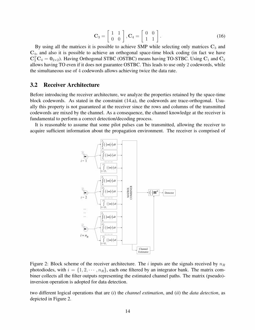
It is reasonable to assume that some pilot pulses can be transmitted, allowing the receiver toacquire sufficient information about the propagation environment. The receiver is comprised of
... ... ...
MA
TR
IX
CO
MB
INE
R
Channel
Estimator
Detector
i = 1
i = 2
...
...
...
⋅( )H#
⋅( )m t( )dt0
TP
∫
⋅( )m t( )dtTP
2TP
∫
i = nR
⋅( )m t( )dtL−1( )T
P
LTP
∫
... ... ...
⋅( )m t( )dt0
TP
∫
⋅( )m t( )dtTP
2TP
∫
⋅( )m t( )dtL−1( )T
P
LTP
∫
... ... ...
⋅( )m t( )dt0
TP
∫
⋅( )m t( )dtTP
2TP
∫
⋅( )m t( )dtL−1( )T
P
LTP
∫
Figure 2: Block scheme of the receiver architecture. The i inputs are the signals received by nR
photodiodes, with i = 1, 2, · · · , nR, each one filtered by an integrator bank. The matrix com-biner collects all the filter outputs representing the estimated channel paths. The matrix (pseudo)-inversion operation is adopted for data detection.
two different logical operations that are (i) the channel estimation, and (ii) the data detection, asdepicted in Figure 2.
14

Channel estimationThe channel estimation task requires special training sequences. By considering the channel rep-resentation in (6), it appears evident that for a matrix C equal to identity (i.e., when L = nT ), thereceived matrix Y equates (H+W), thus meaning that in the estimation procedure the only sourceof error is noise. This implicitly means that a number of L symbols (with L equals to nT ) is neededfor the estimation procedure.
Let us observe the receiver architecture depicted in Figure 2. At the i-th photodiode, the i-thsignal is filtered by an integrator bank, in order to compare it with m(t) that is the receiver mask(in this case, set equal to x(t), so as to implement the matched filter). Moreover, each integratoris time-shifted, so that it can capture the energy on different L-PPM symbols/intervals; this isoperated by each branch corresponding to each photodiode.
The matrix combiner collects all the filter outputs that represent the estimated channel paths.This simple estimation requires only nT · Ts seconds,6 under the simplifying assumption of a flat(frequency) channel, which is reasonable in very short range applications. Otherwise, mechanismssuch as presented in reference [59] can reduce the delay spread, confirming the importance ofchannel estimation. This kind of estimation can be also improved via the transmission of moreextensive pilot symbols (corresponding to Ne), so as to gather more energy. One important issueis related to how frequently pilot symbols are required to be sent in order to acquire channel infor-mation. The pilot rate, that is the rate used for sending pilots, depends on channel coherence time.We can argue that changes incur over a time horizon of seconds since the channel changes due to(i) movements performed by the receiver (user) or (ii) reflecting objects in the room. So settingpilot rate of the order of half a second should be sufficient to have sufficiently fresh estimates.
Data detectionIn the more general case of signal spread by the channel, the performance of the estimator isstrongly affected by synchronization. Under the quite satisfied assumption of minimum phasechannel [59], we are required to have synchronization and a sufficient guard time in order to avoidpulse overlap and also a good estimation of the main path. Minimum phase channels are character-ized to have main paths in the first samples. In order to avoid temporal ISI, it suffices to introduceguard times. However, if the channel is not minimum phase and presents long delays and maincomponents in the middle of channel impulse response, the guard times are not suitable, and othermechanisms (e.g., cyclic prefix), should be used.
As stated before, the presence of the channel mixes the spatial components, and even in theabsence of noise, the trace properties of the matrices are altered due to channel. This suggests tospatially solve the channel by inverting it via a matrix inversion operation (in the case of squaredmatrix), or via the use of a pseudo-inverse matrix (used for rectangular matrix), as shown in Fig-ure 2. From a computational point of view, this operation is inexpensive because it can be imple-mented through a shift register storing data and a simple algorithm (e.g., QR or Singular ValueDecomposition) to operate the pseudo-inversion before a matrix product.
After the optical-to-electrical conversion operated by the photodiode, the received matrix Yshould be processed in order to obtain a decision variable (i.e., Z) defined as follows
6This expression is due to the single receiver, which receives Y = H , in low noise condition. Thus, the channel isobtained by the output of each photodiode.
15
Z = YH] = X + WH], (17)
where the symbol ] means (i) inversion or (ii) pseudo-inversion operation, depending on the matrixdimension i.e., (i) squared or (ii) rectangular, respectively. This is a spatial Zero Forcing procedure(ZF).
Once obtained the decision variable Z, the decided codeword will be
C = arg maxi
TrCTi Z. (18)
This decision mechanism directly comes from reference 17. When the space-filtered noise WH]
in (17) is negligible, Z approaches X, and since the matrices are trace orthogonal we can recognizethe transmitted codeword. Finally, the detection mechanism is applied to Nd consecutive matrixcodewords. Notice that the following three steps: i) matrix inversion, ii) the product of the receivedmatrix by the pseudo-inverse, and iii) data detection are quite simple to implement and not costlyfrom a computational standpoint since L and nT , nR are limited to be in the range [2, 16] for L,and [1, 16] for nT and/or nR.
One important aspect is related to possible rank deficient property of the channel matrix. It isworthwhile noting that the channel estimation is affected by noise. So, even though the matrix rankis deficient (due to correlation among channels), the effect of noise affects the spatial correlationthat is lost. This means we have a performance loss due to imperfect channel estimation, even ifpseudoinversion can be still performed.
3.3 Performance evaluationStarting from the orthogonality exhibited in the trace sense, it is possible to evaluate the perfor-mance in terms of bit error probability that leads to solve possible ambiguities in determining thenT and M values needed for meeting constraints. The bit error probability Pre can be upper-bounded by the so called Union-Bound as follows7:
Pre ≤∫H
M∑i=1
M∑j=1,j 6=i
PrX = Cj|Ci,HPrH. (19)
The role played by the channel is conditioning. It is reasonable that different statistical modelingLOS, ND-LOS, and NLOS lead to different Pre. Moreover, the inequality holds for the condi-tioned probability, and since the average on channel statistics is performed at right and left side(with the same weight that is channel probability density function) this holds also the uncondi-tioned error probability. The upper bound for the term PrX = Cj|Ci,H can be evaluatedstarting from the detection criterion in (18), so the transmitted codeword Ci is –wrongly– decodedas Cj with the following pairwise upper bound on probability:
PrX = Cj|Ci,H ≤ PrTrCTj Z > TrCT
i Z, (20)
7We indicate with X the detected codeword according to (18). So, we implicitly state that X ≡ C even if, for sakeof readability, we prefer here, to use the symbolic representation of the detected codeword X related to the transmittedcodeword X.
16

that can be rewritten as:
PrX = Cj|Ci,H ≤PrTrCT
j Ci + CTj WH] > TrCT
i Ci + CTi WH], (21)
where we replaced Z = Ci + WH].Once noted that TrA+B = TrA+ TrB, TrCT
j Ci = 0, and TrCTi Ci = nT , we can
rewrite the probability in (21) as follows
PrX = Cj|Ci,H ≤PrTrCT
j WH] > nT + TrCTi WH]. (22)
This last can be evaluated by resorting to a multivariate Gaussian distribution. Even if the nature ofnoise is different (Gaussian and Poisson), under the hypothesis of several light sources / reflections,the central limit theorem allows assuming the white noise as Gaussian. Then, by considering thelinear combination induced among the noise samples by Cj , Ci, and H] –still providing a Gaussianrandom variable–, and also starting from a spatially white correlation for W, once vectorized itthrough the vec(.) operator, the new linearly combined noise variable n should be higher8 than nT ,i.e.
PrX = Cj|Ci,H ≤ Prn > nT. (23)
The Union Bound cannot be expressed in closed form since it depends on channel statistics.As anticipated, this implicitly suggests that the problem described in (14) should be tackled off-line during system planning and setup. Once the channel statistics are known (and this dependson several parameters and propagation scenarios), it is possible to determine the L, nT and nR
combination for meeting the constraints onR?, and Pre?. There is no algorithm to solve this butit should be simply computed for exhaustive search. This may appear costly, however since weare working with small numbers L = 2, 4, 8, 16, and the maximum rate is upper-bounded by SMP,giving indication of the feasibility of the system, we can conclude that this can be implementedwith MATLAB calculus tools in few seconds. Other approaches as binary programming can bepursued to speed up the solution searching. As a conclusive remark about computational costs, wecan argue that this is an off-line project tool for TO-SBTC, thus time saving is not an issue.
4 Numerical ResultsThe simulations have been developed under the parameter assumptions collected in Table 1 if notdifferently specified, both under the optimistic assumption of perfect channel knowledge at thereceiver, and imperfect channel state information (at the receiver) due to estimation errors. TheBER simulations are obtained via Monte-Carlo method. The channel model between each LEDand photodiode has been obtained through the CandLES simulator [61]. In the simulations we
8As an example, let us consider the code represented by matrices C3 and C4, then (23) becomes
PrX = C4|C3,H == Pr(w21 − w11)(h
]11 + h]
12)− (w22 − w12)(h]21 + h]
22) > nT .
17

assumed that the PPM time shift ∆ equates Ts = 12.98 · 10−9 s. Also, the numerical results areaveraged over the spatial area described by the assumptions reported in Table 1.
In the simulations, the SNR is referred both to optical and thermal noise in order to evaluate aworst case scenario. In particular, the overall noise is given by
N = 2q(Ip + Id)∆f + 4kpTF∆f/Rf , (24)
where Ip [A] is the average current, Id [A] the dark current, ∆f [Hz] the detector bandwidth, qelectron charge, kp [JK−1] Boltzmann constant, T [K] the temperature, F noise factor, and Rf [Ω]amplifier feedback resistance. From (24), it follows that
SNR =(RP
(opt)r )2
2q(Ip + Id)∆f + 4kpTF∆f/Rf
, (25)
that represents a worst case since optical and thermal noise components are simultaneously con-sidered. Here R is the photodiode responsivity and P (opt)
r is the received optical power.
5
10
150
24
68
107
108
109
nT
L
Rat
e [b
it/s
]
Spatial Multiplexing Rate
TO−STBC Rate
Figure 3: Achievable rates for different values of L and nT , when SM and STBC are considered.
Figure 4 depicts the BER obtained for different values of L, and nT , nR in a NLOS scenario.Notice how while passing from (L = nT = nR = 2) (with a rate of 38 Mbit/s) to (L = 4, nT =nR = 2) (same rate), the BER decreases with the same slope since only a coding gain, in SNRsense, is obtained. The gain offered by the (L = nT = nR = 4) configuration, with a rate of156 Mbit/s, quickly achieves 10−9 at an SNR less than 14 dB, even if this configuration requires 2more LEDs and 2 more photodiodes, w.r.t. the previous two configurations. The above gain can beobserved also in terms of diversity. In fact the slope of nT = 4, nR = 4 and L = 4 case is highersince we are increasing the dimension of the MIMO system so leading to higher diversity gain).All the above results are obtained in line with the problem in (14) by asking for matrices to be TO.
The tri-dimensional plot in Figure 3 shows the simultaneous effect on achievable rate of thenumber L of PPM symbols and of the number nT of LEDs, according to (9). The two surfacesare related to the SMP scenario, that is an upper bound for rate, and the transmission rate obtainedby using TO-STBC. ¿From a feasibility point of view, the TO-STBC rate indicates the maximum
18

0 5 10 15 2010
−10
10−8
10−6
10−4
10−2
100
SNR [dB]
BE
R
L=2, nT=2, n
R=2, Rate=38 Mb/s
L=4, nT=2, n
R=2, Rate=38Mb/s
L=4, nT=4, n
R=4, Rate=156Mb/s
Figure 4: BER vs. SNR for MIMO-PPM with different values of L, nT and nR in NLOS scenario.
achievable transmission rate under the constraint on the codewords to maintain the TO property.This implicitly means that a rate over-bounding the STBC rate, for an assigned value of L and nT ,cannot retain the TO properties so its BER is higher with respect to the one obtained with TO.
By increasing L from 2 to 16, the value of R related to SMP decreases from 38.5 Mbit/s to19 Mbit/s, when only 1 LED-photodiode pair is considered, while for 8 LED-photodiode pairs,the achievable rate falls from 308 Mbit/s to 154.5 Mbit/s (with blue filter). This suggests thatincreasing the order of L-PPM modulation is not worth, while increasing the number of LEDs /photodiodes allows achieving very high rates. The limitation given by the L-PPM order may befixed by adapting the Ts value to make the product (L · Ts) in (9) constant. In order to do so, atechnological issue should be tackled since, as previously anticipated, this is strictly tied to theability of LEDs to quickly perform the electrical-to-optical conversion. Regarding the STBC rate,its behavior with one LED is the same of SMP, while for L = 16 the maximum rate is around150 Mbit/s.
Furthermore, due to the important role of channel knowledge, we evaluated the channel robust-ness, as compared to an imperfect channel knowledge for statistically modeled channels. Evenif the channel is slowly time-variant, when the relative positions between LEDs and photodiodeschange, and new reflections are present, the propagation scenario is different. So, a sporadic pilotsignaling is needed via pilots for channel knowledge acquisition. Under the hypothesis of havinga data link layer able to operate error detection, the new estimation may be performed once anerror has been detected. Alternatively, this can also be operated in real devices via accelerometersensors, able to detect receiver movements.
In Fig. 5, increasing values of σ2h refers to a imperfect channel state information detection; in
practical scenarios, this may be due to users moving in the room (i.e., interferers), photodiodemoved or external light sources added to the LED signal at the photodiode (i.e., ambient noise).
The channel model is obtained through the use of CandLES simulator, and the comparison withMaximum Likelihood (ML) and Minimum Mean Square Error (MMSE) has been reported. We
19
4 6 8 10 12 14 16 18 20 22 2410
−8
10−7
10−6
10−5
10−4
10−3
10−2
10−1
100
SNR [dB]
BE
R
ML σh
2 = 0
MMSE σh
2 = 0
ZF σh
2 = 0
ML σh
2 = 0.2
MMSE σh
2 = 0.2
ZF σh
2 = 0.2
ML σh
2 = 0.4
MMSE σh
2 = 0.4
ZF σh
2 = 0.4
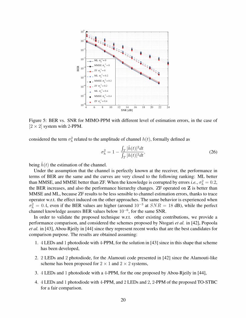
Figure 5: BER vs. SNR for MIMO-PPM with different level of estimation errors, in the case of[2× 2] system with 2-PPM.
considered the term σ2h related to the amplitude of channel h(t), formally defined as
σ2h = 1−
∫T|h(t)|2dt∫
T|h(t)|2dt
, (26)
being h(t) the estimation of the channel.Under the assumption that the channel is perfectly known at the receiver, the performance in
terms of BER are the same and the curves are very closed to the following ranking: ML betterthan MMSE, and MMSE better than ZF. When the knowledge is corrupted by errors i.e., σ2
h = 0.2,the BER increases, and also the performance hierarchy changes. ZF operated on Z is better thanMMSE and ML, because ZF results to be less sensible to channel estimation errors, thanks to traceoperator w.r.t. the effect induced on the other approaches. The same behavior is experienced whenσ2h = 0.4, even if the BER values are higher (around 10−3 at SNR = 18 dB), while the perfect
channel knowledge assures BER values below 10−6, for the same SNR.In order to validate the proposed technique w.r.t. other existing contributions, we provide a
performance comparison, and considered the schemes proposed by Ntogari et al. in [42], Popoolaet al. in [43], Abou-Rjeily in [44] since they represent recent works that are the best candidates forcomparison purpose. The results are obtained assuming:
1. 4 LEDs and 1 photodiode with 4-PPM, for the solution in [43] since in this shape that schemehas been developed,
2. 2 LEDs and 2 photodiode, for the Alamouti code presented in [42] since the Alamouti-likescheme has been proposed for 2× 1 and 2× 2 systems,
3. 4 LEDs and 1 photodiode with a 4-PPM, for the one proposed by Abou-Rjeily in [44],
4. 4 LEDs and 1 photodiode with 4-PPM, and 2 LEDs and 2, 2-PPM of the proposed TO-STBCfor a fair comparison.
20
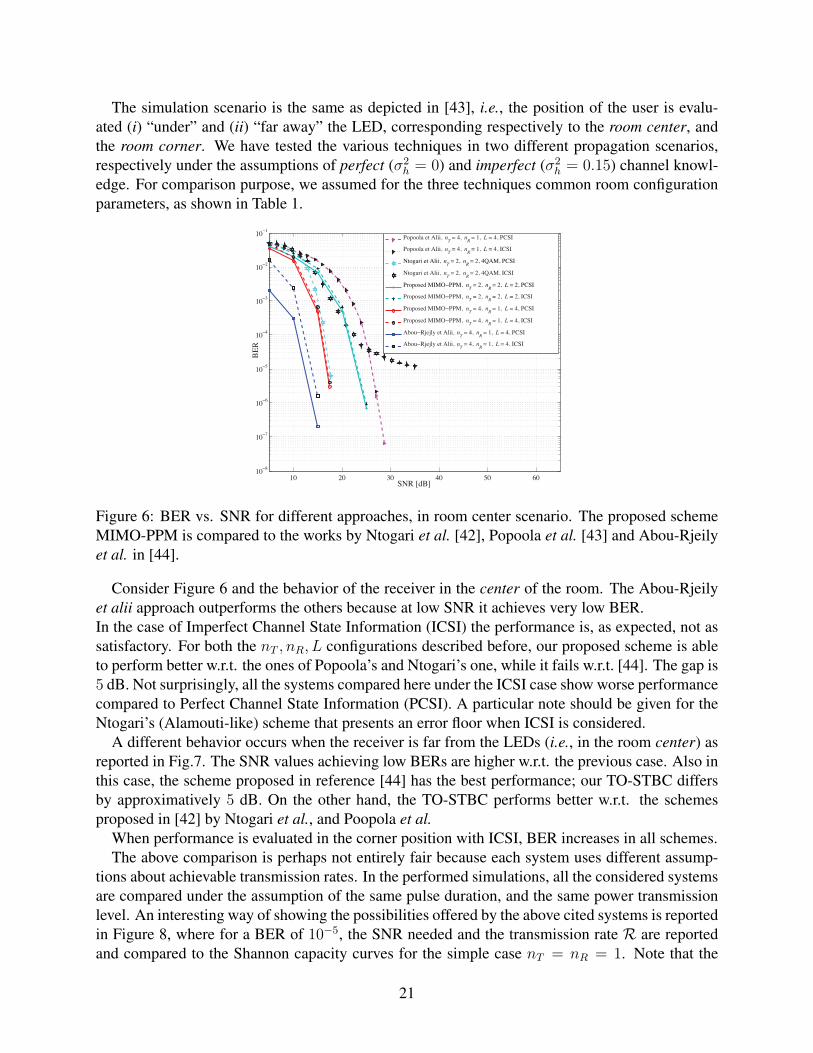
The simulation scenario is the same as depicted in [43], i.e., the position of the user is evalu-ated (i) “under” and (ii) “far away” the LED, corresponding respectively to the room center, andthe room corner. We have tested the various techniques in two different propagation scenarios,respectively under the assumptions of perfect (σ2
h = 0) and imperfect (σ2h = 0.15) channel knowl-
edge. For comparison purpose, we assumed for the three techniques common room configurationparameters, as shown in Table 1.
10 20 30 40 50 6010
−8
10−7
10−6
10−5
10−4
10−3
10−2
10−1
SNR [dB]
BE
R
Popoola et Alii, n
T = 4, n
R = 1, L = 4, PCSI
Popoola et Alii, nT = 4, n
R = 1, L = 4, ICSI
Ntogari et Alii, nT = 2, n
R = 2, 4QAM, PCSI
Ntogari et Alii, nT = 2, n
R = 2, 4QAM, ICSI
Proposed MIMO−PPM, nT = 2, n
R = 2, L = 2, PCSI
Proposed MIMO−PPM, nT = 2, n
R = 2, L = 2, ICSI
Proposed MIMO−PPM, nT = 4, n
R = 1, L = 4, PCSI
Proposed MIMO−PPM, nT = 4, n
R = 1, L = 4, ICSI
Abou−Rjejly et Alii, nT = 4, n
R = 1, L = 4, PCSI
Abou−Rjejly et Alii, nT = 4, n
R = 1, L = 4, ICSI
Figure 6: BER vs. SNR for different approaches, in room center scenario. The proposed schemeMIMO-PPM is compared to the works by Ntogari et al. [42], Popoola et al. [43] and Abou-Rjeilyet al. in [44].
Consider Figure 6 and the behavior of the receiver in the center of the room. The Abou-Rjeilyet alii approach outperforms the others because at low SNR it achieves very low BER.In the case of Imperfect Channel State Information (ICSI) the performance is, as expected, not assatisfactory. For both the nT , nR, L configurations described before, our proposed scheme is ableto perform better w.r.t. the ones of Popoola’s and Ntogari’s one, while it fails w.r.t. [44]. The gap is5 dB. Not surprisingly, all the systems compared here under the ICSI case show worse performancecompared to Perfect Channel State Information (PCSI). A particular note should be given for theNtogari’s (Alamouti-like) scheme that presents an error floor when ICSI is considered.
A different behavior occurs when the receiver is far from the LEDs (i.e., in the room center) asreported in Fig.7. The SNR values achieving low BERs are higher w.r.t. the previous case. Also inthis case, the scheme proposed in reference [44] has the best performance; our TO-STBC differsby approximatively 5 dB. On the other hand, the TO-STBC performs better w.r.t. the schemesproposed in [42] by Ntogari et al., and Poopola et al.
When performance is evaluated in the corner position with ICSI, BER increases in all schemes.The above comparison is perhaps not entirely fair because each system uses different assump-
tions about achievable transmission rates. In the performed simulations, all the considered systemsare compared under the assumption of the same pulse duration, and the same power transmissionlevel. An interesting way of showing the possibilities offered by the above cited systems is reportedin Figure 8, where for a BER of 10−5, the SNR needed and the transmission rate R are reportedand compared to the Shannon capacity curves for the simple case nT = nR = 1. Note that the
21

5 10 15 20 25 30 3510
−11
10−10
10−9
10−8
10−7
10−6
10−5
10−4
10−3
10−2
10−1
SNR [dB]
BE
R
Popoola et Alii, nT = 4, n
R = 1, L = 4, PCSI
Popoola et Alii, nT = 4, n
R = 1, L = 4, ICSI
Ntogari et Alii, nT = 2, n
R = 2, 4 QAM, PCSI
Ntogari et Alii, nT = 2, n
R = 2, 4 QAM, ICSI
Proposed MIMO−PPM, nT = 2, n
R = 2, L = 2, PCSI
Proposed MIMO−PPM, nT = 2, n
R = 2, L = 2, ICSI
Proposed MIMO−PPM, nT = 4, n
R = 1, L = 4, PCSI
Proposed MIMO−PPM, nT = 4, n
R = 1, L = 4, ICSI
Abou−Rjejly et Alii, nT = 4, n
R = 1, L = 4, PCSI
Abou−Rjejly et Alii, nT = 4, n
R = 1, L = 4, ICSI
Figure 7: BER vs. SNR for different approaches, in room corner scenario. The proposed schemeMIMO-PPM is compared to the works by Ntogari et al. [42], Popoola et al. [43] and Abou-Rjeilyet al. in [44].
Shannon curve does not consider the features typical of the optical link (no negative signals andGaussian and Poisson disturbance), so in this sense it is a bit optimistic since, due to a bias opticalsignal, the power to be spent must be higher so it is an upper bound.
Safari et al. [49] is able to achieve the target BER with a very low SNR; however, at the expenseof reducing transmission rate of the PAM-based modulation due to the repetition coding used (Nin the plot indicates the number of repetitions of the same symbol). On the other hand, the targetBER the scheme proposed by Poopola et al. [43] achieves a very good transmission rate (i.e.,77 Mbit/s), at the expense of transmission power. This is not a heavy drawback if we resort to adownlink scheme, although it strongly increases the negative effect if an uplink is considered. Amodestly higher performance, expressed in terms of rate, is achieved by Ntogari et al. [42] underthe assumption of 4-QAM even if it requires perfect channel knowledge and high transmissionpower. They achieve 150 Mbit/s. The MIMO-OOK (independent OOK transmission of 4 differentLEDs as SM) performs well in terms of rate (300 Mbit/s), while fails on power efficiency. SISO-OOK is under MIMO-OOK in terms of rate even if it requires less power to achieve the targetBER. SISO 4-PPM is a bit worse w.r.t. SISO OOK due to the spectral inefficiency of PPM whileit gains in terms of SNR.
Regarding the contribution in reference [44] that exhibits the best considered BER, it clearly is inthe left part of the plot because low SNR is required for the target BER. Since that scheme presentsmatrices of dimensions LnT × nT , this reduces its rate because LnTTs are needed to transmit acodeword. Finally, the proposed TO-STBC performs well for the nT = 4, nR = 1, 4-PPM becauseit is at the same level of MIMO-OOK with a considerable gain in terms of power. It has half ofthe rate of Ntogari’s approach but with less power, more robustness w.r.t. channel knowledge, andhas simplicity of realization. The nT = 2, nR = 2, 2-PPM scheme is in-between w.r.t. nT = 4,nR = 1, 4-PPM performances of the proposed scheme, and the one of reference [48].
22

0 5 10 15 20 25 30 35 4010
7
108
109
1010
SNR [dB]
Rat
e [b
it/s
]
nT = 1, n
R = 1 Channel capacity
Safari et Alii
SISO 4−PPM
SISO OOK
Poopola et Alii, nT = 4, n
R = 1, 4−PPM
Ntogari et Alii, nT = 2, n
R = 2, 4−QAM
Abou−Rjeily et Alii, nT = 4, n
R = 1, 4−PPM
MIMO−OOK, SM, nT = 4, n
R = 1
Proposed MIMO−PPM, nT = 4, n
R = 1, 4−PPM
Proposed MIMO−PPM, nT = 2, n
R = 2, 4−PPM
N = 6 N = 5
N = 2
N = 3 N = 4
Figure 8: Rate vs. SNR at BER 10−5 for different schemes with respect to traditional SISO channelShannon capacity.
5 ConclusionsIn this paper we have presented a MIMO-PPM scheme based on STBC under the constraint ofmatrices to be trace orthogonal (TO-STBC). The proposed technique aims to enhance performancein indoor VLC system. The TO-STBC architecture aims at finding the so called via media betweena low BER and a high data rate without requiring complex hardware implementation. Even if PPMis known to be bandwidth inefficient, through the use of multiple LEDs and photodetectors it ispossible to gain in rate and BER, and counterbalance any PPM inefficiencies.
The performance offered by this system is comparable with contemporary schemes proposed inthe literature. In detail, the proposed scheme does not present the lowest BER or the highest ratebut it stresses the transmission rate–error-rate trade-off. Specifically, we argue that the compro-mise between these performance metrics is superior to what exists in the current literature. Verylow BER-achieving systems lose more than the proposed approach in terms of rate, while bettersystems in terms of rate are required to use more transmission power to achieve similar perfor-mance.
References[1] D. C. O’Brien et al., “Indoor Visible Light Communications: challenges and prospects,” Proc
of SPIE, vol. 7091, 2008.
[2] M. Kavehrad, “Sustainable energy-efficient wireless applications using light,” IEEE Commu-nications Magazine, December 2010.
[3] T. Borogovac, M. Rahaim, and J. B. Carruhers, “Spotlighting for visible light communica-tions and illumination,” in Workshop on Optical Communications, GLOBECOM, 2010.
23

[4] F. Szczot, “Safety problems in free space optical transmission,” Proceedings of SPIE, vol.6159, 2006.
[5] J. Vucic et al., “513 Mbit/s Visible Light Communications Link Based on DMT-Modulationof a White LED,” Journal of Lightwave Technology, vol. 28, no. 24, 2010.
[6] J. Vucic, C. Kottke, K. Habel, and K.-D. Langer, “803 Mbit/s Visible Light WDM Linkbased on DMT Modulation of a Single RGB LED Luminary,” in Optical Fiber Communi-cation Conference and Exposition (OFC/NFOEC) and the National Fiber Optic EngineersConference, March 2011.
[7] J. Armstrong and B. Schmidt, “Comparison of asymmetrically clipped optical ofdm and dc-biased optical ofdm in awgn,” Communications Letters, IEEE, vol. 12, no. 5, pp. 343–345,2008.
[8] L. Chen, B. Krongold, and J. Evans, “Performance analysis for optical ofdm transmission inshort-range im/dd systems,” Lightwave Technology, Journal of, vol. 30, no. 7, pp. 974–983,2012.
[9] Y. F. Liu, C. H. Yeh, C. W. Chow, Y. Liu, Y. L. Liu, and H. K. Tsang, “Demonstration ofbi-directional led visible light communication using tdd traffic with mitigation of reflectioninterference,” Opt. Express, vol. 20, no. 21, pp. 23 019–23 024, Oct 2012. [Online].Available: http://www.opticsexpress.org/abstract.cfm?URI=oe-20-21-23019
[10] J. Dang and Z. Zhang, “Comparison of optical ofdm-idma and optical ofdma for uplink vis-ible light communications,” in Wireless Communications Signal Processing (WCSP), 2012International Conference on, 2012, pp. 1–6.
[11] M. Biagi, A. Vegni, and T. Little, “LAT Indoor MIMO-VLC –Localize, Access and Transmit–,” in Proc. of Intl. Workshop on Optical Wireless Communications, Pisa, Italy, October 222012.
[12] O.-S. and Health-Branch-Labour-Department, Simple Guide to Health Risk Assessment - Of-fice Environment Series OE 2/99, 1998.
[13] J. Grubor, S. Randel, K. Langer, and J. W. Walewski, “Broadband Information BroadcastingUsing LED-Based Interior Lighting,” Journal of Lightwave Technology, vol. 26, pp. 3883–3892, 2008.
[14] S. Hranilovic and F. Kschischang, “A Pixelated MIMO Wireless Optical CommunicationSystem,” IEEE Journal of Selected Topics in Quantum Electronics, vol. 12, pp. 859–874,July/August 2006.
[15] D. Gesbert, M. Shafi, D. shan Shiu, P. Smith, and A. Naguib, “From Theory to Practice: AnOverview of MIMO Space-Time Coded Wireless Systems,” IEEE J. Sel. Areas Commun.,vol. 21, pp. 281–302, April 2003.
24

[16] P. Butala, H. Elgala, and T. Little, “SVD-VLC: a novel capacity maximizing VLC MIMOsystem architecture under illumination constraints,” in IEEE Globecom Workshops , Decem-ber 2013, pp. 1087–1092.
[17] ——, “Sample Indexed Spatial Orthogonal Frequency Division Multiplexing ,” Chinese Op-tics Letters (to appear) , vol. 12, 2014.
[18] S. M. Hass, S. J. H., and V. Tarokh, “Space-time codes for wireless optical communications,”EURASIP Journal of Applied Signal Processing, vol. 3, pp. 211–220, 2002.
[19] P. Haigh, Z. Ghassemlooy, F. Bausi, I. Papakonstantinou, H. Le Minh, S. Tedde, O. Hayden,and F. Cacialli, “Organic visible light communications: Recent progress,” in TransparentOptical Networks (ICTON), 2014 16th International Conference on, July 2014, pp. 1–5.
[20] P. Haigh, Z. Ghassemlooy, I. Papakonstantinou, F. Tedde, S. Tedde, O. Hayden, and S. Ra-jbhandari, “A mimo-ann system for increasing data rates in organic visible light communi-cations systems,” in Communications (ICC), 2013 IEEE International Conference on, June2013, pp. 5322–5327.
[21] P. Haigh, Z. Ghassemlooy, H. L. Minh, S. Rajbhandari, F. Arca, S. Tedde, O. Hayden, andI. Papakonstantinou, “Exploiting equalization techniques for improving data rates in organicoptoelectronic devices for visible light communications,” Lightwave Technology, Journal of,vol. 30, no. 19, pp. 3081–3088, Oct 2012.
[22] S. Jivkova, B. Hristov, and M. Kavehrad, “Power-efficient Multispot-diffuse Multiple-input-multiple-output Approach to broad-band Optical Wireless Communications,” IEEE Trans.Veh. Technol., vol. 53, no. 3, pp. 882–889, May 2004.
[23] L. Zeng, D. O’Brien, H. Minh, G. Faulkner, K. Lee, D. Jung, Y. Oh, and E. T. Won, “High datarate Multiple Input Multple Output (MIMO) Optical Wireless Communications using WhiteLED Lighting,” IEEE J. Sel. Areas Commun., vol. 27, no. 9, pp. 1654–1662, December 2009.
[24] R. M. R. Mesleh, H. Helgala and H.Haas, “Performance of optical spatial modulation withtransmitters-receivers alignment,” IEEE Communication Letters, vol. 15, no. 1, pp. 79–81,2011.
[25] T. Fath and H. Haas, “Performance Comparison of MIMO Techniques for Optical WirelessCommunications in Indoor Environments,” IEEE Transactions on Communications, vol. 61,pp. 733–742, February 2013.
[26] ——, “Optical Spatial Modulation using Colour LEDs,” in IEEE ICC 2013 - Optical Net-works and Systems, June 2013, pp. 3938–3942.
[27] M. Di Renzo, H. Haas, A. Ghrayeb, S. Sugiura, and L. Hanzo, “Spatial modulation for gener-alized mimo: Challenges, opportunities, and implementation,” Proceedings of the IEEE, vol.102, no. 1, pp. 56–103, Jan 2014.
[28] J. Esch, “Prolog to ”spatial modulation for generalized mimo: Challenges, opportunities, andimplementation”,” Proceedings of the IEEE, vol. 102, no. 1, pp. 53–55, Jan 2014.
25

[29] G. Yun and M. Kavehrad, “Spot-diffusing and Fly-Eye Receivers for Indoor Infrared WirelessCommunications,” in Proc. of IEEE Int. Conf. Selected Topics in Wireless Communications,1992, pp. 262–265.
[30] S. Wilson, M. Brandt-Pearce, Q. Cao, and J. Leveque, “Optical MIMO transmission usingQ-ary PPM for atmospheric channels,” in Proc. 37th Asilomar Conf. Signals, Systems andComputers, vol. 19, Pacific Grove, CA, November 12 2003, p. 2361.
[31] M. Garfield, C. Liang, T. Kurzweg, and K. R. Dandekar, “MIMO space-time Coding forDiffuse Optical Communication,” Microw. Opt. Technol. Lett., vol. 48, pp. 1108–1110, June2006.
[32] S. Hranilovic and F. R. Kschischang, “Short-range Wireless Optical Communication usingPixilated Transmitters and Imaging Receivers,” in Proc. 2004 IEEE Int. Conf. Communica-tions, Paris, France, June 20–24 2004.
[33] R. Mesleh, R. Mehmood, H. Elgala, and H. Haas, “Indoor MIMO Optical Wireless Commu-nication using Spatial Modulation,” in Proc. IEEE Int. Conf. Communications (ICC), CapeTown, South Africa, May 23–27 2010, pp. 1–5.
[34] P. Butala, H. Elgala, and T. Little, “Performance of Optical Spatial Modulation and SpatialMultiplexing with Imaging Receiver,” in IEEE WCNC’14, Istanbul, Turkey, April 2014.
[35] D. O’Brien, “Multi-input multi-output (MIMO) Indoor Optical Wireless Communications,”in Proc. of Signals, Systems and Computers, Conference Record of the Forty-Third Asilomar,November 1-4, 2009, pp. 1636–1639.
[36] K.-H. Park, Y.-C. Ko, and M.-S. Alouini, “On the Power and Offset Allocation for RateAdaptation of Spatial Multiplexing in Optical Wireless MIMO Channels,” in Proc. of 7thIntl. Wireless Communications and Mobile Computing Conference, July 4-8 2011, pp. 141–146.
[37] A. Burton, H. L. Minh, Z. Ghassemlooy, E. Bentley, and C. Botella, “Experimental demon-stration of 50-mb/s visible light communications using 4 , times, 4 mimo,” Photonics Tech-nology Letters, IEEE, vol. 26, no. 9, pp. 945–948, May 2014.
[38] F.-M. Wu, C.-T. Lin, C.-C. Wei, C.-W. Chen, H.-T. Huang, and C.-H. Ho, “1.1-gb/s white-led-based visible light communication employing carrier-less amplitude and phase modulation,”Photonics Technology Letters, IEEE, vol. 24, no. 19, pp. 1730–1732, Oct 2012.
[39] A. Khalid, G. Cossu, R. Corsini, P. Choudhury, and E. Ciaramella, “1-gb/s transmission overa phosphorescent white led by using rate-adaptive discrete multitone modulation,” PhotonicsJournal, IEEE, vol. 4, no. 5, pp. 1465–1473, Oct 2012.
[40] J.-h. Choi, E.-b. Cho, Z. Ghassemlooy, S. Kim, and C. Lee, “Visible lightcommunications employing ppm and pwm formats for simultaneous data transmissionand dimming,” Optical and Quantum Electronics, pp. 1–14, 2014. [Online]. Available:http://dx.doi.org/10.1007/s11082-014-9932-0
26
[41] D. Tsonev, S. Sinanovic, and H. Haas, “Practical mimo capacity for indoor optical wirelesscommunication with white leds,” in Vehicular Technology Conference (VTC Spring), 2013IEEE 77th, June 2013, pp. 1–5.
[42] G. Ntogari, T. Kamalakis, and T. Sphicopoulos, “Performance analysis of space time blockcoding techniques for indoor optical wireless systems,” Selected Areas in Communications,IEEE Journal on, vol. 27, no. 9, pp. 1545 –1552, december 2009.
[43] W. Popoola, E. Poves, and H. Haas, “Spatial pulse position modulation for optical communi-cations,” Lightwave Technology, Journal of, vol. 30, no. 18, pp. 2948 –2954, sept.15, 2012.
[44] C. Abou-Rjeily and W. Fawaz, “Space-time codes for mimo ultra-wideband communicationsand mimo free-space optical communications with ppm,” Selected Areas in Communications,IEEE Journal on, vol. 26, no. 6, pp. 938–947, 2008.
[45] C. Abou-Rjeily and M. Bkassiny, “Unipolar space-time codes with reduced decoding com-plexity for th-uwb with ppm,” Wireless Communications, IEEE Transactions on, vol. 8,no. 10, pp. 5086–5095, 2009.
[46] C. Abou-Rjeily, “Orthogonal space-time block codes for binary pulse position modulation,”Communications, IEEE Transactions on, vol. 57, no. 3, pp. 602–605, 2009.
[47] C. Abou-Rjeily and Z. Baba, “Achieving full transmit diversity for ppm constellations withany number of antennas via double position and symbol permutations,” Communications,IEEE Transactions on, vol. 57, no. 11, pp. 3235–3238, 2009.
[48] V. Tarokh, N. Seshadri, and A. R. Calderbank, “Space-time codes for high datarate wireless communication: performance criterion and code construction,” IEEETrans. Inf. Theor., vol. 44, no. 2, pp. 744–765, Sep. 2006. [Online]. Available:http://dx.doi.org/10.1109/18.661517
[49] M. Safari and M. Uysal, “Do we really need ostbcs for free-space optical communicationwith direct detection?” Wireless Communications, IEEE Transactions on, vol. 7, no. 11, pp.4445–4448, 2008.
[50] X. Song and J. Cheng, “Subcarrier intensity modulated mimo optical communications inatmospheric turbulence,” Optical Communications and Networking, IEEE/OSA Journal of,vol. 5, no. 9, pp. 1001–1009, Sept 2013.
[51] E. Bayaki and R. Schober, “On space-time coding for free-space optical systems,”Trans. Comm., vol. 58, no. 1, pp. 58–62, Jan. 2010. [Online]. Available: http://dx.doi.org/10.1109/TCOMM.2010.01.080142
[52] H. Haas, “Wireless data from every light bulb,” in TED - Ideas worth Spreading, 2011, p.available at http : //www.ted.com/.
[53] S. Barbarossa, “Trace-orthogonal design of mimo systems with simple scalar detectors, fulldiversity and (almost) full rate,” in Signal Processing Advances in Wireless Communications,2004 IEEE 5th Workshop on, 2004, pp. 308–312.
27

[54] J. M. Kahn and J. R. Barry, “Wireless infrared communications,” Proceedings of the IEEE,vol. 85, no. 2, pp. 265–298, 1997.
[55] H. M. H. Shalaby, “Effect of thermal noise and apd noise on the performance of oppm-cdmareceivers,” Lightwave Technology, Journal of, vol. 18, no. 7, pp. 905–914, 2000.
[56] J. R. Barry, Wireless Infrared Communications. Kluwer, 1994.
[57] R. Ramirez-Iniguez, S. M. Idrus, and Z. Sun, Optical Wireless Communications. CRC Press,2008.
[58] J. M. Kahn and J. R. Barry, “Wireless infrared communications,” Proceedings of the IEEE,vol. 85, no. 2, pp. 265–298, February 1997.
[59] H. L. Minh et al., “100-Mb/s NRZ Visible Light Communications Using a PostequalizedWhite LED,” IEEE Photonics Technology Letters, vol. 21, no. 15, pp. 1063–1065, 2009.
[60] M. Biagi, T. Borogovac, and T. Little, “Adaptive receiver for indoor visible light communi-cations,” Lightwave Technology, Journal of, vol. 31, no. 23, pp. 3676–3686, Dec 2013.
[61] T. B. M. Rahaim and J. B. Carruthers, “Candles: Communications and lighting emulationsoftware,” in Fifth ACM International Workshop on Wireless Network Testbeds, ExperimentalEvaluation and Characterization, 2010.
[62] A.M.Vegni and M.Biagi, “An Indoor Localization Algorithm in a Small-Cell LED-basedLighting System,” in Proc. of IEEE Intern. Conf. on Indoor Positioning and Indoor Naviga-tion, 2012.
[63] A. K. Jain, Fundamentals of Digital Image Processing. Prentice Hall, 1989.
28