trace-driven co-simulation of high-performance … · trace-driven co-simulation of...
TRANSCRIPT
Trace-driven Co-simulation of High-PerformanceComputing Systems using OMNeT++
Cyriel MinkenbergIBM Zurich Research Laboratory
Säumerstrasse 48803 Rüschlikon, Switzerland
Germán Rodriguez HerreraIBM Zurich Research Laboratory
Säumerstrasse 48803 Rüschlikon, Switzerland
ABSTRACTIn the context of developing next-generation high-perfor-mance computing systems, there is often a need for an “end-to-end” simulation tool that can simulate the behaviour ofa full application on a reasonably faithful model of the ac-tual system. Considering the ever-increasing levels of paral-lelism, we take a communication-centric view of the systembased on collecting application traces at the message-passinginterface level. We present an integrated toolchain that en-ables the evaluation of the impact of all interconnection net-work aspects on the performance of parallel applications.The network simulator, based on OMNeT++, provides asocket-based co-simulation interface to the MPI task simu-lator, which replays traces obtained using an instrumenta-tion package. Both simulators generate output that can beevaluated with a visualization tool. A set of additional toolsis provided to translate generic topology files to OMNeT’sned format, import route files at run time, perform rout-ing optimizations, and generate particular topologies. Wealso present several examples of results obtained that pro-vide insights that would not have been possible without thisintegrated environment.
KeywordsHigh-performance computing, interconnection network, PDES.
1. INTRODUCTIONThe design of high-performance computing (HPC) sys-
tems relies to a large extent on simulations to optimize thevarious components of such a complex system. To evaluateprocessor performance, tools such as MAMBO [1] or SIMICS[2] are used, which can perform cycle-accurate simulationsof entire applications at the instruction level. However, sucha level of detail prevents scaling of this type of simulationto systems with more than a handful of processors.
The interconnection network of a HPC system is usu-ally modelled at a higher level of abstraction, resorting to
Permission to make digital or hard copies of all or part of this work forpersonal or classroom use is granted without fee provided that copies arenot made or distributed for profit or commercial advantage and that copiesbear this notice and the full citation on the first page. To copy otherwise, torepublish, to post on servers or to redistribute to lists, requires prior specificpermission and/or a fee.OMNeT++ 2009, Rome, Italy.Copyright 2009 ICST, ISBN 978-963-9799-45-5.
discrete-event simulation to enable scaling to systems withhundreds or thousands of network ports. The purpose of in-terconnection network simulation is to optimize the networktopology, switch and adapter architectures and parameters,scheduling and routing policies, link-level flow control mech-anism, and end-to-end congestion control mechanism. Thistype of simulation is commonly of the“Monte Carlo”variety,i.e., applying a synthetically generated workload with ran-dom destination and interarrival-time distributions, ratherthan the load from a real application.
Although such simulations are useful in determining load–throughput and load–delay characteristics, they are not nec-essarily a reliable performance indicator for the communi-cation phases of specific applications. Therefore, we havethe situation that instruction-level processor simulation, al-though accurate, does not scale to the desired system sizes,whereas interconnect simulation does scale, but suffers fromunrealistic stimuli. This gap needs to be bridged to enabletrue end-to-end full-system simulation.
One class of approaches to bridge this gap employs trace-driven simulation. Instead of by an exact model of theirbehavior, computing nodes are represented by a trace thatcontains two basic kinds of records, namely computation andcommunication. Computations are not actually performed,but simply represented by the amount of CPU time theywould consume in reality. Communications are transformedinto data messages that are fed to a model of the intercon-nection network. To ensure accurate results, the simula-tion should preserve causal dependencies between records,e.g., when a particular computation depends on data to bedelivered by a preceding communication, the start of thecomputation must wait for the communication to complete.As many scientific HPC applications are based on the Mes-sage Passing Interface (MPI), tracing MPI calls is a suitablemethod to characterize the communication patterns of animportant class of HPC workloads. An example of this ap-proach is the MARS simulator presented in [3].
The simulation framework described here is the result ofjoint project between the Barcelona Supercomputer Cen-ter (BSC) and IBM, in which a follow-on machine to thecurrently installed MareNostrum system is being designedunder the working title of MareIncognito. MareNostrum isa 2,560-node cluster of IBM JS21 blades, each having twodual-core IBM 64-bit PowerPCr 970MP processors runningat 2.3 GHz for a total of 10,240 CPUs. The computingnodes are interconnected by means of a high-bandwidth,low-latency Myrinetr network [5], with each blade havingone integrated Myrinet adapter. The switch fabric com-
prises ten 512-port and two 1280-port Myrinet switches ar-ranged in a two-level fat-tree topology. However, as theseswitches are constructed internally using 32-port switch el-ements (again arranged in a fat-tree topology), the networkreally has five levels. The nodes are also connected to aGigabit Ethernet local area network. MareNostrum has 20TB of RAM and 280 TB of external disk storage. Peakperformance with respect to the LINPACK benchmark is94.21 teraflops, which ranked it as the world’s 26th fastestsupercomputer on the Top500 list of June 2008.
Several teams at IBM and BSC are cooperating on key as-pects of the design of MareIncognito, including applications,programming models, tools, load balancing, interconnectionnetwork, processor, and system modeling. This paper de-scribes part of the effort responsible for the design of theinterconnection network.
The remainder of this paper is organized as follows. InSec. 3 we describe the existing BSC tools Dimemas and Par-aver and the IBM interconnection network simulator MARS.Section 4 explains how we integrated these tools to form aco-simulation platform for MPI applications using realisticinterconnection network models. Section 5 provides exam-ples of the type of new insights that this new environmentcan help generate. Finally, we conclude in Sec. 6.
2. INTERCONNECTION NETWORKThe role of the interconnection network in scientific as
well as commercial computer systems is of increasing im-portance. The underlying trend is that the growing demandfor computing capacity will be met through parallelism atthe instruction, thread, core, and machine levels.
The scale, speed, and efficiency of interconnects must growsignificantly, because of (i) increasing parallelism, (ii) the re-placement of computer busses by switched networks, (iii)consolidation of heterogeneous communication infrastruc-ture (storage area, local area, and clustering networks; IOand memory busses) onto a single physical network, and (iv)virtualization of computing resources that leads to increasedvariability and unpredictability in the network load.
As neither busses nor legacy LAN/WANs can meet alldatacenter and HPC requirements—notably low latency, highbandwidth, high reliability, and low cost—a number of net-working technologies designed specifically for the datacenterenvironment have emerged. Examples are Fibre Channel,commonly employed in storage area networks, Myrinet [5]and QsNet (Quadricsr), used for low-latency, high-bandwidthinter-process communication in HPC or clustering environ-ments, and InfiniBand, designed as a comprehensive data-center interconnect.
A consequence of these trends is that the interconnectionnetwork is becoming a more significant factor in both theoverall system performance and the overall system cost. Ac-cordingly, it is receiving more attention in the modelling ofsuch systems to determine the optimum cost-performancetrade-off. This is not possible without a detailed, faithfulrepresentation of all aspects pertaining to the network.
3. TOOLSTo perform a detailed performance analysis of parallel pro-
grams, BSC developed a simulation tool, Dimemas, and avisualization tool, Paraver. To study the performance of in-terconnection networks, IBM developed a tool referred to as
the MPI Application Replay network Simulator (MARS) [3].As these tools form the basis of our work, we briefly describethem below.
3.1 DimemasDimemas is a tool developed at BSC to analyze the perfor-
mance of message-passing programs. It is an event-drivensimulator that reconstructs the time behavior of message-passing applications on a machine modelled by a set of per-formance parameters.
The input to Dimemas is a trace containing a sequence ofoperations for each thread of each task. Each operation canbe classified as either computation or communication. Suchtraces are usually generated by instrumenting an MPI ap-plication, although they can also be generated synthetically.During instrumentation, each computation is translated intoa trace record indicating a “busy time” for a specific CPU,whereas the actual computation performed is not recorded.Communication operations are recorded as send, receive, orcollective operation records, including the sender, receiver,message size, and type of operation.
Dimemas replays such a trace using an architectural ma-chine model consisting of a network of SMP nodes. Themodel is highly parametrizable, allowing the specification ofparameters such as number of nodes, number of processorsper node, relative CPU speed, memory bandwidth, mem-ory latency, number of communication buses, communica-tion bus latency, etc. Dimemas outputs various statistics aswell as a Paraver trace file.
3.2 ParaverParaver is a tool, also developed at BSC, to create visual
representations of the behavior of parallel programs. One ofthe outputs of Dimemas is a Paraver trace that representsthe state of each thread at every time during the simula-tion, all communications between threads, and occurrencesof punctual events.
A Paraver trace is a series of records, each one being as-sociated with a specific thread. There are three basic kindsof records: A state record specifies the state of a particu-lar thread in a particular time interval. A communicationrecord specifies a point-to-point communication between twothreads, including the physical and logical start and endtimes, the size of the communication, and a tag. An eventrecord specifies the occurrence of particular event at a par-ticular thread, including the type of event, the time of oc-currence, and an associated value.
Although Paraver was developed to analyze the perfor-mance of parallel programs, its input trace format is highlygeneric and can easily be adopted for other uses, see Sec.4.2.
3.3 MARSMARS [3] is a simulation framework based on OMNeT++
[4] for end-to-end simulation of HPC systems. It comprisestwo key components: a computing node model and a de-tailed interconnection network model. The computing nodemodel comprises submodules representing tasks, the systemkernel, processors, and the system bus. Each task is mod-elled by an MPI task replay engine that reads its input froma trace file containing a sequence of MPI and compute oper-ations, akin to a Dimemas input trace. Tasks can be placedonto nodes in an arbitrary fashion. As an alternative to

the trace-driven simulation mode, traffic can be generatedrandomly by built-in generator nodes, which mainly servesto determine the maximum throughput of the system forGUPS-like (Giga-Updates Per Second) benchmarks.
The network model includes models of the adapter andswitch modules. The switch modules are arranged in a fat-tree topology with a configurable number of levels. Themain objective of MARS is to optimize the design of theinterconnect, including (i) the network topology, (ii) routingpolicies (iii) the switch hardware implementation, and (iv)the adapter hardware implementation.
MARS also takes advantage of OMNeT++’s built-in sup-port for parallel execution, enabling simulations of at least65,536 processors on a 32-node cluster.
4. INTEGRATIONSystem design is tightly coupled to the workload that will
be executed on the machine. Accurately simulating entireparallel applications with detailed models of the hardware isa complicated task mainly because of the difficulty of writ-ing a single simulator combining the capability of simulatingthe sofware and hardware stacks in sufficient detail. Onetrend has therefore been to simulate the behaviour of anapplication with simplified models (such as the bus-basedmodel used by Dimemas) and then estimate the parame-ters of this simplified models to match them either with realcomponents’ parameters or with more detailed simulationsusing cycle-accurate simulators of such components. An-other complementary trend has been to feed the detailedhardware simulators with random traffic or synthetic traffic,and drawing conclusions about the hardware design underthe assumption that they also apply to the applications.
To optimize the design of the interconnection network ofMareIncognito, we need to be able to replay traces from a setof key applications over a detailed network model. Unfor-tunately, the existing tools did not meet these needs. Thenetwork model employed by Dimemas employs a (config-urable) set of busses that each connect to all nodes. Assuch, the effects of network topologies, routing policies, traf-fic contention, and anything relating to switch implementa-tion could not be studied with Dimemas alone.
Although MARS did provide the necessary, much moredetailed, network abstraction level, its trace in- and outputcapabilities are not compatible with Dimemas and Paraver.In addition, as it was designed to simulate a specific system,it does not provide support for arbitrary network topologies.
To meet the needs of the MareIncognito project we startedwith the MARS simulator as a basis, and extended it withthe following capabilities:
• A server mode to support co-simulation with Dimemasvia a standard Unix socket interface.
• Output of paraver-compatible trace files to enable de-tailed observation of network behavior.
• A translation tool to convert Myrinet map files to OM-NeT++ ned topology description files.
• Import facility to load Myrinet route files at simulationruntime.
• Detailed models of Myrinet switch and adapter hard-ware.
• A tool to generate any topology belonging to the classof Extended Generalized Fat Tree (XGFT) topologies[8].
• Built-in support for three-dimensional Torus networksand n-dimensional Hypercubes.
• Support for multi-rail networks.
• A flexible mechanism to map Dimemas tasks to net-work nodes.
Figure 1 depicts the complete toolchain of our simulationenvironment. We refer to the enhanced network simulatoras Venus. The following sections describe each of the exten-sions included in Venus in some detail.
4.1 Server modeTo achieve interoperability between Venus and Dimemas,
we implemented a hybrid approach between a Parallel Dis-crete Event Simulation (PDES) and a server/client model.The PDES approach enables a global simulation in which theindependent simulators are distributed components. Thenatural boundary of the co-simulation lies between the de-tailed simulation of the network (Venus) and the replaying ofan application’s trace (Dimemas). We extended the PDESframework to make the Venus side act as server and theDimemas side as client. We defined a communication inter-face between the two sides that allows one or more Dimemasinstances to be plugged in to one or more instances of Venus.
To synchronize the simulators’ event schedulers we adopteda conservative version of the “Null Message Algorithm” [10,11]. We assume that the earliest input time of each of thesimulators is 0, so that each of the parallel simulators can ex-pect an event from the other one at the current timestamp.The earliest output time is set to the next event in the localevent queue. Although the algorithm is borrowed from aPDES technique, the actual lookahead settings make it runin a serial way; the simulations take turns to perform at leastone action at a time, so that they always progress. To reducethe communication overhead due to the “null messages” be-tween the simulators, these are only exchanged when thereare messages in flight. Otherwise, Dimemas runs withoutsynchronizing with Venus until some communication eventis reached. On the other hand, when the next event in theDimemas queue is at a time t strictly greater than or equal tothe current time Venus runs without exchanging any mes-sages until that time t, unless an event is processed thatcould change the state of Dimemas, such as the arrival of amessage at the output of the network.
Venus has been extended with a module that acts as aserver receiving commands from Dimemas. Upon initializa-tion, a listening socket is opened and Venus awaits incomingconnections. Once a client connects to Venus, it can sendnew-line separated commands in plain text. Venus under-stands several types of commands, including STOP and SEND.STOP is the actual “null message” exchange: it only servesto inform Venus of the timestamp of the next relevant eventin the Dimemas queue. The SEND command will force theserver module to send a message through the network sim-ulated by Venus. When a message has been received byan adapter, Venus passes it to the server module, whichin turn sends a corresponding COMPLETED SEND message toDimemas.

Figure 1: Integrated tool chain.
One of the difficulties we encountered is related to the dy-namic precision of floating point numbers. Both OMNeT++and Dimemas use floating point numbers to store the simu-lation time. To facilitate human interaction, debugging andextensibility of the integration, we took the implementationdecision of using plain text for the communication exchangesbetween the simulators. When a double is printed in a base10 representation and then read back, a rounding error canarise. When this error is negative, the simulators’ kernelswill interpret this as an attempt to insert events in the past.This will cause the simulation to bail out with an error, or,more insidiously, introduce hard-to-find bugs due to theseevents being ignored. Therefore, we have to check for “timedrifts”and advance the scheduling of the event to the currentsimulation time.
We also observed that the simulation of the two simulatorstogether took much longer than either simulator running in-dependently with the same traffic. This turned out to becaused by the use of Nagle’s algorithm by the TCP stack,which introduced large delays (up to 500 ms) at every syn-chronization point. Using the TCP_NODELAY option solvedthis particular problem by forcing immediate transmission.
4.2 Paraver outputAs pointed out in Sec. 3.2, Paraver was originally intended
to represent the state of and communication between MPIthreads. However, owing to its generic trace format and highlevel of configurability (association of semantic labels withthreads, states, and events) and the myriad ways in whichdata contained in trace records can be translated to numbersand colors for visual rendering, Paraver is also highly suit-able to represent the state of the interconnection network.
We chose the following, natural mapping from networkentities to Paraver tasks and threads: Each adapter and
each switch is represented by one task. Each port withineach adapter and switch is represented as a thread belongingto the corresponding task.
Table 1 shows the structure of all Paraver records, includ-ing their semantics, both as originally intended at the MPIlevel and as newly assigned in the context of the networklevel. Regarding communication records, the main differ-ence is that the logical and the physical send time now cor-respond to the first and the last flit of a message. At thenetwork level, there will be one communication record foreach link traversal of a given message. In each record, thesending entity corresponds to the transmitting port of theswitch, whereas the receiving entity corresponds to the peerport of the receiving switch. The size corresponds in bothcases to the size of the MPI message in bytes, whereas thetag uniquely identifies the message.
In each state record the entity identifies the specific switchand port to which the record applies. The state value in-dicates which state the entity was in from begin to endtime. Note that the begin and end times pertain to the staterecord, but not necessarily to the state per se: there may besubsequent state records for the same object with the samestate value. The key difference between state records at theMPI and at the network level is that at the MPI level thestates correspond to certain MPI thread (in)activities (idle,running, waiting, blocked, send, receive, etc.), whereas atthe network level it represents a buffer-filling level. The ac-tual state value is quantized with respect to a configurablebuffer quantum. Also configurable is whether the backlogshould be counted per input or per output port.
An event record marks the occurrence of a punctual event.At the network level, we implemented events to flag the is-suance of stop and go flow-control signals, the start and endof head-of-line blocking, and the start and end of transmis-

Table 1: Paraver state, event, and communication record structures.field content MPI-level meaning network-level meaning
0 ‘1’ state record type same1 entity app., task, and thread ID of sending thread switch/adapter and port ID of port2 begin time starting time of state record same3 end time ending time of state record same4 state activity carried out by thread quantized buffer backlog at port
0 ‘2’ event record type same1 entity app., task, and thread ID of sending thread switch/adapter and port ID of port2 time time at which event occurred same3 event type type of event same (but different set of events)4 event value value associated with event same (but different semantics)
0 ‘3’ communication record type same1 sending entity app., task, and thread ID of sending thread switch/adapter and port ID of sending port2 logical send time time at which send is posted sender’s reception time of first flit of message3 physical send time actual sending time of message sending time of first flit of message4 recv. entity app., task, and thread ID of recv. thread switch/adapter and port ID of recv. port5 logical recv. time time at which recv. is posted reception time of first flit of message6 physical recv. time actual message reception time reception time of last flit of message7 size message size in bytes same8 tag message type (MPI operation) unique message identifier
sion of individual message segments, all at the port level.The semantics of the value depend on the specific type ofevent.
4.3 map2nedAs MareNostrum uses a Myrinet interconnect, our envi-
ronment also had to support this kind of network. To de-scribe an arbitrary network topology comprising hosts andswitches, Myrinet defined a quite simple, yet very generic,ASCII-based topology file format referred to as a map file.
We implemented a translation tool to convert such a mapfile to an OMNeT++ network description (ned) file. Thismap2ned tool assumes generic base module definitions forboth host (AbstractHost) and switch (AbstractSwitch). Itcreates a compound module that comprises the entire net-work, with input and output gates for every host to connectto other parts of the simulation environment. Within thiscompound module, a host array is created using the ned lan-guage’s polymorphism construct (like AbstractHost) toallow different kinds of hosts to be instantiated via a hostTypeparameter. In addition, a switch array of AbstractSwitchmodules is created. These are also polymorphic, but becausewe wanted to support different types of switches within thesame system, we needed to resort to one level of indirectionby passing a switchType parameter to the AbstractSwitch
module. This is in fact a compound module that just in-stantiates the desired switch type. For convenience, the gatesizes of the arrayed hosts and switches are simply set to themaximum size encountered for each kind.
The connections section reflects all of the connections spec-ified in the source map file. As not all ports may be con-nected, it uses the nocheck option. Link latencies can bepassed to the compound network module via two parame-ters for host-to-switch and switch-to-switch delays.
In addition to the ned file, map2ned generates an initial-ization file that specifies the network address (which is as-signed automatically by map2ned) name, and label for everyhost and the number of ports and label for every switch andadapter, as well as some top-level parameters.
4.4 routereaderAs a companion to the map file format, there is also a
Myrinet format to specify routes between any pair of hosts.Myrinet networks use turn-based source-routing, meaningthat each sender determines the full route and the messagecarries it in its header. The route consists of one relativeport index (“turn”) for every switch on the path. In eachswitch, the corresponding turn is added to the index of theport on which the message arrived to obtain the output portindex. Turns can therefore also be negative numbers. Theremay be multiple routes between any pair of hosts to supportmulti-path routing. To be useful, a route file must matcha given map file, both in terms of topology and in terms ofhost naming.
We implemented a library to import a route file into thesimulator at run time, to be able to utilize the routes corre-sponding to given map file.
4.5 Myrinet hardware modelsIn addition to support for the Myrinet topology and rout-
ing file formats, we also implemented switch and adaptermodels that accurately represent the real Myrinet hardware.This includes such aspects as message segmentation and in-terleaving in the adapters and wormhole routing and stop/goflow control in the switches.
In addition to the Myrinet-specific models, the environ-ment also includes more generic output-queued and com-bined input-output-queued switch models.
4.6 Extended generalized fat treesThe property of full bisectional bandwidth provided by
the well-established class of k-ary n-tree networks [6] gener-ally ensures good performance, but incurs significant cost interms of switch hardware and cabling. As these costs rep-resent an increasing fraction of the overall system cost, theprospect of trading off a modest reduction in performanceagainst a significant slimming of the topology is quite at-tractive [7].
Perfectly suited to this task is the class of extended gen-

eralized fat tree (XGFT) topologies [8], which includes anykind of slimmed (or fattened) tree topology. An XGFT iscompletely described by its parameters (h; m1, . . . , mh; w1, . . . , wh),where h equals the number of switch levels; the leaves countas separate level (0). Each node at level i has mi childrenfor 1 ≤ i ≤ h and wi+1 parents for 0 ≤ i ≤ h− 1.
We implemented a tool that can generate a map file rep-resenting any XGFT, which can then be converted to nedusing map2ned and loaded into the simulator.
4.7 Direct topologiesTo be able to compare indirect network topologies such
as fat trees and XGFTs with direct networks, we providedbuilt-in support for three-dimensional Torus networks and n-dimensional Hypercubes. The dimensions of the Torus andthe number of dimensions of the Hypercube are configurable,as is the number of hosts attached to each switch.
4.8 Multi-rail networksHPC systems often feature multiple networks in parallel,
each network carrying a different kind of traffic. Sometimesmultiple instances of the same network are used in parallelto achieve higher overall throughput. In either case, a singlehost is connected to multiple independent networks withinthe same system; we refer to such networks as multi-railnetworks. Our environment provides explicit support forsuch systems in two ways.
First, the map2ned tool accepts map files that specify mul-tiple connections per host. map2ned also recognizes an op-tional parameter for each switch and adapter to select thetype to instantiate. The output ini file specifies the numberof networks and computing nodes per host, as well as theswitch and adapter types selected.
Alternatively, a built-in MultiRail network type is pro-vided, which takes the number of networks as a parameter.The type of network to instantiate can be specified for everynetwork individually for full flexibility.
In multi-rail networks, the model instantiates an alter-nate host implementation, MultiHost, which supports mul-tiple adapters. Furthermore, the MultiHost host type alsoprovides support for multi-core nodes: the number of com-puting nodes (processors) per host can be specified with aparameter. The computing nodes and adapters are inter-connected within the host using a router. The nodes needto attach a routing tag to their outgoing messages so thatthe router knows to which network to route the messages.Vice versa, the adapters need to inform the router to whichnode to route each incoming message.
4.9 Task mappingTo enable the evaluation of different mapping policies, our
environment allows arbitrary mappings of Dimemas tasksto Venus hosts. This is accomplished by means of a simpleconfiguration file that contains one hostname (as known toVenus) per line; task n is mapped to the host correspondingto the hostname specified on line n. In principle, multipletasks can be mapped to the same host. The format couldalso be extended to map one task to multiple hosts by al-lowing multiple hostnames per line, but this is currently notsupported.
4.10 RemarksMyrinet software on any real installation can generate
a matching map file. Being able to translate this file toan OMNeT-compatible format enabled us, for instance, tosimulate the real topology of MareNostrum. Moreover, thematching route files reflecting the actual routes can also begenerated, enabling an accurate simulation of both topologyand routing of real-world installations.
Although originating from Myrinet networks, the map androute file formats are highly generic and can be used to de-scribe basically any kind of topology and routing. In fact,we also implemented a conversion utility to translate thebuilt-in topologies to the map format. This enables, for in-stance, the use of map-based offline route optimization toolsto compute a set of routes with minimum conflicts for agiven topology, mapping, and traffic pattern.
5. CASE STUDY: MareIncognitoThe combination of Dimemas and Venus enabled us to
gain new insights at various levels: (i) the application andMPI library level, (ii) the MPI protocol level, (iii) topologyand routing, and (iv) switch and adapter hardware.
The space available does not permit us to go into detailor even touch upon all of the issues, but the next sectionsprovide at least one example from each of these categories.
5.1 Application and MPI library levelDimemas allows us to simulate changes in the application
level or MPI level and to obtain a Paraver trace that wecan analyze and compare with the trace obtained with thereal execution. Combined with the capabilities of Venus,this enables a quantitative study of the potential benefits ofsuch a change in the software stack under specific hardwareconfigurations that match the target architecture.
We can, for instance, evaluate the gain of substitutingblocking MPI sends/receives by their non-blocking (asyn-chronous) counterparts, or assess the benefit of changes inthe MPI library implementation. Such experiments providevaluable feedback to the application and library developerswhen taking a decision on whether to implement potentiallyexpensive changes.
As an example, one experiment demonstrated that chang-ing the blocking (sendrecv) implementation of the exchangesin a finite element solver program (ALYA) by non-blockingsends and receives reduced the communication time by afactor of two.
5.2 MPI protocol levelIn typical MPI implementations, a so-called eager thresh-
old can be set to control how messages are injected into thenetwork: Messages smaller than this threshold are sent ea-gerly, i.e., without first performing a rendez-vous exchangewith the receiving node. Larger messages need to wait forthe rendez-vous protocol to complete: the sender first sendsa request (REQ) to the receiver, which, if it has room tostore the message, will reply with an acknowledgment (ACK).Only when the sender gets the acknowledgment will it actu-ally send the message. As the protocol messages (REQs andACKs) share the network infrastructure with (potentiallyvery large) data messages, this can have a notable impacton performance.
To test the effect, we used a trace of a 32-way all-to-allpersonalized exchange of 32,679-byte messages. When send-ing all messages eagerly, the exchange’s run time was 4.3 ms.With the eager threshold set to 32,768 bytes, the run time

increased to 4.8 ms, an increase of just under 12%. How-ever, when artifically introducing a small random imbalanceof less than 10 µs at the start of every thread, the run timeincreased to 6.3 ms, an increase of more than 46%. Thereason is that the imbalance causes protocol messages to bedelayed by segments of data messages. Figure 2 shows per-thread progress timelines in the first and the last case. Thecolor encodes the number of the message currently beingreceived.
Figure 2: All-to-all progress without imbalance andrdvz (top), with imbalance and rendez-vous (bot-tom).
5.3 Topology and routingDeciding upon a particular topology is a crucial design
issue that has a big impact on the performance and cost ofa machine. Venus is able to model a wide range of topolo-gies. Together with Dimemas, it can quantitatively estimatethe global performance that an application could achievewith each topology. Using the Paraver traces generated byDimemas or Venus we can also understand the reasons of aperformance difference between two architectures.
For the MareIncognito project we evaluated several appli-cations in detail across a set of topologies from the XGFTfamily. We found that the routing policy can have a notice-able impact on the performance of communication phasesof several applications in these network topologies. We ob-served that random routing in k-ary n-trees has, contraryto widespread belief, in general worse behaviour than simpleregular routings. We also explored several communication-pattern-aware techniques by means of an offline tool that,by analyzing the communication pattern and the networkgraph, produces a set of routes with minimal routing con-flicts for a particular pattern.
Figure 3 shows the relative performances that can be ob-tained with different routing policies across a particular fam-ily of XGFTs with decreasing connectivity (x axis). Wecan classify these routing policies according to their perfor-mance: some are severely affected by a decreasing connec-tivity (brute force, naive), some remain close to the opti-mum performance for the decreased connectivity (mod-k,colored), and some do not show a particular trend (randomroutings).
5.4 Switch and adapter hardwareAn example of insights gained at the hardware level is
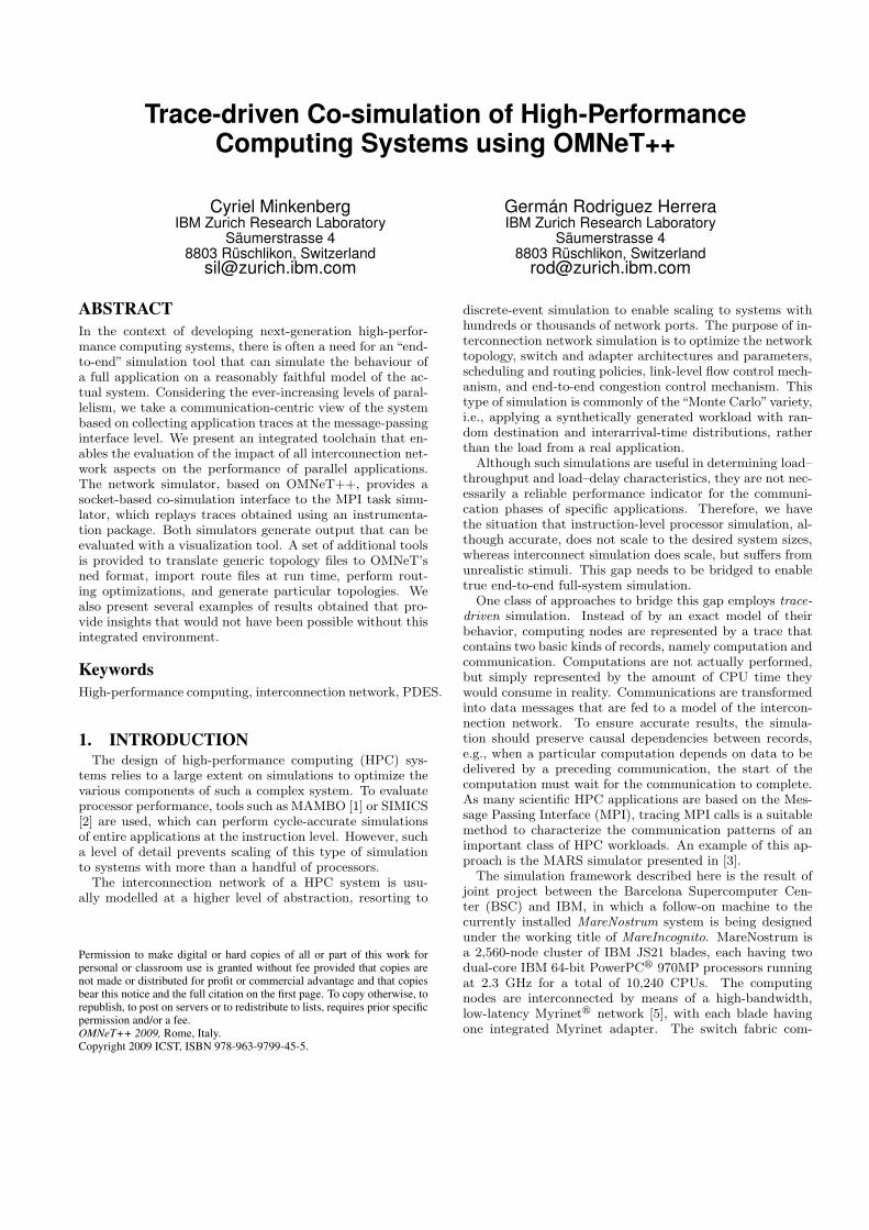
illustrated in Fig. 4. The trace used here is a 256-way WRF
0
2
4
6
8
10
12
14
8-88-7
8-68-5
8-48-3
8-28-1
7-77-6
7-57-4
7-37-2
7-16-7
6-66-5
6-46-3
6-26-1
5-55-4
5-35-2
5-14-4
4-34-2
4-13-3
3-23-1
2-22-1
1-1
Tim
e / (
Tim
e Ful
l Cro
ssba
r)
# of middle switches in the upper Switching Levels
WRF, Progressive tree-slimming
Full-CrossbarNaiveRandomMod-kBruteforceColored
Figure 3: Performance of 256-node WRF onslimmed 3-level XGFTs.
(weather research and forecast) pattern on a two-level fat-tree network, in which each node n first sends one messageto node n + 16 and then one message to node n − 16. Theexceptions are nodes 0–15, which only send to n + 16 andnodes 240–255, which only send to n− 16.
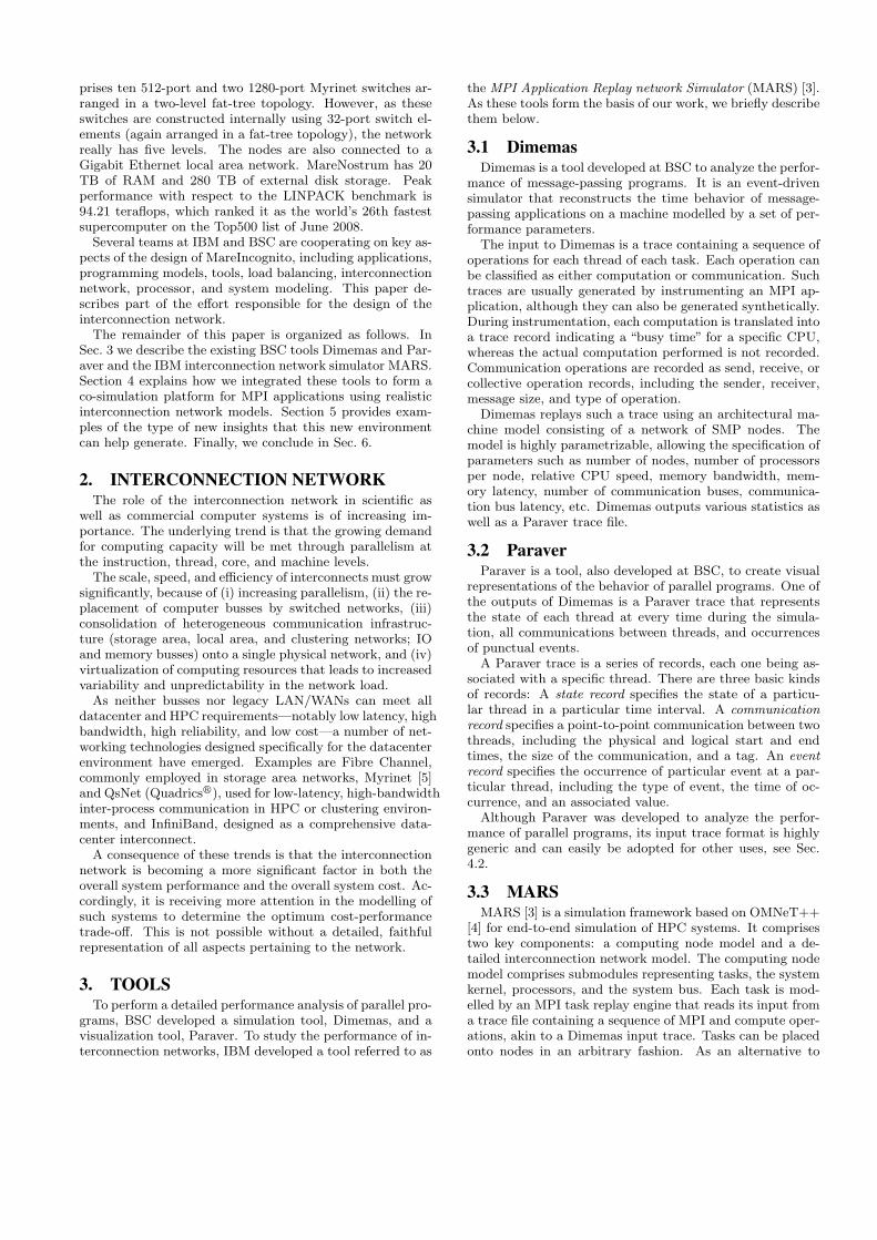
Most nodes completed after about 63 µs, whereas threenodes took 24 µs longer than the rest (circled in Fig. 4).Deep inspection of the Paraver traces revealed that this wascaused by head-of-line blocking: In the first phase, the last16 nodes caused destination contention between communi-cations from, e.g., nodes 253 and 221 to node 237. The mes-sage from 253 was served first, forcing the message from 221to wait. The first message from node 221 was still blockedwhen the second message (to node 205) arrived on the sameinput port of the second-level crossbar: this second messagewas HOL blocked! The same thing happened for messagesfrom two other nodes. Additional instrumentation to ex-plicitly detect HOL-blocking yielded the results shown inFig. 5, which shows the affected ports on all 16 second-levelswitches. Three switches exhibit HOL blocking; it turnedout that this depends on the initial setting of the round-robin pointer used by the switches to select which port toserve in case of contention. As these pointers were initial-ized randomly, blocking occurred on only a few ports. Byinitially setting all pointer to the same value, we were ableto induce blocking on all or none of the ports. Simulationswith an output-queued switch architecture did not exhibitthis behavior, as expected.
6. CONCLUSIONWe presented a communication-centric simulation envi-
ronment for HPC systems based on trace-driven co-simulationbetween an MPI task simulator and a detailed network sim-ulator. This combination builds on the strengths of thesetwo tools—and of an array of auxiliary ones—to enable athorough exploration of the impact of the interconnectionnetwork on parallel application performance with an un-precedented accuracy, depth, and flexibility. Moreover, theextension of the visualization part of the toolchain to incor-porate network communications, states, and events providesa new level of evaluation power.
The purpose of the environment is to aid the design of
Figure 4: 256-way WRF pattern; communicationamong threads.
Figure 5: 256-way WRF pattern; HOL blocking onL2 switch ports.
next-generation HPC machines. We presented some exam-ples of the kinds of insight the new environment can provide.Most notably, these insights range across all four levels: ap-plication, MPI library, topology, and hardware. We expectthese insights to help point the way towards scalable, cost-effective, yet high-performance interconnection networks forthe next generation of supercomputers.
7. REFERENCES[1] Peterson, J. L., Bohrer, P. J., Chen, L., Elnozahy, E.
N., Gheith, A., Jewell, R. H., Kistler, M. D., Maeurer,T. R., Malone, S. A., Murrell, D. B., Needel, N.,Rajamani, K., Rinaldi, M. A., Simpson, R. O., Sudeep,K., Zhang, L. Application of full-system simulation inexploratory system design and development. IBMJournal of Research and Development, Vol. 50, No.2/3, March/May 2006, pp. 321–332.
[2] Magnusson, P. S., Christensson, M., Eskilson, J.,Forsgren, D., Hallberg, G., Hogberg, J., Larsson, F.,Moestedt, A., Werner, B. Simics: A full systemsimulation platform. IEEE Computer, Vol. 35, No. 2,Feb. 2002, pp. 50–58.
[3] Denzel, W. E., Li, J., Walker, P., Jin, Y. A frameworkfor end-to-end simulation of high-performancecomputing systems. In Proceedings of the FirstInternational Conference on Simulation Tools andTechniques for Communications, Networks andSystems (SIMUTools 2008), Marseille, France, March3–7, 2008, article No. 21..
[4] Varga, A. The OMNeT++ discrete event simulationsystem. In Proceedings of the European SimulationMulticonference (ESM’ 01), Prague, Czech Republic,June 2001.
[5] Boden, N. J., Cohen, D., Felderman, R. E., Kulawik,A. E., Seitz, C. L., Seizovic, J. N., Su, W.-K. Myrinet:A gigabit-per-second local area network. IEEE Micro,Vol. 15, No. 1, 1995, pp. 29–36.
[6] Petrini, F., Vanneschi, M. k-ary n-trees:High-performance networks for massively parallelarchitectures. In Proceedings of the 11th InternationalSymposium on Parallel Processing (IPPS ’97), Apr.1–5, 1997, Geneva, Switzerland, pp. 87–93.
[7] Desai, N., Balaji, P., Sadayappan, P., Islam, M. Arenonblocking networks really needed forhigh-end-computing workloads? In Proceedings of the2008 IEEE International Conference on ClusterComputing (Cluster ’08), Tsukuba, Japan, Sep.29–Oct. 1, 2008, pp. 152–159.
[8] Ohring, S., Ibel, M., Das, S. K., Kumar, M. J. Ongeneralized fat trees. In Proceedings of the 9thInternational Symposium on Parallel Processing (IPPS’95), Santa Barbara, CA, April 25–28, 1995, pp. 37–44.
[9] Geoffray, P., Hoefler, T. Adaptive routing strategiesfor modern high performance networks. In Proceedingsof the 16th IEEE Symposium on High PerformanceInterconnects (HOTI ’08), Stanford, CA, Aug. 27–28,2008, pp. 165–172.
[10] Bagrodia, R., Takai, M. Performance evaluation ofconservative algorithms in parallel simulationlanguages. IEEE Transactions Parallel DistributedSystems, Vol. 11, No. 4, 2000, pp. 395–411.
[11] Varga, A., Sekercioglu, Y. A., Egan, G. K. A practicalefficiency criterion for the null message algorithm. InProceedings of the European Simulation Symposium(ESS 2003), Oct. 26–29, 2003, Delft, The Netherlands.