tr fastenings tr hank self clinch fastenersindustrialfasteners.bg/data/ufiles/catalog/brochures/tr...
TRANSCRIPT

TR FASTENINGSTR Hank® Self Clinch Fasteners
SPECIFY • MANUFACTURE • DELIVER • INTERNATIONALLY
TR Fastenings is recognised throughout the industry for world-class products and services. We manufacture, stock and distribute a vast range of industrial fasteners and associated components.
Edition 6

Page Page
Flush Head StudsTR-FH | TR-FHS | TR-FH4 |TR-FHA
1 - 2Grounding StandoffsTR-SOSG
17
Flush Head PinsTR-TP | TR-TPS
3NutsTR-S | TR-CLS | TR-CLA | TR-SP4
18 - 19
Hi Strength StudsTR-HFH | TR-HFHS
4 - 5Flush NutsTR-F
20
Low Displacement Flush Head StudsTR-FHL | TR-FHLS
6 - 7Broaching StandoffsTR-KFE | TR-KFSE
21
Concealed Head StudsTR-CHC | TR-CFHC | TR-CHA |TR-CFHA
8 - 9Broaching NutsTR-KF2 | TR-KFS2
22
Concealed Head StandoffsTR-CSOS | TR-CSS
10 - 11Blind NutsTR-B | TR-BS
23
Blind StandoffsTR-BSO | TR-BSOS | TR-BSOA | TR-BSO4
12
Floating Fasteners - Locking & Non-LockingTR-LAS | TR-LAC | TR-AS | TR-AC
24
Through StandoffsTR-SO | TR-SOS | TR-SOA | TR-SO4
13Panel FastenersTR-PFC2 | TR-PFS2
25
Clip-on StandoffsTR-SSS | TR-SSC | TR-SSA
14Recess Panel FastenersTR-PFC2P
26
Screw Lock Threaded StandoffsTR-DSO | TR-DSOS
15Low Profile Panel FastenersTR-PF31 | TR-PF32
27
Hole Slide Lock StandoffsTR-SKC
16 Installation Guides 28-33
Contents
TR Hank® Self-Clinch

1
Metric Dimensions
Thread size M2 M2.5 M3 M3.5 M4 M5 M6 M8
D ±0.4 3.5 4.1 4.6 5.3 5.9 6.5 8.2 9.6
H max 1.95 1.95 2.1 2.2 2.4 2.7 3.0 3.7
Min sheet thickness 1 1 1 1 1 1 1.6 2.4
Hole +0.08 -0.0 2 2.5 3.0 3.5 4.0 5.0 6.0 8.0
Min distance to edge of sheet 5.2 5.4 5.6 6.4 7.2 7.2 7.9 9.6
TR Hank® Self-Clinch Flush Head Studs
Preferred Range
Thread size x Pitch M2 x 0.4 M2.5 x 0.45 M3 x 0.5 M3.5 x 0.6 M4 x 0.7 M5 x 0.8 M6 x 1.0 M8 x 1.25
Length ±0.4
5 •6 • • • •8 • • • • • • •10 • • • • • • • •12 • • • • • • • •15 • • • • • • • •16 • • • • • • •18 • • • • • • •20 • • • • • • •22 • • • • •25 • • • • •28 • • • •30 • • • • •35 • • • • •38 • • • •40 • • • •45 • • •50 • • • •
D
H
L
Plated Steel : TR-FH | Stainless Steel : TR-FHS | 400 Series Stainless Steel : TR-FH4 |*Aluminium Alloy : TR-FHA
2
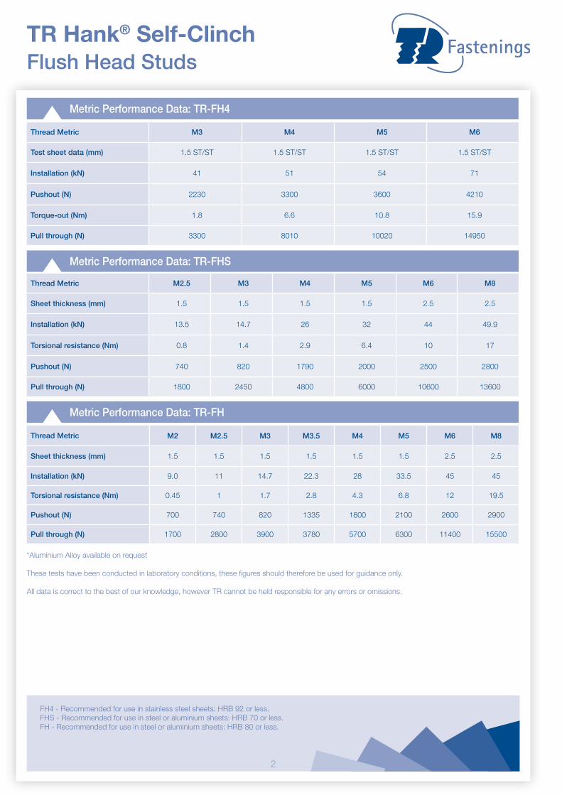
Metric Performance Data: TR-FH4
TR Hank® Self-Clinch Flush Head Studs
Metric Performance Data: TR-FH
Thread Metric M2 M2.5 M3 M3.5 M4 M5 M6 M8
Sheet thickness (mm) 1.5 1.5 1.5 1.5 1.5 1.5 2.5 2.5
Installation (kN) 9.0 11 14.7 22.3 28 33.5 45 45
Torsional resistance (Nm) 0.45 1 1.7 2.8 4.3 6.8 12 19.5
Pushout (N) 700 740 820 1335 1800 2100 2600 2900
Pull through (N) 1700 2800 3900 3780 5700 6300 11400 15500
Metric Performance Data: TR-FHS
Thread Metric M2.5 M3 M4 M5 M6 M8
Sheet thickness (mm) 1.5 1.5 1.5 1.5 2.5 2.5
Installation (kN) 13.5 14.7 26 32 44 49.9
Torsional resistance (Nm) 0.8 1.4 2.9 6.4 10 17
Pushout (N) 740 820 1790 2000 2500 2800
Pull through (N) 1800 2450 4800 6000 10600 13600
Thread Metric M3 M4 M5 M6
Test sheet data (mm) 1.5 ST/ST 1.5 ST/ST 1.5 ST/ST 1.5 ST/ST
Installation (kN) 41 51 54 71
Pushout (N) 2230 3300 3600 4210
Torque-out (Nm) 1.8 6.6 10.8 15.9
Pull through (N) 3300 8010 10020 14950
*Aluminium Alloy available on request
These tests have been conducted in laboratory conditions, these figures should therefore be used for guidance only.
All data is correct to the best of our knowledge, however TR cannot be held responsible for any errors or omissions.
FH4 - Recommended for use in stainless steel sheets: HRB 92 or less.FHS - Recommended for use in steel or aluminium sheets: HRB 70 or less.FH - Recommended for use in steel or aluminium sheets: HRB 80 or less.

3
Zinc Plated Steel : TR-TP | Stainless Steel : TR-TPS
Metric Dimensions
Pin diameter+/- 0.05
Min sheetthickness
Hole size in sheet + 0.08
D +/- 0.4
Hmax
Min. distancehole C/L to edge
3mm 1 3.5 5.20 2.29 6.4
4mm 1 4.5 6.12 2.29 7.1
5mm 1 5.5 7.19 2.29 7.6
6mm 1 6.5 8.13 2.29 7.9
TR Hank® Self-Clinch Flush Head Pins
Metric Performance Data: TR-TP
Pin diameter code 3mm 4mm 5mm 6mm
Test sheet material Steel Steel Steel Steel
Installation (kN) 23 27 35 40
Pushout (kN) 1 1.6 1.8 2.2
64
L
D
H
d
Preferred Range
Pin diameter P±0.05 3 4 5 6
Length ±0.4
6 •8 • • •10 • • • •12 • • • •16 • • • •20 • • •
These tests have been conducted in laboratory conditions, these figures should therefore be used for guidance only.
All data is correct to the best of our knowledge, however TR cannot be held responsible for any errors or omissions.
TPS - Recommended for use in sheet hardness: HRB 70
4
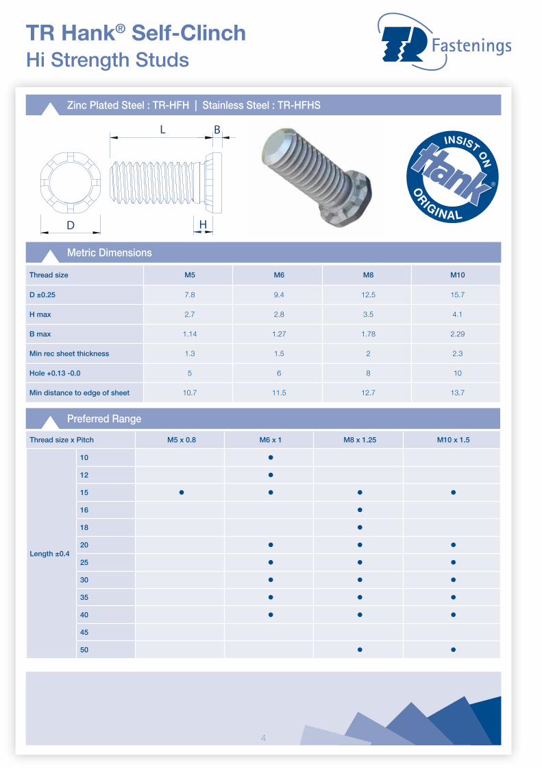
Zinc Plated Steel : TR-HFH | Stainless Steel : TR-HFHS
Metric Dimensions
Thread size M5 M6 M8 M10
D ±0.25 7.8 9.4 12.5 15.7
H max 2.7 2.8 3.5 4.1
B max 1.14 1.27 1.78 2.29
Min rec sheet thickness 1.3 1.5 2 2.3
Hole +0.13 -0.0 5 6 8 10
Min distance to edge of sheet 10.7 11.5 12.7 13.7
TR Hank® Self-Clinch Hi Strength Studs
D
BL
H
Preferred Range
Thread size x Pitch M5 x 0.8 M6 x 1 M8 x 1.25 M10 x 1.5
Length ±0.4
10 •12 •15 • • • •16 •18 •20 • • •25 • • •30 • • •35 • • •40 • • •45
50 • •

5
Metric Performance Data: TR-HFH
Thread M5 M6 M8 M10
Test sheet thicknessAluminium
1.5 1.5 2.3 2.4Steel
Test sheet hardness (HRB)Aluminium 15 43 39 39
Steel 65 59 58 58
Installation (kN)Aluminium 14 30 36 41
Steel 27 34 45 55
Pushout (N)Aluminium 805 1280 1750 2450
Steel 1550 1780 2210 3475
Torque-out (Nm)Aluminium 5.4 14.5 30.1 36
Steel 7.7 14.5 30.1 49.5
TR Hank® Self-Clinch Hi Strength Studs
Metric Performance Data: TR-HFHS
Thread M5 M6 M8 M10
Test sheet thicknessAluminium 1.62 1.62 2.23 2.3
Steel 1.5 1.6 2.48 2.3
Test sheet hardness (HRB)Aluminium 35 35 44 44
Steel 54 45 43 44
Installation (kN)Aluminium 13 15.5 24.5 34
Steel 22.5 25 38 47
Pushout (N)Aluminium 805 1280 1700 2450
Steel 1505 1780 2200 3500
Torque-out (Nm)Aluminium 5.4 11.5 21 36.5
Steel 6.5 11.5 21 36.5
These tests have been conducted in laboratory conditions, these figures should therefore be used for guidance only.
All data is correct to the best of our knowledge, however TR cannot be held responsible for any errors or omissions.
HFH - Recommended for use in steel or aluminium sheets: HRB 85 or less.HFHS - Recommended for use in steel or aluminium sheets: HRB 70 or less.

6
Zinc Plated Steel : TR-FHL | Stainless Steel : TR-FHLS
Metric Dimensions
Thread size M2.5 M3 M4 M5
D ±0.4 3.15 3.65 4.65 5.9
H max 2.1 2.1 2.4 2.7
Min sheet thickness 1 1 1 1
Hole +0.08 2.5 3 4 5
Min distance to edge of sheet 2.8 3.3 4.3 5.6
TR Hank® Self-Clinch Low Displacement Flush Head Studs
D
L
H
Preferred Range
Thread size M2.5 M3 M4 M5
Length ±0.4
6 • • •8 • • •10 • • • •12 • • • •15 • • • •18 • • •20 • • •25 •30 •35
These tests have been conducted in laboratory conditions, these figures should therefore be used for guidance only.
All data is correct to the best of our knowledge, however TR cannot be held responsible for any errors or omissions.
7
TR Hank® Self-Clinch Low Displacement Flush Head Studs
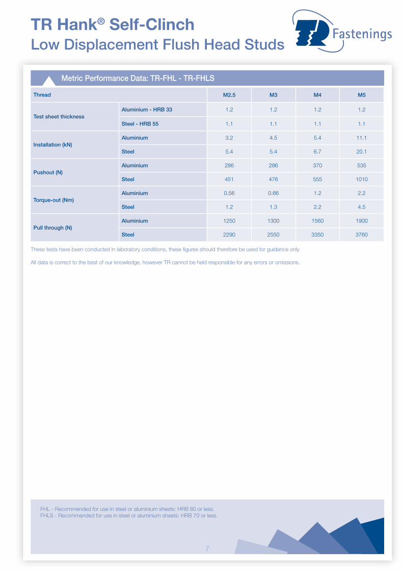
Metric Performance Data: TR-FHL - TR-FHLS
Thread M2.5 M3 M4 M5
Test sheet thicknessAluminium - HRB 33 1.2 1.2 1.2 1.2
Steel - HRB 55 1.1 1.1 1.1 1.1
Installation (kN)Aluminium 3.2 4.5 5.4 11.1
Steel 5.4 5.4 6.7 20.1
Pushout (N)Aluminium 286 286 370 535
Steel 451 476 555 1010
Torque-out (Nm)Aluminium 0.56 0.66 1.2 2.2
Steel 1.2 1.3 2.2 4.5
Pull through (N)Aluminium 1250 1300 1560 1900
Steel 2290 2550 3350 3760
These tests have been conducted in laboratory conditions, these figures should therefore be used for guidance only.
All data is correct to the best of our knowledge, however TR cannot be held responsible for any errors or omissions.
FHL - Recommended for use in steel or aluminium sheets: HRB 80 or less.FHLS - Recommended for use in steel or aluminium sheets: HRB 70 or less.
8
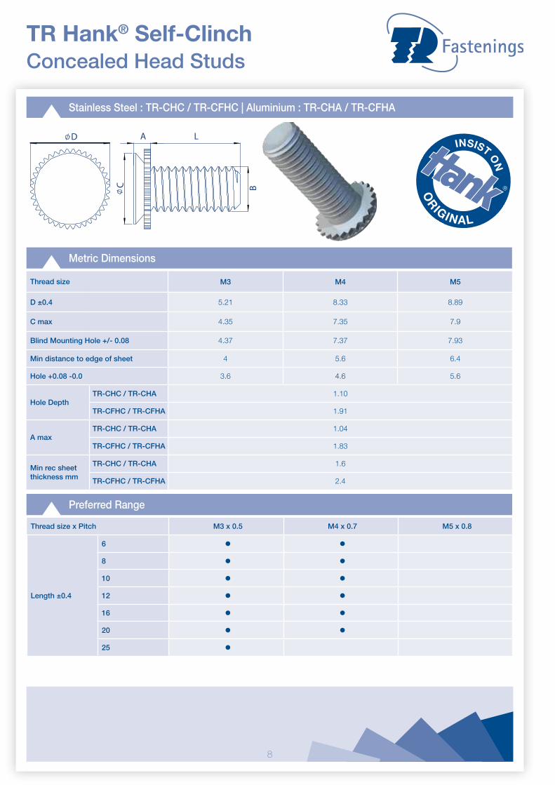
Thread size M3 M4 M5
D ±0.4 5.21 8.33 8.89
C max 4.35 7.35 7.9
Blind Mounting Hole +/- 0.08 4.37 7.37 7.93
Min distance to edge of sheet 4 5.6 6.4
Hole +0.08 -0.0 3.6 4.6 5.6
Hole DepthTR-CHC / TR-CHA 1.10
TR-CFHC / TR-CFHA 1.91
A maxTR-CHC / TR-CHA 1.04
TR-CFHC / TR-CFHA 1.83
Min rec sheet thickness mm
TR-CHC / TR-CHA 1.6
TR-CFHC / TR-CFHA 2.4
Stainless Steel : TR-CHC / TR-CFHC | Aluminium : TR-CHA / TR-CFHA
Metric Dimensions
TR Hank® Self-Clinch Concealed Head Studs
Preferred Range
Thread size x Pitch M3 x 0.5 M4 x 0.7 M5 x 0.8
Length ±0.4
6 • •8 • •10 • •12 • •16 • •20 • •25 •
D LA
C B

9
Thread x Pitch M3 x 0.5 M4 x 0.7 M5 x 0.8
Installation Cold Rolled Steel (kN)
Stainless Steel: TR-CHC 8 17.8 22.2
Stainless Steel: TR-CFHC 8.9 14.7 17.8
Installation Aluminium Sheet(kN)
Aluminium: TR-CHA 6.2 12.5 17.8
Aluminium: TR-CFHA 6.7 13.3 15.6
Pushout (N)
Stainless Steel: TR-CHC 1065 1200 1290
Stainless Steel: TR-CFHC 1065 1955 3020
Aluminium: TR-CHA 555 645 755
Aluminium: TR-CFHA 845 1065 1330
Max Tightening Torque
Stainless Steel: TR-CHC 0.5 2 3.6
Stainless Steel: TR-CFHC 0.5 2 3.6
Aluminium: TR-CHA 0.3 1.2 2.16
Aluminium: TR-CFHA 0.3 1.2 2.16
Performance Data
TR Hank® Self-Clinch Concealed Head Studs
Please note:TR-CHC & TR-CHA: To suit 1.6mm sheetTR-CFHC & TR-CFHA: To suit 2.4mm sheet
These tests have been conducted in laboratory conditions, these figures should therefore be used for guidance only.
All data is correct to the best of our knowledge, however TR cannot be held responsible for any errors or omissions.
10
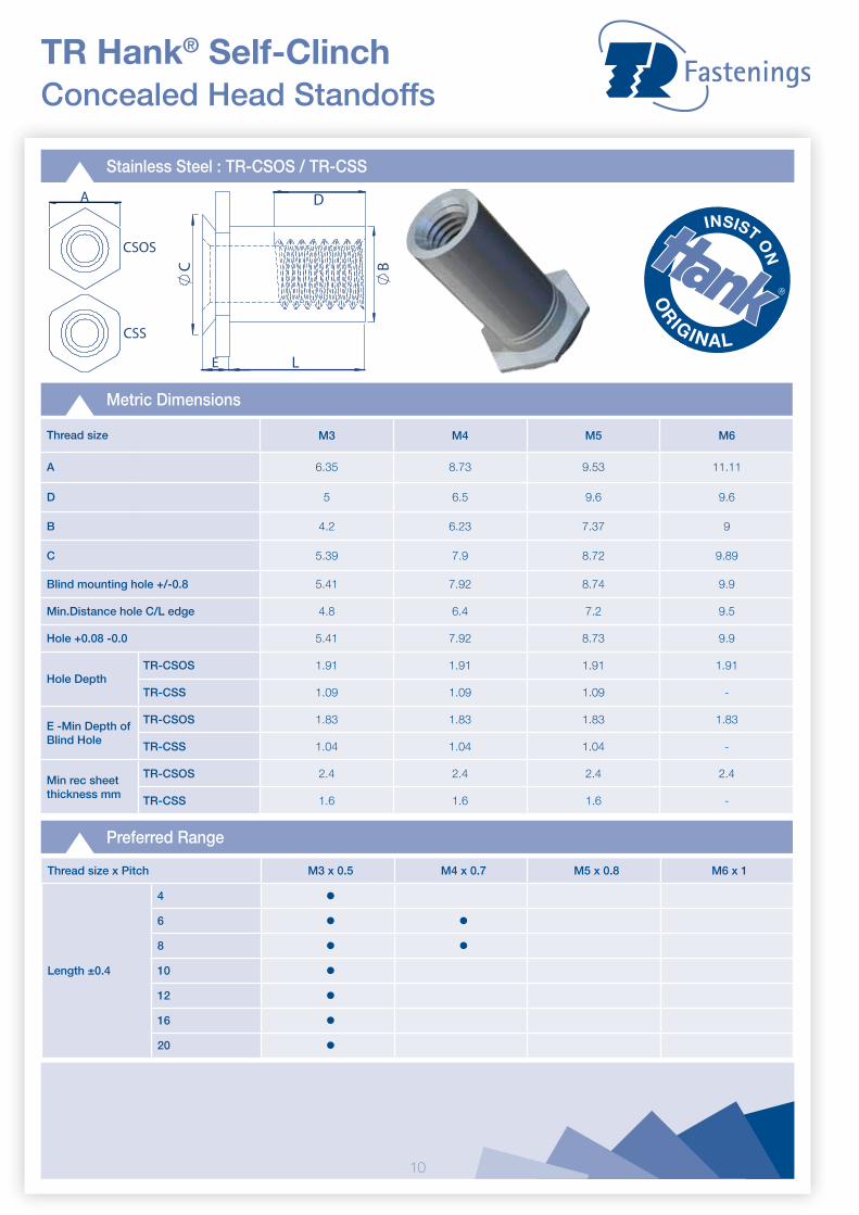
Thread size M3 M4 M5 M6
A 6.35 8.73 9.53 11.11
D 5 6.5 9.6 9.6
B 4.2 6.23 7.37 9
C 5.39 7.9 8.72 9.89
Blind mounting hole +/-0.8 5.41 7.92 8.74 9.9
Min.Distance hole C/L edge 4.8 6.4 7.2 9.5
Hole +0.08 -0.0 5.41 7.92 8.73 9.9
Hole DepthTR-CSOS 1.91 1.91 1.91 1.91
TR-CSS 1.09 1.09 1.09 -
E -Min Depth of Blind Hole
TR-CSOS 1.83 1.83 1.83 1.83
TR-CSS 1.04 1.04 1.04 -
Min rec sheet thickness mm
TR-CSOS 2.4 2.4 2.4 2.4
TR-CSS 1.6 1.6 1.6 -
Stainless Steel : TR-CSOS / TR-CSS
Metric Dimensions
TR Hank® Self-Clinch Concealed Head Standoffs
Preferred Range
Thread size x Pitch M3 x 0.5 M4 x 0.7 M5 x 0.8 M6 x 1
Length ±0.4
4 •6 • •8 • •10 •12 •16 •20 •
A
CSOS
CSS
B L
C
D
E

11
Thread x Pitch M3 x 0.5 M4 x 0.7 M5 x 0.8 M6 x 1.0
Installation Cold Rolled Steel (kN)
Stainless Steel: TR-CSS 17.8 21.3 24.5 -
Stainless Steel: TR-CSOS 19.2 23.6 26.7 28.9
Pushout (N)Stainless Steel: TR-CSS 1330 1775 2000 -
Stainless Steel: TR-CSOS 1465 1955 2665 2860
Max Tightening TorqueStainless Steel: TR-CSS 0.55 2 3.6 -
Stainless Steel: TR-CSOS 0.44 1.6 2.9 7.2
Performance Data
TR Hank® Self-Clinch Concealed Head Standoffs
These tests have been conducted in laboratory conditions, these figures should therefore be used for guidance only.
All data is correct to the best of our knowledge, however TR cannot be held responsible for any errors or omissions.
12
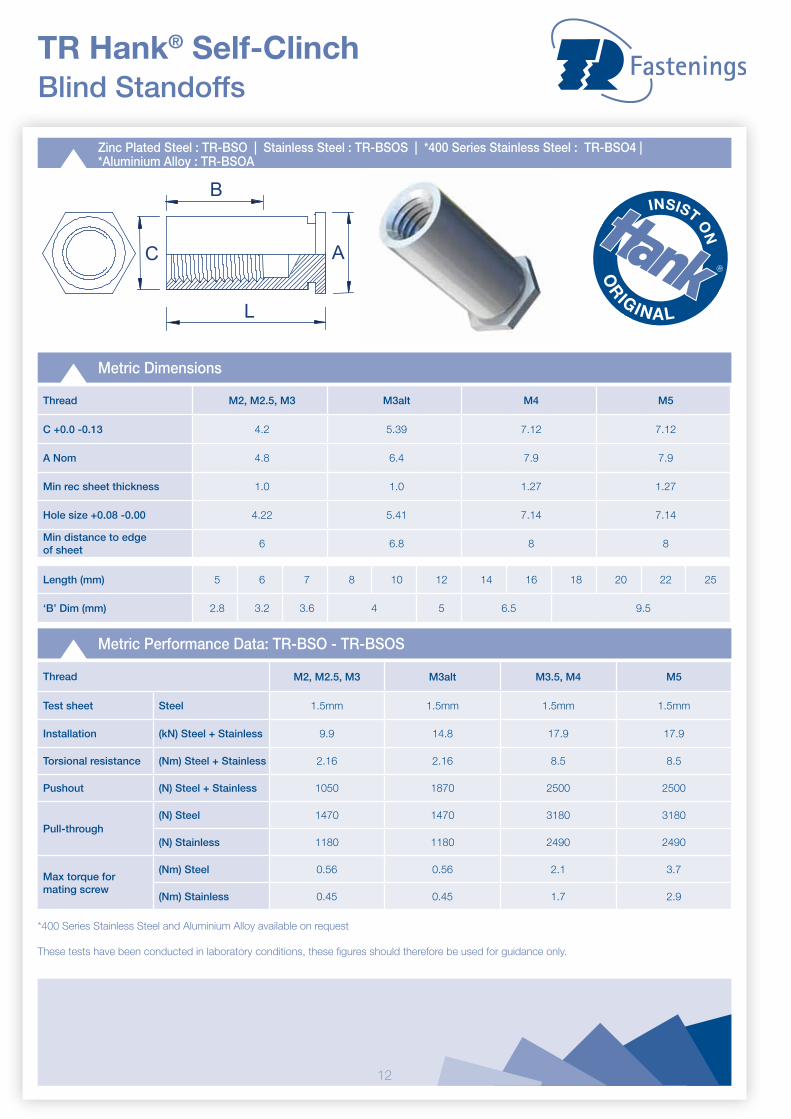
Zinc Plated Steel : TR-BSO | Stainless Steel : TR-BSOS | *400 Series Stainless Steel : TR-BSO4 |*Aluminium Alloy : TR-BSOA
TR Hank® Self-Clinch Blind Standoffs
Metric Dimensions
Thread M2, M2.5, M3 M3alt M4 M5
C +0.0 -0.13 4.2 5.39 7.12 7.12
A Nom 4.8 6.4 7.9 7.9
Min rec sheet thickness 1.0 1.0 1.27 1.27
Hole size +0.08 -0.00 4.22 5.41 7.14 7.14
Min distance to edge of sheet
6 6.8 8 8
Length (mm) 5 6 7 8 10 12 14 16 18 20 22 25
‘B’ Dim (mm) 2.8 3.2 3.6 4 5 6.5 9.5
Metric Performance Data: TR-BSO - TR-BSOS
A
L
B
C
Thread M2, M2.5, M3 M3alt M3.5, M4 M5
Test sheet Steel 1.5mm 1.5mm 1.5mm 1.5mm
Installation (kN) Steel + Stainless 9.9 14.8 17.9 17.9
Torsional resistance (Nm) Steel + Stainless 2.16 2.16 8.5 8.5
Pushout (N) Steel + Stainless 1050 1870 2500 2500
Pull-through(N) Steel 1470 1470 3180 3180
(N) Stainless 1180 1180 2490 2490
Max torque for mating screw
(Nm) Steel 0.56 0.56 2.1 3.7
(Nm) Stainless 0.45 0.45 1.7 2.9
*400 Series Stainless Steel and Aluminium Alloy available on request
These tests have been conducted in laboratory conditions, these figures should therefore be used for guidance only.
13
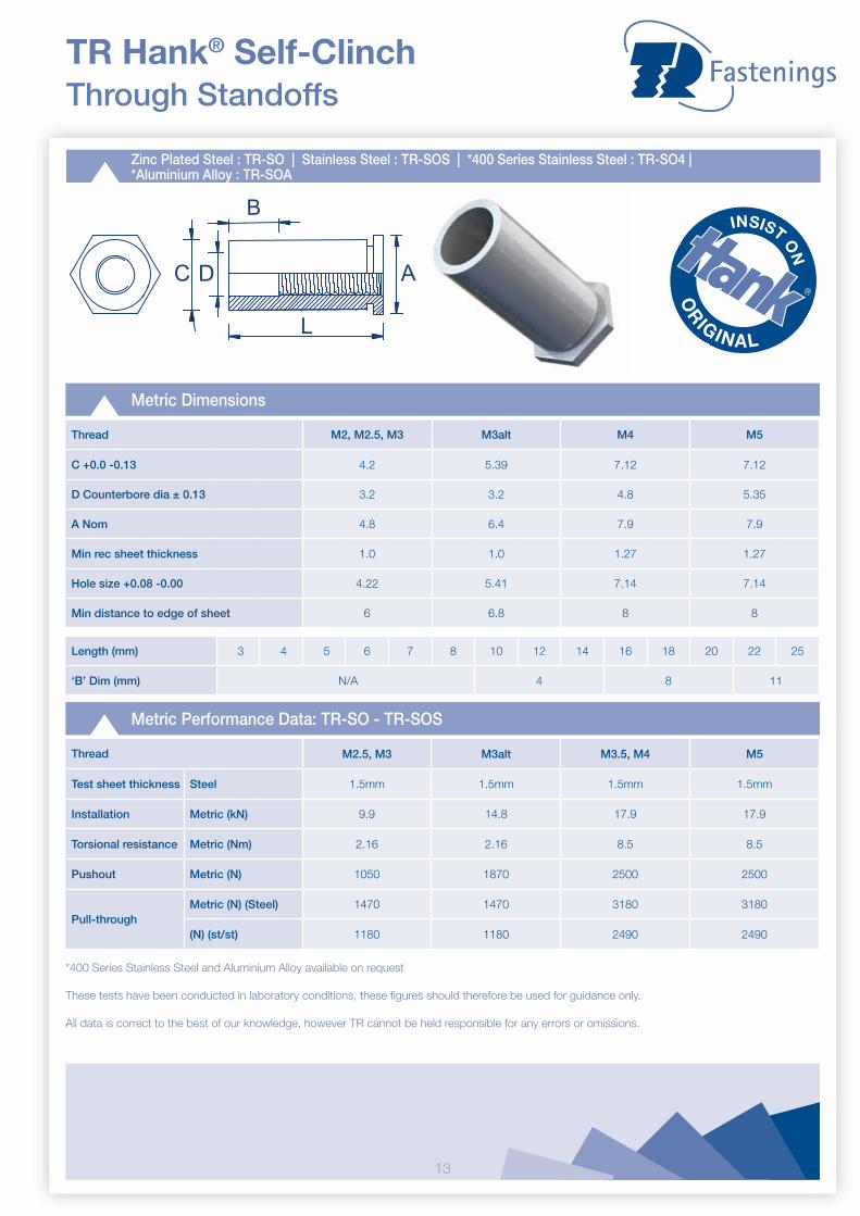
Zinc Plated Steel : TR-SO | Stainless Steel : TR-SOS | *400 Series Stainless Steel : TR-SO4 | *Aluminium Alloy : TR-SOA
TR Hank® Self-Clinch Through Standoffs
A
L
B
C D
Metric Dimensions
Thread M2, M2.5, M3 M3alt M4 M5
C +0.0 -0.13 4.2 5.39 7.12 7.12
D Counterbore dia ± 0.13 3.2 3.2 4.8 5.35
A Nom 4.8 6.4 7.9 7.9
Min rec sheet thickness 1.0 1.0 1.27 1.27
Hole size +0.08 -0.00 4.22 5.41 7.14 7.14
Min distance to edge of sheet 6 6.8 8 8
Length (mm) 3 4 5 6 7 8 10 12 14 16 18 20 22 25
‘B’ Dim (mm) N/A 4 8 11
Metric Performance Data: TR-SO - TR-SOS
Thread M2.5, M3 M3alt M3.5, M4 M5
Test sheet thickness Steel 1.5mm 1.5mm 1.5mm 1.5mm
Installation Metric (kN) 9.9 14.8 17.9 17.9
Torsional resistance Metric (Nm) 2.16 2.16 8.5 8.5
Pushout Metric (N) 1050 1870 2500 2500
Pull-throughMetric (N) (Steel) 1470 1470 3180 3180
(N) (st/st) 1180 1180 2490 2490
*400 Series Stainless Steel and Aluminium Alloy available on request
These tests have been conducted in laboratory conditions, these figures should therefore be used for guidance only.
All data is correct to the best of our knowledge, however TR cannot be held responsible for any errors or omissions.
14
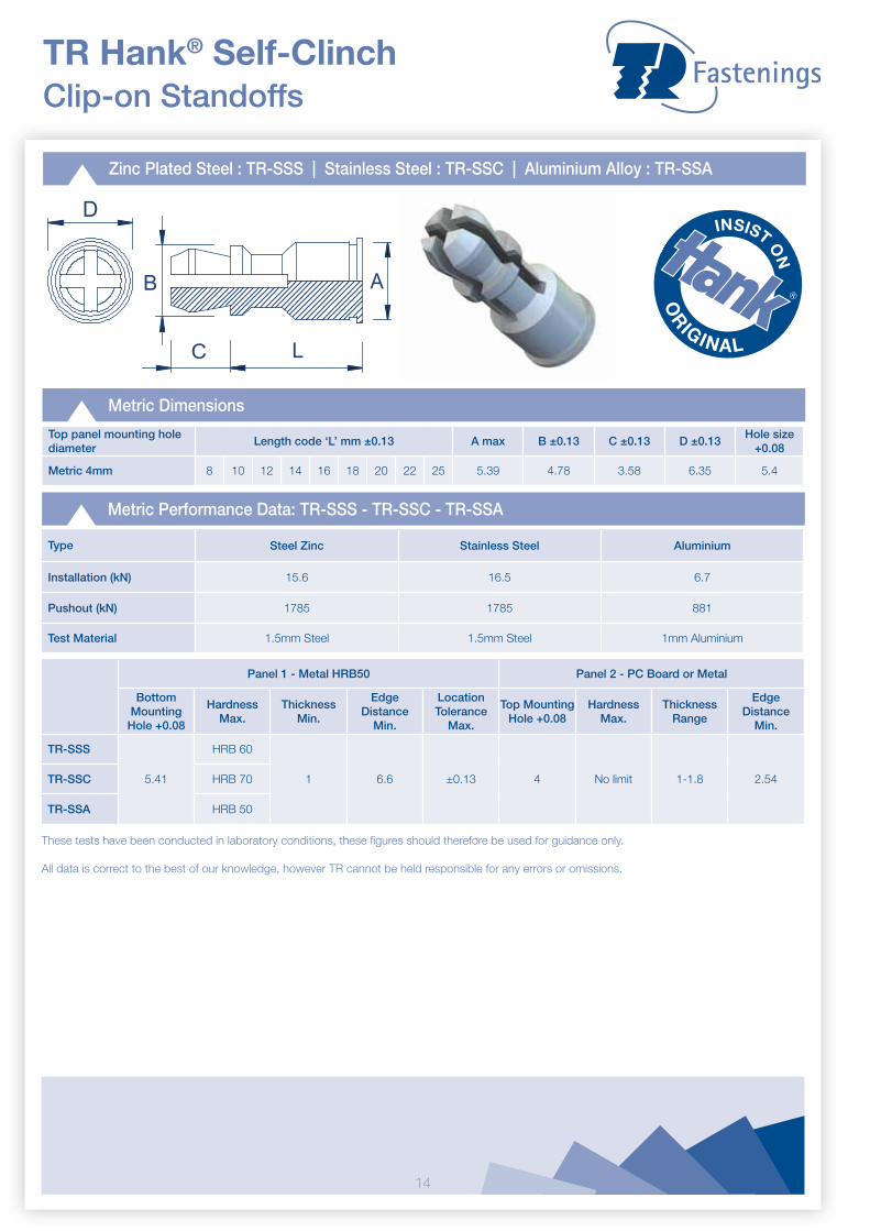
Zinc Plated Steel : TR-SSS | Stainless Steel : TR-SSC | Aluminium Alloy : TR-SSA
TR Hank® Self-Clinch Clip-on Standoffs
D
B
C L
A
Metric Dimensions
Top panel mounting holediameter
Length code ‘L’ mm ±0.13 A max B ±0.13 C ±0.13 D ±0.13Hole size
+0.08
Metric 4mm 8 10 12 14 16 18 20 22 25 5.39 4.78 3.58 6.35 5.4
Metric Performance Data: TR-SSS - TR-SSC - TR-SSA
Type Steel Zinc Stainless Steel Aluminium
Installation (kN) 15.6 16.5 6.7
Pushout (kN) 1785 1785 881
Test Material 1.5mm Steel 1.5mm Steel 1mm Aluminium
Panel 1 - Metal HRB50 Panel 2 - PC Board or Metal
Bottom Mounting
Hole +0.08
Hardness Max.
Thickness Min.
Edge Distance
Min.
Location Tolerance
Max.
Top Mounting Hole +0.08
Hardness Max.
Thickness Range
Edge Distance
Min.
TR-SSS
5.41
HRB 60
1 6.6 ±0.13 4 No limit 1-1.8 2.54TR-SSC HRB 70
TR-SSA HRB 50
These tests have been conducted in laboratory conditions, these figures should therefore be used for guidance only.
All data is correct to the best of our knowledge, however TR cannot be held responsible for any errors or omissions.

15
TR Hank® Self-Clinch Screw Lock Threaded Standoffs
Zinc Plated Steel : TR-DSO | Stainless Steel : TR-DSOS
D L
C
Metric Dimensions
Thread M3
L +0.05 -0.136.35
7
C max 4.2
D nom 4.92
Sheet thickness 0.94 - 6.35
Hole +0.08 4.2
Min distance to edge of sheet 3.2
Metric Performance Data: TR-DSO - TR-DSOS
Thread M3
Sheet thickness (mm)Steel 1
Aluminium 1
Installation (kN)Steel 5.85
Aluminium 4.5
Pushout (N)Steel 334
Aluminium 225
Torsional Resistance (Nm)Steel 1.2
Aluminium 1.1
These tests have been conducted in laboratory conditions, these figures should therefore be used for guidance only.
All data is correct to the best of our knowledge, however TR cannot be held responsible for any errors or omissions.
16
Panel 1 - Metal HRB50 Panel 2 - PC Board or Metal
Bottom Mounting
Hole +0.08
Hardness Max.
Thickness Min.
Edge Distance
Min.
Location Tolerance
Max.
Top Mounting Hole +0.08Thickness
Range
Edge Distance
Min.A1 Nom.
A2 ±0.08
A3±0.08
A4Min.
TR-SKC 5.4 HRB 70 1 6.6 ±0.13 1.5 3 5 3.75 1.45-1.62 4.1
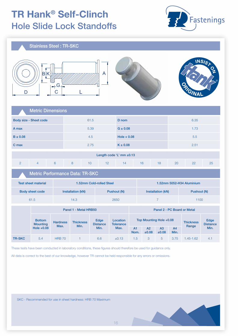
TR Hank® Self-Clinch Hole Slide Lock Standoffs
Stainless Steel : TR-SKC
D LC
G
AB K
Metric Dimensions
Body size - Sheet code 61.5 D nom 6.35
A max 5.39 G ± 0.08 1.73
B ± 0.08 4.5 Hole + 0.08 5.5
C max 2.75 K ± 0.08 2.51
Metric Performance Data: TR-SKC
Test sheet material 1.52mm Cold-rolled Steel 1.52mm 5052-H34 Aluminium
Body sheet code Installation (kN) Pushout (N) Installation (kN) Pushout (N)
61.5 14.3 2650 7 1100
These tests have been conducted in laboratory conditions, these figures should therefore be used for guidance only.
All data is correct to the best of our knowledge, however TR cannot be held responsible for any errors or omissions.
SKC - Recommended for use in sheet hardness: HRB 70 Maximum
Length code ‘L’ mm ±0.13
2 4 6 8 10 12 14 16 18 20 22 25

17
TR Hank® Self-Clinch Grounding Standoffs
Stainless Steel : TR-SOSG
H A/F L P
C
Metric Dimensions
Metric Performance Data: TR-SOSG
These tests have been conducted in laboratory conditions, these figures should therefore be used for guidance only.
All data is correct to the best of our knowledge, however TR cannot be held responsible for any errors or omissions.
Thread M3
C +0.0 -0.13 5.39
H Nom 6.4
Min rec sheet thickness 1
Knurling 0.76
Hole size +0.08 -0.00 5.4
Min distance to edge of sheet 6.8
Thread Size x Pitch
Type Length code ‘L’ mm ±0.13
M3 x 0.5 TR-SOSG 3 4 6 8 10 12

18
D B
h
H
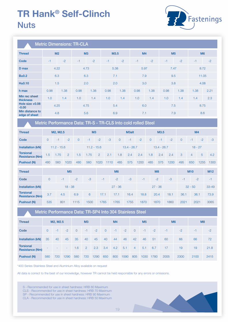
TR Hank® Self-Clinch Nuts
Metric Dimensions: TR-S - TR-CLS - TR-SP4
Thread M2, M2.5, M3 M3alt M3.5 M4
Code -0 -1 -2 -3 -0 -1 -2 -0 -1 -2 -0 -1 -2 -3
D max 4.20 4.73 4.73 5.38
B±0.2 6.35 7.1 7.1 7.95
H±0.10 1.5 1.5 1.5 2.0
h max 0.77 0.97 1.38 2.21 0.77 0.97 1.38 0.77 0.97 1.38 0.77 0.97 1.38 2.21
Min rec sheet thickness
0.8 1.0 1.4 2.3 0.8 1.0 1.4 0.8 1.0 1.4 0.8 1.0 1.4 2.3
Hole size +0.08 -0.00
4.22 4.75 4.75 5.41
Min distance to edge of sheet
4.08 5.6 5.6 6.9
Zinc Plated Steel : TR-S | Stainless Steel : TR-CLS | *400 Series Stainless Steel : TR-SP4 | *Aluminium Alloy : TR-CLA |
Thread M5 M6 M8 M10 M12
Code -0 -1 -2 -3 0 -1 -2 -3 -1 -2 -3 -1 -2 -1
D max 6.33 8.73 10.47 13.97 16.95
B±0.2 8.75 11.10 12.65 17.35 20.55
H±0.10 2.0 4.08 5.47 7.48 8.5
h max 0.77 0.97 1.38 2.21 1.15 1.38 2.21 3.05 1.38 2.21 3.05 2.21 3.05 3.05
Min rec sheet thickness
0.8 1.0 1.4 2.3 1.2 1.4 2.3 3.2 1.4 2.3 3.2 2.31 3.18 3.18
Hole size +0.08 -0.00
6.35 8.75 10.5 14.0 17
Min distance to edge of sheet
7.1 8.6 9.7 13.5 16
19
Metric Performance Data: TR-SP4 Into 304 Stainless Steel
Thread M2, M2.5 M3 M4 M5 M6 M8
Code 0 -1 -2 0 -1 -2 0 -1 -2 0 -1 -2 -1 -2 -1 -2
Installation (kN) 35 40 45 35 40 45 40 44 46 42 46 51 60 66 66 72
Torsional Resistance (Nm)
- - - 1.6 2 2.3 3.4 4.2 5.1 4 5.1 6.7 17 19 19 21.8
Pushout (N) 580 720 1290 580 720 1290 650 800 1590 805 1030 1780 2005 2300 2100 2415
Metric Dimensions: TR-CLA
TR Hank® Self-Clinch Nuts
*400 Series Stainless Steel and Aluminium Alloy available on request
All data is correct to the best of our knowledge, however TR cannot be held responsible for any errors or omissions.
Metric Performance Data: TR-S - TR-CLS Into cold rolled Steel
Thread M2, M2.5 M3 M3alt M3.5 M4
Code 0 -1 -2 0 -1 -2 -3 0 -1 -2 0 -1 -2 0 -1 -2 -3
Installation (kN) 11.2 - 15.6 11.2 - 15.6 13.4 - 26.7 13.4 - 26.7 18 - 27
Torsional Resistance (Nm)
1.5 1.75 2 1.5 1.75 2 2.1 1.8 2.4 2.4 1.8 2.4 2.4 3 4 5 4.2
Pushout (N) 480 560 1020 480 560 1020 1110 485 575 1200 485 575 1200 495 650 1255 1300
S - Recommended for use in sheet hardness: HRB 80 MaximumCLS - Recommended for use in sheet hardness: HRB 70 MaximumSP - Recommended for use in sheet hardness: HRB 90 MaximumCLA - Recommended for use in sheet hardness: HRB 50 Maximum
Thread M2 M3 M3.5 M4 M5 M6
Code -1 -2 -1 -2 -1 -2 -1 -2 -1 -2 -1 -2
D max 4.22 4.73 5.38 5.97 7.47 8.72
B±0.2 6.3 6.3 7.1 7.9 9.5 11.05
H±0.10 1.5 2.0 2.0 3.0 3.8 4.08
h max 0.98 1.38 0.98 1.38 0.98 1.38 0.98 1.38 0.98 1.38 1.38 2.21
Min rec sheet thickness
1.0 1.4 1.0 1.4 1.0 1.4 1.0 1.4 1.0 1.4 1.4 2.3
Hole size +0.08 -0.00
4.25 4.75 5.4 6.0 7.5 8.75
Min distance to edge of sheet
4.8 5.6 6.9 7.1 7.9 8.6
Thread M5 M6 M8 M10 M12
Code 0 -1 -2 -3 -1 -2 -3 -1 -2 -3 -1 -2 -1
Installation (kN) 18 - 38 27 - 36 27 - 36 32 - 50 33-49
Torsional Resistance (Nm)
3.7 4.5 6.9 6 17.1 17.1 16.4 18.8 20.4 18.1 36.1 36.1 73.9
Pushout (N) 535 801 1115 1500 1765 1765 1755 1870 1870 1860 2021 2021 3065

20
Stainless Steel : TR-F
TR Hank® Self-Clinch Flush Nuts
B D
H H
code 1 code 2 & above
D
These tests have been conducted in laboratory conditions, these figures should therefore be used for guidance only.
All data is correct to the best of our knowledge, however TR cannot be held responsible for any errors or omissions.
Metric Dimensions
Thread M2, M2.5 M3 M3alt M3.5 M4 M5 M6
Code -1 -2 -1 -2 -1 -2 -1 -2 -1 -2 -1 -2 -3 -4 -5
D max 4.35 4.35 5.35 5.35 7.35 7.90 8.72
B nom 4.8 4.8 6.4 6.4 7.9 8.7 9.5
H max 1.53 2.3 1.53 2.3 1.53 2.3 1.53 2.3 1.53 2.3 1.53 2.3 3.05 3.84 4.63
Sheet thickness1.53 -
2.32.32 min.
1.53 - 2.3
2.32 min.
1.53 - 2.3
2.32 min.
1.53 - 2.3
2.32 min.
1.53 - 2.3
2.32 min.
1.53 - 2.3
2.32 min.
3.18 - 3.94
3.96 - 4.72
4.75 min.
Hole size +0.08 -0.00
4.37 4.37 5.4 5.4 7.37 7.92 8.74
Min distance to edge of sheet
6.0 6.0 6.5 6.5 7.2 8.8 8.8
Metric Performance Data: TR-F
Thread M2, M2.5 M3 M3alt M3.5 M4 M5 M6
Code -1 -2 -1 -2 -1 -2 -1 -2 -1 -2 -1 -2 -3 -4 -5
Test sheet thickness (steel)
1.5 2.3 1.5 2.3 1.5 2.3 1.5 2.3 1.5 2.3 1.5 2.3 3.1 3.9 4.75
Installation (kN) 13.5 13.5 13.5 13.5 18 18 20
Pushout (kN) 0.9 0.9 1.1 1.1 1.2 1.2 3.7
F - Recommended for use in sheet hardness: HRB 70 Maximum
21
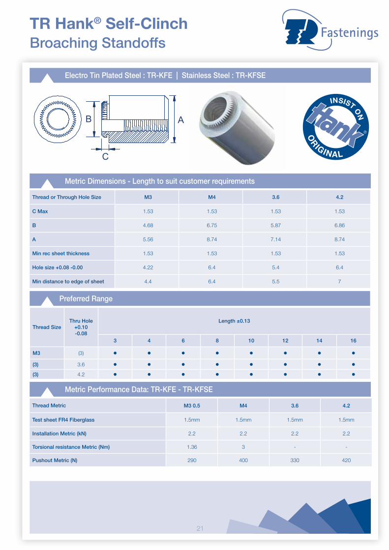
Electro Tin Plated Steel : TR-KFE | Stainless Steel : TR-KFSE
Metric Dimensions - Length to suit customer requirements
Thread or Through Hole Size M3 M4 3.6 4.2
C Max 1.53 1.53 1.53 1.53
B 4.68 6.75 5.87 6.86
A 5.56 8.74 7.14 8.74
Min rec sheet thickness 1.53 1.53 1.53 1.53
Hole size +0.08 -0.00 4.22 6.4 5.4 6.4
Min distance to edge of sheet 4.4 6.4 5.5 7
TR Hank® Self-Clinch Broaching Standoffs
Metric Performance Data: TR-KFE - TR-KFSE
AB
C
Thread Metric M3 0.5 M4 3.6 4.2
Test sheet FR4 Fiberglass 1.5mm 1.5mm 1.5mm 1.5mm
Installation Metric (kN) 2.2 2.2 2.2 2.2
Torsional resistance Metric (Nm) 1.36 3 - -
Pushout Metric (N) 290 400 330 420
Preferred Range
Thread SizeThru Hole
+0.10 -0.08
Length ±0.13
3 4 6 8 10 12 14 16
M3 (3) • • • • • • • •(3) 3.6 • • • • • • • •(3) 4.2 • • • • • • • •

22
Electro Tin Plated Steel : TR-KF2 | Stainless Steel : TR-KFS2
TR Hank® Self-Clinch Broaching Nuts
A
D
B
C
These tests have been conducted in laboratory conditions, these figures should therefore be used for guidance only.
All data is correct to the best of our knowledge, however TR cannot be held responsible for any errors or omissions.
Metric Dimensions
Thread M2 M2.5 M3 M3.5 M4 M5
C max 1.53 1.53 1.53 1.53 1.53 1.53
B ±0.08 4.19 4.68 4.68 5.88 6.86 7.37
A ±0.13 5.56 5.56 5.56 7 8.74 9.53
D ±0.13 1.5 1.5 1.5 1.6 2 3
Min rec sheet thickness 1.53 1.53 1.53 1.53 1.53 1.53
Hole size +0.08 -0.00 3.73 4.22 4.22 5.5 6.40 6.90
Min distance to edge of sheet
4.2 4.4 4.4 5.5 6.4 7.1
Metric Performance Data: TR-KF2 - TR-KFS2
Thread M2 M2.5 M3 M3.5 M4 M5
Test sheet FR4 Fiberglass(Thickness)
1.5mm 1.5mm 1.5mm 1.5mm 1.5mm
Installation (kN) 2.2 2.2 2.2 2.2 2.2
Torsional resistance (Nm) 1.36 1.36 2.06 3.75 4.55
Pushout (N) 200 200 210 335 355
23
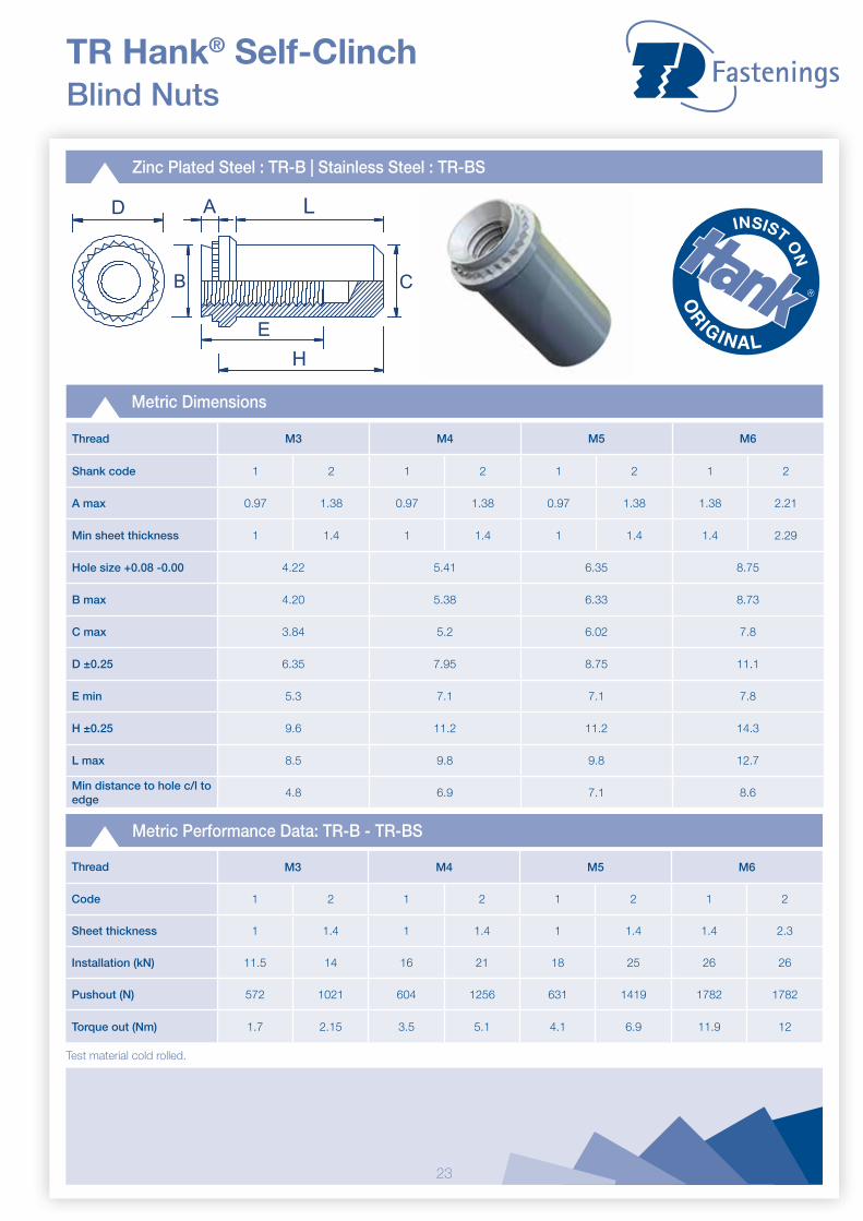
TR Hank® Self-Clinch Blind Nuts
Zinc Plated Steel : TR-B | Stainless Steel : TR-BS
B
A
H
C
E
LD
Metric Dimensions
Thread M3 M4 M5 M6
Shank code 1 2 1 2 1 2 1 2
A max 0.97 1.38 0.97 1.38 0.97 1.38 1.38 2.21
Min sheet thickness 1 1.4 1 1.4 1 1.4 1.4 2.29
Hole size +0.08 -0.00 4.22 5.41 6.35 8.75
B max 4.20 5.38 6.33 8.73
C max 3.84 5.2 6.02 7.8
D ±0.25 6.35 7.95 8.75 11.1
E min 5.3 7.1 7.1 7.8
H ±0.25 9.6 11.2 11.2 14.3
L max 8.5 9.8 9.8 12.7
Min distance to hole c/l to edge
4.8 6.9 7.1 8.6
Metric Performance Data: TR-B - TR-BS
Thread M3 M4 M5 M6
Code 1 2 1 2 1 2 1 2
Sheet thickness 1 1.4 1 1.4 1 1.4 1.4 2.3
Installation (kN) 11.5 14 16 21 18 25 26 26
Pushout (N) 572 1021 604 1256 631 1419 1782 1782
Torque out (Nm) 1.7 2.15 3.5 5.1 4.1 6.9 11.9 12
Test material cold rolled.

24
Zinc Plated Steel : TR-LAS / TR-AS | Stainless Steel : TR-LAC / TR-AC
TR Hank® Self-Clinch Floating Fasteners - Locking & Non-Locking
D
C
A
B
h
Metric Dimensions
Thread size M3 M4 M5 M6
Code 1 2 1 2 1 2 2
A max 0.97 1.38 0.97 1.38 0.97 1.38 1.38
Min sheet thickness 0.97 1.38 0.97 1.38 0.97 1.38 1.38
Hole size +0.08 7.37 9.35 10.31 13.08
B max 7.35 9.33 10.29 13.06
C max 7.37 9.28 10.29 12.96
D ±0.4 9.14 11.18 11.94 15.24
h max - TR-LAS & TR-LAC 4.83 5.34 6.86 7.88
j max - TR-AS & TR-AC 3.31 3.31 4.32 5.34
Min distance to hole C/L to edge
7.62 8.64 9.14 10.67
Metric Performance Data
Thread M3 M4 M5 M6
Code 1 2 1 2 1 2 2
Sheet thickness 1 1.6 1 1.6 1 1.6 1.6
Installation (kN)TR-LAS & TR-LAC 13.3 13.3 13.3 13.3 15.6 15.6 22.2
TR-AS & TR-AC 13.4 13.4 13.4 13.4 15.7 15.7 22.3
Test material - Cold rolled steel
Pushout (N) 1341 1340 1338 1784 1789 2009 2226
Torque out (Nm) - TR-LAS & TR-LAC
9.7 17 17.1 22.8 16.9 22.9 36.9
Torque out (Nm) - TR-AS & TR-AC
9.8 17.2 17 22.9 17 22.9 36.9
D
C
A
B
J

25
TR Hank® Self-Clinch Panel Fasteners
Stainless Steel : TR-PFC2 | Steel : TR-PFS2
BA
L
D
E
C
L1
Metric Dimensions
Thread size M3 M4 M5 M6
Screw length code 40 62 50 72 94 50 72 94 60 82 04
A max 1.53 1.53 1.53 1.53
B max 6.71 7.9 8.72 10.47
C +/-0.4 6.4 9.5 7.9 11.1 14.3 7.9 11.1 14.3 9.5 12.7 15.9
D +/-0.13 1.83 2.08 2.08 2.46
E +/-0.25 7.92 9.53 10.31 11.89
L nom 13.72 17.53 17.53 22.35
L1 max 9.14 11.43 11.47 14.73
Min sheet thickness 1.53 1.53 1.53 1.53
Hole size in sheet +0.08 6.73 7.90 8.74 10.49
Screw protrusion before installation +/-0.64
0 3.2 0 3.2 6.4 0 3.2 6.4 0 3.2 6.4
Min distance to hole C/L from edge
6.35 7.87 8.63 9.65
Metric Performance Data: TR-PFC2 - TR-PFS2
Test sheet M3 M4 M5 M6
Installation (kN) Aluminium 10.8 13 13.4 15.6
Steel 13.4 17 17.9 22.3
Pushout (N) Aluminium 1070 1335 1780 1780
Steel 1335 1780 2230 2670
26
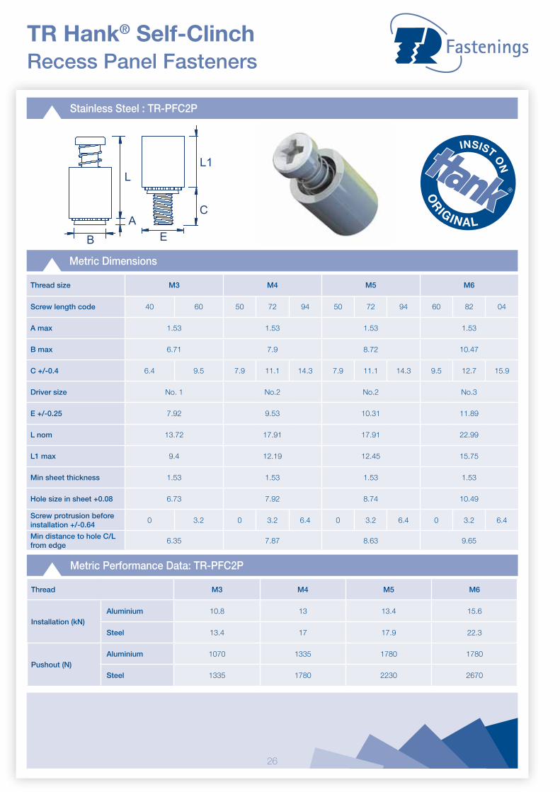
TR Hank® Self-Clinch Recess Panel Fasteners
Stainless Steel : TR-PFC2P
B
L
AE
L1
C
Metric Dimensions
Thread size M3 M4 M5 M6
Screw length code 40 60 50 72 94 50 72 94 60 82 04
A max 1.53 1.53 1.53 1.53
B max 6.71 7.9 8.72 10.47
C +/-0.4 6.4 9.5 7.9 11.1 14.3 7.9 11.1 14.3 9.5 12.7 15.9
Driver size No. 1 No.2 No.2 No.3
E +/-0.25 7.92 9.53 10.31 11.89
L nom 13.72 17.91 17.91 22.99
L1 max 9.4 12.19 12.45 15.75
Min sheet thickness 1.53 1.53 1.53 1.53
Hole size in sheet +0.08 6.73 7.92 8.74 10.49
Screw protrusion before installation +/-0.64
0 3.2 0 3.2 6.4 0 3.2 6.4 0 3.2 6.4
Min distance to hole C/L from edge
6.35 7.87 8.63 9.65
Metric Performance Data: TR-PFC2P
Thread M3 M4 M5 M6
Installation (kN) Aluminium 10.8 13 13.4 15.6
Steel 13.4 17 17.9 22.3
Pushout (N) Aluminium 1070 1335 1780 1780
Steel 1335 1780 2230 2670
27
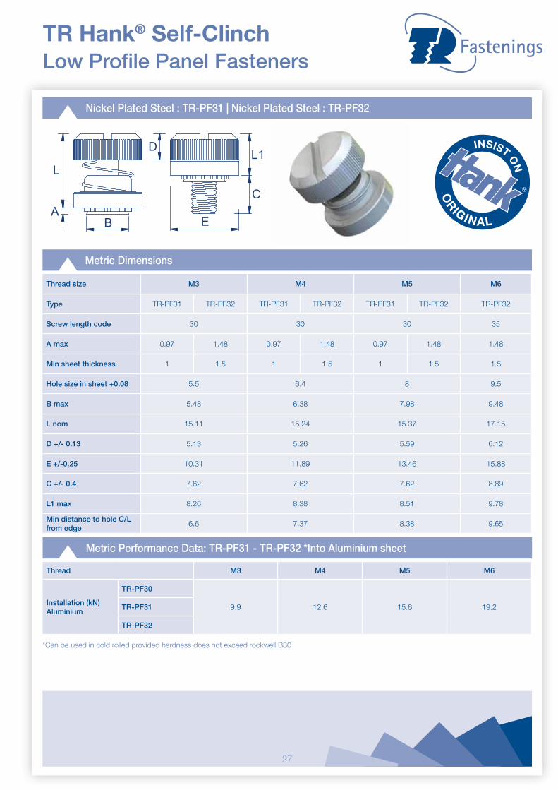
TR Hank® Self-ClinchLow Profile Panel Fasteners
Nickel Plated Steel : TR-PF31 | Nickel Plated Steel : TR-PF32
BA
L
D
E
C
L1
Metric Dimensions
Thread size M3 M4 M5 M6
Type TR-PF31 TR-PF32 TR-PF31 TR-PF32 TR-PF31 TR-PF32 TR-PF32
Screw length code 30 30 30 35
A max 0.97 1.48 0.97 1.48 0.97 1.48 1.48
Min sheet thickness 1 1.5 1 1.5 1 1.5 1.5
Hole size in sheet +0.08 5.5 6.4 8 9.5
B max 5.48 6.38 7.98 9.48
L nom 15.11 15.24 15.37 17.15
D +/- 0.13 5.13 5.26 5.59 6.12
E +/-0.25 10.31 11.89 13.46 15.88
C +/- 0.4 7.62 7.62 7.62 8.89
L1 max 8.26 8.38 8.51 9.78
Min distance to hole C/L from edge
6.6 7.37 8.38 9.65
Metric Performance Data: TR-PF31 - TR-PF32 *Into Aluminium sheet
Thread M3 M4 M5 M6
Installation (kN)Aluminium
TR-PF30
9.9 12.6 15.6 19.2TR-PF31
TR-PF32
*Can be used in cold rolled provided hardness does not exceed rockwell B30

28
TR Hank® Self-Clinch Installation Guides
Flush Head Studs (TR-FH | TR-FHS | TR-FHA)
Tooling for sheet thickness up to 1.50 for M3 - M5 and up to 2.40 for M6
Tooling for sheet thickness above 1.50 for M3 - M5 and above 2.40 for M6 and M8
Thread & Pitch M2.5 M3 M3.5 M4 M5 M6
D mm +0.08 2.53 3.03 3.53 4.03 5.03 6.03
B mm +0.1 3.1 3.6 4.1 4.6 5.6 6.6
Thread & Pitch M2.5 M3 M3.5 M4 M5 M6 M8
D mm +0.08 2.53 3.03 3.53 4.03 5.03 6.03 8.03
Installation
• Punch or drill the mounting hole. The Hank-Clinch stud data sheet shows the correct hole sizes. Do not deburr the hole or perform any other secondary operations.
• Place stud into mounting hole - ideally through the punch side. • Apply squeezing force, ensuring that the punch and anvil surfaces are parallel, until the head of the stud is flush
with the face of the sheet.
Flat Punch
Sheet
B45º
DL+
3.2mm Anvil
Sheet
D
L+3.2mm Anvil
Flat Punch
Flush Head Studs for Stainless Steel (TR-FH4)
Thread Size M3 M4 M5
C mm +0.08 3.05 4.04 5.08
D mm +/-0.05 3.81 4.95 6.15
E mm +/-0.05 4.57 5.82 7.16
R mm +/-0.025 0.25 0.25 0.25
T1 max. 0.08 0.08 0.08
T2 max. 0.13 0.13 0.13
Installation
• Punch the mounting hole. The Hank-Clinch stud data sheet shows the correct hole sizes. Do not deburr the hole or perform any other secondary operations.
• Place stud into mounting hole - ideally through the punch side. • Apply squeezing force, ensuring that the punch and anvil surfaces are parallel, until the head of the stud is flush
with the face of the sheet.
Note: An anvil with a raised ring is required to ensure correct installation.
Punch
Anvil
Recommended installation anvil
D95°Nom
E
C45˚Nom
RT1
T2
L+3.18mm
Flush Head Pins (TR-TP | TR-TPS)
Type A Pin Dia. 3 mm 4 mm 5 mm 6 mm
Max Sheet Thickness 1.7 mm 1.7 mm 1.8 mm 1.9 mm
A mm +/- 0.05 3.88 4.88 5.89 6.89
C mm +/- 0.05 3.11 4.11 5.13 6.12
Installation
• Punch or drill the mounting hole. The Hank-Clinch pin data sheet shows the correct hole sizes. Do not deburr the hole or perform any other secondary operations.
• Place pin into mounting hole - ideally through the punch side. • Apply squeezing force, ensuring that the punch and anvil surfaces are parallel, until the head of the pin is flush with
the face of the sheet.
Type B Pin Dia. 3 mm 4 mm 5 mm 6 mm
Min Sheet Thickness 1.7 mm 1.7 mm 1.8 mm 1.9 mm
A mm +/- 0.05 N/A N/A N/A N/A
C mm +/- 0.05 3.11 4.11 5.13 6.12
Sheet
Punch
Anvil
60º
L+.125/"3.18mm
AC
Type A
L+.125/"3.18mm
CType B
29
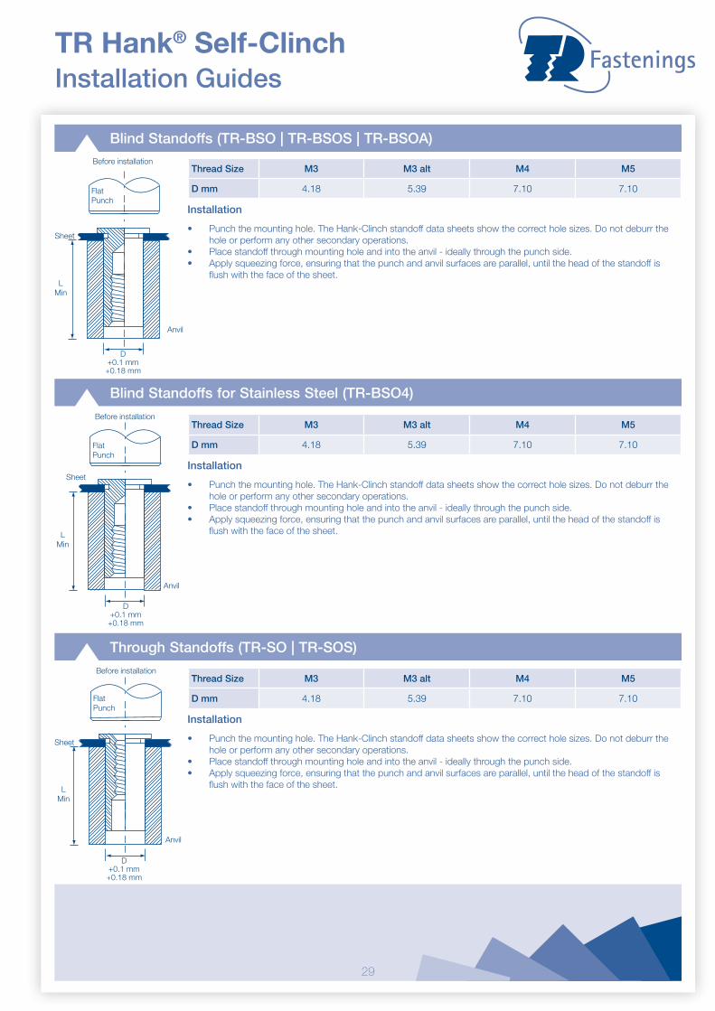
TR Hank® Self-ClinchInstallation Guides
Blind Standoffs (TR-BSO | TR-BSOS | TR-BSOA)
Thread Size M3 M3 alt M4 M5
D mm 4.18 5.39 7.10 7.10
Installation
• Punch the mounting hole. The Hank-Clinch standoff data sheets show the correct hole sizes. Do not deburr the hole or perform any other secondary operations.
• Place standoff through mounting hole and into the anvil - ideally through the punch side. • Apply squeezing force, ensuring that the punch and anvil surfaces are parallel, until the head of the standoff is
flush with the face of the sheet.
Before installation
FlatPunch
Anvil
LMin
D+0.1 mm
+0.18 mm
Sheet
Blind Standoffs for Stainless Steel (TR-BSO4)
Thread Size M3 M3 alt M4 M5
D mm 4.18 5.39 7.10 7.10
Installation
• Punch the mounting hole. The Hank-Clinch standoff data sheets show the correct hole sizes. Do not deburr the hole or perform any other secondary operations.
• Place standoff through mounting hole and into the anvil - ideally through the punch side. • Apply squeezing force, ensuring that the punch and anvil surfaces are parallel, until the head of the standoff is
flush with the face of the sheet.
Before installation
Anvil
LMin
D+0.1 mm
+0.18 mm
FlatPunch
Sheet
Through Standoffs (TR-SO | TR-SOS)
Thread Size M3 M3 alt M4 M5
D mm 4.18 5.39 7.10 7.10
Installation
• Punch the mounting hole. The Hank-Clinch standoff data sheets show the correct hole sizes. Do not deburr the hole or perform any other secondary operations.
• Place standoff through mounting hole and into the anvil - ideally through the punch side. • Apply squeezing force, ensuring that the punch and anvil surfaces are parallel, until the head of the standoff is
flush with the face of the sheet.
Before installation
FlatPunch
Anvil
LMin
D+0.1 mm
+0.18 mm
Sheet
30
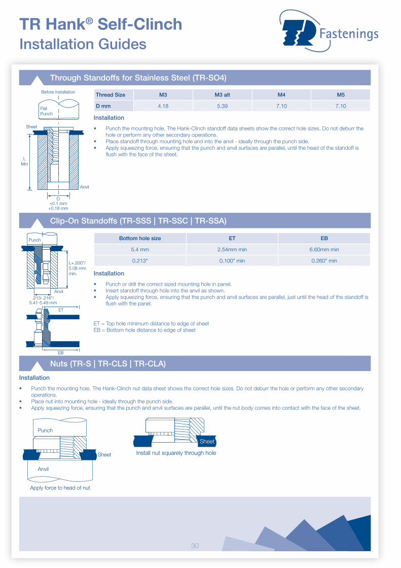
TR Hank® Self-Clinch Installation Guides
Through Standoffs for Stainless Steel (TR-SO4)
Thread Size M3 M3 alt M4 M5
D mm 4.18 5.39 7.10 7.10
Installation
• Punch the mounting hole. The Hank-Clinch standoff data sheets show the correct hole sizes. Do not deburr the hole or perform any other secondary operations.
• Place standoff through mounting hole and into the anvil - ideally through the punch side. • Apply squeezing force, ensuring that the punch and anvil surfaces are parallel, until the head of the standoff is
flush with the face of the sheet.
Before installation
FlatPunch
Anvil
LMin
D+0.1 mm
+0.18 mm
Sheet
Clip-On Standoffs (TR-SSS | TR-SSC | TR-SSA)
Bottom hole size ET EB
5.4 mm 2.54mm min 6.60mm min
0.213" 0.100" min 0.260" min
Installation
• Punch or drill the correct sized mounting hole in panel. • Insert standoff through hole into the anvil as shown.• Apply squeezing force, ensuring that the punch and anvil surfaces are parallel, just until the head of the standoff is
flush with the panel.
ET = Top hole minimum distance to edge of sheetEB = Bottom hole distance to edge of sheet
Punch
Anvil
L+.200"/ 5.08 mm min.
.213-.216"/ 5.41-5.49 mm
ET
EB
Nuts (TR-S | TR-CLS | TR-CLA)
Installation
• Punch the mounting hole. The Hank-Clinch nut data sheet shows the correct hole sizes. Do not deburr the hole or perform any other secondary operations.
• Place nut into mounting hole - ideally through the punch side. • Apply squeezing force, ensuring that the punch and anvil surfaces are parallel, until the nut body comes into contact with the face of the sheet.
Install nut squarely through hole
Sheet
Punch
Anvil
Apply force to head of nut
Sheet
31
TR Hank® Self-ClinchInstallation Guides
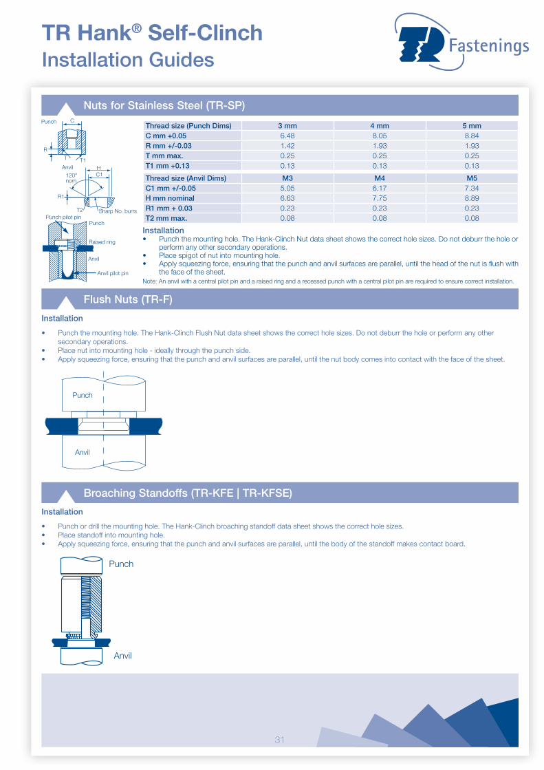
Nuts for Stainless Steel (TR-SP)
Thread size (Punch Dims) 3 mm 4 mm 5 mmC mm +0.05 6.48 8.05 8.84R mm +/-0.03 1.42 1.93 1.93T mm max. 0.25 0.25 0.25T1 mm +0.13 0.13 0.13 0.13
Installation• Punch the mounting hole. The Hank-Clinch Nut data sheet shows the correct hole sizes. Do not deburr the hole or
perform any other secondary operations. • Place spigot of nut into mounting hole. • Apply squeezing force, ensuring that the punch and anvil surfaces are parallel, until the head of the nut is flush with
the face of the sheet.Note: An anvil with a central pilot pin and a raised ring and a recessed punch with a central pilot pin are required to ensure correct installation.
Thread size (Anvil Dims) M3 M4 M5C1 mm +/-0.05 5.05 6.17 7.34H mm nominal 6.63 7.75 8.89R1 mm + 0.03 0.23 0.23 0.23T2 mm max. 0.08 0.08 0.08Punch pilot pin
Punch
Anvil
Anvil pilot pin
Raised ring
Sharp No. burrs
Anvil HC1120°
nom
R1
T2
C
T T1
R
Punch
Flush Nuts (TR-F)
Installation
• Punch the mounting hole. The Hank-Clinch Flush Nut data sheet shows the correct hole sizes. Do not deburr the hole or perform any other secondary operations.
• Place nut into mounting hole - ideally through the punch side. • Apply squeezing force, ensuring that the punch and anvil surfaces are parallel, until the nut body comes into contact with the face of the sheet.
Punch
Anvil
Broaching Standoffs (TR-KFE | TR-KFSE)
Installation
• Punch or drill the mounting hole. The Hank-Clinch broaching standoff data sheet shows the correct hole sizes. • Place standoff into mounting hole. • Apply squeezing force, ensuring that the punch and anvil surfaces are parallel, until the body of the standoff makes contact board.
Punch
Anvil

32
Punch
Anvil
TR Hank® Self-Clinch Installation Guides
Broaching Nuts (TR-KF2 | TR-KFS2)
Installation
• Punch or drill the mounting hole. The Hank-Clinch broaching nut data sheet shows the correct hole sizes. • Place nut into mounting hole. • Apply squeezing force, ensuring that the punch and anvil surfaces are parallel, until the body of the nut makes contact board.
Blind Nuts (TR-B | TR-BS)
Thread Size M3 M4 M5 M6
B mm 3.84 5.20 6.02 7.80
L Dim 8.5 9.8 9.8 12.7
Installation
• Punch the mounting hole. The Hank-Clinch blind nut data sheet shows the correct hole sizes. Do not deburr the hole or perform any other secondary operations.
• Place nut through mounting hole and into the anvil - ideally through the punch side. • Apply squeezing force, ensuring that the punch and anvil surfaces are parallel, until the flange of the nut makes
contact with the face of the sheet.
FlatPunch
Anvil
B+0.15mm+0.08mm
0.25mm x 45˚ nom. Chamfer
L+1.5 mmmin.
Floating Fasteners: Non-Locking | Locking (TR-AS | TR-AC | TR-LAS | TR-LAC)
Thread M3 M4 M5 M6
D mm 7.4 9.3 10.3 13.8
Installation - Non-Locking: TR-AS | TR-AC
• Punch the mounting hole. The Hank-Clinch Floating Nut data sheet shows the correct hole sizes. Do not deburr the hole or perform any other secondary operations.
• Place nut into mounting hole - ideally through the punch side. • Apply squeezing force, ensuring that the punch and anvil surfaces are parallel, until the flange head of the nut is
flush with the face of the sheet.
Installation - Locking: TR-LAS | TR-LAC
• Punch or drill the mounting hole. The Hank-Clinch floating fastener data sheets show the correct hole sizes. Do not deburr the hole or perform any other secondary operations.
• Place stud into mounting hole - ideally through the punch side. • Apply squeezing force, ensuring that the punch and anvil surfaces are parallel, until the flange head of the nut is
flush with the face of the sheet.
Punch
Anvil
.25"/8mm min.
D+.005"/+0.13mm +.010"/+0.25mm
Punch
Anvil
.25"/8mm min.
D+.005"/+0.13mm+.010"/+0.25mm

33
TR Hank® Self-ClinchInstallation Guides
Panel Fasteners (TR-PFC2 | TR-PFS2)
Thread Size M3 M4 M5 M6
A mm +/- 0.05 8.76 11.05 11.05 14.35
C Dim +/- 0.05 8.2 9.8 10.69 12.29
Installation
• Punch or drill the mounting hole. The Hank-Clinch panel fastener data sheet shows the correct hole sizes. Do not deburr the hole or perform any other secondary operations.
• Place fastener into anvil recess then place sheet over the fastener spigot. • Apply squeezing force, ensuring that the punch and anvil surfaces are parallel, until the retainer shoulder makes
contact with the face of the sheet.
Punch
Anvil
Thread Dia. +2mm
G min.
A
C
Recess Panel Fasteners (TR-PFC2P)
Thread Size M3 M4 M5 M6
A mm +/- 0.05 8.76 11.05 11.05 14.35
C Dim +/- 0.05 8.2 9.8 10.69 12.29
Installation
• Punch or drill the mounting hole. The Hank-Clinch panel fastener data sheet shows the correct hole sizes. Do not deburr the hole or perform any other secondary operations.
• Place fastener into anvil recess then place sheet over the fastener spigot. • Apply squeezing force, ensuring that the punch and anvil surfaces are parallel, until the retainer shoulder makes
contact with the face of the sheet.
Punch
Anvil
Thread Dia. +2mm
G min.
A
C
Low Profile Panel Fasteners (TR-PF31 | TR-PF32)
Thread Size M3 M4 M5 M6
A mm +/- 0.05 7.49 7.87 7.87 9.27
C Dim +/- 0.05 10.69 12.29 13.87 16.26
Installation
• Punch the mounting hole. The Hank-Clinch panel fastener data sheet shows the correct hole sizes. Do not deburr the hole or perform any other secondary operations.
• Place fastener into anvil recess then place sheet over the fastener spigot. • Apply squeezing force, ensuring that the punch and anvil surfaces are parallel, until the retainer shoulder makes
contact with the face of the sheet.
Punch
Anvil
Thread Dia. +.080"/+2mm
G min.
A
C

TR FASTENINGSContact Us
[email protected]@[email protected]
UKt: 08454 811 800 f: 0870 458 7851e-mail: [email protected]
Irelandt: +353 (0)22 22301 f: +353 (0)22 22056e-mail: [email protected]
Netherlandst: +31 (0)541 511515 f: +31 (0)541 517134e-mail: [email protected]
Norwayt: +47 67 06 70 00 f: +47 67 06 70 10e-mail: [email protected]
Swedent: +46 (0)8 578 44 900 f: +46 (0)8 578 44 950e-mail: [email protected]
Hungaryt: +36 24 516 972 f: +36 24 516 961e-mail: [email protected]
Polandt: +48 (22) 402 36 14 f: +48 (22) 402 36 24e-mail: [email protected]
Singaporet: +65 6759 6033 f: +65 6759 6022e-mail: [email protected]
Chinat: +86 21 5032 5696 f: +86 21 5032 5775e-mail: [email protected]
Taiwant: +866 7 552 5577 f: +886 7 552 7033e-mail: [email protected]
Malaysiat: +604 508 3931/2 f: +604 508 3942e-mail: [email protected]
Indiat: +91 967707 1807 m: +65 9684 1763e-mail: [email protected]
Thailandt: +66 38491 430 f: +66 38491 430e-mail: [email protected]
USAt: +1 (800) 280 2181 f: +1 (281) 807 0620e-mail: [email protected]
Master Distributor Details