tr 102 839 - v1.1.1 - reconfigurable radio systems (rrs
TRANSCRIPT

ETSI TR 102 839 V1.1.1 (2011-04)
Technical Report
Reconfigurable Radio Systems (RRS);Multiradio Interface for Software Defined Radio (SDR)
Mobile Device Architecture and Services

ETSI
ETSI TR 102 839 V1.1.1 (2011-04) 2
Reference DTR/RRS-02004
Keywords architecture, radio
ETSI
650 Route des Lucioles F-06921 Sophia Antipolis Cedex - FRANCE
Tel.: +33 4 92 94 42 00 Fax: +33 4 93 65 47 16
Siret N° 348 623 562 00017 - NAF 742 C
Association à but non lucratif enregistrée à la Sous-Préfecture de Grasse (06) N° 7803/88
Important notice
Individual copies of the present document can be downloaded from: http://www.etsi.org
The present document may be made available in more than one electronic version or in print. In any case of existing or perceived difference in contents between such versions, the reference version is the Portable Document Format (PDF).
In case of dispute, the reference shall be the printing on ETSI printers of the PDF version kept on a specific network drive within ETSI Secretariat.
Users of the present document should be aware that the document may be subject to revision or change of status. Information on the current status of this and other ETSI documents is available at
http://portal.etsi.org/tb/status/status.asp
If you find errors in the present document, please send your comment to one of the following services: http://portal.etsi.org/chaircor/ETSI_support.asp
Copyright Notification
No part may be reproduced except as authorized by written permission. The copyright and the foregoing restriction extend to reproduction in all media.
© European Telecommunications Standards Institute 2011.
All rights reserved.
DECTTM, PLUGTESTSTM, UMTSTM, TIPHONTM, the TIPHON logo and the ETSI logo are Trade Marks of ETSI registered for the benefit of its Members.
3GPPTM is a Trade Mark of ETSI registered for the benefit of its Members and of the 3GPP Organizational Partners. LTE™ is a Trade Mark of ETSI currently being registered
for the benefit of its Members and of the 3GPP Organizational Partners. GSM® and the GSM logo are Trade Marks registered and owned by the GSM Association.

ETSI
ETSI TR 102 839 V1.1.1 (2011-04) 3
Contents
Intellectual Property Rights ................................................................................................................................ 5
Foreword ............................................................................................................................................................. 5
1 Scope ........................................................................................................................................................ 6
2 References ................................................................................................................................................ 6
2.1 Normative references ......................................................................................................................................... 6
2.2 Informative references ........................................................................................................................................ 6
3 Definitions and abbreviations ................................................................................................................... 7
3.1 Definitions .......................................................................................................................................................... 7
3.2 Abbreviations ..................................................................................................................................................... 7
4 Use scenarios for SDR based mobile devices .......................................................................................... 8
4.1 Mobile device functionality ................................................................................................................................ 9
4.1.1 Power on ....................................................................................................................................................... 9
4.1.2 Context provisioning..................................................................................................................................... 9
4.1.3 Link selection ................................................................................................................................................ 9
4.1.4 Sensing request and delivery of sensing results ............................................................................................ 9
4.1.5 Change of remote (base station or mobile device) configuration ................................................................. 9
4.1.6 Installing new software components for support of novel standards .......................................................... 10
4.1.7 Addition of new functionality on top of SDR subsystem ........................................................................... 10
4.2 Architecture implications ................................................................................................................................. 10
5 Mobile device SDR operating environment ........................................................................................... 11
5.1 Radio computer concept ................................................................................................................................... 11
5.2 SDR value network .......................................................................................................................................... 13
5.3 Radio computer capabilities ............................................................................................................................. 14
5.4 Radio computer deployment scenarios ............................................................................................................. 14
5.4.1 Scenario 1: Radio access technologies are legacy implementations ........................................................... 14
5.4.2 Scenario 2: Radio applications use pre-defined fixed resources ................................................................. 15
5.4.3 Scenario 3: Radio applications have fixed resource requirements .............................................................. 15
5.4.4 Scenario 4: Radio applications have dynamic resource requirements ........................................................ 15
5.4.5 Scenario 5: Radio applications come from third-party vendors .................................................................. 15
6 SDR mobile device reference architecture overview ............................................................................. 15
6.1 SDR control framework ................................................................................................................................... 16
6.2 Unified radio applications (URA) .................................................................................................................... 17
6.3 Key interfaces ................................................................................................................................................... 18
6.3.1 Multiradio interface (MURI) ...................................................................................................................... 18
6.3.2 Unified Radio Application Interface (URAI) ............................................................................................. 18
7 Multiradio interface design goals ........................................................................................................... 19
8 Multiradio interface concept definitions ................................................................................................ 19
9 Information model .................................................................................................................................. 21
9.1 Radio application package ................................................................................................................................ 22
9.1.1 Capabilities ................................................................................................................................................. 22
9.1.2 Executable components .............................................................................................................................. 22
9.2 Radio application instances .............................................................................................................................. 23
9.3 Measurement information from radio applications .......................................................................................... 24
9.4 Connectivity elements ...................................................................................................................................... 25
10 Service description ................................................................................................................................. 25
10.1 Administrative services .................................................................................................................................... 26
10.1.1 Install radio application .............................................................................................................................. 27
10.1.2 Uninstall radio application .......................................................................................................................... 27
10.1.3 Create radio application instance ................................................................................................................ 28
10.1.4 Delete radio application instance ................................................................................................................ 28

ETSI
ETSI TR 102 839 V1.1.1 (2011-04) 4
10.1.5 Get radio application parameters ................................................................................................................ 29
10.1.6 Set radio application parameters ................................................................................................................. 30
10.1.7 List radio applications ................................................................................................................................. 30
10.2 Access control services .................................................................................................................................... 31
10.2.1 Activate a radio application instance .......................................................................................................... 31
10.2.2 Deactivate a radio application instance ....................................................................................................... 31
10.2.3 Start radio environment measurements ....................................................................................................... 32
10.2.4 Stop radio environment measurements ....................................................................................................... 33
10.2.5 Radio environment measurement indication ............................................................................................... 33
10.2.6 Create association with peer, mobile device originated .............................................................................. 34
10.2.7 Create association with peer, peer device originated .................................................................................. 35
10.2.8 Terminate association, mobile device originated ........................................................................................ 36
10.2.9 Terminate association, peer device originated ............................................................................................ 36
10.2.10 Create data flow into association, mobile device originated ....................................................................... 37
10.2.11 Create data flow into association, peer device originated ........................................................................... 38
10.2.12 Terminate data flow, mobile device originated........................................................................................... 39
10.2.13 Terminate data flow, peer device originated ............................................................................................... 39
10.2.14 Move data flow from association into another ............................................................................................ 40
10.3 Data flow services ............................................................................................................................................ 40
10.3.1 Send user data ............................................................................................................................................. 40
10.3.2 Receive user data ........................................................................................................................................ 41
History .............................................................................................................................................................. 42

ETSI
ETSI TR 102 839 V1.1.1 (2011-04) 5
Intellectual Property Rights IPRs essential or potentially essential to the present document may have been declared to ETSI. The information pertaining to these essential IPRs, if any, is publicly available for ETSI members and non-members, and can be found in ETSI SR 000 314: "Intellectual Property Rights (IPRs); Essential, or potentially Essential, IPRs notified to ETSI in respect of ETSI standards", which is available from the ETSI Secretariat. Latest updates are available on the ETSI Web server (http://webapp.etsi.org/IPR/home.asp).
Pursuant to the ETSI IPR Policy, no investigation, including IPR searches, has been carried out by ETSI. No guarantee can be given as to the existence of other IPRs not referenced in ETSI SR 000 314 (or the updates on the ETSI Web server) which are, or may be, or may become, essential to the present document.
Foreword This Technical Report (TR) has been produced by ETSI Technical Committee Reconfigurable Radio Systems (RRS).

ETSI
ETSI TR 102 839 V1.1.1 (2011-04) 6
1 Scope The present document is a study item that can be used in the normative process within ETSI TC RRS, when defining normative system requirements, architecture, and interfaces for Mobile Device (MD) Software Defined Radio (SDR).
The TR 102 680 [i.1] presents a reference architecture for Software Defined Radio (SDR) mobile devices from a radio computer viewpoint. Such a device can run radio applications on shared platform resources, and install new ones even during run-time, much like a personal computer with regular computer programs. The reference architecture details the internals of a possible mobile device SDR subsystem, but is not meant to be a normative architecture. Instead, it identifies various key interfaces that may be generalized in order for the multiradio computer vision to be realized. These interfaces may be normative.
SDR can be on one hand considered as an implementation technology that replaces legacy ASICs when suitable cost and power tradeoffs can be found; this track is not in the scope of ETSI TC RRS. On the other hand, SDR can be considered as an enabling technology for Cognitive Radio (CR) systems. It is in the scope of ETSI TC RRS to define the responsibilities of various subsystems in a complete CR system. The TR 103 062 [i.2] lists high level use scenarios for SDR based mobile devices, to be used in this process.
The two approaches meet at the interface to the SDR subsystem. This is called the Multiradio Interface (MURI) in the reference architecture. The purpose of this technical report is to outline the functionality at this interface, both from SDR technology and CR system perspectives. The use scenarios are analyzed first, in order to partition the responsibilities between the SDR subsystem and the CR entities on top of it. Then the SDR subsystem is taken a deeper look, based on TR 102 680 [i.1] and technology deployment scenarios. Finally the MURI functionality is sketched from these basis.
2 References References are either specific (identified by date of publication and/or edition number or version number) or non-specific. For specific references,only the cited version applies. For non-specific references, the latest version of the referenced document (including any amendments) applies.
Referenced documents which are not found to be publicly available in the expected location might be found at http://docbox.etsi.org/Reference.
NOTE: While any hyperlinks included in this clause were valid at the time of publication ETSI cannot guarantee their long term validity.
2.1 Normative references The following referenced documents are necessary for the application of the present document.
Not applicable.
2.2 Informative references The following referenced documents are not necessary for the application of the present document but they assist the user with regard to a particular subject area.
[i.1] ETSI TR 102 680: "Reconfigurable Radio Systems (RRS); SDR Reference Architecture for Mobile Device".
[i.2] ETSI TR 103 062: "Reconfigurable Radio Systems (RRS) Use Cases and Scenarios for Software Defined Radio (SDR) Reference Architecture for Mobile Device".
[i.3] IEEE 802.11: "Standard for Information Technology-Telecommunications and Information Exchange Between Systems-Local and Metropolitan Area Networks-Specific Requirements - Part 11: Wireless LAN Medium Access Control (MAC) and Physical Layer (PHY) Specifications".

ETSI
ETSI TR 102 839 V1.1.1 (2011-04) 7
3 Definitions and abbreviations
3.1 Definitions For the purposes of the present document, the following terms and definitions apply:
mobile device: personal communication device (e.g. mobile phone, PDA, laptop PC, etc.) capable of communicating either locally (e.g. Bluetooth), through a network (e.g. GSM) or both by using one or more radio technologies
radio application: software application executing in a software defined multiradio equipment
NOTE: Radio application is typically designed to use certain radio frequency band(s) and it includes agreed schemes for multiple access, modulation, channel and data coding as well as control protocols for all radio layers needed to maintain user data links between adjacent radio equipments, which run the same radio application.
radio equipment: equipment using radio technology
radio system: system which consists of a number of radio equipments using at least one common radio technology
software defined multiradio: device or technology where multiple radio technologies can coexist and share their wireless transmission and/or reception capabilities, including but not limited to regulated parameters, by operating them under a common software system
NOTE 1: Examples of the regulated parameters are frequency range, modulation type, and output power.
NOTE 2: Common software system represents radio operating system functions.
NOTE 3: This definition does not restrict the way software is used to set and/or change the parameters. In one example, this can be done by the algorithm of the already running software. In another example, software downloading may be required.
software defined radio: radio in which the RF operating parameters including, but not limited to, frequency range, modulation type, or output power can be set or altered by software, and/or the technique by which this is achieved
NOTE 1: Excludes changes to operating parameters which occur during the normal pre-installed and predetermined operation of a radio according to a systen specification or standard.
NOTE 2: SDR is an implementation technique applicable to many radio technologies and standards.
NOTE 3: SDR techniques are applicable to both transmitters and receivers.
software defined radio equipment: radio equipment supporting SDR technology
3.2 Abbreviations For the purposes of the present document, the following abbreviations apply:
ASIC Application Specific Integrated Circuit BB BaseBand CF Cognitive Functionality CM Configuration Manager CR Cognitive Radio DVB: Digital Video Broadcasting EMC Electro-Magnetic Compatibility FC Flow Controller FEM: Front End Module FM: Frequency Modulation GGSN Gateway GPRS Support Node GPRS General Packet Radio System GPS: Global Positioning System GSM Global System for Mobile communications

ETSI
ETSI TR 102 839 V1.1.1 (2011-04) 8
HSxPA: High Speed Packet Access HW HardWare IP Intellectual Property
NOTE: As in semiconductor IP.
IP Internet Protocol
NOTE: As in TCP/IP.
LTE Long Term Evolution MAC: Medium Access Control MD Mobile Device MRC MultiRadio Controller MURI MUltiRadio Interface
NOTE: Renamed from "Multiradio Access Interface" in [i.1].
PDA Personal Digital Assistant PDP Packet Data Protocol RAT Radio Access Technology RCM Radio Connection Manager RF Radio Frequency RFFI Reconfigurable RF Interface RM Resource Manager RPI Radio Programming Interface RRS Reconfigurable Radio System SDR Software Defined Radio SMS Short Message Service SSID: Service Set Identifier SW: Software TCP Transport Control Protocol TRx: Transceiver UMTS: Universal Mobile Telecommunications System URA Unified Radio Application URAI Unified Radio Application Interface WCDMA Wideband Code Division Multiple Access WLAN Wireless Local Area Network
4 Use scenarios for SDR based mobile devices High level use scenarios for SDR based mobile devices have been collected in [i.2]. These use cases are used to define system requirements for SDR mobile devices but not in the scope of the present document; the focus here is in drawing the mobile device SDR architecture and responsibilities for the architectural components. The high level use scenarios are:
• Terminal-centric configuration in a heterogeneous radio context. In this scenario, the mobile device is able to detect a heterogeneous wireless framework, consisting of cellular systems, wireless local area networks, wireless personal area networks, etc. Based on its configuration capabilities, it selects a single RAT or multiple RATs to camp on.
• Network driven terminal configuration in a heterogeneous radio context. Similarly as in the previous scenario, the mobile device operates on a heterogeneous wireless framework, but here a network decides which RATs the mobile device uses.
• Addition of new features, such as support for novel radio systems, to mobile devices. In this scenario, the mobile device is being updated with a new radio application, to support e.g. a novel radio standard.
• Provision of a new cognitive feature. In this scenario, the mobile device is being updated with a new cognitive feature, such as cross-technology spectrum measurement.

ETSI
ETSI TR 102 839 V1.1.1 (2011-04) 9
4.1 Mobile device functionality Each of the use scenarios is analyzed, and the functionality in the scenario description and the information flow diagrams is expanded from the mobile device perspective.
4.1.1 Power on
Applicable to all usage scenarios.
The mobile device activates suitable RATs for the scenario. Not all RATs may be needed in all scenarios so they may remain inactive. The RATs that are activated start operating as per their radio standard.
The RATs that are not needed may be later deactivated, so they stop consuming power and platform resources.
4.1.2 Context provisioning
Applicable to the terminal and network centric configuration of mobile device scenarios.
The mobile device uses one or more of the active RATs to receive context information from a network (Cognitive Pilot Channel) or by inter-mobile communication. For this the mobile device needs to detect the availability of the network or other suitable mobile devices.
NOTE: Context information within integrated framework (such as 3GPP GSM, UMTS, HSxPA, LTE, LTE-Advanced) is not in the scope of the present document and the information exchange is handled by the corresponding RAT without implications on the SDR architecture.
4.1.3 Link selection
Applicable to the terminal and network centric configuration of mobile device scenarios.
The mobile devices selects one or more of the active RATs in order to form a communication link with a network or other mobile devices. For this the mobile device needs either up-to-date context information or its own sensing results. The selection criteria may include both network centric control schemes as well as autonomous operation by the mobile device.
NOTE: Only the selection of links between distinct systems which are not within an integrated framework (such as 3GPP GSM, UMTS, HSxPA, LTE, LTE-Advanced) is in the scope of the present document. Link selection within such an integrated framework is handled by the corresponding RAT according to the relevant standards, without implications on the SDR architecture.
4.1.4 Sensing request and delivery of sensing results
Applicable to the terminal and network centric configuration of mobile device scenarios.
The mobile device receives from a network or other mobile devices a request to perform sensing. The mobile device may do the sensing, aggregate the results, and send them back to the requester. The sensing may include RAT specific operations (e.g. finding networks or other mobile devices using specific technologies), feature detection using generic spectrum sensors (e.g. location of specific technologies on certain frequencies), and general spectrum measurements (e.g. detected power levels on certain frequencies).
NOTE: The present document considers only the sensing across distinct technologies that are not designed within an integrated framework (such as 3GPP GSM, UMTS, HSxPA, LTE, LTE-Advanced). Sensing or measurements within such an integrated framework is handled by the corresponding RAT according to the relevant standards, without implications on the SDR architecture.

ETSI
ETSI TR 102 839 V1.1.1 (2011-04) 10
4.1.5 Change of remote (base station or mobile device) configuration
Applicable to the terminal and network centric configuration of mobile device scenarios.
The base station that the mobile device has a connection to changes its configuration and requires that the mobile device is also reconfigured. This may also happen with a local connection between two mobile devices. The base station provides corresponding reconfiguration information such as the newly used RAT, frequencies, etc., and the mobile device may the reconfigure itself in order to maintain the connection.
NOTE: Configuration changes within systems in an integrated framework (such as 3GPP GSM, UMTS, HSxPA, LTE, LTE-Advanced) are not in the scope of the present document. They are handled by the corresponding RATs autonomously according to the relevant standards, and do not have implications on the SDR architecture.
4.1.6 Installing new software components for support of novel standards
Applicable to the addition of new radio software scenario.
New software components to be used by the SDR subsystem are available for the update of the mobile device. These components may be delivered for example using an active RAT. The mobile device (e.g. the SDR subsystem) checks the sanity and compatibility of the new components and may install them to be taken into use. The software components may be new or updated radio applications for the support of novel standards, for instance.
The addition of new software components after the manufacture of a mobile device may have implications on regulatory framework concerning SDR equipment.
4.1.7 Addition of new functionality on top of SDR subsystem
Applicable to the provision of new cognitive features scenario.
New software components are available for the update of the mobile device. These components may be delivered for example using an active RAT. The mobile device checks the sanity and compatibility of the new components and may install them to be taken into use. The software components may be e.g. cognitive control functions for new CR functionality.
As the software components are not used by the SDR subsystem, this use scenario has no impact on the SDR architecture, apart from the delivery of the components using a wireless interface. From the complete mobile device point of view this is important, and should be handled on the higher layers.
4.2 Architecture implications The functionality outlined above may have the following implications on the mobile device and SDR architecture.
Many of the cross-technology cognitive features can be seen as non-SDR related functionality. For example, initial scanning of available communication partners, possible context information reception using any of the available RATs, and the selection of links are independent of the implementation of the underlying radios. Such intelligence can be built on top of the SDR subsystem.
Any functionality internal to a RAT (individual radio standard or e.g. integrated 3GPP framework) is not in the scope of the present document. Examples of such functionality are searching of beacons or control channels of access points or base stations, message exchange procedures for joining a found network, etc. However, for the cross-technology cognitive features to function, some information from the RATs may be provided. This can include found networks, receive signal strength of these networks, and details of the provided services, for instance. Even if the RATs are not fully configurable by software, providing such information to the layers above can be used to realize a variety of cognitive functionalities.
Finally, as the set of available (i.e. installed) RATs and the cognitive functions may change during the lifetime of the mobile device, the interface between these should be generic. This means, that commonalities between specific RATs are abstracted. Within the present document, these relate to administration functions (i.e. installation and removal of RATs), control (i.e. requests of sensing, establishing connections), and user plane data transfer.

ETSI
ETSI TR 102 839 V1.1.1 (2011-04) 11
Figure 1: SDR and Cognitive Functionality in reconfigurable radio equipment
Figure 1 shows an example of how the SDR and cognitive functionalities may be split within the reconfigurable radio equipment, in order to enable independent development of both sides.
5 Mobile device SDR operating environment This clause collects some of the main topics of [i.1], such as the radio computer concept, SDR value network, and the most relevant interfaces.
5.1 Radio computer concept SDR equipment will operate in the same kinds of networking environments as today's mobile phones, PDAs and laptops. Both licensed and unlicensed frequency bands will remain in use. SDR equipments will be used in user terminals in operators' networks as well as peer equipments in short range, personal and ad hoc networks. Radio and TV broadcasting stations and geopositioning satellites will also be used as distant communication peers of SDR equipments.
Besides existing radio technologies new radio technologies and frequency bands will become available to SDR equipments. Therefore the design of SDR equipment architecture will be prepared for new frequency bands and radio systems – among them especially the ones supporting introduction of cognitive radio systems. More flexible schemes to use available radio frequencies will also emerge by introduction of spectrum sensing techniques, distribution of cognitive control information and use of commonly agreed spectrum etiquettes. From the SDR equipment architecture point of view both network-centric control schemes and autonomously operating mobile devices are equally valid in such future spectrum utilization cases.
Instead of engineering radios as embedded systems on RFICs, special-purpose digital signal processors and ASIC accelerators, future software defined multi-radio equipment may be seen as a computer where individual radio applications are engineered as software entities to run on more general-purpose computing elements. Such a radio computer is capable to run multiple radios simultaneously and can change this set of radios by loading new radio application software even at run-time. All radio applications exhibit a common behaviour from the radio computer point of view.
In order to share the available computing, memory, communications and RF resources the radio computer has a radio operating system, just like desktop computers have their operating system. Such a radio operating system supports coexistence of multiple radios even if they are operating on same or adjacent frequency bands. Radio operating system also provides run-time reconfiguration by installing, loading and activating new radio applications.

ETSI
ETSI TR 102 839 V1.1.1 (2011-04) 12
Figure 2: Radio computer concept
This parallelism to desktop computing leads to architecting the functionalities of a multiradio equipment as three horizontal layers: physical radio computing platform, operating system and radio applications as shown in Figure 2.
The decoupling of the radio applications from the physical hardware platform and the user entities requires the definition of four generalized interfaces. The first important system-wide interface needs to be specified at the boundary between the common radio computer platform and the specific radio applications. This Unified Radio Application Interface (URAI) is used to adapt and align all kinds of radio applications under the common reconfiguration, multiradio execution and resource sharing framework of the SDR reference architecture.
The second key interface relates to the independent and uniform production of radio applications as software entities. This can be achieved by introducing as part of the architecture a Radio Programming Interface (RPI). This is both a radio software development time concept as well as a run-time interface between radio software entities and the radio computer platform. This interface needs to include a uniform radio programming model that combines required run-time dynamism with real-time guarantees and efficiency. The programming model needs to be platform neutral and allow multiple radio compilers to be used for generating run-time radio packages for different platforms from the same source program. Additional aspects to be taken into account in the radio programming interface are virtualization of hardware peripherals of the radio computer such as reconfigurable RF devices.
The third common interface may be defined due to the foundational role of RF circuitry in any radio equipment. We anticipate the emergence of a more generic Reconfigurable RF Interface (RFFI), which will support multiple radio applications and may even support sharing of the same circuitry among simultaneously active radio applications with similar enough RF properties.
Finally, because the software defined radio subsystem is also decoupled from the higher layer network protocol stacks (e.g. TCP/IP) and associated cognitive entities, the SDR equipment provide a service interface to its user entities. Such a Multiradio Interface (MURI) provides a uniform way to access all radio applications in the SDR equipment.

ETSI
ETSI TR 102 839 V1.1.1 (2011-04) 13
Figure 3: Compile-time and run-time functions of a radio computer
Figure 3 illustrates a scenario, where a radio compiler is employed to support this kind of programming model. Radio programs are built into radio packages in compile-time. Radio package contains not only the binary code of the radio program components but also metadata about the radio system. Included into such metadata descriptions are the structure of the radio application program, radio system parameters (e.g. modes or frequency bands of multi-mode or multi-band radio systems) and also the pre-calculated run-time resource requirements, which are expressed as resource budgets.
During run-time (or if so selected already at manufacturing time) the loader component of the radio operating system will install and load radio packages into the execution environment of the radio computer. Binary code is loaded into memories available to processing elements. Radio applications are initialized with the provided radio system parameters and resource budget data is made available to the resource manager components of the radio operating system.
5.2 SDR value network Figure 4 below outlines potential business relationships between different mobile device SDR stakeholders.
Figure 4: Future SDR value network
Consumer markets

ETSI
ETSI TR 102 839 V1.1.1 (2011-04) 14
With the introduction of the SDR technology the radio chipset vendors will become responsible for integration of complete radio computers. They may use separate manufacturing companies (semiconductor foundries) and integrate also IP blocks from other semiconductor vendors e.g. outer modem HW accelerators. Such radio computers, which may include some built-in radio applications, are provided as radio platforms to mobile device manufacturers. Mobile device manufacturers develop their consumer products, like mobile phones, multimedia computers and PDA devices, which use the radio computers as subsystems for communications purposes. Mobile device manufacturer may also choose to implement itself some radio applications into the radio computer platform. While radios continue to be used for multiple different purposes and new radio technologies continue to emerge development of radio applications as software entities may become a business of own. Such radio application providers may develop and market their radio applications to multiple radio computer vendors and mobile device manufacturers. This kind of value network may also allow some software companies to become radio software tool vendors having multiple radio developer companies as their customers.
To have potential for wide adoption, the SDR architecture interface definitions should fall at these stakeholder boundaries.
5.3 Radio computer capabilities The SDR platform is designed as multiradio computer platform, which may be composed of one or more general purpose control processor(s) and of one or more specialized co-processors (e.g. digital signal processor clusters, vector processors etc). This kind of heterogeneous multi-processor architecture operates under tight real-time constraints [in µsec range] and is bound by a tight power budget. Dynamic reconfiguration of the hardware platform also needs to be supported by the architecture. How to provide secure execution environment for all radio applications running on a common radio computer platform is also an important design criteria.
Specifically, three types of multiradio SDR capability requirements have been identified in [i.1], each of which may have impact on the multiradio interface definition:
Multiradio configuration capability: SDR equipment in mobile device is expected to install, load and activate a radio application while running a set of radio systems already. Correspondingly it allows active radio systems to become deactivated, unloaded and uninstalled.
Multiradio operation capability: SDR equipment in mobile device is expected to execute number of radio systems simultaneously by taking into account temporal coexistence rules designed for their common operation to mitigate inter-radio interference.
Multiradio resource sharing capability: SDR equipment in mobile device is expected to execute number of radio systems simultaneously by sharing computation, memory, communications and RF circuitry resources available on the radio computer platform by using appropriate resource allocation, binding and scheduling mechanisms.
5.4 Radio computer deployment scenarios Being the interface towards SDR user entities, the multiradio interface definition should cover usage in various steps of SDR platform advances. A phased approach is described, where each phase introduces new elements to the multiradio computer. These elements are related to resource sharing capability between the concurrently active radio applications.
5.4.1 Scenario 1: Radio access technologies are legacy implementations
In this scenario at least some of the radios are implemented with non-SDR technology, e.g. with dedicated ASICs, and are resource-wise independent of each other. The multiradio interface collects the control and user plane functionalities of the diverse radios in a uniform manner, allowing easier development of architecturally coherent connectivity and mobility management features. Simple cognitive radio functionality may be supported through radio parameter management to the extent, which the radio implementations allow.

ETSI
ETSI TR 102 839 V1.1.1 (2011-04) 15
5.4.2 Scenario 2: Radio applications use pre-defined fixed resources
In this scenario, no dynamic resource management is available in the multiradio computer. The radio applications come from a single source, typically the mobile device vendor or SDR chipset manufacturer. The application vendor also provides a list of possible radio combinations that may run on the platform concurrently; such a list could for example be "WiFi runs in parallel to GSM". The resources used by the applications running in parallel are fixed; the resource allocation may be done during compile time, when the radio application package is created by the vendor. The multiradio computer resource manager only does fixed resource assignment, when the application is placed into execution. If dynamic resource management is applied within the fixed resource assignment, it is hard-coded in the application itself.
If a new radio application is installed, a new list of possible parallel radio combinations is also provided.
5.4.3 Scenario 3: Radio applications have fixed resource requirements
Once the amount of radio applications become available, the list of possible parallel radio combinations may become unwieldy. In this scenario, a resource budget is defined for each radio application. This budget contains a fixed resource measure that represents the worst-case resource usage of the application, generated at compile time. If an application is being started, the resource manager checks its resource budget and the sum of all resource budgets of already running applications, and admits the new application only if the resources can still be guaranteed for all running applications.
Because of more flexible resource allocation, in general the same platform can run more concurrent radio applications than what is possible in scenario 1. The penalty is that applications may not have enough resources to get into execution, and this is not known until an admission check is done.
5.4.4 Scenario 4: Radio applications have dynamic resource requirements
This scenario assumes a similar resource manager as in scenario 2, but in addition the radio applications have now varying resource demands based on their current type of activity. Applications have separate operational states for different types of activity, and a resource budget is assigned to each operational state. The resource manager does admission control and resource reservation when applications are being started, but also when they request to transition into a new operational state with different resource demand.
5.4.5 Scenario 5: Radio applications come from third-party vendors
In this scenario, the methods of radio programming and the tools to support this have become sufficiently standard so that third-party vendors may create radio applications and port them to different platforms with relative ease.

ETSI
ETSI TR 102 839 V1.1.1 (2011-04) 16
6 SDR mobile device reference architecture overview The functional architecture of a multiradio computer device is illustrated in Figure 5 [i.1]. It is a platform neutral, radio system neutral, abstract architecture. The key components are SDR control framework, unified radio applications, and the interfaces to these; in this clause these components are described on a general level.
Figure 5: Functional architecture of SDR equipment
Instead of engineering radios as embedded systems on dedicated ASIC circuitry, future software defined multiradio equipment may be seen as a computer where individual radio applications are engineered as software entities that run on more general purpose computing elements. Such a radio computer concept is the basis for the functional architecture. Specific requirements are for example that radio applications may be installed, loaded, and activated while running a set of radio applications already, and that platform resources may be shared between the concurrently active radio applications. A more detailed list of requirements may be found in [i.1].
6.1 SDR control framework The common SDR control framework provides a generic platform for the radio applications to run on, and a uniform way of accessing the functionality of the radio computer and the individual radio applications. The control framework, which represents functionalities provided by the multiradio computer operating system, is itself radio system neutral, but requires all radio applications to be subject to the common reconfiguration, multiradio execution and resource sharing scheme. Since all radio applications exhibit a common behaviour from the radio computer perspective, they are called Unified Radio Applications (URA), and they interface to the SDR control framework with the Unified Radio Application Interface (URAI).
Towards the user applications the radio computer presents the Multiradio Interface (MURI), which is also the main topic of the present document. All services of the multiradio computer to its user applications are provided at this interface. These include connectivity and data transfer, but also other kind of services like positioning and broadcasting services. The multiradio management, control, and user planes are represented by Administrator, Mobility Policy Manager, and Networking Stack users respectively.

ETSI
ETSI TR 102 839 V1.1.1 (2011-04) 17
The components of the SDR control framework have different responsibilities as follows:
• Configuration Manager (CM): installation/uninstallation and loading/unloading of radio applications into multiradio computer as well as management of and access to the radio parameters of those radio applications.
• Radio Connection Manager (RCM): activation/deactivation of radio applications according to user requests, and overall management of user data flows, which can also be switched from one radio application to another.
• Flow Controller (FC): sending and receiving of user data packets and controlling the flow.
• Multiradio Controller (MRC): scheduling the requests on spectrum resources issued by concurrently executing radio applications in order to detect in advance the interoperability problems between them.
• Resource Manager (RM): management of multiradio computer resources in order to share them among simultaneously active radio applications, while guaranteeing their real-time requirements.
6.2 Unified radio applications (URA) The SDR control framework both provides its common services to all radio applications as well as requires every radio application to provide a minimal set of common behaviour in order to be manageable as an application of the multiradio computer. Such radio applications comply with the unified radio application concept.
Following the multiradio computer concept, the SDR control framework allows installation and loading of radio applications during run-time. A set of radio applications may be pre-installed into the multiradio computer, and new ones may be brought in by using the administrator services of the multiradio computer. We describe the life cycle of a radio application inside the multiradio computer by using four distinct administrative states, which differ by their use of the shared platform resources:
• not installed
• installed
• loaded
• active
A not installed radio application is unknown to the multiradio computer. In the installed state, the multiradio computer has stored a copy of the radio application package, which includes executable code for radio application and the metadata describing its resource needs and parameters. It may be stored as compressed in mass storage, for instance, for minimal memory footprint. A loaded radio application is available to the users of radio computer, i.e. it can be seen at the multiradio interface by the Mobility Policy Manager, but is not yet in execution. Once a copy of the radio application is in execution, it is considered to be in the active state, and is actively using the resources of the multiradio computer.
From the resource use point of view, the active administrative state is the most interesting. Inside the active state a set of operational states may be defined for a radio application to describe different resource requirements. For example, an IEEE 802.11 [i.3] WLAN station that is in the power-saving mode only needs to process beacon frames sent by the access point, and has no need for any transmitter resources, leaving them available to other radio systems. If the access point indicates buffered frames for the station, or the station itself has frames to transmit, transition to normal operational state occurs.
It is the sole responsibility of the radio application designer to decide, how many and which operational states the radio application will have. By dividing the life-time of the radio application into various operational states the designer can facilitate more efficient resource sharing. Inside an operational state, the radio application is allowed to operate freely within the given limits of the granted resource budget. Transitions between operational states are triggered by the user or an external entity (e.g. radio network), and are requested from the Resource Manager, which keeps track of resource allocations. No real-time guarantees are given for serving these requests, and the radio application will have to accept also denials of state transition requests due to resource limitations. In those cases, the radio application may propagate the denial to the multiradio interface so that the higher-level control elements can take the necessary actions (e.g. deactivate lower priority radios thereby freeing resources). The SDR control framework guarantees resources for the granted operational states of the active radio applications.

ETSI
ETSI TR 102 839 V1.1.1 (2011-04) 18
The concept of unified radio application may refer to already standardized radios or to new radios, which are likely to emerge e.g. from the cognitive radio development. New radios may become designed in such a way that they are compatible with the URA concept. For legacy radios an adaptation is typically necessary in order to make them follow the URA behaviour. Such an adaptation will not change the already standardized behaviour of a radio device as observed by its peer radio devices. Examples of legacy radios, which may be regarded as URAs are:
• Cellular multimode GSM/WCDMA/LTE radio with standardized intersystem handovers.
• Combined WLAN 802.11b/g + Bluetooth radio with standardized coexistence on 2,4 GHz band.
• Multimode Digital Broadcast radios.
• GPS/Galileo radio for geopositioning.
6.3 Key interfaces The SDR control framework provides a radio access technology independent platform to run the radio applications on. This creates the need to specify generic interfaces at the boundaries where radio access technology independent and specific parts interact:
• Interface between the user applications and the multiradio computer (Multiradio Interface, MURI).
• Interface between the radio applications and the SDR control framework (Unified Radio Application Interface, URAI).
• Radio Programming Interface (RPI) including programming models for signal processing, and primitives to access the services of the radio operating system.
• Interface to the reconfigurable RF transceiver.
The first two are described with more detail in clauses 6.3.1 and 6.3.2.
6.3.1 Multiradio interface (MURI)
The services of the multiradio computer are available to the Administrator, Mobility Policy Manager, and Networking Stack users at the Multiradio Interface. It provides a uniform way to access all radio applications in the SDR equipment. Three different kinds of services can be distinguished based on the role of the user entity.
Administration services are used by some device configuration application (the Administrator user) to install and load new radio systems into the multiradio computer. Installation and loading may take place both at device start-up time to set up radios for constant use as well as during run-time, whenever reconfiguration of available set of radios is needed. Multiradio interface does not make any assumption on how and when the mobile device will detect the need of reconfiguration.
The user of access control services is modelled as the Mobility Policy Manager entity, which maintains the user policies and preferences on different radio access technologies and makes the selection between them. Modelling of such preferences and selection algorithms is outside the scope of the present document; however, the support to get information and make these selections should be present at the MURI. The preferences themselves may originate either locally from applications or end user settings as well as in a distributed manner from network operator or from a cognitive radio management scheme.
Data flow services are typically used by the networking stack of the mobile device, e.g. the TCP/IP stack. Therefore data flow services represent the set of (logical) link layer services, which are provided in a uniform manner regardless of which radio application is actually used to maintain the link.
6.3.2 Unified Radio Application Interface (URAI)
The purpose of the Unified Radio Application Interface is to harmonize the behaviour of radio applications towards the radio computer operating system. To achieve this, all radio applications will access and provide a well-defined set of services specified in the Unified Radio Application Interface. They gain access to the shared platform resources and the radio spectrum only by using those URAI services.

ETSI
ETSI TR 102 839 V1.1.1 (2011-04) 19
URAI is a bidirectional service interface, where both provided and used services are visible.
The services provided by unified radio applications relate to activation and deactivation, peer equipment discovery and maintenance of communication over user data flows. Even though mapping of specific radio functionality to the URAI services may not always be straightforward, the benefit is that all radios can be used in the same manner.
The services provided by the SDR control framework to the unified radio applications include resource management and scheduling of spectrum access requests.
7 Multiradio interface design goals The design goals that can be derived from the previous clauses are recapped here.
Modern design principles need to be followed in the multiradio interface definition. This may mean model driven and component-based design practices in order to end up into a modular architecture that can be expanded and revised. This also helps to support integration of radio application software from different providers. Also portability of radio applications from one SDR platform to another is to be seen as important design criteria.
The multiradio interface definition should support multiple radio technologies, including existing cellular access and non-cellular radio technologies as well as new ones which are likely to emerge with the introduction of cognitive radio systems. The radio applications in the SDR equipment will continue to conform to their specific radio interface specifications and standards. Both connectivity radios (for user data transfer) and other types of radios, such as digital media broadcasting, geopositioning and wireless sensing radios need to be supported by the common SDR reference architecture.
The use of legacy radio implementations needs to be supported without extensive modifications to existing control software. The multiradio interface should be largely independent of the extensiveness of the underlying SDR control framework implementation. In the simplest form the multiradio interface implementation is a wrapper around the existing radio interfaces. In more advanced implementations there is also the full-fledged SDR control framework allowing more intelligent resource sharing and interoperability schemes as well as optimization of the used the radio applications.
Cognitive radio functionality on top of the radio computer should be fully supported by the multiradio interface. The SDR platform provides mechanisms such as environment measuring and parameter management that can be basis for cognitive radio system functionality (e.g. radio access technology and frequency band selection). Both network centric and mobile device centric reconfiguration of the radios should be supported.
Finally, the multiradio interface should include radio equipment testing capability. Besides the architectural and technological requirements discussed above the SDR equipments will bring new kinds of usage scenarios, which are likely to require additional mechanisms to become accepted in mass markets. The conformance of all radios and their combinations on the same platform will still fulfil the EMC and other product safety regulations. The conformance testing of SDR equipment may require additional measures, which need to be investigated also. The introduction of computerized SDR equipment is bringing programmability of mobile devices into a level, which needs to be accompanied with appropriate mechanisms to ensure authentication and secure operation of installed radio applications on every SDR platform.
8 Multiradio interface concept definitions This clause collects the definitions of terms that are used in the mobile device SDR reference architecture and the multiradio interface.
Activation of a radio application means it is placed into execution in the multiradio computer, to do its functionality as specified in the radio system specifications. Users may only request to use the services of active radio applications. An active radio application is consuming computation, memory, communications, and RF circuitry resources according to its needs in the operational state it is in. If deactivated, a radio application stops executing its behaviour and resets to its initial state, but is nevertheless readily available in the multiradio computer.

ETSI
ETSI TR 102 839 V1.1.1 (2011-04) 20
Administrative states describe the life-cycle of a radio application in the multiradio computer. Four distinct administrative states have been identified. A not installed radio application is unknown to the multiradio computer. An installed radio application is inside the multiradio computer boundaries, for instance stored in mass storage in a compressed format. A loaded (or instantiated) radio application is available for the user for activation and its parameters may be managed, but is not yet executing. An active radio application is executing in the multiradio computer, doing its functionality according to the radio system specifications, and consuming computation, memory, communications and RF circuitry resources according to its needs in the operational state it is in.
Association is a logical communication link to a peer communication equipment. In communications radio systems (e.g. cellular, local area) it means a two-directional link where both sides know the other is there. In broadcast radio systems an association may be defined as the mobile device tuning to receive a certain channel, station, or equivalent. Typically, some control signalling is necessary to maintain the association. No user plane data transfer may occur with only an association present, but a flow may be established into an association for this purpose. The maximum amount of concurrent associations for a radio application is typically limited by the radio system specifications, for example it is unlikely that a cellular mobile device may have associations to the GGSNs of two or more operators at the same time.
Flow (data flow) is a user plane data link that is attached to an association. Examples are circuit switched phone call, voice over IP call, reception of an SMS, sending of a contact card, PDP context for internet access, demultiplexing a TV channel from a channel multiplex, calculation of position coordinates from geopositioning satellite signals, etc. A flow may only be established when there is already an association present. Typically, both sides of the association may initiate a flow, and both sides may terminate it. The maximum amount of flows in an association may be limited by the radio system specifications. It may be possible to move a flow from one association to another, even across radio applications.
Installing means that a user brings a (potentially previously unknown) radio application package into the multiradio computer. Semantically this means that the multiradio computer is aware of the radio application. Installation may have several steps for example related to authentication, verification, and compatibility checks. The radio application package may be stored in mass storage in compressed format, for instance. Uninstalling a radio application package means that the multiradio computer is no longer aware of it.
Loading or instantiation may only be done on installed radio applications. Semantically this means that the loaded radio application instance is available for the user for activation and its parameters may be managed, but the application is not yet executing. Unloading a radio application instance means it cannot be activated before it has been instantiated again; this may be used to save resources, for instance.
Multiradio computer is the part of the connectivity system under the multiradio interface, containing the SDR control framework, and a number of unified radio applications. The SDR control framework can be seen as the SDR hardware platform plus the radio operating system providing the execution environment for the radio applications. Together these parts provide the services of the multiradio interface.
Operational states are used to describe resource need of a radio application when it is in the active administrative state. Technically, a resource need or description is attached to each operational state, which themselves describe more the temporal behaviour of the radio application when in that state. The active administrative state may be divided into one or more operational states, depending on if distinctive behaviour is found in the radio system (e.g. power-save vs. telephone call), and if these behaviour patterns have different enough resource needs. The definition of the operational states for a radio application targeted for a specific multiradio computer platform is the responsibility of the radio application designer.
Peer (communication) equipment is any communication counterpart of a SDR equipment. It can be reached by establishing a (logical) communications link (i.e. an association) between the SDR equipment and peer equipment. Examples of peer equipment are WLAN access points, IP access nodes (GGSN, etc.) in cellular networks, Bluetooth headsets, digital radio and TV broadcasting stations, GPS satellites, etc.
Sometimes it may be necessary to distinguish between the peer radio equipment (e.g. a cellular base station) and the peer communication equipment (IP access node or GGSN in cellular network). Otherwise in the present document peer equipment means always a peer communication equipment. As illustrated in Figure 6 peer radio equipment are connected with radio links and peer communication equipment are connected over (logical) communications links.

ETSI
ETSI TR 102 839 V1.1.1 (2011-04) 21
Figure 6: Peer communication and radio equipment
Radio application means software-based implementation of any specific radio access technology. A multiradio computer is able to run unified radio applications (URA), which additionally to the radio system specifications comply with the unified radio application interface (URAI).
Radio application package contains everything needed by the multiradio computer to run the URA. This includes the executable components, resource needs, manageable radio parameters, plus any metadata (information needed e.g. for installation, authentication, etc.). Separate packages of the same radio application may be compiled for different hardware platforms. Variants of a radio application (e.g. variants of IEEE 802.11 [i.3], 3GPP standards, etc.) may be included in the same package, or split into separate packages.
Radio instance is an activated radio application, extracted from the radio application package and put into execution by the multiradio computer, or readily available for execution. The radio parameters for the instance are available to be modified by the user. It may be possible to instantiate the same radio application multiple times, with separate parameter sets and independent operation (within limits of shared resources).
Radio parameters that the radio application exposes to the user may be used to configure its behaviour. These can be defined by the application designer. Example parameters may be for instance allowed frequency bands or channels, used variants (see radio application package), authentication tokens, or similar.
Resources are provided by the multiradio computer, to be used by the radio applications when they are active. Radio applications provide their resource needs (e.g. using operational states) so that the multiradio computer may judge whether these resources are available, in order to ensure non-conflicting operation with other applications. Resources may or may not be shared in the multiradio computer.
User is an abstract representation of any entity issuing command requests (i.e. using the services) to the multiradio computer. Three types of users are distinguished based on the type of services used: administrator for multiradio management plane, mobility policy manager for control plane, and networking stack for user plane.
9 Information model This clause describes the information that is exchanged at the multiradio interface. The information is organized in a UML model. This approach enables formal definition of the information on a rather abstract level, and the extension and specialization of the desired elements later on.
In general, further specialization of the information elements defined in the model may be done towards three goals:
1) Radio access technology specific definitions (e.g. parameters and behaviour that is specific to a radio access technology).
2) SDR platform specific definitions (e.g. taking into account hardware and software capabilities of the platform such as resource sharing).
3) Generalizations of 1) and 2), if commonalities are found, towards the SDR reference architecture.

ETSI
ETSI TR 102 839 V1.1.1 (2011-04) 22
9.1 Radio application package The static content of the radio application package is described here. There exist separate packages for each of the different URAs that the SDR mobile device handles. A radio application package includes everything that is needed for the URA to execute and operate on a certain platform. It is not specified how multiple separate URAs can share parts of the package in order to save e.g. memory.
Figure 7: Definition of installed radio application packages within the multiradio computer
The RadioApplicationPackage can be decomposed into smaller parts, as shown in Figure 8. The Capabilities class describes how the radio application is able to behave, and what parts (parameters) of it can be managed. The ExecutableComponents contain the actual run-time components that execute on the hardware/software platform. There may be metadata components to describe the content for the multiradio computer.
id
version
status {checked, unchecked}
description
installationDate
loadedFrom
RadioApplicationPackage
RadioApplicationPackageInfo1
Contains generic (human readable) and
framework information (e.g. identifier, for the
SDR control framework) about the package.
ExecutableComponentCapabilities
Contains metadata,
e.g. information needed
for installation,
authentication, etc.1 1..*
RadioParameter
0..*
Executable
Components
run on the SDR
platform.Capabilities define how
the RadioApplication can
behave, and what parts of it
can be managed.
Figure 8: Decomposition of the radio application package
9.1.1 Capabilities
The definition of Capabilities and RadioParameters is radio access technology specific. Capabilities are an abstract representation of the highly specific RadioParameters, for example a radio application might be capable of reporting received signal strength, or using a certain frequency band or data rate. RadioParameters can be the specific values of the capabilities.
9.1.2 Executable components
Further decomposition of the ExecutableComponent class may be done towards type of resources they are using. Platform component denotes a resource, which may be for example a processors, hardware accelerators, etc. Further information may be attached for example to describe the resource utilization rate, communication bandwidth, memory footprint, etc.

ETSI
ETSI TR 102 839 V1.1.1 (2011-04) 23
compatiblePlatformComponent
ResourceInformation
1
ExecutableComponent
resourceBudget
DynamicResourceInformation
Figure 9: Specialization of executable components
9.2 Radio application instances An installed radio application package can be instantiated, to create the radio application to be later executed. The same package may potentially be instantiated more than once, and the application instances may be deleted if not needed.
Figure 10: Definition of instantiated radio applications
The instantiation of a radio application creates a set of information elements that can be managed before placing the application into execution, and also during execution. The RadioApplicationCapabilities is a copy of the Capabilities of the corresponding RadioApplicationPackage; the Capabilities of each instance may be limited from the complete set. The RadioApplicationConfiguration on the other hand is the current configuration of the instances' Capabilities.

ETSI
ETSI TR 102 839 V1.1.1 (2011-04) 24
9.3 Measurement information from radio applications The information that is available for the user during run-time is described here.
RadioApplicationMeasurements
id
PeerDevice0..*1 discovered>
id
PeerRadioDevice
name/networkId/SSID/etc.
securitySettings
PeerDeviceProfile
availableServices
PeerDeviceCapabilities
meanDelay, roundTripTime, etc.
PeerDeviceMeasurements
1
1
1
0..*
signalStrength
PeerRadioDeviceMeasurements
availableServices
PeerRadioDeviceCapabilities
PeerRadioDeviceProfile1
1
1
frequencyRange
power
SpectrumMeasurement
0..*
PeerDevice is a cellular gateway node,
WiFi network (infrastructure or ad-hoc),
Bluetooth headset, DVB channel
multiplex, FM radio channel, GPS
satellite constellation, etc.
PeerRadioDevice is a physical radio
device that is part of the PeerDevice
”network”. A radio link is established to a
PeerRadioDevice, and a logical link to
the governing PeerDevice. The
RadioApplication switches autonomously
between PeerRadioDevices belonging to
the PeerDevice ”network”.
PeerRadioDevices don’t necessarily have
to be exposed to the MURI. Reporting
signal strength of all PeerRadioDevices is
important for the user to make decision
which PeerDevice to connect to.
Figure 11: Definition of measurement information
The measurement information includes discovered Peer Devices and measurements of spectrum. For each Peer Device, there may be reported a profile (with name, settings, etc.), capabilities (like available services), and specific measurements attached to that PeerDevice. Further, each PeerDevice has a number of PeerRadioDevices that may also each contain a profile, capabilities, and measurements.

ETSI
ETSI TR 102 839 V1.1.1 (2011-04) 25
9.4 Connectivity elements This clause describes the run-time aspects of an active radio application.
Figure 12: Definition of connectivity elements
Each RadioApplication may have a number of Associations which represent logical links to PeerDevices. The creation of an Association may be originated by the mobile device or the PeerDevice. Capabilities and other information of the PeerDevice are available through the RadioApplicationMeasurements, but the Association itself may for instance only use part of the possible Capabilities; for this reason there is an associated Profile for each Association.
DataFlows are established to carry user data to and from the PeerDevice. For this reason, DataFlows are always attached to an Association, and may also be initiated by the mobile device or the PeerDevice. There is also a Profile for the DataFlows.
The Profiles for Associations and DataFlows may for instance inform the multiradio computer about the requirements for the communication link. With a simple "service type" parameter it is possible to distinguish several traffic patterns, like streaming delay tolerant data (e.g. web video streaming), streaming delay sensitive data (e.g. phone call, video call), priority best effort traffic (e.g. mobile gaming, foreground web browsing), and background traffic (e.g. email sync). With identifiers for each flow it is possible to distinguish between different types of traffic, to better support quality of service. All this information can then be used when optimizing the performance of the radio access technologies.
10 Service description This clause describes the multiradio interface services that are visible to the multiradio computer users, i.e. Administrator, Mobility Policy Manager, and Networking Stack. The services are described using signalling diagrams, which show the signal order and possible responses. The associated information in the signal parameters is not given, but each service accesses, modifies, or otherwise relates to information elements described in clause 8.
ETSI
ETSI TR 102 839 V1.1.1 (2011-04) 26
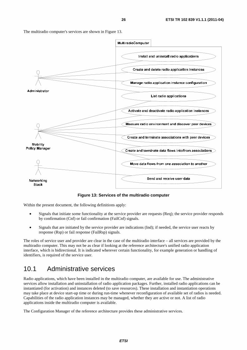
The multiradio computer's services are shown in Figure 13.
Administrator
Mobility
Policy Manager
Networking
Stack
MultiradioComputer
Install and uninstall radio applications
Create and delete radio application instances
Manage radio application instance configuration
Activate and deactivate radio application instances
Measure radio environment and discover peer devices
Create and terminate associations with peer devices
Create and terminate data flows into/from associations
Move data flows from one association to another
Send and receive user data
List radio applications
Figure 13: Services of the multiradio computer
Within the present document, the following definitions apply:
• Signals that initiate some functionality at the service provider are requests (Req); the service provider responds by confirmation (Cnf) or fail confirmation (FailCnf) signals.
• Signals that are initiated by the service provider are indications (Ind); if needed, the service user reacts by response (Rsp) or fail response (FailRsp) signals.
The roles of service user and provider are clear in the case of the multiradio interface – all services are provided by the multiradio computer. This may not be as clear if looking at the reference architecture's unified radio application interface, which is bidirectional. It is indicated wherever certain functionality, for example generation or handling of identifiers, is required of the service user.
10.1 Administrative services Radio applications, which have been installed in the multiradio computer, are available for use. The administrative services allow installation and uninstallation of radio application packages. Further, installed radio applications can be instantiated (for activation) and instances deleted (to save resources). These installation and instantiation operations may take place at device start-up time or during run-time whenever reconfiguration of available set of radios is needed. Capabilities of the radio application instances may be managed, whether they are active or not. A list of radio applications inside the multiradio computer is available.
The Configuration Manager of the reference architecture provides these administrative services.

ETSI
ETSI TR 102 839 V1.1.1 (2011-04) 27
10.1.1 Install radio application
Figure 14: Install radio application signalling diagram
The radio application installation procedure goes as follows:
• The Administrator user gives the radio application package to the Configuration Manager using InstallRadioApplicationReq.
• CM evaluates the radio application package authentication and compatibility, and performs installation if evaluation checks succeed.
• If the application is successfully installed, CM replies with InstallRadioApplicationCnf including a handle (id) to the installed radio application. Otherwise InstallRadioApplicationFailCnf is sent with appropriate reason why the installation failed.
10.1.2 Uninstall radio application
Figure 15: Uninstall radio application signalling diagram
The radio application uninstalling procedure goes as follows:
• The Administrator user sends UninstallRadioApplicationReq to the CM with the handle of an installed radio application package.
• The CM deactivates the radio application instances (in case there are active ones), deletes them if necessary, and then performs uninstallation.
• The CM replies with UninstallRadioApplicationCnf.

ETSI
ETSI TR 102 839 V1.1.1 (2011-04) 28
10.1.3 Create radio application instance
Figure 16: Instantiate radio application signalling diagram
The radio application instantiation procedure goes as follows:
• The Administrator user sends InstantiateRadioApplicationReq to the CM with the handle of an installed radio application package.
• CM evaluates the resource demand of the radio application and the limitations of the amount of instances, and creates a new instance if evaluation checks succeed.
• If the application instance is successfully created, CM replies with InstantiateRadioApplicationCnf including a handle (id) to the new radio application instance.
NOTE: This is different from the handle/identifier of the radio application package). Otherwise InstantiateRadioApplicationFailCnf is sent with appropriate reason why the instantiation failed.
10.1.4 Delete radio application instance
Figure 17: Delete radio application instance signalling diagram

ETSI
ETSI TR 102 839 V1.1.1 (2011-04) 29
The deletion of a radio application instance goes as follows:
• The Administrator user sends DeleteRadioApplicationReq to the CM with the handle of a radio application instance.
• The CM deactivates the radio application instance (in case it is active), and then deletes the instance.
• The CM replies with DeleteRadioApplicationCnf.
NOTE: Deletion of an instance cannot fail.
10.1.5 Get radio application parameters
GetRadioParameters
alt
alt
alt
: Administrator : CM
GetRadioParameterReq(R1:id)
GetRadioParameterCnf(R1:id,ParameterList)
P1 : Radio
ApplicationPackage
Installed
R1 :
RadioApplication
GetRadioParameterFailCnf(Reason)
GetRadioParameterFailCnf(Reason)
GetRadioParameterCnf(R1:id,M1:Parameter,Value)
GetRadioParameterReq(R1:id,M1:Parameter)
Figure 18: Get radio application parameters signalling diagram
The procedure of getting the parameters and parameter values of a radio application instance goes as follows:
• The Administrator user sends GetRadioParameterReq to the CM with the handle of a radio application instance along with the wanted parameters (or none, if all parameters are desired).
• CM evaluates the existence of the instance and the parameters, and the values of the parameters.
• If successful, CM replies with GetRadioParameterCnf including the parameters and their values. Otherwise GetRadioParameterFailCnf is sent with an appropriate failure reason.

ETSI
ETSI TR 102 839 V1.1.1 (2011-04) 30
10.1.6 Set radio application parameters
Figure 19: Set radio application parameters signalling diagram
The procedure of setting the parameters and parameter values of a radio application instance goes as follows:
• The Administrator user sends SetRadioParameterReq to the CM with the handle of a radio application instance along with the wanted parameters and their new values.
• CM evaluates the existence of the instance and the parameters, and that the values of the parameters are within the capabilities (bounds).
• If successful, CM sets the new parameter values and replies with SetRadioParameterCnf. Otherwise SetRadioParameterFailCnf is sent with appropriate reason why the setting failed.
10.1.7 List radio applications
ListRadioApplications
alt
: Mobility
PolicyManager: Administrator : CM
ListRadioApplicationsReq()
ListRadioApplicationsCnf(RadioApplicationList)
ListRadioApplicationsReq()
ListRadioApplicationsCnf(RadioApplicationList)
Figure 20: List radio applications signalling diagram
The procedure of listing the radio applications available in the multiradio computer goes as follows:
• The Administrator or the Mobility Policy Manager user sends ListRadioApplicationsReq to the CM.
• CM checks the installed radio applications, their instances and administrative states, and returns this information with ListRadioApplicationsCnf.

ETSI
ETSI TR 102 839 V1.1.1 (2011-04) 31
10.2 Access control services Access control services represent the multiradio control plane functionality, and are available for radio application instances, not for radio application packages. Further, other access control services than activation are only available for active radio application instances. The Radio Connection Manager of the mobile device reference architecture provides these services.
Three categories of access control services are available: monitoring the radio environment and discovering peer communication equipment, establishing associations to these peer communication equipment, and establishing user data flows to the associations (including moving of data flow from one association to another, within restrictions, possibly even to an association of another radio application).
10.2.1 Activate a radio application instance
Figure 21: Activate radio application instance signalling diagram
The activation procedure of a radio application instance goes as follows:
• The Mobility Policy Manager user sends ActivateReq to the RCM with a handle of a radio application instance.
• RCM checks the administrative state of the application instance, and tries activation if the instance is not yet active. If the activation is successful, ActivateCnf is returned to the Mobility Policy Manager, otherwise ActivateFailCnf is sent with the reason of failure indicated.
NOTE: The activation of the radio application might fail due to resource limitations.
10.2.2 Deactivate a radio application instance
Figure 22: Deactivate radio application instance signalling diagram
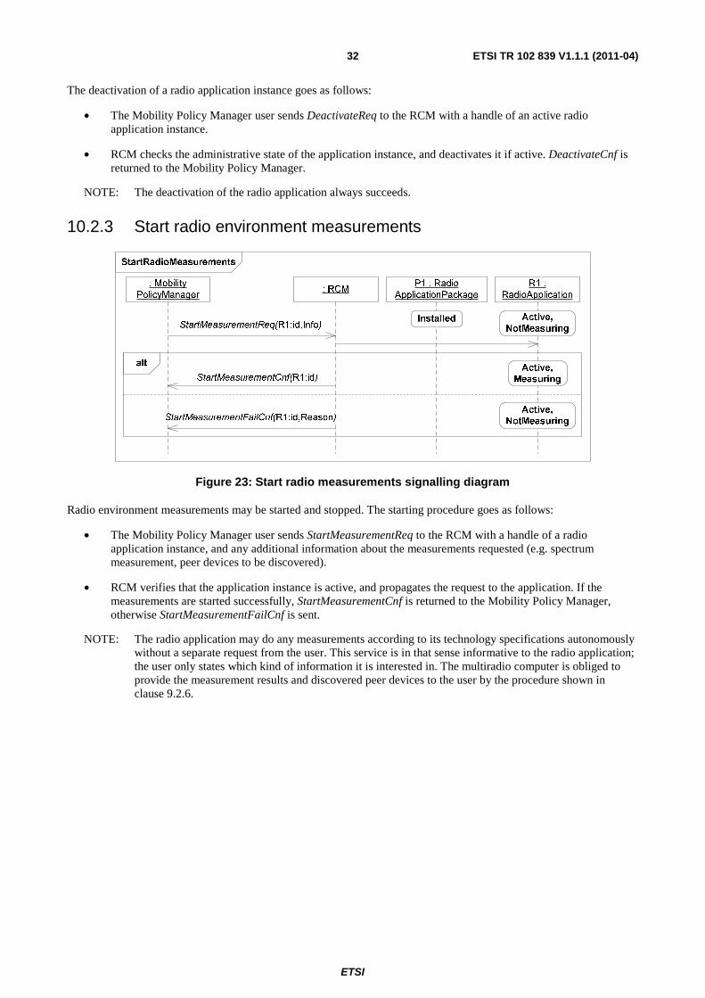
ETSI
ETSI TR 102 839 V1.1.1 (2011-04) 32
The deactivation of a radio application instance goes as follows:
• The Mobility Policy Manager user sends DeactivateReq to the RCM with a handle of an active radio application instance.
• RCM checks the administrative state of the application instance, and deactivates it if active. DeactivateCnf is returned to the Mobility Policy Manager.
NOTE: The deactivation of the radio application always succeeds.
10.2.3 Start radio environment measurements
Figure 23: Start radio measurements signalling diagram
Radio environment measurements may be started and stopped. The starting procedure goes as follows:
• The Mobility Policy Manager user sends StartMeasurementReq to the RCM with a handle of a radio application instance, and any additional information about the measurements requested (e.g. spectrum measurement, peer devices to be discovered).
• RCM verifies that the application instance is active, and propagates the request to the application. If the measurements are started successfully, StartMeasurementCnf is returned to the Mobility Policy Manager, otherwise StartMeasurementFailCnf is sent.
NOTE: The radio application may do any measurements according to its technology specifications autonomously without a separate request from the user. This service is in that sense informative to the radio application; the user only states which kind of information it is interested in. The multiradio computer is obliged to provide the measurement results and discovered peer devices to the user by the procedure shown in clause 9.2.6.

ETSI
ETSI TR 102 839 V1.1.1 (2011-04) 33
10.2.4 Stop radio environment measurements
Figure 24: Stop radio measurements signalling diagram
The procedure of stopping radio environment measurements goes as follows:
• The Mobility Policy Manager user sends StopMeasurementReq to the RCM with a handle of a radio application instance.
• RCM verifies that the application instance is active, and propagates the request to the application. StopMeasurementCnf is returned to the Mobility Policy Manager. The procedure shown in clause 9.2.6 no longer takes place.
10.2.5 Radio environment measurement indication
Figure 25: Radio measurement indication signalling diagram
The radio measurements are indicated to the user as follows:
• Radio measurement indications are only given if a user has requested the radio application measurements using StartMeasurementReq.
• Once measurement results are available, the RCM sends to the Mobility Policy Manager user MeasurementInd with the handle of the radio application instance, and the measurement information.

ETSI
ETSI TR 102 839 V1.1.1 (2011-04) 34
10.2.6 Create association with peer, mobile device originated
CreateAssociation-MobileOriginated
opt
alt
opt
opt
opt
: Mobility
PolicyManager: RCM
AssociateReq(R1:id,D1:Peer)
P1 : Radio
ApplicationPackage
Installed
R1 :
RadioApplication
D1 :
PeerDevice
Active
Communication request
Communication
Communication confirmation
Communication
Association Established
AssociateCnf(R1:id,A1:id)
AssociateFailCnf(R1:id,Reason)
Communication rejection
Communication
Association Failed
Figure 26: Create mobile device originated association signalling diagram
Establishing a mobile device originated association to a peer device goes as follows:
• The Mobility Policy Manager user sends AssociateReq to the RCM with a handle of a radio application instance, and the identification of the desired peer device.
NOTE 1: The identification of the peer device may be known through previous interactions, or by measurements done previously.
• RCM verifies that the application instance is active, and propagates the request to the application. The radio application tries to establish the association to the requested peer device.
• If successful, AssociateCnf is returned to the Mobility Policy Manager with an association identifier.
NOTE 2: this identifier is different from the radio application identifier. Otherwise AssociateFailCnf is sent along with a reason why the association failed.

ETSI
ETSI TR 102 839 V1.1.1 (2011-04) 35
10.2.7 Create association with peer, peer device originated
Figure 27: Create peer device originated association signalling diagram
Establishing a peer device originated association to a peer device goes as follows:
• The RCM sends an AssociateInd to the Mobility Policy Manager with the handle of the radio application instance, a handle to the association, and the identification of the desired peer device.
• The Mobility Policy Manager replies either with AssociateRsp, in which case the association will be established, or AssociateFailRsp, in which case the association is rejected.
• In case the association establishment fails after an AssociateRsp, RCM sends a DisassociateInd with reason of failure.

ETSI
ETSI TR 102 839 V1.1.1 (2011-04) 36
10.2.8 Terminate association, mobile device originated
Figure 28: Mobile device originated disassociation signalling diagram
Terminating an association to a peer device goes as follows:
• The Mobility Policy Manager user sends a DisassociateReq to the RCM with a handle of the association.
• RCM verifies that the application instance is active, and propagates the request to the application. The radio application terminates the association. RCM returns DisassociateCnf to the Mobility Policy Manager.
10.2.9 Terminate association, peer device originated
Figure 29: Peer device originated disassociation signalling diagram
Peer device originated termination of an association goes as follows:
• RCM sends a DisassociateInd to the Mobility Policy Manager with the handle of the association and a reason for disassociation.
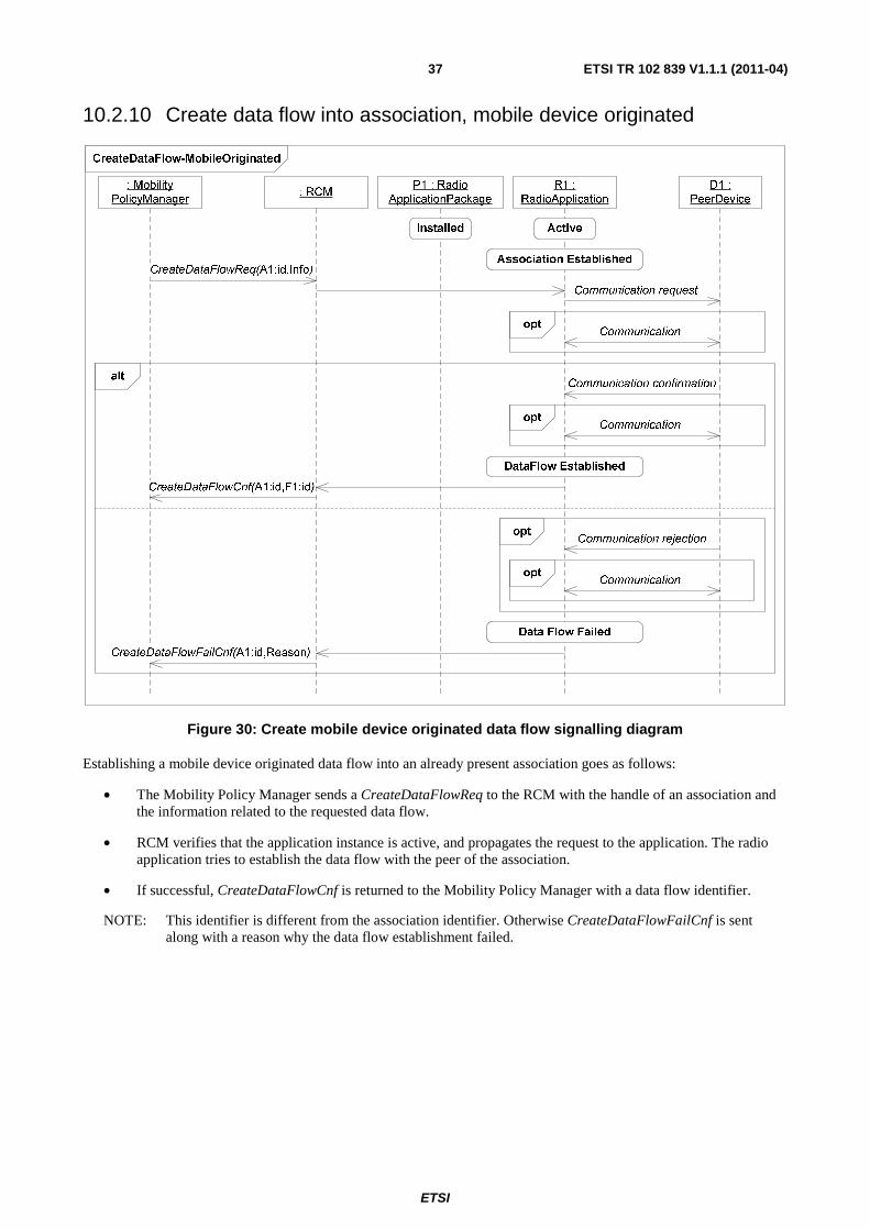
ETSI
ETSI TR 102 839 V1.1.1 (2011-04) 37
10.2.10 Create data flow into association, mobile device originated
Figure 30: Create mobile device originated data flow signalling diagram
Establishing a mobile device originated data flow into an already present association goes as follows:
• The Mobility Policy Manager sends a CreateDataFlowReq to the RCM with the handle of an association and the information related to the requested data flow.
• RCM verifies that the application instance is active, and propagates the request to the application. The radio application tries to establish the data flow with the peer of the association.
• If successful, CreateDataFlowCnf is returned to the Mobility Policy Manager with a data flow identifier.
NOTE: This identifier is different from the association identifier. Otherwise CreateDataFlowFailCnf is sent along with a reason why the data flow establishment failed.

ETSI
ETSI TR 102 839 V1.1.1 (2011-04) 38
10.2.11 Create data flow into association, peer device originated
CreateDataFlow-PeerOriginated
alt
opt
alt
opt
opt
: Mobility
PolicyManager: RCM
CreateDataFlowInd(A1:id,F1:id,Info)
P1 : Radio
ApplicationPackage
Installed
R1 :
RadioApplication
D1 :
PeerDevice
Active
Communication request
Communication
Communication confirmation
Communication
Data Flow Established
DeleteDataFlowInd(F1:id,Reason)
Communication
CreateDataFlowRsp(F1:id)
Data Flow Failed
CreateDataFlowFailRsp(F1:id,Reason)
Communication rejection
Data Flow Failed
Association Established
optCommunication
Figure 31: Create peer device originated data flow signalling diagram
Establishing a peer device originated data flow into an already present association goes as follows:
• The RCM sends a CreateDataFlowInd to the Mobility Policy Manager with the handle of the association, a handle to the data flow, and further information related to the data flow.
• The Mobility Policy Manager replies either with CreateDataFlowRsp, in which case the data flow will be established, or CreateDataFlowFailRsp, in which case the data flow is rejected.
• In case the data flow establishment fails after a CreateDataFlowRsp, RCM sends a DeleteDataFlowInd with reason of failure.

ETSI
ETSI TR 102 839 V1.1.1 (2011-04) 39
10.2.12 Terminate data flow, mobile device originated
Figure 32: Mobile device originated data flow termination signalling diagram
Terminating a data flow from an association goes as follows:
• The Mobility Policy Manager user sends a DeleteDataFlowReq to the RCM with a handle of the data flow.
• RCM verifies that the appropriate application instance is active, and propagates the request to the application. The radio application terminates the data flow. RCM returns DeleteDataFlowCnf to the Mobility Policy Manager.
10.2.13 Terminate data flow, peer device originated
Figure 33: Peer device originated data flow termination signalling diagram
Peer device originated termination of a data flow goes as follows:
• RCM sends a DeleteDataFlowInd to the Mobility Policy Manager with the handle of the data flow and a reason for termination.

ETSI
ETSI TR 102 839 V1.1.1 (2011-04) 40
10.2.14 Move data flow from association into another
Figure 34: Moving of data flow from one association into another signalling diagram
The moving of a data flow goes as follows:
• The Mobility Policy Manager user sends a MoveDataFlowReq to the RCM with the handle of a data flow, and the handle of the association into which the data flow is to be moved.
• RCM verifies that the appropriate association exists, and moves the data flow to that association.
If successful, MoveDataFlowCnf is returned to the Mobility Policy Manager. Otherwise MoveDataFlowFailCnf is returned along with a reason why the moving failed.
10.3 Data flow services
10.3.1 Send user data
Figure 35: Send user data signalling diagram

ETSI
ETSI TR 102 839 V1.1.1 (2011-04) 41
Sending user data through an existing data flow goes as follows:
• Networking Stack sends a DataReq to the Flow Controller with the handle of the data flow, and user data to be sent.
• Flow Controller may respond with DataCnf or DataFailCnf depending on the success of the radio channel delivery (typically only Medium Access Control level acknowledgements are possible when using radio channel).
10.3.2 Receive user data
Figure 36: Receive user data signalling diagram
Receiving user data goes as follows:
• Flow Controller sends a DataInd to the Networking Stack with the handle of the data flow, and the received user data.

ETSI
ETSI TR 102 839 V1.1.1 (2011-04) 42
History
Document history
V1.1.1 April 2011 Publication