tr 100 028-2 - v1.4.1 - electromagnetic …...2001/01/04 · annex c: interpretation of the...
TRANSCRIPT

ETSI TR 100 028-2 V1.4.1 (2001-12)
Technical Report
Electromagnetic compatibilityand Radio spectrum Matters (ERM);
Uncertainties in the measurementof mobile radio equipment characteristics;
Part 2

ETSI
ETSI TR 100 028-2 V1.4.1 (2001-12)2
Reference RTR/ERM-RP02-058-2
Keywords measurement uncertainty, mobile, radio
ETSI
650 Route des Lucioles F-06921 Sophia Antipolis Cedex - FRANCE
Tel.: +33 4 92 94 42 00 Fax: +33 4 93 65 47 16
Siret N° 348 623 562 00017 - NAF 742 C
Association à but non lucratif enregistrée à la Sous-Préfecture de Grasse (06) N° 7803/88
Important notice
Individual copies of the present document can be downloaded from: http://www.etsi.org
The present document may be made available in more than one electronic version or in print. In any case of existing or perceived difference in contents between such versions, the reference version is the Portable Document Format (PDF).
In case of dispute, the reference shall be the printing on ETSI printers of the PDF version kept on a specific network drive within ETSI Secretariat.
Users of the present document should be aware that the document may be subject to revision or change of status. Information on the current status of this and other ETSI documents is available at
http://portal.etsi.org/tb/status/status.asp
If you find errors in the present document, send your comment to: [email protected]
Copyright Notification
No part may be reproduced except as authorized by written permission. The copyright and the foregoing restriction extend to reproduction in all media.
© European Telecommunications Standards Institute 2001.
All rights reserved.

ETSI
ETSI TR 100 028-2 V1.4.1 (2001-12)3
Contents
Intellectual Property Rights ................................................................................................................................9
Foreword.............................................................................................................................................................9
Introduction ........................................................................................................................................................9
1 Scope ......................................................................................................................................................11
2 References ..............................................................................................................................................11
3 Definitions, symbols and abbreviations .................................................................................................11 3.1 Definitions........................................................................................................................................................11 3.2 Symbols............................................................................................................................................................15 3.3 Abbreviations ...................................................................................................................................................18
4 Receiver measurement examples ...........................................................................................................18 4.1 Conducted.........................................................................................................................................................19 4.1.1 Maximum usable sensitivity .......................................................................................................................19 4.1.1.1 Maximum usable sensitivity for analogue speech.................................................................................19 4.1.1.2 Maximum usable sensitivity for a bit stream ........................................................................................21 4.1.1.3 Maximum usable sensitivity for messages ............................................................................................24 4.1.2 Co-channel rejection ...................................................................................................................................26 4.1.2.1 Co-channel rejection for analogue speech.............................................................................................26 4.1.2.2 Co-channel rejection for bit stream.......................................................................................................30 4.1.2.3 Co-channel rejection for messages........................................................................................................34 4.1.3 Adjacent channel selectivity .......................................................................................................................36 4.1.3.1 Adjacent channel selectivity for analogue speech.................................................................................36 4.1.3.2 Adjacent channel selectivity for bit streams..........................................................................................36 4.1.3.3 Adjacent channel selectivity for messages ............................................................................................37 4.1.4 Spurious response immunity.......................................................................................................................37 4.1.4.1 Spurious response immunity measurements for analogue speech.........................................................37 4.1.4.1.1 In band measurements .....................................................................................................................37 4.1.4.1.2 Out of band measurements ..............................................................................................................41 4.1.4.2 Spurious response immunity measurements for bit stream...................................................................45 4.1.4.2.1 In band measurements .....................................................................................................................46 4.1.4.2.2 Out of band measurements ..............................................................................................................49 4.1.4.3 Spurious response immunity measurements for messages....................................................................53 4.1.4.3.1 In band measurements .....................................................................................................................53 4.1.4.3.2 Out of band measurements ..............................................................................................................55 4.1.5 Intermodulation immunity ..........................................................................................................................57 4.1.5.1 Intermodulation immunity (analogue speech).......................................................................................57 4.1.5.2 Intermodulation immunity (bit stream) .................................................................................................62 4.1.5.3 Intermodulation immunity (messages) ..................................................................................................68 4.1.6 Blocking immunity or desensitization ........................................................................................................75 4.1.6.1 Blocking immunity or desensitization for analogue speech..................................................................75 4.1.6.2 Blocking immunity or desensitization for bit streams...........................................................................75 4.1.6.3 Blocking immunity or desensitization for messages .............................................................................75 4.1.7 Conducted spurious emissions....................................................................................................................76 4.1.8 Amplitude characteristic for analogue speech ............................................................................................79 4.1.9 Audio frequency response for analogue speech..........................................................................................81 4.1.10 Harmonic distortion for analogue speech ...................................................................................................81 4.1.11 Hum and noise for analogue speech ...........................................................................................................81 4.1.12 Multi-path sensitivity..................................................................................................................................81 4.1.13 Bit error ratio ..............................................................................................................................................81 4.1.14 Opening delay for data................................................................................................................................82 4.2 Radiated............................................................................................................................................................82 4.2.1 Sensitivity tests (30 MHz to 1 000 MHz) ...................................................................................................82 4.2.1.1 Anechoic Chamber................................................................................................................................82 4.2.1.1.1 Uncertainty contributions: Stage one: Determination of Transform Factor ....................................82

ETSI
ETSI TR 100 028-2 V1.4.1 (2001-12)4
4.2.1.1.2 Uncertainty contributions: Stage two: EUT measurement ..............................................................83 4.2.1.1.3 Expanded uncertainty of the receiver sensitivity measurement.......................................................84 4.2.1.2 Anechoic Chamber with a ground plane ...............................................................................................84 4.2.1.2.1 Uncertainty contributions: Stage one: Determination of Transform Factor ....................................84 4.2.1.2.2 Uncertainty contributions: Stage two: EUT measurement ..............................................................86 4.2.1.2.3 Expanded uncertainty of the receiver sensitivity measurement.......................................................87 4.2.1.3 Open Area Test Site ..............................................................................................................................87 4.2.1.3.1 Uncertainty contributions: Stage one: Transform Factor.................................................................87 4.2.1.3.2 Uncertainty contributions: Stage two: EUT measurement ..............................................................88 4.2.1.3.3 Expanded uncertainty of the receiver sensitivity measurement.......................................................89 4.2.1.4 Striplines ...............................................................................................................................................89 4.2.1.4.1 Uncertainty contributions: Stage 1: EUT measurement ..................................................................89 4.2.1.4.2 Uncertainty contributions: Stage 2: Field measurement..................................................................90 4.2.1.4.3 Expanded uncertainty for the Receiver sensitivity measurement ....................................................92 4.2.1.5 Test Fixture ...........................................................................................................................................92 4.2.1.5.1 Uncertainty contributions ................................................................................................................92 4.2.1.5.2 Expanded uncertainty of the Maximum usable sensitivity measurement ........................................93 4.2.1.6 Salty Man/Salty lite...............................................................................................................................93 4.2.1.6.1 Anechoic Chamber ..........................................................................................................................93 4.2.1.6.2 Anechoic Chamber with a ground plane..........................................................................................95 4.2.1.6.3 Open Area Test Site.........................................................................................................................98 4.2.2 Co-channel rejection .................................................................................................................................100 4.2.2.1 Test fixture ..........................................................................................................................................100 4.2.2.1.1 Uncertainty contributions ..............................................................................................................101 4.2.2.1.2 Expanded uncertainty ....................................................................................................................101 4.2.3 Adjacent channel selectivity .....................................................................................................................101 4.2.3.1 Test fixture ..........................................................................................................................................101 4.2.3.1.1 Uncertainty contributions ..............................................................................................................101 4.2.3.1.2 Expanded uncertainty ....................................................................................................................102 4.2.4 Intermodulation immunity ........................................................................................................................102 4.2.4.1 Test fixture ..........................................................................................................................................102 4.2.4.1.1 Uncertainty contributions ..............................................................................................................102 4.2.4.1.2 Expanded uncertainty ....................................................................................................................102 4.2.5 Blocking immunity or degradation ...........................................................................................................103 4.2.5.1 Test fixture ..........................................................................................................................................103 4.2.5.1.1 Uncertainty contributions ..............................................................................................................103 4.2.5.1.2 Expanded uncertainty ....................................................................................................................103 4.2.6 Spurious response immunity to radiated fields .........................................................................................103 4.2.6.1 Anechoic chamber...............................................................................................................................103 4.2.6.1.1 Uncertainty contributions: Stage 1: Transform Factor ..................................................................103 4.2.6.1.2 Uncertainty contributions: Stage 2: EUT measurement ................................................................105 4.2.6.1.3 Expanded uncertainty ....................................................................................................................106
Annex A: Uncertainty contributions ..................................................................................................107
Annex B: Maximum accumulated measurement uncertainty .........................................................143
Annex C: Interpretation of the measurement results .......................................................................144
Annex D: Theoretical support for the evaluation of measurement uncertainties, including mathematical tools and properties of distributions .........................................................145
D.1 Probability densities and some of their properties ...............................................................................145 D.1.1 Introduction ....................................................................................................................................................145 D.1.2 Definitions......................................................................................................................................................145 D.1.3 Means and standard deviations of usual distributions ....................................................................................148 D.1.3.1 Rectangular distributions ..........................................................................................................................148 D.1.3.2 Triangular distributions.............................................................................................................................148 D.1.3.2.1 Additive combination of two rectangular distributions having the same spread.................................149 D.1.3.2.2 Properties of triangular distributions...................................................................................................149 D.1.3.3 Trapezoidal distributions ..........................................................................................................................150 D.1.3.3.1 Symmetrical trapezoidal distributions.................................................................................................150

ETSI
ETSI TR 100 028-2 V1.4.1 (2001-12)5
D.1.3.3.2 Non symmetrical trapezoidal distributions..........................................................................................151 D.1.3.4 Gaussian distributions...............................................................................................................................151 D.1.3.5 Oblique pseudo-Gaussian distributions ....................................................................................................154 D.1.3.6 'U' shaped distributions .............................................................................................................................154 D.1.3.6.1 Can this be the expression of a probability density? ...........................................................................154 D.1.3.6.2 Variance ..............................................................................................................................................155 D.1.3.7 Maximum value of the standard deviation for bound distributions ..........................................................157 D.1.3.8 Standard deviation for bound distributions (summary table)....................................................................158
D.2 Uncertainties and probability densities ................................................................................................158 D.2.1 Examples of very simple systems and corresponding naïve (direct) analysis ................................................159 D.2.1.1 Ohm's law .................................................................................................................................................159 D.2.1.1.1 Relations between Random Variables under Ohm's law.....................................................................159 D.2.1.1.1.1 Establishing the Relations between Random Variables.................................................................159 D.2.1.1.1.2 Verifications concerning Ohm's law..............................................................................................160 D.2.1.1.2 Uncertainties and the usage of Ohm's law...........................................................................................160 D.2.1.1.3 Examples concerning Ohm's law using particular distributions..........................................................161 D.2.1.1.3.1 Rectangular distributions and the corresponding interpretation of uncertainties...........................161 D.2.1.1.3.2 Gaussian distributions and the corresponding interpretation of uncertainties ...............................162 D.2.1.2 A basic voltmeter ......................................................................................................................................163 D.2.1.2.1 Building a multi-range voltmeter ........................................................................................................164 D.2.1.2.2 Correlations between measurements with different voltmeters...........................................................164 D.2.1.3 Adding voltages ........................................................................................................................................165 D.2.1.4 The Wheatstone Bridge ............................................................................................................................165 D.2.1.4.1 Fully balanced Bridge .........................................................................................................................166 D.2.1.4.2 Bridge not fully balanced ....................................................................................................................167 D.2.1.5 Influence of temperature ...........................................................................................................................170 D.2.2 Modelling instruments....................................................................................................................................170 D.2.3 Comparison with worst case methods ............................................................................................................171 D.2.4 Independent or not …that is the question!......................................................................................................171 D.2.4.1 Different effects ........................................................................................................................................171 D.2.4.2 Making the right choices...........................................................................................................................171
D.3 Combination of distributions................................................................................................................172 D.3.1 Addition of a constant to a random variable...................................................................................................172 D.3.1.1 Evaluation of the corresponding distribution............................................................................................173 D.3.1.2 Verification ...............................................................................................................................................173 D.3.1.3 Means and standard deviations .................................................................................................................174 D.3.1.4 Examples of usage ....................................................................................................................................174 D.3.1.5 Examples of conversion............................................................................................................................174 D 3.2 Multiplication of a random variable by a constant factor ...............................................................................174 D.3.2.1 Evaluation of the corresponding distribution............................................................................................175 D.3.2.1.1 Case λλλλ positive ...................................................................................................................................175 D.3.2.1.2 Case λλλλ negative ...................................................................................................................................176 D.3.2.1.3 Conclusion ..........................................................................................................................................176 D.3.2.2 Verifications .............................................................................................................................................176 D.3.2.3 Means and standard deviations .................................................................................................................177 D.3.2.4 Examples of usage ....................................................................................................................................177 D.3.2.5 Examples of conversions ..........................................................................................................................177 D.3.3 Sums (additions) of random variables ............................................................................................................177 D.3.3.1 Evaluation of the corresponding distribution............................................................................................178 D.3.3.2 Verifications .............................................................................................................................................179 D.3.3.3 Means and standard deviations .................................................................................................................180 D.3.3.4 Examples ..................................................................................................................................................180 D.3.3.5 Adding several distributions .....................................................................................................................180 D.3.3.5.1 Adding Normal distributions...............................................................................................................180 D.3.3.5.1.1 Using the expressions giving the probability density ....................................................................180 D.3.3.5.1.1.1 Case where two identical Normal distributions are added .......................................................180 D.3.3.5.1.1.2 Case where two identical Normal distributions with different offsets are added.....................182 D.3.3.5.1.1.3 Case of two Normal distributions having different standard deviations ..................................184 D.3.3.5.1.1.4 Case of two different Normal distributions..............................................................................186 D.3.3.5.1.1.5 Conclusion ...............................................................................................................................187

ETSI
ETSI TR 100 028-2 V1.4.1 (2001-12)6
D.3.3.5.1.2 Example of application..................................................................................................................187 D.3.3.5.2 Adding several rectangular distributions.............................................................................................189 D.3.3.5.2.1 Adding several rectangular distributions having the same parameter ...........................................189 D.3.3.5.2.2 Adding several rectangular distributions having different parameters ..........................................190 D.3.4 Linear combinations of random variables ......................................................................................................191 D.3.4.1 Evaluation of the corresponding distribution............................................................................................191 D.3.4.1.1 Using a direct method .........................................................................................................................191 D.3.4.1.2 Using the "Building blocs" method.....................................................................................................191 D.3.4.2 Verification ...............................................................................................................................................191 D.3.4.3 Means and standard deviations .................................................................................................................192 D.3.4.4 Examples ..................................................................................................................................................192 D.3.4.5 Extrapolation.............................................................................................................................................192 D.3.4.5.1 Extrapolation in the general case ........................................................................................................192 D.3.4.5.2 Extrapolation in a particular case (RSSing) ........................................................................................192 D.3.4.5.3 Using differentiation ...........................................................................................................................192 D.3.4.6 Case of non independent random variables ..............................................................................................193 D.3.4.6.1 Comparison between results................................................................................................................193 D.3.4.6.2 Conclusions.........................................................................................................................................194 D.3.5 Subtraction of random variables.....................................................................................................................194 D.3.5.1 Evaluation of the corresponding distribution............................................................................................194 D.3.5.2 Verifications .............................................................................................................................................195 D.3.5.3 Means and standard deviations .................................................................................................................196 D.3.5.3.1 Mean value..........................................................................................................................................196 D.3.5.3.2 Standard deviation...............................................................................................................................197 D.3.5.4 Examples ..................................................................................................................................................198 D.3.5.5 Subtracting several distributions...............................................................................................................198 D.3.6 Multiplication of random variables ................................................................................................................198 D.3.6.1 Evaluation of the corresponding distribution............................................................................................199 D.3.6.2 Verifications .............................................................................................................................................201 D.3.6.3 Means and standard deviations .................................................................................................................201 D.3.6.4 Examples ..................................................................................................................................................203 D.3.6.5 Extrapolations ...........................................................................................................................................203 D.3.7 Inversions and divisions .................................................................................................................................203 D.3.7.1 Evaluation of distributions corresponding to inversions...........................................................................203 D.3.7.2 Verification in the case of the inversion ...................................................................................................204 D.3.7.3 Means and standard deviations in the case of the inversion .....................................................................205 D.3.7.3.1 Mean value..........................................................................................................................................205 D.3.7.3.2 Comment concerning the mean value .................................................................................................206 D.3.7.3.3 Standard deviation...............................................................................................................................206 D.3.7.4 Examples of inversions .............................................................................................................................207 D.3.7.4.1 Evaluation of the distribution..............................................................................................................207 D.3.7.4.2 Evaluation of the mean value ..............................................................................................................207 D.3.7.4.3 Evaluation of the standard deviation ...................................................................................................208 D.3.7.4.4 Comments concerning the standard deviation.....................................................................................209 D.3.7.5 Evaluation of the distribution corresponding to divisions ........................................................................210 D.3.7.6 Verification in the case of divisions..........................................................................................................211 D.3.7.7 Means and standard deviations in the case of divisions............................................................................212 D.3.7.7.1 Corresponding evaluation ...................................................................................................................212 D.3.7.7.2 Comments ...........................................................................................................................................213 D.3.7.8 Examples in the case of divisions .............................................................................................................214 D.3.8 Using Logs and dBs .......................................................................................................................................214 D.3.8.1 Evaluation of the corresponding distribution............................................................................................214 D.3.8.2 Verifications .............................................................................................................................................215 D.3.8.3 Mathematical support for calculations with Logs and dBs .......................................................................215 D.3.8.4 Using dBs .................................................................................................................................................216 D.3.8.4.1 Transformation of linear terms into dBs .............................................................................................217 D.3.8.4.1.1 Converting powers into dBs ..........................................................................................................217 D.3.8.4.1.2 Converting a rectangular distribution into dBs..............................................................................218 D.3.8.4.1.3 Converting voltages in dBs............................................................................................................218 D.3.8.4.2 Transformation of dBs into linear terms .............................................................................................219 D.3.8.4.2.1 Converting powers.........................................................................................................................219 D.3.8.4.2.2 Converting Voltages ......................................................................................................................220

ETSI
ETSI TR 100 028-2 V1.4.1 (2001-12)7
D.3.8.4.2.3 Converting rectangular distributions .............................................................................................220 D.3.8.4.3 Examples.............................................................................................................................................220 D.3.8.4.3.1 Evaluation of uncertainties ............................................................................................................220 D.3.8.4.3.2 Evaluation of link budgets.............................................................................................................221 D.3.8.4.3.3 Usage in the case of evaluation of link budgets and interference ..................................................221 D.3.9 Combination using deterministic functions of one variable ...........................................................................221 D.3.9.1 Evaluation of the corresponding distribution............................................................................................222 D.3.9.2 Verifications .............................................................................................................................................223 D.3.9.3 Means and standard deviations .................................................................................................................223 D.3.9.4 Examples ..................................................................................................................................................224 D.3.10 Further theoretical material and reciprocals ...................................................................................................224 D.3.10.1 Integrals and derivatives ...........................................................................................................................225 D.3.10.2 Substitutions and integrals ........................................................................................................................225 D.3.10.3 Substitutions and distributions..................................................................................................................226 D.3.10.4 Example of application: the inverse..........................................................................................................227 D.3.10.5 Reciprocals ...............................................................................................................................................227 D.3.10.6 Notations...................................................................................................................................................228 D.3.10.7 Units..........................................................................................................................................................229 D.3.10.7.1 Some properties...................................................................................................................................229 D.3.10.7.2 Example ..............................................................................................................................................229 D.3.10.8 Application of the substitution method in difficult situations...................................................................230 D.3.10.9 From the time domain to density probabilities .........................................................................................230 D.3.11 Combinations using deterministic functions of two variables........................................................................230 D.3.11.1 Evaluation of the corresponding distribution............................................................................................230 D.3.11.2 Verifications .............................................................................................................................................232 D.3.11.3 Means and standard deviations .................................................................................................................234 D.3.11.4 Examples ..................................................................................................................................................235 D.3.11.5 Generalization to spaces of dimension N..................................................................................................235 D.3.12 Combination of distributions – Summary table..............................................................................................236
D.4 Influence quantities ..............................................................................................................................238 D.4.1 Theoretical approach ......................................................................................................................................238 D.4.2 Examples ........................................................................................................................................................238 D.4.2.1 Effect of the temperature ..........................................................................................................................238 D.4.2.2 Effect of the temperature on a resistor ......................................................................................................239
D.5 Global approaches ................................................................................................................................240 D.5.1 Using directly the random variables in a measurement..................................................................................240 D.5.1.1 Introduction...............................................................................................................................................240 D.5.1.2 Writing the equations................................................................................................................................240 D.5.1.3 Number of equations.................................................................................................................................241 D.5.1.4 Mapping variables ....................................................................................................................................241 D.5.1.5 Conclusions...............................................................................................................................................241 D.5.2 Using random variables together with differentiation in a measurement .......................................................241 D.5.3 Examples of application to particular cases ...................................................................................................243 D.5.3.1 Using random variables together with differentiation in a measurement, case of multiplicative
functions ...................................................................................................................................................243 D.5.3.2 Substitution measurements .......................................................................................................................243 D.5.4 Empirical approach to find a model of the system .........................................................................................244 D.5.5 Splitting into sub-systems ..............................................................................................................................245 D.5.6 Presentation and interpretation of results obtained (outputs) .........................................................................246 D.5.6.1 Worst case approach .................................................................................................................................246 D.5.6.2 Probabilistic approach...............................................................................................................................246 D.5.6.2.1 Preliminary comments (and choice of scenario) .................................................................................246 D.5.6.2.2 Summary of the methodology .............................................................................................................247 D.5.6.2.3 Normal and non-Normal distributions ................................................................................................249 D.5.6.2.4 Confidence levels for non-Normal distributions .................................................................................249 D.5.6.2.5 Practical conclusions...........................................................................................................................250 D.5.6.2.6 Implications.........................................................................................................................................250 D.5.6.2.7 Examples (excerpts from available standards) ....................................................................................251 D.5.6.2.7.1 Excerpts from a "Part 1" ................................................................................................................251 D.5.6.2.7.2 Excerpts from a "Part 2" ................................................................................................................252

ETSI
ETSI TR 100 028-2 V1.4.1 (2001-12)8
D.5.6.2.7.3 Excerpts from a "Part 1" showing words used for double sided limits..........................................253 D.5.6.2.8 Confidence levels and single sided limits ...........................................................................................254 D.5.6.3 Conclusions...............................................................................................................................................254 D.5.7 Summary ........................................................................................................................................................254
D.6 Conclusions ..........................................................................................................................................255
Annex E: Mathematical transforms...................................................................................................256
E.1 Principles of derivation of formulas when transforming from log to linear.........................................256 E.1.1 A rectangular distribution in logarithmic terms converted to linear terms .....................................................256 E.1.2 A triangular distribution in logarithmic terms converted to linear terms .......................................................259 E.1.3 A rectangular distribution in linear terms converted to logarithmic terms: ....................................................261
E.2 Conversion factors................................................................................................................................264
Annex F: Influence quantity dependency functions .........................................................................266
Annex G: Mismatch uncertainties ......................................................................................................268
G.1 Introduction ..........................................................................................................................................268 G.1.1 Cascading networks........................................................................................................................................268 G.1.2 Mismatch uncertainty calculations .................................................................................................................272
G.2 General approach..................................................................................................................................275
G.3 Networks comprising power combiners/splitters .................................................................................275
Annex H: Bibliography........................................................................................................................283
History ............................................................................................................................................................285

ETSI
ETSI TR 100 028-2 V1.4.1 (2001-12)9
Intellectual Property Rights IPRs essential or potentially essential to the present document may have been declared to ETSI. The information pertaining to these essential IPRs, if any, is publicly available for ETSI members and non-members, and can be found in ETSI SR 000 314: "Intellectual Property Rights (IPRs); Essential, or potentially Essential, IPRs notified to ETSI in respect of ETSI standards", which is available from the ETSI Secretariat. Latest updates are available on the ETSI Web server (http://webapp.etsi.org/IPR/home.asp).
Pursuant to the ETSI IPR Policy, no investigation, including IPR searches, has been carried out by ETSI. No guarantee can be given as to the existence of other IPRs not referenced in ETSI SR 000 314 (or the updates on the ETSI Web server) which are, or may be, or may become, essential to the present document.
Foreword This Technical Report (TR) has been produced by ETSI Technical Committee Electromagnetic compatibility and Radio spectrum Matters (ERM).
The present document has been split into two parts, due to practical limitations.
In the second edition, the area of data communication measurement uncertainties has been addressed and added to the work on analogue measurement uncertainties found in the first edition of the present document; in addition the diagrams had been standardized and minor editorial corrections had been carried out.
A presentation has been also added in order to provide a general overview of the approach used in the present document (see file "MeasurementUncertainties_V141c.ppt") which is available in tr_10002802v010401p0.zip.
Introduction The present document has been written to clarify the many problems associated with the calculation, interpretation and application of measurement uncertainty and is expected to be used, in particular, by accredited test laboratories performing measurements.
The present document is intended to provide, for the relevant standards, methods of calculating the measurement uncertainty relating to the assessment of the performance of radio equipment. The present document is not intended to replace any test methods in the relevant standards although clauses 5, 6 and 7 (in TR 100 028-1 [6]) contain brief descriptions of each measurement (such descriptions are just intended to support the explanations relating to the evaluation of the uncertainties).
More precisely, the basic purpose of the present document is to:
- provide the method of calculating the total measurement uncertainty (see, in particular annex D and clauses 1 to 5 of TR 100 028-1 [6];
- provide the maximum acceptable "window" of measurement uncertainty (see table B.1), when calculated using the methods described in the present document;
- provide the equipment under test dependency functions (see table F.1) which shall be used in the calculations unless these functions are evaluated by the individual laboratories;
- provide a recommended method of applying the uncertainties in the interpretation of the results (see annex C).
Although the present document has been written in a way to cover a larger spread of equipment than what is actually stated in the scope (in order to help as much as possible) the particular aspects needed regarding some technologies such as TDMA may have been left out, even though the general approach to measurement uncertainties and the theoretical background is, in principle, independent of the technology.
Hence, the present document is applicable to measurement methodology in a broad sense but care should be taken when using it to draft new standards or when applying it to a particular technology such as TDMA or CDMA.

ETSI
ETSI TR 100 028-2 V1.4.1 (2001-12)10
In an attempt to help the user and in order to clarify the particular aspects of each method, a number of examples have been given (including spread sheets relating to clause 7 of TR 100 028-1 [6] and clause 4 of the present document).
However, these examples may have been drafted by different authors. In a number of cases, simplifications may have been introduced (e.g. Log (1 + x) = x: simplifications and, hopefully, not real errors), in order to reach practical conclusions, while avoiding supplementary complications.
As a result, examples covering similar areas may not be fully consistent. The reader is therefore expected to understand fully the theoretical basis underlying the present document (annex D provides the basis for the theoretical approach) and to exercise his own judgement while using the present document.
As a result, under no circumstances, could ETSI be held for responsible for any consequence of the usage of the present document.

ETSI
ETSI TR 100 028-2 V1.4.1 (2001-12)11
1 Scope The present document provides a method to be applied to all the applicable deliverables, and supports TR 100 027 [1].
It covers the following aspects relating to measurements:
a) methods for the calculation of the total uncertainty for each of the measured parameters;
b) recommended maximum acceptable uncertainties for each of the measured parameters;
c) a method of applying the uncertainties in the interpretation of the results.
The present document provides the methods of evaluating and calculating the measurement uncertainties and the required corrections on measurement conditions and results (these corrections are necessary in order to remove the errors caused by certain deviations of the test system due to its known characteristics (such as the RF signal path attenuation and mismatch loss, etc.)).
2 References For the purposes of this Technical Report (TR), the following references apply:
[1] ETSI TR 100 027: "Electromagnetic compatibility and Radio spectrum Matters (ERM); Methods of measurement for private mobile radio equipment".
[2] ETSI TR 102 273 (all parts): "Electromagnetic compatibility and Radio spectrum Matters (ERM); Improvement of radiated methods of measurement (using test sites) and evaluation of the corresponding measurement uncertainties".
[3] ITU-T Recommendation O.41: "Psophometer for use on telephone-type circuits".
[4] EN 55020: "Electromagnetic Immunity of Broadcast Receivers and Associated Equipment".
[5] ETSI ETR 028: "Radio Equipment and Systems (RES); Uncertainties in the measurement of mobile radio equipment characteristics".
[6] ETSI TR 100 028-1: "Electromagnetic compatibility and Radio spectrum Matters (ERM); Uncertainties in the measurement of mobile radio equipment characteristics; Part 1".
3 Definitions, symbols and abbreviations
3.1 Definitions For the purposes of the present document, the following terms and definitions apply:
accuracy: this term is defined, in relation to the measured value, in clause 4.1.1 of TR 100 028-2; it has also been used in the rest of the document in relation to instruments
AF load: is normally a resistor of sufficient power rating to accept the maximum audio output power from the EUT
NOTE: The value of the resistor should be that stated by the manufacturer and should be the impedance of the audio transducer at 1 000 Hz.
In some cases it may be necessary to place an isolating transformer between the output terminals of the receiver under test and the load.

ETSI
ETSI TR 100 028-2 V1.4.1 (2001-12)12
AF termination: any connection other than the audio frequency load which may be required for the purpose of testing the receiver (i.e. in a case where it is required that the bit stream be measured, the connection may be made, via a suitable interface, to the discriminator of the receiver under test)
NOTE: The termination device should be agreed between the manufacturer and the testing authority and details should be included in the test report. If special equipment is required then it should be provided by the manufacturer.
antenna: part of a transmitting or receiving system that is designed to radiate or to receive electromagnetic waves
antenna factor: quantity relating the strength of the field in which the antenna is immersed to the output voltage across the load connected to the antenna
NOTE: When properly applied to the meter reading of the measuring instrument, yields the electric field strength in V/m or the magnetic field strength in A/m.
antenna gain: ratio of the maximum radiation intensity from an (assumed lossless) antenna to the radiation intensity that would be obtained if the same power were radiated isotropically by a similarly lossless antenna
bit error ratio: ratio of the number of bits in error to the total number of bits
combining network: multipole network allowing the addition of two or more test signals produced by different sources (e.g. for connection to a receiver input)
NOTE: Sources of test signals should be connected in such a way that the impedance presented to the receiver should be 50 Ω. The effects of any intermodulation products and noise produced in the signal generators should be negligible.
correction factor: numerical factor by which the uncorrected result of a measurement is multiplied to compensate for an assumed systematic error
confidence level: probability of the accumulated error of a measurement being within the stated range of uncertainty of measurement
directivity: ratio of the maximum radiation intensity in a given direction from the antenna to the radiation intensity averaged over all directions (i.e. directivity = antenna gain + losses)
duplex filter: device fitted internally or externally to a transmitter/receiver combination to allow simultaneous transmission and reception with a single antenna connection
error of measurement (absolute): result of a measurement minus the true value of the measurand
error (relative): ratio of an error to the true value
estimated standard deviation: From a sample of n results of a measurement the estimated standard deviation is given by the formula:
1
1
2
−
−
=∑
=n
)x(xn
i
i
σ
xi being the ith result of measurement (i = 1,2,3, ...,n) and x the arithmetic mean of the n results considered.
A practical form of this formula is:
1
2
−
−=
nn
XY
σ
Where X is the sum of the measured values and Y is the sum of the squares of the measured values.

ETSI
ETSI TR 100 028-2 V1.4.1 (2001-12)13
The term standard deviation has also been used in the present document to characterize a particular probability density. Under such conditions, the term standard deviation may relate to situations where there is only one result for a measurement.
expansion factor: multiplicative factor used to change the confidence level associated with a particular value of a measurement uncertainty
NOTE: The mathematical definition of the expansion factor can be found in clause D.5.6.2.2.
extreme test conditions: defined in terms of temperature and supply voltage
NOTE: Tests should be made with the extremes of temperature and voltage applied simultaneously
The upper and lower temperature limits are specified in the relevant deliverable. The test report should state the actual temperatures measured.
error (of a measuring instrument): indication of a measuring instrument minus the (conventional) true value
free field: field (wave or potential) which has a constant ratio between the electric and magnetic field intensities
free space: region free of obstructions and characterized by the constitutive parameters of a vacuum
impedance: measure of the complex resistive and reactive attributes of a component in an alternating current circuit
impedance (wave): complex factor relating the transverse component of the electric field to the transverse component of the magnetic field at every point in any specified plane, for a given mode
influence quantity: quantity which is not the subject of the measurement but which influences the value of the quantity to be measured or the indications of the measuring instrument
intermittent operation: manufacturer should state the maximum time that the equipment is intended to transmit and the necessary standby period before repeating a transmit period
isotropic radiator: hypothetical, lossless antenna having equal radiation intensity in all directions
limited frequency range: is a specified smaller frequency range within the full frequency range over which the measurement is made
NOTE: The details of the calculation of the limited frequency range should be given in the relevant deliverable.
maximum permissible frequency deviation: maximum value of frequency deviation stated for the relevant channel separation in the relevant deliverable
measuring system: complete set of measuring instruments and other equipment assembled to carry out a specified measurement task
measurement repeatability: closeness of the agreement between the results of successive measurements of the same measurand carried out subject to all the following conditions:
- the same method of measurement;
- the same observer;
- the same measuring instrument;
- the same location;
- the same conditions of use;
- repetition over a short period of time.

ETSI
ETSI TR 100 028-2 V1.4.1 (2001-12)14
measurement reproducibility: closeness of agreement between the results of measurements of the same measurand, where the individual measurements are carried out changing conditions such as:
- method of measurement;
- observer;
- measuring instrument;
- location;
- conditions of use;
- time.
measurand: quantity subjected to measurement
noise gradient of EUT: function characterizing the relationship between the RF input signal level and the performance of the EUT, e.g. the SINAD of the AF output signal
nominal frequency: one of the channel frequencies on which the equipment is designed to operate
nominal mains voltage: declared voltage or any of the declared voltages for which the equipment was designed
normal test conditions: defined in terms of temperature, humidity and supply voltage stated in the relevant deliverable
normal deviation: frequency deviation for analogue signals which is equal to 12 % of the channel separation
psophometric weighting network: should be as described in ITU-T Recommendation O.41
polarization: figure traced as a function of time by the extremity of the electric vector at a fixed point in space, for an electromagnetic wave
quantity (measurable): attribute of a phenomenon or a body which may be distinguished qualitatively and determined quantitatively
rated audio output power: maximum output power under normal test conditions, and at standard test modulations, as declared by the manufacturer
rated radio frequency output power: maximum carrier power under normal test conditions, as declared by the manufacturer
shielded enclosure: structure that protects its interior from the effects of an exterior electric or magnetic field, or conversely, protects the surrounding environment from the effect of an interior electric or magnetic field
SINAD sensitivity: minimum standard modulated carrier-signal input required to produce a specified SINAD ratio at the receiver output
stochastic (random) variable: variable whose value is not exactly known, but is characterized by a distribution or probability function, or a mean value and a standard deviation (e.g. a measurand and the related measurement uncertainty)
test load: 50 Ω substantially non-reactive, non-radiating power attenuator which is capable of safely dissipating the power from the transmitter
test modulation: test modulating signal is a baseband signal which modulates a carrier and is dependent upon the type of EUT and also the measurement to be performed
trigger device: circuit or mechanism to trigger the oscilloscope timebase at the required instant
It may control the transmit function or inversely receive an appropriate command from the transmitter.
uncertainty: parameter, associated with the result of a measurement, that characterizes the dispersion of the values that could reasonably be attributed to that measurement
uncertainty (random): component of the uncertainty of measurement which, in the course of a number of measurements of the same measurand, varies in an unpredictable way (and has not being considered otherwise)

ETSI
ETSI TR 100 028-2 V1.4.1 (2001-12)15
uncertainty (systematic): component of the uncertainty of measurement which, in the course of a number of measurements of the same measurand remains constant or varies in a predictable way
uncertainty (Type A): uncertainties evaluated using the statistical analysis of a series of observations
uncertainty (Type B): uncertainties evaluated using other means than the statistical analysis of a series of observations
uncertainty (limits of uncertainty of a measuring instrument): extreme values of uncertainty permitted by specifications, regulations etc. for a given measuring instrument
NOTE: This term is also known as "tolerance".
uncertainty (standard): expression characterizing the uncertainty for that component, for each individual uncertainty component
NOTE: It is the standard deviation of the corresponding distribution.
uncertainty (combined standard): uncertainty characterizing the complete measurement or part thereof, it is calculated by combining appropriately the standard uncertainties for each of the individual contributions identified in the measurement considered or in the part of it which has been considered
NOTE: In the case of additive components (linearly combined components where all the corresponding coefficients are equal to one) and when all these contributions are independent of each other (stochastic), this combination is calculated by using the Root of the Sum of the Squares (the RSS method). A more complete methodology for the calculation of the combined standard uncertainty is given in annex D; see, in particular, clause D.3.12.
uncertainty (expanded): expanded uncertainty is the uncertainty value corresponding to a specific confidence level different from that inherent to the calculations made in order to find the combined standard uncertainty
NOTE: The combined standard uncertainty is multiplied by a constant to obtain the expanded uncertainty limits (see TR 100 028-1 [6], clause 5.3 and also clause D.5 (and more specifically clause D.5.6.2).
upper specified AF limit: maximum audio frequency of the audio pass-band and is dependent on the channel separation
wanted signal level: level of +6 dB/µV emf referred to the receiver input under normal test conditions, for conducted measurements
NOTE 1: Under extreme test conditions the value is +12 dB/µV emf.
NOTE 2: For analogue measurements the wanted signal level has been chosen to be equal to the limit value of the measured usable sensitivity. For bit stream and message measurements the wanted signal has been chosen to be +3 dB above the limit value of measured usable sensitivity.
3.2 Symbols For the purposes of the present document, the following symbols apply:
β 2π/λ (radians/m) γ incidence angle with ground plane (°) λ wavelength (m) φH phase angle of reflection coefficient (°)
η 120π Ω - the intrinsic impedance of free space (Ω) µ permeability (H/m) AFR antenna factor of the receive antenna (dB/m)
AFT antenna factor of the transmit antenna (dB/m)
AFTOT mutual coupling correction factor (dB)
Ccross cross correlation coefficient
D(θ,φ) directivity of the source d distance between dipoles (m) δ skin depth (m) d1 an antenna or EUT aperture size (m)

ETSI
ETSI TR 100 028-2 V1.4.1 (2001-12)16
d2 an antenna or EUT aperture size (m)
ddir path length of the direct signal (m)
drefl path length of the reflected signal (m) E electric field intensity (V/m) EDH
max calculated maximum electric field strength in the receiving antenna height scan from a half
wavelength dipole with 1 pW of radiated power (for horizontal polarization) (µV/m) EDV
max calculated maximum electric field strength in the receiving antenna height scan from a half
wavelength dipole with 1 pW of radiated power (for vertical polarization) (µV/m) eff antenna efficiency factor
φ angle (°) ∆f bandwidth (Hz) f frequency (Hz) G(θ,φ) gain of the source (which is the source directivity multiplied by the antenna efficiency factor) H magnetic field intensity (A/m) I0 the (assumed constant) current (A)
Im the maximum current amplitude
k 2π/λ k a factor from Student's t distribution k Boltzmann's constant (1,38 x 10⁻²³ J/°K) K relative dielectric constant l the length of the infinitesimal dipole (m) L the overall length of the dipole (m) l the point on the dipole being considered (m) λ wavelength (m) Pe (n) probability of error n
Pp (n) probability of position n
Pr antenna noise power (W)
Prec power received (W)
Pt power transmitted (W)
θ angle (°) ρ reflection coefficient r the distance to the field point (m) ρg reflection coefficient of the generator part of a connection
ρl reflection coefficient of the load part of the connection
Rs equivalent surface resistance (Ω)
σ conductivity (S/m) σ standard deviation SNRb* signal to noise ratio at a specific BER
SNRb signal to noise ratio per bit
TA antenna temperature (°K)
U the expanded uncertainty corresponding to a confidence level of x %: U = k × uc
uc the combined standard uncertainty
ui general type A standard uncertainty
ui01 random uncertainty
uj general type B uncertainty
uj01 reflectivity of absorbing material: EUT to the test antenna
uj02 reflectivity of absorbing material: substitution or measuring antenna to the test antenna
uj03 reflectivity of absorbing material: transmitting antenna to the receiving antenna
uj04 mutual coupling: EUT to its images in the absorbing material
uj05 mutual coupling: de-tuning effect of the absorbing material on the EUT
uj06 mutual coupling: substitution, measuring or test antenna to its image in the absorbing material
uj07 mutual coupling: transmitting or receiving antenna to its image in the absorbing material
uj08 mutual coupling: amplitude effect of the test antenna on the EUT

ETSI
ETSI TR 100 028-2 V1.4.1 (2001-12)17
uj09 mutual coupling: de-tuning effect of the test antenna on the EUT
uj10 mutual coupling: transmitting antenna to the receiving antenna
uj11 mutual coupling: substitution or measuring antenna to the test antenna
uj12 mutual coupling: interpolation of mutual coupling and mismatch loss correction factors
uj13 mutual coupling: EUT to its image in the ground plane
uj14 mutual coupling: substitution, measuring or test antenna to its image in the ground plane
uj15 mutual coupling: transmitting or receiving antenna to its image in the ground plane
uj16 range length
uj17 correction: off boresight angle in the elevation plane
uj18 correction: measurement distance
uj19 cable factor
uj20 position of the phase centre: within the EUT volume
uj21 positioning of the phase centre: within the EUT over the axis of rotation of the turntable
uj22 position of the phase centre: measuring, substitution, receiving, transmitting or test antenna
uj23 position of the phase centre: LPDA
uj24 stripline: mutual coupling of the EUT to its images in the plates
uj25 stripline: mutual coupling of the 3-axis probe to its image in the plates
uj26 stripline: characteristic impedance
uj27 stripline: non-planar nature of the field distribution
uj28 stripline: field strength measurement as determined by the 3-axis probe
uj29 stripline: Transform Factor
uj30 stripline: interpolation of values for the Transform Factor
uj31 stripline: antenna factor of the monopole
uj32 stripline: correction factor for the size of the EUT
uj33 stripline: influence of site effects
uj34 ambient effect
uj35 mismatch: direct attenuation measurement
uj36 mismatch: transmitting part
uj37 mismatch: receiving part
uj38 signal generator: absolute output level
uj39 signal generator: output level stability
uj40 insertion loss: attenuator
uj41 insertion loss: cable
uj42 insertion loss: adapter
uj43 insertion loss: antenna balun
uj44 antenna: antenna factor of the transmitting, receiving or measuring antenna
uj45 antenna: gain of the test or substitution antenna
uj46 antenna: tuning
uj47 receiving device: absolute level
uj48 receiving device: linearity
uj49 receiving device: power measuring receiver
uj50 EUT: influence of the ambient temperature on the ERP of the carrier
uj51 EUT: influence of the ambient temperature on the spurious emission level
uj52 EUT: degradation measurement
uj53 EUT: influence of setting the power supply on the ERP of the carrier
uj54 EUT: influence of setting the power supply on the spurious emission level
uj55 EUT: mutual coupling to the power leads
uj56 frequency counter: absolute reading
uj57 frequency counter: estimating the average reading
uj58 Salty man/Salty-lite: human simulation

ETSI
ETSI TR 100 028-2 V1.4.1 (2001-12)18
uj59 Salty man/Salty-lite: field enhancement and de-tuning of the EUT
uj60 Test Fixture: effect on the EUT
uj61 Test Fixture: climatic facility effect on the EUT
Vdirect received voltage for cables connected via an adapter (dBµV/m)
Vsite received voltage for cables connected to the antennas (dBµV/m)
W0 radiated power density (W/m2)
Other symbols which are used only in annexes D or E of the present document are defined in the corresponding annexes.
3.3 Abbreviations For the purposes of the present document, the following abbreviations apply:
AF Audio Frequency BER Bit Error Ratio BIPM International Bureau of Weights and Measures (Bureau International des Poids et Mesures) c calculated on the basis of given and measured data d derived from a measuring equipment specification emf Electromotive force EUT Equipment Under Test m measured p power level value v voltage level value r indicates rectangular distribution RF Radio Frequency RSS Root-Sum-of-the-Squares u indicates U-distribution VSWR Voltage Standing Wave Ratio
4 Receiver measurement examples The following clauses show example measurement uncertainty calculations for a range of test configurations involving a variety of uncertainty contributions. Components essential for the measurement uncertainty calculations are shown in the accompanying drawings. Influence quantities (such as supply voltage and ambient temperature) are not shown in the drawings although they are present in the examples.
Symbols and abbreviations used in the examples are explained in clauses 3.2 and 3.3 of TR 100 028-1 [6]. The test configuration, uncertainty contributions and the calculations are only examples and may not include all the possibilities. It is important that, where applicable, the errors are identified as either systematic or random for the purpose of making the calculations. Each example is calculated for a confidence level of 95 %.
Many of the calculations on the following pages have been reproduced in spreadsheet form to provide the reader with a structured and time-saving approach to calculating measurement uncertainty. The spreadsheets also allow the reader to make modifications to the calculations to meet individual needs where the effects of each contribution can be assessed more effectively. Where the related spreadsheet has been made available by ETSI, an appropriate reference has been included in the text.

ETSI
ETSI TR 100 028-2 V1.4.1 (2001-12)19
4.1 Conducted
4.1.1 Maximum usable sensitivity
4.1.1.1 Maximum usable sensitivity for analogue speech
a) Methodology
cablePsophometric weighting
network andSINAD meter
AFload
Receiverundertest
Signalgenerator
Figure 1: Maximum usable sensitivity measurement configuration (Analogue Speech)
A signal generator is connected to the antenna connector of a receiver under test via a cable (see figure 1). The low frequency output of the receiver is suitably terminated and fed to a psophometric filter connected to a SINAD meter. The signal generator is modulated with normal modulation. The level is adjusted until the SINAD meter reading is 20 dB. Maximum usable sensitivity is recorded as the signal generator level after correction for cable loss.
b) Measurement uncertainty
Mismatch uncertainty:
- signal generator reflection coefficient is 0,2 (d);
- receiver reflection coefficient (table F.1) is 0,2;
- cable reflection coefficients are 0,1 (m).
In the calculation of mismatch uncertainty the cable attenuation is assumed to be 0,0 dB (x1 linear).
(v) %41412
1001020u cable andgenerator :mismatch j ,
%,, =××=
(v) %41412
1002010u receiver and cable :mismatch j ,
%,, =××=
(v) %82822
10012020u
2
receiver andgenerator :mismatch j ,%,, =×××=
The combined standard uncertainty for mismatch is:
(v) % 4643828,2414,1414,1u 222:mismatch c ,=++=
RF level uncertainty:
Signal generator level uncertainty is ±1 dB (d)(r):
dB 0,5773
01 == ,u evelenerator lj signal g
Uncertainty of the cable attenuation is ±0,104 dB (c)(σ).
The combined standard uncertainty for the level is:
dB,,,
,6590104,05770
511
4643u 22
2
:level c =++
=

ETSI
ETSI TR 100 028-2 V1.4.1 (2001-12)20
SINAD and deviation uncertainty:
SINAD meter uncertainty is ±1 dB (d)(r):
dB 0,5773
01 == ,u terj SINAD me
Deviation uncertainty is ±5,3 % (d)(r)
% 3,063
35 == ,u nj deviatio
NOTE: Deviation and SINAD uncertainties can be combined directly (with the same units) as the relationship is linear.
The combined standard uncertainty for SINAD is:
dB,,
,, 6350
511
0635770u
22
:deviation & SINAD c =
+=
SINAD uncertainty is converted to an RF level uncertainty by means of formula 5.2 (of TR 100 028-1 [6]) and table F.1. Dependency values found in table F.1 are:
- mean value of 1,0 % RF level/% SINAD;
- standard deviation of 0,2 % RF level/% SINAD.
Dependency values must be converted from percentage to dBs using table 1 in clause 5.2 of TR 100 028-1 [6]. Since like units are involved (i.e. % per %), the dependency values can be considered as:
- mean value of 1,0 dB RF level/dB SINAD;
- standard deviation of 0,2 dB RF level /dB SINAD.
Therefore:
( ) ( ) ( )( ) dB 0,648=20016350 222& /dB dB,/dB dB, dB,u SINADelRF i/p levSINADelRF i/p levDeviationd SINADc converte +×=
Uncertainty due to temperature:
Ambient temperature uncertainty is ±3°C.
Ambient temperature uncertainty is converted to a level uncertainty by means of formula 5.2 (of TR 100 028-1 [6]) and table F.1. Dependency values found in table F.1 are:
- mean value of 2,5 % V/°C;
- standard deviation of 1,2 % V/°C.
Therefore:
( ) ( ) ( ) (v) % 8421523
3u
222
ambientconverted j ,= C % / ,C % / ,C
+×
= oo
o

ETSI
ETSI TR 100 028-2 V1.4.1 (2001-12)21
Random uncertainty:
Random uncertainty is 0,2 dB (m)(σ).
The combined standard uncertainty for maximum usable sensitivity is:
2randomi
2ambient convertedj
2deviation & SINAD convertedc
2levelcysensitivit maximum c uuuuu +++=
dB,= ,,
,,, 034120
511
8464806590u 2
222
ysensitivit maximum c +
++=
Using an expansion factor (coverage factor) of k = 1,96, the expanded measurement uncertainty is ±1,96 × 1,034 dB = 2,03 dB (see clause D.5.6.2).
c) Spreadsheet implementation of measurement uncertainty
This calculation has been implemented in a corresponding spreadsheet (see file "Maximum usable sensitivity.xls") and is available in tr_10002802v010401p0.zip.
4.1.1.2 Maximum usable sensitivity for a bit stream
a) Methodology
cable Receiverundertest
TerminationAF
Bit errormeasuring
test set
Bitstream
generator
Signalgenerator
Figure 2: Maximum usable sensitivity measurement configuration (Bit Stream)
A signal generator is connected to the antenna connector of a receiver via a cable (see figure 2). The signal generator is set to the nominal frequency of the receiver and modulated by appropriate test modulation. The amplitude of the signal from the generator is adjusted until a bit error ratio of 10-2 is obtained from a sample size of 2 500 bits. The maximum usable sensitivity for a bit stream is recorded as the signal generator level after correction for the cable loss.
b) Measurement uncertainty
Mismatch uncertainty:
- signal generator reflection coefficient is 0,2 (d);
- receiver reflection coefficient (see table F.1) is 0,2;
- cable reflection coefficients are 0,1 (m).
In the calculation of mismatch uncertainty the cable attenuation is assumed to be 0,0 dB (x1 linear).
(v) % 41412
1001020u cable andgenerator :mismatch j ,
%,, =××=
(v) % 41412
1002010u receiver and cable :mismatch j ,
%,, =××=
(v) % 82822
10012020u
2
receiver andgenerator :mismatch j ,%,, =×××=

ETSI
ETSI TR 100 028-2 V1.4.1 (2001-12)22
The combined standard uncertainty for mismatch is:
(v) % 4643828241414141u 222mismatch c ,,,, =++=
RF level uncertainty:
Signal generator level uncertainty ±1 dB (d)(r):
dB 0,5773
01 == ,u evelenerator lj signal g
Uncertainty of the cable attenuation is ±0,104 dB (c)(σ).
The combined standard uncertainty for the level is:
dB,,,,
,659001405770
511
4643u 22
2
level c =++
=
Uncertainty due to temperature:
Ambient temperature uncertainty is ±3°C.
Ambient temperature uncertainty is converted to a level uncertainty by means of formula 5.2 (see TR 100 028-1 [6]) and table F.1. Dependency values found in table F.1 are:
- mean value of 2,5 % V/°C;
- standard deviation of 1,2 % V/°C.
Therefore:
( ) ( ) ( ) (v) % 4,8 =21523
3u
222
ambientconverted j
+×
= C % / ,C % / ,
C oo
o
Random uncertainty:
Random uncertainty is 0,2 dB (σ)(m).
BER uncertainty:
Case 1: Error associated with digital non-coherent direct modulation
In this case the RF signal is directly modulated. It has been assumed that the SNRb is proportional to the RF input level.
σBER must be transformed to an RF input level uncertainty by means of the SNRb(BER) function.
The BER uncertainty is calculated using formula 6.10:
31022500
990010 -j BER =
, , = u ××
The theoretical signal to noise ratio for a BER of 10-2 is calculated using formula 6.19:
SNRb = -2 × ln (2 × 0,01) = 7,824.
At a BER of 10-2 the slope of the BER function is 0,5 × BER = 0,5 × 10⁻² (formula 6.21).
The resulting level uncertainty (formula 6.16) is:
(p)11510082471050
102u
2
3
BER converted j %, % = , ,
=
-
-
×××
This RF level uncertainty is then combined with the rest of the part uncertainties to give the total RF level uncertainty.

ETSI
ETSI TR 100 028-2 V1.4.1 (2001-12)23
Case 2a: Error associated with digital non-coherent sub-carrier modulation above the knee point
For above the knee point case 1 applies because the C/N to S/N ratio is still 1:1.
Case 2b: Error associated with digital non-coherent sub-carrier modulation below the knee point
RF level uncertainty due to the sub-carrier modulation is determined by applying the dependency values from table F.1 (for the equivalent analogue measurements) to the results of case 1 (5,11 % power) using formula 5.2 (of TR 100 028-1 [6]). Dependency values found in table F.1 (noise gradient, below the knee point) are:
- mean value of 0,375 % RF level/% SINAD;
- standard deviation of 0,075 % RF level/% SINAD.
Therefore:
( ) ( ) ( )( ) (p) % 954107503750115u 222BERconvertedj ,= / % %, / % %, %,= SINADelRF i/p levSINADelRF i/p lev +×
This RF level uncertainty is then combined with the rest of the part uncertainties to give the total RF level uncertainty.
Case 3: Error associated with digital coherent direct modulation
The BER uncertainty is calculated using formula 6.10:
31022500
990010 -j BER =
,,u ××=
The theoretical signal to noise ratio for a BER of 10-2 is read from figure 18 where SNRb(0,01) = 2,7.
At this signal-to-noise ratio, the slope of the BER function is 0120722
1 = 72 , = e
, π ,-×
×× (formula 6.14)
The BER uncertainty is then transformed to level uncertainty using formula 6.16:
6,97%(p)=100% x x2,81010,25x
102x=
3-
-3
levelσ
This RF level uncertainty is then combined with the rest of the part uncertainties to give the total RF level uncertainty.
Case 4a: Error associated with digital coherent sub-carrier modulation operating above the knee point
For above the knee point case 3 applies.
Case 4b: Error associated with digital coherent sub-carrier modulation below the knee point
RF level uncertainty due to the sub-carrier modulation is determined by applying the dependency values from table F.1 (for the equivalent analogue measurements) to the results of case 3 (6,17 % power) using formula 5.2 (of TR 100 028-1 [6]). Dependency values found in table F.1 (noise gradient, below the knee point) are:
- mean value of 0,375 % RF level/% SINAD;
- standard deviation of 0,075 % RF level/% SINAD.
Therefore:
( ) ( ) ( )( ) (p)% 362%%0750%%3750176u 222BERconverted j ,= / , / , %, SINADelRF i/p levSINADelRF i/p lev +×=
This RF level uncertainty is then combined with the rest of the part uncertainties to give the total RF level uncertainty.
The combined standard uncertainty for maximum usable sensitivity (for a bit stream) is:
2BERconvertedj
2randomj
2ambientconvertedj
2levelcysensitivit maximum c uuuuu +++=

ETSI
ETSI TR 100 028-2 V1.4.1 (2001-12)24
Combined standard uncertainty:
Total uncertainty: Case 1 and case 2a
dB 0,84=023
11520
511
846590
22
22
++
+=,
,,
,
,,u sitivityaximun senc m
Using an expansion factor (coverage factor) of k = 1,96, the expanded measurement uncertainty is ±1,96 × 0,84 dB = ±1,65 dB (see clause D.5.6.2).
Total uncertainty: Case 2b
dB,=,
,,
,
,, 810
023
954120
511
846590u
22
22
ysensitivitaximun m c
++
+=
Using an expansion factor (coverage factor) of k = 1,96, the expanded measurement uncertainty is ±1,96 × 0,81 dB = ±1,59 dB (see clause D.5.6.2).
Total uncertainty: Case 3 and case 4a
dB,=,
,,
,
,, 850
023
17620
511
846590u
22
22
ysensitivitaximun m c
++
+=
Using an expansion factor (coverage factor) of k = 1,96, the expanded measurement uncertainty is ±1,96 × 0,85 dB = ±1,67 dB (see clause D.5.6.2).
Total uncertainty: Case 4b
dB,=,
,,
,
,, 810
023
36220
511
846590u
22
22
ysensitivitaximun m c
++
+=
Using an expansion factor (coverage factor) of k = 1,96, the expanded measurement uncertainty is ±1,96 × 0,81 dB = ±1,59 dB (see clause D.5.6.2).
4.1.1.3 Maximum usable sensitivity for messages
a) Methodology
A signal generator is connected to the antenna connector of a receiver under test via a cable (see figure 3). The signal generator is at the nominal frequency of the receiver and is modulated by appropriate modulation. The test signal is applied repeatedly until the specified success calling rate is achieved. The maximum usable sensitivity is recorded as the average level from the signal generator (from 10 samples) after correction for the loss of the cable.
cable Receiverundertest
TerminationAF
Responsemeasuring
test set
Signalgenerator
Messagegenerator
Figure 3: Measured usable sensitivity measurement configuration (Messages)

ETSI
ETSI TR 100 028-2 V1.4.1 (2001-12)25
b) Measurement uncertainty
Mismatch uncertainty:
- signal generator reflection coefficient is 0,2 (d);
- receiver reflection coefficient (see table F.1) is 0,2;
- cable reflection coefficients are 0,1 (m).
In the calculation of mismatch uncertainty the cable attenuation is assumed to be 0,0 dB.
(v) % 41412
1001020u cable andgenerator :mismatch j ,
%,, =××=
(v) %41412
1002010u receiver and cable :mismatch j ,
%,, =××=
(v) % 82822
10012020u
2
receiver andgenerator :mismatch j ,%,, =×××=
The combined standard uncertainty for mismatch is:
(v) %4643828241414141u 222:mismatch c ,,,, =++=
RF level uncertainty:
Signal generator level uncertainty is ±1 dB (d)(r):
dB 0,5773
01 == ,u evelenerator lj signal g
Uncertainty of the cable attenuation is 0,104 dB (c)(σ).
The combined standard uncertainty for the level is:
dB,,,,
,659010405770
511
4643u 22
2
level c =++
=
Uncertainty due to methodology:
The standard uncertainty for the measurement methodology (as the result is the average value of 10 samples) of 0,28 dB is taken from clause 6.7.4 of TR 100 028-1 [6] and is used in this example (m)(σ).
Uncertainty due to temperature:
Ambient temperature uncertainty is ±3°C.
Ambient temperature uncertainty is converted to a level uncertainty by means of formula 5.2 (see TR 100 028-1 [6]) and table F.1. Dependency values found in table F.1 are:
- mean value of 2,5 %V/°C;
- standard deviation of 1,2 %V/°C.
Therefore:
( ) ( ) ( ) (v) % 8421523
3u
222
ambientconverted j ,= C % / ,C % / ,C
+×
= oo
o

ETSI
ETSI TR 100 028-2 V1.4.1 (2001-12)26
Random uncertainty:
Random uncertainty 0,2 dB (m)(σ).
The combined standard uncertainty for maximum usable sensitivity (for messages) is:
2randomj
2ambientconvertedj
2ymethodologj
2levelcysensitivit maximum c uuuuu +++=
dB, = ,,
,,, 853020
511
842806590u 2
222
ysensitivit ximumma c +
++=
Using an expansion factor (coverage factor) of k = 1,96, the expanded measurement uncertainty is ±1,96 × 0,853 dB = ±1,67 dB (see clause D.5.6.2).
4.1.2 Co-channel rejection
4.1.2.1 Co-channel rejection for analogue speech
a) Methodology
A receiver under test is connected to two signal generators through a combining network. A 6 dB attenuator is inserted between generator A and the combiner to reduce mismatch uncertainty when the test configuration is used for other tests involving out of band signals. The audio frequency output from the receiver is connected, suitably terminated, to a SINAD meter through a psophometric filter (see figure 4). Co-channel rejection is recorded (for a given SINAD reading) as the difference between the signal levels from generator A and generator B after correction for the attenuator.
Receiverundertest
AF load oraccoustic coupler
Signalgenerator A
Signalgenerator B
6 dBatt.
Resistivecombiner
6 dB
Psophometric weighting network andSINAD meter
Figure 4: Co-channel rejection measurement configuration for analogue speech
b) Measurement uncertainty
Generator A level uncertainty (wanted signal) is ±1 dB (d)(r):
dB 0,577 3
1 ==ignalj wanted su
Generator B level uncertainty (unwanted signal) is ±1 dB (d)(r):
dB 0,577 3
1 == signalj unwantedu
6 dB attenuator uncertainty is 0,2 dB (c)(σ).
Combiner nominal insertion loss is 6 dB (x 0,5 linear - required for mismatch calculations).

ETSI
ETSI TR 100 028-2 V1.4.1 (2001-12)27
Combiner tracking is ±0,1 dB:
dB 0,058 3
1,0 ==trackingj combineru
Mismatch uncertainty
- generator reflection coefficients (A and B) are 0,2 (d);
- combiner reflection coefficients are 0,1 (d);
- receiver under test reflection coefficient (see table F.1) is 0,2;
- attenuator reflection coefficients are 0,1 (d).
As each port of the combiner combines two other ports, the mismatch uncertainty in any one path will also be affected by the third port.
Mismatch between generator A and EUT:
(v) %414,1%2
1001,02,0u attandAgenerator:mismatchj =××=
(v) %7070%2
1001,01,0u combinerandatt:mismatchj ,=××=
(v) %414,1%2
1002,01,0u EUTandbinercom:mismatchj =××=
(v)%354,0%2
1005,01,02,0u
2
combinerandAgenerator:mismatchj =×××=
(v) %354,0%2
1005,02,01,0u
2
EUTandatt:mismatchj =×××=
(v) %177,0%2
1005,05,02,02,0u
22
EUTandAgeneratorj =××××=
Uncertainty contribution due to the third combiner port:
(v) %177,0%2
1005,05,02,02,0u
22
BgeneratorandAgenerator:mismatchj =××××=
(v) %354,0%2
1005,02,01,0u
2
Bgeneratorandattenuator:mismatchj =×××=
(v) %707,0%2
1005,02,02,0u
2
EUTandBgenerator:mismatchj =×××=
Uncertainty due to the reflection coefficient at the third port:
(v) %071,7%25,0
1005,05,02,0u Bgenerator:mismatchj =
××××=
Total mismatch uncertainty from generator A to EUT:
0,65dB5,11
071,7707,0354,0177,0177,0354,0354,0414,1707,0414,1 2222222222=+++++++++=EUTtoAgencu

ETSI
ETSI TR 100 028-2 V1.4.1 (2001-12)28
Mismatch between generator B and EUT:
(v) %414,1%2
1001,02,0u combinerandBgeneratormismatch:j =××=
(v) %414,1%2
1002,01,0u EUTandcombiner:mismatchj =
××=
(v) %707,0%2
1005,02,02,0u
2
EUTandBgenerator:mismatchj =×××=
Uncertainty contribution due to the third combiner port:
(v) %354,0%2
1005,01,02,0u
2
attenuatorandBgenerator:mismatchj =×××=
(v) %354,0%2
1005,01,02,0u
2
attandEUT:mismatchj =×××=
(v) %177,0%2
1005,05,02,02,0u
22
AgeneratorandBgenerator:mismatchj =××××=
(v) %177,0%2
1005,05,02,02,0u
22
AgeneratorandEUT:mismatchj =××××=
Uncertainty due to the reflection coefficient at the third port:
(v) %536,3%25,0
1005,05,01,0u att:mismatchj =
××××=
(v) %768,1%25,0
1005,05,05,02,0u
2
Agenerator:mismatchj =×
××××=
Total mismatch uncertainty from generator B to EUT:
dB,,
,,,,,,,,,390
511
768153631770177035403540707041414141u
222222222
EUT to Bgen :mismatch c =++++++++=
The combined standard uncertainty for mismatch is:
2EUT to Bgen c
2EUT toA gencmismatch c uuu +=
dB 0,76 39,065,0 22 =+=c mismatchu
Total level difference uncertainty:
22222mismatchctrackingcombinerjattenjsignalunwantedjsignalwantedjfferencec level di uuuuuu ++++=
1,13dB =760058,02,057705770 22222 ,,,u fferencec level di ++++=
Total level uncertainty of wanted signal:
222EUTtoAgencattenuatorjsignalwantedjsignalc wanted uuuu ++=
dB 0,892 =650205770 222 ,,, = u ignalc wanted s ++

ETSI
ETSI TR 100 028-2 V1.4.1 (2001-12)29
The wanted level uncertainty is converted to an RF level difference uncertainty by means of formula 5.2 (of TR 100 028-1 [6]) and table F.1. Dependency values found in table F.1 are:
- mean value of 0,5 % RF level/% RF level;
- standard deviation of 0,2 % RF level/% RF level.
Dependency values must be converted from percentage to dBs using table 1 in clause 5.2 of TR 100 028-1 [6]. Since like units are involved (i.e. % per %), the dependency values can be considered as:
- mean value of 0,5 dB RF level/dB RF level;
- standard deviation of 0,2 dB RF level/dB RF level.
Therefore:
( ) ( ) ( )( ) dB 0,480 =/dBdB20/dBdB 50dB 8920u 2level RFlevel RF
2level RFlevel RF
2wantedconverted c ,, ,= +×
SINAD uncertainty:
SINAD meter uncertainty ±1 dB (d):
dB 0,577 3
1 =terj SINAD meu
Deviation uncertainty (wanted signal) is ±5,3 % (d)(r):
% 3,06 3
3,5==ignaln wanted sj deviatiou
Deviation uncertainty (unwanted signal) is ±5,3 % (d)(r).
Deviation is assumed to be 3 kHz so deviation uncertainty in Hz = (5,3 %/100) x 3,0 kHz = ±159 Hz.
Deviation uncertainty of the unwanted signal is converted to a SINAD uncertainty by means of formula 5.2 (of TR 100 028-1 [6]) and table F.1. Dependency values found in table F.1 are:
- mean value of 0,05 % SINAD/Hz;
- standard deviation of 0,02 % SINAD/Hz.
Therefore:
( ) ( ) ( )( ) % 4,94 =0200503
159 222
% / Hz, % / Hz, Hz
= u to SINAD converted n j deviatio +×
The combined standard uncertainty for the SINAD is:
dB 0,767 =511
944
511
0635770
222
,
,
,
,, = uc SINAD
+
+
SINAD uncertainty is converted to an RF level uncertainty by means of formula 5.2 (of TR 100 028-1 [6]) and table F.1. Dependency values found in table F.1 are:
- mean value of 0,7 % RF level/% SINAD;
- standard deviation of 0,2 % RF level/% SINAD.

ETSI
ETSI TR 100 028-2 V1.4.1 (2001-12)30
Dependency values must be converted from percentage to dBs using table 1 in clause 5.2 of TR 100 028-1 [6]. Since like units are involved (i.e. % per %), the dependency values can be considered as:
- mean value of 0,7 dB RF level/dB SINAD;
- standard deviation of 0,2 dB RF level /dB SINAD.
Therefore:
( ) ( ) ( )( ) dB 0,558=207,07670u 222Deviation&SINAD converted c /dB dB,/dB dB dB, SINADelRF i/p levSINADelRF i/p lev +×=
Random uncertainty:
Random uncertainty is 0,2 dB (σ)(m).
The combined standard uncertainty for co-channel rejection (analogue speech) is:
2randomj
2deviation & SINAD convertedc
2wantedconvertedc
2differencelevelcrejectionchannelco c uuuuu +++=−
dB, = ,,,, 3612055804800131u 2222rejectionchannelco c +++=−
Using an expansion factor (coverage factor) of k = 1,96, the expanded measurement uncertainty is ±1,96 × 1,36 dB = ±2,67 dB (see clause D.5.6.2).
c) Spreadsheet implementation of measurement uncertainty
This calculation has been implemented in a corresponding spreadsheet (see file "Co-channel rejection.xls") and is available in tr_10002802v010401p0.zip.
4.1.2.2 Co-channel rejection for bit stream
a) Methodology
A receiver under test is connected to two signal generators through a combining network (see figure 5). A 6 dB attenuator is inserted between generator A and the combiner to reduce mismatch uncertainty when the test configuration is used for other tests involving out of band signals. Signal generator A is set to a suitable level at the nominal frequency of the receiver and modulated by appropriate modulation. Signal generator B, also modulated by appropriate modulation, is adjusted until a bit error ratio of 10-2 is obtained from a sample size of 2 500 bits. Co-channel rejection is recorded as the difference between the signal levels from generator A and generator B after correction for the attenuator.
Bit error
test setmeasuring Termination
Receiverundertest
Bit streamgenerator
Signalgenerator A
Signalgenerator B
6 dBatt.
Resistivecombiner
6 dB
Figure 5: Co-channel rejection measurement configuration for bit stream

ETSI
ETSI TR 100 028-2 V1.4.1 (2001-12)31
b) Measurement uncertainty
Generator A level uncertainty (wanted signal) ±1 dB (d)(r):
0,577dB 3
1==ignalj wanted su
Generator B level uncertainty (unwanted signal) ±1 dB (d)(r):
dB, 57703
1u signal unwanted j ==
6 dB attenuator uncertainty is 0,2 dB (c)(σ).
Combiner nominal insertion loss is 6 dB (x 0,5 linear - required for mismatch calculations).
Combiner tracking ±0,1 dB:
dB 0,058 3
1,0 ==trackingj combineru
Mismatch uncertainty
- generator reflection coefficients (for A and B) are 0,2 (d);
- combiner reflection coefficients are 0,1 (d);
- receiver under test reflection coefficient (see table F.1) is 0,2;
- attenuator reflection coefficients are 0,1 (d).
Mismatch for a bit stream is calculated in the same way as for analogue speech (clause 4.1.2.1) where:
Total mismatch uncertainty from generator A to EUT:
dB,,
,,,,,,,,,,650
511
0717707035401770177035403540414170704141u
2222222222
EUT toA gen c =+++++++++=
Total mismatch uncertainty from generator B to EUT:
dB,,
,,,,,,,,,390
511
768153631770354017703540707041414141u
222222222
EUT to Bgen c =++++++++=
The combined standard uncertainty for mismatch is:
22EUTtoBgencEUTtoAgencc mismatch uuu +=
dB 0,76 39,065,0 22 =+=c mismatchu
Total level difference uncertainty:
22222mismatchctrackingcombinerjattenjsignalunwantedjsignalwantedjfferencec level di uuuuuu ++++=
1,13dB =760058,02,057705770 22222 ,,,u fferencec level di ++++=

ETSI
ETSI TR 100 028-2 V1.4.1 (2001-12)32
Total level uncertainty of wanted signal:
222EUTtoAgencattenuatorjsignalwantedjsignalc wanted uuuu ++=
dB 0,892 =650205770 222 ,,, = u ignalc wanted s ++
The wanted level uncertainty is then converted to an RF level difference uncertainty by means of formula 5.2 (of TR 100 028-1 [6]) and table F.1. Dependency values found in table F.1 are:
- mean value of 0,5 % RF level/% RF level;
- standard deviation of 0,2 % RF level/% RF level.
Dependency values must be converted from percentage to dBs using table 1 in clause 5.2 of TR 100 028-1 [6]. Since like units are involved (i.e. % per %), the dependency values can be considered as:
- mean value of 0,5 dB RF level/dB RF level;
- standard deviation of 0,2 dB RF level /dB RF level.
Therefore:
( ) ( ) ( )( ) dB 0,480 =/dBdB20/dBdB 50dB 8920u 2level RFlevel RF
2level RFlevel RF
2wantedconverted c ,, ,= +×
Random uncertainty:
Random uncertainty (valid for all measurements) is 0,2 dB (m)(σ).
BER uncertainty:
Case 1: Error associated with digital non-coherent direct modulation
In this case the RF signal is directly modulated. It has been assumed that the SNRb is proportional to the RF input level.
σ BER must be transformed to an RF input level uncertainty by means of the SNRb(BER) function.
The BER uncertainty is calculated using formula 6.10:
31022500
990010 -j BER =
, , = u ××
The theoretical signal to noise ratio for a BER of 10-2 is calculated using formula 6.19:
SNRb = -2 × ln (2 × 0,01) = 7,824.
At a BER of 10-2 the slope of the BER function is 0,5 × BER = 0,5 × 10⁻² (formula 6.21).
The resulting level uncertainty (formula 6.16) is:
%(p) 11510082471050
102u
2
3
BERconverted j , % = , ,
=
-
-
×××
This RF level uncertainty is then combined with the rest of the part uncertainties to give the total RF level uncertainty.
Case 2a: Error associated with digital non-coherent sub-carrier modulation above the knee point
For above the knee point case 1 applies because the C/N to S/N ratio is still 1:1.

ETSI
ETSI TR 100 028-2 V1.4.1 (2001-12)33
Case 2b: Error associated with digital non-coherent sub-carrier modulation below the knee point
RF level uncertainty due to the sub-carrier modulation is determined by applying the dependency values from table F.1 (for the equivalent analogue measurements) to the results of case 1 (5,11 % power) using formula 5.2 (see TR 100 028-1 [6]). Dependency values found in table F.1 (noise gradient, below the knee point) are:
- mean value of 0,7 % RF level/% SINAD;
- standard deviation is 0,2 % RF level/% SINAD.
Therefore:
( ) ( ) ( )( ) (p)% 72032070115u 222BERconvertedj ,= / % %, / % %, %,= SINADelRF i/p levSINADelRF i/p lev +×
This RF level uncertainty is then combined with the rest of the part uncertainties to give the total RF level uncertainty.
Case 3: Error associated with digital coherent direct modulation
The BER uncertainty is calculated using formula 6.10:
31022500
990010 -j BER =
,,u ××=
The theoretical signal to noise ratio for a BER of 10-2 is read from figure 18 where SNRb(0,01) = 2,7.
At this signal to noise ratio, the slope of the BER function is 0120722
1 72 , = e
, π = ,-×
×× (formula 6.14).
The BER uncertainty is then transformed to level uncertainty using formula 6.16:
6,97%(p)=100% x x2,81010,25x
102x=
3-
-3
levelσ
This RF level uncertainty is then combined with the rest of the part uncertainties to give the total RF level uncertainty.
Case 4a: Error associated with digital coherent sub-carrier modulation operating above the knee point
For above the knee point case 3 applies.
Case 4b: Error associated with digital coherent sub-carrier modulation below the knee point
RF level uncertainty due to the sub-carrier modulation is determined by applying the dependency values from table F.1 (for the equivalent analogue measurements) to the results of case 3 (6,17 % power) using formula 5.2 (of TR 100 028-1 [6]). Dependency values found in table F.1 (noise gradient, below the knee point) are:
- mean value of 0,7 % RF level/% SINAD;
- standard deviation of 0,2 % RF level/% SINAD.
Therefore:
( ) ( ) ( )( ) (p)% 4942070176u 222BERconverted j ,= / % %, / % %, %, SINADelRF i/p levSINADelRF i/p lev +×=
This RF level uncertainty is then combined with the rest of the part uncertainties to give the total RF level uncertainty.
The combined standard uncertainty for co-channel rejection (for a bit stream) is:
2BERconvertedj
2randomj
2wantedconvertedc
2differencelevelcrejectionchannelco c uuuuu +++=−

ETSI
ETSI TR 100 028-2 V1.4.1 (2001-12)34
Total uncertainty: Case 1 and 2a
dB 1,26 = 023
115204800131
2222
,
,,,,u rejectionchannelc co
+++=−
Using an expansion factor (coverage factor) of k = 1,96, the expanded measurement uncertainty is ±1,96 × 1,26 dB = ±2,47 dB (see clause D.5.6.2).
Total uncertainty: Case 2b
dB 251023
7203204800131u
2222
rejectionchannelco c , = ,
,,,,
+++=−
Using an expansion factor (coverage factor) of k = 1,96, the expanded measurement uncertainty is ±1,96 × 1,25 dB = ±2,45 dB (see clause D.5.6.2).
Total uncertainty: Case 3 and 4a
dB 271023
176204800131u
2222
rejectionchannelco c , = ,
,,,,
+++=−
Using an expansion factor (coverage factor) of k = 1,96, the expanded measurement uncertainty is ±1,96 × 1,27 dB = ±2,49 dB (see clause D.5.6.2).
Total uncertainty: Case 4b
dB u rejectionchannelco c 26,1 = 0,23
49,42,0480,013,1
2
222
+++=−
Using an expansion factor (coverage factor) of k = 1,96, the expanded measurement uncertainty is ±1,96 × 1,26 dB = ±2,47 dB (see clause D.5.6.2).
4.1.2.3 Co-channel rejection for messages
a) Methodology
A receiver under test is connected to two signal generators through a combining network (see figure 6). A 6 dB attenuator is inserted between generator A and the combiner to reduce mismatch uncertainty when the test configuration is used for other tests involving out of band signals. Signal generator A is set to a suitable level at the nominal frequency of the receiver and modulated by appropriate modulation. The signal from generator B, also modulated by appropriate modulation, is then varied in level until the specified success calling rate is achieved. Co-channel rejection is recorded as the difference between the average level of generator A (from 10 samples) and generator B, after correction for the 6 dB attenuator.
Response
test setmeasuring Termination
Receiverundertest
Messagegenerator
Signalgenerator A
Signalgenerator B
resistive6 dB
att.6 dB
combiner
Figure 6: Co-channel rejection measurement configuration for messages

ETSI
ETSI TR 100 028-2 V1.4.1 (2001-12)35
b) Measurement uncertainty
Generator A level uncertainty (wanted signal) ±1 dB (d)(r):
0,577dB 3
1 ==ignalj wanted su
Generator B level uncertainty (unwanted signal) ±1 dB (d)(r):
dB, 57703
1u signal unwanted j ==
6 dB attenuator uncertainty is 0,2 dB (m)(σ).
Combiner nominal insertion loss is 6 dB (x 0,5 linear - required for mismatch calculations).
Combiner tracking ±0,1 dB:
dB 0,058 3
1,0 ==trackingj combineru
Mismatch uncertainty
- generator reflection coefficients (for A and B) are 0,2 (d);
- combiner reflection coefficients are 0,1 (d);
- receiver under test reflection coefficient (see table F.1) is 0,2;
- attenuator reflection coefficients are 0,1 (d).
Mismatch for messages is calculated in the same way as for analogue speech (clause 4.1.2.1) where:
Total mismatch uncertainty from generator A to EUT:
0,65dB5,11
071,7707,0354,0177,0177,0354,0354,0414,1707,0414,1 2222222222=+++++++++=EUTtoAgencu
Total mismatch uncertainty from generator B to EUT:
0,39dB5,11
768,1536,3177,0354,0177,0354,0707,0414,1414,1 222222222=++++++++=EUTtoBgencu
The combined standard uncertainty for mismatch is:
22EUTtoBgencEUTtoAgencc mismatch uuu +=
dB 0,76 39,065,0 22 =+=c mismatchu
Total level difference uncertainty:
2mismatchc
2trackingcombinerj
2attenj
2signalunwantedj
2signalwantedjdifference level c uuuuuu ++++=
1,13dB =760058,02,057705770 22222 ,,,u fferencec level di ++++=

ETSI
ETSI TR 100 028-2 V1.4.1 (2001-12)36
Total level uncertainty of wanted signal:
222EUTtoAgencattenuatorjsignalwantedjsignalc wanted uuuu ++=
dB 0,892 =650205770 222 ,,, = u ignalc wanted s ++
The wanted level uncertainty is then converted to an RF level difference uncertainty by means of formula 5.2 (of TR 100 028-1 [6]) and table F.1. Dependency values found in table F.1 are:
- mean value of 0,5 % RF level/% RF level;
- standard deviation of 0,2 % RF level/% RF level.
Dependency values must be converted from percentage to dBs using table 1 in clause 5.2 of TR 100 028-1 [6]. Since like units are involved (i.e. % per %), the dependency values can be considered as:
- mean value of 0,5 dB RF level/dB RF level;
- standard deviation of 0,2 dB RF level/dB RF level.
Therefore:
( ) ( ) ( )( ) dB 0,480 =/dBdB20/dBdB 50dB 8920u 2level RFlevel RF
2level RFlevel RF
2wantedconverted c ,, ,= +×
Uncertainty of methodology:
The standard uncertainty of the measurement methodology (as the result is the average value of 10 samples) of 0,28 dB is taken from clause 6.7.4 of TR 100 028-1 [6] and is used in this example (m)(σ).
Random uncertainty:
Random uncertainty 0,2 dB (c)(σ).
The combined standard uncertainty for co-channel rejection is:
2ymethodologjrandomj
2wantedconvertedc
2differencelevelcrejectionchannelco c uuuuu +++=−
dB 1,28 = 28,02,0480,013,1 2222 +++=− rejectionchannelc cou
Using an expansion factor (coverage factor) of k = 1,96, the expanded measurement uncertainty is ±1,96 × 1,28 dB = ±2,51 dB (see clause D.5.6.2).
4.1.3 Adjacent channel selectivity
4.1.3.1 Adjacent channel selectivity for analogue speech
The only difference between this test and the co-channel rejection test in clause 4.1.2.1 is that the interfering signal resides in the adjacent channel. All other factors are the same and, assuming the single side-band phase noise of the interfering signal generator does not adversely effect adjacent channel performance the calculation of measurement uncertainty is the same as for clause 4.1.2.1.
4.1.3.2 Adjacent channel selectivity for bit streams
The only difference between this test and the co-channel rejection test in clause 4.1.2.2 is that the interfering signal resides in the adjacent channel. All other factors are the same, and assuming the single side-band phase noise of the interfering signal generator does not adversely effect adjacent channel performance the calculation of measurement uncertainty is the same as for clause 4.1.2.2.

ETSI
ETSI TR 100 028-2 V1.4.1 (2001-12)37
4.1.3.3 Adjacent channel selectivity for messages
The only difference between this test and the co-channel rejection test in clause 4.1.2.3 is that the interfering signal resides in the adjacent channel. All other factors are the same, and assuming the single side-band phase noise of the interfering signal generator does not adversely effect adjacent channel performance the calculation of measurement uncertainty is the same as for clause 4.1.2.3.
4.1.4 Spurious response immunity
4.1.4.1 Spurious response immunity measurements for analogue speech
A receiver under test is connected to two signal generators through a combining network (see figure 7). A 6 dB attenuator is inserted between generator A and the combiner to reduce out of band mismatch uncertainty. The audio frequency output from the receiver is connected, suitably terminated to a SINAD meter through a psophometric filter. Spurious response immunity is recorded (for a given SINAD reading) as the difference between the signal levels from generator A and generator B, after correction for the attenuator.
Receiverundertest
AF load oraccoustic coupler
Signalgenerator A
Signalgenerator B
6 dBatt.
Resistivecombiner
6 dB
Psophometric weighting network andSINAD meter
Figure 7: Spurious response immunity measurement configuration for analogue speech
4.1.4.1.1 In band measurements
a) Measurement uncertainty
Generator A level uncertainty (wanted signal) is ±1 dB (d)(r):
dB 0,577 3
1 ==ignalj wanted su
Generator B level uncertainty (unwanted signal) is ±1 dB (d)(r):
dB 0,577 3
1 == signalj unwantedu
6 dB attenuator uncertainty is 0,2 dB (c)(σ).
Attenuator loss is 6dB (x 0,5 linear - required for mismatch calculations).
Combiner nominal insertion loss is 6 dB (required for mismatch calculations).
Combiner tracking is ±0,1 dB:
dB 0,058 3
1,0 ==trackingj combineru

ETSI
ETSI TR 100 028-2 V1.4.1 (2001-12)38
Mismatch uncertainty (in band)
- generator reflection coefficients (A and B) are 0,2 (d);
- combiner reflection coefficients are 0,1 (d);
- receiver under test reflection coefficient (see table F.1) is 0,2;
- attenuator reflection coefficients are 0,1 (d).
As each port of the combiner combines two other ports, the mismatch uncertainty in any one path will also be affected by the third port.
Mismatch between generator A and EUT:
(v) %414,1%2
1001,02,0u att and Agenerator :mismatch j =××=
(v) %707,0%2
1001,01,0u combiner and att :mismatch j =××=
(v) %414,1%2
1002,01,0u EUT andbiner com :mismatch j =××=
(v) %354,0%2
1005,01,02,0u
2
combiner andA generator :mismatch j =×××=
(v) %354,0%2
1005,02,01,0u
2
EUT andatt :mismatch j =×××=
(v) %177,0%2
1005,05,02,02,0u
22
EUT and Agenerator :mismatch j =××××=
Uncertainty contribution due to the third combiner port:
(v) %177,0%2
1005,05,02,02,0u
22
Bgenerator andA generator :mismatch j =××××=
(v) %354,0%2
1005,02,01,0u
2
Bgenerator and attenuator :mismatch j =×××=
(v) %707,0%2
1005,02,02,0u
2
EUT and Bgenerator :mismatch j =×××=
Uncertainty due to the reflection coefficient at the third port:
(v) %071,7%25,0
1005,05,02,0u Bgenerator :mismatch j =
××××=
Total mismatch uncertainty from generator A to EUT:
dB,,
,,,,,,,,,,650
511
0717707035401770177035403540414170704141u
2222222222
EUT A togen c =+++++++++=

ETSI
ETSI TR 100 028-2 V1.4.1 (2001-12)39
Mismatch between generator B and EUT:
(v) %414,1%2
1001,02,0u combiner and Bgenerator :mismatch j =××=
(v) %414,1%2
1002,01,0u EUT andcombiner :mismatch j =
××=
(v) %707,0%2
1005,02,02,0u
2
EUT and Bgenerator :mismatch j =×××=
Uncertainty contribution due to the third combiner port:
(v) %354,0%2
1005,01,02,0u
2
attenuator and Bgenerator :mismatch j =×××=
(v) %354,0%2
1005,01,02,0u
2
att and EUT:mismatch j =×××=
(v) %177,0%2
1005,05,02,02,0u
22
Agenerator and Bgenerator :mismatch j =××××=
(v) %177,0%2
1005,05,02,02,0u
22
Agenerator and EUT :mismatch j =××××=
Uncertainty due to the reflection coefficient at the third port:
(v) %536,3%25,0
1005,05,01,0u att :mismatch j =
××××=
(v) %768,1%25,0
1005,05,05,02,0u
2
Agenerator :mismatch j =×
××××=
Total mismatch uncertainty from generator B to EUT:
dB,,
,,,,,,,,,390
511
768153631770177035403540707041414141u
222222222
EUT toBgen c =++++++++=
The combined standard uncertainty for mismatch (in band) is:
2EUT toBgen c
2EUT A togen cmismatch c uuu +=
dB 0,76 39,065,0 22 =+=c mismatchu
Total level difference uncertainty:
22222mismatchctrackingcombinerjattenjsignalunwantedjsignalwantedjfferencec level di uuuuuu ++++=
1,13dB =760058,02,057705770 22222 ,,,u fferencec level di ++++=
Total level uncertainty of wanted signal:
222EUTtoAgencattenuatorjsignalwantedjsignalc wanted uuuu ++=
dB 0,892 =650205770 222 ,,, = u ignalc wanted s ++

ETSI
ETSI TR 100 028-2 V1.4.1 (2001-12)40
The wanted level uncertainty is then converted to an RF level difference uncertainty by means of formula 5.2 (see TR 100 028-1 [6]) and table F.1. Dependency values found in table F.1 are:
- mean value of 0,5 % RF level/% RF level;
- standard deviation of 0,2 % RF level/% RF level.
Dependency values must be converted from percentage to dBs using table 1 in clause 5.2 of TR 100 028-1 [6]. Since like units are involved (i.e. % per %), the dependency values can be considered as:
- mean value of 0,5 dB RF level/dB RF level;
- standard deviation of 0,2 dB RF level/dB RF level.
Therefore:
( ) ( ) ( )( ) dB 0,480 =/dBdB20/dBdB 50dB 8920u 2level RFlevel RF
2level RFlevel RF
2wantedconverted c ,, ,= +×
SINAD uncertainty:
SINAD meter uncertainty is ±1 dB (d)(r):
dB 0,577 3
1 ==terj SINAD meu
Deviation uncertainty (wanted signal) is ±5,3 % (d)(r):
% 3,06 3
3,5==ignaln wanted sj deviatiou
Deviation uncertainty (unwanted signal) is ±5,3 % (d)(r).
Deviation is assumed to be 3 kHz so deviation uncertainty in Hz = (5,3 %/100) x 3,0 kHz = ±159 Hz.
The deviation uncertainty of the unwanted signal is converted to a SINAD uncertainty by means of formula 5.2 (of TR 100 028-1 [6]) and table F1. Dependency values found in table F.1 are:
- mean value of 0,05 % SINAD/Hz;
- standard deviation of 0,02 % SINAD/Hz.
Therefore:
( ) ( ) ( )( ) % 4,94 =0200503
159 222
% / Hz, % / Hz, Hz
= u to SINAD converted n j deviatio +×
The combined standard uncertainty for the SINAD is:
dB 0,767 =511
944
511
0635770
222
,
,
,
,, = uc SINAD
+
+
SINAD uncertainty is converted to an RF level uncertainty by means of formula 5.2 (of TR 100 028-1 [6]) and table F.1. Dependency values found in table F.1 are:
- mean value of 0,7 % RF level/% SINAD;
- standard deviation of 0,2 % RF level/% SINAD.

ETSI
ETSI TR 100 028-2 V1.4.1 (2001-12)41
Dependency values must be converted from percentage to dBs using table 1 in clause 5.2 of TR 100 028-1 [6]. Since like units are involved (i.e. % per %), the dependency values can be considered as:
- a mean value of 0,7 dB RF level/dB SINAD;
- a standard deviation of 0,2 dB RF level/dB SINAD.
Therefore:
( ) ( ) ( )( ) dB, = , , dB,= 5580dB / dB20dB / dB707670u 2SINADlevel i/p RF
2SINADlevel i/p RF
2SINADconvertedc +×
Random uncertainty:
Random uncertainty (valid for all measurements) 0,2 dB (m)(σ).
The combined standard uncertainty for in-band spurious response immunity (analogue speech) is:
2randomj
2SINADconvertedc
2wantedconvertedc
2differencelevelcimmunity response spurious c uuuuu +++=
dB, = ,,,, 3612055804800131u 2222immunity responsespurious c +++=
Using an expansion factor (coverage factor) of k = 1,96, the expanded measurement uncertainty is ±1,96 × 1,36 dB = ±2,67 dB (see clause D.5.6.2).
b) Spreadsheet implementation of measurement uncertainty
This calculation has been implemented in a corresponding spreadsheet (see file "Spurious response in band.xls") and is available in tr_10002802v010301p0.zip.
4.1.4.1.2 Out of band measurements
a) Measurement uncertainty
Generator A level uncertainty (wanted signal) is ±1 dB (d)(r):
dB 0,577 3
1 ==ignalj wanted su
As generator B (unwanted signal) will go beyond 1 GHz, the level uncertainty is ±1,5 dB (d)(r):
dB 0,866 3
5,1 == signalj unwantedu
6 dB attenuator uncertainty is 0,2 dB (m)(σ).
Attenuator loss is 6 dB (x 0,5 linear - required for mismatch calculations).
Combiner nominal insertion loss is 6 dB (x 0,5 linear - required for mismatch calculations).
Combiner tracking is ±0,6 dB:
dB 0,346 3
6,0 ==trackingj combineru
In this example (out-of-band) tracking uncertainty is much higher due to the fact that the two signals are at different frequencies.

ETSI
ETSI TR 100 028-2 V1.4.1 (2001-12)42
Mismatch uncertainty (in band)
- generator A reflection coefficient is 0,2 (d);
- generator B reflection coefficient is 0,2 (d);
- combiner reflection coefficients are 0,1 (d);
- receiver under test reflection coefficient (see table F.1) is 0,2;
- attenuator reflection coefficients are 0,1 (d).
Mismatch uncertainty (out of band)
- generator A reflection coefficient is 0,35 (d);
- generator B reflection coefficient is 0,35 (d);
- combiner reflection coefficients are 0,2 (d);
- receiver under test reflection coefficient (see table F.1) is 0,8;
- attenuator reflection coefficients are 0,2 (d).
As each port of the combiner combines two other ports, the mismatch uncertainty in any one path will also be affected by the third port.
Mismatch between generator A and EUT:
(v) 414,1%2
1001,02,0u att andA generator :mismatch j %=
××=
(v) %707,0%2
1001,01,0u combiner andatt :mismatch j =
××=
(v) %414,1%2
1002,01,0u EUT andbiner com :mismatch j =
××=
(v) %354,0%2
1005,01,02,0u
2
combiner andA generator :mismatch j =×××=
(v) %354,0%2
1005,02,01,0u
2
EUT andatt :mismatch j =×××=
(v) %177,0%2
1005,05,02,02,0u
22
EUT andA generator :mismatch j =××××=
Uncertainty contribution due to the third combiner port:
(v) %354,0%2
1005,02,01,0u
2
Bgenerator and attenuator :mismatch j =×××=
(v) %707,0%2
1005,02,02,0u
2
EUT and Bgenerator :mismatch j =×××=
(v) %177,0%2
1005,05,02,02,0u
22
Bgenerator andA generator :mismatch j =××××=
Uncertainty due to the reflection coefficient at the third port:
(v) %071,7%25,0
1005,05,02,0u Bgenerator :mismatch j =
××××=

ETSI
ETSI TR 100 028-2 V1.4.1 (2001-12)43
Total mismatch uncertainty from generator A to EUT:
dB,,
,,,,,,,,,,650
511
0717707035401770177035403540414170704141u
2222222222
EUT A togen c =+++++++++=
Mismatch between generator B and EUT:
(v) %950,4%2
1002,035,0u combiner and Bgenerator :mismatch j =××=
(v) %314,11%2
1008,02,0u EUT andcombiner :mismatch j =××=
(v) %950,4%2
1005,08,035,0u
2
EUT and Bgenerator :mismatch j =×××=
Uncertainty contribution due to the third combiner port:
(v) %237,1%2
1005,02,035,0u
2
attenuator and Bgenerator :mismatch j =×××=
(v) %828,2%2
1005,02,08,0u
2
att and EUT :mismatch j =×××=
(v) %541,0%2
1005,05,035,035,0u
22
Agenerator and Bgenerator :mismatch j =××××=
(v) %237,1%2
1005,05,035,08,0u
22
Agenerator and EUT:mismatch j =××××=
Uncertainty due to the reflection coefficient at the third port:
(v) %071,7%25,0
1005,05,02,0u att :mismatch j =
××××=
(v) %094,3%25,0
1005,05,05,035,0u
2
Agenerator :mismatch j =×
××××=
Total mismatch uncertainty from generator B to EUT:
dB,,
,,,,,,,,,371
511
0943071723718282541023719504314119504u
222222222
EUT to Bgen c =++++++++=
The combined standard uncertainty for mismatch (in band) is:
22EUTtoBgencEUTtoAgencc mismatch uuu +=
dB 1,516 37,165,0 22 =+=c mismatchu
Total level difference uncertainty:
22222mismatchctrackingcombinerjattenjsignalunwantedjsignalwantedjfferencec level di uuuuuu ++++=
1,88dB =5161346,02,086605770 22222 ,,,u fferencec level di ++++=

ETSI
ETSI TR 100 028-2 V1.4.1 (2001-12)44
Total level uncertainty of wanted signal:
2EUTtoAgenmismatch:c
2attenuatorj
2signalwantedjsignal wantedc uuuu ++=
dB 0,892 =650205770 222 ,,, = u ignalc wanted s ++
The wanted level uncertainty is then converted to an RF level difference uncertainty by means of formula 5.2 (of TR 100 028-1 [6]) and table F.1. Dependency values found in table F.1 are:
- mean value of 0,5 % RF level/% RF level;
- standard deviation of 0,2 % RF level/% RF level.
Dependency values must be converted from percentage to dBs using table 1 in clause 5.2 of TR 100 028-1 [6]. Since like units are involved (i.e. % per %), the dependency values can be considered as:
- a mean value of 0,5 dB RF level/dB RF level;
- a standard deviation of 0,2 dB RF level /dB RF level.
Therefore:
( ) ( ) ( )( ) dB 0,480 =/dBdB20/dBdB 50dB 8920u 2level RFlevel RF
2level RFlevel RF
2wantedconverted c ,, ,= +×
SINAD uncertainty:
SINAD meter uncertainty is ±1 dB (d):
dB 0,577 3
1 ==terj SINAD meu
Deviation uncertainty (wanted signal) is ±5,3 % (r)(d):
% 3,06 3
3,5==ignaln wanted sj deviatiou
Deviation uncertainty (unwanted signal) is ±5,3 % (r)(d).
Deviation is assumed to be 3 kHz so deviation uncertainty in Hz = (5,3 %/100) x 3,0 kHz = ±159 Hz.
The deviation uncertainty of the unwanted signal is converted to a SINAD uncertainty by means of formula 5.2 (of TR 100 028-1 [6]) and table F.1. Dependency values found in table F.1 are:
- mean value of 0,05 % SINAD/Hz;
- standard deviation of 0,02 % SINAD/Hz.
Therefore:
( ) ( ) ( )( ) % 4,94 =0200503
159 222
% / Hz, % / Hz, Hz
= u to SINAD converted n j deviatio +×
The combined standard uncertainty for the SINAD is:
dB 0,767 =511
944
511
0635770
222
,
,
,
,, = uc SINAD
+
+

ETSI
ETSI TR 100 028-2 V1.4.1 (2001-12)45
SINAD uncertainty is converted to an RF level uncertainty by means of formula 5.2 (of TR 100 028-1 [6]) and table F.1. Dependency values found in table F.1 are:
- mean value of 0,7 % RF level/% SINAD;
- standard deviation of 0,2 % RF level/% SINAD.
Dependency values must be converted from percentage to dBs using table 1 in clause 5.2 of TR 100 028-1 [6]. Since like units are involved (i.e. % per %), the dependency values can be considered as:
- mean value of 0,7 dB RF level/dB SINAD;
- standard deviation of 0,2 dB RF level/dB SINAD.
Therefore:
( ) ( ) ( )( ) dB, = / dB dB, / dB dB, dB,= SINADelRF i/p levSINADelRF i/p lev 558020707670u 222SINADconvertedc +×
Random uncertainty:
Random uncertainty (valid for all measurements) 0,2 dB (c)(σ).
The combined standard uncertainty for out of band spurious response immunity (analogue speech) is:
2randomj
2SINADconvertedc
2wantedconvertedc
2differencelevelcimmunity reponse spurious c uuuuu +++=
dB, = ,,,,s 0322055804800881u 2222immunity response purious c +++=
Using an expansion factor (coverage factor) of k = 1,96, the expanded measurement uncertainty is ±1,96 × 2,03 dB = ±3,98 dB (see clause D.5.6.2).
NOTE: The uncertainty could be further reduced by inserting a 6 dB attenuator between generator B and the combiner.
b) Spreadsheet implementation of measurement uncertainty
This calculation has been implemented in a corresponding spreadsheet (see file "Spurious response out of band.xls") and is available in tr_10002802v010401p0.zip.
4.1.4.2 Spurious response immunity measurements for bit stream
A receiver under test is connected to two signal generators through a combining network (see figure 8). A 6 dB attenuator is inserted between generator A and the combiner to reduce out of band mismatch uncertainty. Signal generator A is set to a suitable level at the nominal frequency of the receiver and modulated by appropriate modulation. Signal generator B, also modulated by appropriate modulation, is adjusted until a bit error ratio of 10-2 is obtained from a sample size of 2 500 bits. Spurious response immunity is recorded as the difference between the signal levels from generator A and generator B after correction for the attenuator.

ETSI
ETSI TR 100 028-2 V1.4.1 (2001-12)46
Bit error
test setmeasuring Termination
Receiverundertest
Bit streamgenerator
Signalgenerator A
Signalgenerator B
combinerresistive
6 dBatt.
6 dB
Figure 8: Spurious response immunity measurement configuration for bit stream
4.1.4.2.1 In band measurements
Generator A level uncertainty (wanted signal) is ±1 dB (d)(r):
dB 0,577 3
1 ==ignalj wanted su
Generator B level uncertainty (unwanted signal) is ±1 dB (d)(r):
dB 0,577 3
1 == signalj unwantedu
6 dB attenuator uncertainty is 0,2 dB (c)(σ).
Attenuator loss is 6 dB (x 0,5 linear - required for mismatch calculations).
Combiner nominal insertion loss is 6 dB (x 0,5 linear - required for mismatch calculations).
Combiner tracking is ±0,1 dB:
dB 0,058 3
1,0 ==trackingj combineru
Mismatch uncertainty (in band)
- generator reflection coefficients (A and B) are 0,2 (d);
- combiner reflection coefficients are 0,1 (d);
- receiver under test reflection coefficient (see table F.1) is 0,2;
- attenuator reflection coefficients are 0,1 (d).
As each port of the combiner combines two other ports, the mismatch uncertainty in any one path will also be affected by the third port.
Mismatch for a bit stream (in-band) is calculated in the same way as for analogue speech (see clause 4.1.4.1.1) where:
Total mismatch uncertainty from generator A to EUT:
dB,,
,,,,,,,,,,650
511
0717707035401770177035403540414170704141u
2222222222
EUT A togen c =+++++++++=
Total mismatch uncertainty from generator B to EUT:
dB,,
,,,,,,,,,390
511
768153631770354017703540707041414141u
222222222
EUT toBgen c =++++++++=

ETSI
ETSI TR 100 028-2 V1.4.1 (2001-12)47
The combined standard uncertainty for mismatch (in band) is:
2EUT toBgen c
2EUT A togen cmismatch c uuu +=
dB 0,76 39,065,0 22 =+=c mismatchu
Total level difference uncertainty:
22222mismatchctrackingcombinerjattenjsignalunwantedjsignalwantedjfferencec level di uuuuuu ++++=
1,13dB =760058,02,057705770 22222 ,,,u fferencec level di ++++=
Total level uncertainty of wanted signal:
222EUTtoAgencattenuatorjsignalwantedjsignalc wanted uuuu ++=
dB 0,892 =650205770 222 ,,, = u ignalc wanted s ++
The wanted level uncertainty is then converted to an RF level difference uncertainty by means of formula 5.2 (of TR 100 028-1 [6]) and table F.1. Dependency values found in table F.1 are:
- mean value of 0,5 % RF level/% RF level;
- standard deviation of 0,2 % RF level/% RF level.
Dependency values must be converted from percentage to dBs using table 1 in clause 5.2 of TR 100 028-1 [6]. Since like units are involved (i.e. % per %), the dependency values can be considered as:
- a mean value of 0,5 dB RF level/dB RF level;
- a standard deviation of 0,2 dB RF level /dB RF level.
Therefore:
( ) ( ) ( )( ) dB 0,480 =/dBdB20/dBdB 50dB 8920u 2level RFlevel RF
2level RFlevel RF
2wantedconverted c ,, ,= +×
Random uncertainty:
Random uncertainty (valid for all measurements) 0,2 dB (m)(σ).
BER uncertainty:
Case 1: Error associated with digital non-coherent direct modulation
In this case the RF signal is directly modulated. It has been assumed that the SNRb is proportional to the RF input level.
σBER must be transformed to an RF input level uncertainty by means of the SNRb(BER) function.
The BER uncertainty is calculated using formula 6.10 (clause 6.6 of TR 100 028-1 [6]):
31022500
990010 -j BER =
, , = u ××
The theoretical signal to noise ratio for a BER of 10-2 is calculated using formula 6.19:
SNRb = -2 × ln (2 × 0,01) = 7,824.
At a BER of 10-2 the slope of the BER function is 0,5 × BER = 0,5 × 10⁻² (formula 6.21).

ETSI
ETSI TR 100 028-2 V1.4.1 (2001-12)48
The resulting level uncertainty (formula 6.16) is:
(p) 11510082471050
102u
2
3
BERconverted j %, % = , ,
=
-
-
×××
This RF level uncertainty is then combined with the rest of the part uncertainties to give the total RF level uncertainty.
Case 2a: Error associated with digital non-coherent sub-carrier modulation above the knee point
For above the knee point case 1 applies because the C/N to S/N ratio is still 1:1.
Case 2b: Error associated with digital non-coherent sub-carrier modulation below the knee point
RF level uncertainty due to the sub-carrier modulation is determined by applying the dependency values from table F.1 (for the equivalent analogue measurements) to the results of case 1 (5,11 % power) using formula 5.2 (of TR 100 028-1 [6]). Dependency values found in table F.1 (noise gradient, below the knee point) are:
- mean value of 0,7 % RF level/% SINAD;
- standard deviation of 0,2 % RF level/% SINAD.
Therefore:
( ) ( ) ( )( ) (p) % 3,720=2070115u 222BER converted j SINADelRF i/p levSINADelRF i/p lev / % %, / % %, %,= +×
This RF level uncertainty is then combined with the rest of the part uncertainties to give the total RF level uncertainty.
Case 3: Error associated with digital coherent direct modulation
The BER uncertainty is calculated using formula 6.10 (clause 6.6 of TR 100 028-1 [6]):
31022500
990010 -j BER =
,,u ××=
The theoretical signal to noise ratio for a BER of 10-2 is read from figure 8 where SNRb(0,01) = 2,7.
At this signal to noise ratio, the slope of the BER function is 0120722
1 72 , = e , π
= ,-×××
(formula 6.14).
The BER uncertainty is then transformed to level uncertainty using formula 6.16:
%(p) 176 = %100720120
102u
3
BERcoinverted j , ,,
=
-
××
This RF level uncertainty is then combined with the rest of the part uncertainties to give the total RF level uncertainty.
Case 4a: Error associated with digital coherent sub-carrier modulation operating above the knee point
For above the knee point case 3 applies.
Case 4b: Error associated with digital coherent sub-carrier modulation below the knee point
RF level uncertainty due to the sub-carrier modulation is determined by applying the dependency values from table F.1 (for the equivalent analogue measurements) to the results of case 3 (6,17 % power) using formula 5.2 (of TR 100 028-1 [6]). Dependency values found in table F.1 (noise gradient, below the knee point) are:
- mean value of 0,7 % RF level/% SINAD;
- standard deviation of 0,2 % RF level/% SINAD.
Therefore:
( ) ( ) ( )( ) (p)% 4942070176u 222BERconverted j ,= / % %, / % %, %, SINADelRF i/p levSINADelRF i/p lev +×=

ETSI
ETSI TR 100 028-2 V1.4.1 (2001-12)49
This RF level uncertainty is then combined with the rest of the part uncertainties to give the total RF level uncertainty:
The combined standard uncertainty for spurious response immunity (for a bit stream) is:
2BERconverted j
2random j
2 wantedconverted j
2difference level cimmunity response spurious c uuuuu +++=
Total uncertainty: Case 1 and case 2a
dB 1,26 = 023
11520480131
2222
,
,,,,u immunityresponsec spurious
+++=
Using an expansion factor (coverage factor) of k = 1,96, the expanded measurement uncertainty is ±1,96 × 1,26 dB = ±2,47 dB (see clause D.5.6.2).
Total uncertainty: Case 2b
dB 1,25 = 023
72,320480131
2222
,,,,u immunityresponsec spurious
+++=
Using an expansion factor (coverage factor) of k = 1,96, the expanded measurement uncertainty is ±1,96 × 1,25 dB = ±2,45 dB (see clause D.5.6.2).
Total uncertainty: Case 3 and case 4a
dB, = ,
,,,, 271
023
17620480131u
2222
immunityresponsespurious c
+++=
Using an expansion factor (coverage factor) of k = 1,96, the expanded measurement uncertainty is ±1,96 × 1,27 dB = ±2,4 dB (see clause D.5.6.2).
Total uncertainty: Case 4b
dB, = ,
,,,, 261
023
49420480131u
2222
immunityresponsespurious c
+++=
Using an expansion factor (coverage factor) of k = 1,96, the expanded measurement uncertainty is ±1,96 × 1,26 dB = ±2,47 dB (see clause D.5.6.2).
4.1.4.2.2 Out of band measurements
Generator A level uncertainty (wanted signal) is ±1 dB (d)(r):
dB 0,577 3
1 ==ignalj wanted su
As generator B (unwanted signal) will go beyond 1 GHz, the level uncertainty is ±1,5 dB (d)(r):
dB 0,866 3
5,1 == signalj unwantedu
6 dB attenuator uncertainty is 0,2 dB (σ)(m).
Attenuator loss is 6 dB (x 0,5 linear - required for mismatch calculations).
Combiner nominal insertion loss is 6 dB (x 0,5 linear - required for mismatch calculations).
Combiner tracking is ±0,6 dB:
dB 0,346 3
6,0 ==trackingj combineru

ETSI
ETSI TR 100 028-2 V1.4.1 (2001-12)50
In this example (out-of-band) tracking uncertainty is much higher due to the fact that the two signals are at different frequencies.
Mismatch uncertainty (in band)
- generator A reflection coefficient is 0,2 (d);
- generator B reflection coefficient is 0,2 (d);
- combiner reflection coefficients are 0,1 (d);
- receiver under test reflection coefficient (see table F.1) is 0,2;
- attenuator reflection coefficients are 0,1 (d).
Mismatch uncertainty (out of band)
- generator A reflection coefficient is 0,35 (d);
- generator B reflection coefficient is 0,35 (d);
- combiner reflection coefficients are 0,2 (d);
- receiver under test reflection coefficient (see table F.1) is 0,8;
- attenuator reflection coefficients are 0,2 (d).
As each port of the combiner combines two other ports, the mismatch uncertainty in any one path will also be affected by the third port.
Mismatch for a bit stream (out-of-band) is calculated in the same way as for analogue speech (see clause 4.1.4.1.2) where:
Total mismatch uncertainty from generator A to EUT:
0,65dB5,11
071,7707,0354,0177,0177,0354,0354,0414,1707,0414,1 2222222222=+++++++++=EUTtoAgencu
Total mismatch uncertainty from generator B to EUT:
1,37dB5,11
094,3071,7237,1828,2541,0237,1950,4314,11950,4 222222222=++++++++=EUTtoBgencu
The combined standard uncertainty for mismatch (in band) is:
2EUT toBgen c
2EUT A togen cmismatch c uuu +=
dB 1,516 37,165,0 22 =+=c mismatchu
Total level difference uncertainty:
22222mismatchctrackingcombinerjattenjsignalunwantedjsignalwantedjfferencec level di uuuuuu ++++=
1,88dB =5161346,02,086605770 22222 ,,,u fferencec level di ++++=
Total level uncertainty of wanted signal:
222EUTtoAgencattenuatorjsignalwantedjsignalc wanted uuuu ++=
dB 0,892 =650205770 222 ,,, = u ignalc wanted s ++

ETSI
ETSI TR 100 028-2 V1.4.1 (2001-12)51
The wanted level uncertainty is converted to an RF level difference uncertainty by means of formula 5.2 (of TR 100 028-1 [6]) and table F1. Dependency values found in table F.1 are:
- mean value of 0,5 % RF level/% RF level;
- standard deviation of 0,2 % RF level/% RF level.
Dependency values must be converted from percentage to dBs using table 1 in clause 5.2 TR 100 028-1 [6]. Since like units are involved (i.e. % per %), the dependency values can be considered as:
- mean value of 0,5 dB RF level/dB RF level;
- standard deviation of 0,2 dB RF level/dB RF level.
Therefore:
( ) ( ) ( )( ) dB 0,480 =/dBdB20/dBdB 50dB 8920u 2level RFlevel RF
2level RFlevel RF
2wantedconverted c ,, ,= +×
Random uncertainty:
Random uncertainty (valid for all measurements) 0,2 dB (m)(σ).
BER uncertainty:
Case 1: Error associated with digital non-coherent direct modulation
In this case the RF signal is directly modulated. It has been assumed that the SNRb is proportional to the RF input level.
σBER must be transformed to an RF input level uncertainty by means of the SNRb(BER) function.
The BER uncertainty is calculated using formula 6.10 (clause 6.6 of TR 100 028-1 [6]):
31022500
990010 -j BER =
, , = u ××
The theoretical signal to noise ratio for a BER of 10-2 is calculated using formula 6.19:
SNRb = -2 × ln (2 × 0,01) = 7,824.
At a BER of 10-2 the slope of the BER function is 0,5 × BER = 0,5 × 10⁻² (formula 6.21).
The resulting level uncertainty (formula 6.16) is:
%(p) 5,11 = % 10082471050
1022
3
, ,
= u
-
-
BERedj coinvert××
×
This RF level uncertainty is then combined with the rest of the part uncertainties to give the total RF level uncertainty.
Case 2a: Error associated with digital non-coherent sub-carrier modulation above the knee point
For above the knee point case 1 applies because the C/N to S/N ratio is still 1:1.
Case 2b: Error associated with digital non-coherent sub-carrier modulation below the knee point
RF level uncertainty due to the sub-carrier modulation is determined by applying the dependency values from table F.1 (for the equivalent analogue measurements) to the results of case 1 (5,11 % power) using formula 5.2 (of TR 100 028-1 [6]). Dependency values found in table F.1 (noise gradient, below the knee point) are:
- mean value is 0,7 % RF level/% SINAD;
- standard deviation is 0,2 % RF level/% SINAD.
Therefore:
( ) ( ) ( )( ) (p)% 72032070115u 222BERconvertedj ,= / % %, / % %, %,= SINADelRF i/p levSINADelRF i/p lev +×

ETSI
ETSI TR 100 028-2 V1.4.1 (2001-12)52
This RF level uncertainty is then combined with the rest of the part uncertainties to give the total RF level uncertainty.
Case 3: Error associated with digital coherent direct modulation
The BER uncertainty is calculated using formula 6.10:
31022500
990010 -j BER =
,,u ××=
The theoretical signal to noise ratio for a BER of 10-2 is read from figure 8 where SNRb(0,01) = 2,7.
At this signal to noise ratio, the slope of the BER function is 0120722
1 72 , = e , π
= ,-×××
.
The BER uncertainty is then transformed to level uncertainty using formula 6.16:
%(p) 176 = %100720120
102u
3
BERconverted j , ,,
=
-
××
This RF level uncertainty is then combined with the rest of the part uncertainties to give the total RF level uncertainty.
Case 4a: Error associated with digital coherent sub-carrier modulation operating above the knee point
For above the knee point case 3 applies.
Case 4b: Error associated with digital coherent sub-carrier modulation below the knee point
RF level uncertainty due to the sub-carrier modulation is determined by applying the dependency values from table F.1 (for the equivalent analogue measurements) to the results of case 3 (6,17 % power) using formula 5.2 (of TR 100 028-1 [6]). Dependency values found in table F.1 (noise gradient, below the knee point) are:
- mean value is 0,7 % RF level/% SINAD;
- standard deviation is 0,2 % RF level/% SINAD.
Therefore:
( ) ( ) ( )( ) (p)% 4,49=%%20%%70176u 222BERconverted j SINADelRF i/p levSINADelRF i/p lev / , / , %, +×=
This RF level uncertainty is then combined with the rest of the part uncertainties to give the total RF level uncertainty:
The combined standard uncertainty for spurious response immunity (for a bit stream) is:
2BERconvertedj
2randomj
2 wantedconvertedj
2difference levelcimmunity response spurious c uuuuu +++=
Total uncertainty: Case 1 and case 2a
dB 1,96 = 023
115204800881
2222
,
,,,,u immunityresponsec spurious
+++=
Using an expansion factor (coverage factor) of k = 1,96, the expanded measurement uncertainty is ±1,96 × 1,96 dB = ±3,84 dB (see clause D.5.6.2).
Total uncertainty: Case 2b
dB 1,96 = 023
72,3204800881
2222
,,,,u immunityresponsec spurious
+++=
Using an expansion factor (coverage factor) of k = 1,96, the expanded measurement uncertainty is ±1,96 × 1,96 dB = ±3,84 dB (see clause D.5.6.2).

ETSI
ETSI TR 100 028-2 V1.4.1 (2001-12)53
Total uncertainty: Case 3 and case 4a
dB, = ,
,,,, 971
023
176204800881u
2222
immunityresponsespurious c
+++=
Using an expansion factor (coverage factor) of k = 1,96, the expanded measurement uncertainty is ±1,96 × 1,97 dB = ±3,86 dB (see clause D.5.6.2).
Total uncertainty: Case 4b
dB, = ,
,,, 961023
49,4204800881u
2222
immunityresponsespurious c
+++=
Using an expansion factor (coverage factor) of k = 1,96, the expanded measurement uncertainty is ±1,96 × 1,96 dB = ±3,84 dB (see clause D.5.6.2).
NOTE: The uncertainty could be further reduced by inserting a 6 dB attenuator between generator B and the combiner.
4.1.4.3 Spurious response immunity measurements for messages
A receiver under test is connected to two signal generators through a combining network (see figure 9). A 6 dB attenuator is inserted between generator A and the combiner to reduce out of band mismatch uncertainty. Signal generator A is set to a suitable level at the nominal frequency of the receiver and modulated by appropriate modulation. The signal from generator B, also modulated by appropriate modulation, is then varied in level until the specified success calling rate is achieved. Co-channel rejection is recorded as the difference between the average level of generator A (from 10 samples) and generator B, after correction for the 6 dB attenuator.
Response
test setmeasuring Termination
Receiverundertest
Messagegenerator
Signalgenerator A
Signalgenerator B
resistive6 dB
att.6 dB
combiner
Figure 9: Spurious response immunity measurement configuration for messages
4.1.4.3.1 In band measurements
Generator A level uncertainty (wanted signal) is ±1 dB (d)(r):
dB 0,577 3
1 ==ignalj wanted su
Generator B level uncertainty (unwanted signal) is ±1 dB (d)(r):
dB 0,577 3
1 == signalj unwantedu
6 dB attenuator uncertainty is 0,2 dB (m)(σ).
Attenuator loss is 6 dB (x 0,5 linear - required for mismatch calculations).
Combiner nominal insertion loss is 6 dB (x 0,5 linear - required for mismatch calculations).

ETSI
ETSI TR 100 028-2 V1.4.1 (2001-12)54
Combiner tracking is ±0,1 dB:
dB 0,058 3
1,0 ==trackingj combineru
Mismatch uncertainty (in band)
- generator reflection coefficients (A and B) are 0,2 (d);
- combiner reflection coefficients are 0,1 (d);
- receiver under test reflection coefficient (table F.1) is 0,2;
- attenuator reflection coefficients are 0,1 (d).
As each port of the combiner combines two other ports, the mismatch uncertainty in any one path will also be affected by the third port.
Mismatch for messages (in-band) is calculated in the same way as for analogue speech (see clause 4.1.4.1.1) where:
Total mismatch uncertainty from generator A to EUT:
0,65dB5,11
071,7707,0354,0177,0177,0354,0354,0414,1707,0414,1 2222222222=+++++++++=EUTtoAgencu
Total mismatch uncertainty from generator B to EUT:
0,39dB5,11
768,1536,3177,0354,0177,0354,0707,0414,1414,1 222222222=++++++++=EUTtoBgencu
The combined standard uncertainty for mismatch (in band) is:
2EUT toBgen c
2EUT A togen cmismatch c uuu +=
dB 0,76 39,065,0 22 =+=c mismatchu
Total level difference uncertainty:
2mismatchc
2trackingcombinerj
2attenj
2signalunwantedj
2signalwantedjdifference level c u uuuuu ++++=
1,13dB =760058,02,057705770 22222 ,,,u fferencec level di ++++=
Total level uncertainty of wanted signal:
222EUTtoAgencattenuatorjsignalwantedjsignalc wanted uuuu ++=
dB 0,892 =650205770 222 ,,, = u ignalc wanted s ++
The wanted level uncertainty is then converted to an RF level difference uncertainty by means of formula 5.2 (of TR 100 028-1 [6]) and table F.1. Dependency values found in table F.1 are:
- mean value of 0,5 % RF level/% RF level;
- standard deviation of 0,2 % RF level/% RF level.

ETSI
ETSI TR 100 028-2 V1.4.1 (2001-12)55
Dependency values must be converted from percentage to dBs using table 1 in clause 5.2 of TR 100 028-1 [6]. Since like units are involved (i.e. % per %), the dependency values can be considered as:
- mean value of 0,5 dB RF level/dB RF level;
- standard deviation of 0,2 dB RF level/dB RF level.
Therefore:
( ) ( ) ( )( ) dB 0,480 =/dBdB20/dBdB 50dB 8920u 2level RFlevel RF
2level RFlevel RF
2wantedconverted c ,, ,= +×
Uncertainty of methodology:
The standard uncertainty of the measurement methodology (as the result is the average value of 10 samples) of 0,28 dB is taken from clause 6.7.4 of TR 100 028-1 [6] and is used in this example (m)(σ).
Random uncertainty:
Random uncertainty (valid for all measurements) is 0,2 dB (m)(σ).
The combined standard uncertainty for in-band spurious response immunity (messages) is:
2ymethodologj
2randomc
2wantedconvertedc
2differencelevelcimmunityresponsespurious c uuuuu +++=
dB 1,28 =28,02,0480,013,1u 2222immunityresponsespurious c +++=
Using an expansion factor (coverage factor) of k = 1,96, the expanded measurement uncertainty is ±1,96 × 1,28 dB = ±2,5 dB (see clause D.5.6.2).
4.1.4.3.2 Out of band measurements
Generator A level uncertainty (wanted signal) is ±1 dB (d)(r):
dB 0,577 3
1 ==ignalj wanted su
As generator B (unwanted signal) will go beyond 1 GHz, the level uncertainty is ±1,5 dB (d)(r):
dB 0,866 3
5,1 == signalj unwantedu
6 dB attenuator uncertainty is 0,2 dB (c)(σ).
Attenuator loss is 6 dB (x 0,5 linear - required for mismatch calculations).
Combiner nominal insertion loss is 6 dB (x 0,5 linear - required for mismatch calculations).
Combiner tracking is ±0,6 dB:
dB 0,346 3
6,0 ==trackingj combineru
In this example (out-of-band) tracking uncertainty is much higher due to the fact that the two signals are at different frequencies.

ETSI
ETSI TR 100 028-2 V1.4.1 (2001-12)56
Mismatch uncertainty (in band)
- generator A reflection coefficient is 0,2 (d);
- generator B reflection coefficient is 0,2 (d);
- combiner reflection coefficients are 0,1 (d);
- receiver under test reflection coefficient (see table F.1) is 0,2;
- attenuator reflection coefficients are 0,1 (d).
Mismatch uncertainty (out of band)
- generator A reflection coefficient is 0,35 (d);
- generator B reflection coefficient is 0,35 (d);
- combiner reflection coefficients are 0,2 (d);
- receiver under test reflection coefficient (see table F.1) is 0,8;
- attenuator reflection coefficients are 0,2 (d).
As each port of the combiner combines two other ports, the mismatch uncertainty in any one path will also be affected by the third port.
Mismatch for a bit stream (out-of-band) is calculated in the same way as for analogue speech (see clause 4.1.4.1.2) where:
Total mismatch uncertainty from generator A to EUT:
0,65dB5,11
071,7707,0354,0177,0177,0354,0354,0414,1707,0414,1 2222222222=+++++++++=EUTtoAgencu
Total mismatch uncertainty from generator B to EUT:
1,37dB5,11
094,3071,7237,1828,2541,0237,1950,4314,11950,4 222222222=++++++++=EUTtoBgencu
The combined standard uncertainty for mismatch (in band) is:
2EUT toBgen c
2EUT A togen cmismatch c uuu +=
dB 1,516 37,165,0 22 =+=c mismatchu
Total level difference uncertainty:
22222mismatchctrackingcombinerjattenjsignalunwantedjsignalwantedjfferencec level di uuuuuu ++++=
1,88dB =5161346,02,086605770 22222 ,,,u fferencec level di ++++=
Total level uncertainty of wanted signal:
222EUTtoAgencattenuatorjsignalwantedjsignalc wanted uuuu ++=
dB 0,892 =650205770 222 ,,, = u ignalc wanted s ++

ETSI
ETSI TR 100 028-2 V1.4.1 (2001-12)57
The wanted level uncertainty is then converted to an RF level difference uncertainty by means of formula 5.2 (of TR 100 028-1 [6]) and table F.1. Dependency values found in table F.1 are:
- mean value of 0,5 % RF level/% RF level;
- standard deviation of 0,2 % RF level/% RF level.
Dependency values must be converted from percentage to dBs using table 1 in clause 5.2 of TR 100 028-1 [6]. Since like units are involved (i.e. % per %), the dependency values can be considered as:
- mean value of 0,5 dB RF level/dB RF level;
- standard deviation of 0,2 dB RF level/dB RF level.
Therefore:
( ) ( ) ( )( ) dB 0,480 =/dBdB20/dBdB 50dB 8920u 2level RFlevel RF
2level RFlevel RF
2wantedconverted c ,, ,= +×
Uncertainty of methodology:
The standard uncertainty of the measurement methodology (as the result is the average value of 10 samples) of 0,28 dB is taken from clause 6.7.4 of TR 100 028-1 [6] and is used in this example (m)(σ).
Random uncertainty:
Random uncertainty (valid for all measurements) 0,2 dB (m)(σ).
The combined standard uncertainty for out of band measurements is:
2ymethodologj
2randomc
2wantedconvertedc
2differencelevelcimmunityresponsespurious c uuuuu +++=
dB 1,97 =28,02,0480,088,1 2222 u immunityresponsec spurious +++=
Using an expansion factor (coverage factor) of k = 1,96, the expanded measurement uncertainty is ±1,96 × 1,97 dB = ±3,86 dB (see clause D.5.6.2).
NOTE: The uncertainty could be further reduced by inserting a 6 dB attenuator between generator B and the combiner.
4.1.5 Intermodulation immunity
4.1.5.1 Intermodulation immunity (analogue speech)
a) Methodology
Three signal generators are connected via three cables to a combining network, in this case a hybrid coupler, whose output is connected directly to a 10 dB attenuator (with a low VSWR) in order to have a good isolation between the three generators. The output of the attenuator is connected to the antenna connection of the receiver under test through a cable, as illustrated in figure 10.

ETSI
ETSI TR 100 028-2 V1.4.1 (2001-12)58
Unwanted signalgenerator A
f0 ± d
cable
generator BUnwanted signal
f0 ± 2*d
cable
generator CWanted signal
f0
cable
Psophometric weighting network andSINAD meter
EUT
AF load oracoustic coupler
10 dBatt.
cable
Figure 10: Intermodulation immunity measurement configuration (analogue speech)
Generator A (f0 ± d) and generator B (f0 ± 2 × d) are used to produce two unwanted signals with sufficient level to
cause 3rd order intermodulation in the wanted channel of the receiver due to non linearities. Generator C is used to produce a wanted signal f0.
NOTE 1: f0 is the receive channel frequency and d is a selected frequency (normally 2 or 4 channel separations)
from f0.
The audio frequency output from the receiver is connected to a suitable termination and a SINAD meter via a psophometric filter. The unwanted signals are adjusted in level (equally) until a given reduction in SINAD reading is achieved. Intermodulation immunity is recorded as the ratio of the signal level from the wanted signal generator to the (equal) signal levels of the unwanted signal generators.
b) Measurement uncertainty:
Generator level uncertainty is ±1 dB (d)(r):
dB, 57703
1u A/B/Cgenj == (applicable to all generators)
In this example calculation, insertion loss for the cables, coupler and attenuator have been individually measured and the standard uncertainty calculated from the various components of uncertainty attributed during their measurement.
Cable attenuation (for each cable) is 0,1 dB and uncertainty:
uj cable loss = ±0,1 dB (m)(σ)
Coupler attenuation is 3,0 dB and uncertainty:
uj coupler att = ±0,15 dB (m)(σ)
Attenuator attenuation is 10 dB (x 0,316 linear - required for mismatch calculations) and uncertainty:
uj att = 0,1 dB (m)(σ)
NOTE 2: In this example case, the three signal generators are identical and are connected to the receiver under test in an identical way. As a consequence, the RF level uncertainties at the input of the receiver under test from each generator are assumed to be the same i.e. uc signal A = uc signal B = uc signal C. Therefore, only the level of the signal from generator A will be calculated in detail.

ETSI
ETSI TR 100 028-2 V1.4.1 (2001-12)59
c) Mismatch uncertainty contributions
- signal generator reflection coefficients are 0,20 (d);
- coupler reflection coefficients are 0,07 (d);
- cable reflection coefficients are 0,10 (d);
- attenuator reflection coefficients are 0,07 (d);
- receiver under test reflection coefficients are 0,20 (d).
Mismatch uncertainty generator A to the EUT.
NOTE 3: The hybrid coupler provides isolation between the generators of greater than 30 dB (d) making any interaction negligible and associated mismatch calculations unnecessary. Cable insertion loss has been assumed to be 0 dB (multiplication by 1 in linear terms) in the following calculations. Coupler loss of 3 dB (multiplication by 0,708 in linear terms) is taken into consideration in the following calculations. The cable connecting generator A to the coupler is referred to as the input cable, and the cable connecting the coupler to the receiver under test is referred to as the output cable.
Mismatch uncertainty between signal generator A and the receiver under test is calculated from the following:
(v) %414,1%2
1001,02,0u cableinput andgenerator :mismatch j =××=
(v) %495,0%2
10007,01,0u coupler and cableinput :mismatch j =××=
(v) %346,0%2
10007,007,0u att andcoupler :mismatch j =××=
(v) %495,0%2
1001,007,0u cableoutput andatt :mismatch j =××=
(v) %414,1%2
1002,01,0u EUT and cableoutput :mismatch j =××=
(v) %99,0%2
100107,02,0u
2
coupler andA generator :mismatch j =×××=
(v) %248,0%2
100708,007,01,0u
2
att and cableinput :mismatch j =×××=
(v) %049,0%2
100316,01,007,0u
2
cableoutput andcoupler :mismatch j =×××=
(v) %99,0%2
10012,007,0u
2
EUT andatt :mismatch j =×××=
(v) %496,0%2
100708,0107,02,0u
22
att andA generator :mismatch j =××××=
(v) %035,0%2
100316,0708,01,01,0u
22
cableoutput and cableinput :mismatch j =××××=
(v) %099,0%2
1000,1316,02,007,0u
22
EUT andcoupler :mismatch j =××××=

ETSI
ETSI TR 100 028-2 V1.4.1 (2001-12)60
(v) %071,0%2
100316,0708,00,11,02,0u
222
cableoutput andA generator :mismatch j =×××××=
(v) %071,0%2
1000,1316,0708,02,01,0u
222
EUT and cableinput :mismatch j =×××××=
(v) %142,0%2
1001316,0708,00,12,02,0u
2222
EUT andA generator :mismatch j =××××××=
As the isolation between input ports is > 30 dB any mismatch uncertainty components from the other input ports are negligible. The RSS of all the mismatch uncertainty components detailed above = 2,63 %.
The total mismatch uncertainty from any generator to the receiver under test = 2,63/11,5 = 0,23 dB.
The total level uncertainty of the signal from generator A at the receiver input is:
2attenuatorj
2mismatchj
2coupleri
2(output)losscablej
2(input)losscablej
2AGenjAsignal c uuuuuuu +++++=
dB,,+,+,+,+,= 66,0102301501001005770 u 222222A signal c =+
As previously stated uc signal A = uc signal B = uc signal C therefore: uc signal. B = 0,66 dB and uc signal C = 0,66 dB.
Intermodulation product level uncertainties:
Uncertainty due to unwanted signal level (Generator A):
In clause 6.5.5.2.1 it is shown that the dependency function for the unwanted signal (from signal generator A) at frequency f0 ± d is 2/3 (see clauses D.3.4.5.2 and D.5). The uncertainty of the measured result due to the level of signal
A (uj level due to A) is therefore 0,66 × 2/3 = 0,44 dB.
Uncertainty due to unwanted signal level (Generator B):
In clause 6.5.5.2.1 it is also shown that the dependency function for the unwanted signal (from signal generator B) at frequency f0 ± 2 × d is 1/3 (see clauses D.3.4.5.2 and D.5). The uncertainty of the measured result due to the level of
signal B (uj level due to B) is therefore 0,66 × 1/3 = 0,22 dB.
Uncertainty due to wanted signal level (Generator C):
In clause 6.5.5.2.2 it is shown that the dependency function of the wanted signal (from signal generator C) is 1/3 (see clauses D.3.4.5.2 and D.5). The uncertainty of the measured result due to the level of signal C is therefore: 0,66 × 1/3 dB = 0,22 dB.
Random uncertainty:
The standard deviation of random uncertainty is taken as 0,2 dB (m)(σ).
SINAD measurement uncertainty:
SINAD meter uncertainty is ±1 dB (d)(r):
dB 0,577 3
1 ==terj SINAD meu
Deviation uncertainty (wanted signal) is ±5 % (d)(r):
2,89% 3
5 ==signalwantednj Deviatiou

ETSI
ETSI TR 100 028-2 V1.4.1 (2001-12)61
The combined standard uncertainty for SINAD is:
0,63dB5,11
89,2577,0
22 =
+=deviationandSINADcu
Two cases will now be considered for this example, above and below the knee point.
For the case above the knee point:
SINAD uncertainty is converted to a signal to noise ratio uncertainty at the receiver input by means of formula 5.2 (see TR 100 028-1 [6]). Dependency values found in table F.1 are:
- mean value of 1,0 % RF level/% SINAD;
- standard deviation of 0,2 % RF level/% SINAD.
Dependency values must be converted from percentage to dBs using table 1 in clause 5.2 of TR 100 028-1 [6]. Since like units are involved (i.e. % per %), the dependency values can be considered as:
- mean value of 1,0 dB RF level/dB SINAD;
- standard deviation of 0,2 dB RF level /dB SINAD.
Therefore:
( ) ( ) ( )( ) dB 0,64=2001630 222 /dB dB,/dB dB, dB,u SINADelRF i/p levSINADelRF i/p levc SNR +×=
Changes in the signal to noise ratio uncertainty at the receiver input must now be related to changes in the equal level of the unwanted signals. In clause 6.5.5.3 it is shown that the dependency function for signal-to-noise ratio uncertainty is 1/3 (a change in signal to noise ratio will result in 1/3 as much of a change in the level of the two equal unwanted signals). The uncertainty of the measured result due to the SINAD uncertainty is therefore:
uj level due to SINAD = 0,64 × 1/3 dB = 0,21 dB
For the case below the knee point:
SINAD uncertainty is converted to a signal to noise ratio uncertainty at the receiver input by means of formula 5.2 (see TR 100 028-1 [6]). Dependency values are found in table F.1 are:
- mean value of 0,375 % RF level/% SINAD;
- standard deviation of 0,075 % RF level/% SINAD.
Dependency values must be converted from percentage to dBs using table 1 in clause 5.2 of TR 100 028-1 [6]. Since like units are involved (i.e. % per %), the dependency values can be considered as:
- mean value of 0,375 dB RF level/dB SINAD;
- standard deviation of 0,075 dB RF level /dB SINAD.
Therefore:
( ) ( ) ( )( ) dB 0,24=0750375,0630 222 /dB dB,/dB dB dB,u SINADelRF i/p levSINADelRF i/p levc SNR +×=
Changes in the signal to noise ratio uncertainty at the receiver input must now be related to changes in the equal level of the unwanted signals. In clause 6.5.5.3 it is shown that the dependency function for signal-to-noise ratio uncertainty is 1/3 (a change in signal to noise ratio will result in 1/3 as much of a change in the level of the two equal unwanted signals). The uncertainty of the measured result due to the SINAD uncertainty is therefore:
uj level due to SINAD = 0,24 × 1/3 dB = 0,08 dB

ETSI
ETSI TR 100 028-2 V1.4.1 (2001-12)62
Combined standard uncertainty:
The combined standard uncertainty for intermodulation immunity is:
2SINADtoduelevelj
2randomi
2C todue level c
2B todue levelc
2A todue level cimmunityation intermodul c uuuuuu ++++=
Combined uncertainty above the knee point:
dB, = ,,,,, 61021020220220440u 22222immunityation intermodul c ++++=
Using an expansion factor (coverage factor) of k = 1,96, the expanded measurement uncertainty is ±1,96 × 0,61 dB = ±1,20 dB (see clause D.5.6.2).
Combined uncertainty below the knee point:
dB, = ,,,,, 58008020220220440u 22222immunityyation intermodul c ++++=
Using an expansion factor (coverage factor) of k = 1,96, the expanded measurement uncertainty is ±1,96 × 0,58 dB = ±1,14 dB (see clause D.5.6.2).
c) Spreadsheet implementation of measurement uncertainty
The 'above the knee' calculation has been implemented in a corresponding spreadsheet (see file "Intermodulation immunity.xls") and is available in tr_10002802v010301p0.zip.
4.1.5.2 Intermodulation immunity (bit stream)
a) Methodology
Three signal generators are connected via three cables to a combining network, in this case a hybrid coupler, whose output is connected directly to a 10 dB attenuator (with a low VSWR) in order to have a good isolation between the three generators. The output of the attenuator is connected to the antenna connection of the receiver under test through a cable, as illustrated in figure 11.
Unwanted signalgenerator A
f0 ± d
generator BUnwanted signal
f0 ± 2*d
generator CWanted signal
f0
Bit streamgenerator
Bit errormeasuring
test set
Termination
EUT
cable
cable
cable
10 dBatt .
cable
Figure 11: Intermodulation response measurement configuration (bit stream)
Generator A (f0 ± d) and generator B (f0 ± 2 × d) are used to produce two unwanted signals with sufficient level to
cause 3rd order intermodulation in the wanted channel of the receiver due to non linearities. Generator C is used to produce a wanted signal f0.

ETSI
ETSI TR 100 028-2 V1.4.1 (2001-12)63
NOTE 1: f0 is the receive channel frequency and d is a selected frequency (normally 2 or 4 channel separations)
from f0.
The data output from the receiver is connected to a bit error tester. The unwanted signals are adjusted in level (equally) until a BER of 10-2 is achieved from a sample size of 10 000 bits. Intermodulation immunity is recorded as the ratio of the signal level of the wanted signal generator to the (equal) signal levels of the unwanted signal generators.
b) Measurement uncertainty
Generator level uncertainty is ±1 dB (d)(r):
dB, 57703
1u A/B/Cgen j == (applicable to all generators)
In this example calculation, insertion loss for the cables, coupler and attenuator have been individually measured and the standard uncertainty calculated from the various components of uncertainty attributed during their measurement.
Cable loss (for each cable) is 0,1 dB and uncertainty:
uj cable loss = ±0,1 dB (m)(σ)
Coupler attenuation is 3,0 dB and uncertainty:
uj coupler att = ±0,15 dB (m)(σ)
Attenuator attenuation is 10 dB (x 0,316 linear - required for mismatch calculations) and uncertainty:
uj att = 0,1 dB (m)(σ)
NOTE 2: In this example case, the three signal generators are identical and are connected to the receiver under test in an identical way. As a consequence, the RF level uncertainties at the input of the receiver under test from each generator are assumed to be the same i.e. uc signal A = uc signal B = uc signal C. Therefore, only the level uncertainty of signal generator A will be calculated in detail.
Mismatch contributions:
- signal generator reflection coefficients are 0,20 (d);
- coupler reflection coefficients are 0,07 (d);
- cable reflection coefficients are 0,10 (d);
- attenuator reflection coefficients are 0,07 (d);
- receiver under test reflection coefficients are 0,20 (d).
Mismatch uncertainty generator A to the EUT.
NOTE 3: The hybrid coupler provides isolation between the generators of greater than 30 dB making any interaction negligible and associated mismatch calculations unnecessary. Cable insertion loss has been assumed to be 0 dB (multiplication by 1 in linear terms) in the following calculations. Coupler loss of 3 dB (multiplication by 0,708 in linear terms) is however taken into consideration in the following calculations. The cable connecting generator A to the coupler is referred to as the input cable, and the cable connecting the coupler to the receiver under test is referred to as the output cable.
Mismatch uncertainty between signal generator A and the receiver under test is calculated from the following:
(v) %414,1%2
1001,02,0u cableinput andgenerator :mismatch j =
××=
(v) %495,0%2
10007,01,0u coupler and cableinput :mismatch j =
××=

ETSI
ETSI TR 100 028-2 V1.4.1 (2001-12)64
(v) %346,0%2
10007,007,0u att andcoupler :mismatch j =
××=
(v) %495,0%2
1001,007,0u cableoutput andatt :mismatch j =
××=
(v) %414,1%2
1002,01,0u EUT and cableoutput :mismatch j =
××=
(v) %99,0%2
100107,02,0u
2
coupler andgenerator :mismatch j =×××=
(v) %248,0%2
100708,007,01,0u
2
att and cableinput :mismatch j =×××=
(v) %049,0%2
100316,01,007,0u
2
cableoutput andcoupler :mismatch j =×××=
(v) %99,0%2
10012,007,0u
2
EUT andatt :mismatch j =×××=
(v) %496,0%2
100708,0107,02,0u
22
att andgenerator :mismatch j =××××=
(v) %035,0%2
100316,0708,01,01,0u
22
cableoutput and cableinput :mismatch j =××××=
(v) %099,0%2
1000,1316,02,007,0u
22
EUT andcoupler :mismatch j =××××=
(v) %071,0%2
100316,0708,00,11,02,0u
222
cableoutput andgenerator :mismatch j =×××××=
(v) %071,0%2
1000,1316,0708,02,01,0u
222
EUT and cableinput :mismatch j =×××××=
(v) %142,0%2
1001316,0708,00,12,02,0u
2222
EUT andgenerator :mismatch j =××××××=
As the isolation between input ports is > 30 dB any mismatch uncertainty components from the other input ports are negligible. The RSS of all the mismatch uncertainty components detailed above = 2,63 %.
The total mismatch uncertainty from any generator to the receiver under test uj mismatch = 2,63/11,5 = 0,23 dB.
The total level uncertainty of signal generator A at the receiver input is:
2attenuatorj
2mismatchj
2coupleri
2(output)losscablej
2(input)losscablej
2AGenjA signal c uuuuuuu +++++=
dB,,,+,+,+,+, 660102301501001005770= u 222222A signal c =+
As previously stated uc signal A = uc signal B = uc signal C therefore: uc signal. B = 0,66 dB and uc signal C = 0,66 dB.

ETSI
ETSI TR 100 028-2 V1.4.1 (2001-12)65
Intermodulation product level uncertainties:
Uncertainty due to unwanted signal level (Generator A):
In clause 6.5.5.2.1 it is shown that the dependency function for the unwanted signal (from signal generator A) at frequency f0 ± d is 2/3 (see clauses D.3.4.5.2 and D.5). The uncertainty of the measured result due to the level of signal
A (uj level due to A) is therefore 0,66 × 2/3 = 0,44 dB.
Uncertainty due to unwanted signal level (Generator B):
In clause 6.5.5.2.1 it is also shown that the dependency function for the unwanted signal (from signal generator B) at frequency f0 ± 2 × d is 1/3 (see clauses D.3.4.5.2 and D.5). The uncertainty of the measured result due to the level of
signal B (uj level due to B) is therefore 0,66 × 1/3 = 0,22 dB.
Uncertainty due to wanted signal level (Generator C):
In clause 6.5.5.2.2 it is shown that the dependency function of the wanted signal (from signal generator C) is 1/3 (see clauses D.3.4.5.2 and D.5). The uncertainty of the measured result due to the level of signal C (uj level due to C) is
therefore: 0,66 × 1/3 dB = 0,22 dB.
Random uncertainty:
The standard deviation of the random uncertainty is taken as 0,2 dB (m)(σ).
BER uncertainty:
Case 1: Uncertainty associated with digital non-coherent direct modulation
BER uncertainty is calculated using formula 6.10:
310995,010000
)01,01(01,0 −×=−×=BERju
The theoretical signal to noise ratio per bit for a BER of 10-2 is calculated using formula 6.19:
SNRb = -2 × ln (2 × 0,01) = 7,824.
At a BER of 10-2, the slope of the BER function is 0,5 × BER = 0,005 (formula 6.21).
BER uncertainty is then converted to signal-to-noise ratio uncertainty using formula 6.16:
)(%54,2%100824,7005,0
10995,0 3p
SNRslope
uu
b
BERjSNRj =×
××=
×=
−
This is converted to dB:
0,11dB = 23
54,2 = u j SNR
Changes in the signal to noise ratio uncertainty at the receiver input must now be related to changes in the equal level of the unwanted signals. In clause 6.5.5.3 it is shown that the dependency function for signal-to-noise ratio uncertainty is 1/3 (a change in signal to noise ratio will result in 1/3 as much of a change in the level of the two equal unwanted signals). The uncertainty of the unwanted signals due to the BER uncertainty is therefore:
uj level due to BER = 0,11 × 1/3 dB = 0,04 dB
This RF level uncertainty is then combined with the rest of the part uncertainties to give the total RF level uncertainty.

ETSI
ETSI TR 100 028-2 V1.4.1 (2001-12)66
Case 2a: Uncertainty associated with digital non-coherent sub-carrier modulation above the knee point
In this case the calculations in case 1 apply and relate to the signal-to-noise ratio of the sub carrier. However as the signal-to-noise ratio dependency function is 1 dB/dB above the knee point, the calculations and the result from case 1 apply directly (0,04 dB). This RF level uncertainty is then combined with the rest of the part uncertainties to give the total RF level uncertainty.
Case 2b: Uncertainty associated with digital non-coherent sub-carrier modulation below the knee point (see clause 6.6.4.6)
As in the previous case, the calculations in case 1 apply and relate to the signal-to-noise ratio of the sub carrier. However for measurements below the knee point, a dependency function must be applied to convert the sub-carrier signal-to-noise ratio uncertainty (2,54 % determined in case 1) to signal-to-noise ratio in the receiving channel. The conversion is performed by means of formula 5.2 (of TR 100 028-1 [6]). Dependency values (noise gradient) found in table F.1 are:
- mean value of 0,375 %/% SINAD;
- standard deviation of 0,075 %/% SINAD.
Therefore:
( ) ( ) ( )( ) (p)% 1,08=%%20%/%375054,2 222SINADSINADSNRconvertedj / , , %=u +×
0,05dB = 23
08,1 = u j BER
Changes in the signal to noise ratio uncertainty at the receiver input must now be related to changes in the equal level of the unwanted signals. In clause 6.5.5.3 it is shown that the dependency function for signal-to-noise ratio uncertainty is 1/3 (a change in signal to noise ratio will result in 1/3 as much of a change in the level of the two equal unwanted signals). The uncertainty of the two unwanted signals due to the BER uncertainty is therefore:
uj level due to BER = 0,05 × 1/3 dB = 0,02 dB
This RF level uncertainty is then combined with the rest of the part uncertainties to give the total RF level uncertainty.
Case 3: Uncertainty associated with digital coherent direct modulation (see clause 6.6.4.2)
BER uncertainty is calculated using formula 6.10:
310995,010000
)01,01(01,0 −×=−×=BERju
The theoretical signal to noise ratio per bit for a BER of 10-2 is found from figure 8 and is 2,7.
The slope of the BER function is 012,07,22
1
2
1 7,2 =×××
=×××
−− eeSNR
SNR
ππ(formula 6.14).
BER uncertainty is then converted to signal-to-noise ratio uncertainty using formula 6.16:
)(%07,3%1007,2012,0
10995,0 3p
SNRslope
uu
b
BERjSNRj =×
××=
×=
−
This is converted to dB:
dB, = ,
= 13023
073u SNR j

ETSI
ETSI TR 100 028-2 V1.4.1 (2001-12)67
Changes in the signal to noise ratio uncertainty at the receiver input must now be related to changes in the equal level of the unwanted signals. In clause 6.5.5.3 it is shown that the dependency function for signal-to-noise ratio uncertainty is 1/3 (a change in signal to noise ratio will result in 1/3 as much of a change in the level of the two equal unwanted signals). The uncertainty of the unwanted signals due to the BER uncertainty is therefore:
uj level due to BER = 0,13 × 1/3 dB = 0,04 dB
This RF level uncertainty is then combined with the rest of the part uncertainties to give the total RF level uncertainty.
Case 4a: Uncertainty associated with digital coherent sub-carrier modulation above the knee point
In this case the calculations in case 3 apply and relate to the signal-to-noise ratio of the sub carrier. However as the signal-to-noise ratio dependency function is 1 dB/dB above the knee point, the calculations and the result from case 3 apply directly (0,04 dB). This RF level uncertainty is then combined with the rest of the part uncertainties to give the total RF level uncertainty.
Case 4b: Uncertainty associated with digital coherent sub-carrier modulation below the knee point
As in the previous case, the calculations in case 3 apply and relate to the signal-to-noise ratio of the sub-carrier. However for measurements below the knee point, a dependency function must be applied to convert the sub-carrier signal-to-noise ratio uncertainty (3,44 % determined in case 3) to signal-to-noise ratio in the receiving channel. The conversion is performed by means of formula 5.2 (of TR 100 028-1 [6]). Dependency values (noise gradient) found in table F.1 are:
- mean value of 0,375 %/% SINAD;
- standard deviation is 0,075 %/% SINAD.
Therefore:
( ) ( ) ( )( ) (p)% 301203750073u 222SNRconvertedj ,= % / %, %/%, %,= SINADSINAD +×
dB06023
301u BER j , =
, =
Changes in the signal to noise ratio uncertainty at the receiver input must now be related to changes in the equal level of the unwanted signals. In clause 6.5.5.3 it is shown that the dependency function for signal-to-noise ratio uncertainty is 1/3 (a change in signal to noise ratio will result in 1/3 as much of a change in the level of the two equal unwanted signals). The uncertainty of the two unwanted signals due to the BER uncertainty is therefore:
uj level due to BER = 0,06 × 1/3 dB = 0,02 dB
This RF level uncertainty is then combined with the rest of the part uncertainties to give the total RF level uncertainty.
The combined standard uncertainty for intermodulation response rejection (for a bit stream) is:
2BERtoduelevelj
2randomi
2C todue level c
2B todue level c
2A todue levelcimmunityationintermodul c uuuuuu ++++=
Total uncertainty: Case 1 and case 2a
dB, = ,,,,, 58004020220220440u 22222immunityation intermodul c ++++=
Using an expansion factor (coverage factor) of k = 1,96, the expanded measurement uncertainty is ±1,96 × 0,58 dB = ±1,14 dB (see clause D.5.6.2).
Total uncertainty: Case 2b
dB, = ,,,,, 58002020220220440u 22222immunityation intermodul c ++++=
Using an expansion factor (coverage factor) of k = 1,96, the expanded measurement uncertainty is ±1,96 × 0,58 dB = ±1,14 dB (see clause D.5.6.2).

ETSI
ETSI TR 100 028-2 V1.4.1 (2001-12)68
Total uncertainty: Case 3 and case 4a
dB, = ,,,,, 58004020220220440u 22222immunityation intermodul c ++++=
Using an expansion factor (coverage factor) of k = 1,96, the expanded measurement uncertainty is ±1,96 × 0,58 dB = ±1,14 dB (see clause D.5.6.2).
Total uncertainty: Case 4b
dB, = ,,,,, 58002020220220440u 22222immunityation intermodul c ++++=
Using an expansion factor (coverage factor) of k = 1,96, the expanded measurement uncertainty is ±1,96 × 0,58 dB = ±1,14 dB (see clause D.5.6.2).
4.1.5.3 Intermodulation immunity (messages)
a) Methodology
Three signal generators are connected via three cables to a combining network, in this case a hybrid coupler, whose output is connected directly to a 10 dB attenuator (with a low VSWR) in order to have a good isolation between the three generators. The output of the attenuator is connected to the antenna connection of the receiver under test through a cable, as illustrated in figure 12.
Unwanted signalgenerator A
f0 ± d
generator BUnwanted signal
f0 ± 2*d
generator CWanted signal
f0
Termination
Responsemeasuring
test setMessagegenerator
EUT
cable
cable
cable
10 dBatt .
cable
Figure 12: Intermodulation immunity measurement configuration (messages)
Generator A (f0 ± d) and generator B (f0 ± 2 × d) are used to produce two unwanted signals with sufficient level to
cause 3rd order intermodulation in the wanted channel of the receiver due to non linearities. Generator C is used to produce a wanted signal f0.
NOTE 1: f0 is the receive channel frequency and d is a selected frequency (normally 2 or 4 channel separations)
from f0.
The data output from the receiver is connected to a response measuring test set and the test message applied repeatedly with various levels of (equal) unwanted signal until the specified message acceptance ratio is achieved. Intermodulation immunity is recorded as the average ratio of the signal level from the wanted signal generator to the (equal) signal levels of the unwanted signal generators over 10 measurements.
In this example the message consists of 50 bits.
One bit error can be corrected.

ETSI
ETSI TR 100 028-2 V1.4.1 (2001-12)69
b) Uncertainty calculations
Generator level uncertainty is ±1 dB (d)(r):
dB 0,58 3
1u A/B/Cgen j == (applicable to all generators)
In this example calculation, insertion loss for the cables, coupler and attenuator have been individually measured and the standard uncertainty calculated from the various components of uncertainty attributed during their measurement.
Cable loss (for each cable) is 0,1 dB and uncertainty:
uj cable loss = ±0,1 dB (m)(σ)
Coupler attenuation is 3,0 dB and uncertainty:
uj coupler att = ±0,15 dB (m)(σ)
Attenuator attenuation is 10 dB (x 0,316 linear - required for mismatch calculations) and uncertainty:
uj att = 0,1 dB (m)(σ)
NOTE 2: In this example case, the three signal generators are identical and are connected to the receiver under test in an identical way. As a consequence the RF level uncertainties at the input of the receiver under test from each generator are assumed to be the same i.e. uc signal A = uc signal B = uc signal C. Therefore, only the level uncertainty of signal generator A will be calculated in detail.
Mismatch contributions:
- signal generator reflection coefficients are 0,20 (d);
- coupler reflection coefficients are 0,07 (d);
- cable reflection coefficients are 0,10 (d);
- attenuator reflection coefficients are 0,07 (d);
- receiver under test reflection coefficients are 0,20 (d).
Mismatch uncertainty generator A to the EUT.
NOTE 3: The hybrid coupler provides isolation between the generators of greater than 30 dB making any interaction negligible and associated mismatch calculations unnecessary. Cable insertion loss has been assumed to be 0 dB (multiplication by 1 in linear terms) in the following calculations. Coupler loss of 3 dB (multiplication by 0,708 in linear terms) is however taken into consideration in the following calculations. The cable connecting generator A to the coupler is referred to as the input cable, and the cable connecting the coupler to the receiver under test is referred to as the output cable.
Mismatch uncertainty between signal generator A and the receiver under test is calculated from the following:
(v) %414,1%2
1001,02,0u cableinput andgenerator :mismatch j =
××=
(v) %495,0%2
10007,01,0u coupler and cableinput :mismatch j =
××=
(v) %347,0%2
10007,007,0u att andcoupler :mismatch j =
××=
(v) %495,0%2
1001,007,0u cableoutput andatt :mismatch j =
××=
(v) %414,1%2
1002,01,0u EUT and cableoutput :mismatch j =
××=

ETSI
ETSI TR 100 028-2 V1.4.1 (2001-12)70
(v) %99,0%2
100107,02,0u
2
coupler andgenerator :mismatch j =×××=
(v) %247,0%2
100708,007,01,0u
2
att and cableinput :mismatch j =×××=
(v) %049,0%2
100316,01,007,0u
2
cableoutput andcoupler :mismatch j =×××=
(v) %99,0%2
10012,007,0u
2
EUT andatt :mismatch j =×××=
(v) %496,0%2
100708,0107,02,0u
22
att andgenerator :mismatch j =××××=
(v) %035,0%2
100316,0708,01,01,0u
22
cableoutput and cableinput :mismatch j =××××=
(v) %099,0%2
1000,1316,02,007,0u
22
EUT andcoupler :mismatch j =××××=
(v) %071,0%2
100316,0708,00,11,02,0u
222
cableoutput andgenerator :mismatch j =×××××=
(v) %071,0%2
1000,1316,0708,02,01,0u
222
EUT and cableinput :mismatch j =×××××=
(v) %142,0%2
1001316,0708,00,12,02,0u
2222
EUT andgenerator :mismatch j =××××××=
As the isolation between input ports is > 30 dB, any mismatch uncertainty components from the other input ports are negligible. The RSS of all the mismatch uncertainty components detailed above = 2,63 %.
The total mismatch uncertainty from any generator to the receiver under test uj mismatch = 2,63/11,5 = 0,23 dB.
The total level uncertainty of the signal from generator A at the receiver input is:
2attenuatorj
2mismatchj
2coupleri
2(output)losscablej
2(input)losscablej
2AgjA signalc uuuuuuu +++++= en
dB,,+,+,+,+, 66,010230150100100580= u 222222Asignal c =+
As previously stated uc signal A = uc signal B = uc signal C therefore: uc signal. B = 0,66 dB and uc signal C = 0,66 dB.
Intermodulation product level uncertainties:
Uncertainty due to unwanted signal level (Generator A):
In clause 6.5.5.2.1 it is shown that the dependency function for the unwanted signal (from signal generator A) at frequency f0 ± d is 2/3. The uncertainty of the measured result due to the level of signal A (uj level due to A) is therefore
0,66 × 2/3 = 0,44 dB.
Uncertainty due to unwanted signal level (Generator B):
In clause 6.5.5.2.1 it is also shown that the dependency function for the unwanted signal (from signal generator B) at frequency f0 ± 2 × d is 1/3. The uncertainty of the measured result due to the level of signal B (uj level due to B) is
therefore 0,66 × 1/3 = 0,22 dB.

ETSI
ETSI TR 100 028-2 V1.4.1 (2001-12)71
Uncertainty due to wanted signal level (Generator C):
In clause 6.5.5.2.2 it is shown that the dependency function of the wanted signal (from signal generator C) is 1/3. The uncertainty of the measured result due to the level of signal C (uj level due to C) is therefore: 0,66 × 1/3 dB = 0,22 dB.
Random uncertainty:
The standard deviation of random uncertainty is taken as 0,2 dB (m)(σ).
Message acceptance measurement uncertainty:
Case 1: Uncertainty associated with digital non-coherent direct modulation
In the following calculation the signal-to-noise ratio of the receiver is assumed to change 3 dB per dB level change of the two unwanted signals due to the third order function.
The calculations are carried out using signal-to-noise ratio values, but the uncertainties involved are applicable to the measured values (the actual ratios between the wanted signal level and the unwanted signal levels).
The straddle (up-down) method level recordings are "generator settings" between 1 dB and 4 dB corresponding to receiver signal-to-noise levels between 1 dB and 12 dB.
The corresponding message acceptance at these signal-to-noise ratios are:
(The calculation method is shown in clause 6.6.4.5 of TR 100 028-1 [6], and the corresponding receiver signal-to-noise ratios are used.)
Message acceptance at reading = 1 dB.
The receiver signal-to-noise ratio is 3 dB corresponding to 1,995. The BER corresponding to this value is:
1844,05,0 995,15,0 =×= ×−eBER and the message acceptance
00046,0))1844,01(1844,050()1844,01()1()0()1( 4950 =−××+−=+= ppMa
Message acceptance at reading = 2 dB.
The receiver signal-to-noise ratio is 6 dB corresponding to 3,98. The BER corresponding to this value is:
0683,05,0 98,35,0 =×= ×−eBER and the message acceptance
1356,0))0683,01(0683,050()0683,01()1()0()2( 4950 =−××+−=+= ppMa
Message acceptance at reading = 3 dB.
The receiver signal-to-noise ratio is 9 dB corresponding to 7,94. The BER corresponding to this value is:
0094,05,0 94,75,0 =×= ×−eBER and the message acceptance
9192,0))0094,01(0094,050()0094,01()1()0()3( 4950 =−××+−=+= ppMa
Message acceptance at reading = 4 dB.
The receiver signal-to-noise ratio is 12 dB corresponding to 15,85. The BER corresponding to this value is:
00018,05,0 85,155,0 =×= ×−eBER and the message acceptance
9999,0))00018,01(00018,050()00018,01()1()0()4( 4950 =−××+−=+= ppMa
Based on these 4 values, the probabilities of each reading can be calculated.

ETSI
ETSI TR 100 028-2 V1.4.1 (2001-12)72
The method is given in clause 6.7 of TR 100 028-1 [6]:
1 dB: Probability of going up = 1 - 0,000463 = 1,00
Probability of going down = 0,000463 = 9,7 × 10⁻¹¹
2 dB: Probability of going up = 1 - 0,13563 = 0,998
Probability of going down = 0,13563 = 0,0025
3 dB: Probability of going up = 1 - 0,91923 = 0,2233
Probability of going down = 0,91923 = 0,7767
4 dB: Probability of going up = 1 - 0,99993 = 0,0003
Probability of going down = 0,99993 = 0,9997
Based on these 4 sets of probabilities, the probability of each reading can be calculated:
(as the probability of going down to 1 dB from 2 dB is 0,0025, the 1 dB reading is disregarded in the following, leaving 3 equations)
- p(2 dB) = p(3 dB) × 0,7767;
- p(3 dB) = p(2 dB) × 1,0 + p(4 dB) × 1,0;
- p(4 dB) = p(3 dB) × 0,2233;
- In addition p(2 dB) + p(3 dB) + p(4 dB) = 1,0.
The results are:
- p(2 dB) = 0,388;
- p(3 dB) = 0,500;
- p(4 dB) = 0,112.
From these values the standard deviation of the uncertainty caused by the straddle method is calculated:
- X = 2 × 0,388 + 3 × 0,500 + 4 × 0,112 = 2,72 dB;
- Y = 22 × 0,388 + 32 × 0,500 + 42 × 0,112 = 7,84 dB.
dB 0,21110
72,284,7
10
22=
−=−= XY
u straddlej
Case 2a: Uncertainty associated with digital non-coherent sub-carrier based modulation above the knee point
As the signal-to-noise ratio dependency function is 1 dB/dB above the knee point the calculations and the result from Case 1 applies.
Case 2b: Uncertainty associated with digital non-coherent sub-carrier based modulation below the knee point
Below the knee point the receiver signal-to-noise ratio will change 3 dB per dB unwanted signal level change. In addition the signal-to-noise ratio of the sub-carrier will change approximately 3 dB per dB receiver signal-to-noise ratio. This causes the signal-to-noise ratio of the sub-carrier to change approximately 9 dB per dB unwanted signal level change.
The straddle method will therefore be switching between two level settings of the unwanted signal levels: one where the message acceptance is approximately 1,0 and one where the message acceptance is approximately 0,0.
The result will be the average of these two settings, but the correct value can be anywhere between the two settings.

ETSI
ETSI TR 100 028-2 V1.4.1 (2001-12)73
Therefore the measurement uncertainty limits are ±0,5 dB with a rectangular distribution giving the standard deviation:
dB 0,293
5,0 ==straddleju
Case 3: Uncertainty associated with digital coherent direct modulation
In the following calculation the signal-to-noise ratio of the receiver is assumed to change 3 dB per dB level change of the two unwanted signals due to the third order function.
The calculations are carried out using signal-to-noise ratio values, but the uncertainties involved are applicable to the measured values (the actual ratios between the wanted signal level and the unwanted signal levels).
The straddle (up-down) method level recordings are "generator settings" between 0 dB and 3 dB corresponding to receiver signal-to-noise levels between 0 dB and 9 dB.
The corresponding message acceptance at these signal-to-noise ratios are (the calculation method is shown in clause 6.6.4.2 of TR 100 028-1 [6], and the corresponding receiver signal-to-noise ratios are used).
Message acceptance at reading = 0 dB.
The receiver signal-to-noise ratio is 0 dB corresponding to 1,0. The BER corresponding to this value is read from figure 21 to be 0,08 and the message acceptance:
08,0))08,01(08,050()08,01()1()0()0( 4950 =−××+−=+= ppMa
Message acceptance at reading = 1 dB.
The receiver signal-to-noise ratio is 3 dB corresponding to 2,00. The BER corresponding to this value is read from figure 21 to be 0,024 and the message acceptance:
662,0))024,01(024,050()024,01()1()0()1( 4950 =−××+−=+= ppMa
Message acceptance at reading = 2 dB.
The receiver signal-to-noise ratio is 6 dB corresponding to 3,98. The BER corresponding to this value is read from figure 21 to be 0,0024 and the message acceptance.
994,0))0024,01(0024,050()0024,01()1()0()2( 4950 =−××+−=+= ppMa
Message acceptance at reading = 3 dB.
The receiver signal-to-noise ratio is 9 dB corresponding to 7,94. The BER corresponding to this value is read from figure 21 to be 0,00003 and the message acceptance.
0,1))00003,01(00003,050()00003,01()1()0()3( 4950 =−××+−=+= ppMa
Based on these 4 values, the probabilities of each reading can be calculated. The method is given in clause 6.7 of TR 100 028-1 [6]:
0 dB: Probability of going up = 1 - 0,083 = 0,9995;
Probability of going down = 0,083 = 0,0005;
1 dB: Probability of going up = 1 - 0,6623 = 0,710;
Probability of going down = 0,6623 = 0,290;
2 dB: Probability of going up = 1 - 0,9943 = 0,018;
Probability of going down = 0,9943 = 0,982;

ETSI
ETSI TR 100 028-2 V1.4.1 (2001-12)74
3 dB: Probability of going up = 1 - 0,999993 = 0,00003;
Probability of going down = 0,999993 = 0,99997.
Based on these 4 sets of probabilities, the probability of each reading can be calculated: (as the probability of going up to 3 dB from 2 dB is 0,018, the 3 dB reading is disregarded in the following, leaving 3 equations):
- p(0 dB) = p(1 dB) × 0,290;
- p(1 dB) = p(0 dB) × 1,0 + p(2 dB) × 1,0;
- p(2 dB) = p(1 dB) × 0,710;
- In addition p(2 dB) + p(3 dB) + p(4 dB) = 1,0.
The results are:
- p(0 dB) = 0,145;
- p(1 dB) = 0,500;
- p(2 dB) = 0,355.
From these values the standard deviation of the uncertainty caused by the straddle method is calculated:
- X = 0 × 0,145 + 1 × 0,500 + 2 × 0,355 = 1,21 dB;
- Y = 02 × 0,145 + 12 × 0,500 + 22 × 0,355 = 1,92 dB.
dB 0,21310
21,192,1
10
22=
−=−= XY
u straddlej
Case 4a: Uncertainty associated with digital non-coherent sub-carrier based modulation above the knee point
As the signal-to-noise ratio dependency function is 1 dB/dB above the knee point the calculations and the result from Case 1 applies.
Case 4b: Uncertainty associated with digital non-coherent sub-carrier based modulation below the knee point
Below the knee point the receiver signal-to-noise ratio will change 3 dB per dB unwanted signal level change. In addition the signal-to-noise ratio of the sub-carrier will change approximately. 3 dB per dB receiver signal-to-noise ratio.
This causes the signal-to-noise ratio of the sub-carrier to change approximately 9 dB per dB unwanted signal level change.
The straddle method will therefore be a switching between two level settings of the unwanted signal levels: one where the message acceptance is approximately. 1,0 and one where the message acceptance is approximately 0,0.
The result will be the average of these two settings, but the correct value can be anywhere between the two settings.
Therefore the measurement uncertainty limits are ± 0,5 dB with a rectangular distribution giving the standard deviation
dB 0,293
5,0 ==straddleju
The combined standard uncertainty for intermodulation response rejection (for message acceptance) is:
2straddlej
2randomi
2C todue levelc
2B todue levelc
2A todue levelcimmunityation intermodul c uuuuuu ++++=
Total uncertainty: Case 1 and case 2a
dB, = ,,,,, 610211020220220440u 22222immunityation intermodul c ++++=

ETSI
ETSI TR 100 028-2 V1.4.1 (2001-12)75
Using an expansion factor (coverage factor) of k = 1,96, the expanded measurement uncertainty is ±1,96 × 0,61 dB = ±1,2 dB (see clause D.5.6.2).
Total uncertainty: Case 2b
dB, = ,,,,, 64029020220220440u 22222immunityation intermodul c ++++=
Using an expansion factor (coverage factor) of k = 1,96, the expanded measurement uncertainty is ±1,96 × 0,64 dB = ±1,25 dB (see clause D.5.6.2).
Total uncertainty: Case 3 and case 4a
dB, = ,,,,, 610213020220220440u 22222immunityation intermodul c ++++=
Using an expansion factor (coverage factor) of k = 1,96, the expanded measurement uncertainty is ±1,96 × 0,61 dB = ±1,2 dB (see clause D.5.6.2).
Total uncertainty: Case 4b
dB 0,64 = 29,020220220440u 22222immunityation intermodul c ,,,, ++++=
Using an expansion factor (coverage factor) of k = 1,96, the expanded measurement uncertainty is ±1,96 × 0,64 dB = ±1,25 dB (see clause D.5.6.2).
4.1.6 Blocking immunity or desensitization
4.1.6.1 Blocking immunity or desensitization for analogue speech
The only difference between this test and the spurious response immunity test in clause 4.1.4.1 is that the interfering signal has a narrower frequency sweep. All other factors are the same and, assuming the single side-band phase noise of the interfering signal generator does not adversely effect performance, the calculation of measurement uncertainty is the same as for clause 4.1.4.1.
4.1.6.2 Blocking immunity or desensitization for bit streams
The only difference between this test and the spurious response immunity test in clause 4.1.4.2 is that the interfering signal has a narrower frequency sweep. All other factors are the same and, assuming the single side-band phase noise of the interfering signal generator does not adversely effect performance, the calculation of measurement uncertainty is the same as for clause 4.1.4.2.
4.1.6.3 Blocking immunity or desensitization for messages
The only difference between this test and the spurious response immunity test in clause 4.1.4.3 is that the interfering signal has a narrower frequency sweep. All other factors are the same and, assuming the single side-band phase noise of the interfering signal generator does not adversely effect performance, the calculation of measurement uncertainty is the same as for clause 4.1.4.3.

ETSI
ETSI TR 100 028-2 V1.4.1 (2001-12)76
4.1.7 Conducted spurious emissions
a) Direct reading method
A spectrum analyser is calibrated from its internal reference source using a cable with negligible loss at the calibration reference frequency. The receiver under test is then connected to the spectrum analyser (see figure 13a) and an absolute reading for each spurious signal obtained on the analyser. The levels are corrected for cable loss (which becomes significant at the higher spurious frequencies) and recorded as the results for a direct reading. For this example, measurement uncertainty must include components of uncertainty for the spectrum analyser, cable loss and various mismatches between the receiver, cables and spectrum analyser.
cable
alternative cableposition when calibrating
Spectrum analyserReceiverunder test
cal ref o/p
Figure 13a: Conducted spurious emission measurement configuration (direct method)
b) Measurement uncertainty for the direct method
Mismatch uncertainty:
Mismatch uncertainty when calibrating the spectrum analyser:
- spectrum analyser calibration reference output reflection coefficient is 0,2 (d);
- spectrum analyser input reflection coefficient is 0,1 (d);
- calibration cable reflection coefficient is 0,2 (d).
For calculation of mismatch, attenuation of the calibration cable is assumed to be 0,00 dB (x 1 linear):
(v) %828,22
1002020u cableandoutput referencen calibratio :mismatch j
%,, =××=
(v) %414,12
1002010u cable andinput analyser spectrum :mismatch j
%,, =××=
(v) %414,12
1000,12010u
2
output calanalyzer spectrumandinputanalyser spectrum :mismatch j %,, =×××=
The combined standard uncertainty for mismatch during calibration is:
(v) %464,3414,1828,24141u 222ncalibratio :mismatch j , =++=
Mismatch uncertainty when measuring the receiver spurious:
- receiver reflection coefficient is 0,7 (see table F.1);
- measurement cable reflection coefficient is 0,2 (d);
- spectrum analyser input reflection coefficient is 0,1 (d).

ETSI
ETSI TR 100 028-2 V1.4.1 (2001-12)77
For the calculation of mismatch, measurement cable attenuation is assumed to be 0,00 dB (x1 linear - providing worst case mismatch).
(v) %89992
1002070u cable andreceiver :mismatch j ,
%,, =××=
(v) %41412
1001020u analyser spectrum and cable :mismatch j ,
%,,=
××=
(v) %950,42
1000,11070u
2
analyser spectrum andreceiver :mismatch j %,, =×××=
The combined standard uncertainty for mismatch with the receiver connected is:
(v) %158,11950,44141899,9u 222connectedreceiver :mismatch j , =++=
The combined standard uncertainty for mismatch is:
(v) %683,11464,3158,11u 22:mismatch j = +=
Uncertainty when making the measurement on the spectrum analyser:
dB,,
17303
30u referencen calibratio j ==
dB,,
44313
52u responsefrequency j ==
dB,,
28903
50u switchingbandwidth j ==
dB,,
86603
51u fidelity log j ==
dB,11503
2,0u switching attenuatorinput j ==
Standard uncertainty of measurement cable is 0,2 dB (m)(σ).
NOTE 1: The uncertainty of the cable loss during calibration of the spectrum analyser is assumed to be negligible.
Random uncertainty:
Random uncertainty is ±0,2 dB (m)(σ).
Uncertainty due to supply voltage:
Supply voltage uncertainty is ±100 mV (r).
Supply voltage uncertainty must be converted to an RF level uncertainty by means of formula 5.2 (of TR 100 028-1 [6]) and table F.1. Dependency values found in table F.1 are:
- mean value of 10 % (p)/V;
- standard deviation of 3 % (p)/V.
Therefore:
( ) ( ) ( )( ) )(+×
)( % 6030 = V / % 0,3V / % 010
3
V 1,0u 22
2
voltagesupplyconverted j σp,, =
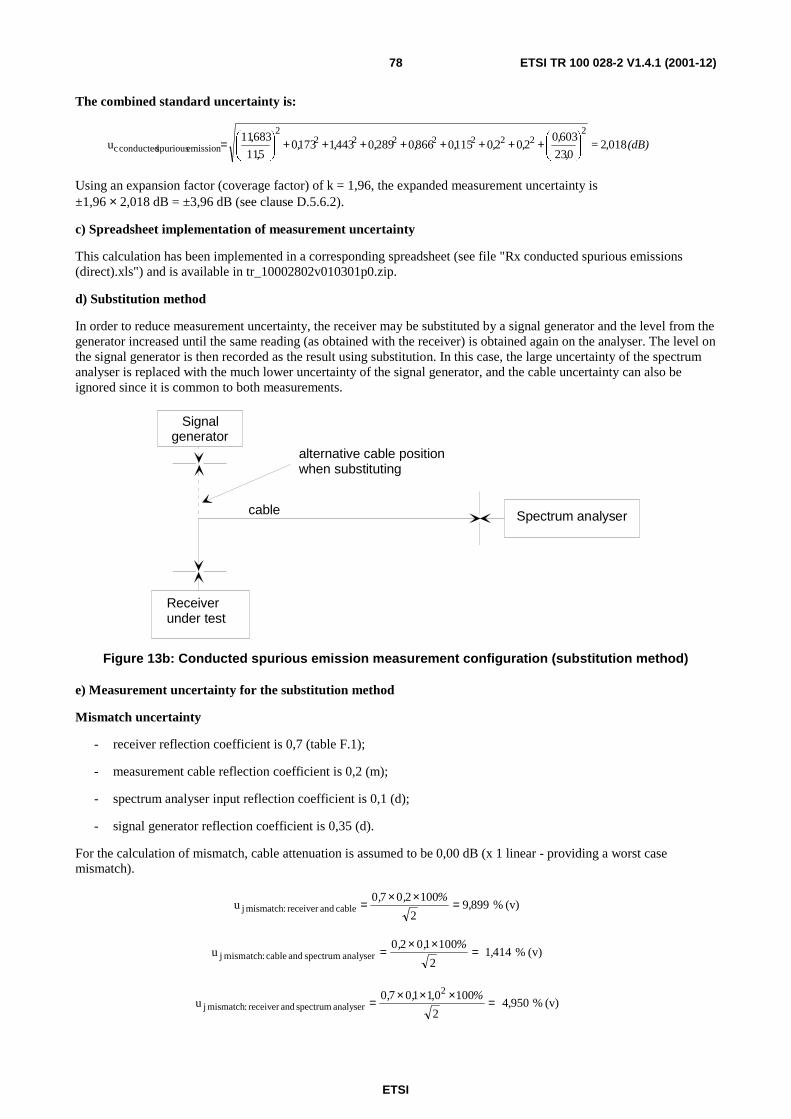
ETSI
ETSI TR 100 028-2 V1.4.1 (2001-12)78
The combined standard uncertainty is:
(dB) = ,
,,,,,,,,
,018,2
023
6030202011508660289044311730
511
683,11u
22222222
2
emission spurious conducted c
++++++++
=
Using an expansion factor (coverage factor) of k = 1,96, the expanded measurement uncertainty is ±1,96 × 2,018 dB = ±3,96 dB (see clause D.5.6.2).
c) Spreadsheet implementation of measurement uncertainty
This calculation has been implemented in a corresponding spreadsheet (see file "Rx conducted spurious emissions (direct).xls") and is available in tr_10002802v010301p0.zip.
d) Substitution method
In order to reduce measurement uncertainty, the receiver may be substituted by a signal generator and the level from the generator increased until the same reading (as obtained with the receiver) is obtained again on the analyser. The level on the signal generator is then recorded as the result using substitution. In this case, the large uncertainty of the spectrum analyser is replaced with the much lower uncertainty of the signal generator, and the cable uncertainty can also be ignored since it is common to both measurements.
cable
alternative cable positionwhen substituting
Spectrum analyser
Signalgenerator
Receiverunder test
Figure 13b: Conducted spurious emission measurement configuration (substitution method)
e) Measurement uncertainty for the substitution method
Mismatch uncertainty
- receiver reflection coefficient is 0,7 (table F.1);
- measurement cable reflection coefficient is 0,2 (m);
- spectrum analyser input reflection coefficient is 0,1 (d);
- signal generator reflection coefficient is 0,35 (d).
For the calculation of mismatch, cable attenuation is assumed to be 0,00 dB (x 1 linear - providing a worst case mismatch).
(v) %899,92
1002070u cable andreceiver :mismatch j
%,, =××=
(v) %41412
1001020u analyser spectrum and cable :mismatch j ,
%,,=
××=
(v) %950,42
1000,11070u
2
analyser spectrum andreceiver :mismatch j %,, =×××=

ETSI
ETSI TR 100 028-2 V1.4.1 (2001-12)79
(v) %95042
10020350u cable andgenerator :mismatch j ,
%,,=
××=
(v) %475,22
1000,110350u
2
analyserspectrum andgenerator :mismatch j %,, =×××=
The combined standard uncertainty for mismatch is:
(v) %455,12475,2950,4950,44141899,9u 22222mismatch c , =++++=
Uncertainty when making the measurement:
Signal generator (substitution signal) uncertainty ±1,5 dB (d):
dB, ,
u eneratorj Signal g 86603
51 ==
Random uncertainty:
Random uncertainty is 0,2 dB (m)(σ).
Uncertainty due to supply voltage:
Supply voltage uncertainty is ±100 mV (r).
Supply voltage uncertainty must be converted to an RF level uncertainty by means of formula 5.2 (see TR 100 028-1 [6]) and table F.1. Dependency values found in table F.1 are:
- mean value of 10 % (p)/V;
- standard deviation of 3 % (p)/V.
Therefore:
( ) ( ) ( )( ) )(+×
)( % 0,603 = V / % 0,3V / % 10,0
3
V 1,0u 22
2
voltagesupplyconverted j σp =
The combined standard uncertainty is:
dB = ,
,
, = 401,1
023
60302,0866,0
511
455,12u
222
2
emission spurious conducted c
+++
Using an expansion factor (coverage factor) of k = 1,96, the expanded measurement uncertainty is ±1,96 × 1,401 dB = ±2,75 dB (see clause D.5.6.2).
NOTE 2: The substitution example has a far lower measurement uncertainty than the direct example.
4.1.8 Amplitude characteristic for analogue speech
a) Methodology
The receiver under test is connected to a signal generator via a cable. The output from the receiver is connected to an AF voltmeter and load. The signal generator is adjusted to produce an appropriate level (usually near the threshold of limiting) and a reading on the AF voltmeter obtained. The signal generator is then adjusted to produce a considerably higher level and a second reading on the AF voltmeter obtained. The amplitude characteristic is recorded as the ratio (in dBs) between the two readings.

ETSI
ETSI TR 100 028-2 V1.4.1 (2001-12)80
ModulatingAF oscillator
Signalgenerator
Receiverundertest
AFload
AFVoltmeter
cable
Figure 14: Amplitude characteristic measurement configuration
Uncertainty contributions affecting RF input level must be included for the first measurement (combined and converted to AF level uncertainty by an appropriate dependency function) because at low RF levels below limiting, a small change in receiver RF input level may result in a relatively large change in AF output. In the second measurement (well above limiting) the resulting change at in AF output will usually be relatively small and the uncertainty of the RF input signal therefore considered negligible.
b) Measurement uncertainty
Mismatch uncertainty:
- signal generator reflection coefficient is 0,2 (d);
- receiver reflection coefficient (see table F.1) is 0,2;
- cable reflection coefficients are 0,1 (d).
In the calculation of mismatch uncertainty the cable attenuation is assumed to be 0,0 dB (x 1 linear).
(v) %41412
1001020u cable andgenerator :mismatch j ,
%,, =××=
(v) % 41412
1002010u receiver and cable :mismatch j ,
%,, =××=
(v) %82822
10012020u
2
receiver andgenerator :mismatch j ,%,, =×××=
The combined standard uncertainty is:
(v) %4643828,2414,1414,1u 222:mismatch c ,=++=
AF level uncertainty:
Signal generator level uncertainty 1 dB (d)(r):
dB,,
57703
01u levelgenerator signal j =±=
Uncertainty of the cable attenuation is 0,1 dB (m)(σ).
The combined standard uncertainty for the level is:
dB659,01,0577,05,11
464,3u 22
2
:level c =++
=

ETSI
ETSI TR 100 028-2 V1.4.1 (2001-12)81
RF level uncertainty is converted to AF level uncertainty by means of formula 5.2 (of TR 100 028-1 [6]) and table F.1. Dependency values found in table F.1 are:
- mean value is 0,05 %/%;
- standard deviation is 0,02 %/% level.
Dependency values must be converted from percentage to dBs using table 1 in clause 5.2 of TR 100 028-1 [6]. Since like units are involved (i.e. % per %), the dependency values can be considered as:
- mean value of 0,05 dB/dB;
- standard deviation of 0,02 dB/dB level.
Therefore:
( ) ( )( ) dB,= dB / dB, dB / dB,dB, 03500200506590u 222level AF j +×=
In the first measurement there may be some variation in the AF voltmeter reading due to noise.
Noise variation at low RF level is 0,2 dB (m)(σ).
In the second measurement the AF level is well above the system noise floor and the variation therefore negligible.
AF volt meter uncertainty is ±0,2 dB (d) (r) (Must be allowed for twice):
dB 0,115 3
0,2u meter voltj ==
The combined standard uncertainty for amplitude characteristic is:
dB, ,,,, 260011501150200350u 2222sticcharacteri amplitude c =+++=
Using an expansion factor (coverage factor) of k = 1,96, the expanded measurement uncertainty is ±1,96 × 0,260 dB = ±0,51 dB (see TR 100 028-1 [6], clause D.5.6.2).
c) Spreadsheet implementation of measurement uncertainty
This calculation has been implemented in a corresponding spreadsheet (see file "Amplitude characteristic.xls") and is available in tr_10002802v010301p0.zip.
4.1.9 Audio frequency response for analogue speech
Example not provided.
4.1.10 Harmonic distortion for analogue speech
Example not provided.
4.1.11 Hum and noise for analogue speech
Example not provided.
4.1.12 Multi-path sensitivity
Example not provided.
4.1.13 Bit error ratio
Example not provided.

ETSI
ETSI TR 100 028-2 V1.4.1 (2001-12)82
4.1.14 Opening delay for data
Example not provided.
4.2 Radiated
4.2.1 Sensitivity tests (30 MHz to 1 000 MHz)
A fully worked example illustrating the methodology to be used can be found in TR 102 273 [2], part 1, clause 11.
4.2.1.1 Anechoic Chamber
For receiver sensitivity measurement two stages of test are involved.
4.2.1.1.1 Uncertainty contributions: Stage one: Determination of Transform Factor
The first stage (determining the Transform Factor) involves placing a measuring antenna as shown in figure 15 and determining the relationship between the signal generator output power level and the resulting field strength (the shaded areas in figure 15 represent components common to both stages of the test).
Testantennacable 2
ferrite beads
Test antenna
Signalgenerator
Attenuator 210 dB
Measuring antenna
Measuringantennacable 1
Receiving device
Attenuator 110 dB
Figure 15: Stage 1: Transform Factor
All the uncertainty components which contribute to this stage of the test are listed in table 1. Annex A should be consulted for the sources and/or magnitudes of the uncertainty contributions.

ETSI
ETSI TR 100 028-2 V1.4.1 (2001-12)83
Table 1: Contributions for the transform factor
uj or i Description of uncertainty contributions dB
uj36 mismatch: transmitting part 0,00
uj37 mismatch: receiving part
uj38 signal generator: absolute output level
uj39 signal generator: output level stability
uj19 cable factor: measuring antenna cable
uj19 cable factor: test antenna cable 0,00
uj41 insertion loss: measuring antenna cable
uj41 insertion loss: test antenna cable 0,00
uj40 insertion loss: measuring antenna attenuator
uj40 insertion loss: test antenna attenuator 0,00
uj47 receiving device: absolute level
uj16 range length 0,00
uj02 reflectivity of absorber material: measuring antenna to the test antenna 0,00
uj44 antenna: antenna factor of the measuring antenna
uj45 antenna: gain of the test antenna 0,00
uj46 antenna: tuning of the measuring antenna
uj46 antenna: tuning of the test antenna 0,00
uj22 position of the phase centre: measuring antenna
uj06 mutual coupling: measuring antenna to its images in the absorbing material
uj06 mutual coupling: test antenna to its images in the absorbing material 0,00
uj11 mutual coupling: measuring antenna to the test antenna 0,00
uj12 mutual coupling: interpolation of mutual coupling and mismatch loss correction factors 0,00
ui01 random uncertainty
The standard uncertainties from table 1 should be combined by RSS in accordance with TR 102 273 [2], part 1, sub-part 1, clause 5. This gives the combined standard uncertainty (uc contributions from the Transform Factor) for the Transform Factor in dB.
4.2.1.1.2 Uncertainty contributions: Stage two: EUT measurement
The second stage (the EUT measurement) is to determine the minimum signal generator output level which produces the required response from the EUT as shown in figure 16 (the shaded areas represent components common to both stages of the test).
Testantennacable 2
ferrite beads
Test antenna
Signalgenerator
Attenuator 210 dBEUT
Figure 16: Stage 2: EUT measurement
All the uncertainty components which contribute to this stage of the test are listed in table 2. Annex A should be consulted for the sources and/or magnitudes of the uncertainty contributions.

ETSI
ETSI TR 100 028-2 V1.4.1 (2001-12)84
Table 2: Contributions from the EUT measurement
uj or i Description of uncertainty contributions dB uj36 mismatch: transmitting part
uj37 mismatch: receiving part
uj38 signal generator: absolute output level
uj39 signal generator: output level stability
uj19 cable factor: test antenna cable 0,00
uj41 insertion loss: test antenna cable 0,00
uj40 insertion loss: test antenna attenuator 0,00
uj20 position of the phase centre: within the EUT volume
uj22 positioning of the phase centre: within the EUT over the axis of rotation of the turntable
uj52 EUT: modulation detection
uj16 range length 0,00
uj01 reflectivity of absorber material: EUT to the test antenna
uj45 antenna: gain of the test antenna 0,00
uj46 antenna: tuning of the test antenna 0,00
uj55 EUT: mutual coupling to the power leads
uj08 mutual coupling: amplitude effect of the test antenna on the EUT 0,00
uj04 mutual coupling: EUT to its images in the absorbing materials
uj06 mutual coupling: test antenna to its images in the absorbing material 0,00
ui01 random uncertainty
The standard uncertainties from table 2 should be combined by RSS in accordance with TR 102 273 [2], part 1, sub-part 1, clause 5. This gives the combined standard uncertainty (uc contribution from the EUT measurement) for the EUT
measurement in dB.
4.2.1.1.3 Expanded uncertainty of the receiver sensitivity measurement
The combined uncertainty of the sensitivity measurement is the combination of the components outlined in clauses 4.2.1.1.1 and 4.2.1.1.2. The components to be combined are uc contribution from the Transform Factor and
uc contribution from the EUT measurement:
u u uc c contribution fromthe Transform Factor c contribution fromthe EUT measurement= +2 2 = _ _ ,_ _ dB
Using an expansion factor (coverage factor) of k = 1,96, the expanded measurement uncertainty is ±1,96 × uc = ±__,__ dB (see clause D.5.6.2).
4.2.1.2 Anechoic Chamber with a ground plane
A fully worked example illustrating the methodology to be used can be found in TR 102 273 [2], part 1, sub-part 2, clause 4.
4.2.1.2.1 Uncertainty contributions: Stage one: Determination of Transform Factor
The first stage (determining the Transform Factor) involves placing a measuring antenna as shown in figure 17 and determining the relationship between the signal generator output power level and the resulting field strength (the shaded areas in figure 17 represent components common to both stages of the test).

ETSI
ETSI TR 100 028-2 V1.4.1 (2001-12)85
Measuring antenna
Measuringantennacable 1
Receiving device
Testantennacable 2
ferrite beads
Signalgenerator
Attenuator 210 dB
Test antenna
Attenuator 110 dB
Ground plane
Figure 17: Stage one: Determination of Transform Factor
All the uncertainty components which contribute to this stage of the test are listed in table 3. Annex A should be consulted for the sources and/or magnitudes of the uncertainty contributions.
Table 3: Contributions for the Transform Factor
uj or i Description of uncertainty contributions dB uj36 mismatch: transmitting part
uj37 mismatch: receiving part
uj38 signal generator: absolute output level 0,00
uj39 signal generator: output level stability
uj19 cable factor: measuring antenna cable
uj19 cable factor: test antenna cable
uj41 insertion loss: measuring antenna cable
uj41 insertion loss: test antenna cable 0,00
uj40 insertion loss: measuring antenna attenuator
uj40 insertion loss: test antenna attenuator 0,00
uj47 receiving device: absolute level
uj16 range length
uj02 reflectivity of absorbing material: measuring antenna to the test antenna
uj44 antenna: antenna factor of the measuring antenna
uj45 antenna: gain of the test antenna
uj46 antenna: tuning of the measuring antenna
uj46 antenna: tuning of the test antenna 0,00
uj22 position of the phase centre: measuring antenna
uj06 mutual coupling: measuring antenna to its images in the absorbing material
uj06 mutual coupling: test antenna to its images in the absorbing material
uj14 mutual coupling: measuring antenna to its images in the ground plane
uj14 mutual coupling: test antenna to its images in the ground plane
uj11 mutual coupling: measuring antenna to the test antenna
uj12 mutual coupling: interpolation of mutual coupling and mismatch loss correction factors
ui01 random uncertainty
The standard uncertainties from table 18 should be combined by RSS in accordance with TR 102 273 [2], part 1, sub-part 1, clause 5. This gives the combined standard uncertainty (uc contributions from the Transform Factor) for the
Transform Factor in dB.

ETSI
ETSI TR 100 028-2 V1.4.1 (2001-12)86
4.2.1.2.2 Uncertainty contributions: Stage two: EUT measurement
The second stage (the EUT measurement) is to determine the minimum signal generator output level which produces the required response from the EUT as shown in figure 18 (the shaded areas represent components common to both stages of the test).
Testantennacable 2
ferrite beads
Test antenna
SignalEUT Attenuator 2
10 dB generator
Ground plane
Figure 18: Stage 2: EUT measurement
All the uncertainty components which contribute to this stage of the test are listed in table 4. Annex A should be consulted for the sources and/or magnitudes of the uncertainty contributions.
Table 4: Contributions from the EUT measurement
uj or i Description of uncertainty contributions dB uj36 mismatch: transmitting part
uj38 signal generator: absolute output level 0,00
uj39 signal generator: output level stability
uj19 cable factor: test antenna cable
uj41 insertion loss: test antenna cable 0,00
uj40 insertion loss: test antenna attenuator 0,00
uj20 position of the phase centre: within the EUT volume
uj21 positioning of the phase centre: within the EUT over the axis of rotation of the turntable
uj52 EUT: modulation detection
uj16 range length
uj01 reflectivity of absorbing material: EUT to the test antenna
uj45 antenna: gain of the test antenna 0,00
uj46 antenna: tuning of the test antenna 0,00
uj55 EUT: mutual coupling to the power leads
uj08 mutual coupling: amplitude effect of the test antenna on the EUT
uj04 mutual coupling: EUT to its images in the absorbing materials
uj13 mutual coupling: EUT to its image in the ground plane
uj06 mutual coupling: test antenna to its images in the absorbing material
uj14 mutual coupling: test antenna to its image in the ground plane
ui01 random uncertainty
The standard uncertainties from table 4 should be combined by RSS in accordance with TR 102 273 [2], part 1, sub-part 1, clause 5. This gives the combined standard uncertainty (uc contribution from the EUT measurement) for the EUT measurement in dB.

ETSI
ETSI TR 100 028-2 V1.4.1 (2001-12)87
4.2.1.2.3 Expanded uncertainty of the receiver sensitivity measurement
The combined uncertainty of the sensitivity measurement is the combination of the components outlined in clauses 4.2.1.2.1 and 4.2.1.2.2. The components to be combined are uc contribution from the Transform Factor and
uc contribution from the EUT measurement:
u u uc c contribution fromthe Transform factor c contribution fromthe EUT measurement= +2 2 = _ _ ,_ _ dB
Using an expansion factor (coverage factor) of k = 1,96, the expanded measurement uncertainty is ±1,96 × uc = ±__,__ dB (see clause D.5.6.2).
4.2.1.3 Open Area Test Site
A fully worked example illustrating the methodology to be used can be found in TR 102 273 [2], part 1, sub-part 2, clause 4. For receiver sensitivity measurement two stages of test are involved.
4.2.1.3.1 Uncertainty contributions: Stage one: Transform Factor
The first stage (determining the Transform Factor) involves placing a measuring antenna as shown in figure 19 and determining the relationship between the signal generator output power level and the resulting field strength (the shaded areas in figure 19 represent components common to both stages of the test).
Measuring antenna
Measuringantennacable 1
Receiving device
Testantennacable 2
ferrite beads
SignalAttenuator 210 dB
Test antenna
Attenuator 110 dB generator
Ground plane
Figure 19: Stage 1: Transform Factor
All the uncertainty components which contribute to this stage of the test are listed in table 5.

ETSI
ETSI TR 100 028-2 V1.4.1 (2001-12)88
Table 5: Contributions for the Transform Factor
uj or i Description of uncertainty contributions dB uj36 mismatch: transmitting part
uj37 mismatch: receiving part
uj38 signal generator: absolute output level 0,00
uj39 signal generator: output level stability
uj19 cable factor: measuring antenna cable
uj19 cable factor: test antenna cable
uj41 insertion loss: measuring antenna cable
uj41 insertion loss: test antenna cable 0,00
uj40 insertion loss: measuring antenna attenuator
uj40 insertion loss: test antenna attenuator 0,00
uj47 receiving device: absolute level
uj16 range length
uj44 antenna: antenna factor of the measuring antenna
uj45 antenna: gain of the test antenna
uj46 antenna: tuning of the measuring antenna
uj46 antenna: tuning of the test antenna 0,00
uj22 position of the phase centre: measuring antenna
uj14 mutual coupling: measuring antenna to its images in the ground plane
uj14 mutual coupling: test antenna to its images in the ground plane
uj11 mutual coupling: measuring antenna to the test antenna
uj12 mutual coupling: interpolation of mutual coupling and mismatch loss correction factors
ui01 random uncertainty
The standard uncertainties from table 5 should be combined by RSS in accordance with TR 102 273 [2], part 1, sub-part 1, clause 5. This gives the combined standard uncertainty (uc contributions from the Transform Factor) for the Transform Factor in dB.
4.2.1.3.2 Uncertainty contributions: Stage two: EUT measurement
The second stage (the EUT measurement) is to determine the minimum signal generator output level which produces the required response from the EUT as shown in figure 20 (the shaded areas represent components common to both stages of the test).
Testantennacable 2
ferrite beads
Test antenna
SignalEUT Attenuator 2
10 dB
Ground plane
generator
Figure 20: Stage 2: EUT measurement
All the uncertainty components which contribute to this stage of the test are listed in table 6. Annex A should be consulted for the sources and/or magnitudes of the uncertainty contributions.

ETSI
ETSI TR 100 028-2 V1.4.1 (2001-12)89
Table 6: Contributions from the EUT measurement
uj or i Description of uncertainty contributions dB uj36 mismatch: transmitting part
uj38 signal generator: absolute output level 0,00
uj39 signal generator: output level stability
uj19 cable factor: test antenna cable
uj41 insertion loss: test antenna cable 0,00
uj40 insertion loss: test antenna attenuator 0,00
uj20 position of the phase centre: within the EUT volume
uj21 positioning of the phase centre: within the EUT over of the axis of rotation of the turntable
uj52 EUT: modulation detection
uj16 range length
uj45 antenna: gain of the test antenna 0,00
uj46 antenna: tuning of the test antenna 0,00
uj55 EUT: mutual coupling to the power leads
uj08 mutual coupling: amplitude effect of the test antenna on the EUT
uj13 mutual coupling: EUT to its image in the ground plane
uj14 mutual coupling: test antenna to its image in the ground plane
ui01 random uncertainty
The standard uncertainties from table 6 should be combined by RSS in accordance with TR 102 273 [2], part 1, sub-part 1, clause 5. This gives the combined standard uncertainty (uc contribution from the EUT measurement) for the EUT measurement in dB.
4.2.1.3.3 Expanded uncertainty of the receiver sensitivity measurement
The combined uncertainty of the sensitivity measurement is the combination of the components outlined in clauses 4.2.1.3.1 and 4.2.1.3.2. The components to be combined are uc contribution from the Transform Factor and uc contribution
from the EUT measurement:
u u uc c contribution fromthe Transform factor c contribution fromthe EUT measurement= +2 2 = _ _ ,_ _ dB
Using an expansion factor (coverage factor) of k = 1,96, the expanded measurement uncertainty is ±1,96 × uc = ±__,__ dB (see clause D.5.6.2).
4.2.1.4 Striplines
For tests in which the results of the verification procedure have been used, the test will have comprised only a single measurement stage. Otherwise, two measurement stages of the test would have been involved.
A fully worked example calculation can be found in TR 102 273 [2], part 1, sub-part 2, clause 5.
4.2.1.4.1 Uncertainty contributions: Stage 1: EUT measurement
The first stage involves the measurement set-up as shown in figure 21.

ETSI
ETSI TR 100 028-2 V1.4.1 (2001-12)90
150termination
Load
Central axisof stripline
Signal
Ferrite beads 10dBattenuator
Non-conducting,low dielectric constantsupport stand
EUT with volume centre midway between plates
Modulation
ΩΩΩΩ
generator
detection
Figure 21: Stage 1 schematic: EUT Measurement
Table 7 lists the uncertainty contributions involved in this stage of the test. Annex A should be consulted for the sources and/or magnitudes of the uncertainty contributions.
Table 7: Uncertainty contributions from the EUT measurement
uj or i Description of uncertainty contributions dB uj36 mismatch: transmitting part
uj37 mismatch: receiving part
uj38 signal generator: absolute output level
uj39 signal generator: output level stability
uj19 cable factor: signal generator 0,00
uj41 insertion loss: signal generator cable 0,00
uj40 insertion loss: signal generator attenuator 0,00
uj47 receiving device: absolute level 0,00
uj48 receiving device: linearity 0,00
uj32 Stripline: correction factor for the size of the EUT
uj24 Stripline: mutual coupling of the EUT to its images in the plates
uj55 EUT: mutual coupling to the power leads
uj26 Stripline: characteristic impedance
uj27 Stripline: non-planar nature of the field distribution
uj33 Stripline: influence of site effects
uj34 ambient effect
uj52 EUT: modulation detection
ui01 random uncertainty
The standard uncertainties from table 7 should be combined by RSS in accordance with TR 102 273 [2], part 1, sub-part 1, clause 5. This gives the combined standard uncertainty, uc EUT measurement, for the EUT measurement in dB.
4.2.1.4.2 Uncertainty contributions: Stage 2: Field measurement
For tests using the results of the verification procedure
As stated above, for tests in which the results of the verification procedure are used, this second stage does not really exist. In terms of its contribution to the overall uncertainty of this test, the verification procedure contributes the full value of its overall uncertainty. So, in this case, the standard deviation of the verification procedure is taken as the contribution uc field measurement.
For the Monopole
Figure 22 shows schematically the equipment set-up for this stage of the test. The uncertainty contributions resulting are given in table 23. Annex A should be consulted for the sources and/or magnitudes of the uncertainty contributions.

ETSI
ETSI TR 100 028-2 V1.4.1 (2001-12)91
150termination
Load
Central axis of Stripline
Signal
Ferrite beads 10dBattenuators
Monopole
Receiving
ΩΩΩΩ
generator
device
Figure 22: Stage 2 schematic: Monopole field measurement
Table 8: Uncertainty contributions from the Monopole field measurement
uj or i Description of uncertainty contributions dB uj36 mismatch: transmitting part
uj37 mismatch: receiving part
uj47 signal generator: absolute output level
uj48 signal generator: output level stability
uj19 cable factor: signal generator 0,00
uj19 cable factor: monopole cable 0,00
uj41 insertion loss: signal generator cable 0,00
uj41 insertion loss: monopole cable 0,00
uj40 insertion loss: signal generator attenuator 0,00
uj40 insertion loss: monopole attenuator 0,00
uj47 receiving device: absolute level 0,00
uj48 receiving device: linearity 0,00
uj31 Stripline: antenna factor of the monopole
uj32 Stripline: correction factor for the size of the EUT
uj24 Stripline: mutual coupling of the EUT to its images in the plates
uj26 Stripline: characteristic impedance
uj27 Stripline: non-planar nature of the field distribution
uj33 Stripline: influence of site effects
uj34 ambient effect
ui01 random uncertainty
The standard uncertainties from table 8 should be combined by RSS in accordance with TR 102 273 [2], part 1, sub-part 1, clause 5. This gives the combined standard uncertainty, uc field measurement, for the Monopole field measurement in dB.
For the 3-axis probe
The uncertainty contributions for this configuration during the test are as given in table 9. Annex A should be consulted for the sources and/or magnitudes of the uncertainty contributions.

ETSI
ETSI TR 100 028-2 V1.4.1 (2001-12)92
Table 9: Uncertainty contributions from the field measurement
uj or i Description of uncertainty contributions dB uj36 mismatch: transmitting part
uj38 signal generator: absolute output level
uj39 signal generator: output level stability
uj19 cable factor: signal generator 0,00
uj41 insertion loss: signal generator cable 0,00
uj40 insertion loss: signal generator attenuator 0,00
uj28 Stripline: field strength measurement as determined by the 3-axis probe
uj32 Stripline: correction factor for the size of the EUT
uj24 Stripline: mutual coupling of the EUT to its images in the plates
uj26 Stripline: characteristic impedance
uj27 Stripline: non-planar nature of the field distribution
uj33 Stripline: influence of site effects
uj34 ambient effect
uj25 Stripline: mutual coupling of the 3-axis probe to its image in the plates
ui01 random uncertainty
The standard uncertainties from table 9 should be combined by RSS in accordance with TR 102 273 [2], part 1, sub-part 1, clause 5. This gives the combined standard uncertainty, uc field measurement, for the 3-axis probe field measurement in dB.
4.2.1.4.3 Expanded uncertainty for the Receiver sensitivity measurement
The combined standard uncertainty of the results of the receiver sensitivity measurement is the RSS combination of the components outlined in clauses 4.2.1.4.1 and 4.2.4.1.2 above. The components to be combined are uc EUT measurement and uc field measurement.
u = u + u = __,__c c EUT measurement c field measurement dB2 2
Using an expansion factor (coverage factor) of k = 1,96, the expanded measurement uncertainty is ±1,96 × uc = ±__,__ dB (see clause D.5.6.2).
4.2.1.5 Test Fixture
Tests in a test fixture differ to radiated tests on all other types of site in that there is only one stage to the test. All uncertainty contributions for the test can, therefore, be incorporated into one table and these are given in table 10.
4.2.1.5.1 Uncertainty contributions
All the uncertainty contributions for the test are listed in table 10.
Table 10: Contributions from the measurement
uj or i Description of uncertainty contributions dB uj38 signal generator: absolute output level
uj39 signal generator: output level stability
uj60 Test Fixture: effect on the EUT
uj61 Test Fixture: climatic facility effect on the EUT
ui01 random uncertainty

ETSI
ETSI TR 100 028-2 V1.4.1 (2001-12)93
The standard uncertainties from table 10 should be given values according to annex A. They should then be combined by RSS in accordance with TR 102 273 [2], part 1, sub-part 1, clause 5. This gives the combined standard uncertainty (uc contributions from the measurement) for the EUT measurement in dB.
4.2.1.5.2 Expanded uncertainty of the Maximum usable sensitivity measurement
Tests in a Test Fixture differ to radiated tests on all other types of site in that there is only one stage to the test. However, the Test Fixture measurement could be considered as stage two of a test in which stage one was on an accredited Free-Field Test Site. The combined standard uncertainty of the maximum usable sensitivity measurement is therefore, simply the RSS combination of the value for uc contributions from the measurement derived above and the combined
uncertainty of the Free-Field Test Site uc contribution from the Free-Field Test Site.
dB____,2
2 =+= sitetestfieldfreethefromonscontributictmeasurementhefromonscontributicc uuu
Using an expansion factor (coverage factor) of k = 1,96, the expanded measurement uncertainty is ±1,96 × uc = ±__,__ dB (see clause D.5.6.2).
4.2.1.6 Salty Man/Salty lite
4.2.1.6.1 Anechoic Chamber
A fully worked example illustrating the methodology to be used can be found in TR 102 273 [2], part 1, sub-part 2, clause 4.
The receiver sensitivity measurement involves two stages of testing.
4.2.1.6.1.1 Uncertainty contributions: Stage one: Transform factor measurement
The first stage (determining the Transform Factor) involves placing a measuring antenna as shown in figure 23 and determining the relationship between the signal generator output power level and the resulting field strength (the shaded areas in figure 23 represent components common to both stages of the test).
Testantennacable 2
ferrite beads
Test antenna
Attenuator 210 dB
Measuring antenna
Measuringantennacable 1
Receiving device
Attenuator 110 dB
Signalgenerator
Figure 23: Stage 1: Transform Factor
All the uncertainty components which contribute to this stage of the test are listed in table 11. Annex A should be consulted for the sources and/or magnitudes of the uncertainty contributions.

ETSI
ETSI TR 100 028-2 V1.4.1 (2001-12)94
Table 11: Contributions for the Transform Factor
uj or i Description of uncertainty contributions dB uj36 mismatch: transmitting part 0,00
uj37 mismatch: receiving part
uj38 signal generator: absolute output level
uj39 signal generator: output level stability
uj19 cable factor: measuring antenna cable
uj19 cable factor: test antenna cable 0,00
uj41 insertion loss: measuring antenna cable
uj41 insertion loss: test antenna cable 0,00
uj40 insertion loss: measuring antenna attenuator
uj40 insertion loss: test antenna attenuator 0,00
uj47 receiving device: absolute level
uj16 range length 0,00
uj02 reflectivity of absorber material: measuring antenna to the test antenna 0,00
uj44 antenna: antenna factor of the measuring antenna
uj45 antenna: gain of the test antenna 0,00
uj46 antenna: tuning of the measuring antenna
uj46 antenna: tuning of the test antenna 0,00
uj22 position of the phase centre: measuring antenna
uj06 mutual coupling: measuring antenna to its images in the absorbing material
uj06 mutual coupling: test antenna to its images in the absorbing material 0,00
uj11 mutual coupling: measuring antenna to the test antenna 0,00
uj12 mutual coupling: interpolation of mutual coupling and mismatch loss correction factors 0,00
ui01 random uncertainty
The standard uncertainties from table 11 should be combined by RSS in accordance with TR 102 273 [2], part 1, sub-part 1, clause 5. This gives the combined standard uncertainty (uc contributions from the Transform Factor) for the Transform Factor in dB.
4.2.1.6.1.2 Uncertainty contributions: Stage two: EUT measurement
The second stage (the EUT measurement) is to determine the minimum signal generator output level which produces the required response from the EUT as shown in figure 24 (the shaded areas represent components common to both stages of the test).
Testantennacable 2
ferrite beads
Test antenna
SignalAttenuator 210 dB
EUT generator
Figure 24: Stage 2: EUT measurement
All the uncertainty components which contribute to this stage of the test are listed in table 12. Annex A should be consulted for the sources and/or magnitudes of the uncertainty contributions.

ETSI
ETSI TR 100 028-2 V1.4.1 (2001-12)95
Table 12: Contributions from the EUT measurement
uj or i Description of uncertainty contributions dB uj36 mismatch: transmitting part 0,00
uj37 mismatch: receiving part
uj38 signal generator: absolute output level
uj39 signal generator: output level stability
uj19 cable factor: measuring antenna cable
uj19 cable factor: test antenna cable 0,00
uj41 insertion loss: measuring antenna cable
uj41 insertion loss: test antenna cable 0,00
uj40 insertion loss: measuring antenna attenuator
uj40 insertion loss: test antenna attenuator 0,00
uj47 receiving device: absolute level
uj16 range length 0,00
uj02 reflectivity of absorber material: measuring antenna to the test antenna 0,00
uj44 antenna: antenna factor of the measuring antenna
uj45 antenna: gain of the test antenna 0,00
uj46 antenna: tuning of the measuring antenna
uj46 antenna: tuning of the test antenna 0,00
uj22 position of the phase centre: measuring antenna
uj06 mutual coupling: measuring antenna to its images in the absorbing material
uj06 mutual coupling: test antenna to its images in the absorbing material 0,00
uj11 mutual coupling: measuring antenna to the test antenna 0,00
uj12 mutual coupling: interpolation of mutual coupling and mismatch loss correction factors 0,00
uj58 Salty man/salty-lite: human simulation
uj59 Salty man/salty-lite: field enhancement and de-tuning of the EUT
ui01 random uncertainty
The standard uncertainties from table 13 should be combined by RSS in accordance with TR 102 273 [2], part 1, sub-part 1, clause 5. This gives the combined standard uncertainty (uc contribution from the EUT measurement) for the EUT
measurement in dB.
4.2.1.6.1.3 Expanded uncertainty
The combined uncertainty of the sensitivity measurement is the combination of the components outlined in clauses 4.2.1.6.1.1 and 4.2.1.6.1.2. The components to be combined are uc contribution from the Transform Factor and
uc contribution from the EUT measurement.
u u uc ccontribution fromtheTransform Factor ccontribution fromthe EUT measurement= +2 2 = _ _ , _ _ dB
Using an expansion factor (coverage factor) of k = 1,96, the expanded measurement uncertainty is ±1,96 × uc = ±__,__ dB (see clause D.5.6.2).
4.2.1.6.2 Anechoic Chamber with a ground plane
A fully worked example illustrating the methodology to be used can be found in TR 102 273 [2], part 1, sub-part 2, clause 4.
The receiver sensitivity measurement involves two stages of testing.

ETSI
ETSI TR 100 028-2 V1.4.1 (2001-12)96
4.2.1.6.2.1 Uncertainty contributions: Stage one: Determination of Transfer Factor
The first stage (determining the Transform Factor) involves placing a measuring antenna as shown in figure 25 and determining the relationship between the signal generator output power level and the resulting field strength (the shaded areas in figure 25 represent components common to both stages of the test).
Measuring antenna
Measuringantennacable 1
Receiving device
Testantennacable 2
ferrite beads
SignalAttenuator 210 dB
Test antenna
Attenuator 110 dB generator
Ground plane
Figure 25: Stage 1: Transform Factor
All the uncertainty components which contribute to this stage of the test are listed in table 13. Annex A should be consulted for the sources and/or magnitudes of the uncertainty contributions.
Table 13: Contributions for the Transform Factor
uj or i Description of uncertainty contributions dB uj36 mismatch: transmitting part
uj37 mismatch: receiving part
uj38 signal generator: absolute output level 0,00
uj39 signal generator: output level stability
uj19 cable factor: measuring antenna cable
uj19 cable factor: test antenna cable
uj41 insertion loss: measuring antenna cable
uj41 insertion loss: test antenna cable 0,00
uj40 insertion loss: measuring antenna attenuator
uj40 insertion loss: test antenna attenuator 0,00
uj47 receiving device: absolute level
uj16 range length
uj02 reflectivity of absorbing material: measuring antenna to the test antenna
uj44 antenna: antenna factor of the measuring antenna
uj45 antenna: gain of the test antenna
uj46 antenna: tuning of the measuring antenna
uj46 antenna: tuning of the test antenna 0,00
uj22 position of the phase centre: measuring antenna
uj06 mutual coupling: measuring antenna to its images in the absorbing material
uj06 mutual coupling: test antenna to its images in the absorbing material
uj14 mutual coupling: measuring antenna to its images in the ground plane
uj14 mutual coupling: test antenna to its images in the ground plane
uj11 mutual coupling: measuring antenna to the test antenna
uj12 mutual coupling: interpolation of mutual coupling and mismatch loss correction factors
ui01 random uncertainty
The standard uncertainties from table 13 should be combined by RSS in accordance with TR 102 273 [2], part 1, sub-part 1, clause 5. This gives the combined standard uncertainty (uc contributions from the Transform Factor) for the
Transform Factor in dB.

ETSI
ETSI TR 100 028-2 V1.4.1 (2001-12)97
4.2.1.6.2.2 Uncertainty contributions: Stage two: EUT measurement
The second stage (the EUT measurement) is to determine the minimum signal generator output level which produces the required response from the EUT as shown in figure 26 (the shaded areas represent components common to both stages of the test).
Testantennacable 2
ferrite beads
Test antenna
SignalEUT Attenuator 210 dB generator
Ground plane
Figure 26: Stage 2: EUT measurement
All the uncertainty components which contribute to this stage of the test are listed in table 14. Annex A should be consulted for the sources and/or magnitudes of the uncertainty contributions.
Table 14: Contributions from the EUT measurement
uj or i Description of uncertainty contributions dB uj36 mismatch: transmitting part
uj38 signal generator: absolute output level 0,00
uj39 signal generator: output level stability
uj19 cable factor: test antenna cable
uj41 insertion loss: test antenna cable 0,00
uj40 insertion loss: test antenna attenuator 0,00
uj20 position of the phase centre: within the EUT volume
uj21 positioning of the phase centre: within the EUT over the axis of rotation of the turntable
uj52 EUT: modulation detection
uj16 range length
uj01 reflectivity of absorbing material: EUT to the test antenna
uj45 antenna: gain of the test antenna 0,00
uj46 antenna: tuning of the test antenna 0,00
uj55 EUT: mutual coupling to the power leads
uj08 mutual coupling: amplitude effect of the test antenna on the EUT
uj04 mutual coupling: EUT to its images in the absorbing materials
uj13 mutual coupling: EUT to its image in the ground plane
uj06 mutual coupling: test antenna to its images in the absorbing material
uj14 mutual coupling: test antenna to its image in the ground plane
uj58 Salty man/salty-lite: human simulation
uj59 Salty man/salty-lite: field enhancement and de-tuning of the EUT
ui01 random uncertainty
The standard uncertainties from table 14 should be combined by RSS in accordance with TR 102 273 [2], part 1, sub-part 1, clause 5. This gives the combined standard uncertainty (uc contribution from the EUT measurement) for the EUT measurement in dB.

ETSI
ETSI TR 100 028-2 V1.4.1 (2001-12)98
4.2.1.6.2.3 Expanded uncertainty
The combined uncertainty of the sensitivity measurement is the combination of the components outlined in clauses 4.2.1.6.2.1 and 4.2.1.6.2.2. The components to be combined are uc contribution from the Transform Factor and
uc contribution from the EUT measurement.
u u uc ccontribution fromtheTransform Factor ccontribution fromthe EUT measurement= +2 2 = _ _ , _ _ dB
Using an expansion factor (coverage factor) of k = 1,96, the expanded measurement uncertainty is ±1,96 × uc = ±__,__ dB (see clause D.5.6.2).
4.2.1.6.3 Open Area Test Site
A fully worked example illustrating the methodology to be used can be found in TR 102 273 [2], part 1, sub-part 2, clause 4.
The receiver sensitivity measurement involves two stages of testing.
4.2.1.6.3.1 Uncertainty contributions: Stage one: Transfer Factor
The first stage (determining the Transform Factor) involves placing a measuring antenna as shown in figure 27 and determining the relationship between the signal generator output power level and the resulting field strength (the shaded areas in figure 27 represent components common to both stages of the test).
Measuring antenna
Measuringantennacable 1
Receiving device
Testantennacable 2
ferrite beads
SignalAttenuator 210 dB
Test antenna
Attenuator 110 dB generator
Ground plane
Figure 27: Stage 1: Transform Factor
All the uncertainty components which contribute to this stage of the test are listed in table 15. Annex A should be consulted for the sources and/or magnitudes of the uncertainty contributions.

ETSI
ETSI TR 100 028-2 V1.4.1 (2001-12)99
Table 15: Contributions for the Transform Factor
uj or i Description of uncertainty contributions dB uj36 mismatch: transmitting part
uj37 mismatch: receiving part
uj38 signal generator: absolute output level 0,00
uj39 signal generator: output level stability
uj19 cable factor: measuring antenna cable
uj19 cable factor: test antenna cable
uj41 insertion loss: measuring antenna cable
uj41 insertion loss: test antenna cable 0,00
uj40 insertion loss: measuring antenna attenuator
uj40 insertion loss: test antenna attenuator 0,00
uj47 receiving device: absolute level
uj16 range length
uj44 antenna: antenna factor of the measuring antenna
uj45 antenna: gain of the test antenna
uj46 antenna: tuning of the measuring antenna
uj46 antenna: tuning of the test antenna 0,00
uj22 position of the phase centre: measuring antenna
uj14 mutual coupling: measuring antenna to its images in the ground plane
uj14 mutual coupling: test antenna to its images in the ground plane
uj11 mutual coupling: measuring antenna to the test antenna
uj12 mutual coupling: interpolation of mutual coupling and mismatch loss correction factors
ui01 random uncertainty
The standard uncertainties from table 15 should be combined by RSS in accordance with TR 102 273 [2], part 1, sub-part 1, clause 5. This gives the combined standard uncertainty (uc contributions from the Transform Factor) for the Transform Factor in dB.
4.2.1.6.3.2 Uncertainty contributions: Stage two: EUT measurement
The second stage (the EUT measurement) is to determine the minimum signal generator output level which produces the required response from the EUT as shown in figure 28 (the shaded areas represent components common to both stages of the test).
Testantennacable 2
ferrite beads
Test antenna
SignalgeneratorEUT Attenuator 2
10 dB
Ground plane
Figure 28: Stage 2: EUT measurement
All the uncertainty components which contribute to this stage of the test are listed in table 16. Annex A should be consulted for the sources and/or magnitudes of the uncertainty contributions.

ETSI
ETSI TR 100 028-2 V1.4.1 (2001-12)100
Table 16: Uncertainty contributions from the EUT measurement
uj or i Description of uncertainty contributions dB uj36 mismatch: transmitting part
uj38 signal generator: absolute output level 0,00
uj39 signal generator: output level stability
uj19 cable factor: test antenna cable
uj41 insertion loss: test antenna cable 0,00
uj40 insertion loss: test antenna attenuator 0,00
uj20 position of the phase centre: within the EUT volume
uj21 positioning of the phase centre: within the EUT over of the axis of rotation of the turntable
uj52 EUT: modulation detection
uj16 range length
uj45 antenna: gain of the test antenna 0,00
uj46 antenna: tuning of the test antenna 0,00
uj55 EUT: mutual coupling to the power leads
uj08 mutual coupling: amplitude effect of the test antenna on the EUT
uj13 mutual coupling: EUT to its image in the ground plane
uj14 mutual coupling: test antenna to its image in the ground plane
uj58 Salty man/salty-lite: human simulation
uj59 Salty man/salty-lite: field enhancement and de-tuning of the EUT
ui01 random uncertainty
The standard uncertainties from table 16 should be combined by RSS in accordance with TR 102 273 [2], part 1, sub-part 1, clause 5. This gives the combined standard uncertainty (uc contribution from the EUT measurement) for the EUT measurement in dB.
4.2.1.6.3.3 Expanded uncertainty
The combined uncertainty of the sensitivity measurement is the combination of the components outlined in clauses 4.2.1.6.3.1 and 4.2.1.6.3.2. The components to be combined are uc contribution from the Transform Factor and
uc contribution from the EUT measurement.
u u uc ccontribution fromtheTransform Factor ccontribution fromthe EUT measurement= +2 2 = _ _ , _ _ dB
Using an expansion factor (coverage factor) of k = 1,96, the expanded measurement uncertainty is ±1,96 × uc = ±__,__ dB (see clause D.5.6.2).
4.2.2 Co-channel rejection
4.2.2.1 Test fixture
Tests in a test fixture differ to radiated tests on all other types of site in that there is only one stage to the test. All uncertainty contributions for the test can, therefore, be incorporated into one table and these are given in table 17.

ETSI
ETSI TR 100 028-2 V1.4.1 (2001-12)101
4.2.2.1.1 Uncertainty contributions
All the uncertainty contributions for the test are listed in table 17.
Table 17: Contributions from the measurement
uj or i Description of uncertainty contributions dB uj60 Test Fixture: effect on the EUT
uj61 Test Fixture: climatic facility effect on the EUT
ui01 random uncertainty
uj38 signal generator A: absolute output level
uj38 signal generator B: absolute output level
uj39 signal generator A: output level stability
uj39 signal generator B: output level stability
The standard uncertainties from table 17 should be given values according to annex A. They should then be combined by RSS in accordance with TR 102 273 [2], part 1, sub-part 1, clause 5. This gives the combined standard uncertainty (uc contributions from the measurement) for the EUT measurement in dB.
4.2.2.1.2 Expanded uncertainty
Tests in a Test Fixture differ to radiated tests on all other types of site in that there is only one stage to the test. However, to calculate the measurement uncertainty, the Test Fixture measurement should be considered as stage two of a test in which stage one was on an accredited Free-Field Test Site. The combined standard uncertainty, uc, of the co-channel rejection measurement is therefore, simply the RSS combination of the value for uc contribution from the measurement derived above and the combined uncertainty of the Free-field Test Site
uc contribution from the Free-Field Test Site.
u u uc c contributions from the measurement c contributions from the free field test site= + =− dB2 2 _ _ , _ _
Using an expansion factor (coverage factor) of k = 1,96, the expanded measurement uncertainty is ±1,96 × uc = ±__,__ dB (see clause D.5.6.2).
4.2.3 Adjacent channel selectivity
4.2.3.1 Test fixture
Tests in a test fixture differ to radiated tests on all other types of site in that there is only one stage to the test. All uncertainty contributions for the test can, therefore, be incorporated into one table and these are given in table 18.
4.2.3.1.1 Uncertainty contributions
All the uncertainty contributions for the test are listed in table 18.
Table 18: Contributions from the measurement
uj or i Description of uncertainty contributions dB uj60 Test Fixture: effect on the EUT
uj61 Test Fixture: climatic facility effect on the EUT
ui01 random uncertainty
uj38 signal generator A: absolute output level
uj38 signal generator B: absolute output level
uj39 signal generator A: output level stability
uj39 signal generator B: output level stability

ETSI
ETSI TR 100 028-2 V1.4.1 (2001-12)102
The standard uncertainties from table 18 should be given values according to annex A. They should then be combined by RSS in accordance with TR 102 273 [2], part 1, sub-part 1, clause 5. This gives the combined standard uncertainty (uc contributions from the measurement) for the EUT measurement in dB.
4.2.3.1.2 Expanded uncertainty
Tests in a Test Fixture differ to radiated tests on all other types of site in that there is only one stage to the test. However, to calculate the measurement uncertainty, the Test Fixture measurement should be considered as stage two of a test in which stage one was on an accredited Free-Field Test Site. The combined standard uncertainty, uc, of the adjacent channel selectivity measurement is therefore, simply the RSS combination of the value for uc contributions from the measurement derived above and the combined uncertainty of the Free-field Test Site
uc contribution from the Free-Field Test Site.
u u uc c contributions from the measurement c contributions from the free field test site= + =− dB2 2 _ _ , _ _
Using an expansion factor (coverage factor) of k = 1,96, the expanded measurement uncertainty is ±1,96 × uc = ±__,__ dB (see clause D.5.6.2).
4.2.4 Intermodulation immunity
4.2.4.1 Test fixture
Tests in a test fixture differ to radiated tests on all other types of site in that there is only one stage to the test. All uncertainty contributions for the test can, therefore, be incorporated into one table and these are given in table 19.
4.2.4.1.1 Uncertainty contributions
All the uncertainty contributions for the test are listed in table 19.
Table 19: Contributions from the measurement
uj or i Description of uncertainty contributions dB uj60 Test Fixture: effect on the EUT
uj61 Test Fixture: climatic facility effect on the EUT
ui01 random uncertainty
uj38 signal generator A: absolute output level
uj39 signal generator A: output level stability
uj38 signal generator B: absolute output level
uj39 signal generator B: output level stability
uj38 signal generator C: absolute output level
uj39 signal generator C: output level stability
The standard uncertainties from table 19 should be given values according to annex A. They should then be combined by RSS in accordance with TR 102 273 [2], part 1, sub-part 1, clause 5. This gives the combined standard uncertainty (uc contributions from the measurement) for the EUT measurement in dB.
4.2.4.1.2 Expanded uncertainty
Tests in a Test Fixture differ to radiated tests on all other types of site in that there is only one stage to the test. However, to calculate the measurement uncertainty, the Test Fixture measurement should be considered as stage two of a test in which stage one was on an accredited Free-Field Test Site. The combined standard uncertainty, uc, of the intermodulation immunity measurement is therefore, simply the RSS combination of the value for uc contributions from the measurement derived above and the combined uncertainty of the Free-field Test Site
uc contribution from the Free-Field Test Site.

ETSI
ETSI TR 100 028-2 V1.4.1 (2001-12)103
u u uc c contributions from the measurement c contributions from the free field test site= + =− dB2 2 _ _ , _ _
Using an expansion factor (coverage factor) of k = 1,96, the expanded measurement uncertainty is ±1,96 × uc = ±__,__ dB (see clause D.5.6.2).
4.2.5 Blocking immunity or degradation
4.2.5.1 Test fixture
Tests in a test fixture differ to radiated tests on all other types of site in that there is only one stage to the test. All uncertainty contributions for the test can, therefore, be incorporated into one table and these are given in table 20.
4.2.5.1.1 Uncertainty contributions
All the uncertainty contributions for the test are listed in table 20.
Table 20: Contributions from the measurement
uj or i Description of uncertainty contributions dB uj60 Test Fixture: climatic facility effect on the EUT
uj61 Test Fixture: effect on the EUT
ui01 random uncertainty
uj38 signal generator A: absolute output level
uj38 signal generator B: absolute output level
uj39 signal generator A: output level stability
uj39 signal generator B: output level stability
The standard uncertainties from table 20 should be given values according to annex A. They should then be combined by RSS in accordance with TR 102 273 [2], part 1, sub-part 1, clause 5. This gives the combined standard uncertainty (uc contributions from the measurement) for the EUT measurement in dB.
4.2.5.1.2 Expanded uncertainty
Tests in a Test Fixture differ to radiated tests on all other types of site in that there is only one stage to the test. However, to calculate the measurement uncertainty, the Test Fixture measurement should be considered as stage two of a test in which stage one was on an accredited Free-Field Test Site. The combined standard uncertainty, uc, of the
blocking immunity (or desensitization) measurement is therefore, simply the RSS combination of the value for uc contributions from the measurement derived above and the combined uncertainty of the Free-field Test Site
uc contribution from the Free-Field Test Site.
u u uc c contributions from the measurement c contributions from the free field test site= + =− dB2 2 _ _ , _ _
Using an expansion factor (coverage factor) of k = 1,96, the expanded measurement uncertainty is ±1,96 × uc = ±__,__ dB (see clause D.5.6.2).
4.2.6 Spurious response immunity to radiated fields
4.2.6.1 Anechoic chamber
4.2.6.1.1 Uncertainty contributions: Stage 1: Transform Factor
If the first stage involved measuring the Transform Factor (as shown in figure 29) i.e. the relationship between the output level of the signal generator (dBm) and the resulting field strength (dBµV/m) in the vicinity of the turntable, then the shaded areas in figure 29 represent components common to both stages of the test.

ETSI
ETSI TR 100 028-2 V1.4.1 (2001-12)104
Testantennacable 2
Test antennaMeasuring antenna
Signal combiner
Wantedsignal
Attenuator 210 dB
Load
Attenuator 110 dB
Receivingdevice
Measuringantennacable 1
Figure 29: Stage 1: Transform Factor
All the uncertainty components which contribute to this stage of the test are listed in table 21. Annex A should be consulted for the sources and/or magnitudes of the uncertainty contributions.
Table 21: Contributions for the Transform Factor
uj or i Description of uncertainty contributions dB uj36 mismatch: transmitting part
uj37 mismatch: receiving part
uj38 signal generator: absolute output level
uj39 signal generator: output level stability
uj19 cable factor: measuring antenna cable
uj19 cable factor: test antenna cable
uj41 insertion loss: measuring antenna cable
uj41 insertion loss: test antenna cable 0,00
uj40 insertion loss: measuring antenna attenuator
uj40 insertion loss: test antenna attenuator 0,00
uj47 receiving device: absolute level
uj16 range length 0,00
uj02 reflectivity of absorber material: measuring antenna to the test antenna 0,00
uj44 antenna: antenna factor of the measuring antenna
uj45 antenna: gain of the test antenna 0,00
uj46 antenna: tuning of the measuring antenna
uj46 antenna: tuning of the test antenna 0,00
uj22 position of the phase centre: measuring antenna
uj06 mutual coupling: measuring antenna to its images in the absorbing material
uj06 mutual coupling: test antenna to its images in the absorbing material 0,00
uj11 mutual coupling: measuring antenna to the test antenna 0,00
uj12 mutual coupling: interpolation of mutual coupling and mismatch loss correction factors 0,00
ui01 random uncertainty
Alternatively, if the 3-axis probe was used, then figure 30 illustrates the test equipment set-up and table 89 lists the uncertainty components that contribute.

ETSI
ETSI TR 100 028-2 V1.4.1 (2001-12)105
Testantennacable 2
Test antenna
Signal combiner
Wantedsignal
Attenuator 210 dB
Load
3-axisprobe
Figure 30: Stage 1: 3-axis probe
Table 22: Contributions for the 3-axis probe
uj or I Description of uncertainty contributions dB uj36 mismatch: transmitting part 0,00
uj38 signal generator: absolute output level 0,00
uj39 signal generator: output level stability
uj19 cable factor: test antenna cable
uj41 insertion loss: test antenna cable 0,00
uj40 insertion loss: test antenna attenuator 0,00
uj16 range length
uj45 antenna: gain of the test antenna 0,00
uj46 antenna: tuning of the test antenna 0,00
uj06 mutual coupling: test antenna to its images in the absorbing material 0,00
uj12 mutual coupling: interpolation of mutual coupling and mismatch loss correction factors 0,00
uj28 field strength measurement as determined by the 3-axis probe
ui01 random uncertainty
The standard uncertainties from table 21 or table 22 should be combined by RSS in accordance with TR 102 273 [2], part 1, sub-part 1, clause 5. This gives the combined standard uncertainty (uc contributions from the Transform Factor) for the Transform Factor in dB.
4.2.6.1.2 Uncertainty contributions: Stage 2: EUT measurement
In this stage, the wanted signal is set to the level specified in the standard using either the Transform Factor of the 3-axis probe. The unwanted signal is then switched on and the level adjusted until the level of the unwanted signal, as measured on the 3-axis probe, is at the wanted signal level plus the spurious response rejection ratio required. The schematic of the equipment set-up is shown in figure 31.
All the uncertainty components that contribute to this stage of the test are listed in table 23. Annex A should be consulted for the sources and/or magnitudes of the uncertainty contributions.

ETSI
ETSI TR 100 028-2 V1.4.1 (2001-12)106
Testantennacable 2
Test antennaMeasuring antenna
EUT
3-axisprobe
Signal combiner
Unwantedsignal
Wantedsignal
Attenuator 210 dB
Figure 31: Stage 2: EUT measurement
Table 23: Contributions from the EUT measurement
uj or I Description of uncertainty contributions dB uj20 position of the phase centre: within the EUT volume
uj52 EUT: modulation detection
uj28 field strength measurement as determined by the 3-axis probe (unwanted signal measurement)
ui01 random uncertainty
The standard uncertainties from table 23 should be combined by RSS in accordance with TR 102 273 [2], part 1, sub-part 1, clause 5. This gives the combined standard uncertainty (uc contribution from the EUT measurement) for the EUT measurement in dB.
4.2.6.1.3 Expanded uncertainty
The combined uncertainty of the spurious response immunity measurement is the combination of the components outlined in clauses 4.2.6.1.1 and 4.2.6.1.2. The components to be combined are uc contribution from the Transform Factor and
uc contribution from the EUT measurement.
u u uc c contribution fromthe Transform Factor c contribution fromthe EUT measurement= +2 2 = _ _ ,_ _ dB
Using an expansion factor (coverage factor) of k = 1,96, the expanded measurement uncertainty is ±1,96 × uc = ±__,__ dB (see clause D.5.6.2).

ETSI
ETSI TR 100 028-2 V1.4.1 (2001-12)107
Annex A: Uncertainty contributions This annex contains a list of the uncertainties identified as being involved in radiated tests and gives details on how their magnitudes should be derived. Numerical and alphabetical lists of the uncertainties are given in tables A.20 and A.21.
A radiated test, whether a verification procedure or the measurement of a particular parameter, consists of two stages. For a verification procedure the first stage is to set a reference level followed by the second stage which involves a measurement of the path loss between two antennas. For EUT testing, the first stage is to measure the EUT followed by the second stage which involves comparing the result to a known standard or reference. As a result of this methodology there are measurement uncertainty contributions that are common to both stages of any test, some of which cancel themselves out, others are included once whilst yet others have to be included twice.
NOTE: For the measurement of some EUT receiver parameters the stages are reversed.
Converting data: In the evaluation of any particular contribution it may be necessary to convert given data (e.g. from a manufacturer's information) into standard uncertainty. The following will aid any conversions that may be necessary.
Mismatch uncertainties have 'U' shaped distributions. If the limits are ±a the standard uncertainty is: a/√2.
Systematic uncertainties e.g. the uncertainty associated with cable loss are, unless the actual distribution is known, assumed to have rectangular distributions. If the limits are ±a the standard uncertainty is: a/√3.
The rectangular distribution is a reasonable default model to choose in the absence of any other information.
For conversion of % to dB, table A.1 should be used (for more information on the derivation of the table see TR 102 273 [2], part 1, sub-part 1, clause 5).
Table A.1: Standard uncertainty conversion factors
Converting from standard uncertainties in …:
Conversion factor multiply by:
To standard uncertainties in …:
dB 11,5 voltage % dB 23,0 power %
power % 0,0435 dB power % 0,5 voltage % voltage % 2,0 power % voltage % 0,0869 dB
Terminology: In this annex the following phases should be interpreted as follows:
- "Free Field Test Sites": are Anechoic Chambers, Anechoic Chambers with ground planes and Open Area Test Sites;
- "Stripline": refers to the CENELEC EN 55020 [4] design of two plate open Stripline;
- "Verification": refers to the measurement in which the test site is compared to its theoretical model;
- "Test methods": refers to all radiated tests apart from the verification procedure;
- "Transmitting" and "receiving" antennas: are used in the verification procedure only; all other references to antennas (i.e. substitution, measuring and test) are for test methods.
REFLECTIVITY
Background: The absorber panels in Anechoic Chambers (both with and without ground planes) reflect signal levels which can interfere with the required field distribution.

ETSI
ETSI TR 100 028-2 V1.4.1 (2001-12)108
uj01 Reflectivity of absorbing material: EUT to the test antenna
This uncertainty only contributes to test methods on Free Field Test Sites that incorporate anechoic materials. It is the estimated uncertainty due to reflections from the absorbing material.
How to evaluate for Free Field Test Sites
• Verification: Not applicable.
• Test methods: If the test is part of a substitution measurement the standard uncertainty is 0,00 dB, otherwise the value from table A.2 should be used.
Table A.2: Uncertainty contribution: Reflectivity of absorbing material: EUT to the test antenna
Reflectivity of the absorbing material
Standard uncertainty of the contribution
reflectivity <10 dB 4,76 dB 10 dB ≤ reflectivity < 15 dB 3,92 dB 15 dB ≤ reflectivity < 20 dB 2,56 dB 20 dB ≤ reflectivity < 30 dB 1,24 dB
reflectivity ≥ 30 dB 0,74 dB
How to evaluate for Striplines
• Verification: Not applicable.
• Test methods: Not applicable.
uj02 Reflectivity of absorbing material: substitution or measuring antenna to the test antenna
This uncertainty only contributes to test methods on Free Field Test Sites that incorporate anechoic materials. It is the estimated uncertainty due to reflections from the absorbing material.
How to evaluate for Free Field Test Sites
• Verification: Not applicable.
• Test methods: In a substitution type measurement the reflectivity of the absorber material tends to be nullified by the substitution methodology. However, there will always be some differences in the radiation patterns of the EUT and the substitution or measuring antenna and hence the standard uncertainty to allow for this should be taken as 0,50 dB.
How to evaluate for Striplines
• Verification: Not applicable.
• Test methods: Not applicable.
uj03 Reflectivity of absorbing material: transmitting antenna to the receiving antenna
This uncertainty only contributes to the verification procedures on Free Field Test Sites that incorporate anechoic materials. It is the estimated uncertainty due to reflections from the absorbing material.
How to evaluate for Free Field Test Sites
• Verification: The relevant value for this contribution should be taken from table A.3.

ETSI
ETSI TR 100 028-2 V1.4.1 (2001-12)109
Table A.3: Uncertainty contribution: Reflectivity of absorbing material: transmitting antenna to the receiving antenna
Reflectivity of the absorbing material
Standard uncertainty of the contribution
reflectivity <10 dB 4,76 dB 10 dB ≤ reflectivity < 15 dB 3,92 dB 15 dB ≤ reflectivity < 20 dB 2,56 dB 20 dB ≤ reflectivity < 30 dB 1,24 dB
reflectivity ≥ 30 dB 0,74 dB
• Test methods: Not applicable.
How to evaluate for Striplines
• Verification: Not applicable.
• Test methods: Not applicable.
MUTUAL COUPLING
Background: Mutual coupling is the mechanism which produces changes in the electrical behaviour of an EUT or antenna when placed close to a conducting surface, another antenna, etc. These mechanisms are illustrated in figure A.1. The effects can include de-tuning, gain variations, changes to the radiation pattern and input impedance, etc.
EUT
Images
Images
Transmittingdipole
Figure A.1: Mutual coupling (Anechoic Chamber illustrated)
uj04 Mutual coupling: EUT to its images in the absorbing material
This uncertainty contributes to test methods and verification procedures on Free Field Test Sites that incorporate anechoic material. It is the uncertainty which results from the degree of imaging in the absorber/shield of the chamber and the resulting effect on the input impedance and/or gain of the integral antenna.
How to evaluate for Free Field Test Sites
• Verification: Not applicable.
• Test methods: The standard uncertainty is 0,50 dB.

ETSI
ETSI TR 100 028-2 V1.4.1 (2001-12)110
How to evaluate for Striplines
• Verification: Not applicable.
• Test methods: Not applicable.
uj05 Mutual coupling: de-tuning effect of the absorbing material on the EUT
This uncertainty only contributes to the test methods on Free Field Test Sites that incorporate anechoic materials. It is the uncertainty of any de-tuning effect due to the return loss of the absorbers.
How to evaluate for Free Field Test Sites
• Verification: Not applicable.
• Test methods: This value will be 0,00 Hz provided the absorbing panels are more than 1 metre away from the EUT and the return loss of the panels is above 6 dB (testing should not take place for spacings of less than 1 metre). For return losses below 6 dB, the value should be taken as 5 Hz standard uncertainty.
How to evaluate for Striplines
• Verification: Not applicable.
• Test methods: Not applicable.
uj06 Mutual coupling: substitution, measuring or test antenna to its images in the absorbing material
This uncertainty only contributes to test methods on Free Field Test Sites that incorporate anechoic material. It is the uncertainty which results from the degree of imaging in the absorber/shield of the chamber and the resulting effect on the antenna's input impedance and/or gain.
How to evaluate for Free Field Test Sites
• Verification: Not applicable.
• Test methods:
- for the test antenna only, if it is at the same height for both stages one and two of the test method, then for any absorber depth the uncertainty is 0,00 dB, otherwise the standard uncertainty is 0,50 dB;
- for substitution or measuring antennas the standard uncertainty is 0,50 dB.
How to evaluate for Striplines
• Verification: Not applicable.
• Test methods: Not applicable.
uj07 Mutual coupling: transmitting or receiving antenna to its images in the absorbing material
This uncertainty only contributes to verification procedures on Free Field Test Sites that incorporate anechoic material. It is the uncertainty which results from the degree of imaging in the absorber/shield of the chamber and the resulting effect on the antenna's input impedance and/or gain.
How to evaluate for Free Field Test Sites
• Verification:
- for the transmitting antenna the standard uncertainty is 0,50 dB;
- for the receiving antenna the standard uncertainty is 0,50 dB.
• Test methods: Not applicable.

ETSI
ETSI TR 100 028-2 V1.4.1 (2001-12)111
How to evaluate for Striplines
• Verification: Not applicable.
• Test methods: Not applicable.
uj08 Mutual coupling: amplitude effect of the test antenna on the EUT
This uncertainty only contributes to test methods on Free Field Test Sites. It is the uncertainty which results from the interaction (impedance changes, etc.) between the EUT and the test antenna when placed close together.
How to evaluate for Free Field Test Sites
• Verification: Not applicable.
• Test methods: This is the uncertainty which results from the interaction (impedance changes, etc.) between the EUT and the test antenna when placed close together. The standard uncertainty should be taken from table A.4.
Table A.4: Uncertainty contribution: Mutual coupling: amplitude effect of the test antenna on the EUT
Range length Standard uncertainty of the contribution
0,62√((d1 + d2)3/λ) ≤ range length < 2(d1 + d2)
2/λ 0,50 dB range length ≥ 2(d1 + d2)
2/λ 0,00 dB NOTE: d1 and d2 are the maximum dimensions of the EUT and the test antenna.
How to evaluate for Striplines
• Verification: Not applicable.
• Test methods: Not applicable.
uj09 Mutual coupling: de-tuning effect of the test antenna on the EUT
This uncertainty only contributes to test methods on Free Field Test Sites that incorporate anechoic materials. It is the uncertainty of any de-tuning effect due to mutual coupling between the EUT and the test antenna.
How to evaluate for Free Field Test Sites
• Verification: Not applicable.
• Test methods: This value will be 0,00 Hz provided the spacing between the test antenna and EUT is greater than (d1 + d2)2/4λ. For lesser spacing, the value should be taken as 5 Hz standard uncertainty.
NOTE 1: d1 and d2 are the maximum dimensions of the EUT and the test antenna.
How to evaluate for Striplines
• Verification: Not applicable.
• Test methods: Not applicable.
uj10 Mutual coupling: transmitting antenna to receiving antenna
This uncertainty only contributes to verification procedures on Free Field Test Sites. It is the uncertainty which results from the change in coupled signal level between the transmitting and receiving antenna when placed close together.

ETSI
ETSI TR 100 028-2 V1.4.1 (2001-12)112
How to evaluate for Free Field Test Sites
• Verification: For ANSI dipoles the value of this uncertainty is 0,00 dB since it is included, where significant, in the mutual coupling and mismatch loss correction factors. For non-ANSI dipoles the standard uncertainty can be taken from table A.5.
Table A.5: Uncertainty contribution: Mutual coupling: transmitting antenna to receiving antenna
Frequency Standard uncertainty of the contribution
(3 m range)
Standard uncertainty of the contribution
(10 m range) 30 MHz ≤ frequency < 80 MHz 1,73 dB 0,60 dB
80 MHz ≤ frequency < 180 MHz 0,6 dB 0,00 dB frequency ≥ 180 MHz 0,00 dB 0,00 dB
• Test methods: Not applicable.
How to evaluate for Striplines
• Verification: Not applicable.
• Test methods: Not applicable.
uj11 Mutual coupling: substitution or measuring antenna to the test antenna
This uncertainty only contributes to test methods on Free Field Test Sites. It is the uncertainty which results from the change in coupled signal level between the substitution or measuring and test antenna when placed close together.
How to evaluate for Free Field Test Sites
• Verification: Not applicable.
• Test methods: For ANSI dipoles the value of this uncertainty is 0,00 dB since it is included, where significant, in the mutual coupling and mismatch loss correction factors. For non-ANSI dipoles the standard uncertainty can be taken from table A.6.
Table A.6: Uncertainty contribution: Mutual coupling: substitution or measuring antenna to the test antenna
Frequency Standard uncertainty of the contribution
(3 m range)
Standard uncertainty of the contribution
(10 m range) 30 MHz ≤ frequency < 80 MHz 1,73 dB 0,60 dB
80 MHz ≤ frequency < 180 MHz 0,6 dB 0,00 dB frequency ≥ 180 MHz 0,00 dB 0,00 dB
How to evaluate for Striplines
• Verification: Not applicable.
• Test methods: Not applicable.
uj12 Mutual coupling: interpolation of mutual coupling and mismatch loss correction factors
This uncertainty contributes to test methods and verification procedures on Free Field Test Sites. It is the uncertainty which results from the interpolation between two values in the mutual coupling and mismatch loss correction factor table (given in the relevant test methods and verification procedures).

ETSI
ETSI TR 100 028-2 V1.4.1 (2001-12)113
How to evaluate for Free Field Test Sites
• Verification: The standard uncertainty can be obtained from table A.7.
Table A.7: Uncertainty contribution: Mutual coupling: interpolation of mutual coupling and mismatch loss correction factors
Frequency (MHz) Standard uncertainty of the contribution
for a spot frequency given in the table 0,00 dB 30 MHz ≤ frequency < 80 MHz 0,58 dB
80 MHz ≤ frequency < 180 MHz 0,17 dB frequency ≥ 180 MHz 0,00 dB
• Test methods: The standard uncertainty can be obtained from table A.7.
How to evaluate for Striplines
• Verification: Not applicable.
• Test methods: Not applicable.
uj13 Mutual coupling: EUT to its image in the ground plane
This uncertainty contributes to test methods on Free Field Test Sites that incorporate a ground plane. It is the uncertainty which results from the change in gain and/or sensitivity of an EUT when placed close to a ground plane.
How to evaluate for Free Field Test Sites
• Verification: Not applicable.
• Test methods: The standard uncertainty can be obtained from table A.8.
Table A.8: Uncertainty contribution: Mutual coupling: EUT to its image in the ground plane
Spacing between the EUT and the ground plane
Standard uncertainty of the contribution
For a vertically polarized EUT spacing ≤ 1,25 λ 0,15 dB spacing > 1,25 λ 0,06 dB
For a horizontally polarized EUT spacing < λ/2 1,15 dB
λ/2 ≤ spacing < 3λ/2 0,58 dB 3λ/2 ≤ spacing < 3λ 0,29 dB
spacing ≥ 3λ 0,15 dB
How to evaluate for Striplines
• Verification: Not applicable.
• Test methods: Not applicable.
uj14 Mutual coupling: substitution, measuring or test antenna to its image in the ground plane
This uncertainty only contributes to test methods on Free Field Test Sites that incorporate a ground plane. It is the uncertainty which results from the change in input impedance and/or gain of the substitution, measuring or test antenna when placed close to a ground plane.

ETSI
ETSI TR 100 028-2 V1.4.1 (2001-12)114
How to evaluate for Free Field Test Sites
• Verification: Not applicable.
• Test methods: The standard uncertainty can be obtained from table A.9.
Table A.9: Uncertainty contribution: Mutual coupling: substitution, measuring or test antenna to its image in the ground plane
Spacing between the antenna and the ground plane
Standard uncertainty of the contribution
For a vertically polarized antenna spacing ≤ 1,25 λ 0,15 dB spacing > 1,25 λ 0,06 dB
For a horizontally polarized antenna spacing < λ/2 1,15 dB
λ/2 ≤ spacing < 3λ/2 0,58 dB 3λ/2 ≤ spacing < 3λ 0,29 dB
spacing ≥ 3λ 0,15 dB
How to evaluate for Striplines
• Verification: Not applicable.
• Test methods: Not applicable.
uj15 Mutual coupling: transmitting or receiving antenna to its image in the ground plane
This uncertainty only contributes to verification procedures on Free Field Test Sites that incorporate a ground plane. It is the uncertainty which results from the change in gain of the transmitting or receiving antenna when placed close to a ground plane.
How to evaluate for Free Field Test Sites
• Verification: For ANSI dipoles the value of this uncertainty is 0,00 dB as it is included, where significant, in the mutual coupling and mismatch loss correction factors. For other dipoles the value can be obtained from table A.10.
Table A.10: Uncertainty contribution: Mutual coupling: transmitting or receiving antenna to its image in the ground plane
Spacing between the antenna and the ground plane
Standard uncertainty of the contribution
For a vertically polarized antenna spacing ≤ 1,25 λ 0,15 dB spacing > 1,25 λ 0,06 dB
For a horizontally polarized antenna spacing < λ/2 1,15 dB
λ/2 ≤ spacing < 3λ/2 0,58 dB 3λ/2 ≤ spacing < 3λ 0,29 dB
spacing ≥ 3λ 0,15 dB
• Test methods: Not applicable.
How to evaluate for Striplines
• Verification: Not applicable.
• Test methods: Not applicable.

ETSI
ETSI TR 100 028-2 V1.4.1 (2001-12)115
RANGE LENGTH
Background: The range length over which any radiated test is carried out should always be adequate to enable far field testing. It may also be specified in the relevant deliverable
NOTE 2: Range length is defined as the horizontal distance between the phase centres of the EUT and the test antenna.
Over a reflective ground plane where a height scan is involved to peak the received signal the distance over which a measurement is performed is not always equal to the range length. Figure A.2 illustrates the difference between range length and measurement distance.
EUT
Range length
Measurement distance
Figure A.2: Range length and measurement distance
It is important to distinguish clearly between these two terms.
uj16 Range length
This uncertainty contributes to test methods and verification procedures on Free Field Test Sites. It is the uncertainty associated with the curvature of the phase front resulting from inadequate range length between an EUT and antenna or, alternatively, between two antennas i.e. it should always be equal to or greater than 2(d1 + d2)2/λ.
NOTE 3: d1 and d2 are the maximum dimensions of the antennas.
How to evaluate for Free Field Test Sites
• Verification: If ANSI dipoles are used the value is 0,00 dB, since it is included in the mutual coupling and mismatch loss correction factors, otherwise the value should be taken from table A.11.
Table A.11: Uncertainty contribution: Range length (verification)
Range length (i.e. the horizontal distance between phase centres)
Standard uncertainty of the contribution
(d1 + d2)2/4λ ≤ range length < (d1 + d2)
2/2λ 1,26 dB (d1 + d2)
2/2λ ≤ range length < (d1 + d2)2/λ 0,30 dB
(d1 + d2)2/λ ≤ range length < 2(d1 + d2)
2/λ 0,10 dB range length ≥ 2(d1 + d2)
2/λ 0,00 dB NOTE: d1 and d2 are the maximum dimensions of the antennas.
Test methods
• For the EUT to test antenna stage the value should be taken from table A.12. For the substitution or measuring antenna to the test antenna stage: If ANSI dipoles are used the value is 0,00 dB, since it is included in the mutual coupling and mismatch loss correction factors, otherwise the value should be taken from table A.12.

ETSI
ETSI TR 100 028-2 V1.4.1 (2001-12)116
Table A.12: Uncertainty contribution: Range length (test methods)
Range length (i.e. the horizontal distance between phase centres)
Standard uncertainty of the contribution
(d1 + d2)2/4λ ≤ range length < (d1 + d2)
2/2λ 1,26 dB (d1 + d2)
2/2λ ≤ range length < (d1 + d2)2/λ 0,30 dB
(d1 + d2)2/λ ≤ range length < 2(d1 + d2)
2/λ 0,10 dB range length ≥ 2(d1 + d2)
2/λ 0,00 dB NOTE: d1 and d2 are the maximum dimensions of the EUT and the test
antenna used in one stage and are the maximum dimensions of the two antennas in the other stage.
How to evaluate for Striplines
• Verification: Not applicable.
• Test methods: Not applicable.
CORRECTIONS
Background: In radiated tests the height of the test antenna is optimized in each stage of the test, often the heights for the two stages are different. This leads to different measuring distances and elevation angles and corrections should be applied to take account of these effects.
uj17 Correction: off boresight angle in elevation plane
This uncertainty only contributes to test methods on Free Field Test Sites that incorporate a ground plane. Where the height of the antenna on the mast differs between the two stages of a particular measurement, two different elevation angles are subtended between the turntable and the test antenna. A correction factor should be applied to compensate. Its magnitude should be calculated using figure A.7 according to the guidance given in the test method. This uncertainty contribution is the estimate of the accuracy of the calculated correction factor and it only applies when the test antenna has a directional radiation pattern in the elevation plane see figure A.3.
NOTE 4: Figure A.7 applies to vertically polarized dipoles and bicones and to both polarizations of LPDAs. For horns, or any other type of antenna, figure A.7 is inappropriate and the test engineer should provide specific corrections.
Boresight
0 dB
-3 dB
Antennaradiationpattern
Off boresightangle typ. 390
Figure A.3: Off boresight correction

ETSI
ETSI TR 100 028-2 V1.4.1 (2001-12)117
How to evaluate for Free Field Test Sites
• Verification: Not applicable.
• Test methods:
For any antenna:
- where the optimized height of the antenna on the mast is the same in the two stages of the test, this value is 0,00 dB;
- for vertically polarized dipoles and bicones where the optimized height of the antenna on the mast is different in the two stages of the test, the standard uncertainty of the value is 0,10 dB;
- for horizontally or vertically polarized LPDAs where the optimized height of the antenna on the mast is different in the two stages of the test, the standard uncertainty of the value is 0,50 dB;
- for any other antenna, after application of a correction specific to that antenna, where the optimized height of the antenna on the mast is different in the two stages of the test, the standard uncertainty of the value is 0,50 dB.
How to evaluate for Striplines
• Verification: Not applicable.
• Test methods: Not applicable.
uj18 Correction: measurement distance
This uncertainty only contributes to test methods on Free Field Test Sites that incorporate a ground plane. Where the height of the antenna on the mast differs between the two stages of a particular measurement, two different path losses result from the different measurement distances involved. A correction factor (see figure A.8) should be applied to compensate. Its magnitude should be calculated according to the guidance given in the test method. This uncertainty contribution is the estimate of the accuracy of the calculated correction factor.
How to evaluate for Free Field Test Sites
• Verification: Not applicable.
• Test methods:
- where the optimized height of the antenna on the mast is the same in the two stages of the test, this value is 0,00 dB;
- where the optimized height of the antenna on the mast is different in the two stages of the test, the standard uncertainty of the value is 0,10 dB.
How to evaluate for Striplines
• Verification: Not applicable.
• Test methods: Not applicable.
RADIO FREQUENCY CABLES
Background: There are radiating mechanisms by which RF cables can introduce uncertainties into radiated measurements:
- leakage;
- acting as a parasitic element to an antenna;
- introducing common mode current.

ETSI
ETSI TR 100 028-2 V1.4.1 (2001-12)118
Leakage allows electromagnetic coupling into the cables. Because the electromagnetic wave contains both electric and magnetic fields, mixed coupling occurs and the voltage induced is very dependant on the orientation, with respect to the cable, of the electric and magnetic fields. This coupling can have different effects depending on the length of the cable and where it is in the system. Cables are usually the longest part of the test equipment configuration and as such, leakage can make them act as efficient receiving or transmitting antennas that, as a result, will contribute significantly to the uncertainty of the measurement.
The parasitic effect of the cable can potentially be the most significant of the three effects and can cause major changes to the antenna's radiation pattern, gain and input impedance. The common mode current problem has similar effects on an antenna's performance.
All three effects can be largely eliminated by routing and loading the cables with ferrite beads as detailed in the test methods. An RF cable for which no precautions have been taken to prevent these effects can, simply by being repositioned, cause different results to be obtained.
uj19 Cable factor
This uncertainty contributes to test methods and verification procedures. Cable factor is defined as the total effect of the RF cable's influence on the measuring system.
How to evaluate for Free Field Test Sites
• Verification: In the direct attenuation stage of the procedure (a conducted measurement) all fields are enclosed and hence the contribution is assumed to be zero. However in the radiated attenuation stage, the standard uncertainty for each cable is 0,5 dB provided the precautions detailed in the procedure have been observed. If the precautions have not been observed the contributions have a standard uncertainty of 4,0 dB (justification for these values is given in annex E);
• Test methods: The standard uncertainty for each cable is 0,5 dB provided the precautions detailed in the method have been observed. If the precautions have not been observed the contributions have a standard uncertainty of 4,0 dB (justification for these values is given in annex E).
Exceptionally, where a cable and antenna combination has not been repositioned between the two stages (as in the case of the test antenna in an Anechoic Chamber) and the precautions detailed in the procedure have been observed, the contribution is assumed to be 0,00 dB. If the combination has not been repositioned but the precautions have not been observed the contribution is 0,5 dB.
NOTE 5: Repositioning means any change in the positions of either the cable or the antenna in stage two of the measurement relative to stage one e.g. height optimization over a ground plane.
How to evaluate for Striplines
• Verification: In the direct attenuation stage of the procedure (a conducted measurement) all fields are enclosed and hence the contribution is assumed to be zero. However in the radiated attenuation stage the standard uncertainty for each cable is 0,5 dB provided the precautions detailed in the procedure have been observed. If the precautions have not been observed the contributions have a standard uncertainty of 4,0 dB (justification for these values is given in annex E).
• Test methods: The standard uncertainty for each cable is 0,5 dB provided that the precautions detailed in the method have been observed. If the precautions have not been observed the contribution has a standard uncertainty of 4,0 dB (justification for these values is given in annex E).
PHASE CENTRE POSITIONING
Background: The phase centre of an EUT or antenna is the point from which the device is considered to radiate. If the device is rotated about this point the phase of the signal, as seen by a fixed antenna, does not change. It is therefore critical to (a) Identify the phase centre of an EUT or antenna and (b) to position it correctly on the test site.
uj20 Position of the phase centre: within the EUT volume
This uncertainty only contributes to test methods. It is the accuracy with which the phase centre is identified within the EUT.

ETSI
ETSI TR 100 028-2 V1.4.1 (2001-12)119
How to evaluate for Free Field Test Sites
• Verification: Not applicable.
• Test methods: Only applicable in the stage in which the EUT is measured. If the precise phase centre is unknown, the uncertainty contribution should be calculated from:
%100×±lengthrangethetwice
devicetheofimensiondximumthe ma
As the phase centre can be anywhere inside the EUT this uncertainty is assumed to be rectangularly distributed (see TR 102 273 [2], part 1, sub-part 1, clause 5.1.2). The standard uncertainty can therefore be calculated and converted to the logarithmic form (see TR 102 273 [2], part 1, sub-part 1, clause 5).
How to evaluate for Striplines
• Verification: Not applicable.
• Test methods: Not applicable.
uj21 Positioning of the phase centre: within the EUT over the axis of rotation of the turntable
This uncertainty only contributes to test methods. It is the accuracy with which the identified phase centre of the EUT is aligned with the axis of rotation of the turntable.
How to evaluate for Free Field Test Sites
• Verification: Not applicable.
• Test methods: Only applicable in the stage in which the EUT is measured. The maximum value should be calculated from:
%100×±lengthrange
tationaxis of ro from the ted offsetthe estima
As this error source can be anywhere between these limits this uncertainty is assumed to be rectangularly distributed (see TR 102 273 [2], part 1, sub-part 1, clause 5.1.2). The standard uncertainty can therefore be calculated and converted to the logarithmic form (see TR 102 273 [2], part 1, sub-part 1, clause 5).
How to evaluate for Striplines
• Verification: Not applicable.
• Test methods: Not applicable.
uj22 Position of the phase centre: measuring, substitution, receiving, transmitting or test antenna
This uncertainty contributes to test methods and verification procedures on Free Field Test Sites. It is the uncertainty with which the phase centre can be positioned.
How to evaluate for Free Field Test Sites
• Verification:
- for the transmitting antenna the maximum value should be calculated from:
%100×±lengthrange
tationaxis of ro from the ted offsetthe estima

ETSI
ETSI TR 100 028-2 V1.4.1 (2001-12)120
- for the receiving antenna in an Anechoic Chamber the maximum value should be calculated from:
%100×±lengthrange
setbecanlengthrangethewhichwithtyuncertainthe
- for the receiving antenna over a ground plane the maximum value should be calculated from:
%100×±lengthrange
astp of the m of the tom verticalection fromated deflximum estithe ma
As this error source can be anywhere between these limits this uncertainty is assumed to be rectangularly distributed (see TR 102 273 [2], part 1, sub-part 1, clause 5.1.2). The standard uncertainty can therefore be calculated and converted to the logarithmic form (see TR 102 273 [2], part 1, sub-part 1, clause 5).
• Test methods:
- for the measuring and substitution antennas the maximum value should be calculated from:
%100×±lengthrange
tationaxis of ro from the ted offsetthe estima
- for the test antenna in an Anechoic Chamber the maximum value should be calculated from:
%100×±lengthrange
setbecanlengthrangethewhichwithtyuncertainthe
- for the test antenna over a ground plane the maximum value should be calculated from:
%100×±lengthrange
astp of the m of the tom verticalection fromated deflximum estithe ma
As this error source can be anywhere between these limits this uncertainty is assumed to be rectangularly distributed (see TR 102 273 [2], part 1, sub-part 1, clause 5.1.2). The standard uncertainty can therefore be calculated and converted to the logarithmic form (see TR 102 273 [2], part 1, sub-part 1, clause 5).
How to evaluate for Striplines
• Verification: Not applicable.
• Test methods: Not applicable.
uj23 Position of the phase centre: LPDA
This uncertainty contributes to test methods and verification procedures on Free Field Test Sites. It is the uncertainty associated with the changing position of the phase centre with frequency of the LPDA.
How to evaluate for Free Field Test Sites
• Verification: The maximum value should be calculated from:
%100×±lengthrangethetwice
devicetheofimensiondximumthe ma
As this error source can be anywhere between these limits this uncertainty is assumed to be rectangularly distributed (see TR 102 273 [2], part 1, sub-part 1, clause 5.1.2). The standard uncertainty can therefore be calculated and converted to the logarithmic form (see TR 102 273 [2], part 1, sub-part 1, clause 5).

ETSI
ETSI TR 100 028-2 V1.4.1 (2001-12)121
• Test methods: For the test antenna the contribution is 0,00 dB. For the substitution or measuring LPDA the maximum value should be calculated from:
%100×±lengthrangethetwice
LPDAtheofthe length
As this error source can be anywhere between these limits this uncertainty is assumed to be rectangularly distributed (see TR 102 273 [2], part 1, sub-part 1, clause 5.1.2). The standard uncertainty can therefore be calculated and converted to the logarithmic form (see TR 102 273 [2], part 1, sub-part 1, clause 5).
How to evaluate for Striplines
• Verification: Not applicable.
• Test methods: Not applicable.
STRIPLINE
Background: The Stripline is an alternative test site to a Free Field Test Site. It is essentially a large open transmission line comprising two flat metal plates between which a TEM wave is generated. The resulting field is assumed to exhibit a planar distribution of amplitude and phase.
uj24 Stripline: mutual coupling of the EUT to its images in the plates
This uncertainty only contributes to Stripline test methods. It is the uncertainty which results from the imaging of the EUT in the plates of the Stripline.
How to evaluate for Free Field Test Sites
• Verification: Not applicable.
• Test methods: Not applicable.
How to evaluate for Striplines
• Verification: Not applicable.
• Test methods: The magnitude is dependent on the size of the EUT (which is assumed to be placed midway between the plates). The value of the uncertainty contribution can be obtained from table A.13.
Table A.13: Uncertainty contribution: Stripline: mutual coupling of the EUT to its images in the plates
Size of the EUT relative to the plate separation
Standard uncertainty of the contribution
size/separation < 33 % 1,15 dB 33 % ≤ size/separation < 50 % 1,73 dB 50 % ≤ size/separation < 70 % 2,89 dB
70 % ≤ size/separation ≤ 87,5 % (max.) 5,77 dB
uj25 Stripline: mutual coupling of the 3-axis probe to its image in the plates
This uncertainty only contributes to Stripline test methods. It is the uncertainty which results from the imaging of the 3-axis probe in the plates of the Stripline.
How to evaluate for Free Field Test Sites
• Verification: Not applicable.
• Test methods: Not applicable.

ETSI
ETSI TR 100 028-2 V1.4.1 (2001-12)122
How to evaluate for Striplines
• Verification: Not applicable.
• Test methods: The standard uncertainty is 0,29 dB.
uj26 Stripline: characteristic impedance
This uncertainty only contributes to Stripline test methods. This uncertainty contribution results from the difference between the free space wave impedance (377 Ω) for which the EUT has been developed and that for the Stripline (150 Ω).
How to evaluate for Free Field Test Sites
• Verification: Not applicable.
• Test methods: Not applicable.
How to evaluate for Striplines
• Verification: Not applicable.
• Test methods: The standard uncertainty is 0,58 dB.
uj27 Stripline: non-planar nature of the field distribution
This uncertainty only contributes to Stripline test methods. It is the uncertainty which results from the non-planar nature of the field distribution within the Stripline.
How to evaluate for Free Field Test Sites
• Verification: Not applicable.
• Test methods: Not applicable.
How to evaluate for Striplines
• Verification: Not applicable.
• Test methods: The standard uncertainty is 0,29 dB.
uj28 Stripline: field strength measurement as determined by the 3-axis probe
This uncertainty only contributes to Stripline test methods. It is the uncertainty which results from using a 3-axis probe to measure the electric field strength within the Stripline.
How to evaluate for Free Field Test Sites
• Verification: Not applicable.
• Test methods: Not applicable.
How to evaluate for Striplines
• Verification: Not applicable.
• Test methods: The measurement uncertainty of the 3-axis probe is taken from manufacturer's data sheet and converted to a standard uncertainty if necessary.
uj29 Stripline: Transform Factor
This uncertainty only contributes to Stripline test methods. It is the uncertainty with which the Transform Factor (i.e. the relationship between the input voltage to the Stripline and the resulting electric field strength between the plates) is determined.

ETSI
ETSI TR 100 028-2 V1.4.1 (2001-12)123
How to evaluate for Free Field Test Sites
• Verification: Not applicable.
• Test methods: Not applicable.
How to evaluate for Striplines
• Verification: Not applicable.
• Test methods: If the verification procedure results are used, the standard uncertainty is the combined standard uncertainty of the verification procedure.
uj30 Stripline: interpolation of values for the Transform Factor
This uncertainty only contributes to Stripline test methods. It is the uncertainty associated with interpolating between two adjacent Transform Factor for the Stripline.
How to evaluate for Free Field Test Sites
• Verification: Not applicable.
• Test methods: Not applicable.
How to evaluate for Striplines
• Verification: Not applicable.
• Test methods: Where the frequency of test corresponds to a set frequency in the verification procedure, this contribution to the combined uncertainty is 0,00 dB. For any other frequency, the value of the standard uncertainty is taken as 0,29 dB.
uj31 Stripline: antenna factor of the monopole
This uncertainty only contributes to Stripline test methods and the verification procedure. It is the uncertainty with which the antenna factor/gain of the monopole is known.
How to evaluate for Free Field Test Sites
• Verification: Not applicable.
• Test methods: Not applicable.
How to evaluate for Striplines
• Verification: Not applicable.
• Test methods: The standard uncertainty is 1,15 dB.
uj32 Stripline: correction factor for the size of the EUT
This uncertainty only contributes to Stripline test methods. It is the uncertainty due to the EUT being mounted in the Stripline where the height of the EUT is significant in the E-plane compared to the plate separation.
How to evaluate for Free Field Test Sites
• Verification: Not applicable.
• Test methods: Not applicable.
How to evaluate for Striplines
• Verification: Not applicable.
• Test methods: For EUT mounted centrally in the Stripline, values can be obtained from table A.14.

ETSI
ETSI TR 100 028-2 V1.4.1 (2001-12)124
Table A.14: Uncertainty contribution: Stripline: correction factor for the size of the EUT
Height of the EUT (in the E-plane) is:
Standard uncertainty of the contribution
height < 0,2 m 0,30 dB 0,2 m ≤ height < 0,4 m 0,60 dB 0,4 m ≤ height ≤ 0,7 m 1,20 dB
uj33 Stripline: influence of site effects
This uncertainty only contributes to Stripline test methods. It is the uncertainty which results from the possible interaction between the fields of the Stripline and objects in its immediate environment.
How to evaluate for Free Field Test Sites
• Verification: Not applicable.
• Test methods: Not applicable.
How to evaluate for Striplines
• Verification: Not applicable.
• Test methods: For any method of field strength measurement, it is assumed that, provided none of the absorbing panels placed around the Stripline or the Stripline itself are moved either between the verification procedure and the test or between the measurement on the EUT and the field measurement parts of the test (for Monopole or 3-axis probe). The standard uncertainty of the contribution is 0,00 dB. If, however, the arrangement has been changed, the standard uncertainty of the contribution is 3,00 dB.
AMBIENT SIGNALS
Background: Ambient signals are localized sources of radiated transmissions that can introduce uncertainty into the results of a test made on an Open Area Test Site and in unshielded Anechoic Chambers and Striplines.
uj34 Ambient effect
This uncertainty contributes to test methods and verification procedures on Free Field Test Sites and in Striplines. It is the uncertainty caused by local ambient signals raising the noise floor of the receiver at the frequency of test.
How to evaluate for Free Field Test Sites
• Verification: The values of the standard uncertainties should be taken from table A.15.
Table A.15: Uncertainty contribution: Ambient effect
Receiving device noise floor (with signal generator OFF) is within:
Standard uncertainty of the contribution
3 dB of measurement 1,57 dB 3 dB - 6 dB of measurement 0,80 dB 6 dB - 10 dB of measurement 0,30 dB 10 dB - 20 dB of measurement 0,10 dB 20 dB or more of the measurement 0,00 dB
• Test methods: The values of the standard uncertainties should be taken from table A.15.
How to evaluate for Striplines
• Verification: The values of the standard uncertainties should be taken from table A.15.
• Test methods: The values of the standard uncertainties should be taken from table A.15.

ETSI
ETSI TR 100 028-2 V1.4.1 (2001-12)125
MISMATCH
Background: When two or more items of RF test equipment are connected together a degree of mismatch occurs. Associated with this mismatch there is an uncertainty component as the precise interactions are unknown. Mismatch uncertainties are calculated in the present document using S-parameters and full details of the method are given in annex D. For our purposes the measurement set-up consists of components connected in series, i.e. cables, attenuators, antennas, etc. and for each individual component in this chain, the attenuation and VSWRs must be known or assumed. The exact values of the VSWRs (which in RF circuits are complex values) are usually unknown at the precise frequency of test although worst case values over an extended frequency band will be known. It is these worst case values which should be used in the calculations. This approach will generally cause the calculated mismatch uncertainties to be worse than they actually are.
uj35 Mismatch: direct attenuation measurement
This uncertainty only contributes to verification procedures. It results from the interaction of the VSWRs of the components in the direct attenuation measurement. The direct attenuation measurement refers to the arrangement in which the signal generator is directly connected to the receiving device (via cables, attenuators and an adapter) to obtain a reference signal level. See figure A.4. Due to load variations (antennas replacing the adapter in the second stage of the procedure) contributions are not identical in the two stages of the verification procedure.
Direct attenuation measurement
"In line"adapter
Attenuator 210 dB
Receivingdevice
Attenuator 110 dB
Signalgenerator
cable 1 cable 2
ferrite beads ferrite beads
Figure A.4: Equipment set-up for the direct attenuation measurement
How to evaluate for Free Field Test Sites
• Verification: The magnitude of the uncertainty contribution due to the mismatch in the direct attenuation measurement, is calculated from the approach described in annex D.
• Test methods: N/A.
How to evaluate for Striplines
• Verification: The magnitude of the uncertainty contribution due to the mismatch in the direct attenuation measurement, is calculated from the approach described in annex D.
• Test methods: N/A.
uj36 Mismatch: transmitting part
This uncertainty contributes to test methods and verification procedures. The transmitting part refers to the signal generator, cable, attenuator and antenna set-up shown in figure A.5. This equipment configuration is used for:
- the transmitting part of a Free Field Test Site verification procedure;
- the transmitting part of a Stripline verification procedure (where the antenna in the figure is replaced by the Stripline input);
- the transmitting part of the substitution measurement in a transmitter test method;
- the transmitting part when generating a field in a receiver test method.

ETSI
ETSI TR 100 028-2 V1.4.1 (2001-12)126
Transmitting part
Antenna
cable
ferrite beads
Attenuator10 dB
Signalgenerator
Figure A.5: Equipment set-up for the transmitting part
How to evaluate for Free Field Test Sites
• Verification: The uncertainty contribution due to the mismatch in the transmitting part is calculated from the approach described in annex D.
• Test methods: As for the verification.
How to evaluate for Striplines
• Verification: The uncertainty contribution due to the mismatch in the transmitting part is calculated from the approach described in annex D.
• Test methods: As for the verification.
uj37 Mismatch: receiving part
This uncertainty contributes to test methods and verification procedures. The receiving part refers to the antenna, attenuator, cable and receiving device set-up shown in figure A.6. This equipment configuration is used for:
- the receiving part of a Free Field Test Site verification procedure;
- the receiving part of a Stripline verification procedure (where the antenna is a Monopole);
- the receiving part of the substitution measurement in a transmitter test method;
- the receiving part when measuring the field in a receiver test method.
Receiving part
Antenna
cable
ferrite beads
Receivingdevice
Attenuator10 dB
Figure A.6: Equipment set-up for the receiving part
How to evaluate for Free Field Test Sites
• Verification: The uncertainty contribution due to the mismatch in the receiving part is calculated from the approach described in annex D.
• Test methods: As for the verification.

ETSI
ETSI TR 100 028-2 V1.4.1 (2001-12)127
How to evaluate for Striplines
• Verification: The uncertainty contribution due to the mismatch in the receiving part is calculated from the approach described in annex D.
• Test methods: As for the verification.
SIGNAL GENERATOR
Background: The signal generator is used as the transmitting source. There are two signal generator characteristics that contribute to the expanded uncertainty of a measurement: absolute level and level stability.
uj38 Signal generator: absolute output level
This uncertainty only contributes to test methods. It concerns the accuracy with which an absolute signal generator level can be set.
How to evaluate for Free Field Test Sites
• Verification: The standard uncertainty is 0,00 dB.
• Test methods: The uncertainty contribution should be taken from the manufacturer's data sheet and converted into standard uncertainty if necessary.
How to evaluate for Striplines
• Verification: The standard uncertainty is 0,00 dB.
• Test methods:
- for cases where the field strength in a Stripline is determined from the results of the verification procedure, the uncertainty is taken from the manufacturer's data sheet and converted into standard uncertainty if necessary;
- where an electric field strength measurement is made in the Stripline this contribution is assumed to be zero.
uj39 Signal generator: output level stability
This uncertainty contributes to test methods and verification procedures. It concerns the stability of the output level. In any test in which the contribution of the absolute level uncertainty of the signal generator contributes to the combined standard uncertainty of the test i.e. it does not cancel due to the methodology, the contribution from the output level stability is considered to have been included in the signal generator absolute output level, uj38. Conversely, for any level in which the absolute level uncertainty of the signal generator does not contribute to the combined standard uncertainty, the output level stability of the signal generator should be included. The standard uncertainty of the contribution due to the signal generator output level stability is designated throughout all parts of TR 102 273 [2] as uj39. Its value can be derived from manufacturers' data sheet.
How to evaluate for Free Field Test Sites
• Verification: The uncertainty contribution should be taken from the manufacturer's data sheet and converted into standard uncertainty if necessary.
• Test methods: The standard uncertainty of the contribution due to the signal generator output level stability is taken as 0,00 dB as it is covered by the absolute level uncertainty.
How to evaluate for Striplines
• Verification: The uncertainty contribution should be taken from the manufacturer's data sheet and converted into standard uncertainty if necessary.
• Test methods: The standard uncertainty of the contribution due to the signal generator output level stability is taken as 0,00 dB as it is covered by the absolute level uncertainty.

ETSI
ETSI TR 100 028-2 V1.4.1 (2001-12)128
INSERTION LOSSES
Test equipment components such as attenuators, cables, adapters, etc. have insertion losses at a given frequency which act as systematic offsets. Knowing the value of the insertion losses allows the results to be corrected by the offsets. However, there are uncertainties associated with these insertion losses which are equivalent to the uncertainty of the loss measurements.
uj40 insertion loss: attenuator
This uncertainty only contributes to test methods.
How to evaluate for Free Field Test Sites
• Verification: This value is 0,00 dB.
• Test methods:
- for the attenuator associated with the test antenna this uncertainty contribution is common to both stage one and stage two of the measurement. Consequently, this uncertainty contribution is assumed to be 0,00 dB due to the methodology.
- for the attenuator associated with the substitution or measuring antenna this uncertainty contribution is taken either from the manufacturer's data sheet or from the combined standard uncertainty figure of its measurement.
How to evaluate for Striplines
• Verification: The value is 0,00 dB.
• Test methods:
- where the field strength in a Stripline is determined from the results of the verification procedure, for the attenuator associated with the Stripline input this uncertainty contribution is taken either from the manufacturer's data sheet or from the combined standard uncertainty figure of its measurement;
- where a monopole or 3-axis probe is used to determine the field strength, for the attenuator associated with the Stripline input this uncertainty contribution is assumed to be 0,00 dB due to the methodology;
- where a monopole is used to determine the field strength, for the attenuator associated with the Monopole antenna this uncertainty contribution is taken either from the manufacturer's data sheet or from the combined standard uncertainty figure of its measurement.
uj41 Insertion loss: cable
This uncertainty only contributes to the test methods.
How to evaluate for Free Field Test Sites
• Verification: This value is 0,00 dB.
• Test methods:
- for the cable associated with the test antenna, this uncertainty contribution is common to both stage one and stage two of the measurement. Consequently, it is assumed to be 0,00 dB due to the methodology;
- for the cable associated with the substitution or measuring antenna, this uncertainty contribution is taken either from the manufacturer's data sheet or from the combined standard uncertainty figure of its measurement.

ETSI
ETSI TR 100 028-2 V1.4.1 (2001-12)129
How to evaluate for Striplines
• Verification: This value is 0,00 dB.
• Test methods:
- where the field strength in a Stripline is determined from the results of the verification procedure, for the cable associated with the signal generator this uncertainty contribution is taken either from the manufacturer's data sheet or from the combined standard uncertainty figure of its measurement;
- where a monopole or 3-axis probe is used to determine the field strength, for the cable associated with the signal generator this uncertainty contribution is assumed to be 0,00 dB due to the methodology;
- where a monopole is used to determine the field strength, for the cable associated with the monopole antenna this uncertainty contribution is taken either from the manufacturer's data sheet or from the combined standard uncertainty figure of its measurement.
uj42 Insertion loss: adapter
This uncertainty only contributes to the verification procedures.
How to evaluate for Free Field Test Sites
• Verification: This uncertainty contribution is taken either from the manufacturer's data sheet or from the combined standard uncertainty figure of the loss measurement.
• Test methods: Not applicable.
How to evaluate for Striplines
• Verification: This uncertainty contribution is taken either from the manufacturer's data sheet or from the combined standard uncertainty figure of the loss measurement.
• Test methods: Not applicable.
uj43 Insertion loss: antenna balun
This uncertainty contributes to test methods and verification procedures on Free Field Test Sites.
How to evaluate for Free Field Test Sites
• Verification: The standard uncertainty of the contribution is 0,17 dB.
• Test methods: The standard uncertainty of the contribution is 0,17 dB.
How to evaluate for Striplines
• Verification: Not applicable.
• Test methods: Not applicable.
ANTENNAS
Background: Antennas are used to launch or receive radiated fields on Free Field Test Sites. They can contribute to measurement uncertainty in several ways. For example, the uncertainty of the gain and/or antenna factor, the tuning, etc.
uj44 Antenna: antenna factor of the transmitting, receiving or measuring antenna
This uncertainty contributes to test methods and verification procedures on Free Field Test Sites. It is the uncertainty with which the antenna factor is known at the frequency of test.

ETSI
ETSI TR 100 028-2 V1.4.1 (2001-12)130
How to evaluate for Free Field Test Sites
• Verification: The antenna factor contributes only to the radiated part of this procedure. For ANSI dipoles the value should be obtained from table A.16. For other antenna types the figures should be taken from manufacturers data sheets. If a figure is not given the standard uncertainty is 1,0 dB.
Table A.16: Uncertainty contribution: Antenna: antenna factor of the transmitting, receiving or measuring antenna
Frequency Standard uncertainty of the contribution
30 MHz ≤ frequency < 80 MHz 1,73 dB 80 MHz ≤ frequency < 180 MHz 0,60 dB
frequency ≥ 180 MHz 0,30 dB
• Test methods: The uncertainty contribution should be taken from the manufacturer's data sheet and converted into standard uncertainty if necessary. If no value is given the standard uncertainty is assumed to be 1,0 dB.
How to evaluate for Striplines
• Verification: Not applicable.
• Test methods: Not applicable.
uj45 Antenna: gain of the test or substitution antenna
This uncertainty only contributes to test methods on Free Field Test Sites. It is the uncertainty with which the gain of the antenna is known at the frequency of test.
How to evaluate for Free Field Test Sites
• Verification: Not applicable.
• Test methods: For ANSI dipoles the value should be obtained from table A.17. For other antenna types the figures should be taken from manufacturers data sheets. If a figure is not given the standard uncertainty is 1,0 dB.
Table A.17: Uncertainty contribution: Antenna: gain of the test or substitution antenna
Frequency Standard uncertainty of the contribution
30 MHz ≤ frequency < 80 MHz 1,73 dB 80 MHz ≤ frequency < 180 MHz 0,60 dB
frequency ≥ 180 MHz 0,30 dB
How to evaluate for Striplines
• Verification: Not applicable.
• Test methods: Not applicable.

ETSI
ETSI TR 100 028-2 V1.4.1 (2001-12)131
uj46 Antenna: tuning
This uncertainty contributes to test methods and verification procedures on Free Field Test Sites. It is the uncertainty with which the lengths of the dipoles arms can be set for any test frequency.
How to evaluate for Free Field Test Sites
• Verification: The standard uncertainty is 0,06 dB.
• Test methods:
- in the test antenna case the uncertainty is equal in both stages of the test method so its contribution to the uncertainty is assumed to be 0,00 dB;
- in the substitution/measuring antenna case, the standard uncertainty is 0,06 dB.
How to evaluate for Striplines
• Verification: Not applicable.
• Test methods: Not applicable.
RECEIVING DEVICE
Background: The receiving device (a measuring receiver or spectrum analyser) is used to measure the received signal level either as an absolute level or as a reference level. It can contribute uncertainty components in two ways: absolute level accuracy and non-linearity. An alternative receiving device (a power measuring receiver) is used for the adjacent channel power test method.
uj47 Receiving device: absolute level
This uncertainty contributes to test methods where the measurement of field strength is involved and the verification procedures where a range change to the receiving device's input attenuator occurs between the two stages of the procedure.
How to evaluate for Free Field Test Sites
• Verification: The absolute level uncertainty is not applicable in stage one but should be included in stage two if the receiving device's input attenuator has been changed. This uncertainty contribution should be taken from the manufacturer's data sheet and converted if necessary.
• Test methods: Only applicable in the electric field strength measurement stage for a receiving equipment. This uncertainty contribution should be taken from the manufacturer's data sheet and converted if necessary.
How to evaluate for Striplines
• Verification: The absolute level uncertainty is not applicable in stage one but may be included in stage two if the receiving device's input attenuator has been changed. This uncertainty contribution should be taken from the manufacturer's data sheet and converted if necessary.
• Test methods: Only applicable in the electric field strength measurement stage for a receiving equipment. This uncertainty contribution should be taken from the manufacturer's data sheet and converted if necessary.
uj48 Receiving device: linearity
This uncertainty only contributes to the verification procedures.
How to evaluate for Free Field Test Sites
• Verification: If the receiving devices input attenuator has been changed the value is 0,00 dB. If not, the value should be calculated from the manufacturer's data sheet e.g. a level variation of 62 dB gives an uncertainty of 0,62 dB at a linearity of 0,1 dB/10 dB. The uncertainty should be converted into standard uncertainty, assuming a rectangular distribution in logs.
• Test methods: Not applicable.

ETSI
ETSI TR 100 028-2 V1.4.1 (2001-12)132
How to evaluate for Striplines
• Verification: If the receiving devices input attenuator has been changed the value is 0,00 dB. If not, the value should be calculated from the manufacturer's data sheet e.g. a level variation of 62 dB gives an uncertainty of 0,62 dB at a linearity of 0,1 dB/10 dB. The uncertainty should be converted into standard uncertainty, assuming a rectangular distribution in logs.
• Test methods: Not applicable.
uj49 Receiving device: power measuring receiver
This uncertainty only contributes to the transmitter adjacent channel power test method. There are three types of power measuring receiver, they are:
- an adjacent channel power meter;
- a spectrum analyser;
- a measuring receiver with digital filters.
How to evaluate for Free Field Test Sites
• Verification: Not applicable.
• Test methods: Contributions are the same as for the conducted case, see ETR 028 [5].
How to evaluate for Striplines
• Verification: Not applicable.
• Test methods: Not applicable.
EQUIPMENT UNDER TEST
Background: There are uncertainties associated with the EUT due to the following reasons:
- temperature effects: this is the uncertainty caused by the uncertainty in the ambient temperature;
- degradation measurement: this contribution is a RF level uncertainty associated with the uncertainty of measuring, 20 dB SINAD, 10-2 bit stream or 80 % message acceptance ratio;
- power supply effects. Tis is the uncertainty caused by the uncertainty in the power supply voltage;
- mutual coupling to its power leads.
uj50 EUT: influence of the ambient temperature on the ERP of the carrier
This uncertainty only contributes to the ERP test method. It is the uncertainty in the ERP of the carrier caused by the uncertainty in knowing the ambient temperature.
How to evaluate for Free Field Test Sites
• Verification: Not applicable.
• Test methods: Only applicable in stage one where the measurement is made on the EUT. The uncertainty caused is calculated using the dependency function (ETR 028 [5], part 2, table C.1: "EUT dependency functions and uncertainties") whose mean value is 4 %/°C and whose standard deviation is 1,2 %/°C. The standard uncertainty of the ERP of the carrier caused by this ambient temperature uncertainty should be calculated using formula (5.3) of ETR 028 [5] and then converted to dB.
For example, an ambient temperature uncertainty of ±1°C, results in the standard uncertainty of the ERP of the carrier of:
=))C(1,2%/+)C((4,0%/ x )3
C)(1( 22
2
°°° 2,41 %, transformed to dB: 2,41/23,0 = 0,1 dB

ETSI
ETSI TR 100 028-2 V1.4.1 (2001-12)133
How to evaluate for Striplines
• Verification: Not applicable.
• Test methods: Not applicable
uj51 EUT: influence of the ambient temperature on the spurious emission level
This uncertainty contribution only applies to the test methods on Free Field Test Sites. It is the uncertainty in the power level of the spurious emission caused by the uncertainty in knowing the ambient temperature.
How to evaluate for Free Field Test Sites
• Verification: Not applicable.
• Test methods: Only applicable in stage one where the measurement is made on the EUT. The uncertainty caused is calculated using the dependency function (ETR 028 [5], part 2, table C.1: "EUT dependency functions and uncertainties") whose mean value is 4 %/°C and whose standard deviation is 1,2 %/°C. The standard uncertainty of the spurious emission level caused by this ambient temperature uncertainty should be calculated using formula (5.3) of ETR 028 [5] and then converted to dB.
• For example, an ambient temperature uncertainty of ±1°C, results in the standard uncertainty of the spurious emission level of:
=))C(1,2%/+)C((4,0%/ x )3
C)(1( 22
2
°°° 2,41 %, transformed to dB: 2,41/23,0 = 0,1 dB
How to evaluate for Striplines
• Verification: Not applicable.
• Test methods: Not applicable.
uj52 EUT: degradation measurement
This uncertainty only contributes to receiver test methods and is the resulting RF level uncertainty associated with the uncertainty of measuring 20 dB SINAD, 10-2 bit stream or 80 % message acceptance ratio.
How to evaluate for Free Field Test Sites
• Verification: Not applicable.
• Test methods: The magnitude can be obtained from ETR 028 [5].
How to evaluate for Striplines
• Verification: Not applicable.
• Test methods: The magnitude can be obtained from ETR 028 [5].
uj53 EUT: influence of setting the power supply on the ERP of the carrier
This uncertainty only applies to the effective radiated power test method and is caused by the uncertainty in setting the power supply level.
How to evaluate for Free Field Test Sites
• Verification: Not applicable.
• Test methods: Only applicable in stage one where the measurement is made on the EUT. The uncertainty caused is calculated using the dependency function (ETR 028 [5], part 2, table C.1: "EUT dependency functions and uncertainties") whose mean value is 10 %/V and whose standard deviation is 3 %/V. The standard uncertainty of the ERP of the carrier caused by power supply voltage uncertainty should be calculated using formula (5.3) of ETR 028 [5] and then converted to dB.

ETSI
ETSI TR 100 028-2 V1.4.1 (2001-12)134
• For example, a supply voltage uncertainty of ±100 mV results in the standard uncertainty of the ERP of the carrier of:
% 0,60 = ))(3%/V+)((10%/V x 3
)(0,1V 222
, transformed to dB: 0,60/23,0 = 0,03 dB
How to evaluate for Striplines
• Verification: Not applicable.
• Test methods: Not applicable.
uj54 EUT: influence of setting the power supply on the spurious emission level
This uncertainty only applies to the spurious emissions test method and is caused by the uncertainty in setting the power supply level.
How to evaluate for Free Field Test Sites
• Verification: Not applicable.
• Test methods: Only applicable in stage one where the measurement is made on the EUT. The uncertainty caused is calculated using the dependency function (ETR 028 [5], part 2, table C.1: "EUT dependency functions and uncertainties") whose mean value is 10 %/V and whose standard deviation is 3 %/V. The standard uncertainty of the spurious emission level caused by power supply voltage uncertainty should be calculated using formula (2) of ETR 028 [5] and then converted to dB.
• For example, a supply voltage uncertainty of ±100 mV results in the standard uncertainty of the spurious emission level of:
))(3%/V+)((10%/V x 3
)(0,1V 222
= 0,06 %, transformed to dB: 0,60/23,0 = 0,03 dB
How to evaluate for Striplines
• Verification: Not applicable.
• Test methods: Not applicable.
uj55 EUT: mutual coupling to the power leads
This uncertainty only contributes to test methods. It is the uncertainty which results from interaction (reflections, parasitic effects, etc.) between the EUT and the power leads.
How to evaluate for Free Field Test Sites
• Verification: Not applicable.
• Test methods: The standard uncertainty is 0,5 dB provided that the precautions detailed in the methods have been observed. i.e. routing and dressing of cables with ferrites. If the precautions have not been observed the standard uncertainty is 2,0 dB.
How to evaluate for Striplines
• Verification: Not applicable.
• Test methods: The standard uncertainty is 0,5 dB provided that the precautions detailed in the methods have been observed. i.e. routing and dressing of cables with ferrites. If the precautions have not been observed the standard uncertainty is 2,0 dB.

ETSI
ETSI TR 100 028-2 V1.4.1 (2001-12)135
FREQUENCY COUNTER
uj56 Frequency counter: absolute reading
This uncertainty only contributes to frequency error test methods performed using a frequency counter. It is the uncertainty of frequency measurement.
How to evaluate for Free Field Test Sites
• Verification: Not applicable.
• Test methods: The uncertainty of frequency measurement is taken from the manufacturer's data sheet.
How to evaluate for Striplines
• Verification: Not applicable.
• Test methods: Not applicable.
uj57 Frequency counter: estimating the average reading
This uncertainty only contributes to frequency error test methods performed using a frequency counter. It is the uncertainty with which the average frequency can be estimated.
How to evaluate for Free Field Test Sites
• Verification: Not applicable.
• Test methods: The standard uncertainty should be taken as 0,33 × (highest frequency - lowest frequency)/2.
How to evaluate for Striplines
• Verification: Not applicable.
• Test methods: The standard uncertainty should be taken as 0,33 × (highest frequency - lowest frequency)/2.
SALTY MAN AND SALTY-LITE
Background: The human body has a significant effect on the electrical performance of a body worn EUT. For test purposes the artificial human body should simulate the average human body. Two main types of artificial human bodies are used in testing: Salty man and Salty-lite.
uj58 Salty man/Salty-lite: human simulation
This uncertainty only contributes to test methods on Free Field Test Sites. It is the uncertainty which results from the differences between the average human being and the artificial one used.
How to evaluate for Free Field Test Sites
• Verification: Not applicable.
• Test methods: The standard uncertainty should be taken from table A.18.
Table A.18: Uncertainty contribution: Salty man/Salty-lite: human simulation
In an Anechoic Chamber the standard uncertainties are: Salty man: 30 MHz to 150 MHz is 0,58 dB Salty man: 150 MHz to 1 000 MHz is 1,73 dB Salty lite: 100 MHz to 150 MHz is 1,73 dB Salty lite: 150 MHz to 1 000 MHz is 0,58 dB
On an Open Area Test Site or in an Anechoic Chamber with a ground plane: Salty man: 30 MHz to 150 MHz is 0,58 dB Salty man: 150 MHz to 1 000 MHz is 1,73 dB Salty lite: 70 MHz to 150 MHz is 1,73 dB Salty lite: 150 MHz to 1 000 MHz is 0,58 dB

ETSI
ETSI TR 100 028-2 V1.4.1 (2001-12)136
How to evaluate for Striplines
• Verification: Not applicable.
• Test methods: Not applicable.
uj59 Salty man/Salty-lite: field enhancement and de-tuning of the EUT
This uncertainty only contributes to test methods on Free Field Test Sites. It is the uncertainty associated with the variation of the enhanced magnetic field effect produced by the body and the de-tuning of the circuitry of the EUT with spacing away from the outer surface of the salty body.
How to evaluate for Free Field Test Sites
• Verification: Not applicable.
• Test methods: The standard uncertainty of this effect is estimated as 1,00 dB.
How to evaluate for Striplines
• Verification: Not applicable.
• Test methods: Not applicable.
TEST FIXTURE
Background: A test fixture is a type of test site which enables the performance of an integral antenna EUT to be measured at extreme conditions.
uj60 Test Fixture: effect on the EUT
Since it is proven on the accredited test site that the test fixture does not have an adverse effect on the EUT (e.g. more than a 0,5 dB change in the received level), it is assumed that the maximum uncertainty introduced by the presence of the test fixture is ±0,5 dB. The corresponding standard uncertainty is 0,29 dB.
uj61 Test Fixture: climatic facility effect on the EUT
Since it is proven that the climatic facility does not have an adverse effect on the EUT (e.g. more than a 0,5 dB change in the received level), it is assumed that the maximum uncertainty introduced by the presence of the test fixture is ±0,5 dB. The corresponding standard uncertainty is 0,29 dB.
RANDOM UNCERTAINTY
ui01 Random uncertainty
This uncertainty contributes to all radiated tests. It is the estimated effect that randomness has on the final result of a measurement.
How to evaluate for Free Field Test Sites
• Verification: Random uncertainty should be assessed by multiple measurements of the same measurand and treating the results statistically to derive the standard uncertainty of its contribution.
• Test methods: Random uncertainty should be assessed by multiple measurements of the same measurand and treating the results statistically to derive the standard uncertainty of its contribution.
How to evaluate for Striplines
• Verification: Random uncertainty should be assessed by multiple measurements of the same measurand and treating the results statistically to derive the standard uncertainty of its contribution.
• Test methods: Random uncertainty should be assessed by multiple measurements of the same measurand and treating the results statistically to derive the standard uncertainty of its contribution.

ETSI
ETSI TR 100 028-2 V1.4.1 (2001-12)137
Table A.19: Mutual coupling and mismatch loss correction factors (Anechoic Chamber)
Frequency (MHz)
Range length 3 m
Frequency (MHz)
Range length 10 m
30 27,1 30 25,8 35 24,3 35 23,3 40 21,7 40 20,8 45 19,0 45 18,2 50 16,1 50 15,4 60 9,7 60 9,1 70 2,2 70 1,7 80 0,7 80 0,2 90 0,6 90 0,1
100 0,6 100 0,1 120 0,3 120 0,1 140 0,4 140 0,1 160 0,3 160 0,2 180 0,2 180 0,1
Table A.20: Mutual coupling and mismatch loss correction factors (over a ground plane)
Horizontal polarization
Vertical polarization
Freq. (MHz)
3 m
10 m
Freq. (MHz)
3 m
10 m
30 27,6 26,0 30 25,2 25,4 35 24,6 23,3 35 22,4 22,9 40 21,8 20,7 40 19,8 20, 4 45 19,0 18,1 45 17,2 17,9 50 16,0 15,1 50 14,4 15,1 60 9,5 8,9 60 8,5 9,2 70 2,4 2,8 70 1,6 2,5 80 0,6 0,8 80 0,0 0,4 90 0,2 0,4 90 -0,2 0,1
100 -0,3 0,0 100 -0,6 0,0 120 -2,3 -1,2 120 -0,6 0,0 140 -1,0 -0,7 140 1,1 -0,1 160 -0,3 0,3 160 0,7 0,0 180 -0,3 0,3 180 0,3 0,0
Table A.21: Summary table of all contributions (numerical sort)
Description uj01 reflectivity of absorbing material: EUT to the test antenna
uj02 reflectivity of absorbing material: substitution or measuring antenna to the test antenna
uj03 reflectivity of absorbing material: transmitting antenna to the receiving antenna
uj04 Mutual coupling: EUT to its images in the absorbing material
uj05 mutual coupling: de-tuning effect of the absorbing material on the EUT
uj06 mutual coupling: substitution, measuring or test antenna to its image in the absorbing material
uj07 mutual coupling: transmitting or receiving antenna to its image in the absorbing material
uj08 mutual coupling: amplitude effect of the test antenna on the EUT
uj09 mutual coupling: de-tuning effect of the test antenna on the EUT
uj10 mutual coupling: transmitting antenna to the receiving antenna
uj11 mutual coupling: substitution or measuring antenna to the test antenna
uj12 mutual coupling: interpolation of mutual coupling and mismatch loss correction factors
uj13 mutual coupling: EUT to its image in the ground plane
uj14 mutual coupling: substitution, measuring or test antenna to its image in the ground plane
uj15 mutual coupling: transmitting or receiving antenna to its image in the ground plane
uj16 range length

ETSI
ETSI TR 100 028-2 V1.4.1 (2001-12)138
Description uj17 correction: off boresight angle in the elevation plane
uj18 correction: measurement distance
uj19 cable factor
uj20 position of the phase centre: within the EUT volume
uj21 positioning of the phase centre: within the EUT over the axis of rotation of the turntable
uj22 position of the phase centre: measuring, substitution, receiving, transmitting or test antenna
uj23 position of the phase centre: LPDA
uj24 Stripline: mutual coupling of the EUT to its images in the plates
uj25 Stripline: mutual coupling of the 3-axis probe to its image in the plates
uj26 Stripline: characteristic impedance
uj27 Stripline: non-planar nature of the field distribution
uj28 Stripline: field strength measurement as determined by the 3-axis probe
uj29 Stripline: transfer factor
uj30 Stripline: interpolation of values for the transfer factor
uj31 Stripline: antenna factor of the monopole
uj32 Stripline: correction factor for the size of the EUT
uj33 Stripline: influence of site effects
uj34 ambient effect
uj35 mismatch: direct attenuation measurement
uj36 mismatch: transmitting part
uj37 mismatch: receiving part
uj38 signal generator: absolute output level
uj39 signal generator: output level stability
uj40 insertion loss: attenuator
uj41 insertion loss: cable
uj42 insertion loss: adapter
uj43 insertion loss: antenna balun
uj44 antenna: antenna factor of the transmitting, receiving or measuring antenna
uj45 antenna: gain of the test or substitution antenna
uj46 antenna: tuning
uj47 receiving device: absolute level
uj48 receiving device: linearity
uj49 receiving device: power measuring receiver
uj50 EUT: influence of the ambient temperature on the ERP of the carrier
uj51 EUT: influence of the ambient temperature on the spurious emission level
uj52 EUT: degradation measurement
uj53 EUT: influence of setting the power supply on the ERP of the carrier
uj54 EUT: influence of setting the power supply on the spurious emission level
uj55 EUT: mutual coupling to the power leads
uj56 frequency counter: absolute reading
uj57 frequency counter: estimating the average reading
uj58 Salty man/Salty-lite: human simulation
uj59 Salty man/Salty-lite: field enhancement and de-tuning of the EUT
uj60 Test Fixture: effect on the EUT
uj61 Test Fixture: climatic facility effect on the EUT
ui01 random

ETSI
ETSI TR 100 028-2 V1.4.1 (2001-12)139
Table A.22: Summary table of all contributions (alphabetical sort)
Description uj34 ambient effect
uj44 antenna: antenna factor of the transmitting, receiving or measuring antenna
uj45 antenna: gain of the test or substitution antenna
uj46 antenna: tuning
uj19 cable factor
uj18 correction: measurement distance
uj17 correction: off boresight angle in the elevation plane
uj53 EUT: influence of setting the power supply on the ERP of the carrier
uj54 EUT: influence of setting the power supply on the spurious emission level
uj50 EUT: influence of the ambient temperature on the ERP of the carrier
uj51 EUT: influence of the ambient temperature on the spurious emission level
uj52 EUT: degradation measurement
uj55 EUT: mutual coupling to the power leads
uj56 frequency counter: absolute reading
uj57 frequency counter: estimating the average reading
uj42 insertion loss: adapter
uj43 insertion loss: antenna balun
uj40 insertion loss: attenuator
uj41 insertion loss: cable
uj35 mismatch: direct attenuation measurement
uj37 mismatch: receiving part
uj36 mismatch: transmitting part
uj04 Mutual coupling: EUT to its images in the absorbing material
uj08 mutual coupling: amplitude effect of the test antenna on the EUT
uj05 mutual coupling: de-tuning effect of the absorbing material on the EUT
uj09 mutual coupling: de-tuning effect of the test antenna on the EUT
uj13 mutual coupling: EUT to its image in the ground plane
uj12 mutual coupling: interpolation of mutual coupling and mismatch loss correction factors
uj11 mutual coupling: substitution or measuring antenna to the test antenna
uj06 mutual coupling: substitution, measuring or test antenna to its image in the absorbing material
uj14 mutual coupling: substitution, measuring or test antenna to its image in the ground plane
uj10 mutual coupling: transmitting antenna to the receiving antenna
uj07 mutual coupling: transmitting or receiving antenna to its image in the absorbing material
uj15 mutual coupling: transmitting or receiving antenna to its image in the ground plane
uj23 position of the phase centre: LPDA
uj22 position of the phase centre: measuring, substitution, receiving, transmitting or test antenna
uj20 position of the phase centre: within the EUT volume
uj21 positioning of the phase centre: within the EUT over the axis of rotation of the turntable
ui01 random
uj16 range length
uj47 receiving device: absolute level
uj48 receiving device: linearity
uj49 receiving device: power measuring receiver
uj01 reflectivity of absorbing material: EUT to the test antenna
uj02 reflectivity of absorbing material: substitution or measuring antenna to the test antenna
uj03 reflectivity of absorbing material: transmitting antenna to the receiving antenna
uj59 Salty man/Salty-lite: field enhancement and de-tuning of the EUT
uj58 Salty man/Salty-lite: human simulation
uj38 signal generator: absolute output level

ETSI
ETSI TR 100 028-2 V1.4.1 (2001-12)140
Description uj39 signal generator: output level stability
uj31 Stripline: antenna factor of the monopole
uj26 Stripline: characteristic impedance
uj32 Stripline: correction factor for the size of the EUT
uj28 Stripline: field strength measurement as determined by the 3-axis probe
uj33 Stripline: influence of site effects
uj30 Stripline: interpolation of values for the transfer factor
uj25 Stripline: mutual coupling of the 3-axis probe to its image in the plates
uj24 Stripline: mutual coupling of the EUT to its images in the plates
uj27 Stripline: non-planar nature of the field distribution
uj29 Stripline: transfer factor
uj61 Test Fixture: climatic facility effect on the EUT
uj60 Test Fixture: effect on the EUT

ETSI
ETSI TR 100 028-2 V1.4.1 (2001-12)141
Height of antenna on antenna mast
0
0,5
1
1,5
2
2,5
3
3,5
4
4,5
5
1 1,2 1,4 1,6 1,8 2 2,2 2,4 2,6 2,8 3 3,2 3,4 3,6 3,8 4
Sig
nal l
oss
(dB
)
10 metre range
3 metre range
Off boresight angle in the elevation plane corrections
Figure A.7: Signal attenuation with increasing elevation offset angle

ETSI
ETSI TR 100 028-2 V1.4.1 (2001-12)142
Height of test antenna on mast
0
0,5
1
1,5
2
2,5
3
3,5
1 1,2 1,4 1,6 1,8 2 2,2 2,4 2,6 2,8 3 3,2 3,4 3,6 3,8 4
Sig
n al l
oss
(dB
)
3 metre range
10 metre range
Measurement distance correction
Figure A.8: Signal attenuation for antenna height on mast

ETSI
ETSI TR 100 028-2 V1.4.1 (2001-12)143
Annex B: Maximum accumulated measurement uncertainty The accumulated measurement uncertainties of the test system in use for the parameters to be measured should not exceed those given in table B.1. This is in order to ensure that the measurements remain within an acceptable quality.
Table B.1: Recommended maximum acceptable uncertainties
RF frequency (see note 1) ±1 x 10⁻⁷ (see note 2) RF power (valid to 100 W) (see note 1) ±0,75 dB (see note 2) Maximum frequency deviation - within 300 Hz and 6 kHz of audio frequency (see note 1) - within 6 kHz and 25 kHz of audio frequency (see note 1)
±5 % (see note 2) ±3 dB (see note 2)
Deviation limitation (see note 1) ±5 % (see note 2) Audio frequency response of transmitters (see note 1) ±0,5 dB (see note 2) Adjacent channel power (see note 1) ±3 dB (see note 2) Conducted emissions of transmitters (see note 1) ±4 dB (see note 2) Transmitter distortion (see note 1) ±2 % (see note 2) Transmitter residual modulation (see note 1) ±2 dB (see note 2) Audio output power (see note 1) ±0,5 dB (see note 2) Audio frequency response of receivers (see note 1) ±1 dB (see note 2) Amplitude characteristics of receiver limiter (see note 1) ±1,5 dB (see note 2) Hum and noise (see note 1) ±2 dB (see note 2) Receiver distortion (see note 1) ±2 % (see note 2) Sensitivity (see note 1) ±3 dB (see note 2) Conducted emissions of receivers (see note 1) ±4 dB (see note 2) Two-signal measurements (stop band) (see note 1) ±4 dB (see note 2) Three-signal measurements (see note 1) ±3 dB (see note 2) Radiated emissions of transmitters (see note 1) ±6 dB (see note 2) Radiated emissions of receivers (see note 1) ±6 dB (see note 2) Transmitter attack and release time (see note 1) ±4 ms (see note 2) Transmitter transient frequency (see note 1) ±250 Hz (see note 2) Transmitter intermodulation (see note 1) ±5 dB (see note 2) Receiver desensitization (duplex operation) (see note 1) ±0,5 dB (see note 2) NOTE 1: Test methods according to relevant deliverables. NOTE 2: The uncertainty figures are valid for a confidence level of 95 %.

ETSI
ETSI TR 100 028-2 V1.4.1 (2001-12)144
Annex C: Interpretation of the measurement results The interpretation of the results recorded in a test report for the measurements described in the standard should be as follows:
1) the measurement value related to the corresponding limit should be used to decide whether an equipment meets the requirements of the relevant standards;
2) the measurement uncertainty value for the measurement of each parameter should be included in the test reports;
3) the recorded value for the measurement uncertainty should be, for each measurement, equal to or lower than the figures in the appropriate table of "maximum acceptable measurement uncertainties" of the appropriate standard.
NOTE: This procedure is usually referred to as "the shared risk approach" and is recommended unless superseded by an appropriate publication of ETSI.
Clause D.5.6.2.7.3 shows the way in which double sided limits (e.g. limits stated as "2 W + 1,5 dB") have been handled in ETSI standards, when the tolerance (e.g. +1,5 dB) is smaller than the maximum acceptable measurement uncertainty for that measurement (e.g. +6 dB).

ETSI
ETSI TR 100 028-2 V1.4.1 (2001-12)145
Annex D: Theoretical support for the evaluation of measurement uncertainties, including mathematical tools and properties of distributions This annex of the present document provides theoretical support for the handling of measurement uncertainties; more precisely, the methods proposed here are based on the usage of random variables (and combinations thereof).
The aim of annex D is, therefore, in particular:
- to provide guidance on how to use random variables in support of the evaluation of measurement uncertainties (and a theoretical justification for expressions found e.g. in TR 100 028-1 [6], clauses 4 and 5);
- to provide methods to handle and to combine random variables.
Annex D offers a theoretical background, as complete (self-contained) as practical, in the line of clauses 4 and 5 of TR 100 028-1 [6] of the present document. However, it is expected that the reader is familiar with the definitions and concepts dealt with in clause 4 of TR 100 028-1 [6], and therefore such concepts are not defined again in the present annex.
In the following clauses, the reader will also have a chance to get more familiar with:
- a number of definitions and with the properties of some usual distributions;
- the result of the combination of random variables and how to use all these tools in order to better evaluate the uncertainties relating to a particular test set up.
The present annex has evolved in time, and includes contributions from various authors. This may have led to the use of symbols slightly different, according with the targets sought. These specificities have been kept, in order to allow for the internal consistency between certain pieces of text.
Different methods may also have been used (some being more general or theoretical than others); they allow the reader to get familiar with different approaches and techniques. Sometimes similar results may have been obtained by different methods … which also helps cross-checking the expressions given.
D.1 Probability densities and some of their properties
D.1.1 Introduction A random variable X is defined as a variable which takes any value x of a continuum of values at a particular instant in time. It is usual to characterize a random variable X by its probability density function p(x):
0≥∀ p(x)x
(where, x∀ … means for any x ).
D.1.2 Definitions The probability P of the value x of the random variable X lying between x1 and x2 is provided by the probability density function, p ( x ) , as follows:
∫=2
1
x
x
p(x)dxP

ETSI
ETSI TR 100 028-2 V1.4.1 (2001-12)146
Since x must have its value in the range -∞ to +∞ , and p ( x ) is the corresponding distribution
∫+∞
∞−
=1dxp(x) .
Conversely, P = 0 can be understood as the probability of an event that would not occur,
and P = 1 can be understood as the probability of an event that should certainly occur.
Small contributions
In many clauses of this annex, for example in clause D.3 , p ( x ) (also noted as f ( x ) ) is used in relation to small contributions.
In this case, the probability Pf of the random variable F having a value x such that
x1 < x < x2 is ∫=2
1
x
x
f f(x)dxP .
Similarly, we can consider ∫∞−
=x
f dtf(t)xP )( ,
and therefore (by differentiation) dPf = f ( x ) dx .
Note concerning signs:
It is also to be noted that, according to the usual conventions (see above), p ( x ) and P are always positive, while, according to the conventions used with integrals:
∫∫ −==1
2
2
1
x
x
x
x
p(x)dxp(x)dxP .
As a result, when writing ∫=2
1
x
x
f f(x)dxP , one has to make sure that x1 < x2 .
Should we have x1 > x2 then the integration limits have to be inverted … or absolute values have to be used.
This has a direct effect on calculations such as those found in clauses D.3, for example in clause D.3.2 (i.e. discussions concerning the signs).
Mean value (or 1st moment)
The mean of a random variable X defined by its probability density function p is given by:
∫+∞
∞−
= dxp(x)xxm
the term xm has been used, in particular, in annex E. However, at a later stage, in the present annex, the mean value of random variable X has also been called mx or mX .
The mean is also called 1st moment.
For further proposals concerning notation, please see also clause D.10.6.

ETSI
ETSI TR 100 028-2 V1.4.1 (2001-12)147
Second moment
The second moment of a probability density function p(x) about the origin is:
dxp(x)xxm ∫+∞
∞−
= 22
and xm2 is called sometimes the mean square value.
The expression " xm² " has been used, in particular, in annex E.
However, at a later stage, in the present annex, the second moment corresponding to random variable X has often been referred to as sx² or sX ².
Variance
It is usual to take the 2nd moment about the mean as a measure of dispersion. This is often termed the variance (σ2) of the probability density function, hence:
∫+∞
∞−
−= dxp(x))x(x m22σ
Standard deviation
In the present document, σσσσ is often called "standard deviation" , and to show it relates to X , it has been written as σσσσx or σσσσX .
Relations between some of these properties
Using mx , sx and σσσσx …. the previous expression can be written as:
dxxpmx xx )()( 22
∫+∞
∞−
−=σ dxxpx )(2∫
+∞
∞−
= - dxxpmx x )(2∫+∞
∞−
+ dxxpmx )(2
∫+∞
∞−
dxxpmdxxpxmdxxpx xxx )()(2)( 222
∫∫∫+∞
∞−
+∞
∞−
+∞
∞−
++=σ
and therefore: σσσσx ² = sx² - 2 mx mx + mx².
Finally we get:
σσσσx² = sx² - mx²
an expression which will be used quite often in the present annex.
Notations
In documentation relating to the theory of probabilities, where only one probability density is addressed at the time, it can be handy to use notations such as p ( x ) … However, when discussing uncertainties, where a significant number of physical parameters are handled simultaneously, it can be practical to use notations linking in an obvious manner, these physical parameters with corresponding random variables (i.e. mapping), in which case notations such as those proposed in clause D.3.10.6 may seem more convenient.

ETSI
ETSI TR 100 028-2 V1.4.1 (2001-12)148
D.1.3 Means and standard deviations of usual distributions The term distributions has been used in this clause instead of probability density.
In many of the following drawings the mean value of the distributions shown is 0. However, this has no effect on the value of the standard deviations.
D.1.3.1 Rectangular distributions
In the example above, the mean value is 0 (but a rectangular distribution could, as well, be centred around some other value C: in which case, the mean value would have been C );
The standard deviation is 3
A (independent of the mean value …):
[ ]
3
A
3
A)A(A
A6
1
3
x
A2
1dx
A2
1x
233
A
A
3A
A
22
=
=−−=
==
−−∫
σ
σ
In the case where the mean is C and not 0 , in the interval (C - A ) to (C + A ) , x occurs with equal probability, i.e. p(x)=1/(2A). In this annex, this interval has some times been called "spread" or "foot print".
Example of usage of rectangular distributions: unknown systematic error distributions are assumed, in the present document, to be rectangularly distributed.
Power ranges (e.g. expressed in dBs) provide good examples of rectangular distributions centred around non-zero values ( C non zero).
D.1.3.2 Triangular distributions
Triangular distributions can be found as the result of additive combinations of identical triangular distributions.
The additive combination of two random variables generates, as shown in clause D.3.3, a random variable having a probability density equal to:
∫+∞
∞−
−= dxxfxzgzh )()()( , where g ( y ) and f ( x ) are the original probability densities.
x
p x( )
A A
A A
∈ − + →
∉ − + → =
[ , ]
[ , ] 0
x
x p x( )
p x( ) =
A+A_
1
A2
1A2

ETSI
ETSI TR 100 028-2 V1.4.1 (2001-12)149
D.1.3.2.1 Additive combination of two rectangular distributions having the same spread
In the special case, where the distributions f and g are rectangular distributions, corresponding to the same parameter A (see the definition in clause D.1.3.1 above), it can be interesting to track the values of x and y = z – x , corresponding to where there are discontinuities in the definition of the probability densities … as a result, h ( z ) can be split as follows:
- when z < – A – A = – 2 A then both g and f = 0 for all values of x and, therefore, h ( z ) = 0
- when z > A + A = 2 A then both g and f = 0 for all values of x and, therefore, h ( z ) = 0
- when z is negative and greater than – 2A , the zone to be integrated is shopped between the intervals
where either f or g are equal to zero:
∫+
−
=Az
A
dxAA
zh21
21
)( [ ] )2(4
1)(
41
41
222Az
AAAz
Ax
AAz
A +=++== +− ;
- when z is positive and smaller than 2A , the zone to be integrated is also shopped between the intervals
where either f or g are equal to zero:
∫+
−
=A
Az
dxAA
zh21
21
)( [ ] )2(4
1)(
41
41
222Az
AAAz
Ax
AA
Az +−=++−== +− ;
- when z is zero, the zone to be integrated is common to f and g :
∫+
−
=A
A
dxAA
h21
21
)0( [ ]A
AA
AAA
xA
AA 2
1)2(
41
)(4
14
1222
==+== +− ;
this value is, in fact common to both expressions found above when z 0.
The final result is, therefore, a triangular distribution spreading between -2A and +2A, with a maximum value of 1/2A (the same as the value corresponding to the original rectangular distributions).
The result of the combination is, therefore, a distribution "smoothed". Should the original distributions be different, the same "smoothing" mechanism would be observed (see also the clause on trapezoidal distributions, D.1.3.3.1).
In the above example, centred distributions have been used. Should there have been an offset, the triangular distribution would have had an offset equal to the sum of both offsets (as shown in clause D.3.3).
Examples of additive combination of rectangular distributions are also provided in clause D.3.3.5.2.
D.1.3.2.2 Properties of triangular distributions
Assume a triangular distribution spreading from –A to +A with a maximum of 1/A (note a change in the definition of A in relation to that found in clause D.1.3.2.1, above):
The mean value is 0 (for distribution symmetrical around the y'y axis); a triangular distribution could, as well, be centred around some other value C: in which case, the mean value would have been C.
The calculation of the variance shows a method which can be used extensively:
1/A
0 -A

ETSI
ETSI TR 100 028-2 V1.4.1 (2001-12)150
[ ] [ ]
12
A
4
A
3
A
)A(0A3
1)A(0
A4
1
3
x
A
1
4
x
A
1dx
A
1
A
xx
222
342
0
A
30
A
4
2
0
A2
22
=−=
−−+−−=
+
=
+=−−−
∫σ
Finally, noting that the distribution is symmetrical:
reapplying this method for the other part, gives the same result. Hence, for both parts,
6
A
12
A2 22
=
=
σ
σ
D.1.3.3 Trapezoidal distributions
D.1.3.3.1 Symmetrical trapezoidal distributions
Triangular distributions may be found as the result of the additive combination of two identical rectangular distributions.
The additive combination of two distributions with a different spread (different parameters "A" with "B" < "A" ), under similar assumptions would result in a trapezoidal distribution:
The discontinuities in the slope correspond to:
4 points (- A - B) (- A + B) (+ A - B) (+ A + B)
and the corresponding spread ("foot print") is:
from (- A - B) to (+ A + B).
In the above drawing, the rectangle in yellow colour corresponds to the original distribution of parameter A .
As a result, it is clear that rectangular distributions ARE NOT STABLE in relation to additive combinations (it is shown in clause D.3.3.5.1.1 that normal distributions (Gaussian) are).
Combining rectangular distributions
(spreads A and B symmetrical around zero)

ETSI
ETSI TR 100 028-2 V1.4.1 (2001-12)151
The properties of trapezoidal distributions corresponding to an additive combination can be easily found using the general properties given in clause D.3.3.3 of this annex:
- the mean value is the sum of the means of the original distributions (zero in the drawing above);
- the square of the standard deviation is the sum of the squares of the original standard deviations (RSSing).
These two properties are valid as well when the original distributions are not centred, as it could have been shown also by direct calculations…
D.1.3.3.2 Non symmetrical trapezoidal distributions
Such distributions may be found as the result of very simple operations on distributions (e.g. results corresponding to inverse functions (see clause D.3.7), results of the linearization of the result of transforms operated on distributions such as the conversion into dBs and vice-versa).
See clause D.3.8.4.2.4.
Many other distributions presented in this clause are symmetrical around some axis … This is not the case here!
As shown on the drawing, p(x) = 0 outside [A, B].
See also other clauses in D.3.8 and annex E.
When such distributions are obtained as the result of some operation, the properties of the mean and standard deviation can be found using the general properties found in the various clauses of clause D.3 (e.g. D.3.3 in the case of additive combinations).
The values of the first moments can also be evaluated directly, using the definitions found in clause D.1.2 (similar calculations have been performed a number of times in clause D.3).
D.1.3.4 Gaussian distributions
−∞ +∞
p x( )
p xx
( ) exp= −1
2
2
22
σ ππππ σ( )
Mean value = 0 (in the case of the figure above); Standard deviation = σ
A
B

ETSI
ETSI TR 100 028-2 V1.4.1 (2001-12)152
A more general expression is:
2
2
2
)(
2
1 σ
πσ
cx
ey−−
= , for Gaussian Curves symmetrical around C, in which case the Mean value is C.
The normal (or Gaussian) distribution is stable in respect to additive combinations (see clause D.3.3.5.1.1)… and the additive combination of an infinity of identical rectangular distributions converges into the normal distribution …
This property is used extensively in clause D.5.6.2.
In order to identify the correct coefficients for the equation corresponding to this distribution, let us start from a general form:
2BxAey −=
and then write two basic properties:
dxAe Bx 2
1 −+∞
∞−∫= (property of any probability density)
dxAex Bx 222 −+∞
∞−∫=σ (by definition, in the case when the curve is centred and the mean is 0).
The first integral can be calculated as follows:
SdyAedxAe ByBx == −+∞
∞−
−+∞
∞−∫∫
22
, and S = 1 …
Therefore:
dydxeAdydxAeAedyAedxAeS yxBByBxByBx )(22 222222 +−+∞
∞−
+∞
∞−
−−+∞
∞−
+∞
∞−
−+∞
∞−
−+∞
∞−∫∫∫∫∫∫ ===
which can be written in polar co-ordinates:
θρρρπ
π
ddeAS B )(
0
22 2−+∞+
−∫∫= with - π ≤ θ ≤ + π and 0 ≤ ρ < +∞ .
IAdeAddeAS BB 2)(
0
2)(
0
22 2222
πρρπθρρ ρπ
π
ρ === −+∞+
−
−+∞
∫∫∫ ,
where:
[ ] [ ]
+=−
−=
−== ∞+−−+∞
∫ Be
Be
BdeI BB
21
02
12
1 00
)(
0
22 ρρ ρρ .

ETSI
ETSI TR 100 028-2 V1.4.1 (2001-12)153
As a result:
11
21
22 2222 ====B
AB
AIAS πππ
and: BA =2π , while noting that BA
dxe Bx π==−+∞
∞−∫
12
.
The expression:
BAdxe Bx π==−
+∞
∞−∫
12
is used again later (in clause D.3.3.5.1.1).
The second integral can then be used to provide the relation between A, B and σ :
dxAex Bx222 −+∞
∞−∫=σ
Integrating by parts:
[ ] ∫∫∞
∞−
∞
∞−
∞
∞−
−= vduuvudv
let us call
dxxedv Bx2−=
xu = .
We then have:
2
21 BxeB
v −
−=
dxdu = and finally:
[ ] dxeB
dxeB
eB
xvduuvudvA
BxBxBx 222
21
02
12
12−
+∞
∞−
−+∞
∞−
∞+∞−
−+∞
∞−
∞+∞−
+∞
∞−
+=
−−
−=−== ∫∫∫∫σ
BAdxe
BABx
21
21 2
2
== −+∞
∞−∫
σ
and B212 =σ or
221σ
=B .
Knowing that: BA =2π , πσπσπ 2
12
12
=== BA

ETSI
ETSI TR 100 028-2 V1.4.1 (2001-12)154
The expression of the normal distribution is, therefore:
2
2
2
2
1 σ
πσ
x
ey−
= .
It is interesting to perform this calculation in detail here, since in one way or another, similar types of calculation will be found over and over as soon as normal probability densities are handled.
The drawing and the subsequent calculations addressed the case where the distribution is centred.
Like rectangular distributions, normal distributions may have some offset, in which case the mean is not zero (i.e. equal to the offset value).
D.1.3.5 Oblique pseudo-Gaussian distributions
Such non-symmetric distributions can be obtained as the result of transformations on Gaussian distributions…e.g. in (approximations of) transformations from dBs to linear (or vice versa): see clause D.3.8.
As shown in clause D.5.6.2 , the shape of a distribution has a direct effect on the relation between "expansion factors" and "confidence levels".
D.1.3.6 'U' shaped distributions
1
Aπ
A A
A A
∈ − + →
∉ − + → =
[ , ]
[ , ] 0
x
x p x( )
p x( ) = 1
A −2 2π x
A− A+
p x( )
Mean value = 0; Standard deviation 2
A= .
EXAMPLE: the "U" shaped distribution is used when sine functions are involved. This occurs with mismatch errors, temperature regulators and other sinusoidal cyclic variations.
The equation of such distributions is:
22
1
xAy
−=
π , with -A < x < +A.
Its basic properties are discussed in the following clauses.
D.1.3.6.1 Can this be the expression of a probability density?
First, it is clear that y ( x ) is positive.
Second, let us evaluate: ∫− −
=A
A22
dxxA
1P
π .

ETSI
ETSI TR 100 028-2 V1.4.1 (2001-12)155
Integrating by substitution,
[ ] 122
11
dcosA
cosAd
)sin1(A
cosAd
sinAA
cosAP
2
2
2
2
2
2
22
2
2
222
=
−−==
=−
=−
=
−
−−−
∫∫∫
πππ
θπ
θθθθ
θ
θθθ
θ
π
π
π
π
π
π
π
π
So the two basic requirements are met.
The expression given can, therefore, be a valid expression for a density of probability function.
D.1.3.6.2 Variance
∫− −
=A
A22
22 dxxA
1x
1
πσ
Integrating by parts,
Obtaining the terms du and v by substitution,
==
−=
=
=
−
A
xsinv
xA
1
dx
dv
x2dx
du
xu
1
22
2
θ
i2AdxA
xsinx2Axdx2
A
xsin
A
xsinx 2
A
A
12A
A
1A
A
122 −=
−=
−
= ∫∫−
−
−
−
−
− πππσ

ETSI
ETSI TR 100 028-2 V1.4.1 (2001-12)156
Integrating i by parts,
221
1
xAA
xsinxv
A
xsin
dx
dv
1dx
du
xu
−+
=
=
=
=
−
−
∫ ∫− −
−
−
− −−−=
−+
−
=A
A
A
A
222221A
A
12 dxxAiAdxxAA
xsinx
A
xsinxi π
Integrating the last term,
[ ]2
A
2
2sin
2
A
d2
2cos1AdcosAdxcosAsinAAdxxA
22
2
2
2
2
2
2
22
2
222
2
222A
A
22
πθθ
θθθθθθ
π
π
π
π
π
π
π
π
π
π
=
+=
+==−=−
−−
−−−−∫∫∫∫
Therefore,
4
A
2
A
2
AiAi
2222 ππππ −=−−=
Therefore,
2
A
2
A
4
A
2
A2A
22222
=
=
−−=
σ
πππππθ
… the standard deviation quoted above …

ETSI
ETSI TR 100 028-2 V1.4.1 (2001-12)157
D.1.3.7 Maximum value of the standard deviation for bound distributions
In order to validate long calculations (e.g. approximations of Logs) it cal be useful to have, a priori, an idea of maximum values to be found.
In the case of bound distributions, the maximum values are easy to find.
Let ( )p x be a distribution where ( ) 0p x = outside [ , ]A A− +
(it has been taken centred for the simplification of the presentation).
As stated a number of times, already:
( ) 1p x dx+∞
−∞
=∫ (property of any probability density), and
2 2 ( )xs x p x dx+∞
−∞
= ∫ (by definition of sx , m and σσσσ ), and finally
2 2 2xs mσ= + where ( )m x p x dx
+∞
−∞
= ∫ .
The second moment can also be written as:
02 2 2 2
0
( ) ( ) ( )xs x p x dx x p x dx x p x dx+∞ +∞
−∞ −∞
= = +∫ ∫ ∫ .
Noting that ( ) 0p x = outside [ , ]A A− + , we get:
02 2 2
0
( ) ( )A
x
A
s x p x dx x p x dx+
−
= +∫ ∫ .
The expression 2
0
( )A
x p x dx+
∫ is maximum for all covered contributions from p ( x ) as far away as possible from
0 and therefore close to A …resulting in: 2 2
0 0
( ) ( )A A
A p x dx A p x dx+ +
=∫ ∫ .
Likewise, the maximum for the negative contribution is:
0 02 2( ) ( )
A A
A p x dx A p x dx− −
=∫ ∫ .
Combining the two parts we get, at the maximum:
0 02 2 2 2 2
0 0
( ) ( ) ( ) ( )A A
x
A A
s x p x dx x p x dx A p x dx A p x dx+ +
− −
= + = +∫ ∫ ∫ ∫ .

ETSI
ETSI TR 100 028-2 V1.4.1 (2001-12)158
And noting that ( ) 1p x dx+∞
−∞
=∫ we have finally:
02 2 2 2 2
0
( ) ( ) ( )A A
x
A A
s A p x dx A p x dx A p x dx A+ +
− −
= + = =∫ ∫ ∫ .
Noting that 2 2 2
xs mσ= + , 22 2
xs mσ = − and in order to have a maximum standard deviation, m should
be minimal (a centred symmetrical distribution would have had a mean equal to 0 ).
So, finally, at the maximum: 2 2 2
xs Aσ= = .
D.1.3.8 Standard deviation for bound distributions (summary table)
The values of the standard deviations of usual distributions having a "footprint" from –A to + A can be summarized as follows:
Distribution Maximum value at Maximum value reached Standard deviation Triangular Centre 1
A
6
A
Rectangular Centre 1
2A
3
A
U-Shaped Maximum at the edges Minimum in Centre
Maximum unlimited
Minimum 1
Aπ 2
A
Maximum value for bound Distributions (see clause D.1.3.7)
Edges Unlimited
1
A
A Gaussian has an unlimited "footprint" and cannot therefore be compared directly …
For completeness, however, its characteristics have been recalled below, with the same format:
Distribution Maximum value at Maximum value reached Standard deviation Gaussian Centre 1
2A π
1
A
Or: (another Gaussian)
Centre 1
2A
same as rectangular above 1,57
2
A A
π≈
D.2 Uncertainties and probability densities This clause of the present document is intended to show basic methodologies and the relations between measurement uncertainties and random variables. It uses definitions and intuitive approaches corresponding to both the definitions and clauses 4 and 5 of TR 100 028-1 [6].

ETSI
ETSI TR 100 028-2 V1.4.1 (2001-12)159
D.2.1 Examples of very simple systems and corresponding naïve (direct) analysis
These examples are intended to establish a link between the various concepts (random variables, probability densities, uncertainties, etc.).
In order to keep the text of these examples as simple as possible, simplifying assumptions have been made. It is understood that all effects other than those to be highlighted are considered negligible. Methods to cover complete system analysis are given in clause D.5 of this annex.
D.2.1.1 Ohm's law
D.2.1.1.1 Relations between Random Variables under Ohm's law
D.2.1.1.1.1 Establishing the Relations between Random Variables
For the purpose of this example, a current generator G is connected (in series) with a resistor having a resistance R.
V is the voltage across the resistor.
Generator G is providing current i.
I is considered as a random variable characterized by
its value i at a certain time and by its probability density i (x):
by definition, the probability P of having the random variable I having a value i such that
i1 < i < i2 is ∫=2
1
i
i
i(x)dxP , and dP = i(x) dx.
For each value of I, Ohm's law provides the value v of the random variable V :
for any value i , v = R i.
Under these circumstances, V can be considered as a random variable for which the probability density, v ( y ) , is also known.
The way to evaluate v ( y ) is quite simple:
when the value of I is i = i1 or i2 , the value of V is v = v1 or v2 where vk = R ik ( for k = 1 or 2 ).
The probability P of having i1 < i < i2 is also that of having v1 < v < v2 ,
which is also, by definition of v(y):
∫=2
1
v
v
v(y)dyP , which can also be written dP = v(y) dy .
Therefore, the two values of dP can be related and : dP = v(y) dy = i(x) dx.
When the voltage across the resistor is y , the intensity is x = y / R.
In the same way, the effect corresponding to dx is dy = R dx … and dx = ( 1 / R ) dy.

ETSI
ETSI TR 100 028-2 V1.4.1 (2001-12)160
Replacing, we get:
dP = v(y) dy = i(x) dx = i ( y / R ) (1 / R ) dy , which, in turn, gives:
v ( y ) = (1 / R ) i ( y / R) ,
the relation between the probability densities corresponding to the random variables I and V.
In this example, great care has been taken to clearly designate the random variables and the values they can take…
Obviously, some more synthetic presentation could have been used … as long as it is always clear for the reader what the various symbols do represent!
Other types of presentations may be found later in this annex.
The multiplication of a random variable by a constant has been presented in a more systematic manner in clause D.3.2.
D.2.1.1.1.2 Verifications concerning Ohm's law
When providing the definitions and "basic" characteristics of probability densities characterizing random variables, 2 criteria had been expressed. A probability density, p ( x ) ,in general, and in this case, the probability density associated with V , v ( y ) shall be such that:
- 0≥v(y)
- ∫+∞
∞−
=1dyv(y)
It is therefore wise to verify the 2 properties, which, in practise, could help detecting problems occurred during the calculations.
Obviously, if 0≥∀ i(x)x , then 0≥v(y) .
Concerning the second relation, verifications can be done on specific situations (for a probability density i(x) ) or in a more generic manner:
∫+∞
∞−
=dyv(y) ∫+∞
∞−
dyR)i(yR /)/1(
By introducing t = y / R ( which gives dt = dy / R , and dy = R dt ) , this equation may be transformed into:
∫+∞
∞−
=dti(t)RR)/1( ∫+∞
∞−
=i(t)dtRR )/( 1∫+∞
∞−
=i(t)dt .
Which ensures that v ( y ) can be a proper probability density function characterizing some random variable (hopefully V, should the above calculations be correct!).
D.2.1.1.2 Uncertainties and the usage of Ohm's law
The set up discussed in clause D.2.1.1.1 could have been used in order to measure the value of the resistor, having in hand a current generator (G) and a voltmeter.
For this purpose, G would have been expected to deliver a known current i0 and the voltage v0 found, would have been supposed to provide the value of the resistor, R0 :
R0 = v0 / i0.
Unfortunately, G does not provide exactly i0 , but it provides i , related to a random variable, I , of which only the probability density, i ( x ) is known.

ETSI
ETSI TR 100 028-2 V1.4.1 (2001-12)161
In order to simplify the discussion, the voltmeter is supposed to provide the true value of v , the voltage across the resistor.
In order to simplify also the discussion, the value of the resistor is also expected not to change during the measurement (it had been called R0 to reflect this characteristic).
The uncertainty of the measurement of the resistor is, in this case, the result of the uncertainties relating to i.
In fact, in a practical case, the value measured by the voltmeter would have been mapped to a value in Ohms, using the sought relation between R0 and i0 : R0 = v / i0 = v ( 1 / i0 ). Therefore the statistical properties of the voltage measured across the resistor v ( y ) would have been mapped (multiplication by a constant factor , k = ( 1 / i0 ) ) to the results of the reading of the value of the resistance.
Finally, the measured value of the resistance can be considered as a random variable, R , linked to the voltage measured, the random variable V , by R = k V.
The properties of V have been calculated above;
its probability density is v ( y ) , and:
v ( y ) = (1 / R0 ) i ( y / R0).
Similarly, noting that R = k V (in the same way as V = R I , see also clause D.3.1 ), the probability density r ( z ) of R can be expressed using function of v ( y ) :
r ( z ) = ( 1 / k ) v ( z / k)
and finally
r ( z ) = ( 1 / k ) v ( z / k ) = ( 1 / k ) ( 1 / R0 ) i ( z / k R0 ) = ( 1 / k R0 ) i ( z / k R0 )
The statistical properties of R (probability density r ( z ) ) are known as soon as the statistical properties of I , depending on the generator, are known …
In short, the measurement uncertainty of the measurement is directly depending upon I (and i ( x )):
by definition, the error made in the measurement of the value of the resistance is ε , with ε = z – R0.
Therefore, the probability of the error having a particular value ε relates directly to r ( z ) and, in turn, to i ( x ) …
ε ε ε ε = z – R0 with r( z ) = [ ( 1 / k R0 ) i ( z / k R0 ) ] .
The error , ε , can, beyond its probability density ε (t) be characterized by other statistical properties such as its mean value or its standard deviation.
The value of such parameters can be calculated from the expression given above, using the general relations given in clause D.3, but it can be also calculated directly, as shown below (see clause D.2.1.1.3).
The expression of the error, above, also shows that there may be some influence of the value of the measurand on the estimation of the uncertainty. This is further developed in clause D.4 where influence quantities are addressed.
D.2.1.1.3 Examples concerning Ohm's law using particular distributions
D.2.1.1.3.1 Rectangular distributions and the corresponding interpretation of uncertainties
The properties of a rectangular distribution defined by a parameter A have been given in clause D.1.3.
As a follow on from the example of the measurement of the resistor where:
r ( z ) = r ( R0 + ε)ε)ε)ε) = ( 1 / k R0 ) i ( z / k R0 )
special cases can be further discussed.

ETSI
ETSI TR 100 028-2 V1.4.1 (2001-12)162
Let us assume that the probability density i ( x ) is rectangular, centred around i0 and having a value 1/2a between
i0 – a and i0 + a ( a is given, for instance, in mA):
r ( z ) , the probability density of having a particular value as "the measured value" will also be given by a rectangular distribution
centred around ( z / kR0 ) = i0 z = i0 ( kR0 ) = R0;
with boundaries for z / kR0 = + a z = + a R0 / i0 ;
and having a density ( 1 / 2a )( 1 / k R0 ) = i0 / ( 2a R0 ) .
As a result, the "measurement error" can also be considered as a random variable, of which the probability of having
a value, ε , ε , ε , ε , corresponds to a probability density function:
- centred around 0
- having a rectangular shape with boundaries at + a R0 / i0
- and a density i0 / (2a R0).
The interpretation of these results could be two fold:
- worst case approach R0 = (v / i0 ) + a R0 / i0
- statistical approach the value of the resistor is R0
and the probability of error has a standard deviation of a R0 / i0
divided by square root of 3 (providing the "measurement uncertainty"
for some particular confidence level … See also clause D.5.6)
(see also D.1.3.1 concerning the standard deviation of a rectangular distribution).
The confidence level can be subsequently improved, by multiplying the value of the measurement uncertainty indicated above (multiplication by 1,96 in the case of normal distributions … as indicated in TR 100 028-1 [6], clause 4.1, in order to change the confidence level from 68,3 % to 95 %) …(see also clause D.5.6).
It is clear from the above that the multiplication of the above value by square root of 3 would return back the full span of the distribution (100 % confidence).
In this case the span of the worst case approach and that of the statistical approach can both be easily calculated.
D.2.1.1.3.2 Gaussian distributions and the corresponding interpretation of uncertainties
Calculations similar to the above could be performed directly.
However, it looks more practical to use the results obtained in D.3, in order to find the parameters of the uncertainty.
In fact, it is possible to cut it short to:
- random variable I "standard deviation" ( the input given … ) : σσσσI
- random variable V = RI σσσσV = R0 σσσσI
- random variable R = k V σσσσR = k σσσσV
- random variable "measurement uncertainty" σσσσ = σσσσR = ( R0 / i0 ) σσσσI
The above presentation is, in fact independent of the distribution addressed …

ETSI
ETSI TR 100 028-2 V1.4.1 (2001-12)163
One difference with clause D.2.1.1.3.1 is that in the case of Gaussian distributions, the "standard deviation", σσσσ , appears explicitly in the equation of the probability density function,
2
2
2
2
1 σ
πσ
x
ey−
=
while it has to be calculated from parameter "A", in the case of rectangular distributions …
Another difference is that, if random variable I has a Gaussian distribution, there is not, per say, a genuine "worst case" situation, since there is a non-zero probability of i taking any value, which would result in the measured value of the resistor … having also any value! (the value of the random variable in the case of rectangular distributions has lower and upper bounds, but not in the case of normal distributions).
D.2.1.2 A basic voltmeter
In order to penetrate further in the area of measurement uncertainties, let us consider how one could build a voltmeter.
For the sake of the discussion, in order to build a single-scale voltmeter, two basic components could be assembled:
- a resistor of value R1
- a micro-Amperemeter.
In order to simplify the discussion:
- the resistor could have been taken from a set of resistors given with a certain uncertainty (e.g. 2 % resistors)
- the micro-Amperemeter can be considered not to introduce any further uncertainty.
As an example, the micro-Amperemeter could have a full scale deflexion for 50 µA and an internal resistance of 2 kilo Ohms (electro-mechanical) or infinite internal resistance (electronic device).
The usage of a resistor R1 of 200 kilo Ohms would cater for a full scale of 10 V.
V = R I and therefore dV = I dR + R dI (i.e. "differentiation").
Or, noting that V = R I and dividing by V both sides:
I
dI
R
dR
V
dV += (i.e. "logarithmic differentiation").
The micro-Amperemeter was not supposed to contribute for the uncertainty, therefore dI = 0 , and:
dV = I dR or R
dR
V
dV = .
Should dR be the random variable characterizing the resistor (i.e. by its probability density), it could be considered as having a rectangular distribution (plus or minus 2 % of 200 000, which is plus or minus 4 kilo Ohms).
Conversely, the random variable to be considered could have been R
dR and as a result, the distribution would also
have been rectangular, expressed in percentage: plus or minus 2 %.
Obviously, both expressions are equivalent.
For the voltmeter, the performance could have been expressed in percent ("relative uncertainty"):
- plus or minus 2 %.
This would have corresponded to an "absolute uncertainty" of 200mV on a full scale deflexion.
This presentation shows that a meter can be considered as a perfect device (providing some reading) coupled to some other set of components "responsible" for the uncertainty.

ETSI
ETSI TR 100 028-2 V1.4.1 (2001-12)164
When using this voltmeter to evaluate some voltage, resistor R1 could as well be incorporated in the rest of the test set up … This presentation has been further suggested in clause D.5.
D.2.1.2.1 Building a multi-range voltmeter
In the same way as resistor R1 could have been used for a single-scale voltmeter, a set of resistors having different values could have been used in support of several ranges, e.g.:
- resistor R2 2 MegaOhms could be used for a 100 Volt range; and
- resistor R3 20 MegaOhms could be used for a 1000 Volt range.
Should all the resistors be 2 %, then the performance of the Voltmeter would have been 2 % in all ranges.
However, it is clear that the real value of each resistor Rn is not known, nor any of the actual ratios such as
(resistor Rn ) / (resistor Rp ) .
As a result, readings in the different scales of this voltmeter can be considered to have measurement uncertainties statistically independent.
D.2.1.2.2 Correlations between measurements with different voltmeters
Having in hand sets of resistors with the various values Rn … Rp allows for the building of several voltmeters with the same design, (i.e. as described above).
Assuming that in each set of resistors, the actual resistance values are different, while respecting the 2 % uncertainty (rectangular distribution) clause (for a resistor the usual term would be 2 % tolerance), all the voltmeters would provide statistically independent readings in each of the scales, but always within the 2 % uncertainty (rectangular distribution).
It can be interesting, however, to go a little further.
Some measurements use substitution methods (see clause D.5). In this case, it can be important to know the statistical independence of the uncertainties relating to the various evaluations.
When using the same voltmeter and the same range : uncertainty values are not statistically independent.
When using the same voltmeter and different ranges : uncertainty values are statistically independent.
When using another voltmeter : uncertainty values are statistically independent.
As a result, great care has to be taken when translating the test set up into the calculation of the uncertainty as two test set up and procedures almost identical can result in different calculations (see also clause D.3.4).
Another situation can be found in the "Example clauses" of the present document:
two attenuators are used in a test set up and are to be measured. The uncertainties corresponding to these two devices are to be treated in a different manner if the evaluation of their characteristics is statistically independent (i.e. measured with different instruments) or not (i.e. measured with the same instrument, same range, etc …).
In the case of the Voltmeters "built" above, it is quite clear when uncertainties are independent or not (there is only one source of uncertainty) … in real life, the situation may be less clear … but, in any case, care should be taken in order to avoid clear mistakes … which may be a real problem, since such mistakes are almost impossible to be detect afterwards (it really depends on how the individual measurements were performed and several different results may be equally likely).
As it is indicated in clause D.3.4, in general, the contribution of independent contributions are more favourable in terms of uncertainties: in case of doubt, it is therefore better to make the measurements which could have introduced some correlation with different instruments, in order to make it crystal clear that no correlations were introduced.
Extreme care has therefore to be exercised in the case of substitution measurements where the effect may be totally opposite (the "aim of the game", in the case of substitution measurements, is to have two measurements correlated, as much as possible, in order to discard the majority of the contributions … by making "a difference" between two "consecutive" measurements); see also clause D.5.

ETSI
ETSI TR 100 028-2 V1.4.1 (2001-12)165
D.2.1.3 Adding voltages
This clause was intended to:
- provide an example of addition of random variables (see D.3.3 for the corresponding theoretical approach)
- give some practical support in order to continue the discussion started on D.2.1.2.2.
Two resistors in series can be used as a voltage splitter. When the two resistors are supposed to be identical, the voltage across them is supposed to be identical. Such a set up could be used to increase the range of the home built voltmeter discussed above.
However, in order to measure the voltage across one of these two identical resistors, Voltmeter(s) can be used in different ways. More precisely, the measurement can be made using one or two ("identical") voltmeters.
As a result, in order to have an idea whether the uncertainties are correlated or not, several questions may be asked, e.g.:
"Was the voltmeter used for both resistors the same, and what are the possible correlations between uncertainties ?".
Clause D.2.4 addresses the question "independent or not" , which is fundamental, but is often forgotten.
D.2.1.4 The Wheatstone Bridge
This clause is intended to show ways of handling more complex systems …
It also shows that the statement that "all measurements are based on linear operations" is not correct at all times. As a result, there are days when other operations than RSSing may have to be performed.
Such bridges are often used to measure the value of an unknown resistor X using a set of calibrated resistors.
Assume the bridge is built using 3 calibrated resistors P , Q , R (used as a reference) and a meter g , powered by e .
Appropriate bridges can also be used for the evaluation of capacitors and other impedances.
i
g
P
Q R
X
e

ETSI
ETSI TR 100 028-2 V1.4.1 (2001-12)166
D.2.1.4.1 Fully balanced Bridge
When the bridge is balanced, the current crossing g is zero. Under these circumstances:
Q
RPX = .
By logarithmic differentiation we get:
dX dP dR dQ
X P R Q= + − .
This expression can interpreted as follows:
small variations of P , Q and R , dP , dQ , and dR will result in small variations dX of X .
These small variations can be due differences between the value noted on the resistor and the actual value of the component. Such errors will, in turn, generate and error in the measurement: | dX | will be the difference between the calculated value and the true value.
Hard luck, the difference between the value noted on the resistor and the actual value of the component is generally not known (should it be known, then the true value should have been used!), and some idea of it is covered by the term uncertainty …
In the worst case approach, the more unfavourable values of each contribution are to be used.
As a result, the uncertainty on X , dX is given by:
dX dP dR dQ
X P R Q= + + .
Should the uncertainty on all resistors be the same, then :
3dX dP
X P= .
However, the probability that all components of the uncertainty are "pushing" the result in the same direction is small, if the various components do not have correlated properties. It can therefore be assumed that the "worst case" approach is, indeed, providing very conservative results.
As done in other clauses before, it can be interesting, here also, to introduce the concept of random variables.
A very simplistic approach would have been to say that 3dX dP
X P= is relating two random variables:
- one related to the characteristic of the source of uncertainty dP
P ,
- one related to the uncertainty of the measurement dX
X ;
these two random variables being related by the relation 3dX dP
X P= .
The knowledge of the properties of the distribution of the source uncertainty would then immediately provide the sought results. Clause D.3.2 provides the relations between distributions obtained by multiplication by a constant, and associated properties.

ETSI
ETSI TR 100 028-2 V1.4.1 (2001-12)167
Using such results would have provided expressions such as:
2 29X Pσ σ= , which relate the standard deviations of the 2 distributions involved.
However, this approach would provide, still, a conservative view of the situation.
In order to take full advantage of the usage of the concept of random variables, then the previous expression should have been used.:
dX dP dR dQ
X P R Q= + − .
A direct mapping with random variables:
- 3 related with the characteristic of the sources of uncertainty , e.g. dP
P , and
- one related with the uncertainty of the measurement dX
X ,
would have provided a linear relationship between these random variables.
The knowledge of the properties of the distribution of the source uncertainties would then immediately provide the sought results. Clauses D.3.3 , D.3.4 and D.3.5 provide the relations between distributions, when obtained by linear operations and associated properties.
Using such results would have provided expressions such as:
2 2 2 2X P Q Rσ σ σ σ= + + , which relate the standard deviations of the 4 distributions involved.
Should the uncertainty on all resistors be the same, then this expression would become:
2 23X Pσ σ= .
This expression recalls the expression found above, except that a factor of 3 has been introduced
(or a factor of 3 between the standard deviations).
Clause D.5 offers global approaches based on the principles indicated here.
The calculations above were based on differentiation. However, the calculations could have been performed directly on P , Q and R , instead, using:
Q
RPX = .
In such case, instead of using the relations supporting linear expressions, clauses such as D.3.6 and D.3.7 should have been used… and, heroically, right results should have been obtained, at least once the particulars of each distribution would have been given.
D.2.1.4.2 Bridge not fully balanced
When the bridge is not fully balanced, the current across g is not zero any more and its value can be found as follows.
Using Thévenin's theorem, solve for i,

ETSI
ETSI TR 100 028-2 V1.4.1 (2001-12)168
Remove g and find VTh,
( ) ( )( )( )
+++−+=
+−
+=
QPXR
XRPQPXe
QP
P
XR
XeVTh
Remove e, replace with a short-circuit and find RTh looking back,
P
Q R
X
e VTh
P
Q R
X
RTh

ETSI
ETSI TR 100 028-2 V1.4.1 (2001-12)169
≡
( ) ( )( )( )QPXR
XRPQQPRX
QP
PQ
XR
RXRTh ++
+++=+
++
=
Hence,
( ) ( )( )( )
( ) ( )( )( )
( )( )( ) ( ) ( )
( )( )( ) ( ) ( )XRPQQPRXQPXRG
PRXQe
XRPQQPRXQPXRG
PXPRXQXPe
GQPXR
XRPQQPRXQPXR
XRPQPXe
GR
Vi
R
RR
RTh
Th
++++++−=
++++++−−+=
+++
+++
+++−+
=+
=
.
This expression is clearly more complex; however, by differentiation, it is easy to get some linear expression out of it...
RTh
P
X R
Q

ETSI
ETSI TR 100 028-2 V1.4.1 (2001-12)170
This expression is very interesting due to the fact that, this time, the current i can be mapped into a random variable corresponding to the uncertainty of the test equipment.
However, the approach used above (see clause D.2.1.4.1) can still be used:
- identifications of the appropriate variables (including those referring to test equipment)
- differentiation (makes it more easy, but is not really necessary)
- mapping from electrical parameters to random variables
- combination of the various random variables (corresponding to the various contributions to the uncertainty)
- calculation of the sought results using the properties of these combinations, i.e. calculation of the combined uncertainty of the measurement considered.
This is the basis of clause D.5 …
D.2.1.5 Influence of temperature
This clause is intended to discuss the effect of "influence quantities", and in this case, temperatures.
It is also intended to highlight how the effects of these influence quantities can affect the uncertainties in different manners du to the possible correlation between the various effects.
The equations above relate to 3 "known" (reference) resistors; each one may have its own reaction to temperature, but they may be "identical", as well..
In the case of a Wheatstone bridge, one can think of a rather small test set up. In this case, it can be assumed that the temperature is the same for all three resistors: so possibly similar equations (the reference resistors may be "identical") and correlated effects.
However, bridges could also be used to measure high currents and clumsy EUTs. Dissipation of heat is not necessarily to be excluded, and is not necessarily the same in all 3 reference resistors. In some situations, it can also happen that each "reference" resistor is in a different environment. As a result temperatures may have to be taken as different or "independent" (and the effect of temperature on each resistor may also be different).
The theoretical material needed to solve these situations can be found in clauses D.3.6 and D.4.
It is however clear in this example that the experimental conditions may have a direct influence on the equations to be used. In this case, like in many others, the operator performing the experiments has to have an understanding of the work to be done and select the right equations, since he is the only one able to determine which variables are independent and which are not. It implies that the usage or predetermined calculations, examples or spread sheets has always to be handled with care.
D.2.2 Modelling instruments In a measurement set up, in particular for the evaluation of radio equipment, can usually be found:
- power supplies, signal generators, etc … (see discussion in D.1.1.1.1)
- instruments allowing to evaluate some electrical signal (e.g. powermeters, voltmeters, etc…).
It was already suggested in D.2.1.2 that a Voltmeter could be artificially split in two parts. More generally, most usual instruments (e.g. meters) can be considered as being composed of:
- a perfect device (providing some reading)
- coupled to some other set of components "responsible" for the uncertainty.
These components could as well be incorporated in the rest of the test set up … and be analysed together with the "original test set up".
This is one of the basis for the presentation which has been proposed in clause D.5.

ETSI
ETSI TR 100 028-2 V1.4.1 (2001-12)171
D.2.3 Comparison with worst case methods Among all the types of distributions referred to in the present document, only the "Normal distributions" provide a non-zero probability p ( x ) for all the values of x. All the others are "bound" (for values below a lower value of x and for values above some other value of x , p ( x ) = 0 ).
It is clear that a probability density corresponding to a random variable obtained by a linear combination of random variables (see clause D.3.4) which have a bound probability density, is also bound.
In such case, it is possible to consider either a probabilistic/statistical approach or a worst case approach for the evaluation of the measurement uncertainties.
In the case of non bound distributions, obviously, no worst case approach is possible!
This is further discussed in clause D.5.6.
D.2.4 Independent or not …that is the question!
D.2.4.1 Different effects
All through out this annex, the fact that "events and random variables are independent or not", has been addressed.
This is due to the fact that the probability of having simultaneously two events is the product of the probabilities of having each event, if and only if these events are independent:
Prob (A and B) = Prob (A) x Prob (B) , when A and B are independent events.
In the following clauses, this property is often written for small contributions, where the probability of events is given using probability densities:
f ( x ) dx x g ( y ) dy (corresponding to having both f ( x ) dx AND g ( y ) dy ).
Should C and D correspond to a single event (referred to under two different names), it is obvious that:
Prob (C and D) = Prob (C) = Prob (D) which is fundamentally different from the above.
D.2.4.2 Making the right choices
It is therefore extremely important to identify among all the sources of uncertainty which are independent and which are not. For example, has some particular source of uncertainty (e.g. a cable or an attenuator) been used more than only once in the measurement ?
If some component has been used twice, and if it can be considered that the resulting contribution to the uncertainty has
not changed, then the corresponding contribution, in the calculation of the combined uncertainty is 2 σσσσ as opposed to
σσσσ multiplied by square root of 2 …a value to be used when two "independent" sources of uncertainty are considered (e.g. when 2 different cables having the same characteristics have been used, instead of just only one).
Through out the present document, random variables associated to parameters such as temperature or supply voltage have been addressed (relating for instance to "influence quantities").
It can be accepted, for example, that the same voltage being delivered by two independent power supplies correspond to two independent random variables …
… while the room temperature of a small room could be considered as a unique random variable … unless there were good reasons to believe that the temperature in the room was not homogeneous, in which case, the effect of the temperature on various pieces of equipment of a particular test set up could be handled as relating to different and independent random variables. In many situations, only the person making the measurement is in a position to know which of the random variables concerned were independent and not.

ETSI
ETSI TR 100 028-2 V1.4.1 (2001-12)172
As a result, it is important to identify such situations and to handle the calculations accordingly. The effects resulting from such mis-evaluation are further addressed in clause D.3.4.6:
as shown in clause D.3.4.6.2 taking for independent uncertainty sources which are not, results in an under-estimation of the combined uncertainty.
D.3 Combination of distributions Clause D.2 has highlighted a number of situations where operations on random variables had to be performed, and, in particular operations on 2 random variables ("combinations" of random variables). In the present clause, a systematic approach has been used, in order to provide the equations (and formulas) and the properties of a number of usual (and simple) operations on random variables, including combinations thereof.
If for some particular problem the usage of other combinations is needed, an attempt could be made to use the tools developed below or methods based on the approaches shown below, in order to complete the corresponding calculations (see, in particular, clauses D.3.9, D.3.10, D.3.11 and the table in D.3.12).
In this clause, results corresponding to some usual combinations have been presented in a systematic manner. However, the end of the clause provides more general results. As a consequence, the calculations corresponding to usual combinations have either been obtained directly, or as an application of more general methods, in order to show examples of how to use them … the results being independent of the method used, it was not felt necessary to show (all the time) how to use more than one method for each calculation!
For information, typing and searching was done at the same time … however, using the text editor is much more time consuming than writing the equations by hand. After some time, the typing was therefore lagging substantially behind the searching, with implies that new thoughts may have been imported in clauses left behind. It is expected that the reader will not suffer from this effect. It is also expected that both forward and backward cross-references will help the reader.
There may also be differences in the notations (symbols) used, compared with those of annex D.2: it was felt that, in order to make the text easier to read, in clause D.2, notations should be closer to their usage from the physicist point of view, while, for D.3, priority should be given to notations making the mathematical expressions easier to read and to handle … it is expected, anyhow, that when reaching D.4 , the reader is expected to be familiar enough with all the concepts, so that the notations (symbols) chosen will have little importance!
As a result a further proposal is made in clause D.3.10.6. In order to implement this proposal, 2 different character sets have to be used. After discussions within ETSI, the set "Monotype Corsiva" has been chosen. It has been used to designate the name of random variables. It has to be noted, however, that the tools used to draft the present document do not seem to allow the use of this character set in "equation boxes".
Finally, it has to be noted that this clause was written in a way to be as simple and clear as practical. It has not the mathematical accuracy that could be expected in a mathematical book, in particular functions are expected to be "good" functions…so it may be easy to find special cases and functions for which the general findings do not exactly apply. To avoid such risks, it would have been necessary, in particular, to define probabilistic spaces and functions in a more formal way, which could have been considered out of the scope of the present document.
D.3.1 Addition of a constant to a random variable This clause deals with:
α+=FH ,
where F is a random variable and H the result of the addition to F of a constant αααα.
Results in this clause could have been established directly; but it was felt as interesting to use this clause as an example of application of general expressions found in clause D.3.9.

ETSI
ETSI TR 100 028-2 V1.4.1 (2001-12)173
D.3.1.1 Evaluation of the corresponding distribution
Clause D.3.9 provides the general expression of h ( z ) , the probability density of H , when some operation ( g ) has been performed on a random variable, F . The resulting probability density is given as:
))(('
))((1
1
zgg
zgfh(z)
−
−
= ,
where z = g ( x ) and (z)gx 1−= (the reciprocal of g … has sometimes been expressed using the notation " °" ,
giving x = g° ( z ) as a result of keyboard limitations …but it is more usually expressed as (z)gx 1−= ).
In this particular case:
g | x z = x + αααα
| F H = F + αααα
g' | x 1 (the derivative function of g)
g-1 | z x = z - αααα (the reciprocal function of g )....
As a result:
))(('
))((1
1
zgg
zgfh(z) −
−
=1
)( α−= zf , or )( α−= zfh(z) .
In the expression above g' > 0 … so there is no special care to be taken in relation to the absolute values found with the expressions discussed in this clause.
The relation between the probability densities corresponding to the random variables F and H ,
is therefore: )()( α−= zfzh .
D.3.1.2 Verification
It is obvious that:
- ∫+∞
∞−
=1dzh(z) since the transformation is a simple translation;
- and the sign of h is that of f (positive).
The two criteria are, therefore, met.

ETSI
ETSI TR 100 028-2 V1.4.1 (2001-12)174
D.3.1.3 Means and standard deviations
As a result of the general expression found in clause D.3.9,
dxxfxgmh )()(∫+∞
∞−
= dxxfx )()(∫+∞
∞−
+= α dxxfx )()(∫+∞
∞−
= dxxf )()( ∫+∞
∞−
+ α dxxfx )(∫+∞
∞−
= + α α α α 1
and the mean value, mh, is therefore:
mh = mf + αααα ....
In the same way,
dxxfxgsh )()(22
∫+∞
∞−
= dxxfx )()( 2∫
+∞
∞−
+= α dxxfx )(2∫
+∞
∞−
= + dxxfx )(2∫+∞
∞−
α + dxxf )(2∫
+∞
∞−
α
and therefore:
sh² = sf² + 2 α α α α mf + αααα² .
As indicated in clause D.1.2 (definitions)
σσσσh² = sh² - mh²
and, similarly, σσσσf² = sf² - mf² ; therefore ,
σσσσh² = sh² - mh² = sf² + 2 α α α α mf + αααα² - mh²…= sf² + 2 α α α α mf + αααα² - ( mf + αααα )² = sf² - mf² = σσσσf²
and the "standard deviation" σσσσh is, finally:
σσσσh = σσσσf (the standard deviation is unchanged).
D.3.1.4 Examples of usage
The conclusion of the paragraph above is that "the standard deviation is unchanged". As a result, in the examples found in the present document, practical situations where this clause would have been used, may have been overlooked!
D.3.1.5 Examples of conversion
An area where "radio" people often make conversions is the level in dBs. Some prefer dBm other dBµV, etc … and the conversion between such values is by the addition of a constant (a topic covered by the present clause).
D 3.2 Multiplication of a random variable by a constant factor
This clause deals with FH λ= ,
where F is a random variable and H the result of the multiplication of F by a constant factor λλλλ .
It is supposed that λλλλ is not equal to 0 (zero).
This clause is, in fact, very important: it shows how to handle multiplications by positive or negative expressions, a topic which will be discuss a number of times, later, in this annex.

ETSI
ETSI TR 100 028-2 V1.4.1 (2001-12)175
D.3.2.1 Evaluation of the corresponding distribution
When F is a random variable characterized by the fact that the probability of F having a particular value x is given by the probability density f ( x ) , then, by definition:
the probability Pf of having the random variable F having a value x such that:
x1 < x < x2 is ∫=2
1
x
x
f f(x)dxP .
Similarly, we can consider ∫∞−
=x
f dtf(t)xP )( ,
and therefore (by differentiation) dPf = f ( x ) dx .
Should H be the random variable resulting from the multiplication of F by λλλλ ,
then, with the current notations, its probability density is h ( z ) , to be evaluated.
For each value x of F , the value z of the random variable H is : z = λλλλ x .
D.3.2.1.1 Case λλλλ positive
In the following, λλλλ is supposed to be a positive constant.
The way to evaluate h ( z ) is very simple:
when the value of F is x = x1 or x2 , the value of H is z = z1 or z2 where zk = λλλλ xk ( for k = 1 or 2 ).
The probability P of having x1 < x < x2 is therefore also that of having z1 < z < z2 ,
which is also, by definition of h ( z ):
∫=2
1
z
z
h(z)dzP .
This property can also be written as dP = h ( z ) dz (by differentiation, as it was done for Pf , above).
Therefore, the two values of dP can be related and : dP = h ( z ) dz = f ( x ) dx .
When the value of H is z , the value of x is x = z / λλλλ .
In the same way, when λλλλ is positive , dx is corresponding to dz = λλλλ dx … and dx = ( 1 / λλλλ ) dz .
Replacing, we get:
dP = h ( z ) dz = f ( x ) dx = f ( z / λλλλ ) (1 / λλλλ ) dz , which, in turn, gives:
h ( z ) = ( 1 / λλλλ ) f ( z / λλλλ ) ,
the relation between the probability densities corresponding to the random variables F and H.

ETSI
ETSI TR 100 028-2 V1.4.1 (2001-12)176
D.3.2.1.2 Case λλλλ negative
Doing the same calculation as above, while noting that:
- multiplying inequalities by negative numbers swaps the inequality signs,
- and that, in the case of intervals, the leftmost value is expected to be smaller than the rightmost value,
- and that, finally, in this particular case (λλλλ is now supposed to be negative) the correspondence between k = 1 and 2 have to be swapped for x and z , we get:
h ( z ) = - ( 1 / λλλλ ) f ( z / λλλλ )
D.3.2.1.3 Conclusion
Combining the two results found above we get the final result:
)(1
)(λλz
fzh = .
D.3.2.2 Verifications
It is clear, noting:
- the case where λλλλ is positive,
- and also that 1
λ is positive when λλλλ is negative,
that in all cases:
0≥h(z) .
What then for the other requirement ?
∫+∞
∞−
=1dzh(z) ?
When λλλλ is positive , replacing h by its expression using f and then by substitution
writing that x = z / λλλλ (and therefore dx = dz / λλλλ )
we get:
11
)(1
∫∫∫∫+∞
∞−
+∞
∞−
+∞
∞−
+∞
∞−
==== dxf(x)dxf(x)dzz
fdzh(z) λλλλ
.
When λλλλ is negative then the use of ε can be useful.
As indicated in clause D.3.10.3, for λλλλ negative the value of εεεε is -1
(by definition | ε | = 1 and ε has the sign of λλλλ ).
The change of variable indicated above inverts upper and lower bounds in the integration. As a result we get:
( ) 11 ∫∫∫∫∫+∞
∞−
−∞
∞+
−∞
∞+
−∞
∞+
+∞
∞−
==−=== dxf(x)dxf(x)dxf(x)dxf(x)dzh(z) ελελ
.

ETSI
ETSI TR 100 028-2 V1.4.1 (2001-12)177
This type of calculation will be found a number of times in this annex (e.g. in clause D.10).
D.3.2.3 Means and standard deviations
Once the definition has been written and simple calculations completed (exactly as above),
it can be found that the mean value, mh , is:
mh = λλλλ mf (whether λλλλ is positive or negative).
As an example, let's make the calculation for λλλλ < 0 (and calling y the variable):
dy)y
f(ydyh(y)ymh λλ1−== ∫∫
+∞
∞−
+∞
∞−
Should x be defined as x = y / λλλλ , we get dx = dy / λλλλ , and
fh mdxf(x)xdxf(x)xdy)y
f(ym λλλλλ
+=+=−=−= ∫∫∫+∞
∞−
−∞
∞+
+∞
∞−
1
Similarly, it can be easily shown that "standard deviation" σσσσh is such that:
σσσσh² = λλλλ² σσσσf² .
For positive values of λλλλ , without risk, it can be written that σσσσh = λλλλ σσσσf . However, in order to avoid problems with negative values, when λλλλ is negative, it can be as easy to use the expression above (σσσσh² = λλλλ² σσσσf² ); after all, for the purpose of RSSing, which is what has been done all over the present document, the expression needed is σσσσh².
D.3.2.4 Examples of usage
Properties related to multiplications by constants have already been used in clause D.2.1.4 (relating to the Wheatstone bridge)…
D.3.2.5 Examples of conversions
In the radio world, a wide range of units is often used: e.g. µV, mV, V … A multiplicative factor of 1000 is therefore often found.
This factor may also be found when handling the corresponding standard deviations. (It is not surprising, but cannot be taken for granted before any evidence is given! The usage of units in a probabilistic environment is also discussed in clause D.3.10.7).
D.3.3 Sums (additions) of random variables This clause deals with
GFH += ,
where F and G are independent random variables and H is a combination (additive) thereof.

ETSI
ETSI TR 100 028-2 V1.4.1 (2001-12)178
D.3.3.1 Evaluation of the corresponding distribution
When F is a random variable characterized by the fact that the probability of F having a particular value x is given by the probability density f ( x ) , then, by definition:
the probability Pf of the random variable F having a value x such that:
x1 < x < x2 is ∫=2
1
x
x
f f(x)dxP .
Similarly, we can consider ∫∞−
=x
f dtf(t)xP )( ,
and therefore (by differentiation) dPf = f ( x ) dx .
When G is also a random variable, characterized by the fact that the probability of G having a particular value y is given by the probability density g ( y ) , then, by definition:
the probability Pg of the random variable G having a value y such that
y1 < y < y2 is ∫=2
1
y
y
g g(y)dyP .
Similarly, we can consider ∫∞−
=y
g dtg(t)yP )( ,
and therefore (by differentiation) dPg = g( y ) dy .
Should H be the random variable resulting from the addition of F and G ,
then its probability density h ( z ) , is to be evaluated.
For each value x of F and y of G , the value z of the random variable H is : z = x + y .
The way to evaluate h ( z ) is simple:
the probability of having the value of F within a very small interval [x , x + dx] is f ( x ) dx ;
similarly, the probability of having the value of G within a small interval [y1 , y2]
is g( y ) ( y2 - y1 ) = g ( y ) Dy where Dy = y2 - y1 ,
and where it is assumed that g( y1 ) = g ( y2 ) = g ( y ) ( is a small interval);
under both circumstances, we get the value of H within [z1 , z2] where zi = x + yi
(neglecting dx , very small compared with Dy )
and the probability of such an event (the contribution of dx in h ( z ) ) is g ( y ) Dy f ( x ) dx
(the probability of having both events is the product of the probability of having each event, when the events are independent).

ETSI
ETSI TR 100 028-2 V1.4.1 (2001-12)179
When Dz = z2 - z1 , by definition, h ( z ) Dz is the probability of having the value of H within [ z1, z2 ] , and is therefore, the sum of the probabilities of all the individual contributions, corresponding to all values of x :
∫+∞
∞−
= dxxfDyygDzzh )()()( .
Since Dz = z2 - z1 = x + y2 – ( x + y1) = y2 – y1 = Dy ,
we have Dz = Dy and noting that y = z – x , the integral above becomes
∫+∞
∞−
−= dxxfDzxzgDzzh )()()(
which can be simplified into
∫+∞
∞−
−= dxxfxzgzh )()()( .
This expression provides the value of h ( z ) as a function of f ( x ) and g ( y ) … which is the relation between the probability densities corresponding to the random variables F , G and H.
NOTE: The result given above, could also have been found using the concept of substitutions discussed in clause D.3.10.3 …
In this case, the probability of having simultaneously two independent events is the product of the two corresponding probabilities; therefore, it could have been written that:
∫+∞
∞−
= dxxfygzh )()()( , while yxz += .
Using the properties of substitutions given in clause D.3.10.3, y could have been replaced as follows:
xzyyxz −=⇒+= , and noting that the corresponding derivative function is 1 (see D.3.10.3),
as a result we find:
∫+∞
∞−
−= dxxfxzgzh )()()( .
D.3.3.2 Verifications
When providing the definitions and characteristics of probability densities characterizing random variables, 2 criteria had been expressed. The probability density associated with H , h ( z ) shall be such that:
- 0≥h(z)
- ∫+∞
∞−
=1dzh(z)
It is therefore wise to verify the 2 properties, which, in practise, could help detecting problems occurred during the calculations.
Obviously, when 0≥∀ f(x)x and 0≥∀ g(y)y
then 0( ≥z)h .

ETSI
ETSI TR 100 028-2 V1.4.1 (2001-12)180
Concerning the second relation, verifications can be done as follows:
∫+∞
∞−
=dzh(z) =−∫∫+∞
∞−
+∞
∞−
dzdxf(x)xzg )( dxdzxzgxf ∫∫+∞
∞−
+∞
∞−
− ])([)(
By introducing t = z – x ( dt = dz , where x is considered as a constant) , this equation may be transformed into:
∫+∞
∞−
=dzh(z) ∫ ∫+∞
∞−
+∞
∞−
=dxdttgxf ])([)( ∫+∞
∞−
=dxxf ]1[)( 1∫+∞
∞−
=f(x)dx .
Which ensures that h ( z ) can be a proper probability density function characterizing some random variable (hopefully H, should the calculations in D.3.3.1 be correct!).
D.3.3.3 Means and standard deviations
The method used in the calculations of clause D.3.5.3 (which were fully expanded) can also be used in this case …
with the change of variable : t = z – x ;
and the results are two fold:
- the mean value, mh , is:
mh = mf + mg
- and "standard deviation"σσσσh is:
σσσσh2 = σσσσf
2 + σσσσg2
(Similar calculations have been fully expanded in cases where great care was needed. See other usual operations (e.g. multiplications) in clause D.3.)
D.3.3.4 Examples
This last expression is certainly the expression which has been more often used in the present document:
it is the basis for "RSSing" …
D.3.3.5 Adding several distributions
The corresponding effects are very different from case to case …as shown in clauses D.1.3.2 and D.1.3.3, the addition of two rectangular distributions can generate either trapezoidal or triangular distributions. The addition of several rectangular distributions is further addressed in clause D.3.3.5.2.
Clause D.3.3.5.2.2 provides an interesting result relating to the addition of an infinite number of rectangular distributions.
D.3.3.5.1 Adding Normal distributions
D.3.3.5.1.1 Using the expressions giving the probability density
D.3.3.5.1.1.1 Case where two identical Normal distributions are added
Let us consider two Normal (Gaussian) distributions having the same standard deviation and no offset:
2
221
1
2
x
y e σ
σ π−
= ; and

ETSI
ETSI TR 100 028-2 V1.4.1 (2001-12)181
2
222
1
2
x
y e σ
σ π−
= ; corresponding to two independent random variables.
Clause D.3.3.1 provides:
∫+∞
∞−
−= dxxfxzgzh )()()( .
as the distribution corresponding to the sum of the two independent random variables.
With appropriate notations, we get:
2 2
2 2
( )
2 21 1( )
2 2
z x x
h z e e dxσ σ
σ π σ π
−+∞ − −
−∞
= ∫ ;
Simplifying :
2 2
2 2
( )
2 22
1( )
2
z x x
h z e e dxσ σ
π σ
−+∞ − −
−∞
= ∫ ; and
2 2
2 2
( )
2 2
2
1( )
2
z x x
h z e dxσ σ
π σ
−+∞ − +
−∞
= ∫ ; or
2 22
1( )
22
1( )
2
z x x
h z e dxσ
π σ
+∞ − − +
−∞
= ∫ .
The calculation of the squares provides:
2 22
12 2
22
1( )
2
z zx x
h z e dxσ
π σ
+∞ − − +
−∞
= ∫ .
Reorganizing, and noting the beginning of a square starting with x2 - z x :
2 22 2
2
12( ) 2
4 42
2
1( )
2
z zx z x z
h z e dxσ
π σ
+∞ − − + + −
−∞
= ∫ or
22
2
12( )
2 22
2
1( )
2
z zx
h z e dxσ
π σ
+∞ − − +
−∞
= ∫ . Reassembling differently we get
22
2 2
2( ) 1222 2
2
1( )
2
zx z
h z e e dxσ σ
π σ
−+∞ − −
−∞
= ∫ and, separating what is "constant" (in relation to the integral)
22
2 2
2( )1 222 2
2
1( )
2
zxz
h z e e dxσ σ
π σ
−+∞− −
−∞
= ∫ .

ETSI
ETSI TR 100 028-2 V1.4.1 (2001-12)182
This expression is composed clearly of a first part, which looks like the expression of some Gaussian, multiplied by
some coefficient K where
2
2
2( )2
2
zx
K e dxσ
−+∞ −
−∞
= ∫ .
Noting that 2Bxe dx
B
π+∞−
−∞
=∫ (as shown in clause D.1.3.4)
and that a simple variable change ( X = x – z / 2) in the integral providing K can give:
2
2
2
2
X
K e dXσ+∞ −
−∞
= ∫ , it comes that 2
1B
σ= and
KB
π σ π= = . Replacing in the expression of h (z ) we get:
22
2 2
2( )1 222 2
2
1( )
2
zxz
h z e e dxσ σ
π σ
−+∞− −
−∞
= ∫ =
2
2
1
222
1
2
z
e Kσ
π σ−
22
22
12( 2 )22
2
1 1
2 2 2
zz
e e σσ σ ππ σ σ π
−−= = .
So we finally have:
2
22( 2 )1( )
( 2) 2
z
h z e σ
σ π
−
= which is the expression of a Normal distribution having
2σ as its standard deviation.
This calculation shows that, under these specific conditions (i.e. the two distributions are identical and have no offset),
the distribution corresponding to the addition of two Normal distributions is another Normal distribution having 2σ as its standard deviation.
It can be noted that the value found for the standard deviation ( 2σ ) is consistent with the general expression given in D.3.3.3 …
D.3.3.5.1.1.2 Case where two identical Normal distributions with different offsets are added
Let us consider two Normal (Gaussian) distributions having the same standard deviation and different offsets:
( )2
21
21
2
1 σ
πσ
xx
ey−
−= and
( )2
22
22
2
1 σ
πσ
xx
ey−−
= , corresponding to two independent random variables.

ETSI
ETSI TR 100 028-2 V1.4.1 (2001-12)183
As above, clause D.3.3.1 provides:
∫+∞
∞−
−= dxxfxzgzh )()()(
as the distribution corresponding to the sum of the two independent random variables.
With corresponding notations, we get, calculating as above:
( ) ( )2 21 2
2 2
( )
2 21 1( )
2 2
z x x x x
h z e e dxσ σ
σ π σ π
− − −+∞ − −
−∞
= ∫ . Simplifying:
( ) ( )2 21 2
2 2
( )
2 22
1( )
2
z x x x x
h z e e dxσ σ
π σ
− − −+∞ − −
−∞
= ∫ and
( ) ( )2 21 2
2 2
( )
2 2
2
1( )
2
z x x x x
h z e dxσ σ
π σ
− − − +∞ − +
−∞
= ∫ or
( ) ( )2 21 22
1
22
1( )
2
z x x x x
h z e dxσ
π σ
+∞ − − − + −
−∞
= ∫ .
The calculation of the squares provides:
2 22 2 21 1 1 2 22
12 2 2
22
1( )
2
z x x zx xx zx x xx x
h z e dxσ
π σ
+∞ − + + − + − + − +
−∞
= ∫ .
Reorganizing:
2 22 21 2 1 1 212
12 2 2 2 2
22
1( )
2
x zx xx xx zx z x x
h z e dxσ
π σ
+∞ − − + − − + + +
−∞
= ∫ .
And calculating, as above:
2 22 21 2 1 1 22
12( ) 2
22
1( )
2
x zx xx xx zx z x x
h z e dxσ
π σ
+∞ − − + − − + + +
−∞
= ∫ , and
2 22 21 2 1 1 22
12( ) 2
22
1( )
2
x zx xx xx zx z x x
h z e dxσ
π σ
+∞ − − + − − + + +
−∞
= ∫ , or reorganizing
2 22 2 21 21 2 1 2 1 1 22
( )1 22( ( ) ) ( ) 2
4 422
1( )
2
x x zx x x x z x x z zx z x x
h z e dxσ
π σ
− − +∞ − + − − + − − − − + + +
−∞
= ∫
22 2 2 22 21 2
1 2 1 1 2 2 1 1 22
( )1 12 ( 2 2 2 ) 2
2 22
2
1( )
2
x x zx x x z zx x x zx zx z x x
h z e dxσ
π σ
− − +∞ − + − + + − − + − + + +
−∞
= ∫
22 2 2 22 21 2
1 2 1 1 2 2 1 1 22
( )1 1 1 12 ( ) 2
2 2 2 22
2
1( )
2
x x zx x x z zx x x zx zx z x x
h z e dxσ
π σ
− − +∞ − + − + + − − + − + + +
−∞
= ∫

ETSI
ETSI TR 100 028-2 V1.4.1 (2001-12)184
22 2 2 22 21 2
1 2 1 1 2 2 1 1 22
( )1 1 1 12 2
2 2 2 22
2
1( )
2
x x zx x x z zx x x zx zx z x x
h z e dxσ
π σ
− − +∞ − + − − − + + − − + + +
−∞
= ∫
22 2 21 2
1 2 1 2 2 12
( )1 1 1 12
2 2 2 22
2
1( )
2
x x zx x x z x x zx zx
h z e dxσ
π σ
− − +∞ − + + + + + − −
−∞
= ∫
22 2 21 2
1 2 1 2 2 12
( )1 12 2 2 2
2 22
2
1( )
2
x x zx x x z x x zx zx
h z e dxσ
π σ
− − +∞ − + + + + + − −
−∞
= ∫
[ ]2
21 21 22
( )1 12 ( )
2 22
2
1( )
2
x x zx z x x
h z e dxσ
π σ
− − +∞ − + + − +
−∞
= ∫ .
As in the calculation above, it is easy to split this integral in several parts; and using the above methods and results we get:
[ ]
21 2
21 22 2
( )2
1 1 2( )22 2
2
1( )
2
x x zx
z x x
h z e e dxσ σ
π σ
− − + +∞ − − + −
−∞
= ∫ …
and finally :
( )21 2
2
( )
2( 2 )1( )
( 2) 2
z x x
h z e σ
σ π
− +−
= which is the expression of a Normal distribution having
2σ as its standard deviation and an offset equal to 1 2x x+ .
This calculation shows that, under these specific conditions (i.e. same standard deviation and different offsets), the
distribution corresponding to the addition of two Normal distributions is another Normal distribution having 2σ as its standard deviation and an offset equal to the sum of the offsets.
The values of the resulting standard deviation and offset are consistent with the general expression given in D.3.3.3 …
D.3.3.5.1.1.3 Case of two Normal distributions having different standard deviations
Let us consider two Normal (Gaussian) distributions having different standard deviations and no offset:
2
212
1
1
1
2
x
y e σ
σ π
−
= and
2
222
2
2
1
2
x
y e σ
σ π
−
= , corresponding to two independent random variables.
Clause D.3.3.1 provides ∫+∞
∞−
−= dxxfxzgzh )()()(
as the distribution corresponding to the sum of the two independent random variables.

ETSI
ETSI TR 100 028-2 V1.4.1 (2001-12)185
With corresponding notations, we get:
2 2
2 21 2
( )
2 2
1 2
1 1( )
2 2
z x x
h z e e dxσ σ
σ π σ π
−+∞ − −
−∞
= ∫ .
Simplifying :
2 2
2 21 2
( )
2 2
1 2
1( )
2
z x x
h z e e dxσ σ
π σ σ
−+∞ − −
−∞
= ∫ and
2 2
2 21 2
( )
2 2
1 2
1( )
2
z x x
h z e dxσ σ
π σ σ
−+∞ − +
−∞
= ∫ or
2 22 22 12 2
1 2
1( )
2
1 2
1( )
2
z x x
h z e dxσ σ
σ σ
π σ σ
+∞ − − +
−∞
= ∫ .
The calculation of the squares provides:
2 2 2 22 22 2 1 22 2
1 2
12 ( )
2
1 2
1( )
2
z zx x
h z e dxσ σ σ σ
σ σ
π σ σ
+∞ − − + +
−∞
= ∫ .
Reorganizing, and noting again the beginning of a square starting with x2 :
2 4 42 22 2 22 22 2 2
1 2 22 2 2 2 2 2 2 221 2 1 2 1 2 1 2
21( )
2 ( ) ( ) ( )
1 2
1( )
2
z x z zx z
h z e dx
σ σ σσ σ σσ σ σ σ σ σ σ σ
π σ σ
+∞ − + − + − +
+ + +
−∞
= ∫ or
22 4 22 2 2 22 2
1 2 22 2 2 2 2 21 2 1 2 1 2
1( )
2 ( ) ( )
1 2
1( )
2
z zx z
h z e dx
σ σσ σ σσ σ σ σ σ σ
π σ σ
− + − − + +∞ + +
−∞
= ∫
22 2 2 2 42 22 2 2 2 1 2 2
1 22 2 2 2 2 21 2 1 2 1 2
( )1( )
2 ( ) ( )
1 2
1( )
2
z z zx
h z e dx
σ σ σ σ σσ σσ σ σ σ σ σ
π σ σ
+ − − + − + +∞ + +
−∞
= ∫
Reassembling differently, simplifying and separating what is constant, we get:
22 2 2 2 222 1 1 2 2
2 2 2 2 2 2 2 21 2 1 2 1 2 1 2
( )1
2 ( ) 2 ( )
1 2
1( )
2
z zx
h z e e dx
σ σ σ σ σσ σ σ σ σ σ σ σ
π σ σ
++∞− − − + +
−∞
= ∫ or
22 2 221 2 2
2 2 2 2 2 21 2 1 2 1 2
( )1
2 ( ) 2 ( )
1 2
1( )
2
zzx
h z e e dx
σ σ σσ σ σ σ σ σ
π σ σ
++∞− − − + +
−∞
= ∫ .

ETSI
ETSI TR 100 028-2 V1.4.1 (2001-12)186
This expression is composed clearly of a first part, which looks like the expression of some Gaussian, multiplied by
some coefficient K where
22 2 21 2 2
2 2 2 21 2 1 2
( )
2 ( )
zx
K e dx
σ σ σσ σ σ σ
++∞ − − +
−∞
= ∫ .
Noting that 2Bxe dx
B
π+∞−
−∞
=∫ (as shown in D.1.3.4)
and that a simple variable change ( X = x – z / 2) in the integral providing K can give:
2 221 2
2 21 2
( )
2X
K e dxσ σ
σ σ++∞ −
−∞
= ∫ , it comes that
2 21 2
2 21 2
( )
2B
σ σσ σ
+= and
2 21 2
2 2 2 21 2 1 2
2 21 2
2
( ) ( )
2
KB
π π πσ σσ σ σ σ
σ σ
= = =+ +
.
Replacing in the expression of h (z ) we get:
2
2 21 2
1 2 22 ( ) 1 2
2 21 2 1 2
1 2( )
2 ( )
z
h z e σ σ πσ σπ σ σ σ σ
−
+ =+
which (hopefully!) can be simplified as:
2
2 21 2
1
2 ( )
2 21 2
1( )
(2 )( )
z
h z e σ σ
π σ σ
−
+ =+
.
So we finally get
2
2 21 2
1
2 ( )
2 21 2
1( )
(2 )( )
z
h z e σ σ
π σ σ
−
+ =+
which is the expression of a good Gaussian
(Normal) distribution having 2 2
1 2( )σ σ+ as its standard deviation.
This calculation shows that, under these specific conditions (i.e. no offset and different standard deviations), the distribution corresponding to the addition of two Normal distributions is another Normal distribution having
2 21 2( )σ σ+ as its standard deviation.
The value of 2 2
1 2( )σ σ+ for the standard deviation is consistent with the more general expression given in
D.3.3.3 …
D.3.3.5.1.1.4 Case of two different Normal distributions
Anyone willing to calculate the general case (and willing also to possibly crash his word processor a number of times (which has occurred while typing clause D.3.3.5.1.1 , a clause with less than 300 k bytes, with Microsoft ™ Word 97 (on Windows 95), with or without Math Type version 4 installed, with a diagnostic like "unable to save file: not enough space on disk" while there were more than one hundred Mbytes on the hard disk)…) could try and write the corresponding equations … and would probably find (one day) the correct result.
However, it could be quite useless …and painful.

ETSI
ETSI TR 100 028-2 V1.4.1 (2001-12)187
In fact, the calculations above show the structure of the complete calculation:
- playing simultaneously with different standard deviations and offsets can only (as already seen above)
generate terms in x2 , xz and z2 ;
- as above, the expression could have been split into two parts, etc …
- so at the end, the result would have been some Gaussian like shape with complicated coefficients.
So, finally, we could only get an expression which could have been written as:
( )2
2
2
2
1s
sx
s
s ey σ
πσ
−−
= .
Similarly to what has been indicated previously, clause D.3.3 provides the general expressions of both the standard deviation and the offset of the distribution ( ys ) corresponding to the sum of the independent random variables.
Therefore the values of s and sσ can be calculated directly from the offsets and standard deviations corresponding to
the random variables being added as follows:
with the notations used in this clause 1 2s x x= + and 2 2
1 2sσ σ σ= + .
The corresponding distribution would therefore be
( )21 22 2
1 2
( )
2( )
2 21 2
1
2
x x x
sy e σ σ
σ σ π
− +−
+=+
.
D.3.3.5.1.1.5 Conclusion
The conclusion is that, as already announced in clause D.1.3.3.1, Normal distributions are "stable" when additions are performed on independent random variables having both Normal distributions.
It is obvious that Normal distributions are also stable when the associated random variable is multiplied by a constant.
Multiplying one random variable by -1 and then adding another would correspond to a subtraction.
Since Normal distributions are stable when these two operations are performed, it becomes obvious that Normal distributions are also stable when random variables are subtracted.
It can, therefore, be stated that Normal distributions are stable in relation to multiplication by a constant, addition or subtraction of the corresponding independent random variables.
Obviously, the addition of any number of Normal distributions would also correspond to a Normal distribution …
The actual shape of the distribution resulting from the combinations of independent random variables corresponding to different distributions, one Normal and the other rectangular, is not provided in the present version of the document, and could be a topic for further work.
D.3.3.5.1.2 Example of application
It takes me an average of :
21 minutes to go to my office; the distribution is Gaussian and the standard deviation is 10 minutes;
it takes me an average of :
25 minutes to go from my office to the airport; and the standard deviation is 10 minutes.
(the distribution is also Gaussian).
I need to go to my office, pick up the last version of TR 100 028 (all parts), go to the airport and jump into a plane.

ETSI
ETSI TR 100 028-2 V1.4.1 (2001-12)188
The departure time slot is in exactly in one hour. What is the probability of missing my time slot ?
Using the above, the reply is fully strait forward:
- the time needed to go to the airport is the sum of the time to go to the office plus the time to go to the airport;
- the corresponding random variables are, therefore to be added;
- there is no indication that these variables are inter-related, so it will be assumed that they are independent;
- the distribution corresponding to the addition of two Gaussian distributions is, as shown above, also a Gaussian;
- and the average (mean value of the resulting Gaussian) is the sum of the averages, i.e. 21 + 25 = 46 minutes;
- while the resulting standard deviation is equal to the original deviation (both deviations were equal to 10 minutes) multiplied by the square root of two, i.e. 14 minutes;
- the security margin is 1 hour – the average duration (46 minutes) i.e. 14 minutes (therefore equal to 1 standard deviation in our case);
- as seen in TR 100 028-1 [6] and fully developed in clause D.5 , the probability of being within plus or minus one standard deviation is 68,3 %; but if I arrive earlier, there is no problem … so the probability of being in time is 50 % plus one half of 68,3 % i.e. 50 % + 34 % = 84 %;
- …and 16 % is the probability of missing the departure time slot!
Obviously, bringing the original of TR 100 028 (all parts) in time is extremely important… so a good security margin should have been included.
Clause D.5.6.2 shows that in the case of Gaussians (Normal distributions) the usage of an expansion factor of 1,96 provides a probability of 95 % of being within the new limits.
In our case, once again, being earlier is not a problem … so the multiplication by this "expansion" factor would have provided a probability of 50 % + 47,5 % = 97,5 % of being in time, which, in turn would correspond to a probability of 2,5 % of missing the departure time slot.
In this case, the security margin should have been 14 * 1,96 = 28 minutes , and I should have left 14 minutes before, in order to reduce to 2,5 % the probability of missing the departure time slot.
In this particular case, increasing the security margin by 14 minutes would have reduced the probability of missing the slot from 16 % to 2,5 % (… general considerations on single sided limits can be found in clause D.5.6.2.8).
Further reductions of the risk can be envisaged, but no one is sure of not having an engine problem or a tire puncture…
In the case where Normal distributions are considered, it is impossible to reduce that probability to zero … that is why regular Airlines always count on their passengers' understanding …when they are late (passengers may understand, but not necessarily the rest of the World … that is why some ETSI Chairman, trusting regular Airlines may have found someone else sitting in the Chair when reaching the meeting room! (and possibly, someone not intending to give up the Chair for the remainder of the meeting!)).
Such problems would not occur with finite distributions: if both distributions would have been rectangular (and would have had the same parameter), then their combination would have been a triangular distribution (see D.1.3.2 ). Under such circumstances, the problem above would also have been easy to solve, and the resulting values would, obviously, have been different… providing, this time, a chance for a worst case analysis and 100 % certainty:
with finite distributions, it is also possible to implement a worst case approach, and be sure not to arrive late.
As shown above, Gaussians are stable in relation to the addition; should there have been another action to complete before reaching the airport, it would have been possible to add its contribution in the same way.
As shown in the following clauses, in the case of rectangular distributions, the shape of the resulting distribution depends on the number of contributions added. The increase of the security margin being specific of the shape of the distribution … in the case of addition of rectangular distributions, there would have been a need to evaluate the expansion factor for each particular number of contributions added. This could, obviously have been done, and implemented using a table.

ETSI
ETSI TR 100 028-2 V1.4.1 (2001-12)189
However, the fact that Gaussians are stable in relation to additions avoids the need to have a table of that nature when handling Normal distributions; but, on the other hand, many calculations on rectangular distributions are much more simple.
D.3.3.5.2 Adding several rectangular distributions
The case where two rectangularly distributed distributions are combined has already been addressed in clause D.1 (e.g. in clauses D.1.3.2 and D.1.3.3 ): the result obtained was respectively a triangular and a trapezoidal distribution (respectively in the case of identical parameters and of different parameters).
In order to simplify the presentation, only distributions with a mean value of zero will be considered here below, in the remainder of clause D.3.3.5.2. However, noting that mh = mf + mg (see clause D.3.3.3), it would be very easy to generalize.
D.3.3.5.2.1 Adding several rectangular distributions having the same parameter
An examples using dice can be found in clause 4.1.3, in TR 100 028-1 [6]. This example, shows the result obtained when successively throwing up to 6 dice. Even though, this case addresses discrete probabilities, the results are comparable to those found with the combination of up to 6 rectangular distributions having the same parameter.
As seen on the corresponding figures, the shapes tend to the shape of a Gaussian when the number of combinations increase.
It has, however, to be noted that even if a sum having an infinite number of terms would tend towards the Normal distribution, in practical cases, there is only a finite number of contributions and:
- there is still an upper and a lower bound (having the values + n A )
- so there is still the possibility of working on the basis of worst case methods.
It is quite easy to see (although somewhat lengthy) that the resulting distributions have the following properties:
- 1 single variable rectangular shape 1 horizontal line degree 0
- 2 random variables triangular shape 2 oblique lines degree 1
- 3 random variables parabolic segments smoothed curves (no angles) degree 2
- 4 random variables … pieces of curves of degree 3 …
- N random variables … pieces of curves of degree N - 1 …
NOTE: Clause D.3.3 provides the expression of the resulting distributions as integrals and not necessarily as explicit functions. However, some of the properties indicated above can be found using such type of expressions.
Likewise, it is easy to see that:
- 1 single variable rectangular shape p ( x ) has discontinuities
- 2 random variables triangular shape p ( x ) has no discontinuities , p' ( x ) has discontinuities
- 3 random variables parabolic segments p ( x ) has no discontinuities ,
p' ( x ) has no discontinuities
p'' ( x ) has discontinuities
- N random variables etc …
Adding another distributions to the Nth combination is like smoothing the Nth combination, while expanding its spread by A (at each end of the "foot print" of the distribution).
This process obviously generates a distribution slowly reaching infinity. A slow convergence into a normal distribution appears as a possibility: not many functions offer, as the exponentials do, an infinity of "good" derivative functions …

ETSI
ETSI TR 100 028-2 V1.4.1 (2001-12)190
D.3.3.5.2.2 Adding several rectangular distributions having different parameters
In practical situations, it is often found that there is a major contributor for the uncertainties, and then a number of smaller …
So it can be interesting to understand what may happen when a family of rectangularly distributed distributions (having a different parameter) are added together; let us take an example:
- distribution 1 defined by A1 = A
- distribution 2 defined by A2 = q A1
- …/…
- distribution n defined by An = q An -1
Like in the previous example, the result of the N first distributions (starting by the wider ones) is then smoothed by the N+1 th … and so on.
For q << 1, the result is quite simple to be presented:
- Sum of the first 1 distribution rectangle with spread A1 = A
- Sum of the first 2 distributions trapezoidal shape with spread A1 + A2
- Sum of the first 3 distributions smoothed trapezoidal shape with spread A1 + A2 + A3
- Sum of the first n distributions smoothed trapezoidal shape with spread Sn = A1 + A2 +…+ An
The spread corresponding to n distributions can be easily calculated:
Sn = A1 + A2 +…+ An
Sn = A + A q + A q2
+…+ A qn-1
( )q
qAqqAS
nn
n −−=++= −
11
.... 10
For q = (1/10), and a few distributions, this expression can be simplified:
( ) AqAq
ASn 1,111
1 ≈+≈−
=
More exactly, Sn = 1,11111 A …
A similar calculation can also be made in respect to the standard deviations …
3p
p
A=σ and
( )33
21222
−
==p
pp
qAAσ .
( )2
22)1(2)2)(2(20
22
1
1
3....
3 q
qAqqqq
A nn
n−−=+++= −
∑σ
As above, and for q = (1/10), and a few distributions, this expression can be simplified:
( ) 01,13
131
1
3
22
2
2
22 A
qA
q
An ≈+≈
−=∑σ .
In a word, the standard deviation of the sum is almost equal to the standard deviation of the biggest contribution …
Interesting also to note that the standard deviation of the sum, multiplied by square root of 3 is almost equal to the total span of the sum of the distributions …

ETSI
ETSI TR 100 028-2 V1.4.1 (2001-12)191
Should this situation be found, by multiplying the RSS of all the contributions by square root of 3 ( = 1,732 …), the new value would provide a worst case approach for the measurement uncertainty (or a measurement uncertainty with a 100 % confidence)…
The usual factor of 1,96 (providing a confidence level of 95 % in the case of a Normal distribution) would therefore be much larger than the factor needed in this particular case to provide a confidence level 100 % …the worst case.
D.3.4 Linear combinations of random variables This clause deals with
GFH µλ +=
Where F and G are independent random variables and H a combination thereof,
and λ, µ are (positive) constants.
D.3.4.1 Evaluation of the corresponding distribution
D.3.4.1.1 Using a direct method
Holding the breath for a while, and using the step by step approach used in clause D.3.3.1 , it would be possible to reach the result. However, the discussion relating to the effect of the various signs would split the work in a number of cases … making it even longer. Therefore, the following clause provides a way much more elegant to reach the results.
D.3.4.1.2 Using the "Building blocs" method
As opposed to the "direct method", with the method using "building blocs", several of the above properties are applied successively in order to reach the sought result.
[ F f(x) ] [ λF ( |1/λ | ) f ( x/λ ) ]
[ G g(y) ] [µG ( |1/µ| ) g ( y/µ ) ]
By a double direct substitution (using D.3.3.1 above) we get:
GFH µλ += h(z) = ∫+∞
∞−
−dx
xzg)
xf( )
)(()
1(
µλλµ .
D.3.4.2 Verification
Should h ( z ) be a distribution,
∫+∞
∞−
=1dzh(z)
applies …
The other property (h ( z ) > 0 ) is obviously met.
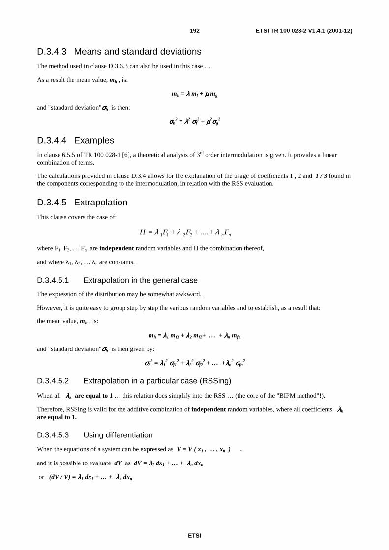
ETSI
ETSI TR 100 028-2 V1.4.1 (2001-12)192
D.3.4.3 Means and standard deviations
The method used in clause D.3.6.3 can also be used in this case …
As a result the mean value, mh , is:
mh = λλλλ mf + µµµµ mg
and "standard deviation"σσσσh is then:
σσσσh2 = λλλλ2 σσσσf
2 + µµµµ2σσσσg2
D.3.4.4 Examples
In clause 6.5.5 of TR 100 028-1 [6], a theoretical analysis of 3rd order intermodulation is given. It provides a linear combination of terms.
The calculations provided in clause D.3.4 allows for the explanation of the usage of coefficients 1 , 2 and 1 / 3 found in the components corresponding to the intermodulation, in relation with the RSS evaluation.
D.3.4.5 Extrapolation
This clause covers the case of:
nnFFFH λλλ +++= ....2211
where F1, F2, … Fn are independent random variables and H the combination thereof,
and where λ1, λ2, … λn are constants.
D.3.4.5.1 Extrapolation in the general case
The expression of the distribution may be somewhat awkward.
However, it is quite easy to group step by step the various random variables and to establish, as a result that:
the mean value, mh , is:
mh = λλλλ1 mf1 + λλλλ2 mf2+ … + λλλλn mfn
and "standard deviation"σσσσh is then given by:
σσσσh2 = λλλλ1
2 σσσσf12 + λλλλ2
2 σσσσf22 + … +λλλλn
2 σσσσfn2
D.3.4.5.2 Extrapolation in a particular case (RSSing)
When all λλλλk are equal to 1 … this relation does simplify into the RSS … (the core of the "BIPM method"!).
Therefore, RSSing is valid for the additive combination of independent random variables, where all coefficients λλλλk are equal to 1.
D.3.4.5.3 Using differentiation
When the equations of a system can be expressed as V = V ( x1 , … , xn ) ,
and it is possible to evaluate dV as dV = λλλλ1 dx1 + … + λλλλn dxn
or (dV / V) = λλλλ1 dx1 + … + λλλλn dxn

ETSI
ETSI TR 100 028-2 V1.4.1 (2001-12)193
then the above expression:
σσσσh2 = λλλλ1
2 σσσσf12 + λλλλ2
2 σσσσf22 + … +λλλλn
2 σσσσfn2
provides the statistical properties of dV or dV / V as soon as the statistical properties of
dx1 … dxn are know (e.g. the n σσσσdxn. ):
σσσσdV2 = λλλλ1
2 σσσσdx12 + λλλλ2
2 σσσσdx22 + … +λλλλn
2 σσσσdxn2
or σσσσdV/V2 = λλλλ1
2 σσσσdx12 + λλλλ2
2 σσσσdx22 + … +λλλλn
2 σσσσdxn2
as appropriate.
This relates immediately the uncertainties corresponding to the various elements of a measurement (i.e. the various contributions to the uncertainty), xi to the uncertainty of the result (i.e. the combined uncertainty).
Further proposals concerning methodologies to relate systems (e.g. a measurement set up), random variables and uncertainties can be found in clause D.5.
D.3.4.6 Case of non independent random variables
This clause covers the case where:
GFH µλ +=
F and G are non-independent random variables and H is a combination thereof,
while λ and µ are constants.
Under such circumstances, F can be written as k G .
Therefore, H = (λλλλ k + µµµµ) G and:
h ( z ) = ( 1/(λλλλ k + µµµµ ) ) g ( z / (λλλλ k + µµµµ) ) .
As a result the mean value, mh , is (using D.3.2):
mh = (λλλλ k + µµµµ) mg
and "standard deviation"σσσσh is then:
σσσσh = ( λλλλ k + µµµµ ) σσσσg
or σσσσh2 = ( λλλλ k + µµµµ ) 2 σσσσg
2 .
These results are very different from those found above, when the random variables were independent.
D.3.4.6.1 Comparison between results
If F and G had been wrongly handled as independent random variables,
σσσσh2 = λλλλ2 σσσσf
2 + µµµµ2σσσσg2
which, having, in reality σσσσf = k σσσσg
would have given σσσσh2 = λλλλ2 k2 σσσσg
2 + µµµµ2σσσσg2 = (λλλλ2 k2 + µµµµ2 ) σσσσg
2 instead!
This shows how important it is to assess, before any attempt to use "the RSS" method to identify which are the independent random variables…which may be quite difficult, if the system has not been analysed globally.

ETSI
ETSI TR 100 028-2 V1.4.1 (2001-12)194
Great care has therefore to be exercised while using the complete developed examples of calculation found in the main body of the present document, in order to identify, for a particular test set up, which are the independent random variables, and which are those which, for one or another reason, are in fact linked together (e.g. is the room temperature the same for all components, or not; has one particular instrument been used twice in the same configuration, or was it another instrument of the same type…or another configuration).
Therefore, the calculations may differ from one test set up to another test set up even if they look almost identical…(see also clause D.2.4).
D.3.4.6.2 Conclusions
As ( a + b ) 2 = a2 + b2 + 2 a b , when a and b are positive, ( a + b ) 2 > a2 + b2 .
This implies that taking random variables for independent when they are not, may lead to uncertainty values smaller than they are in reality (under estimation of the uncertainties).
D.3.5 Subtraction of random variables This clause deals with:
GFH −= ,
where F and G are independent random variables and H a combination (subtraction) thereof.
D.3.5.1 Evaluation of the corresponding distribution
When F is a random variable characterized by the fact that the probability of F having a particular value x is given by the probability density f ( x ) , then, by definition:
the probability Pf of having the random variable F having a value x such that
x1 < x < x2 is ∫=2
1
x
x
f f(x)dxP .
Similarly, we can consider ∫∞−
=x
f dtf(t)xP )( ,
and therefore (by differentiation) dPf = f ( x ) dx.
When G is also a random variable, characterized by the fact that the probability of G having a particular value y is given by the probability density g ( y ) , then, by definition:
the probability Pg of having the random variable G having a value y such that
y1 < y < y2 is ∫=2
1
y
y
g g(y)dyP .
Similarly, we can consider ∫∞−
=y
g dtg(t)yP )( ,
and therefore (by differentiation) dPg = g( y ) dy.
Should H be the random variable resulting from the subtraction of F and G ,
then its probability density h ( z ) , is to be evaluated.
For each value x of F and y of G , the value z of the random variable H is : z = x - y .

ETSI
ETSI TR 100 028-2 V1.4.1 (2001-12)195
A way to evaluate h ( z ) is as follows:
the probability of having the value of F within a very small interval [x , x + dx] is f ( x ) dx ;
the probability of having the value of G within a small interval [y1 , y2] is
g( y ) ( y2 - y1 ) = g ( y ) Dy where Dy = y2 - y1 ,
and where it is assumed that g( y1 ) = g ( y2 ) = g ( y ) (the interval is small).
The interval within which z remains has to be looked at with attention …
y1 < y2 , therefore - y1 > - y2 and x - y1 > x - y2 implying that z1 > z2 .
Under both of the above circumstances, we get the value of H within [z2 , z1] where zi = x - yi
(neglecting dx , very small compared with Dy )
and the probability of such an event (the contribution of dx in h(z) ) is f(x) dx g(y) Dy
(the probability of having both events is the product of the probability of having each event, when the events are independent).
When Dz = z1 – z2 , by definition, h ( z ) Dz is the probability of having the value of H within [z2, z1] and is, therefore, the sum of the probabilities of all the individual contributions, corresponding to all values of x :
∫+∞
∞−
= dxxfDyygDzzh )()()( .
Since Dz = z1 – z2 = x – y1 – ( x – y2) = y2 - y1 = Dy ,
we have Dz = Dy and noting that y = x –z , the integral above becomes
∫+∞
∞−
−= dxxfDzzxgDzzh )()()(
which can be simplified into ∫+∞
∞−
−= dxxfzxgzh )()()(
This equation provides the value of h ( z ) as a function of f ( x ) and g ( y ) … which is the relation between the probability densities corresponding to the random variables F , G and H.
D.3.5.2 Verifications
When providing the definitions and characteristics of probability densities characterizing random variables, 2 criteria had been expressed. The probability density associated with H , h ( z ) shall be such that:
- 0≥h(z)
- ∫+∞
∞−
=1dzh(z)
It is therefore wise to verify the 2 properties, which, in practise, could help detecting problems occurred during the calculations.
Obviously, when 0≥∀ f(x)x and 0≥∀ g(y)y
then 0( ≥z)h .

ETSI
ETSI TR 100 028-2 V1.4.1 (2001-12)196
Concerning the second relation, verifications can be done in a generic manner (i.e. not depending on specific distributions):
∫+∞
∞−
=dzh(z) =−∫∫+∞
∞−
+∞
∞−
dzdxf(x)zxg )( dxdzzxgxf ∫∫+∞
∞−
+∞
∞−
− ])([)(
By introducing t = x- z ( dt = - dz , where x is considered as a constant) , this equation may be transformed into:
= ∫ ∫+∞
∞−
−∞
∞+
=− dxdttgxf ])1()([)( ∫ ∫+∞
∞−
+∞
∞−
=dxdttgxf ])([)( ∫+∞
∞−
=dxxf ]1[)( 1∫+∞
∞−
=f(x)dx .
Which ensures that h ( z ) can be a proper probability density function characterizing some random variable (hopefully H, should the above calculations be correct!).
D.3.5.3 Means and standard deviations
The method for evaluating the mean and the standard deviation for a number of operations discussed in clause D.3 is very similar.
D.3.5.3.1 Mean value
In the case of a subtraction of random variables, it has been shown that the resulting density of probability is:
∫+∞
∞−
−= dxxfzxgzh )()()( .
The general expression of mh being:
∫+∞
∞−
= dzzhzmh )( ,
it comes that
dzdxxfzxgzmh ∫∫+∞
∞−
+∞
∞−
−= )()(
∫∫+∞
∞−
+∞
∞−
−= dxxfdzzxgzmh )(])([ .
For each particular value of x , the internal integral can be easily calculated by a simple change in variable: t = x - z .
Under these circumstances, dz = - dt and:
dxxfmxdxxfdttgtxdxxfdzzxgzm gh )()()(])()([)(])([ −=−=−= ∫∫∫∫∫+∞
∞−
+∞
∞−
+∞
∞−
+∞
∞−
+∞
∞−
and gfh mmm −= .
As a result the mean value, mh , is:
mh = mf - mg
which is valid independently of the distributions addressed (i.e. should they be normal or not).

ETSI
ETSI TR 100 028-2 V1.4.1 (2001-12)197
D.3.5.3.2 Standard deviation
In the present case, we have:
∫+∞
∞−
−= dxxfzxgzh )()()( .
The general expression of sh2 being:
∫+∞
∞−
= dzzhzsh )(22 ,
it comes that:
dzdxxfzxgzsh ∫∫+∞
∞−
+∞
∞−
−= )()(22
∫∫+∞
∞−
+∞
∞−
−= dxxfdzzxgzsh )(])([ 22.
For each particular value of x , the internal integral can be easily calculated by a simple change in variable: t = x - z .
Under these circumstances, dz = - dt and:
∫∫∫∫+∞
∞−
+∞
∞−
+∞
∞−
+∞
∞−
−=−= dxxfdttgtxdxxfdzzxgzsh )(])()([)(])([ 222
∫∫∫∫+∞
∞−
+∞
∞−
+∞
∞−
+∞
∞−
+−=−= dxxfdttgtxtxdxxfdttgtxsh )(])()2([)(])()([ 2222
∫∫∫∫+∞
∞−
+∞
∞−
+∞
∞−
+∞
∞−
+−=+−= dxxfdttgttgxttgxdxxfdttgtxtxsh )(]))()(2)(([)(])()2([ 22222
22222 2)(])2)1(([ ggffggh smmsdxxfsmxxs +−=+−= ∫+∞
∞−
.
Noting the relation 222 ms −=σ (or 2 2 2s mσ= + ),
we then get:
2 2 2 2 2 2( ) 2 ( )h h f f f g g gm m m m mσ σ σ+ = + − + +
222222 2 gggfffhh mmmmm ++−+=+ σσσ and replacing mh by its value
( ) 222222 2 gggfffgfh mmmmmm ++−+=−+ σσσ
and, after lots of sweat and tears …. and noting that ( ) 2 22 2f g f f g gm m m m m m− = − +
we get (simplifying):
222gfh σσσ += ,

ETSI
ETSI TR 100 028-2 V1.4.1 (2001-12)198
which is valid independently of the distributions addressed (i.e. should they be normal or not).
(alternatively, it could have been written:
2h
2h
2h
2h
2h
2h
ms
ms
+=∴
−=
σ
σ
Hence,
( )
2g
2f
2g
2g
2f
2f
2h
2g
2f
2g
2f
2h
2ggf
2f
2ggf
2f
2h
2ggf
2f
2gf
2h
msms
ssmm
smm2smmm2m
smm2smm
σσσ
σ
σ
σ
+=−+−=
+=++
+−=+−+
+−=−+
which provides the same result …)
D.3.5.4 Examples
The fact that RSSing is used for both additions and subtractions of random variables may have hidden the use of subtractions in the numerous examples found in the present document.
Substitution measurements are favoured for radio equipment. This is certainly an area where subtractions may have to be performed.
D.3.5.5 Subtracting several distributions
In order to avoid problems with the signs, operations involving several distributions have to be done more carefully than in the case of additions, e.g. handling one operation at the time (step by step approach).
D.3.6 Multiplication of random variables This clause deals with:
GFH = .
where F and G are independent random variables and H is a combination (multiplication) thereof.
Problems may be found, when the value of F or G is zero … (or too often equal to zero, creating possible convergence problems). Should this occur, then in that particular case, careful attention should be devoted to the situation.
As written above, the operation is symmetrical in relation to F and G. However, the expression found below is not.
By exchanging the role of F and G (or the role of x and y ) another expression may be found, which, in some cases could be more friendly for a particular usage.

ETSI
ETSI TR 100 028-2 V1.4.1 (2001-12)199
D.3.6.1 Evaluation of the corresponding distribution
When F is a random variable characterized by the fact that the probability of F having a particular value x is given by the probability density f ( x ) , then, by definition:
the probability Pf of the random variable F having a value x such that:
x1 < x < x2 is ∫=2
1
x
x
f f(x)dxP .
Similarly, we can consider ∫∞−
=x
f dtf(t)xP )( ,
and therefore (by differentiation) dPf = f ( x ) dx.
When G is also a random variable, characterized by the fact that the probability of G having a particular value y is given by the probability density g ( y ) , then, by definition:
the probability Pg of the random variable G having a value y such that:
y1 < y < y2 is ∫=2
1
y
y
g g(y)dyP .
Similarly, we can consider ∫∞−
=y
g dtg(t)yP )( ,
and therefore (by differentiation) dPg = g( y ) dy.
Should H be the random variable resulting from the multiplication of F and G ,
then its probability density h ( z ) , is to be evaluated.
For each value x of F and y of G , the value z of the random variable H is : z = x y .
In fact, in the following, the situation is slightly different when x < 0 (the situation is comparable with that discussed
in the case where λ was negative, in clause D.3.2).
The way to evaluate h ( z ) is quite simple, and is given in the following.
The probability of having the value of F within a very small interval [x , x + dx] is f ( x ) dx ;
the probability of having the value of G within a small interval [y1 , y2]
is g( y ) ( y2 - y1 ) = g ( y ) Dy (where Dy = y2 - y1 ,
and where it is assumed that g( y1 ) = g ( y2 ) = g ( y ) , Dy being considered as small );
when both events occur,
then, the value of H is within [z1 , z2] where zi = x yi
(neglecting dx , considered to be very small compared with Dy )
and the probability of such an event (which provides the contribution of dx in h( z ) ) is
f( x ) dx g( y ) Dy .

ETSI
ETSI TR 100 028-2 V1.4.1 (2001-12)200
Case where x > 0.
When Dz = z2 - z1 , by definition, h ( z )Dz is the probability of having the value of H within [z1, z2] and is, therefore, the sum of the probabilities of all the individual contributions, corresponding to all positive values of x :
∫+∞
=0
)()()( dxxfDyygDzzh .
Since Dz = z2 - z1 = x y2 – x y1 = x ( y2 – y1 ) = x Dy ,
we have Dz = x Dy and noting that y = z / x ( x non zero!) , the integral above becomes
∫+∞
=0
)()/)(/()( dxxfxDzxzgDzzh .
Case where x < 0.
When Dz = z2 - z1 , by definition, h ( z )Dz is the probability of having the value of H within [z1, z2] (where [z1, z2] is an interval and therefore z1 < z2 ) and is, therefore, the sum of the probabilities of all the individual contributions, corresponding to all negative values of x :
∫∞−
=0
)()()( dxxfDyygDzzh .
Since Dz and Dy are intervals, Dz = z2 - z1 = | x | y2 – | x | y1 = | x | ( y2 – y1 ) = - x Dy ,
we have Dz = - x Dy and noting that y = z / x ( x non zero!) , the integral above becomes
∫∞−
−=0
)()/)(/()( dxxfxDzxzgDzzh .
Taking into account both positive and negative contributions of x , and simplifying by Dz ,
the two expressions above can be combined into ∫+∞
∞−
= dxxfx
zg
xzh )()()
1()(
This relation provides the value of h ( z ) as a function of f ( x ) and g ( y ) … which is the sought relation between the probability densities corresponding to the random variables F , G and H.
NOTE 1: When F or G take zero as a value, then the value of H is also zero, independently of the other random variable …
NOTE 2: In the expression above, f and g have roles slightly different, which is not the case with H = F G.
As a result, the expression (obtained by permutation):
∫+∞
∞−
= dyy
zfyg
yzh )()()
1()( should be as much appropriate as the expression given above, but
could be more convenient in some cases i.e. when the variable y can be mapped to a physical variable which never reaches zero.

ETSI
ETSI TR 100 028-2 V1.4.1 (2001-12)201
D.3.6.2 Verifications
When providing the definitions and characteristics of probability densities characterizing random variables, 2 criteria had been expressed. The probability density associated with H , h ( z ) shall be such that:
- 0≥h(z)
- ∫+∞
∞−
=1dzh(z)
It is therefore wise to verify the 2 properties, which, in practise, could help detecting problems occurred during the calculations.
Obviously, when 0≥∀ f(x)x and 0≥∀ g(y)y
then: 0( ≥z)h .
This situation is close to that when lambda was negative …in clause D.3.2.
The verifications can be done in a generic manner, but with the help of the function ε (see clause D.3.10.3):
∫+∞
∞−
=dzh(z) =∫∫+∞
∞−
+∞
∞−
dzdxf(x)xxzg )/)(/( ε dxdzxzgxfx ])/([)()/( ∫∫+∞
∞−
+∞
∞−
ε
By introducing t = z / x ( dt = dz / x , x being considered as a constant, within the inside integral ) ,
this expression may be split into 2 parts and then transformed into:
∫ ∫+∞ +∞
∞−
=0
])([)()()/1( dxdttgxxfx ∫+∞
=0
]1[)( dxxf I ,
when x > 0 and ε = 1.
And ∫ ∫∞−
−∞
∞+
=−0
])([)()()/1( dxdttgxxfx ∫∞−
=0
]1[)( dxxf J
when x < 0 and ε = - 1.
Finally, it can be noted that I + J = 1 ,
which ensures that h ( z ) can be a proper probability density function characterizing some random variable (hopefully H, should the above calculations be correct!).
D.3.6.3 Means and standard deviations
It has been indicated above that, using the function ε:
∫+∞
∞−
= dxxfx
zg
xzh )()()
1()(ε
.
The general expression of mh being:
∫+∞
∞−
= dzzhzmh )( ,

ETSI
ETSI TR 100 028-2 V1.4.1 (2001-12)202
it comes that:
dzdxxfx
zg
xzmh ∫∫
+∞
∞−
+∞
∞−
= )()()(ε
∫∫+∞
∞−
+∞
∞−
= dxxfdzx
zgz
xmh )(])()[(
ε.
For each particular value of x, the internal integral can be easily calculated by a simple change in variable: y = ( z / x ).
Under these circumstances, dz = x dy and , splitting again into 2 parts:
dxxfxxmx
dxxfxdyygxyx
dxxfdzx
zgz
xm gh )(])[
1()(])()[
1()(])()[
1(
000∫∫∫∫∫+∞+∞
∞−
+∞+∞
∞−
+∞
===+
dxxfxxmx
dxxfxdyygxyx
dxxfdzx
zgz
xm gh )(])[
1()(])()[
1()(])()[
1(
000
∫∫∫∫∫∞−
−∞
∞+∞−
+∞
∞−∞−
=−=−=−
and reassembling the 2 parts it comes that : fggh mmdxxfxmm ∫+∞
∞−
== )( .
As a result the mean value, mh , is:
mh = mf mg
which is valid independently of the distributions addressed (i.e. should they be Normal or not).
A similar method can be used for the standard variation:
∫+∞
∞−
= dzzhzsh )(22
Therefore,
dxdzx
zgzxf
xdxdzxf
x
zg
xzsh ∫ ∫∫∫
∞
∞−
∞
∞−
∞
∞−
∞
∞−
=
= 222 )()(εε
Integrating by substitution, disassembling on ε and reassembling (as above):
( ) ( ) 222223
22 )()()()()( gfgh ssdxxfxsdxdyygyxfx
xdxxdyygxyxf
xs ==
=
= ∫∫ ∫∫ ∫
∞
∞−
∞
∞−
∞
∞−
∞
∞−
∞
∞−
ε
ε
ε
Noting,
222 ms −=σ

ETSI
ETSI TR 100 028-2 V1.4.1 (2001-12)203
Then,
)m)(m(m
ssms
2g
2g
2f
2f
2h
2h
2g
2f
2h
2h
2h
++=+∴
=+=
σσσ
σ
The expression above,
σσσσh2 + mh
2= (σσσσf2 + mf
2 )( σσσσg2 + mg
2 )
recalls to a certain extent that found for the addition of random variables …
D.3.6.4 Examples
The results found above are the basis for the handling of influence quantities, in clause D.4.1.
D.3.6.5 Extrapolations
Independently of the distributions handled, a step by step method based on the properties shown above would provide,
for KGFH = :
mh = mf mg mk ...
and σσσσh2 + mh
2= (σσσσf2 + mf
2 )( σσσσg2 + mg
2 )( σσσσk2 + mk
2 ) …
A similar expression will be found in clause D.4.2.2.
D.3.7 Inversions and divisions Again, it would be possible to find the sought results either by direct methods or by application of clauses D.3.9 and D.3.11 … or with D.3.10 …
The latter approach has been preferred: rather than starting from scratch (as done for the multiplication in clause D.3.6), a step by step approach using results already established ("the building bloc approach") was used to establish the properties relating to:
Y = 1 / XY = 1 / XY = 1 / XY = 1 / X and H = F / GH = F / GH = F / GH = F / G ....
D.3.7.1 Evaluation of distributions corresponding to inversions
(The notations proposed in clause D.3.10.6 have been used).
This clause deals with Y = 1 / XY = 1 / XY = 1 / XY = 1 / X (using the character set Monotype Corsiva) ,
where X is a random variable and Y is its transformed by the inversion g , where g is obviously a function of one variable which is monotonous (therefore clauses D.3.9 and possibly D.3.10.3 apply).
X is a random variable characterized by the fact that the probability of X having a particular value x is given by the probability density X ( x ).
By definition, the probability P of having the values x taken by the random variable X such that
x1 < x < x2 is ∫=2
1
x
x
dxX(x)P .

ETSI
ETSI TR 100 028-2 V1.4.1 (2001-12)204
Similarly, we can consider ∫∞−
=x
X dtX(t)xP )( ,
and, by differentiation : dPX = X ( x ) dx .
Y is the random variable which probability density is Y ( y ) (to be evaluated).
g | x y = g (x) = 1 / x
g' | x y' = g' (x) = - 1 / x2
As a result from clause D.9.1:
))(('
))((1
1
zgg
zgfh(z)
−
−
= or, with the notations used here:
))(('
))((1
1
ygg
ygXY(y)
−
−
= where
g-1 | y x = 1 / y .
Therefore we have:
yy
X
yg
yX
Y(y)2
)1
(
)1
('
)1
(
−== .
Finally, the sought probability density is : )1
(1
2 yXY(y)
y=
D.3.7.2 Verification in the case of the inversion
Obviously Y is positive.
Should Y be a distribution then
1)
1(
)(2
== ∫∫∞+
∞−
∞+
∞−
dyy
yX
dyyY would be true.
This integral can be easily calculated using the variable x such that:
x = 1 / y dx = - ( dy ) / y2
and, as a result,
∫∫∫+∞
∞−
+∞
∞−
+=0
0
)()()( dyyYdyyYdyyY replacing Y ( ) by its expression

ETSI
ETSI TR 100 028-2 V1.4.1 (2001-12)205
dyy
yX
dyy
yX
dyyY ∫∫∫∞+
∞−
∞+
∞−
+=0
2
0
2
)1
()1
()( or after the substitution
dxyy
xXdxy
y
xXdyyY )(
)()(
)()( 2
0
20
22 −+−= ∫∫∫
∞+
−∞+∞
∞−
.
dxxXdxxXdyyY )()()(0
0∫∫∫∞+
−∞+∞
∞−
−−= (by simplification)
1)()()( ==−= ∫∫∫+∞
∞−
−∞
∞+
+∞
∞−
dxxXdxxXdyyY
and Y fulfils the 2 requirements indicated; so it can be a valid expression for a probability density.
The method used for the verification can be extended to support also the calculation of the mean, below.
D.3.7.3 Means and standard deviations in the case of the inversion
D.3.7.3.1 Mean value
By definition, the mean is:
dyyyYmy )(∫+∞
∞−
= .
Replacing Y by its value provides:
1)
1(
)( 2 == ∫∫∞+
∞−
∞+
∞−
dyyy
yX
dyyyY .
This integral can be easily calculated using the variable x such that:
x = 1 / y dx = - ( dy ) / y2
and, as a result,
∫∫∫+∞
∞−
+∞
∞−
+=0
0
)()()( ydyyYydyyYydyyY and replacing Y ( ) by its expression gives
ydyy
yX
ydyy
yX
ydyyY ∫∫∫∞+
∞−
∞+
∞−
+=0
2
0
2
)1
()1
()(
dxx
yy
xXdx
xy
y
xXydyyY )
1)((
)()
1)((
)()( 2
0
20
22 −+−= ∫∫∫
∞+
−∞+∞
∞−

ETSI
ETSI TR 100 028-2 V1.4.1 (2001-12)206
dxx
xXdxx
xXdyyyY )1
)(()1
()()(0
0∫∫∫∞+
−∞+∞
∞−
−−=
dxx
xXdx
xxXdyyyYmy
)()
1()()( ∫∫∫
+∞
∞−
−∞
∞+
+∞
∞−
=−== .
This expression looks like moment ( - 1) of the probability density X … not that much friendly!
NOTE: this expression could have been obtained directly using the results of clause D.9.3. However, since this expression is somewhat different from expressions found in other clauses of the present annex, it was felt wise to obtain it also directly.
D.3.7.3.2 Comment concerning the mean value
As indicated above,
dxx
xXmy
)(∫
+∞
∞−
= .
Should the distribution X correspond to a constant x0 , then, the above expression could be simplified:
000
1)1(
1)(
1)(xx
dxxXx
dxx
xXmy ==== ∫∫
+∞
∞−
+∞
∞−
and we would also have 0xmx = .
In this case (only) we would get: x
y mxm
11
0
== …. An expression that we could have expected.
D.3.7.3.3 Standard deviation
The results found in clause D.3.7.3.1 support a calculation of the standard variation using the results of clause D.3.9.3 which provides directly (by substituting the names of the variables):
dxx
xXdxxXxgmyy 2
222 )()()( ∫∫
+∞
∞−
+∞
∞−
==+σ .
As in the case of the mean, should the distribution X correspond to a constant x0 , then,
the above expression could also have been simplified:
2
0
2
02
0
22 )1
()()1
()(
xdxxX
xdx
x
xXmyy ===+ ∫∫
+∞
∞−
+∞
∞−
σ
and we would also have 0xmx = and 0
1x
my = .
In this case (only) we would get: 2
0
2
0
222 )1
()1
(xx
m yyy =+=+ σσ ….
And 02 =yσ which is fair for a constant!

ETSI
ETSI TR 100 028-2 V1.4.1 (2001-12)207
D.3.7.4 Examples of inversions
Ohm's law can be expressed as v = r i , as well as i = v / r .
D.3.7.4.1 Evaluation of the distribution
To simplify the calculations, in the following, v = 1 (clause D.3.2 indicates how to handle a multiplication by a constant, so it is very simple to introduce another value and to derive the corresponding result when necessary).
Using the notations of clause D.10.6 , we can therefore consider the case where R is a rectangular distribution.
In this case, the probability density I is given by clause D.3.7.1 i.e.:
)1
(1
2 yXY(y)
y= where y = 1 / x .
The relation between the relevant variables is as follows:
y i
x r .
And with the appropriate names of variables and notations, we get:
)1
(12 i
Ri
I(i) = , where R is a rectangular distribution with a spread from r1 to r2 or 2 A (as
defined in clause D.1.3.1).
When r1 < ( 1 / i ) < r2 then Ai
I(i)211
2= ; otherwise I ( i ) = 0.
The corresponding distribution is therefore represented by a chunk of curve between two vertical lines (corresponding to 1 / r1 and 1 / r2 ), looking like a somewhat trapezoidal distribution.
D.3.7.4.2 Evaluation of the mean value
The general expression for the mean value is provided in clause D.3.7.3.1 , and as a result, in the case of a rectangular distribution:
)]([ 2
1
2
1
2
121
21)()( rLog
r
r
r
r
r
r
i Adr
Ardr
r
rRdr
r
rRm ==== ∫∫∫
+∞
∞−
and )]([1
221
rr
LogA
mi = .
Noting that if r0 is the middle of [r1 , r2 ] , we have r2 = r0 + A and r1 = r0 – A ,
mi can be expressed as: ]/1/1
[)]([0
021
0
021
rArA
LogArAr
LogAA
mi −+
−+
== .

ETSI
ETSI TR 100 028-2 V1.4.1 (2001-12)208
When A is small compared to r0 … we can use Log ( 1 + x ) equivalent to x and, therefore:
00
122
0021 )]/()/[(
rrA
A
Am rArAi ==≈ −−+ …
not very surprising (but gives confidence!) : when v = 1 and r = r0 … i = ( v / r ) = 1 / r0 !
The approximation used for the expression of mi although precise enough for the purpose of this clause, has to be enhanced for the needs of clause D.3.7.4.3. As a result, a better approximation of Log ( 1 + x ) has to be used:
)(32
)1( 332
xxx
xxLog ε++−=+ .
And, therefore, ))/1()/1((21
0
021
00]/1/1
[ rALogrALogAA
mrArA
Logi −−+==−+
))])(()(31
)(21
)(()))(()(31
)(21
)[((21 3
0
3
0
2
00
3
0
3
0
2
00 r
A
r
A
r
A
r
A
r
A
r
A
r
A
r
A
Ami εε +−+−−−−++−=
and, after another crash of Word 97 ™ with loss of information … another attempt to type in the text provides:
)])((23
11[
1))])(()(
32
)(2[(21 3
0
02
0
2
0
3
0
3
00 r
A
A
r
r
A
rr
A
r
A
r
A
Ami εε ++=++= ,
another expression of the mean, which will be used in the next clause.
It can be noted, that the offset relating to the mid-point is equal to: 20
2
0 3
11
r
A
r .
The value of this offset was not visible with a first order approximation.
D.3.7.4.3 Evaluation of the standard deviation
What would then be the standard deviation ? Its value, in the general case is provided by:
dxx
xXmyy 2
22 )(∫+∞
∞−
=+σ .
When R is rectangularly distributed, we get:
)11
(21
21
21)()(
21222
22 ]1
[2
1
2
1
2
1rrAA
drrA
drr
rRdr
r
rRm
r
r
r
r
r
r
r
ii −=====+−
∫∫∫∞+
∞−
σ
)1
()(21
)11
(21
2121
12
21
22
rrrr
rr
ArrAmii =−=−=+σ .
When writing r2 = r0 + A and r1 = r0 – A , as above, and using approximations,
we get:
( )( )
20
20
20
2000
2021
22 /1
)/1(
1
)/1()/1(
11
r
rA
rArrArArrrmii
+≈−
=−+
==+σ ,

ETSI
ETSI TR 100 028-2 V1.4.1 (2001-12)209
and replacing the mean by its approximate value:
)])((31
1[1 3
0
02
0
2
0 r
A
A
r
r
A
rmi ε++=
)])((32
1[1
)])((31
1[1 3
0
02
0
22
0
23
0
02
0
22
0
2
r
A
A
r
r
A
rr
A
A
r
r
A
rmi εε ++
=++
=
and:
( )]1[
1/1)])((
32
1[1
20
2
20
20
203
0
02
0
22
0
2
r
A
rr
rA
r
A
A
r
r
A
ri +=+≈++
+ εσ
or, finally:
311
)32
1(1
20
2
20
20
2
20
2
r
A
rr
A
ri =−≈σ .
NOTE: It can be noted, that the use of a first order approximation for the mean would provide a wrong result:
( )2
0
20
20
2 /11
r
rA
ri
+≈+σ or 20
20
22 1
rr
Ai ≈σ .
This value would have been in excess of the correct value found above.
D.3.7.4.4 Comments concerning the standard deviation
The result found above (in clause D.3.7.4.3) is not surprising:
it recalls the expression of the standard deviation of a rectangular distribution having, as a footprint, the extremes values of the intensity corresponding to the extreme values of the footprint of R .
It can also be noted that the "simplification" v = 1 , results in the loss of the term expressed in Volts, and, therefore, a checked based in units (see clause D.3.10.7) becomes difficult.
As a result, it can be wise to reintroduce this constant v . Using the results of clause D.3.2 , we get:
0r
vmi ≈ and 2
0
2
20
22
31
r
v
r
Ai ≈σ .
With these values, should a footprint of i have been defined by its spread of + B , then, we would have had:
00 r
A
i
B = , when requiring corresponding extreme values.
For a rectangular distribution i of spread of + B , then we would have had (see clause D.1.3.1):
202
0
2
20
20
222
31
33i
r
A
r
iABiB ===σ where 2
0
22
0r
vi = , and therefore,
20
2
20
22
31
r
v
r
AiB =σ .

ETSI
ETSI TR 100 028-2 V1.4.1 (2001-12)210
The two expressions 2
iBσ and 2
iσ :
- resulting respectively from a rectangular distribution (i + B)
- and from the inverse of a rectangular distribution (r + R)
have obviously the same structure and, with the approximations made, the same coefficient.
Therefore, in order to find differences due to the differences in the shapes of the corresponding distributions it would have been necessary to use approximations at an higher order, so that the influence of the approximations made in the calculations of the standard deviation … would not have hidden the effects!
However, this example shows the method to handle this type of problems and type of results which can be expected when using the methodology developed in this clause.
D.3.7.5 Evaluation of the distribution corresponding to divisions
(The notations proposed in clause D.3.10.6 have, once again, been used).
This clause deals with H = F / G (using the character set Monotype Corsiva)
Where F and G are independent random variables and H is the result of the division of F by G .
Let Y be the inverse of G … H can therefore be considered as the product of F by Y
and clauses D.3.6 and D.3.7.1 apply...
Y = 1 / G H = F * Y
When F is a random variable characterized by the fact that the probability of F having a particular value f is given by the probability density F ( f ) ,
by definition, the probability P of having the values f taken by the random variable F such that
f1 < f < f2 is ∫=2
1
f
f
dfF(f)P .
Similarly, we can consider ∫∞−
=f
F dtF(t)fP )( ,
and therefore (by differentiation) dPF = F ( f ) df .
When G is a random variable characterized by the fact that the probability of G having a particular value g is given by the probability density G ( g ) ,
by definition, the probability P of having the values g taken by the random variable G such that
g1 < g < g2 is ∫=2
1
g
g
dgG(g)P .
Similarly, we can consider ∫∞−
=g
G dtG(t)gP )( ,
and therefore (by differentiation) dPG = G ( g ) dg .
H is the random variable which probability density is H ( h ) (to be evaluated).

ETSI
ETSI TR 100 028-2 V1.4.1 (2001-12)211
By definition, Y is the inverse of G and, therefore, its probability density is (see clause D.7.1): )1
(1
2 yGY(y)
y= .
The probability density of the product of random variables is, according to D.3.6.1:
∫+∞
∞−
= dxxfx
zg
xzh )()()
1()( .
With the variables and notations used in this clause,
| h z H h
| f x F f
| g y Y y
and we get:
∫+∞
∞−
= dffFf
hY
fhH )()()
1()( or, substituting Y ( ) by its value:
∫+∞
∞−
= dffF
h
fG
f
hfhH )()(
1)
1()( 2 .
After simplification we get:
( )( ) ( )∫∫
+∞
∞−
+∞
∞−
== dffFh
fG
h
fdffF
h
fG
h
f
fhH )()()()()
1()( 22
2
,
or using ε as proposed in D.10.3
( )∫+∞
∞−
= dffFh
fG
h
fhH )()()( 2
ε
D.3.7.6 Verification in the case of divisions
Obviously H is positive.
Should H be a distribution then
( ) 1)()()( 2 == ∫∫∫+∞
∞−
+∞
∞−
+∞
∞−
dhdffFh
fG
h
fdhhH
ε would be true.
Reordering the terms we get:
( ) dffFfdhh
fG
hdhhH )(])([)( 2∫∫∫
+∞
∞−
+∞
∞−
+∞
∞−
= ε .

ETSI
ETSI TR 100 028-2 V1.4.1 (2001-12)212
The internal integral is now easy to calculate using a new variable z and considering f as a constant:
z = f / h dz = - ( f dh ) / h2 and, as a result,
- when f (and ε ) is positive
( ) ( ) ( )∫∫∫+∞
∞−
+∞
∞−
+=0
2
0
22 )(1
)(1
)( dhh
fG
hdh
h
fG
hdh
h
fG
h
ε
( ) ( ) ( )∫∫∫∞+
−∞+∞
∞−
−+−=0 2
20
2
22 )1()(1
)1()(1
)( dzf
hzG
hdz
f
hzG
hdh
h
fG
h
ε
( ) ( ) fdzzG
fdz
f
hzG
hdh
h
fG
h
1)(
1)1()(
1)(
2
22 =+=−= ∫∫∫+∞
∞−
−∞
∞+
+∞
∞−
ε
- when f (and ε ) is negative
( ) ( ) ( )∫∫∫+∞
∞−
+∞
∞−
−+−=−
02
0
22 )(1
)(1
)(1
dhh
fG
hdh
h
fG
hdh
h
fG
h
( ) ( ) ( )∫∫∫∞−
+∞+∞
∞−
−−+−−=0 2
20
2
22 )1()(1
)1()(1
)( dzf
hzG
hdz
f
hzG
hdh
h
fG
h
ε
( ) ( ) fdzzG
fdz
f
hzG
hdh
h
fG
h
1)(
1)(
1)(
2
22 =+== ∫∫∫+∞
∞−
−∞
∞+
+∞
∞−
ε .
In both cases the result is expressed in the same way, so finally we have:
( ) 1)()(1
)(])([)( 2 ==== ∫∫∫∫∫+∞
∞−
+∞
∞−
+∞
∞−
+∞
∞−
+∞
∞−
dffFdffFff
dffFfdhh
fG
hdhhH
ε
and H fulfils the 2 requirements indicated; so it can be a valid expression for a probability density.
D.3.7.7 Means and standard deviations in the case of divisions
D.3.7.7.1 Corresponding evaluation
The mean and the standard deviation are provided, in the case of a multiplication, in clause D.3.6.3:
with the notations of that clause:
gfh mmm = and ))(( 222222ggffhh mmm ++=+ σσσ .
With the present notations, we get for the mean:
yfh mmm = and substituting m y by its value, as given in clause D.3.7.3
dxx
xXmy
)(∫
+∞
∞−
= ,

ETSI
ETSI TR 100 028-2 V1.4.1 (2001-12)213
the expression of the mean becomes, with the appropriate variables
dgg
gGmm fh
)(∫
+∞
∞−
= .
With the present notations, we get for the standard deviation:
))(( 222222yyffhh mmm ++=+ σσσ
and substituting )( 22yy m+σ by its value, as given in clause D.3.7.3
dxx
xXmyy 2
22 )(∫
+∞
∞−
=+σ ,
the expression providing the standard deviation becomes, with the appropriate variables
dgg
gGmm ffhh 2
2222 )()( ∫
+∞
∞−
+=+ σσ .
D.3.7.7.2 Comments
Clause D.3.6.3 provides:
fgh mmm = .
Using once again Ohm's law, we have v = r i , and irv mmm =
As a result, of a quick calculation, it could have been tempting to write:
r
vi m
mm = .
However, the result provided above, in clause D.3.7.7.1 is:
dgg
gGmm fh
)(∫
+∞
∞−
= , which, with the notations corresponding to Ohm's law, i = v / r
become
drr
rRmm vi
)(∫
+∞
∞−
= … so what ? Would normally, drr
rR
mr
)(1∫
+∞
∞−
= ?
The example provided in clause D.3.7.4 does not suggest it. So ?
A key can be found in the definitions.
In clause D.3.7.5, it is indicated:
" F and G are independent random variables and H is the result of the division of F by G ".
So, in this case, the independent random variables are VVVV and RRRR … while in the other case, the independent random variables were RRRR and I I I I .
The importance of clearly identifying which random variables are independent and which are not, had already been stressed in clauses such as D.2.4 or D.3.4.6. When this is not done carefully, there is a clear risk of getting wrong results.

ETSI
ETSI TR 100 028-2 V1.4.1 (2001-12)214
D.3.7.8 Examples in the case of divisions
In clause D.3.7.7.2 above, an example with Ohm's law was already discussed.
D.3.8 Using Logs and dBs
This clause deals with )(FLogH = and dBs
Where F is a random variable and H its Logarithm.
It is supposed that F has only positive values.
In clause D.3.8.1 a direct method has been used. In clause D.3.8.4 the method used is based on the results of clause D.3.9 (using functions). Substitutions (see clause D.10.3) could also have been used.
D.3.8.1 Evaluation of the corresponding distribution
When F is a random variable characterized by the fact that the probability of F having a particular value x is given by the probability density f ( x ) , then, by definition:
the probability Pf of having the random variable F having a value x such that
x1 < x < x2 is ∫=2
1
x
x
f f(x)dxP .
Similarly, we can consider ∫∞−
=x
f dtf(t)xP )( ,
and therefore (by differentiation) dPf = f ( x ) dx .
In the following, x is supposed within the definition range of the function Log i.e. x is supposed positive.
Should H be the random variable corresponding to H = Log ( F ) (using log e ) ,
then, with the current notations, its probability density h ( z ) , is to be evaluated.
For each value of F , the value z of the random variable H is : z = Log ( x ) .
The way to evaluate h ( z ) is very simple:
when the value of F is within [ x , x + dx ] , event having a probability f ( x ) dx
the value of H is within [ Log ( x ) , Log ( x + dx ) ] ,
event having a probability h ( z ) dz .
This means that these two events have the same probability, and, therefore:
f ( x ) dx = h ( z ) dz .
When the value of F is x , the value of z is z = Log ( x ) .
We will also have, dz = ( 1 / x ) dx , and zex = .

ETSI
ETSI TR 100 028-2 V1.4.1 (2001-12)215
Replacing, we get:
dP = h ( z ) dz = f ( x ) dx h ( z ) (1 / x ) dx = f ( x ) dx , which, in turn, gives:
h ( z ) = x f ( x ) , or )( zz efeh(z) =
the relation between the probability densities corresponding to the random variables F and H
(when using log e (caution: dB calculations utilize log 10 )).
D.3.8.2 Verifications
When providing the definitions and characteristics of probability densities characterizing random variables, 2 criteria had been expressed. The probability density associated with H , h ( z ) shall be such that:
- 0≥h(z)
- ∫+∞
∞−
=1dzh(z)
It is therefore wise to verify the 2 properties, which, in practise, could help detecting problems occurred during the calculations.
Obviously, ze is positive and f is such that 0≥∀ f(x)x , therefore 0( ≥z)h .
Concerning the second relation, verifications can be done in a generic manner: ∫+∞
∞−
=dzh(z)
∫+∞
∞−
dz)zf(z )exp())(exp(
By introducing t = exp (z ) dt = t dz , this equation may be transformed into:
∫+∞
∞−
=dttf(tt )/1() 1∫+∞
∞−
=f(t)dt .
Which ensures that h ( z ) can be a proper probability density function characterizing some random variable (hopefully H , should the above calculations be correct!).
D.3.8.3 Mathematical support for calculations with Logs and dBs
)a(log
)N(log)N(log
)Nln()N(logxeN
)Nlog()N(logx10N
b
ba
ex
10x
=
==⇒=
==⇒=
1mlogm =

ETSI
ETSI TR 100 028-2 V1.4.1 (2001-12)216
x
)e(log))'x((log a
a ⇒
xe
)xln())e((log)x(log
)xln(
1010
=
=
)aln(ea zz =
…and …
Log ( 1 + x ) = x – ( x 2 / 2 ) + ( x 3 / 3 ) …
log10 = (Log x) / (Log 10)
(Log x )' = 1 / x
D.3.8.4 Using dBs
In order to write this clause, a direct calculation could have been performed …
Using the various elementary operations described in the clauses above, it would also have been possible to chain a number of those elementary operations (the method using "building blocks) … and reach the sought result!
However, the more elegant way is probably to combine all operations in one single transformation, using the results found in clause D.3.9 (below).
As it has already been noted, annex E also refers to conversions … and the results are consistent!
When thinking in dBs and linear terms, before any further action, the first thing to do is to try and understand the situation, and to settle on the best strategy.
Are the uncertainties (probability densities) relating to the various elements of the test set up expressed in dB or in linear terms?
If the uncertainties are given in dBs (e.g. the attenuation of a 10 dB attenuator given as +0,1 dB …) then dBs have to be used, at least for a while … as shown in clauses D.3.8 (below) and also annex E, a rectangularly shaped distribution based on an uncertainty of +0,1 dB flat in dBs, will convert into some part of a curve if transformed into linear terms (and vice-versa).
Even if the edges of the rectangular distribution are converted correctly (in order to save time, approximations may be used, but they may introduce errors of significance (see the note at the end of clause D.3.7.4.3 ) the fact that the transformed curves are not flat any more, means that values such as an average and a standard deviation do not correspond easily … which can be noticed looking at the equations!
In such cases, it could be wise to think also in terms of medians …
So, the real question is to find if the shape of the distribution corresponding to the uncertainties being addressed is more easily described in linear terms or in dBs. When this decision is made, then the expressions in the present clause allow for conversions to be performed.
RSSing standard deviations is correct when random variables are added (as shown in clause D.3.4) … but when mixing random variables otherwise, the complete and correct calculations may have to be completed. When values of x are small,

ETSI
ETSI TR 100 028-2 V1.4.1 (2001-12)217
Log (1 + x ) can be taken as x (property used to establish the conversion tables (see table 1 in TR 100 028-1 [6])). When x becomes greater, then the approximation becomes less and less acceptable and it is to the person carrying the tests to choose the best route. In clause D.3.7.4.3 an expression at a higher order:
)(32
)1( 332
xxx
xxLog ε++−=+ was successfully used.
The general expression is, in fact: )()1(...32
)1( 132
nn
n xn
xxxxxLog ε+−+++−=+ +
The following graph illustrates the approximation Log (1 + x ) = x …and… the clauses below provide all the information required to perform complete conversions when this approximation is no longer acceptable …
D.3.8.4.1 Transformation of linear terms into dBs
First of all, it has to be noted that dBs are defined in two different manners which have to be listed here:
- as relative values (e.g. in the case of attenuators)
- as values relative to some reference (e.g. dBm, dB µV , etc.); both references to power and voltages are used, providing therefore two sets of coefficients ( 10 and 20 ), which have to be handled separately (see, for instance, table 1 in TR 100 028-1 [6]).
This may have an influence in the way to write and to handle the conversions with dBs, and the approximations thereof …
D.3.8.4.1.1 Converting powers into dBs
The method provided in clause D.3.9 has been used in order to perform a conversion into dB W.
Noting:
the power in linear terms as x (i.e. in Watts) … so x is a positive value!
and the corresponding value in dB (i.e. dB relative to 1 Watt) as z , we have z = 10 log ( x ) .
as indicated in clause D.3.9, we have ))(('
))((1
1
zgg
zgfh(z) −
−
= , where:
g | x )10(
)(10)log(10
Log
xLogxz ==
g' | x )10(
10Logx
g -1 | z 1010
10
10zLogz
ex ==
As a result, ))(('
))((1
1
zgg
zgfh(z) −
−
=)10('
)10(
10
10
z
z
g
f=
or 10
)10()10()10()(
1010
zz fLog
zh = .

ETSI
ETSI TR 100 028-2 V1.4.1 (2001-12)218
The moments can now easily be calculated with the expressions also given in D.3.9 , as soon as f is also given:
dxxfxgm )()(∫+∞
∞−
= dxxfx )()log(10∫+∞
∞−
= . (noting that log is "base" 10)
Similarly, dxxfxgs )()(22∫+∞
∞−
= dxxfx )())log(10( 2∫
+∞
∞−
= … (noting that log is "base" 10).
In many clauses of this annex e.g. in clauses D.3.1 and D.3.2, it had been possible to express the mean value after the specific operation as an explicit function of the original mean. The same in respect to the standard deviation.
Clearly, in this case, as already found in clause D.3.7 (inversions and divisions), there appears not to be a simple relation, independent of the actual distribution, between these parameters.
D.3.8.4.1.2 Converting a rectangular distribution into dBs
As a example, should it be intended to convert a rectangular distribution (foot-print defined by parameters A and B … with a definition of A and B different from that used in clause D.1.3 ), then we would have:
)(10)10(
)10(10
))/(1)(10()10()( 1010
AB
LogABLogzh
zz
−=−= within the corresponding interval
and zero outside … (noting that Log is "base" e).
See also annex E.
D.3.8.4.1.3 Converting voltages in dBs
In this case, we have z = 20 log ( x ) .
as indicated in clause D.3.9, we have ))(('
))((1
1
zgg
zgfh(z) −
−
= , where:
g | x )10(
)(20)log(20
Log
xLogxz ==
g' | x )10(
20Logx
g -1 | z 2020
10
10zLogz
ex ==
As a result, ))(('
))((1
1
zgg
zgfh(z) −
−
=)10('
)10(
20
20
z
z
g
f=
or 20
)10()10()10()(
2020
zz fLog
zh = .

ETSI
ETSI TR 100 028-2 V1.4.1 (2001-12)219
The moments can be, once again, calculated with the expressions given in D.3.9, as soon as f is also known:
dxxfxgm )()(∫+∞
∞−
= dxxfx )()log(20∫+∞
∞−
= (noting that log is "base" 10).
Similarly, dxxfxgs )()(22∫+∞
∞−
= dxxfx )())log(20( 2∫
+∞
∞−
= … (noting that log is "base" 10).
D.3.8.4.2 Transformation of dBs into linear terms
The reverse operation can also be made …
D.3.8.4.2.1 Converting powers
As noted in clause D.3.8.4.1 , dBs can be expressed in relation to some reference. This is where the term x0 is coming from.
g | x 10))log(
10()log(
10 00
10Logx
xx
x
ez++
==
g' | x 10))log(
10( 0
)10
10(
Logxx
eLog +
g-1 | z x = 10 (log ( z / xo ) = 10 ( log ( z ) – log ( xo ) )
))log()(log(10 0xzx −=
As a result, we get ))(('
))((1
1
zgg
zgfh(z) −
−
=10))log(
10
)))log()(log(10((
0
00
)10
10(
)))log()(log(10(Logx
xz
eLog
xzf+−
−= .
When the value is expressed in dB in the appropriate reference, xo = 1 and log (xo ) is 0; the above expression simplifies in:
10)10
))(log(10(
)10
10(
)))(log(10()(
Logz
eLog
zfzh =
10)log(10)))(log(10(
10LogzeLog
zf=)(10
))log(10(10
zLogeLog
zf=10
))log(10(10
Logz
zf=
and finally, we have:
10))log(10(
10)(Logz
zfzh = .
The moments can now easily be calculated with the expressions also given in D.3.9 , as soon as f is also given:
dxxfxgm )()(∫+∞
∞−
= dxxfeLog
x
)(10)
10(
∫+∞
∞−
= .
Similarly, dxxfxgs )()(22∫+∞
∞−
= dxxfeLog
x
)()( 210)
10(
∫+∞
∞−
= …

ETSI
ETSI TR 100 028-2 V1.4.1 (2001-12)220
D.3.8.4.2.2 Converting Voltages
Should dB Volts (or dBµV) have been used, the corresponding conversion relations would have been:
10))log(20
()log(20 00
10Logx
xx
x
ez++
== , as the general expression
or, when the value of x0 is 1 : 10)
20(
2010Log
xx
ez == , in which case:
10))log(20(
20)(Logz
zfzh =
dxxfemLog
x
)(10)
20(
∫+∞
∞−
=
dxxfesLog
x
)()( 210)
20(
2∫
+∞
∞−
= .
D.3.8.4.2.3 Converting rectangular distributions
In annex E, conversions of rectangular distributions have been also studied.
In such a case, the above relation becomes:
10))log(20(
20)(Logz
zfzh =
10)2/1(
20Logz
A= in the converted interval, zero, outside …After further simplification:
zLogAzh
110
10)( = or zero, outside the appropriate interval.
(The corresponding probability density had been called p2 (x) in clause E.1.1.)
An approach using spread sheets has also been proposed. Further details concerning this approach can be found in …
D.3.8.4.3 Examples
It was stressed earlier that the term dB may, in fact, cover different situations from the mathematical point of view.
It has also been emphasized in particular in clause D.2 (and will be covered again in clause D.5) that in the mapping of physical parameters, random variables may be associated either with the variable itself or with small variations of it.
The following clauses address these two different cases.
D.3.8.4.3.1 Evaluation of uncertainties
In this case, it can be expected that only small variations are considered. Therefore, multiplicative constants such as x0 appearing in the relations are equal to one ( Log ( x0 ) = 0 ).

ETSI
ETSI TR 100 028-2 V1.4.1 (2001-12)221
D.3.8.4.3.2 Evaluation of link budgets
In this case, it can be expected that the statistics of the various components are interesting per se, and not only its small variations.
Among the parameters to be considered (and to be mapped to random variables), can be quoted:
- transmitter power (e.g. a mobile Base Station)
- cable attenuation (plus attenuation of couplers, if any)
- transmitter antenna characteristics
- attenuation due to the propagation
- receiver antenna characteristics
- cable attenuation (if any … the situation can be different in the case of mobile communications or fixed links)
- receiver sensitivity.
In this situation, it is likely that a great variety of types of dBs have to be used together (dB m, dB µV…).
Therefore, constant such as x0 appearing in the relations may have to be considered carefully.
Beyond these "radio" characteristics, can also be quoted:
- effect of temperature
- effect of power supply voltages.
The corresponding effects on the link budget can be handled thanks to the methods provided in clause D.4.
D.3.8.4.3.3 Usage in the case of evaluation of link budgets and interference
In this case, it can be necessary to handle simultaneously two links:
- the link being considered
- the interfering signal.
Under such circumstances, it may happen that the corresponding standards use different expressions (e.g. dB W in one standard and dB m in the other) and therefore, constant such as x0 appearing in the relations may have to be considered with extreme care.
Using different references for the expressions in dB, can be considered, in fact, as having additive offsets (which could be handled in accordance with clause D.1) or as having to multiply by some constant (which could be handled in accordance with clause D.2).
D.3.9 Combination using deterministic functions of one variable
This clause deals with )(FgH =
Where F is a random variable and H its transformed by g , where g is a deterministic function of one variable.
Only the case where g is monotonous is addressed here, and it is supposed that F takes values within the definition of g (which can be expected, noting that g is monotonous …).

ETSI
ETSI TR 100 028-2 V1.4.1 (2001-12)222
D.3.9.1 Evaluation of the corresponding distribution
When F is a random variable characterized by the fact that the probability of F having a particular value x is given by the probability density f ( x ) , then, by definition:
the probability Pf of having the random variable F having a value x such that
x1 < x < x2 is ∫=2
1
x
x
f f(x)dxP .
Similarly, we can consider ∫∞−
=x
f dtf(t)xP )( ,
and therefore (by differentiation) dPf = f ( x ) dx .
In the following, x is supposed within the definition range of g .
Should H be the random variable corresponding to g ( F ) ( H = g ( F ) ),
then, with the current notations, its probability density is h ( z ) , to be evaluated.
For each value of F , the value z of the random variable H is : z = g ( x ) .
The way to evaluate h ( z ) is, again, quite simple:
when the value of F is within [ x , x + dx ] , event having a probability f ( x ) dx
the value of H is within [ g ( x ) , g ( x + dx ) ] ,
event having a probability h ( z ) dz .
This means that these two events have the same probability, and, therefore:
f ( x ) dx = h ( z ) dz .
When the value of F is x , the value of z is z = g ( x ) .
We will also have, dz = g' ( x ) dx , where, for the moment, g' ( x ) is supposed to be > 0
and (z)gx 1−= . In order to have a reciprocal function, g' has to be monotonous (no changes of the sign).
Replacing, we get:
dP = h ( z ) dz = f ( x ) dx h ( z ) g'( x ) dx = f ( x ) dx , which, in turn, gives:
h ( z ) g' ( x ) = f ( x ) , or ))(('
))((1
1
zgg
zgfh(z)
−
−
=
the relation between the probability densities corresponding to the random variables F and H ,
valid when g' > 0 … (see D.3.9.2).
Should g' ( x ) be < 0 , then as in the case of a multiplication by a negative constant (see clause D.3.2.1), the effects on inequalities and intervals have to be taken into account.

ETSI
ETSI TR 100 028-2 V1.4.1 (2001-12)223
The final result is, therefore,
))(('
))((1
1
zgg
zgfh(z)
−
−
= .
NOTE: an equivalent result has been found in clause D.3.10.3 relating to "substitutions"; the method used to derive the corresponding relation was different.
D.3.9.2 Verifications
When providing the definitions and characteristics of probability densities characterizing random variables, 2 criteria had been expressed. The probability density associated with H , h ( z ) shall be such that:
- 0≥h(z)
- ∫+∞
∞−
=1dzh(z)
It is therefore wise to verify the 2 properties, which, in practise, could help detecting problems occurred during the calculations.
It is obvious that the fact that f is such that 0≥∀ f(x)x ,
makes it always true that 0( ≥z)h …
The second property is less obvious.
So, g will be considered to be so that g' > 0 .
The verification can be done in a generic manner: ∫+∞
∞−
=dzh(z) dzzgg
zgf
))(('
))((1
1
−
−+∞
∞−∫
By introducing t = g-1 (z ) z = g ( t ) and dz = g' ( t) dt , this equation may be transformed into:
∫+∞
∞−
=dttgtg
tf)('
)(')(
1∫+∞
∞−
=f(t)dt .
Which ensures that h ( z ) can be a proper probability density function characterizing some random variable.
When g' < 0 , then, when replacing z by t , the limits of integration are inverted, which compensates for the negative sign introduced.
This phenomenon is similar to that found in the case of the multiplication by a negative constant and has also been presented in detail in the case of multiplications (see clause D.3.6.2 ).
D.3.9.3 Means and standard deviations
The mean value of F has been defined as:
∫+∞
∞−
= f(x)dxxmf .
What will then be the first two moments of h ( z ) ? Can they be simply expressed as a function of the two first moments of f , mf and sf ???

ETSI
ETSI TR 100 028-2 V1.4.1 (2001-12)224
The calculations below apply to the case when g' < 0;
when g' < 0 , then, when replacing z by x , the limits of integration are inverted, which compensates for the negative sign introduced.
This phenomenon is similar to that found in the case of the multiplication by a negative constant and has also been presented in detail in the case of multiplications (see clause D.3.6.2 ).
∫+∞
∞−
== h(z)dzzmh dzzgg
zgfz
))(('
))((1
1
−
−+∞
∞−∫
noting that z = g( x ) and dz = g'( x ) dx
== ∫+∞
∞−
dxxgxg
xfxgmh )('
)(')(
)( dxxfxg )()(∫+∞
∞−
.
What then concerning the second moment ???
∫+∞
∞−
== h(z)dzzsh22 =
−
−+∞
∞−∫ dz
zgg
zgfz
))(('
))((1
12 =∫
+∞
∞−
dxxgxg
xfxg )('
)(')(
)(2 dxxfxg )()(2∫
+∞
∞−
Should g be a rather simple expression, it is clear that the corresponding expressions of m , s and σ should be very simple also …
Example, g | x λλλλ x (i.e. z = g( x ) = λλλλ x)
then, mh = λ λ λ λ mf , sh = λλλλ sf and σh² = sh² - mh² = (λλλλ sf )² - (λ λ λ λ mf )² = λλλλ² σσσσf²
which had been found directly in clause D.3.2
However, it is clear that outside simple cases such as the linear case handled above, it is not often the case that resulting mean and standard deviation can be expressed explicitly using the mean and the standard deviation of the original distribution… see, in particular, clause D.3.8, where Logs and dBs are handled.
D.3.9.4 Examples
Conversions of linear terms to dBs and vice-versa have been performed in this annex using this method… see clause D.3.8.4
In annex E a direct method had been used. The comparison is interesting.
D.3.10 Further theoretical material and reciprocals A systematic review of the effect of mathematical operations on probability densities has been provided in the previous clauses. The corresponding properties have often been given based on calculations "as simple (and basic) as practical". The purpose of the present clause is to provide also some material more theoretical … which could have been used, as well, to establish some of the results provided in this annex.

ETSI
ETSI TR 100 028-2 V1.4.1 (2001-12)225
D.3.10.1 Integrals and derivatives
In the present annex, a number of calculations have been performed using the probability density.
Similar results might also have been obtained starting from expressions such as:
∫==<<2
1
)( 21
x
x
p(x)dxPxxxyprobabilit
(where P is the probability of the value x of the random variable XXXX
(X X X X using the character set "Monotype Corsiva")
lying between x1 and x2 , expressed using the probability density function p ( x ) ) (see clause D.1.2).
It has to be stressed that , with these conventions, 21 xx < . This fact has been used extensively in clause D.3, in
particular when multiplying the extremities of intervals by negative numbers (see, in particular, clauses D.3.2 and D.3.6).
Should integrals be used, it is important to recall that
if ∫∞−
=X
p(x)dxXP )( then the derivative function P' is such that:
p(X)XP =)(' .
This may have to be kept in mind, when thinking in terms of cumulative probabilities rather than probability densities.
D.3.10.2 Substitutions and integrals
Calculations based on changes of variables ("substitutions") have been used a significant number of times in the annex. However, for the sake of completeness, it can be useful to express it in a more formal way:
Take, for example, ∫=
=
=2
1
xx
xx
p(x)dxP ;
let see the effect of a substitution with:
x = k ( t ) ; dt
dktk
dt
dx == )('
∫=
=
=)2(
)( 1
)(')(xgt
xgt
dttk)tp(kP , where g is the reciprocal of k .
It is interesting to compare this expression with that obtained in clause D.3.10.3 below.
It can also be interesting to consider P as a function of T in the same way as it was considered in clause D.3.10.1:
∫==
=
=TXgt
gt
dttk)tp(kTP)(
)0(
)(')()( and note that now
)(')()(' Tk)Tp(kTP = , which shows the effect of the substitution.

ETSI
ETSI TR 100 028-2 V1.4.1 (2001-12)226
D.3.10.3 Substitutions and distributions
The expression: ∫+∞
∞−
=1dxf(x) has already been used a number of times as a requirement for f to be a valid
probability density (distribution).
What happens when a variable change is performed ?
Let's consider )(tkx = where k is monotonous , and where k' exists and k' > 0.
dt
dktk
dt
dx == )(' and (by "substitution") the integral above becomes:
∫+∞
∞−
=1)('))(( dttktkf .
Should )tf(k )( be considered as a function e of t , then we have:
∫+∞
∞−
=1)(')( dttkte and )(')( tkte is therefore a valid candidate for a probability density …
Since f is a "good" probability density (and, therefore, has only positive values), and since k' was supposed to be positive,
then )(')( tkte is also positive … and a second necessary criterion is met.
Noting that when 2 functions ( f and g ) are reciprocal the corresponding derivative functions have inverse expressions:
('
1)('
gtk = )
it is clear that the expression above is similar to that already found in clause D.3.9.1 …
where z had been used instead of t …
The fact that k is supposed to be monotonous (and that therefore there are no changes of sign of k' ) is required so that there is an inverse (reciprocal) function ( g ) …
What happens then if k' < 0 ?
When making the substitution on the integral, the upper bound and lower bounds get inverted, due to the fact that −∞→⇒+∞→< txtk ,0)(' .
As a result ∫−∞
∞+
=1)(')( dttkte
and ∫+∞
∞−
=− 1)(')()1( dttkte or , noting that k' < 0

ETSI
ETSI TR 100 028-2 V1.4.1 (2001-12)227
∫+∞
∞−
=1)(')( dttkth .
Therefore, in both cases ( k' positive or negative):
∫+∞
∞−
=1)(')( dttkth is the result of the substitution of x by t = k ( t ) in the probability density (distribution).
This rule, concerning the change of variables, is different from that to be used for functions … so extreme care has to be developed when performing substitutions with these mathematical objects … however, the rule is quite simple:
When )(tkx ⇒ then )(')()('))(()( tktetktkfxf =⇒ ,
where f is the probability density of the random variable X (of which x is a possible value)
and h is the probability density of the random variable T (of which t is a possible value).
With the notations proposed in clause D.10.6 , the above expression would become:
)(tkx ⇒ then )(')()('))(()()( tktetktkXtTxX ==⇒ ,
where X and T are probability densities characterizing respectively the probability of occurrence of the values x and t .
NOTE 1: The expressions above are quite similar to those found in clause D.3.10.2, with the difference that the
absolute value of k' is used instead of simply k' .This is the result of the constraint 21 xx < found in
the definition of P.
NOTE 2: It is essential for k to be monotonous (no changes of sign for k' ).If not, there is no inverse function. A way to overcome (by hand …) this limitation is shown in clause D.3.10.8.
NOTE 3: Rather than handling absolute values, it is often easier to multiply the relevant expression:
- by the value ε; − the value of ε would be +1 for a positive k' and -1 for a negative k' . This convention has been extensively used in clauses D.6 and D.7.
D.3.10.4 Example of application: the inverse
See clause D.3.7.1.
D.3.10.5 Reciprocals
Besides the interest in terms of completeness, reciprocal operations are often performed in calculations relating to radio equipment, for example, conversions into dBs and vice-versa.
It can, therefore, be useful to keep in mind the corresponding relations.
Using the notions proposed below in clause D.10.6 …
Assume:
- 2 random variables X and Y
- taking values such as x and y
- with density probabilities X and Y or X ( x ) and Y ( y )

ETSI
ETSI TR 100 028-2 V1.4.1 (2001-12)228
where:
y = g ( x ) or x = k ( y ) ( k being the inverse of g )
where g is supposed to be strictly monotonous (and so will be k , its inverse …).
Then )('
1)('
xgyk = ( g being strictly monotonous, then g' cannot be 0…).
From clause D.3.9.1 or D.3.10.3 above we get (changing the names appropriately):
))(('
))((
))(('
)()(')()('))(()(
ykg
ykX
ykg
yeykyeykykXyY ==== and
))(('
))((
))(('
)()(')()('))(()(
xgk
xgY
xgk
xdxgxdxgxgYxX ==== ,
where d ( x ) = Y ( g ( x ) ) and e ( x ) = X ( k ( y ) ) .
As a final note, it is clear that the knowledge of the probability density of one of the random variables gives "directly" the density probability of the other.
D.3.10.6 Notations
Beyond the fact that different clauses in the present annex have been written by different authors, a reader may have also noted different notations due to the intention of the clause: some clauses are more related to physics, in which case the variables used tend to look like the usual expressions used for physical values (i, r, v), while others are more related to mathematical calculations …
At this point in the annex, considering that the reader is familiar with the concepts, and that only very seldom the name of the random variable concerned is quoted … the following notations could be suggested:
- name of the random variable : V (character set Monotype Corsiva)
- values taken by the random variable : v
- density probability : V or V ( v )
(rather than p ( v ) or pV (v) as could have been expected,
in view of D.1 , where "p" recalls the word probability).
Resulting therefore in expressions like:
∫+∞
∞−
=1)( dvvV … where there are certainly too many "v" , but can be more clear when a considerable number of
random variables are concerned.
The difficulty with the notations is that there are, in fact 3 items interrelated, and 2 practical ways to type (lower case and upper case). So it is either necessary:
- to use more than 1 character set (which the equation box mechanism does not seem to handle), or
- to use conventions such as those of C++ where f ( ) may be a function and at the same time f may be a variable;
- or to use different letters for items related, which can be confusing when a significant number of items are used.

ETSI
ETSI TR 100 028-2 V1.4.1 (2001-12)229
In the present annex, standard deviations have often been called σr , where r indicates the random variable being considered. For practical reasons, in other clauses of the present document, u has been used instead.
However, u can recall "uncertainty" … but, in many cases, u is in fact the standard deviation σ of the contribution being considered.
D.3.10.7 Units
D.3.10.7.1 Some properties
In the present annex, units have been dropped in a number of situations.
Therefore, it can be useful to recall that:
- probabilities are numbers without unit … 0 ≤ P ≤ 1
- values such as A in the definition of rectangular distributions have the unit of the item concerned;
for example, when referring to Volts, A would be expressed in Volts (e.g. +2 V)
- as a result, density probabilities are expressed in the inverse of the corresponding physical unit
for example, V(v) would be expressed in (Volts)-1 , (e.g. V(v) = (1 / (2 A)) (V)-1)
- an integration (e.g. using dx where x is a length) adds one dimension
- a differentiation reduces dimensions by 1.
A careful handling is therefore required when, for instance, handling mA instead of A , in practical examples.
D.3.10.7.2 Example
Take a resistor … V = R I .
Clause D.3.6 provides the probability density corresponding to the product of probability densities:
∫+∞
∞−
= dxxfx
zg
xzh )()()
1()( , or with the units corresponding to this example, and the notations of D.3.10.6:
R F , x
I G , y
V H , z
∫+∞
∞−
= drrRr
vI
rvV )()()
1()( .
With:
- dr expressed in ( A V ) or ( Ω )
- )(rR expressed in ( A V ) –1 or ( Ω ) –1
- )(I expressed in A-1
- )1
(r
expressed in ( A V ) –1 or ( Ω ) –1

ETSI
ETSI TR 100 028-2 V1.4.1 (2001-12)230
finally, it becomes clear that V ( v ) is expressed in ( V ) –1 , which would have been expected for a density probability relating to Volts.
It was also noted in clause D.3.6 that an equivalent expression would have been:
∫+∞
∞−
= diiIi
vR
ivV )()()
1()(
which would also have provided a result expressed in ( A V ) –1 or ( Ω ) –1.
It is worth looking at both expressions. The former evaluation of V ( v ) is most probably more friendly than the latter: r can be expected to be always > 0 … while i can often be positive or negative or null.
D.3.10.8 Application of the substitution method in difficult situations
One operation could have been also found in clause D.3: raising to the square.
It could have been useful for finding powers out of voltages or currents.
At first sight, one could have said that there was no need: the multiplication is already dealt with in clause D.3.6. But in that clause the two input random variables are supposed to be independent … which is certainly not the case for the square!
Next idea could have been to use clause D.3.9 (functions of one variable). But it is not possible to use it because, in that clause, g is supposed to be monotonous!
One way out could be to use the principles of the substitution (as set in clause D.3.7. 3 ), analysing the implications carefully at each step …
D.3.10.9 From the time domain to density probabilities
This is an area were further work could be useful … to be incorporated in a future edition of the present document.
D.3.11 Combinations using deterministic functions of two variables
This clause deals with ),( KFgH =
Where F and K are independent random variables and H the result of g , where g is a deterministic function of two variables.
It is supposed that F and K take values within the definition of g .
Problems could be expected, should F or K take (too often) particular values (such as zero …).
Should this occur, then in that particular case, careful attention should be devoted to the situation.
A careful discussion shows similar situations as for clause D.3.9 in relation to the signs. In order to avoid to have too much text, the discussion has been simplified.
D.3.11.1 Evaluation of the corresponding distribution
When F is a random variable characterized by the fact that the probability of F having a particular value x is given by the probability density f ( x ) , then, by definition:
the probability Pf of having the random variable F having a value x such that

ETSI
ETSI TR 100 028-2 V1.4.1 (2001-12)231
x1 < x < x2 is ∫=2
1
x
x
f f(x)dxP .
Similarly, we can consider ∫∞−
=x
f dtf(t)xP )( ,
and therefore (by differentiation) dPf = f ( x ) dx .
When K is also a random variable, characterized by the fact that the probability of K having a particular value y is given by the probability density k ( y ) , then, by definition:
the probability Pk of having the random variable K having a value y such that
y1 < y < y2 is ∫=2
1
y
y
k k(y)dyP .
Similarly, dPk = k( y ) dy .
H is the random variable resulting from the effect of g on F and K , and its probability density h ( z ) ,
is to be evaluated.
For each value x of F and y of K , the value z of the random variable H is : z = g( x , y) .
The way to evaluate h ( z ) is relatively simple (very similar to a number of calculations completed above) , and is given in the following.
The probability of having the value of F within a very small interval [x , x + dx] is f ( x ) dx ;
the probability of having the value of K within a small interval [y1 , y2]
is k( y ) ( y2 - y1 ) = k ( y ) Dy (where Dy = y2 - y1 ,
and where it is assumed that k ( y1 ) = k ( y2 ) = k ( y ) , Dy being considered as small );
when both events occur,
then, the value of H within [z1 , z2] where zi = g ( x , yi )
(neglecting dx , considered to be very small compared with Dy )
and the probability of such an event (which provides the contribution of dx in h( z ) ) is
f( x ) dx k( y ) Dy .
When Dz = z2 - z1 , by definition, h ( z )Dz is the probability of having the value of H within [z1, z2] and is, therefore, the sum of the probabilities of all the individual contributions, corresponding to all values of x :
∫+∞
∞−
= dxxfDyykDzzh )()()( .
Having dyy
gdx
x
gdz
∂∂+
∂∂= ,
we can write Dyy
g
∂∂=== ) y , x ( g - ) y , x ( g z - z Dz 1212 ,

ETSI
ETSI TR 100 028-2 V1.4.1 (2001-12)232
and we get Dyy
gDz
∂∂= which makes dxxf
y
gDzyk
Dzzh )()(
)( ∫+∞
∞−
∂∂
= .
As already noted in clause D.3.9 , expressions such as the one above are valid when 0>∂∂
y
g.
Otherwise, the intervals have to be inverted and to cover all cases it is necessary to write:
dxxf
y
g
DzykDzzh )(
)()( ∫
+∞
∞−
∂∂
= .
y
g
∂∂
is, in all cases, expected to be monotonous (no changes of the sign allowed).
Noting that, solving g we can write ),( xzy γ= ( with, may be some restrictions), the integral above
becomes
dxxf
y
g
DzxzkDzzh )(
)),(()( ∫
+∞
∞−
∂∂
= γ ,
which can, in turn, be simplified into dxxf
y
g
xzkzh )(
)),(()( ∫
+∞
∞−
∂∂
= γ
This integral provides the value of h ( z ) as a function of f ( x ) , k ( y ) … which gives a relation between the probability densities corresponding to the random variables F , K and H .
D.3.11.2 Verifications
When providing the definitions and characteristics of probability densities characterizing random variables, 2 criteria had been expressed. The probability density associated with H , h ( z ) shall be such that:
- 0≥h(z)
- ∫+∞
∞−
=1dzh(z)
It is usually wise to verify the 2 properties, which, in practise, could help detecting problems occurred during the calculations.
The fact that 0≥∀ f(x)x and 0≥∀ k(y)y
makes it clear that 0( ≥z)h …
Concerning the second item, the situation is close to that found when lambda was negative in clause D.3.2 … and in the clauses above …

ETSI
ETSI TR 100 028-2 V1.4.1 (2001-12)233
The verification can be done in a generic manner:
∫+∞
∞−
=dzh(z) dzdxxf
y
g
xzk)(
)),((∫∫
+∞
∞−
+∞
∞−
∂∂
γ
and in the positive case,
dxdz
y
gxzk
xf ])),((
[)( ∫∫+∞
∞−
+∞
∞−∂∂= γ
.
As done previously, the integral inside is handled considering x as a constant, and by introducing
a change in the variable: ),( xzy γ= .
We have dxx
dzz
dy∂∂+
∂∂= γγ
so dzz
dy∂∂= γ
and this expression may be transformed into:
dxdy
zy
gyk
xf ])(
[)( ∫∫+∞
∞−
+∞
∞−∂∂
∂∂= γ .
To simplify this relation (which we always succeeded in the practical cases above), let us see the relations between both partial derivations (is this English ? ) …
We have both dxx
dzz
dy∂∂+
∂∂= γγ
and dyy
gdx
x
gdz
∂∂+
∂∂= .
Therefore:
dyy
gdx
x
gdz
∂∂+
∂∂=
∂∂+
∂∂
∂∂+
∂∂= dx
xdz
zy
gdx
x
g γγ
which is true for any value of dz and any value of dx … which, in turn, implies that
∂∂
∂∂=
zy
g γ1 .
As a result : ∫+∞
∞−
dzh(z) dxdy
zy
gyk
xf ])(
[)( ∫∫+∞
∞−
+∞
∞−∂∂
∂∂= γ dxdy
ykxf ]
1)(
[)( ∫∫+∞
∞−
+∞
∞−
=
= ∫+∞
∞−
=dxxf ]1[)( 1∫+∞
∞−
=f(x)dx .
Which ensures that h ( z ) (under the conditions stated above) could be a proper probability density function.

ETSI
ETSI TR 100 028-2 V1.4.1 (2001-12)234
D.3.11.3 Means and standard deviations
As found in clause D.3.9.3 , even though the expression of h ( z ) is rather complicated, the first two moments have a quite friendly expression: will there be a similar situation here ?
∫+∞
∞−
== dzh(z)zmh dzdxxf
y
g
xzkz )(
)),((∫∫
+∞
∞−
+∞
∞−
∂∂
γdxdz
y
g
xzkzxf ]
)),(([)( ∫∫
+∞
∞−
+∞
∞−
∂∂
= γ
Let us try and make the same change of variable as in the case of the verification above (see clause D.3.11.2)
),( xzy γ= … we then get, in line with the expressions found above:
dxxfdyyk
yxgmh )(1
)(),(∫∫
+∞
∞−
+∞
∞−
= .
This can be written as:
dyykdxxfyxgmh )()(),(∫∫+∞
∞−
+∞
∞−
= ,
which means, that, in other words, the mean value obtained corresponds to the 2D average of the points obtained weighted by the original probabilities of occurrence.
In fact f ( x ) dx is a probability of occurrence in a one-D space,
k (y ) dy is a probability of occurrence in another one-D space,
and f ( x ) dx k ( y ) dy is the probability of occurrence of the couple ( x , y ) in the two-D space, product of the two original spaces.
What then concerning the second moment ???
In the same way,
∫+∞
∞−
== dzh(z)zsh22 dzdxxf
y
g
xzkz )(
)),((2∫∫
+∞
∞−
+∞
∞−
∂∂
γ
the same change of variable as above gives:
dyykdxxfyxgsh )()(),(22∫∫+∞
∞−
+∞
∞−
= ,
which is an expression extremely similar to those found above, e.g. in the case of the effect of a function having only one variable (see clause D.3.9).
It is nice to find such a simple expression, when the expression of h ( z ) has lead us through rather delicate calculations …

ETSI
ETSI TR 100 028-2 V1.4.1 (2001-12)235
D.3.11.4 Examples
Should g ( x , y ) be a rather simple expression, it is clear that the corresponding expressions of m , s and σσσσ should be very simple also …
Examples can be found in the clause dealing with subtractions and divisions of distributions, in clauses D.3.5 and D.3.7 of annex D.
D.3.11.5 Generalization to spaces of dimension N
The results found above in relation to the mean and to the variance could be extended to spaces of dimension N, the expression of the distribution looking somewhat more complex. However, for the purpose of the evaluation of measurement uncertainties according to the present document, the more important relation is that leading to the standard deviations…which looks very friendly.

ETSI
ETSI TR 100 028-2 V1.4.1 (2001-12)236
D.3.12 Combination of distributions – Summary table Operations relating to random variables Equations (1) Resulting distribution Mean value Standard deviation Clause
Addition of a constant value H=F+α h(z)=f(z-α) mh=mf+α σh=σf D.3.1
Multiplication by pos. const. H=(λ)F h(z)=(1/λ)f(z/λ) mh=λmf σh=λσf D.3.2
Multiplication by neg. const. H=(-λ)F h(z)=-(1/λ)f(z/λ) mh=λmf σh2=λ2σf
2 D.3.2
One
random variable
Inverse function H= 1 / F h(z)= f(1/z) / z2 mh=∫ (f(z) / z) dz σh2+mh
2=∫ (f(z) / z2) dz D.3.7
Sum H=F+G h(z)=∫g(z-x)f(x)dx mh=mf+mg σh2=σf
2+σg2 (2) D.3.3
independent variables H=λF+µG h(z)=∫(1/λµ)f(x/λ)g((z-x)/µ)dx mh=λmf+µmg σh2=λ2σ f
2 + µ2σ g 2 D.3.4
non independent variables H=λF+µG
where F=kG
h(z)=(1/(λk+µ))g(z/(λk+µ)) mh=(λk+µ)mg σh2=(λk+µ)2σg
2 D.3.4.6
Subtraction H=F-G h(z)=∫g(x-z)f(x)dx mh=mf-mg σh2=σf
2+σg2 D.3.5
Multiplication H=FG h(z)=∫(1/ | x | )g(z/x)f(x)dx mh=mf mg σh2+mh
2=(σf2+mf
2)(σg2+mg
2) D.3.6
Two
random variables
Division H=F/G h(z)=∫ g(x/z) ( | x | / z2 ) f(x)dx mh= mf (∫ (g(z) / z) dz) σh2+mh
2=(σf2+mf
2)(∫(g(z)/z2)dz) D.3.7

ETSI
ETSI TR 100 028-2 V1.4.1 (2001-12)237
Using Logs H=Log(F) h(z)=ez f ( ez ) mh= ∫ Log(x) f(x) dx σh2= ( ∫ Log2(x) f(x) dx ) - mh
2 D.3.8
Linear terms dB H=10 log(F) h(z)=10z/10(Log(10)f(10z/10)/10) mh=∫ 10 log(x)f(x)dx σh2=( ∫ (10log(x))2f(x) dx) - mh
2 D.3.8.4.1
Powers dB linear terms H= 10 (F/10) h(z)=10(f(10log(z)))/(zLog10) mh=∫ e(x/10) Log10 f(x)dx σh2=(∫(e(x/10)Log10)2f(x)dx)-mh
2 D.3.8.4.2
Linear terms dB H=20 log(F) h(z)=10z/20(Log(10)f(10z/20)/20) mh=∫ 20 log(x)f(x)dx σh2=( ∫ (20log(x))2f(x) dx) - mh
2 D.3.8.4.1
Using Logs
Volts dB linear terms H= 10 (F/20) h(z)=20(f(20log(z)))/(zLog10) mh=∫ e(x/20) Log10 f(x)dx σh2=(∫(e(x/20)Log10)2f(x)dx)-mh
2 D.3.8.4.2
One variable H=g(F) h(z)=(f(g-1(z)))/ | g'(g-1(z) | ) mh= ∫ g(x) f(x) dx σh2= ( ∫ g2(x) f(x) dx ) - mh
2 D.3.9 Using a function
Two variables H=g(F, K) h(z)=∫((k(ϒ(z,x))/ | δg/δy |)f(x)dx mh=∫∫g(x,y)f(x)dx k(y)dy σh2=(∫∫g2(x,y)f(x)dx k(y)dy)-mh
2 D.3.11
Substitutions t replaces x in a distribution x k(t) X(x) T(t) = X(k(t)) |k'(t)| See D.9.3 See D.9.3 D.3.10.3
Reciprocals y = g ( x ) x = k ( y ) See D.3.10.5 See D.3.10.5 D.3.10.5
NOTE: In the above table, the symbol ∫ stands for:
In the table above, the effect of the sign of a multiplicative constant has been highlighted. Great care is recommended with regard to possible effects on the validity of these expressions due to signs and possible zeros of expressions used above. Functions like g are supposed to be monotonous; for more details, please refer to the appropriate clause of the annex.
(1) The equations are related to independent variables, unless otherwise stated.
(2) TR 100 028 uses extensively this formula.
∫+∞
∞−

ETSI
ETSI TR 100 028-2 V1.4.1 (2001-12)238
D.4 Influence quantities
D.4.1 Theoretical approach The basic concept addressed in this clause is the introduction of a factor K relating parameters ("quantities") not very well controlled … such as temperature or voltage, which may have some influence on the measurement considered to their effect.
This factor is to be multiplied by the parameter whose influence is being considered.
The situation can therefore be interpreted using the product of two random variables, and the properties found in clause D.3.6 can therefore be used.
This will introduce expressions such as those found in clause D.3.6.3:
therefore the mean value in terms of effect, mh , is:
mh = mf mk
and "standard deviation"σσσσh is such that:
σσσσh2 + mh
2= (σσσσf2 + mf
2 )( σσσσk2 + mk
2 ) ,
where f relate to the random variable (parameter) being addressed (e.g. temperature) and k to random variable corresponding to the multiplicative factor K.
D.4.2 Examples
D.4.2.1 Effect of the temperature
Suppose the temperature can have an effect modelled as K dT ,
where dT is supposed to be a random variable, with a rectangular distribution,
and K is known by its average value mk and its standard deviation σσσσk .
As indicated above, we have then:
σσσσh2 + mh
2= (σσσσdt2 + mdt
2 )( σσσσk2 + mk
2 ) .
However, dT can be defined such that its average value, mdt , be 0.
Noting that we also have: mh = mdt mk
when mdt = 0 , we also have mh = 0 .
In this case, the expression of σσσσh can be simplified:
σσσσh2 = (σσσσdt
2 ) ( σσσσk2 + mk
2 ) .
This expression recalls equation 5.2 (when m dt = 0) found in clause 5.4 of TR 100 028-1 [6] of the present document:
"
The standard uncertainty to be converted is uj 1. The mean value of the influence quantity is A and its standard
uncertainty is uj a. The resulting standard uncertainty uj converted of the conversion is:
)+uA(u = u ajjconvertedj222
1 (5.2)
".

ETSI
ETSI TR 100 028-2 V1.4.1 (2001-12)239
Further information concerning the values of influence quantities may be found in table C.1.
When building similar tables it is of primary importance to address how terms such as the term K dT are to be incorporated in the general set of equations describing the measurement (see clause D.5).
D.4.2.2 Effect of the temperature on a resistor
As in the clause above, suppose the temperature can have an effect modelled as K dT ,
where dT is supposed to be a random variable, with a rectangular distribution,
and K is known by its average value mk and its standard deviation σσσσk .
A general expression of the value of a resistor could be:
R = R0 ( 1 + K dT ) , where R0 and R are respectively the resistance for temperatures defined by
dT = 0 and for any other value of dT .
The above expression can also be written as:
R = R0 + R0 K dT and be interpreted as an operation involving 4 random variables R0 , R , K and dT .
In this case, R0 can be considered as the result of an appropriate combination of distributions, providing the measurement uncertainty for the measurement of the resistor (see clause D.5).
From the properties found in clause D.3 , it comes that:
σσσσR2 = σσσσR0
2 + σσσσR0KdT2 and
σσσσR0KdT2 + mR0KdT
2= (σσσσR02 + mR0
2 ) (σσσσdt2 + mdt
2 )( σσσσk2 + mk
2 ) .
As indicated in the previous clause, it is possible to choose values so that some of the average values are 0 , and to simplify the expressions accordingly; furthermore, when R0 is considered as providing the probability density for the resistor (together with the measurement uncertainty) we get:
σσσσR0KdT2 = (σσσσR0
2 + mR02 ) (σσσσdt
2 )( σσσσk2 + mk
2 ) .
Therefore, σσσσR2 = σσσσR0
2 + (σσσσR02 + mR0
2 ) (σσσσdt2 )( σσσσk
2 + mk2 ) .
Hopefully σσσσR02 << mR0
2
so finally we get an approximation: σσσσR2 = σσσσR0
2 + mR02 σσσσdt
2 ( σσσσk2 + mk
2 )
or σσσσR2 = σσσσR0
2 + R0m2 σσσσdt
2 ( σσσσk2 + mk
2 ) where R0m represents the measured value of the resistor.
Should R0m be equal to 1 then σσσσR2 = σσσσR0
2 + σσσσdt2 ( σσσσk
2 + mk2 ) an expression which is, similar to those implicitly
found in the main body of the present document.

ETSI
ETSI TR 100 028-2 V1.4.1 (2001-12)240
D.5 Global approaches
D.5.1 Using directly the random variables in a measurement
D.5.1.1 Introduction
The method to calculate the density probability of any (well behaved) combination of two random variables has been given in clause D.3.11 and the expression of the first moments of the probability density of any (also supposed well behaved) function (deterministic) of N variables has been given in clause D.3.11.5.
Clause D.3 provides similar results for usual operations and combinations of random variables. Therefore, it should be possible to calculate step by step any (well behaved) combination of random variables.
As a result, as soon as a system (e.g. a measurement set up) can be mapped to such a mathematical model, it is possible to evaluate its outputs as a function of its inputs (e.g. in terms of results of measurements and of uncertainties).
D.5.1.2 Writing the equations
Let us therefore consider a system with:
- a set of inputs I1 … Ij … In
- a set of outputs R1 … Rk … Rp
where the outputs Rk have been expressed as functions of the various inputs Ij using a set of
p functions of n variables
g1 ( I1 , … Ij , … In )
…
gk
…
gp ( I1 , … Ij , … In ) .
When each input Ij is considered as a random variable,
and all inputs are considered as a set of n independent random variables I1 … Ij … In ,
then, the set of p outputs, R1 … Rk … Rp , can be considered as a set of random variables of which the statistical/probabilistic properties are known and determined by the equation found in clauses D.11 and D.11.5, as soon as
g1 ( I1 , … Ij , … In )
…
gk
…
gp ( I1 , … Ij , … In )
and the statistical/probabilistic properties of the inputs (i.e. I1 … Ij … In) are given.

ETSI
ETSI TR 100 028-2 V1.4.1 (2001-12)241
D.5.1.3 Number of equations
Some rather simple measurements (e.g. "conducted power") can be modelled using only one equation.
To model a substitution measurement (see clause D.5.3) it can be user friendly to use a set of two of such equations.
D.5.1.4 Mapping variables
As already proposed in clause D.2.1 , the characteristics of the output signal of a generator can be represented by a random variable, G , where the uncertainties relating to the generator's output signal characterize G . For example, the probability density of G could be a rectangular distribution centred around 10 mV , having a zero value outside [9 , 11] ( values given in mV).
As also addressed in clause D.2.1.2 and D.2.1.4 , a model for measuring instruments can be constructed as follows:
- a meter providing the corresponding reading, considered perfect (fully deterministic)
- and a random variable associated with it , for example V , covering the uncertainties relating to the actual reading of the meter which characterize V ( V could be thought of as corresponding to the internal noise of the instrument).
As a result, the "inputs" of the system can be classified in several groups containing, in particular:
- actual physical inputs to the system (e.g. signals from generators)
- random variables associated with measuring equipment (e.g. voltmeters and other instruments)
- random variables relating to the environment (e.g. temperatures, supply voltages) which may affect the results via the influence quantities (see clause D.4).
D.5.1.5 Conclusions
Based on such a model, the outputs such as Rk can be interpreted as random variables characterizing the sought output(s) of the measurement (e.g. an output power), where the statistical/probabilistic properties of Rk provide the corresponding measurement uncertainty (probability of finding a specific value as the result of the measurement).
Clause D.5.6 also addresses the interpretation of the results obtained (outputs Rk of the system).
Examples where this approach was used, can be found in clauses D.2.
D.5.2 Using random variables together with differentiation in a measurement
The methodology presented in clause D.5.1 is based on the handling of a set of p functions of n variables.
In the case of radio systems, these equations may be somewhat bulky.
In the case of the evaluation of measurement uncertainties of a particular measurement, the input variables (corresponding to random variables in the methodology addressed in clause D.5.1) can be understood as having a very small probability of being far away for the setting sought for that measurement.
Should Ij be such setting, then it could equally be interesting to consider small variations around Ij , dIj.
In this case, it can be more convenient to consider Ij as a constant and dIj as the random variable to be further handled in the statistical/probabilistic analysis.
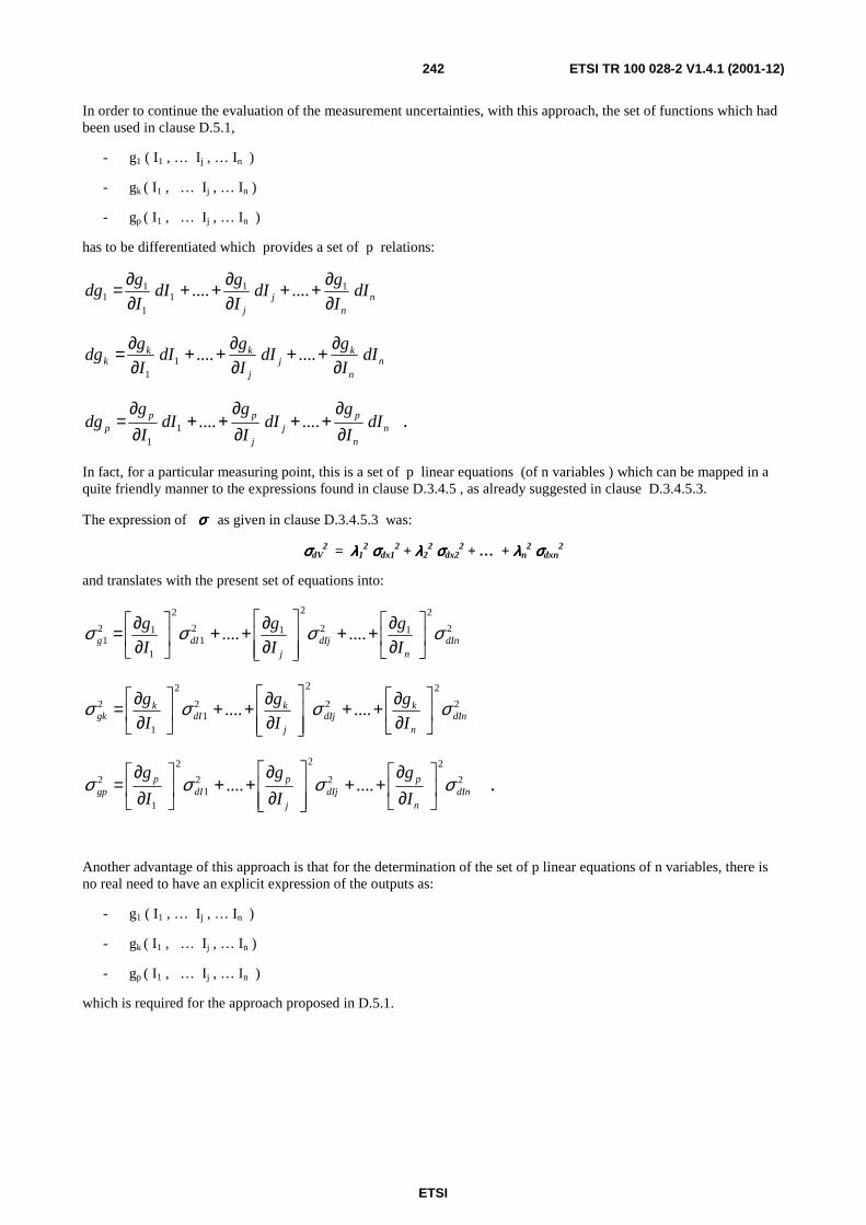
ETSI
ETSI TR 100 028-2 V1.4.1 (2001-12)242
In order to continue the evaluation of the measurement uncertainties, with this approach, the set of functions which had been used in clause D.5.1,
- g1 ( I1 , … Ij , … In )
- gk ( I1 , … Ij , … In )
- gp ( I1 , … Ij , … In )
has to be differentiated which provides a set of p relations:
nn
jj
dII
gdI
I
gdI
I
gdg
∂∂++
∂∂++
∂∂= 11
11
11 ........
nn
kj
j
kkk dI
I
gdI
I
gdI
I
gdg
∂∂++
∂∂++
∂∂= ........1
1
nn
pj
j
ppp dI
I
gdI
I
gdI
I
gdg
∂∂
++∂∂
++∂∂
= ........11
.
In fact, for a particular measuring point, this is a set of p linear equations (of n variables ) which can be mapped in a quite friendly manner to the expressions found in clause D.3.4.5 , as already suggested in clause D.3.4.5.3.
The expression of σσσσ as given in clause D.3.4.5.3 was:
σσσσdV2 = λλλλ1
2 σσσσdx12 + λλλλ2
2 σσσσdx22 + … + λλλλn
2 σσσσdxn2
and translates with the present set of equations into:
2
2
12
2
121
2
1
121 ........ dIn
ndIj
jdIg I
g
I
g
I
g σσσσ
∂∂++
∂∂++
∂∂=
2
2
2
2
21
2
1
2 ........ dInn
kdIj
j
kdI
kgk I
g
I
g
I
g σσσσ
∂∂++
∂∂++
∂∂=
2
2
2
2
21
2
1
2 ........ dInn
pdIj
j
pdI
pgp I
g
I
g
I
gσσσσ
∂∂
++
∂∂
++
∂∂
= .
Another advantage of this approach is that for the determination of the set of p linear equations of n variables, there is no real need to have an explicit expression of the outputs as:
- g1 ( I1 , … Ij , … In )
- gk ( I1 , … Ij , … In )
- gp ( I1 , … Ij , … In )
which is required for the approach proposed in D.5.1.

ETSI
ETSI TR 100 028-2 V1.4.1 (2001-12)243
It is, in the present approach (D.5.2 ), sufficient to find the expressions relating inputs and outputs, differentiate, and then resolve the linear equations in order to obtain:
- dg1
- dgk
- dgp .
It has finally to be noted that, in this approach, the output random variables can be matched directly to the estimation of the errors corresponding to measured values (probability of having the error within a certain interval), as opposed to clause D.5.1 where the output random variables would correspond to the probabilities of having a value of the measurement itself within a particular interval.
More precisely, the difference in interpretation (between D.5.1 and D.5.2) differs by a constant, which is the measured value. Therefore, calculations on sigmas ( σσσσ ) are the same when using either the approach given in D.5.1 or that given in D.5.2 …
D.5.3 Examples of application to particular cases
D.5.3.1 Using random variables together with differentiation in a measurement, case of multiplicative functions
In the case where the equations are multiplicative, the set of functions can be written as:
- g1 ( I1 , … Ij , … In ) = A1 ( I1 )b1 … ( Ij )
bj … ( In ) bn
- gk ( I1 , … Ij , … In ) = A2 ( ) ….
- gp ( I1 , … Ij , … In ) = … .
Then it becomes more convenient to use other type of expressions:
- either n
nn
j
jj I
dIb
I
dIb
I
dIb
g
dg ++++= ........1
11 (logarithmic differentiation)
- or … to transform the expressions into dBs.
The handling and understanding of these situations is similar to that of D.5.2 … with the exception that the random variables (and corresponding sigmas) can be mapped now to relative values, as opposed to absolute values in the approach given in D.5.2.
It has to be noted, however, that in approaches D.5.1 and D.5.2 random variables (and sigmas) have a unit (mA, Volts, etc) while in D.5.3 random variables (and sigmas) are relative, and have no real units (noting that values expressed in dBs are some kind of relative values).
D.5.3.2 Substitution measurements
Substitution measurements are often used in radio. It is expected by doing so, to reduce the influence of some parts of the set up, and their contribution in the uncertainty.
The methodology presented in clause D.5.1 is based on the handling of a set of p functions of n variables.
In the case of substitution measurements, the test set up for the measurement of radio systems can be modelled using two of these equations:
- one equation corresponding to the test set up "before" the substitution,
- one equation corresponding to the test set up "after" the substitution.

ETSI
ETSI TR 100 028-2 V1.4.1 (2001-12)244
The set of equations can therefore look like:
- g1 ( I1 , … Ij , … In )
- g2 ( I1 , … Ij , … In )
The practical handling and understanding of this set of two equations is similar to that corresponding to D.5.1 or D.5.2 (using differentiation) … with the exception that the random variables involved in the two equations are not necessarily independent …and that the aim of this method is to reduce the number of terms to be taken into account. This is usually done by calculating the equation corresponding to the difference (subtraction) of the two equations of the set.
It is therefore basic to identify:
- which inputs are in reality identical and appear in a way that they can be discarded (no contribution for the uncertainty, e.g. a cable which is used twice in the same conditions)
- which inputs (mapped to contributions of the uncertainty) are independent
- which inputs (mapped to contributions of the uncertainty) are not independent.
As a result of this analysis, some of the contributions are to be combined by RSSing, others disappear, others have to be combined in other ways (e.g. by linear combination as indicated in clause D.3.4.6) …
Substitution methods are often used for radio measurements because they are expected to provide better results. However, the analysis required for the evaluation of the corresponding uncertainties requires certainly more care than the analysis required in the case of direct measurements.
NOTE: This analysis has not necessarily been completed in all examples included in the present edition of the present document.
D.5.4 Empirical approach to find a model of the system When the equations are difficult to reach or to handle, it is possible for a complete system or for a part thereof (see clause D.5.5 , below) to try and find the equivalent of the partial derivatives (the coefficients needed in the linear equations addressed in clauses D.5.2 and possibly in D.5.3) by practical means.
Having the measurement set up operational for the measurement being considered, and having performed that measurement once, it is then possible to make "small" variations of the settings of the various instruments, in particular concerning the generators.
Such small differences (matching mathematically the dIj ) shall be:
- small enough so that the system being analysed can be considered as linear within that range ( + dIj )
- big enough to be large compared with the uncertainties of the measurement ("measurement noise")
- small enough so that equipment remains within the same operating range (e.g. the same scale for a voltmeter)
- made preferably both sides of the original setting ( Ij ) , in order to obtain directly + dIj .
The direct observation of the outputs of the system, would allow for a model to be established, providing the effect of the corresponding inputs (i.e. providing the values of the various coefficients corresponding to the
k
j
g
I
∂∂
of clause D.5.2).
In order to evaluate the random uncertainties in the set up, each time an input value is changed, it should be, for a while brought back to its initial value ( Ij ) , and the measurement performed again. In this way, there is a great number of evaluations of the measurand under nominal conditions, which gives a good visibility of the randomness associated with the set up. The knowledge of the dispersion of the results can be very helpful in order to choose how small should be the variations ("step sizes") in the settings of the various instruments (it is important to avoid taking noise for the effect of variations of the inputs!).

ETSI
ETSI TR 100 028-2 V1.4.1 (2001-12)245
Example of sequence of such steps:
- ( I1 , … Ij , … In )
- ( I1 + δδδδ , … Ij , … In )
- ( I1 , … Ij , … In )
- ( I1 - δδδδ , … Ij , … In )
- ( I1 , … Ij , … In )
- similar sequence for I2
- etc …until … In .
With 4 points per input variable … there are 4 n points to be measured. More points may be necessary if the effects are not linear.
Obviously, this procedure is supposed to cover only those parameters for which small variations are possible. This procedure can be very useful when the mathematical expression providing the effect of such inputs is difficult to obtain.
The evaluation of the effect of small variations of one variable (input) could be completed with the evaluation of the effects of changing simultaneously two or more inputs (e.g. for verification purposes, in particular for identification of variables which may interact) … as long as the interpretation of the corresponding results is fruitful.
Methods given in D.5.2 and D.5.3 could then be used, based on these empirical values found, or on an appropriate mix of values empirical and/or theoretical.
D.5.5 Splitting into sub-systems The aim of defining sub-systems is 3 fold:
- to keep equations within manageable sizes,
- to provide "building blocs" which could be used several times, without further mathematical work
(i.e. subsets common to different measurements),
- to support and simplify methods such as substitution methods, where parts of the set up are expected to be used twice.
When looking at the present document and its previous versions, it becomes clear that one of the major problems the present document had to cope with is the need, in radio measurements, to handle simultaneously electrical signals whose levels cover several orders of magnitude. Therefore, in some cases it is more practical to handle dBs, in others to handle linear terms. Clauses of annex D.3.8 and annex E show that besides very simple approximations (based on Log (1+x) = x) conversions in either directions are somewhat awkward and subject to discussion (e.g. to start with, questions such as "what are the basic shapes of the uncertainties, and in which domain" have to be answered).
The usage of sub-systems could, in some cases help this problem: an attempt could be made to isolate, in some sub-systems, parts to be handled in dBs, and, in other sub-systems, parts to be handled in linear terms, in an attempt to reduce the number of conversions (in particular conversions of uncertainties having values too large for simple approximations to be acceptable).
However, it has to be stated once again that all the analysis performed in clause D.3 (combination of random variables) were based on calculations on independent random variables. Therefore, to be in a position to use the tools developed so far, great care has to be taken so that there are not two variables inter-related in two different subsystems.
It can also be noted that empirical methods were proposed in clause D.5.4, in order to establish a model for a complete systems or parts thereof. Such possibilities may have also to be taken into account when tying to split systems into subsystems.
In the case of automated uncertainty evaluation systems, splitting in sub-systems could lead to concepts having a flavour of subroutines or even a flavour of object oriented systems.

ETSI
ETSI TR 100 028-2 V1.4.1 (2001-12)246
D.5.6 Presentation and interpretation of results obtained (outputs) The last paragraph(s) of clauses D.5.1 and D.5.2 have provided for an interpretation of the results obtained when combining in an appropriate manner the statistical/probabilistic properties of the "inputs" to the system being considered.
The purpose of clause D.5.6 is to provide a more general view on the topic and to go one step further, into the area of confidence levels.
Therefore, this clause starts with a classical approach, the "worst case" approach, and continues with the "probabilistic approach", which corresponds, in fact, to the "main stream" of the present document.
D.5.6.1 Worst case approach
This clause can be understood as part of an introductory clause to clause D.5.6.
In the "worst case approach", each contribution to the uncertainty is expected to be bound (which would not be the case for a probability density having a normal distribution).
In this approach, the evaluation of the uncertainty is based on the analysis of the situation where each variable would have had a value contributing to the "worst case" scenario.
In the case where all contributions correspond to rectangular distributions and are to be combined using an addition, then the "worst case approach" would provide the extreme points of the "foot-print" of the combined uncertainty (found in accordance with clauses D.3 and D.5), i.e. the interclause of the curve representing the distribution of combined uncertainty with the xx' axis (the horizontal axis).
D.5.6.2 Probabilistic approach
The " probabilistic approach" would rather focus on other properties of the combined uncertainty (e.g. its standard deviation or the shape of the corresponding distribution) than on "foot-prints", which is the focus of the "worst case approach".
D.5.6.2.1 Preliminary comments (and choice of scenario)
Clause D.5.6 and more particularly clause D.5.6.2 are intended to establish the relation between the results found when combining the various contributions to the uncertainty ("combined uncertainty") and the value to be provided as the result of the evaluation of the corresponding uncertainty.
As shown in clause D.5.6.1, in the case of the approach called "worst case approach", this is quite straight forward. It can be a little more complex in the case of the " probabilistic approach":
the "worst case approach" leads to the calculation of the value of a set of extreme points, while the "probabilistic approach" requires the understanding of the under-laying phenomena (and not only the RSSing of all the contributions).
The "probabilistic approach" triggers also new problems such as those related to the co-existence of expressions in linear terms and in dBs (in the case of the "worst case", should this happen, it is only necessary to calculate the two extreme points, so mixing dBs and linear terms is not a real problem, it only means that there are a few conversions to be performed).
Looking more in depth, it could be expected that the individual contributions to the measurement uncertainty are relatively small so that their conversions (dB into linear terms and vice-versa) are not a real problem (they can be performed using linear approximations). It is nevertheless important to make sure that the shape of the corresponding distribution has been correctly chosen (should the corresponding distribution have a rectangular shape, should it be rectangular in terms of dBs or in linear terms ?).
In the case of results of complete measurements, however, the combined uncertainty value may be quite large (see the table in annex B providing "the maximum uncertainty" values). For such high values (up to several dBs) significant differences may result from the way in which the conversions are handled (see, for example, clause D.3.8.4 and annex E). The example provided in clause D.3.7.4 shows clearly how much care is to be devoted to approximations…

ETSI
ETSI TR 100 028-2 V1.4.1 (2001-12)247
As a result, the following strategy can be proposed:
- to use rather simple conversion methods in order to perform the conversions relating to the various contributions (small values)
- to use more accurate methods when the values become higher (in particular final results of a measurement or final result of some "sub-system" (see the presentation of the sub-system concept in clause D.5.5)).
Among possible methods to make the conversions, can be quoted those presented in this annex (see D.3.8.4), those in annex E (presented differently, but equivalent (as indicated in clause D.3.8.4)); spread sheets can also be used, etc.
Attention has also to be drawn, again, to the fact that, during such conversions, familiar distributions, simple to describe in mathematical terms, are transformed in less familiar distributions (often having asymmetrical shapes and more complex to describe in mathematical terms) where the first moments (mean value, standard deviation) do not necessarily convey the expected information in a handy way ...and are not necessarily the images of the corresponding points (moments) before the conversion…
D.5.6.2.2 Summary of the methodology
The approach proposed in a number of detailed examples (given in annex D and in the main body of the present document as well) can be summarized as follows.
1) All the contributions for the uncertainty have to be identified (and the relations between the various parameters established).
2) The statistical/probabilistic properties (e.g. the standard deviations of the various contributions) have to be identified and appropriately combined together (see clauses D.5.1 and D.5.2 ).
If the combination corresponds to mere additions, then the situation is covered by the "BIPM method" and an RSSing of the various components can be performed.
3) Assuming that the appropriate combination of all contributions would result in a Gaussian shaped distribution, then the "combined uncertainty", characterized by its standard deviation, would be equal to the standard deviation of that Gaussian distribution.
This Gaussian would then represent, in fact (more precisely, in the case of the method given in clause D.5.2) the probability of error of the measurement (i.e. the uncertainty).
NOTE 1: In the case where the method provided in clause D.5.1 is used, the interpretation is similar, except that the resulting Gaussian would then correspond to measured values. Its mean value would then correspond to the result of the measurement (it could provide the "measured value").
4) A random variable E , the error of the measurement, corresponding to the above Gaussian distribution can be considered.
It is characterized (similarly to what has been written a number of times in the present annex) by the fact that its value x has a probability of occurrence given by the corresponding probability density e ( x ):
by definition, the probability Pe of the random variable E (the "error") having a value x such that
x1 < x < x2 is ∫=2
1
x
x
e e(x)dxP .
Similarly, we can consider ∫∞−
=x
e dte(t)xP )( ,
and therefore (by differentiation) dPe = e ( x ) dx .
5) When a certain set x1 , x2 is given, these bounds together with the shape of the Gaussian provide the probability of the error of the measurement being within those bounds.

ETSI
ETSI TR 100 028-2 V1.4.1 (2001-12)248
The equation of such a Gaussian is 2
2
2
2
1 σ
πσ
x
ey−
= , where σσσσ (sigma) is the standard deviation of the Gaussian
(and is equal to the combined uncertainty of the measurement), as shown in clause D.1.
When x = + σσσσ (sigma, the standard deviation), the corresponding values y1 and y2 are known, and the surface between the curve and the axis xx' (between + σσσσ (sigma)) can be found:
this surface provides the probability of the error being between + σσσσ (sigma), which is
∫+
−
=σ
σ
e(x)dxPe or
∫+
−
−=
σ
σ
σ
πσdxeP
x
e
2
2
2
2
1 .
This probability is equal to 68,3 % and provides the linkage to the confidence level.
6) As defined in TR 100 028-1 [6], clause 4.1.1:
absolute error = measured value - true value .
Therefore, when the probability of the absolute error being within + σσσσ is 68,3 % , then, the probability of the result of the measurement being within + σσσσ of the true value is also 68,3 % .
7) In order to have another (usually greater) confidence level, Pe' another set (therefore with wider values) x1' , x2' has to be found …
so that 2
1
'
'
'
x
e
x
P e(x)dx= ∫ .
The value of 1,96 has been given in the main body of the present document, as the multiplicative factor ("expansion factor") to be used in order to reach a confidence level of 95 %:
- when x1 = -1,96 x σσσσ
- and x2 = +1,96 x σσσσ ,
95,02
196,1
96,1
2 2
2
=∫+
−
−σ
σ
σ
πσdxe
x
, which is the sought confidence level.
This is true for any normal distribution (it is true for any Gaussian, independently of the value of σσσσ ), but true for normal distributions only.
An expansion factor of 2 can also be used:
2
22
2
2
10,9545
2
x
e dxσ
σ
σ σ π
+ −
−
=∫ .
An expansion factor of 2 provides therefore a confidence level of 95,45 %.

ETSI
ETSI TR 100 028-2 V1.4.1 (2001-12)249
NOTE 2: The values of
2
221
2
xk
k
e dxσ
σ
σ σ π
+ −
−∫ i.e. the values of the confidence levels corresponding to
an expansion factor k can be found easily in tables (such tables are often appended to books relating to probabilities (and providing properties of the Gaussians)).
D.5.6.2.3 Normal and non-Normal distributions
The principles given above are valid in all cases.
However, it is obvious that all numerical values, and in particular the actual values corresponding to "expansion factors " (i.e. 1,96 or 2 in the case of Gaussian distributions), are depending on the shape of the probability density resulting of the combination (i.e. the density probability of the error in case D.5.2) for a particular measurement.
An interesting example can be found in clause D.3.3.5.2.2.
Should the final probability density curve have a shape significantly different from a Gaussian, then the multiplicative factor (the "expansion factor") to get the 95 % confidence level would have to be re-evaluated, taking into account the actual probability density …(this kind of difficulty had already been identified in TR 100 028-1 [6], clause 6.6.5.1, where the direct usage of the expansion factor would have led to negative bit error ratios! )
That is why in clause D.3, not only the two first moments of the various combinations were evaluated, but were also provided the equations corresponding to the resulting probability densities themselves.
D.5.6.2.4 Confidence levels for non-Normal distributions
When having the expression of the resulting distribution e ( x ) , then the confidence level is given by the same expression as for normal distributions:
( )k
k
e x dxσ
σ
+
−∫ = confidence level corresponding to the expansion factor k .
However, for unusual expressions of e ( x ) , it is unlikely to find the corresponding values in tables … the corresponding calculations will therefore have to be made on a case by case basis.
Further comments
1) In one of the examples given in annex D (in clause D.3.3.5.1), it is shown that the result of the additive combination of two Gaussian shaped uncertainties (i.e. random variables) is also a Gaussian shaped uncertainty (i.e. random variable).
In this respect Gaussians are stable (rectangular distributions are not: the combination of two identical rectangular distributions is a triangular distribution, as shown in clause D.1.3.2).
2) Converting dBs into linear and vice-versa, tends to generate asymmetric distributions … and this may have to be duly taken into account. An attempt to give some properties of asymmetrical distributions has been made in clause D.1.3.3 (trapezoidal) and D.1.3.5 , but calculations with such expressions are not always that easy. Handling such expressions is an area where approximations can be used extensively.
Symmetrical expansion factors can be used in all cases, but when distributions are asymmetric, it can also be thought of using asymmetric expansion factors (one for expanding the lower bound and another for expanding the upper bound)…
Another proposal had been made in the first days of ETR 028 [5]:
to calculate both a "sigma plus" and a "sigma minus" … as if the final error distribution was composed of 2 half Gaussian distributions:
2
2
2
2
1 σ
πσ
x
ey−
= with two values for sigma, one when x is positive and another when x is negative.

ETSI
ETSI TR 100 028-2 V1.4.1 (2001-12)250
… one trouble with such a representation is that the 2 distributions do not necessarily fit together in 0:
πσ 2
1)0( =y , which shows that y ( 0 ) depends on σσσσ (sigma).
Therefore e ( 0 + ) ≠≠≠≠ e (0 -)
and e ( 0 + ) dx ≠≠≠≠ e (0 -) dx
finally ∫+
+ =ε
ε0
)( e(x)dxP ≠≠≠≠ ∫−
− =0
)(ε
ε e(x)dxP
which does mean that the probability of having a range of very small positive errors is significantly different from that of having a very small range of negative errors … not very satisfactory!
The way to handle the uncertainties in the present version of the present document seems more satisfactory.
3) It can also be noted that a finite sum of distributions having a finite footprint has also a finite footprint.
As a result, in such a situation, there should be an expansion factor providing a 100 % confidence.
4) clause D.3.3.5.2 has highlighted a case where a non finite sum of rectangular shaped distributions has provided a finite footprint. In such case, there should also be an expansion factor providing for a 100 % confidence level.
5) In the case where a "worst case" (see clause D.5.6.1) value exists …then there should also be an expansion factor providing a 100 % confidence level.
D.5.6.2.5 Practical conclusions
As a result, and in order to avoid extensive discussion, results could be presented:
- as a "1.96 x σσσσ (sigma)" value
- or as a "95 % confidence level" value,
with a note stating that the two values are equivalent in the case of normal distributions.
This should replace text such as:
"The expanded uncertainty is ± 1,96 × 1,06 dB = 2,07 dB at a 95 % confidence level",
which has also been used for cases where there is no evidence that the distribution concerned is normal (the number (and relative weight) of contributions combined in many evaluations of the measurement uncertainty may not be sufficient for the central limit theorem to be valid).
NOTE: As shown above, the method to be used when changing the confidence level can be justified by the properties of the distribution obtained when combining the various contributions in order to obtain the combined uncertainty, in particular, when a Gaussian distribution is obtained.
There is no need to use the t-Student theory (which is valid only when normal distributions are handled)…and which relates to statistics (e.g. series of measurements).
D.5.6.2.6 Implications
Corresponding changes in text should therefore be introduced in a numbers of places (including in a number of clauses of the present document).
In a report relating to measurements, should be found:
- the measured value;
- the uncertainty value found;

ETSI
ETSI TR 100 028-2 V1.4.1 (2001-12)251
- a statement indicating that:
- this uncertainty value corresponds to "a confidence level of 95 %" or
- this uncertainty value corresponds to "1.96 x σσσσ (sigma)"
(where 95 % and 1,96 are the values used in the main body of the present document)
- and a note indicating that "1.96 x σσσσ (sigma) is equivalent to a confidence level of 95 % in the case where distributions are normal".
NOTE: An expansion factor of 2 is also acceptable. It corresponds to a confidence level of 95,45 %. In this case, the statements above should be amended accordingly.
D.5.6.2.7 Examples (excerpts from available standards)
ETSI has been drafting technical standards in support of a variety of radio equipment, and also a number of standards to be harmonized under Directives, such as the R&TTE Directive.
The following excerpts were taken from:
- Part 1 (corresponding to "the radio product standard"); and
- Part 2 (corresponding to "the candidate harmonized standard") of the standard corresponding to one particular product.
This material, provided as an example, shows how the words proposed above (in clause D.5.6.2.6) have been used in recent standards prepared by ETSI.
A third example shows how double sided limits have been handled in TR 100 028-1 [6] of a standard relating to integral antenna equipment (in the clause relating to limits).
D.5.6.2.7.1 Excerpts from a "Part 1"
"
11 Measurement uncertainty
Table D.1: Absolute measurement uncertainties: maximum Values
Parameter Uncertainty Radio Frequency ±1 x 10⁻⁷ RF Power (up to 160 W) ±0,75 dB Radiated RF power ±6 dB Adjacent channel power ±5 dB Conducted spurious emission of transmitter Valid up to 12,75 GHz
±4 dB
Conducted spurious emission of receiver, Valid up to 12,75 GHz
±7 dB
Two-signal measurement, Valid up to 4 GHz ±4 dB Three-signal measurement ±3 dB Radiated emission of the transmitter, valid up to 4 GHz
±6 dB
Radiated emission of receiver, valid up to 4 GHz
±6 dB
Transmitter attack time ±20 % Transmitter release time ±20 % Transmitter transient frequency (frequency difference)
±250 Hz
Transmitter intermodulation ±3 dB Receiver desensitization (duplex operation) ±0,5 dB Valid up to 1 GHz for the RF parameters unless otherwise stated.

ETSI
ETSI TR 100 028-2 V1.4.1 (2001-12)252
For the test methods, according to the present document, the measurement uncertainty figures shall be calculated in accordance with TR 100 028 and shall correspond to an expansion factor (coverage factor) k = 1,96 or k = 2 (which provide confidence levels of respectively 95 % and 95,45 % in the case where the distributions characterizing the actual measurement uncertainties are normal (Gaussian)).
Table D.1 is based on such expansion factors.
The particular expansion factor used for the evaluation of the measurement uncertainty shall be stated.
"
NOTE: the table of "Absolute measurement uncertainties" is included here just for completeness. The "standard table" can be found in annex B of the present document.
D.5.6.2.7.2 Excerpts from a "Part 2"
"
5.2 Interpretation of the measurement results
The interpretation of the results recorded in a test report for the measurements described in the present document shall be as follows:
- the measured value related to the corresponding limit will be used to decide whether an equipment meets the requirements of the present document;
- the value of the measurement uncertainty for the measurement of each parameter shall be included in the test report;
- the value of the measurement uncertainty shall be, for each measurement, equal to or lower than the figures in table D.2.
For the test methods, according to the present document, the measurement uncertainty figures shall be calculated in accordance with TR 100 028 and shall correspond to an expansion factor (coverage factor) k = 1,96 or k = 2 (which provide confidence levels of respectively 95 % and 95,45 % in the case where the distributions characterizing the actual measurement uncertainties are normal (Gaussian)).
Table D.2 is based on such expansion factors.
The particular expansion factor used for the evaluation of the measurement uncertainty shall be stated.
Table D.2: Absolute measurement uncertainties: maximum values
Parameter Uncertainty Radio Frequency ±1 X 10⁻⁷ RF Power conducted (up to 160 W) ±0,75 dB Conducted RF Power variations using a test fixture ±0,75 dB Radiated RF power ±6 dB Adjacent channel power ±5 dB Average sensitivity (radiated) ±3 dB Two-signal measurement, valid up to 4 GHz (using a test fixture) ±4 dB Two-signal measurement using radiated fields (see note) ±6 dB Three-signal measurement (using a test fixture) ±3 dB Radiated emission of the transmitter, valid up to 4 GHz
±6 dB
Radiated emission of receiver, valid up to 4 GHz
±6 dB
Transmitter transient frequency (frequency difference) Transmitter transient time
±250 Hz ±20 %
Values valid up to 1 GHz for the RF parameters unless otherwise stated. NOTE: For blocking and spurious response rejection measurements.
"

ETSI
ETSI TR 100 028-2 V1.4.1 (2001-12)253
NOTE: the table of "Absolute measurement uncertainties" is included here just for completeness. The "standard table" can be found in annex B of the present document.
D.5.6.2.7.3 Excerpts from a "Part 1" showing words used for double sided limits
The following piece of text shows one way to adapt the "shared risk approach" to the case where the measurement uncertainties are larger than the allowed tolerances. Should such a case happen, the direct implementation of the "shared risk approach" could have resulted in a situation where good equipment might have failed the test.
"
5.1.2.1 Effective radiated power under normal test conditions
The maximum effective radiated power under normal test conditions shall be within df of the rated maximum effective radiated power.
…/…
The allowance for the characteristics of the equipment (±1,5 dB) shall be combined with the actual measurement uncertainty in order to provide df, as follows:
df2 = dm
2 + de2;
where:
- dm is the actual measurement uncertainty;
- de is the allowance for the equipment (±1,5 dB);
- df is the final difference.
All values shall be expressed in linear terms.
In all cases the actual measurement uncertainty shall comply with clause 10.
Furthermore, the maximum effective radiated power shall not exceed the maximum value allowed by the administrations.
Example of the calculation of df:
- dm = 6 dB (value acceptable, as indicated in the table of maximum uncertainties, table 8);
= 3,98 in linear terms;
- de = 1,5 dB (fixed value for all equipment fulfilling the requirements of the present document);
= 1,41 in linear terms;
- df2 = [3,98]2 + [1,41]2;
therefore df = 4,22 in linear terms, or 6,25 dB.
This calculation shows that in this case df is in excess of 0,25 dB compared to dm, the actual measurement uncertainty (6 dB).
"
Comment: In the present document, it was chosen to combine the two components in linear terms. It could have been decided, as well, to do the operation in dBs. See the corresponding discussion in clause D.5.6.2.1.

ETSI
ETSI TR 100 028-2 V1.4.1 (2001-12)254
D.5.6.2.8 Confidence levels and single sided limits
The confidence level has been related to
∫=2
1
x
x
e e(x)dxP , the probability of the value x of the random variable E being so that x1 < x < x2 .
In the case where L is a limit value (single sided), and V the true value of the measurand, then the probability of having good equipment failing the test is such as:
fail
L V
P e(x)dx∞
+−
= ∫ or V L
failP e(x)dx−
−∞
= ∫ as appropriate (depending on the relative position of the sought
value, V , in relation to L ).
In the particular case when the distribution is, in fact, a normal distribution, and when the true value of the measurand is at 1.96 x σσσσ (sigma) from the limit L , then the expression of the probability of having good equipment failing the test is such as:
2
22
1,96
1
2
x
failP e dxσ
σ σ π
+∞ −= ∫ = 0,5 ( 1 – 0, 95) = 0,025.
It can be noted, however, that, as already suggested, in the case of radio measurements, finite sums of finite distributions are often found. Therefore, it is far from being sure that the Gaussian model is suitable for the discussion of effects far away from the area -σ σ σ σ to +σ σ σ σ , such as the probability of failing good equipment …
It is quite likely that, in many cases, by increasing the expansion factor, the "worst case" value is reached, while, with the Gaussian model, there is always a (remote) probability to fail a good unit.
The safe approach to calculate the probability of failing good equipment is certainly to calculate the actual distribution first, and then to use expressions such as those given in the beginning of the present clause, in order to calculate the appropriate probabilities.
D.5.6.3 Conclusions
Clause D.5.6 has provided an overview of the usual ways of addressing uncertainties:
- the "worst case" approach and
- the "probabilistic" approach.
It has also covered the relations between these approaches as well as methods and caveats relating to the evaluation of the corresponding "confidence levels".
Finally, it has also proposed methods to calculate correctly the probability of failing good equipment.
D.5.7 Summary Clause D.5 has provided a set of approaches and methods that should cover the evaluation of measurement uncertainties and their confidence levels in a most situations (and can also cover applications far beyond the scope of the present document).
The majority of the clause in D.5 address however, implicitly, the case where differentiation is used (clause D.5.2). But most concepts are usable also without differentiation (clause D.5.1); in some cases a slight transposition may have to be performed by the reader (trying to cover fully and individually, in this clause all possible combinations of methods and approaches could have resulted in an unnecessarily bulky clause…).

ETSI
ETSI TR 100 028-2 V1.4.1 (2001-12)255
Clause D.5 provide, in fact, the basis for the various clauses of the present document (i.e. the "examples"), even though, in the majority of cases only the handling of the "sigmas" (standard deviations) has been described (while forgetting quite often to provide the underlying physical equations and to discuss which variables are independent and which are not)… an area which could be enhanced in future editions.
D.6 Conclusions Annex D has provided general methods based upon the analysis of complex systems and a number of tools (e.g. in clause D.3) allowing to evaluate the measurement uncertainties related to the various measurement set up. It has in particular provided support for a number of clauses of both Part 1 and 2 of the present document, as well as highlighted precautions in order to avoid fundamental errors while using the examples developed over the various clauses (e.g. special attention to the independence (or possible inter-dependence) of the various associated random variables).
When drafting this annex, the new situation in Europe, originated by the implementation of the R&TTE was also in mind: it is likely that in the future, with concepts such as self-declaration or self-certification, many more partners will have to make and understand radio measurements … and to handle the corresponding measurements uncertainties (hopefully in the same way). Therefore, new text was written in an attempt to make the present document as much self contained as practical, including all the theoretical elements allowing for any laboratory to understand what is to be done and obtain correct values, while giving any one a chance to try and find solutions well adapted to his own measurement set up …
It is also expected that many other types of systems might be analysed using the methods developed in this annex.
It can be noted, for example, that a number of mobile systems use adaptive techniques, such as power control. Such techniques are usually, in one way or another, based upon measurements (made by the mobiles and/or by base or monitoring stations).
The methods presented in this annex could certainly be helpful also when evaluating the influence of the measurement uncertainties relating to such (simple) measurements, on the performance of the modern mobile systems where such features are implemented. Among possible effects of such uncertainties can be quoted loss of system capacity, signalling overhead … or even system oscillations …
Measurement uncertainties (as well as dispersion of equipment characteristics) may also have to be taken into account in studies relating to the compatibility between systems, systems lay out, etc …

ETSI
ETSI TR 100 028-2 V1.4.1 (2001-12)256
Annex E: Mathematical transforms This annex shows how direct methods can be used to transform distributions. Other methods (more general methods) for transforming (or converting) distributions are presented in clause D.3.9.
E.1 Principles of derivation of formulas when transforming from log to linear
When transforming from one co-ordinate system to another the following apply:
1) The probability of an event being within an interval is the same no matter which scale on the co-ordinate system you look at:
A B
dB %
A / B /
A /% dBA B /% dBB
p x1 ( ) p x2 ( )
∫∫ =/
/
B
A
B
A
)dx(xp(x)dxp 1121
2) this also means that:
11121 == ∫∫+∞
∞−
+∞
∞−)dx(xp(x)dxp
3) based on this, the converted distribution can now be derived.
E.1.1 A rectangular distribution in logarithmic terms converted to linear terms
In this example a rectangular distribution in logarithmic terms is converted to linear terms:
-A +A
12A
x1 x2 0dB
p x( )
AA x A
x
= − ≤ ≤
=
1
20
for
for all other values of p x( )
p x( )| |

ETSI
ETSI TR 100 028-2 V1.4.1 (2001-12)257
The probability of x being in the interval between x1 and x2 is:
−=∫ 12 2
1
2
1
2
12
1
xA
xA
dxA
x
x
;
( )122
1xx
A−= .
In log terms. Therefore in linear terms this becomes:
( ) ( )12
10
10
12 2
1202
201
xxA
dxxp
x
x
−=∫ ;
−
= 20
220
2
12
1010
xx
PP ;
where ( ) ( )∫= xpxP 22 or in other words A
xP
x
210 220
2
2
=
.
Substituting 102 LogKP /= gives:
A
xxKLogK /
x/
22010 2220
10
2
==
;
A
K / 10= ;
( ) ( ) ( )xLnA Ln
xLogA 10
101010 = ;
( )
x=
dx
xdLnAs
1;
( ) ( ) x
A Lnxp
1
10
102 = .
1 A
2010
A
2010−
P2 (x)
From p2(x) the mean value xm and the standard deviation can be found.

ETSI
ETSI TR 100 028-2 V1.4.1 (2001-12)258
General formula:
dxxxpxm )(2∫= ;
∫∫ ==C
B
C
Bm K dxx dx
xKx
1 ;
[ ] ( )C-B=KKxx CBm = .
where ( )2020 1010
10
10AA
; C ; BA Ln
K ===−
.
Then the standard deviation σ can be found. The general formula is:
( ) ( )dxxpxxs m∫+∞
∞−
−= 22 ;
( ) dxx
Kxxs
C
B
m∫ −= 122 ;
( ) dxx
Kxxxx
C
B
mm∫ −+= 222 ;
dxKxKxx
KxC
B
mm∫
−+= 2
2
;
( )C
B
mm KxxKx
xLnKx
−+= 2
2
22 ;
( ) ( ) ( ) ( )
−−−+− BCxBCBLnCLnxK mm 22
1 222 ;
( ) ( )( ) 1=− BLnCLnAs K .
Therefore:
( ) ( )2222
2
12 BCKBCKxxs mm −+−−= ;
and ( )BCKxm −= hence:
( ) ( ) ( )2222222
2
12 BCKBCKBCKs −+−−−= ;
( ) ( )2222
2
1BCKBCK −−−= ;
therefore:
( ) ( )222250 BCKBCK,s −−−= .
This procedure can (in principle) be applied to any conversion of any distribution. See also clause D.3.9 where a general approach is provided.

ETSI
ETSI TR 100 028-2 V1.4.1 (2001-12)259
E.1.2 A triangular distribution in logarithmic terms converted to linear terms
In the same way as with the rectangular distribution the conversion from logs to linear terms are made:
dBx1 x2
A
1
A+A−
p xA
A x x A
p xA
A x A x
p x x
1 2
1 2
1
10
10
0
( )
( )
( )
= + > ≥ −
= − ≥ ≥
=
||||||
||||||
for
for
for all other values of
p x1 ( )
In the negative interval:
( )2
1
2
1
2
1
2
2
212
1x
x
x
x
x
xA
x
A
x dx
A
x
A dxxp
+=
+= ∫∫ ;
−
=
+−+ 20
220
22
211
2
222
12
101022
xx
PP A
x
A
x
A
x
A
x;
2
220
22
10A
x
A
x P
x
+=
.
Solution:
( ) ( )( )221 yLogKyLogK + ;
A
x=
xKLogK
x
2010 1
201 =
;
A
K20
1 = ;
2
22
202
210
A
x=LogK
x
;
2
2
2
2
2220 A
x=
xK ;
212
2
2 2
1
2
20K=
AK = .
Logs converted to Ln:
( )10
201 A Ln
K = ;
( ) ( ) ( )( )22112 2
1yLnKyLnKyP += ;

ETSI
ETSI TR 100 028-2 V1.4.1 (2001-12)260
( ) ( )
y
yLnK
yK
dy
ydP 211
1 += ;
( )y
yLnK
yK 2
111 + for 110 20 ≤≤
−
y
A
; and
( )y
yLnK
yK 2
111 − for 20101
A
y ≤≤ ;
2020 1010
AA
and CB ==−
.
Mean value:
( ) ( )
∫∫
−+
+=C
B
m xdxdx
xLnK
xKxdx
dx
xLnK
xKx
1
211
1211
11;
( )( ) ( )( )∫∫ −++=C
B
dxxLnKKdxxLnKK
1
211
1211 ;
( ) ( )∫∫∫ −+=C
B
C
B
dxxLnKdxxLnKK
1
21
1211 ;
[ ] ( )[ ] ( )[ ]CB
CB xxxLnKxxxLnKxK 1
21
1211 −−−+= ;
( ) ( )( ) ( )( ) 11 21
21
21
211 kCCC LnKBBB LnK KBCK −−−−−+−= ;
( )
−−
−−−−−= 1
11
12
1
21
1
21
211 k
cKk
BKKBCK ;
( ) CKCKBKBKKBCK 211
211
211 2 +−×++−−= ;
( )221 −+= CBKxm .
Standard deviation:
( )∫+∞
∞−
−= p(x)dxxxs m22 ;
( ) ( ) ( ) ( )dx
x
xLnK
xKxxdx
x
xLnK
xKxx
C
m
B
m ∫∫
−−+
+−=1
211
21
211
2 11;
( ) ( ) ( ) ( ) ( )∫∫∫ −−−+−=C
m
B
m
C
B
m dxx
xLnKxxdx
x
xLnKxx
xKxx
1
21
21
21
21
2 1;
( ) ( ) ( ) ( ) ( )∫∫∫ −+−−++−+=C
mm
B
mm
C
B
mm dxx
xLnKxxxxdx
x
xLnKxxxx
xxxxxK
1
21
221
21
22221 22
12 ;

ETSI
ETSI TR 100 028-2 V1.4.1 (2001-12)261
( ) ( ) ( ) ( ) ( ) ( )∫∫∫
−+−
−++
−+=
C
mm
B
mm
C
B
mm dxxLnxxxLn
x
xLnxKdxxLnxxxLn
x
xLnxKdxKxxK
x
Kx
1
221
122
1111
2
222 ;
( ) ( )
−=∫ 22
4
1
2
1xxLnxxxLn ;
( )
( )( ) ( ) ( )( )
( )( ) ( ) ( )( )C
mm
Bmm
C
Bmm
xxxLnxxLnxxLnxK
xxxLnxxLnxxLnxK
xxxxLnxK
1
22221
12222
1
221
22
1
2
1
2
1
22
1
2
1
2
1
22
1
−−
−+−
−−
−++
−+=
;
( ) ( )( ) ( ) ( )
( ) ( )( ) ( ) ( )( )
( )( ) ( ) ( )( )
−+−−
−+−
−+
−−−−−
−+
−−−+−=
mmm
mmm
m
xCCCLnxCLnCCLnxK
BBBLnxBLnBBLnxxK
BCxBCBLnCLnmK
24
12
2
1
2
1
2
1
22
1
2
1
2
112
2
1
2
1
22
1
22221
22221
2221
;
( ) ( )( ) ( ) ( )
−===−
111
111
KB, Ln
KC, LnBLncLnK ;
( ) ( ) 22221 2
4
1
2
14 mmm xCBxCBxK +
+−++−= ; and
( ) ( ) 22221 2
4
1
2
14 mmm xCBxCBxKs +
+−++−= .
E.1.3 A rectangular distribution in linear terms converted to logarithmic terms:
In this example a rectangular distribution in linear terms is converted in to logarithmic terms:
x1 x2
p x( )
B C1
C B1
B A1
C A1
KA
1
21
Linear
( )∫∫ =2
1
2
1
20
2021
Log x
Log x
x
x
dyyp dxK ;
( ) ( ) ( )12221122 2020 Log xp Log xpxKxK −=− .
In other words: ( )( )x LogpXK 2021 = , the solution: ( ) xK=Kxp 21032 where
==20
12K ( )
1320
3111210 xKKxK xLogK == Now ( ) ( )xLnKxK eK Kx pKK 10
332132210 === .
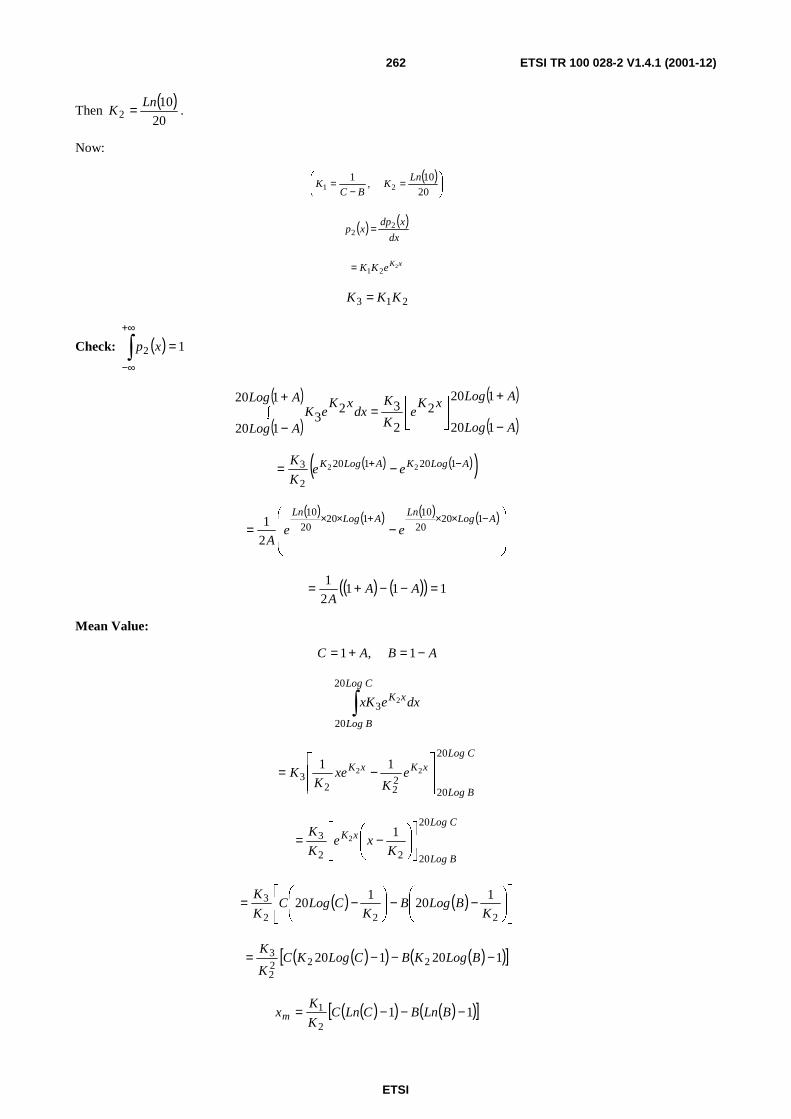
ETSI
ETSI TR 100 028-2 V1.4.1 (2001-12)262
Then ( )
20
102
LnK = .
Now:
( )
=−
=20
10121
Ln, K
BCK
( ) ( )dx
xdpxp 2
2 =
xKeKK 221=
213 KKK =
Check: ( ) 12 =∫+∞
∞−
xp
( )
( )
( )
( )ALog
ALog
xKe
K
KALog
ALogdx
xKeK
+
−
=∫+
−
120
120
2
2
3120
120
23
( ) ( )( )ALogKALogK eeK
K −+ −= 120120
2
3 22
( ) ( ) ( ) ( )
−=
−××+×× ALogLn
ALogLn
eeA
12020
10120
20
10
2
1
( ) ( )( ) 1112
1 =−−+= AAA
Mean Value:
AA, BC −=+= 11
∫Log C
Log B
xK dxexK
20
20
32
Log C
Log B
xKxK eK
xeK
K
20
20222
322
11
−=
Log C
Log B
xK
Kxe
K
K20
2022
3 12
−=
( ) ( )
−−
−=
222
3 120
120
KBLogB
KCLogC
K
K
( )( ) ( )( )[ ]120120 2222
3 −−−= BLogKBCLogKCK
K
( )( ) ( )( )[ ]112
1 −−−= BLnBCLnCK
Kxm

ETSI
ETSI TR 100 028-2 V1.4.1 (2001-12)263
Standard deviation
( ) ( )dxxpxxs m∫ −= 22
( )( )
( )
∫=+
=−
−+=EALog
DALog
xKmm dxeKxxxxs
120
120
3222 22
E
D
xK
E
D
xKE
D
xKm
Kxe
K
Km
KK
xxe
K
Ke
K
Kx
−−
−−+
=
22
3
222
2
2
3
2
32 1222
222
Now ∫
+=K
xeK
xe KxKx 11 and ∫
+−=
222 221
KK
xxe
Kex KxKx and 1
2
3 KK
K=
( ) ( )
−−−−
−−++
++= Dx
K
DDAEx
K
EEA
K
x
KxAKs mm
mm 2
212
21
222
2
2
2
2
222
21

ETSI
ETSI TR 100 028-2 V1.4.1 (2001-12)264
E.2 Conversion factors
0
1020304050607080
0,5
11,
52
2,5
33,
54
4,5
5
Tria
ngul
ar lo
g to
line
arU
-Dis
trib
utio
n lo
g to
line
ar
Rec
tang
ular
log
to li
near
Gau
ssia
n lo
g to
line
ar
Figure E.1: Standard deviations

ETSI
ETSI TR 100 028-2 V1.4.1 (2001-12)265
Figure E.1 shows that if the standard deviation of a distribution in logarithms is smaller than 2,5 dB to 3,0 dB (resembling errors in the region of 5 dB to 6 dB), the following formula is a good approximation: ujlin = 11,5 × ujlog.

ETSI
ETSI TR 100 028-2 V1.4.1 (2001-12)266
Annex F: Influence quantity dependency functions Table F.1 is a list of influence quantity dependency functions and uncertainties that are dependant on the equipment under test only. They are nevertheless necessary for the calculation of the absolute measurement uncertainty.
The table contains three types of parameters:
- reflection coefficients for the calculation of mismatch uncertainty;
- dependency factors for the conversion from influence quantity uncertainty to uncertainty related to the measurand;
- additional uncertainty caused by influence quantities.
The test laboratory making the measurements may, by means of additional measurements, estimate its own influence quantity dependencies, but if this is not carried out the values stated in table F.1 should be used.
Table F.1 is based on measurements on a variety of equipment types. Each dependency is expressed as a mean value with a standard deviation reflecting the variation from one EUT to another. Some dependencies related to the general test conditions (supply voltage, ambient temperature, etc.) theoretically influence the results of all the measurements, but in some of the measurements they are so small that they are considered to be negligible.
The table is divided into sub tables relating to the measurement examples described in clause 7 of TR 100 028-1 [6] (transmitter examples) and clause 4 of the present document (receiver examples). The corresponding clause numbers are shown in brackets.
Table F.1: EUT-dependency functions and uncertainties
Mean Standard deviation Frequency error (see clause 7.1.1 of TR 100 028-1 [6]) Temperature dependency
0,02
0,01 ppm/°C
Carrier power (see clause 7.1.2 of TR 100 028-1 [6]) Reflection coefficient Temperature dependency Time-duty cycle error Supply voltage dependency
0,5 4,0 % 0 10
0,2 1,2 %/°C 2 % (p) 3 % (p)/V
Frequency deviation (see clause 7.1.9 of TR 100 028-1 [6]) Temperature dependency
0,02
0,01 ppm/°C
Adjacent channel power (see clause 7.1.3 of TR 100 028-1 [6]) Deviation dependency Filter position dependency Time-duty cycle error
0,05 15 0
0,02 % (p)/Hz 4 dB/kHz 2 % (p)
Conducted spurious emissions (see clause 7.1.4 of TR 100 028-1 [6]) Reflection coefficient Time-duty cycle error Supply voltage dependency
0,7 0 10
0,1 2 % (p) 3 % (p)/V
Intermodulation attenuation (see clause 7.1.5 of TR 100 028-1 [6]) Reflection coefficient Time-duty cycle error Supply voltage dependency
0,5 0 10
0,2 2 % (p) 3 % (p)/V
Transmitter attack/release time (see clauses 7.1.6 and 7.1.7 of TR 100 028-1 [6]) Time/frequency error gradient Time/power level gradient
1,0 0,3
0,3 ms/kHz 0,1 ms/%
Measured usable sensitivity (see clause 4.1.1 of the present document) Reflection coefficient Temperature dependency Noise gradient (below the knee point) Noise gradient (above the knee point) Noise gradient (direct carrier modulation)
0,2 2,5 0,375 1,0 1,0
0,05 1,2 %/°C 0,075 % level/% SINAD 0,2 % level/% SINAD 0,2 % level/% SINAD

ETSI
ETSI TR 100 028-2 V1.4.1 (2001-12)267
Mean Standard deviation Amplitude characteristic (see clause 4.1.8 of the present document) Reflection coefficient RF level dependency
0,2 0,05
0,05 0,02 %/% level
Two signal measurements (see clauses 4.1.2, 4.1.3, 4.1.4 and 4.1.6 of the present document) Reflection coefficient (in band) Reflection coefficient (out of band) Noise gradient Deviation dependency Absolute RF level dependency
0,2 0,8 0,7 0,05 0,5
0,05 0,1 0,2 % level/% SINAD 0,02 %/Hz 0,2 %/% level
Intermodulation response (see clause 4.1.5 of the present document) Reflection coefficient Noise gradient (unwanted signal) Deviation dependency Capture ratio dependency
0,2 0,5 0,05 0,1
0,05 0,1 % level/% SINAD 0,02 %/Hz 0,03 %/% level
Conducted spurious emission (see clause 4.1.7 of the present document) Reflection coefficient Supply voltage dependency
0,7 10
0,1 3 %/V
Desensitization (Duplex) (see clause 5.2 of the present document) Reflection coefficient Temperature dependency Noise gradient (below the knee point) Noise gradient (above the knee point) Noise gradient (direct carrier modulation)
0,2 2,5 0,375 1,0 1,0
0,05 1,2 %/°C 0,075 % level/% SINAD 0,2 % level/% SINAD 0,2 % level/% SINAD
Spurious response rejection (Duplex) (see clause 5.1 of the present document) Reflection coefficient (pass band) Reflection coefficient (stop band) Noise gradient Deviation dependency Absolute RF level dependency
0,2 0,8 0,7 0,05 0,5
0,05 0,1 0,2 % level/% SINAD 0,02 %/Hz 0,2 %/% level

ETSI
ETSI TR 100 028-2 V1.4.1 (2001-12)268
Annex G: Mismatch uncertainties
G.1 Introduction Mismatch uncertainties are calculated in the present document using S-parameters.
A two-port network connects a generator and a load with reflection coefficients ρG and ρL respectively. Input and
output wave amplitudes a1 and a2, b1 and b2 exist at the planes shown in figure G.1. The performance of this two-port
network can be specified in terms of four complex quantities known as S-parameters where:
b1 = S11a1 + S12a2
b2 = S21a1 + S22a2
LoadTwo-portρ
Gρ
L
1a a2
b21b
Figure G.1: Two-port network
The corresponding matrix of the network can be described by an S-parameter (S for scattering) matrix:
=
2221
1211
SS
SSS
Where S11 is the complex reflection coefficient at port 1 when port 2 is perfectly terminated (and vice versa). S21 is the complex transmission coefficient (or gain) from port 1 to port 2 when both ports are perfectly terminated (and vice versa). For passive, linear networks S21 = S12.
From the definition of S parameters it is easy to see that mismatch loss is covered by the transmission coefficients. In other words it is of no importance whether the attenuation of a network is caused by power dissipation in the network or by reflection at the input.
To illustrate this consider an ideal filter (ideal means it is lossless). All of the filtering is due to reflections at the input, as in an ideal filter, no power can be dissipated inside itself. Therefore if a loss (or gain) has been measured, the mismatch loss has already been taken into account and only the mismatch uncertainty remains. Therefore no correction due to mismatch loss is required.
G.1.1 Cascading networks If two networks are cascaded (see figure G.2) the resulting network S-parameter matrix is a combination of the two original S-parameters. First each individual S-parameter matrix must be transformed to a T-matrix (T for transformation)
=
Stde- S
-S
ST
11
22
21
11
Where det S is the determinant of S.
Then the resulting T matrix is calculated.

ETSI
ETSI TR 100 028-2 V1.4.1 (2001-12)269
For example:
Network C
NetworkA
NetworkB
Figure G.2: Cascading networks
S-parameters:
=
2221
1211
AA
AAA SS
SSS
=
2221
1211
BB
BBB SS
SSS
Which gives:
=
2221
1211
AA
AAA TT
TTT
=
2221
1211
BB
BBB TT
TTT
The T-matrix for the resulting (combined) network (c) is then:
TC = TATB
=
2221
1211
2221
1211
BB
BB
AA
AABA TT
TT
TT
TTTT
=
2222122121221121
2212121121121111
BABABABA
BABABABA
T + TTTT + TTT
T + TTTT + TTT
From the resulting TC back to S parameters:
=
12
21
11 1
1
- T
t T-deT
TS .
From these general methods some useful formulas can be derived:
Applying the methods on the two A and B, TA is found:
=
AA
A
AA Stde- S
- S
ST
11
22
21
11 ;
+=
2112221111
22
21
11
AAAAA
A
A SSS- SS
- S
S.
In the same way TB is found:
+=
2112221111
22
21
11
BBBBB
B
B SSS SS
- S
S.
The combination therefore is:
=
2221
1211
2221
1211
BB
BB
AA
AABA TT
TT
TT
TTTT ;

ETSI
ETSI TR 100 028-2 V1.4.1 (2001-12)270
+
+=
2112221111
22
2112221111
22
2121
111
BBBBB
B
AAAAA
A
BA SSS- SS
- S
SSS- SS
- S
SS;
( )( ) ( )( )
−−−+−
=22111221221112212211221112211111
2211211222221122
2121
11
BBBBAAAABAAAAABA
BBBBABBA
BA SSSSSSSSS- SSSSSSS
SSSSS- SS- S
SS.
Which gives:
2121
112211
1
BA
BA
SS
SSTc
−=
( )
2121
2211121111121
BA
AAAABA
SS
SSSSSSTc
−+=
( )
2121
22112112222212
BA
BBBBAB
SS
SSSSSSTc
−−−=
( )( )
2121
2211122122111221221122
BA
BBBBAAAABA
SS
SSSSSSSSSSTc
−−+−=
−−
=
=
12
21
112221
1211
1
det1tc
Tctc
tcScSc
ScScSc
( ) ( )
1122
221112211111
2121
221112211111
1122
2121
11
2111 11 BA
AAAABA
BA
AAAABA
BA
BA
SS
SSSSSS
SS
SSSSSS
SS
SS
tc
tcSc
−−+
×−+
×−
==
1122
2211111221111111 1 BA
AABAABA
SS
SSSSSSSSc
−−+
=
( )
1122
12211111221111 1
1
BA
AABBAA
SS
SSSSSSSc
−+−
=
1122
1221111111 1 BA
AABA SS
SSSSSc
−+= (1)
1122
2121
1121 1
1
BA
BA
SS
SS
tcSc
−== (2)
Sc11 is the input reflection coefficient of the combined network and Sc21 is the forward transmission coefficient. For
symmetry reasons Sc22 and Sc12 can be derived directly from Sc11 and Sc21:
1122
2112222222 1 BA
BBAB SS
SSSSSc
−+= (3)
1122
121212 1 BA
BA
SS
SSSc
−= (4)
From formula it can be seen that now the reflection coefficient in the connection between the two networks becomes part of the total transfer function: the denominator 1 - SA22 SB11.
This causes the mismatch uncertainty as only the magnitudes of SA22 and SB11 are known, the phase of the product is unknown.

ETSI
ETSI TR 100 028-2 V1.4.1 (2001-12)271
The two worst case values of the term 1 - SA22 SB11 are: 1 + |SA22|×|SB11| and 1 - |SA22|×|SB11|. The magnitude of the
denominator is the magnitude of the sum of two vectors as shown in figure G.3 (where the circle of radius SA22SB11 is normally much smaller than 1).
1
Imaginary
Real
1 + S SA22 B11
S S
A22B11
Figure G.3: Vector summation
As can be seen from figure G.3 the denominator can be anywhere in the circle with the radius |SA22|×|SB11|. It can also be seen that there are angles for which the argument of the denominator is 1. The magnitude of the denominator is:
( ) ( )22 sincos1 φφ aa ++ = φφφ 2222 sincos2cos1 aaa +++
where:
a = |SA22|×|SB11|
( ) φφφ cos2cossin1 222 aa +++ (as sin2φ + cos2φ = 1)
φcos21 2 aa ++ (since a<< 1: a2 ≈ 0 and 1+ 2a cosφ ≈ (1+ a cosφ)2:
( )2cos1 φa+ = 1+ a cosφ
The mismatch error magnitude is a cosφ where φ is unknown (random). This function has the U distribution described in clause B.2.3.
From the formula for Sc11 and Sc22 it can also be seen that the resulting input (or output) reflection coefficient is a combination of the reflection coefficient of network A and a contribution from the reflection coefficient of network B connected at the far end of the network.
For a passive linear network (like attenuators, cables and passive filters) S12 = S21. In other words the transmission coefficient and therefore the attenuation is the same in both directions.
In this case the resulting input reflection coefficient is S11 (which is the input reflection coefficient when the output is perfectly terminated) plus the reflection coefficient of the network connected to the output times the transmission coefficient squared (and with the mismatch in the connector at the far end expressed by the denominator of the second term of the formula).
This also shows that if two components with poor VSWRs are connected together, it does not minimize the mismatch uncertainty to use a perfect cable between the two components. The resulting input reflection coefficient of the cable and the component is merely the reflection coefficient of the component phase shifted by the length of the cable.

ETSI
ETSI TR 100 028-2 V1.4.1 (2001-12)272
From the formulas for Sc21 and Sc12 it can be seen that the resulting transmission coefficient (S21/S12) of the combined
network is the individual transmission coefficients multiplied and combined with the mismatch in the connection between the two networks (as expressed by the denominator).
G.1.2 Mismatch uncertainty calculations Having discussed the individual uncertainty components of the test equipment an analysis is required, when they are connected together, to determine the combined standard uncertainty contribution. From the formulas derived in this annex the uncertainties due to mismatch can be assessed.
A measurement set-up where absolute RF levels are important parts of the measurement often consist of some RF modules connected in series, see figure G.4 (Cables, attenuators, filters, combiners, amplifiers, etc.).
A B C DRF
source
SB21
SB22
SB12SA12SA11
ρG
RFload
ρL
SA22
SB11
SA21
Figure G.4: Typical network
For each individual component in this chain, transmission coefficients and reflection coefficients (or VSWRs) must be known or assumed. Often the transmission coefficients are well known from data or measurements.
The exact values of the reflection coefficients VSWRs (which in RF circuits are complex values) are normally not known as they do not have direct influence on the measured results. Even if the magnitude is known, generally, the phase is unknown.
More often worst case values are known. This will generally cause the calculated mismatch uncertainties to be more conservative (or worse) than they actually are.
The uncertainty due to mismatches of the RF level at the RF load (which can be an antenna, a detector, an EUT) in a network like the one shown in figure G.5 can be calculated in the following ways:
The simplest case for assessing the uncertainty due to mismatch is a generator connected to a load through a coupling network.
GeneratorCouplingnetwork
Load
Figure G.5: Generator to load through a coupling network
For the purpose of the calculations the generator is modelled as a perfect generator (output reflection coefficient = 0) connected to a network with an output reflection coefficient equal to the actual generator output reflection coefficient. (Also the network only has a forward transmission of 1,0 and a backwards coefficient of 0,0).
In the same way the load is modelled as a network connected to a perfect matched load. Also with a forward transmission coefficient of 1,0 and a backwards coefficient of 0,0. The set-up of figure G5 now appears as shown in figure G.6.
1,0 1,0
0,0 0,0
0 0 0 0Generatornetwork
Perfectgenerator
Couplingnetwork network
Load Perfectload
S11ρG
S12
S21 ρLS22
Figure G.6: Perfect generator to perfect load through a coupling network

ETSI
ETSI TR 100 028-2 V1.4.1 (2001-12)273
The S matrices for each component in figure G.6 is:
Generator network:
Gρ0,1
0,00,0 (SG)
Coupling network:
2221
1211
SS
SS (S)
Load network:
0,00,1
0,0Lρ (SL)
The total transmission from the generator to the load can then be characterized by the combined network of the 3 components.
As the input and output reflection coefficients of the combined network is zero, the forward and reverse transmission coefficients of the network fully describes the RF signal flow between the generator and the load, including all mismatch uncertainties.
The forward transmission coefficient is calculated as follows:
The S-parameter matrix for the combined network is:
SG S SL:
S/ = SG S: Using formulas (1), (2), (3) and (4) the resulting matrix is:
1122
1221111111 1 SS
SSSSS
G
GGG
/
−+=
01
010
11
11 =×+××
+=S
S
Gρ (formula 1)
11
21
1122
212121 1
1
1 S
S
SS
SSS
GG
G/
ρ−×
=−
=
11
21
1 S
S
Gρ−= (formula 2)
1122
1221222222 1 SS
SSSSS
G
G/
−+=
11
122122 1 S
SSGS
G
G
ρ−+= (formula 3)
01
0
1 11
12
11
121212 =
−×
=−
=S
S
S
SSS
GG
G/
ρρ (formula 4)
−+
−=
11
122122
11
21
11
00
S
SSS
S
SS
G
G
G
/
ρρ
ρ
Now only S21// needs to be calculated:
1122
212121
1 L/
L/
//
SS
SSS
−=

ETSI
ETSI TR 100 028-2 V1.4.1 (2001-12)274
LG
G
G
S
SSS
S
S
ρρ
ρρ
×
−+−
×−
=
11
211222
11
21
11
11
11
211222
11
21
11
1
S
SSS
S
S
G
LGL
G
ρρρρ
ρ
−+−
−=
( )( ) 21122211
21
11 SSSS
S
LGLG ρρρρ +−−= (5)
From the formula it can be seen that there are three mismatch contributions: One at each end of the coupling network (characterized by the brackets in the denominator of (5)) and one caused by direct interaction between the generator and the load. It is also seen that this direct interaction is depending on the transmission coefficients of the network. The greater the attenuation the less the interaction.
If the coupling network between the source and the load consists of more than one component there will be more contributions to the mismatch uncertainty, unless the coupling network has been measured as one component. Mismatch uncertainty at the connections between the individual components in the network.
For all network consisting of two components A and B, figure G.7.
GeneratorCoupling
network ACoupling
network BLoad
Figure G.7: Generator to load through two coupling networks
The input and output reflection coefficients are calculated using formulas (1) and (3):
1122
2112111111 1 ba
aabaS
−+= (6)
1122
2112222222 1 ba
bbabS
−+= (7)
and the transmission coefficients are calculated using Formulas (2) and (4):
1122
212121 1 ba
baS
−= (8)
1122
121212 1 ba
baS
−= (9)
=
2221
1211
aa
aaA
=
2221
1211
bb
bbB
For the purpose of calculating mismatch uncertainties the derived S-parameters are put into formula (5):
( )
1122
21121221
1122
21122222
1122
211211111122
2121
111
111
ba
bbaa
ba
bbab
ba
aababa
ba
LGLG −
+
−−−
−−−−
=ρρρρ
(10)
From formula (10) it can be seen that there are 4 mismatch uncertainty contributions:
Mismatch uncertainty between A and B: ±a22b11

ETSI
ETSI TR 100 028-2 V1.4.1 (2001-12)275
Mismatch uncertainty at the generator: ±
−+
1122
21121111 1 ba
aabaGρ
Mismatch uncertainty at the load: ±
−+
1122
21122222 1 ba
bbabLρ
Mismatch uncertainty due to direct interaction between the generator and the load: ±1122
21121221
1 ba
bbaaLG
−ρρ
.
In the 3 later cases the denominator form of 1- a22b11 can be ignored as the average is 1. Therefore it does not
contribute to the mismatch uncertainty. Furthermore the two formulas with brackets consist of components which are not correlated. These components must be treated individually. This gives the following contributions:
Mismatch uncertainty between A and B: ± a22 × b11
Mismatch uncertainty at the generator: ± ρG × a11 and ± ρG × b11 × a12 × a21
Mismatch uncertainty at the load: ± ρL × b22 and ± ρL × a22 × b12 × b21
Mismatch uncertainty due to the direct interaction between the generator and the load:
± ρG × ρL × a12 × a21 × b12 × b21
G.2 General approach A general method for the calculation of the total mismatch uncertainty of a network consisting of any number N of components between the generator and the load is as follows:
Each individual component is characterized by its S-parameter matrix:
=
2221
1211
SiSi
SiSiSi ρi ρ1, i(n)
The generator reflection coefficient is S (0)22 and the load reflection coefficient is S (n + 1)11; the mismatch uncertainty is
the combination of all possible products of the form:
Si22 × Sj11 × S (i + 1)12 × S (i + 1)21 × S (i + 2)12 × ....... × S (j-2)12 × S (j-2)21 × S (j-1)12 × S (j-1)21
(0 (i (n) and (1 (j (n + 1) and i (j-2)
G.3 Networks comprising power combiners/splitters In some tests power combiners/splitters are involved either to combine the signals from several signal sources or to split the signals to several detectors or measuring instruments. Under these circumstances there may be mismatch uncertainty contributions from the other branches of the splitters/divider as well as those from the branch of interest. If there is a high isolation between some of the ports, this can normally be ignored. It plays, however, a vital part where isolation between input ports is needed. (i.e. between generators to avoid third order intermodulation). Consider the network shown in figure G.8.

ETSI
ETSI TR 100 028-2 V1.4.1 (2001-12)276
Port 1
Port 2
Port 3
Load
Generator Load3 portcombiner
Figure G.8: Three port combiner
The 3 port combiner is characterized by the S-matrix
=
333231
232221
131211
SSS
SSS
SSS
S
Based on the general formula B = S × A, where:
=
3
2
1
b
b
b
B where bn is the output signal from port n,
=
3
2
1
a
a
a
A where an is the input signal to port n, and
each port n is connected to a reflection coefficient ρn, the transfer function from the generator connected to port 1 to the load connected to port 3 can be derived.
For a linear and symmetrical network (where Sin = Sni for all S) the transfer function (formula 5) is:
211132112133221
21222211131
213333111
21212222111311113211231122
))1(())1)(1)(()1)(1((
))1)(1(())1((
ρρρρρρρρρρρρρρρρρρρ
×−+×××−××−×−×−××−×−×−
××−×−×−+×−+×××
SSSSSSSSSS
SSSSSSSSS
As can be seen in the following the 3. port (in this case port 2) adds to the mismatch uncertainty between the generator and the load connected to port 3.
If all reflection coefficients except S22 and ρ2 are 0,0 formula 5 is reduced to the following: (formula 6)
)S(
)S(SSS
222
2223132122
1
1
ρρρ
×−×−+×× = )
)1(1(
22231
3212231 ρ
ρ×−
××+
SS
SSS (6)
If the denominator second order uncertainty is disregarded in formula 6 an additional mismatch uncertainty contribution
appears: 31
32122 S
SS ××ρ . As can be seen S22 does not directly contribute.
This mismatch component has a u-shaped distribution like the conventional mismatch uncertainty contributions. If all reflection coefficients except ρ1 and ρ2 are 0,0 formula 5 is reduced to the following: (formula 7)
)1(
)1()(
21212
21212313211231122
ρρρρρρ
××−××−++×××
S
SSSSSS = )1( 21
212
3132122
ρρρ
××−
+××
S
SSS =
)1(
)1(
21212
31
3212231
ρρ
ρ
××−
××+
S
S
SSS
(7)
In the nominator we see the term already found in formula 6. In addition to this there is a contribution from the
denominator: 21212 ρρ ××S .

ETSI
ETSI TR 100 028-2 V1.4.1 (2001-12)277
In the same way if only ρ2 and ρ3 are different from 0,0:
)1( 32
232
3132122
ρρρ
××−+××
S
SSS = )1(
)1(
32232
31
3212231
ρρ
ρ
××−
××+
S
S
SSS
(8)
giving the mismatch uncertainty contribution: 32232 ρρ ××S .
From these 3 additional mismatch contributions it can be concluded that in networks comprising combiners or splitters, all other ports than the ports in the main path can contribute to the mismatch uncertainty in the main path.
If all other ports are connected to perfect terminations, they do not contribute, and the network can be regarded as one path.
If, however, the other ports (n) are connected to reflection coefficients ρn different from 0,0, these reflection coefficients contributes to the total reflection coefficient at both the input and the output of the combiner, thereby combining to the total mismatch uncertainty in the main path.
But in addition there is a contribution which is not the usual combination of two reflection coefficients:
io
noinn S
SS ××ρ , where port i is the input port, port o is the output port, and port n is any of the other ports.
It contains only one reflection coefficient and some transmission coefficients. As the transmission coefficients can be very high (close to 1 or even higher if amplifiers are involved) this contribution can be dominating. It can cause much bigger mismatch uncertainty than the sum of the rest of the components, and it can cause lack of isolation between ports, where isolation is needed.
It should be noted that there are such mismatch uncertainty contributions from all ports except the two ports in the main path.
Imagine an ideal 3 port hybrid combiner with a transfer function of ∞ dB between the two input ports and 3 dB from each port to the output. If the output of the hybrid combiner is connected to a load with reflection coefficient 0,1 the effective isolation between the two input ports is:
0dB171414,02
221,0 ≈=××.
Therefore the matching of the unused ports is very important. In these cases the mismatch uncertainty between the input port and the output port (e.g. port 1 to port 3 of a combiner) must then be calculated as follows:
1) all the "normal" mismatch uncertainty contributions must be found;
2) the reflection coefficients connected to port 2 must be taken into account;
3) in addition to this there is an extra uncertainty component.
NOTE 1: This uncertainty component is not a normal mismatch component, it is calculated from: ρ2×S21×S32/S31.
Where ρ2 is the reflection coefficient of the network connected to port 2 of the combiner. If a resistive
combiner - for instance with an attenuation of 6 dB between the ports - is involved, this last contribution can be a dominant one if ρ2 is big.
NOTE 2: This contribution is in the numerator of the transfer function, whereas the "normal" uncertainty contributions come from the denominator. The formula shown is consistent with the fact that if S31
approaches zero this uncertainty will grow to be greater than one, and the combiner will act as a reflection measuring bridge.

ETSI
ETSI TR 100 028-2 V1.4.1 (2001-12)278
EXAMPLE: A 6 dB resistive combiner has a signal generator (1) connected to port 1 and a second signal generator (2) connected to port 2 (both input ports). The combiner port 3 (the output port) is connected to an EUT. The signal generator and combiner reflection coefficients are 0,2 and the EUT has a reflection coefficient of 0,8. The mismatch uncertainty is calculated as follows:
The standard uncertainty of the mismatch between the signal generator 1 and combiner input:
uj generator 1 and combiner = %828,2%2
1002,02,0 =××
The standard uncertainty of the mismatch between the combiner output and the EUT:
uj combiner and EUT = %31,11%2
1008,02,0=
××
The standard uncertainty of the mismatch between the signal generator 1 and the EUT:
uj generator 1 and EUT = %828,2%2
1005,08,02,0 2=×××
The standard uncertainty of the mismatch between the signal generator 1 and signal generator 2:
uj generator 1 and generator 2 = %707,0%2
1005,02,02,0 2=×××
The standard uncertainty of the mismatch between the signal generator 2 and the combiner:
uj generator 2 and combiner = %828,2%2
1002,02,0 =××
The additional component is calculated as:
%071,7%25,0
1005,05,02,0 =×
×××
The combined standard uncertainty of the mismatch is:
%50,14%071,7828,2828,2707,0828,231,11828,2 2222222 =++++++
An extreme situation would be if all the components - except the load on port 2 - were exactly 50 Ω; in this case the only mismatch component would be the additional component (7 %).
Figure G.9 shows the distribution where all reflection coefficients are 0,1 and all transfer functions are 0,5 (simulated 200 000 000 times). The standard deviation based on the simulation is found to be 3,6871 %. The calculated standard deviation is 3,7541 %. (The difference is due to that some second order components are disregarded in the calculation.).

ETSI
ETSI TR 100 028-2 V1.4.1 (2001-12)279
0 2 4 6 8 10-2-4-6-8-10
p(x)3,6871U95: min = -5,9600 and max = 6,0800
%
Figure G.9: Distribution from the simulation
The formulae shown are also applicable to non symmetrical networks. Instead of the squared terms the products of the transfer coefficients in both directions must be used.
EXAMPLE:
S4 S5 Load 1S1Generator S2S3
S6
Load 2
Figure G.10: Example path between the generator and load
=
050,079433,0
79433,0050,01S
=
060,089125,0
89125,0060,02S
=07,070795,070795,0
70795,007,070795,0
70795,0707095,007,0
3S
=
080,00,1
0,1080,04S
=
1,094406,0
94406,01,05S
=
1,05,0
5,01,06S

ETSI
ETSI TR 100 028-2 V1.4.1 (2001-12)280
ρG = 0,2 = S (0)22; ρL1 = 0,333; ρL2 = 0,2
All possible contributions are:
Contributions in the main path between
%707,0%2
10005,020,01
=××=Sofinputandgeneratorju
%212,0%2
10006,005,021
=××=SofinputandSofoutputju
%297,0%2
10007,006,032
=××=SofinputandSofoutputju
%396,0%2
10008,007,043
=××=SofinputandSofoutputju
%566,0%2
10010,008,054
=××=SofinputandSofoutputju
%35,2%2
100333,010,015
=××=loadandSofoutputju
%535,0%2
100794,006,020,0 2
2=×××=Sofinputandgeneratorju
%157,0%2
100891,007,005,0 2
31=×××=SofinputandSofoutputju
%170,0%2
100708,008,006,0 2
42=×××=SofinputandSofoutputju
%495,0%2
1000,110,007,0 2
53=×××=SofinputandSofoutputju
%68,1%2
100944,0333,008,0 2
14=×××=loadandSofoutputju
%495,0%2
100891,0794,007,020,0 22
3=××××=Sofinputandgeneratorju
%113,0%2
100708,0891,008,005,0 22
41=××××=SofinputandSofoutputju
%284,0%2
1000,1708,010,008,0 22
52=××××=SofinputandSofoutputju
%47,1%2
100944,00,1333,007,0 22
13=××××=loadandSofoutputju
%284,0%2
100708,0891,0794,008,020,0 222
4=×××××=Sofinputandgeneratorju

ETSI
ETSI TR 100 028-2 V1.4.1 (2001-12)281
%141,0%2
1000,1708,0891,010,005,0 222
51=×××××=SofinputandSofoutputju
%631,0%2
100944,00,1708,0333,006,0 222
12=×××××=loadandSofoutputju
%355,0%2
1000,1708,0891,0794,010,020,0 2222
5=××××××=Sofinputandgeneratorju
%418,0%2
100944,00,1708,0891,0333,005,0 2222
11=××××××=loadandSofoutputju
%053,1%2
100944,00,1708,0891,0794,0333,020,0 22222
1 =×××××××=loadandgeneratorju
Contributions from the network connected to the 3rd port of S3:
Contributions:
%212,0%2
100708,010,006,0 2
62=×××=SofinputandSofoutputju
%284,0%2
100708,008,010,0 2
46=×××=SofinputandSofinputju
%141,0%2
100708,0891,01,005,0 22
61=××××=SofinputandSofoutputju
%106,0%2
10050,0708,020,006,0 22
22=××××=loadandSofoutputju
%354,0%2
1000,1708,010,010,0 22
56=××××=SofinputandSofinputju
%142,0%2
100708,050,008,020,0 22
2 4=××××=Sofinputandloadju
%354,0%2
100708,0891,0794,010,020,0 222
6=×××××=Sofinputandgeneratorju
%070,0%2
10050,0708,0891,020,005,0 222
21=×××××=loadandSofoutputju
%052,1%2
100944,00,1708,0333,010,0 222
16=×××××=loadandSofinputju
%177,0%2
1000,1708,050,010,020,0 222
2 5=×××××=Sinputandloadju
%177,0%2
10050,0708,0891,0794,020,020,0 2222
2 =××××××=loadandgeneratorju

ETSI
ETSI TR 100 028-2 V1.4.1 (2001-12)282
%526,0%2
100944,00,1708,050,0333,020,0 2222
12 =××××××=loadandloadju
Contributions from the 3rd port:
%01,5%2708,0
100708,010,0 2
6=
×××=Sfromoncontributiju
%50,2%2708,0
100708,050,020,0 22
2 =×
×××=loadfromoncontributiju
The root sum of the squares of all these components is 6,90 %.
As can be seen from the calculations the major contributions to the mismatch uncertainty is from the reflection coefficients connected to the 3 rd port of the network.
This means that the matching of that port is of great importance to keep the uncertainty low.
Alternatively the total insertion loss and the reflection coefficients at the generator and at load 1 should be measured with S6 and load 2 connected. This would minimize the mismatch uncertainty.
These formulations can now be applied to the actual circuits encountered during testing.

ETSI
ETSI TR 100 028-2 V1.4.1 (2001-12)283
Annex H: Bibliography "A designers guide to shielding", Hewlett Packard: RF and microwave measurement symposium and exhibition.
"Analysis of trials on Artificial Human Body", I. L. Gallan and P. R. Brown Interference technology international consultants ltd. Contract ref MC/078.
"Calculation of site attenuation from antenna factors" A. A. Smith Jr, RF German and J B Pate. IEEE transactions EMC. Vol. EMC 24 pp 301-316 August 1982.
"Computer simulation and measurements of electromagnetic fields close to phantom Humans", Electricity and magnetism in biology and medicine by Martin Blank, Ed 1993 San Francisco Press.
"Control of errors on Open Area Test Sites", A. A. Smith Jnr. EMC technology October 1982 pg 50-58.
"Fundamentals of RF and Microwave Power Measurements", Hewlett Packard: Application note 64-1 August 1977.
"Getting better results from an Open Area Test Site", Joseph DeMarinus.
"Guide to the evaluation and expression of the uncertainties associated with the results of electrical measurements", Ministry of Defence :00-26/Issue 2:September 1988.
"Measurement uncertainty generally", Statens Tekniske Provenaevn, The Danish Accreditation Committee (STP). June 1988 (Danish)
"Specifications for equipment's for use in the Land Mobile Service" CEPT Recommendation T/R 24-01.
"Techniques for measuring narrowband and broadband EMI signals using spectrum analysers", Hewlett Packard RF and microwave measurement symposium and exhibition.
"The expression of uncertainty in electrical measurement", B3003, November 1987 National Measurement Accreditation Service (NAMAS).
"The gain resistance product of the half-wave dipole", W. Scott Bennet Proceedings of IEEE vol. 72 No. 2 December 1984 pp 1824-1826.
"Uncertainties of Measurement for NATLAS electrical testing laboratories. NAMAS policy and general notes", National Testing Laboratory Accreditation Scheme (NATLAS), NIS20 July 1986 (English)
"Use of Simulated Human Bodies in pager receiver sensitivity measurements", K.Siwiak and W.Elliott III. Southcom/92 conference, Orlando 1992. pp 189/92.
"Usikkerhed på måleresultater" (Per Bennich, Institute for Product Development: "Uncertainty of measured results"). October 1988. (Danish)
"Calculation of site attenuation from antenna factors" A. A. Smith Jr, RF German and J B Pate. IEEE transactions EMC. Vol. EMC 24 pp 301-316 August 1982.
"Standard site method for determining antenna factors", A. A. Smith Jr. IEEE transactions EMC. Vol EMC 24 pp 316-322 August 1982.
IEC 60050-161: "International Electrotechnical Vocabulary. Chapter 161: Electromagnetic compatibility"
"Advanced National certificate mathematics", PEDOE, Hodder and Stoughton Volumes I and II.
"Antenna engineering handbook", R. C. Johnson, H. Jasik.
"Antenna theory", C. Balanis, J. E. Wiley 1982.
"Antennas and radio wave propagation", R. E. Collin, McGraw Hill.
"Antennas", John D. Kraus, Second edition, McGraw Hill.

ETSI
ETSI TR 100 028-2 V1.4.1 (2001-12)284
Chambers Science and Technology dictionary, 1988. Published by Chambers Cambridge.
"Digital Communications", John G. Proakis, McGraw-Hill International Editions, second edition.
ETSI ETR 027: "Radio Equipment and Systems (RES); Methods of measurement for private mobile radio equipment".
"Guide to the Expression of Uncertainty in Measurement" (International Organisation for Standardisation, Geneva, Switzerland, 1995).
"Radiowave propagation and antennas for personal communications", K. Siwiak, Artech House Publications.
"The new IEEE standard dictionary of electrical and electronic terms". Fifth edition, IEEE Piscataway, NJ USA 1993.
"The telecommunications factbook and illustrated dictionary", Kahn, Delmar publications Inc. New York 1992.
"Vocabulary of metrology", British Standard Institution (BSI): PD 6461: Part 2: September 1980.
"Wave transmission", F. R. Conner, Arnold 1978.

ETSI
ETSI TR 100 028-2 V1.4.1 (2001-12)285
History
Document history
Edition 1 March 1992 Publication as ETR 028
Edition 2 March 1994 Publication as ETR 028
V1.3.1 March 2001 Publication
V1.4.1 December 2001 Publication