township of oro-medonte development … documents/design standards.pdfi township of oro-medonte...
TRANSCRIPT

Schedule A to By-law No. 2016-68
Township of Oro-Medonte
Development Engineering
Policies, Process
and
Design Standards
Prepared by:
David Saunders, B.E.S., C.E.T.
Contract Engineering Technologist
April 27, 2016

Revision Information Sheet (1)
The following table indicates all revisions including any additions, deletions and modifications to this
manual subsequent to its original issuance on April 27, 2016.
Revisions to these Township Standards are subject to the approval of the Director of Engineering and
Environmental Services.
Revision details should include the all related section titles, section numbers and page numbers.
Revision
No. Date Revision Details Initials
1
2
3
4
5
6
7
8
9
10
11
12
13
14
15
16
17
18
19
20

The Corporation of the Township of Oro-Medonte
By-law No. 2016-068
A By-law to Adopt Development Engineering Policies, Process, and Design Standards
Whereas the Municipal Act 2001, S.O. 2001 C.25, Section 224, as amended, states that it is the role of Council to ensure that administrative practices and procedures are in place to implement the decisions of Council; And Whereas the Council of the Corporation of the Township of Oro-Medonte deems it desirable to adopt Development Engineering Policies, Process, and Design Standards; Now Therefore the Council of the Township of Oro-Medonte hereby enacts as follows: 1. That the Development Engineering Policies, Process, and Design Standards
attached hereto as Schedule “A’ form part of this By-law and shall be the Development Engineering Standards for the Township of Oro-Medonte;
2. That Township staff is authorized to revise the Development Engineering Policies, Process, and Design Standards as deemed appropriate. Such revisions shall be documented accordingly, and the revised document shall be publicly available;
3. That By-law 2013-178 is hereby repealed in its entirety; 4. This by-law shall take effect on the final passing thereof. By-law read a First, Second and Third time, and Passed this 27th day of *April, 2016. The Corporation of the Township of Oro-Medonte (SIGNED) Mayor, H.S. Hughes (SIGNED) Clerk, J. Douglas Irwin

i
TOWNSHIP OF ORO-MEDONTE
DEVELOPMENT ENGINEERING
POLICIES, PROCESS and DESIGN STANDARDS
Version - April 27, 2016
TABLE of CONTENTS
SECTION 1 – GENERAL INFORMATION
1.1 Introduction and Purpose 1
1.2 Abbreviations and Definitions 3
1.3 Township Mapping Index 14
SECTION 2 – POLICIES and PROCESS
2.1 Pre-Servicing Policy 15
2.1.1 Model Homes 16
2.1.2 Sales Office 17
2.2 Subdivision Agreements 18
2.2.1 Preparation of Subdivision Agreement 18
2.2.2 Requirements Prior to Commencement of Construction 21
2.3 Administration Fees, Securities and Development Charges 21
2.4 Submission Requirements and Approvals 23
2.4.1 Engineering Requirements for Draft Plan Approval 24
2.4.1.1 The Draft Plan 24
2.4.1.2 Contour Plan 24
2.4.1.3 General Plan of Services 24
2.4.1.4 Drainage Plan 25
2.4.1.5 Geotechnical and Soils Report 26
2.4.1.6 Hydrogeological Report – Rural Development 28
2.4.1.7 Water Mains and Sanitary Sewers 28
2.4.1.8 Traffic Study 28
2.4.1.9 Noise Attenuation 29

ii
2.4.2 Engineering Submissions 29
2.4.2.1 First Engineering Submission 29
2.4.2.2 Second Engineering Submission 33
2.4.2.3 Final Engineering Submission 34
2.5 Conditions of Construction 35
2.5.1 Blasting or Tunnelling 35
2.5.2 Winterizing of Subdivisions 35
2.5.3 Hours of Work by Contractors 36
2.5.4 Access to Township Roads 36
2.5.5 Commencement of Construction 37
2.5.6 Commencement Notice 37
2.5.7 Directional / Informational Signage 37
2.5.8 Mud, Dust, Stock Pile & Debris Control 38
2.5.9 Construction on Existing Roads 38
2.5.10 Existing Infrastructure 40
2.5.11 Site Restoration 40
2.5.12 Timing of Paving 41
2.5.13 Landscaping Implementation Procedures 41
2.5.13.1 Streetscape Works 41
2.5.13.2 Naturalization Works 41
2.5.13.3 Maintenance Agreement of Naturalization Areas 42
2.6 Construction Inspection and Reporting 43
2.6.1 Inspections 43
2.6.2 Inspection Reports 44
2.6.3 Geotechnical Inspections and Reports 45
2.6.4 Standards and Maintenance 47
2.7 Substantial Completion and Maintenance and / or 47 Final Acceptance and Assumption
2.7.1 Underground Services 47
2.7.2 Aboveground Services 47

iii
2.7.3 Certification 47
2.7.4 Inspection(s) for Substantial Completion and 48 Maintenance and / or Final Acceptance and Assumption
2.7.5 Certificate of Substantial Completion and Maintenance 48
2.7.6 Maintenance Period 49
2.7.7 Certificate of Final Acceptance and Assumption 50
SECTION 3 – DESIGN STANDARDS
3.1 Drawing Index 51
3.2 Engineering Design and Drawing Requirements 55
3.2.1 Specifications for Engineering Drawings 55
3.2.2 General Drawing Requirements 56
3.2.3 Computer Aided Drawings (CAD) 57
3.3 General Servicing Plans 59
3.4 Overall Site Grading Design and Construction 61
3.4.1 General Requirements 61
3.4.2 Overall Grading Plan Drawings 61
3.4.3 Construction Requirements 63
3.5 Road Classification and Design 65
3.5.1 Road Patterns 65
3.5.2 Road Classifications 65
3.5.3 Roadway Design 66
3.5.4 Geometric Design 68
3.5.5 Horizontal Curves 68
3.5.6 Vertical Curves 68
3.5.7 Backfall at Intersecting Roads 69
3.5.8 Curb Return Radii at Intersections 69
3.5.9 Daylighting Requirements at Intersections 70
3.5.10 Cul-de-Sacs 71

iv
3.5.11 Temporary Turning Circles 72
3.5.12 Driveway Entrances 72
3.5.13 Driveway Grades 73
3.5.14 Driveway Depressions 74
3.5.15 Special Road Works 75
3.5.16 Sub-grade 75
3.5.17 Pavement Design 76
3.5.18 Top Course Asphalt Placement 77
3.5.19 Curbs and Gutters 77
3.5.20 Guiderail – as per OPSD designs 78
3.6 Erosion and Sediment Control 79
3.6.1 ESCP Measures and Requirements 80
3.6.1.1 Silt and Sediment Control Fence 81
3.6.1.2 Topsoil Stockpile Protection 81
3.6.1.3 Temporary Sediment Basins 82
3.6.1.4 Catchbasin Sediment Control 82
3.6.1.5 Stone Pad Construction Entrance / Access (Mud Mat) 83
3.6.1.6 Rock Check Dams 83
3.6.1.7 Vegetative Buffer Strips 83
3.6.2 Drawing and Report Requirements 84
3.6.2.1 Drawings 84
3.6.2.2 Report 84
3.7 Stormwater Management 85
3.7.1 Quantity Control 86
3.7.2 Runoff Quantity 87
3.7.3 Quality Control 88
3.7.4 Watershed Area 88
3.7.4.1 External Catchment Areas 88
3.7.4.2 Internal Catchment Areas 89
3.7.5 Stormwater Pond Requirements 90
3.7.6 Storm Sewer Design 92

v
3.7.6.1 Hydrology and Design Flows 93
3.7.6.2 Intensity of Rainfall 93
3.7.6.3 Time of Concentration 94
3.7.6.4 Run-off Coefficient 94
3.7.6.5 Drainage Area 95
3.7.7 Pipe Sizing and Specifications 95
3.7.7.1 Pipe Capacities 95
3.7.7.2 Flow Velocities (Flowing full) 95
3.7.7.3 Minimum Sizes 95
3.7.7.4 Minimum Grades 96
3.7.7.5 Depth of Storm Sewers 96
3.7.7.6 Location 96
3.7.7.7 Pipe Crossings 97
3.7.7.8 Radius Pipes 97
3.7.7.9 Limits of Construction 97
3.7.7.10 Sewer Alignment 97
3.7.7.11 Changes in Pipe Size 98
3.7.7.12 Pipe Material Classification and Bedding 98
3.7.8 Maintenance Hole Requirements 99
3.7.8.1 Location and Spacing 99
3.7.8.2 Maximum Spacing 99
3.7.8.3 Maintenance Hole Design 99
3.7.8.4 Elevations for Maintenance Hole Frames and Covers 100
3.7.8.5 Head Losses and Drops 100
3.7.8.6 Frame and Grate 101
3.7.9 Catch Basin Requirements 101
3.7.9.1 Location and Spacing 101
3.7.9.2 Catch Basin Types 102
3.7.9.3 Catch Basin Leads 103
3.7.9.4 Frame and Grate 103
3.7.9.5 Catch Basins at Intersections 103
3.7.9.6 Elevations for Catch Basin Frames and Grates 103

vi
3.7.10 Downspouts, Foundation Drains and Storm Connections 104
3.7.10.1 Downspouts 104
3.7.10.2 Foundation Drains 104
3.7.11 Channel, Culvert and Overland Flow 105
3.7.12 Culverts and Bridges 105
3.7.12.1 Culvert and Bridge Hydraulic Capacity 105
3.7.12.2 Open Channels 106
3.7.12.3 Watercourse Erosion and Bank Instability 107
3.7.12.4 Floodline Calculations 107
3.7.12.5 Overland Flow Routes 108
3.7.13 Inlet / Outlet and Special Structures 108
3.7.13.1 Inlets 108
3.7.13.2 Outlets 109
3.7.14 Storm Sewers – As-constructed Drawings 110
3.7.15 Testing and Acceptance 110
3.8 Water Supply Distribution 111
3.8.1 Watermain Design Criteria 111
3.8.1.1 Watermain Pressure 111
3.8.1.2 Friction Factors 112
3.8.1.3 Domestic Demand 113
3.8.1.4 Commercial and Institutional Water Demands 113
3.8.1.5 Industrial Water Demands 114
3.8.1.6 Fire Flows 114
3.8.2 Selection of Watermain Sizing 114
3.8.3 Depth of Watermain 114
3.8.4 Location of Watermain 115
3.8.4.1 Horizontal Separation of Watermain and Sewers 115
3.8.4.2 Separation of Watermain and Sewers 115 – Special Conditions 3.8.4.3 Watermain Crossing Sewers 115
3.8.4.4 Utility Crossings 116
3.8.4.5 Dead-Ends 116

vii
3.8.4.6 Extra Mains and Extra Fittings 116
3.8.5 Pipe Classification and Bedding 116
3.8.6 Thrust Restraint 117
3.8.7 Corrosion Resistance 117
3.8.8 Tracer Wires 118
3.8.9 Fire Hydrants 118
3.8.9.1 Branch Valves and Boxes 118
3.8.9.2 Hydrant Spacing 119
3.8.9.3 Location of Hydrants 119
3.8.9.4 Hydrant Ports 119
3.8.9.5 Direction of Opening 120
3.8.9.6 Colour of Hydrants 120
3.8.9.7 Hydrant Markers 120
3.8.9.8 Hydrant Appurtenances 120
3.8.10 Valves 120
3.8.10.1 Type 120
3.8.10.2 Size 121
3.8.10.3 Number, Location and Spacing 121
3.8.10.4 Valve Boxes and Chambers 121
3.8.10.5 Air Relief Valves 122
3.8.10.6 Drain Valves 122
3.8.11 Service Connections 122
3.8.11.1 Minimum Sizing 122
3.8.11.2 Location 123
3.8.11.3 Location of Curb Stop or Control Valve 123
3.8.11.4 Connection to Supply Main 123
3.8.11.5 Materials and Fittings 124
3.8.11.6 Meters 124
3.8.12 As-Constructed 124
3.8.13 Testing and Acceptance 125

viii
3.9 Sanitary Collection Sewers 127
3.9.1 Sanitary Drainage Plans 127
3.9.2 Sanitary Drainage System Design 128
3.9.2.1 Design Flows 128
3.9.2.2 Infiltration Rates 128
3.9.2.3 Residential Sewage Flows 128
3.9.2.4 Commercial Sewage Flows 130
3.9.2.5 Industrial Sewage Flows 130
3.9.2.6 Institutional Sewage Flows 130
3.2.9.7 Pipe Capacities 130
3.9.2.8 Flow Velocities 131
3.9.2.9 Pipe Grades 131
3.9.2.10 Minimum Sizes 131
3.9.2.11 Depth of Sanitary Sewers 131
3.9.2.12 Location 132
3.9.2.13 Storm Sewer and Watermain Crossings 132
3.9.2.14 Limits of Construction 132
3.9.2.15 Sewer Alignment 132
3.9.2.16 Changes in Pipe Size 132
3.9.2.17 Pipe Bedding 133
3.9.2.18 Materials 133
3.9.2.19 Maintenance Hole Requirements 134
3.9.2.20 Location and Spacing 134
3.9.2.21 Maintenance Hole Details 134
3.9.2.22 Frame and Grate 136
3.9.2.23 Service Connections 136
3.9.2.24 Connection to Main 137
3.9.2.25 Size 137
3.9.2.26 Depth 138
3.9.2.27 Grade 138
3.9.2.28 Joints and Bedding 138
3.9.3 Testing and Acceptance 139

ix
3.9.3.1 Deflection Test 139
3.9.3.2 Video Record 139
3.10 Plan and Profile Drawings 141
3.11 Utility Coordination, Composite Utility Plan and 145 Electrical Services Design
3.11.1 Utility Coordination 145
3.11.1.1 Canada Post 145
3.11.2 Composite Utility Plan 146
3.11.3 Electrical Services Design 146
3.12 Streetlight Drawings 147
3.12.1 Streetlight Locations 147
3.12.2 Light Source, Fixture and Pole 148
3.12.3 Approval and Construction 149
3.12.4 Decorative Streetlights 149
3.13 Signs, Traffic Signals and Pavement Marking 151
3.13.1 Signs 151
3.13.1.1 Municipal Address Numbering 151
3.13.1.2 Road Name Signs 152
3.13.1.3 Traffic Control and Advisory Signs 152
3.13.1.4 Access / Haul Route Plan / Information Signage 152 – During Construction
3.13.1.5 Location 153
3.13.1.6 Erection 153
3.13.2 Traffic Signals 154
3.13.3 Pavement Markings 154
3.14 Sidewalks, Walkways / Trailways and Fences 155
3.14.1 Sidewalks 155
3.14.1.1 Location 155
3.14.1.2 Specification 156
3.14.2 Walkways / Trailways 156
3.14.3 Fences 157

x
3.15 Easements and Blocks 159
3.15.1 General Requirements 159
3.15.2 Easement Width Requirements 159
3.15.3 Block Conveyances 160
3.15.4 Block Width Requirements 160
3.15.4.1 Storm and Sanitary Sewer Mains 161
3.15.4.2 Storm Connections for Rear Yard Catch Basins 161
3.15.4.3 Watermain 161
3.15.5 Grading Plans for Blocks 162
3.16 Landscaping 163
3.16.1 General Requirements 163
3.16.2 Tree Planting Requirements 163
3.16.3 Timing of Construction 164
3.16.4 Quality and Source 164
3.16.5 Landscaping Plans 165
3.16.6 Streetscape Plan 166
3.17 Parkland Development 169
3.17.1 Services 169
3.17.2 Grading 169
3.17.3 Timing of Construction 170
3.17.4 Maintenance 170
3.17.5 Parkland Development Drawings 170
3.18 Standard Detail Drawings and General Notes 173
3.19 As-Constructed Drawings 175
3.19.1 As-Constructed Field Survey 175
3.19.2 Drawing Revisions 176
3.19.3 Submissions 177
3.19.4 Tolerances 177
3.19.4.1 Storm Sewers 178
3.19.4.2 Sanitary Sewers 178

xi
3.19.4.3 Watermain 179
3.19.4.4 Roadways 179
3.20 Residential Lot Grading 181
3.20.1 General Requirements 181
3.20.2 Lot Grading Design 182
3.20.2.1 Driveways 184
3.20.2.2 Sodding 185
3.20.2.3 Retaining Walls 185
3.20.3 Drawing Requirements 186
3.20.4 Certification 188
3.21 Industrial / Commercial / Institutional Site Plan Design 189
3.21.1 Site Plan Agreement 189
3.21.2 Submission Requirements 189
3.21.3 Drawing and Design Requirements 190
3.21.4 Site Servicing Plan and Design 192
3.21.5 Stormwater Management 193
3.21.6 Site Grading Design 195
3.21.7 Roadway Design 196
3.21.8 Landscaping Requirements 197
3.21.9 Site Lighting 197
3.21.10 Construction Notice 198
3.21.11 Driveways and Parking Areas / Lots 198
3.21.12 Traffic Analysis 198
3.21.13 Erosion and Sediment Control 199
3.21.14 Utility Co-ordination 199
3.21.15 Road Occupancy Permit 199
3.21.16 As-Constructed Drawings 200
3.21.17 Final Inspection 200
3.21.18 Certification 201

xii
THIS PAGE INTENTIONALLY LEFT BLANK

1
SECTION 1 – GENERAL INFORMATION
Introduction and Purpose
The Township of Oro-Medonte Development Engineering Policies, Process and
Standards presented here are intended to provide uniform planning and engineering
design guidelines for the development and servicing of lands within the Township.
The Township Standards are to be read in conjunction with the latest editions of the
Ontario Provincial Standard Specifications (OPSS), the Ontario Provincial Standard
Drawings (OPSD), the Township of Oro-Medonte Standard Subdivision Agreement,
Pre-Servicing Agreement, Model Home Agreement, Residential Lot Grading and
Industrial, Commercial and Institutional Site Plan Guidelines. In the case of a
discrepancy these Township Standards shall prevail.
The information contained herein, shall be considered and implemented in the
preparation of the Site Plan Agreements, Subdivision Agreements, Condominium
Agreements and Building Permits as may be applicable.
It is the Township’s objective to become a Barrier Free and Age Friendly Community
and to achieve the highest level of environmental stewardship in the development of
roads and services and shall ensure they are built in compliance with the requirements
contained within these Standards.
Innovative technological changes that improve or maintain the quality of the design, to
increase environmental protection, accessibility, or a life cycle cost basis may be
considered at the discretion of the Township.
All materials used shall be in accordance with the Ontario Provincial Standard
Specifications (O.P.S.S.) for Roads and Municipal Services. The Director of Engineering
and Environmental Services must approve any technical changes to those contained
herein and any proposed changes must improve or maintain the quality of the design
and shall not be ruled out if appropriate.
`

2
The Township shall endeavour to respond within fifteen (15) working days, after the
receipt of a complete submission. Any submission that is of a poor quality or deemed to
be incomplete may be returned or require more than fifteen (15) working days to review.
Prints of drawings for all submissions shall be in accordance with Township Standards
and each print shall be stamped with the submission number (1, 2, or 3) and date of
submission.
The Township of Oro-Medonte reserves the right to amend the Township of Oro-
Medonte Development Engineering Policies, Process and Standards where specific
situations would be improved by such an amendment.
It is the applicant’s responsibility to obtain and check with the Township of Oro-Medonte
for changes or revisions to the Township of Oro-Medonte Development Engineering
Policies, Process and Standards. Copies are available from the Township of Oro-
Medonte from the web site at www.oro-medonte.ca.

3
1.2 Abbreviations and Definitions
In this document the following definitions and abbreviations shall apply:
AOLS shall mean the Association of Ontatrio Land Surveyors
Architect shall mean an Architect licensed to practice by the Ontario Association of
Architects
Average Annual Daily Traffic (AADT) shall mean a technical measurement of traffic
volume on a road, in both directions. Conversion factors, which vary depending on time
of year (season) and week, to extrapolate daily traffic counts into AADT.
AWWA shall mean the American Water Works Association.
CCTV shall mean Closed Circuit Tele-Vision
Certificate shall mean a document containing a statement certifying the completion and
acceptance of an activity or service that has fulfilled the specified requirements.
Certified Arborist / Arborist shall mean an Arborist certified to practice by the ISAO
Certified Engineering Technologist (C.E.T.) shall mean a Certified Engineering
Technologist – as certified by OACETT
Certified Technician (C.Tech) shall mean a Certified Technician – as certified by
OACETT
Chief Administrative Officer (C.A.O.) shall mean the C.A.O. for the Township of Oro-
Medonte
Chief Building Official (CBO) shall mean the Chief Building Official for the Township of
Oro-Medonte

4
Class shall mean the context of these services refers to the criteria for the Classification
of Roadways (also referred to as the Classification of Highways).
Clerk shall mean the Clerk of the Township of Oro-Medonte.
Conditions shall mean the state in which the subject matter is found. The type of
service indicates the condition being measured.
Contractor / General Contractor shall mean the firm of Contractors, the company or
individual acting as the Contractor and having entered into a contract with the
Developer / Owner to install the services.
Council shall mean the Council of the Township of Oro-Medonte
County shall mean the County of Simcoe
CSA shall mean the Canadian Standards Association.
Cul-de-sac shall mean dead-end road, with only one entrance / exit.
Day shall mean a calendar day, measured to the end of the following day.
Debris shall mean the scattered remains of something broken or destroyed or
carelessly discarded garbage, refuse, trash or litter.
Developer / Owner shall mean the person(s) entering into the subdivision / site plan
agreement with the Corporation of the Township of Oro-Medonte.
Developer’s Consulting Engineer shall mean a competent professional engineer or
firm of engineers employed by the Developer which is skilled and experienced in
Township work and land development projects, registered with Professional Engineers
Ontario, and possessing a current Certificate of Authorization to practice professional
engineering as required by the Professional Engineers Act.

5
Developer’s Electrical Consultant shall mean a Professional Engineer – licensed to
practice by the PEO and with a specific experience in the engineering of electrical
distribution networks and streetlight illumination design and installation.
Developer’s Geotechnical Consultant shall mean a Professional Engineer – licensed
to practice by the PEO and with a specific experience in the engineering behavior of
earth materials and other engineering disciplines that are concerned with construction
occurring on the surface or within the ground.
DFO shall mean the Department of Fisheries and Oceans, Canada.
Dust shall mean particles in the atmosphere that come from various sources such as
soil or particulate lifted by weather or construction activity.
Entrance permit shall mean an official document granting authorization to create an
entrance access over the Township Right of Way onto private property.
Earth / Soil shall mean the native or naturally occurring selected soils
Effect shall mean the acting of an external influence on the condition of any aspect of
the development or project.
Encroachment shall mean an obstacle inside a zone, area or right-of-way which may or
may not be permitted by these definitions.
Engineered Fill shall mean material that is placed and compacted in accordance with
approved design criteria in order to improve land for an intended use.
Fill shall mean shall mean the placement of native or naturally occurring selected earth /
soils.
Fire Department shall mean Oro-Medonte Fire and Emergency Services

6
Guidelines shall mean a statement(s) or procedure(s) that aims to streamline particular
processes according to a set routine or sound practice and supports the policies it (they)
are established to augment.
Hard Surface shall mean a road surface, which is relatively hard in nature, by treatment
with either a bonding agent or cement, which effectively prevents reshaping by
conventional motor grader.
Highway shall mean any road open to the public, although it usually refers to a main,
high-speed route. (Typically designated by name or by number)
Horizontal Clearance shall mean an obstruction free zone measured horizontally from
the centre line of a road.
Improved Condition shall mean a condition being better than it was before, from the
perspective of a typical user, all other effects being equal.
Inspection shall mean the activity performed by a person authorized by and / or
directed by the Township to investigate and report on the conditions of the construction
of roads and services relevant to the nature of the development or contract being
performed.
Inspector shall mean a person authorized by and / or directed by the Township to
investigate and report on the conditions of the construction of roads and services
relevant to the nature of the development or contract being performed.
ISAO shall mean the International Society of Arboriculture Ontario
Landscape Architect shall mean a Landscape Architect certified to practice by the
Ontario Association of Landscape Architects
Lane shall mean the portion of the road designated for a single file of vehicles to travel
over, in one direction. For roads where two-way traffic is permitted, the lane width is half
the road width unless delineated otherwise by pavement marking.

7
Local Settlement Area shall mean a more sparsely populated settlement that exists in
the country, away from more densely populated urban centers and is typically not
serviced by municipal water delivery and / or municipal sewage collection.
Loose surface shall mean a road surface that is of a granular manufactured product
(gravel) or naturally occurring soil, which can reasonably be shaped by a motor grader,
and includes road surfaces under reconstruction.
LSRCA shall mean the Lake Simcoe Region Conservation Authority.
Maximum shall mean the context of these services refers to the highest level of service
set by the Township, which the roadway user can reasonably expect. In effect it is the
minimum service.
Minimum shall mean the context of these services refers to the lowest level of service
set by the Township, which the roadway user can reasonably expect. Sometimes
maximum defines the minimum service.
MNR shall mean the Ontario Ministry of Natural Resources.
Model Home shall mean a house in a newly built development that is furnished and
decorated to be shown to prospective buyers
MOECC shall mean the Ontario Ministry of the Environment and Climate Change.
M.T.O. shall mean the Ontario Ministry of Transportation.
Multi-lane shall mean a road where multiple lanes of vehicles travel in one direction.
For roads where two-way traffic is permitted, the multiple lanes make up half the road
width and are delineated by pavement markings.
Municipality shall mean any abutting / adjacent township, town or city not being the
Township of Oro-Medonte.

8
Notice shall mean the formal notification of an effect or condition is deemed to have
been given when received by an appropriate supervisor of the Township.
NVCA shall mean the Nottawasaga Valley Conservation Authority.
OAA shall mean the Ontario Association of Architects
OACETT shall mean the Ontario Association of Certified Engineering Technicians
and Technologists
OALA shall mean the Ontario Association of Landscape Architects
OBC shall mean the Ontario Building Code
OHBDC shall mean the Ontario Highway Bridge Design Code.
OLS shall mean an Ontario Land Surveyor licensed to practice by the Association of
Ontatio Land Surveyors
One-way shall mean a uni-directional route where all lanes of traffic flow in a singular
direction.
OPSD shall mean the Ontario Provincial Standard Drawings.
OPSS shall mean the Ontario Provincial Standard Specifications.
PEO shall mean the Association of Professional Engineers Ontario
Permit shall mean an official document granting the authorization to undertake a
specific activity.
Police shall mean the Ontario Provincial Police (O.P.P.)

9
Policy (Policies) shall mean the decisions of a formal nature made by the Township to
enable, qualify and govern the mission of that authority. Policies are normally qualified
as to scope and application. A policy may only be exempted or altered by the body that
created it. Policy (Policies) are not be confused with operational procedures or quality
standards.
Pre-construction shall mean performing preliminary planning and engineering in order
to define the project, identify potential issues, and analyze cost impacts used in
planning a construction project before the actual construction begins.
Pre-servicing shall mean all infrastructure and earth works undertaken on lands
intended to be for a Resdiential or Industrial / Commercial / Instutional (I.C.I.)
development, prior to the signing of a Subdivision or Site Plan Agreement.
Process (Processes) shall mean the series of actions that produce something or that
lead to a particular result.
Professional Engineer (P.Eng) shall mean Professional Engineer – licensed to
practice by the PEO and in the case of development engineering practice refers to civil
engineering - the discipline that deals with the design, construction, and maintenance
of the physical and naturally built environment, including works like roads, bridges,
canals, dams, and buildings.
Reasonable shall mean the level of service which the Township has established as an
objective.
Response shall mean the action taken by the Township when informed of an effect or
condition. Monitoring an effect or condition may constitute a response. A reasonable
response takes into account the relevant services.

10
Right of Way (R.O.W.) shall mean the corridor of land reserved for the limits of
municipal lands from property line to propertry line for the purposes of containing the
carriage way (travelled road) and roadway improvements, Township services, all other
infrastructure and those services under the jurisdiction of other authorities – for example
but not limited to electrical, gas, phone, cable.
Road / Street shall mean the travelled road surface on a roadway assumed by a
Township, but not including on-street parking or stopping zones. Every road / street has
two names, really. Its individual name: e.g. "Abbey" and its type: e.g. "road". There are
all types of roadways. In some places a "road" is a main route with "streets" branching
off of it. There isn't actually a definitive reason as to why some routes are "streets" and
others are "roads".
Roadside shall mean all the elements that make up the roadway within the jurisdiction
of the Township, except for the road surface itself.
Roadway shall mean any road assumed by the Township, intended for vehicular traffic.
It refers not only to the travelled road surface, but also to all services relevant to the
road, within the right of way. (Roadway = road + roadside)
Road System shall mean a collection of roadways, typically of various classifications,
owned by or under the direct control of a single authority.
Road Closure Permit shall mean an official document granting authorization to close
and occupy a Township Road for the purposes of construction / repair or servicing.
Road Occupancy Permit shall mean an official document granting authorization to
occupy / have access to a portion of a Township Road or Right of Way for the purposes
of construction / repair or servicing.
Safe Conditions shall mean the general term identifying the concept of mitigating
bodily injury or death of persons, or direct damage (beyond wear and tear) to property
or contents.

11
Sales Office shall mean an office structure belonging to the developer / builder for the
sale of homes / property in a specific development / subdivision
Seasonal shall mean the limited time of the year where certain services apply to the
subject roadway (e.g. summer roads, ice roads). In the context of these definitions,
seasonal roads are classified as those not receiving winter services, unless otherwise
defined.
Section shall mean a portion of roadway with a distinct classification, and
homogeneous character. A roadway section is commonly used for construction costing,
inventory control in Maintenance Management Systems, Road Evaluation Studies,
Pavement Condition Studies, and Priority Planning and Budgeting.
Service shall mean the supply of a public need such as transportation infrastructure or
utilities construction, installation or maintenance.
Service Level(s) shall mean the range of value(s) which specifically define the level of
a particular service, by one or more parameters.
Shoulder shall mean the maintained surface immediately adjacent to the travelled
surface of the road. The shoulder may be partially or fully hardtop, loosetop, grassed, or
earth. It is not considered a part of the road for these services.
Shoulder Width shall mean the measured edge of the actual outside travelled lane
except that for loosetop road surfaces the measure is from the outside edge of the
minimum lane width. Width is measured to the beginning edge of a rounding, where the
surface ceases to be maintained for emergency or temporary vehicle use.
Sidewalk shall mean a paved walkway contained within the Township Right of Way and
typically constructed on one side of a street or road.

12
Silt / Sediment shall mean the naturally occurring granular material of a size
somewhere between sand and clay that is broken down by processes of weathering,
erosion or construction activity and is subsequently transported by the action of wind,
water, or ice, and / or by the force of gravity acting on the particles.
Standard Drawings shall mean the drawings included as part of this manual,
illustrating typical installations and/or specifying materials as adopted by the Township
of Oro-Medonte.
Standards shall mean quantified statements, defining the nature of a product or activity.
Usually such standards are minimum or reasonable, and in this context refer specifically
to the development of services as defined by the Township.
Sub-Contractor(s) shall mean a company or individual acting as an installer / supplier
of services to the Contractor and having entered into a contract with the Contractor to
install / supply those services.
Substandard shall mean a condition which is outside the defined standard. Normally a
substandard condition requires a response, unless otherwise considered in the
standard.
Surface shall mean the exposed top of the travelled road and includes adjacent
surfaces for turning or stopping, but not parking or shoulders.
TAC shall mean the Transportation Association of Canada
T.C.P.L. shall mean Trans Canada Pipe Lines
Traffic Control Devices shall mean devices for the advising and routing of traffic
including regulatory signs, non-regulatory signs, pavement markings, and hazard
markers.
Trailway / Walkway shall mean a path designed for pedestrian use and may be either
paved or surfaced with a compacted granular material.

13
Township shall mean the Corporation of the Township of Oro-Medonte and its
designated officials and/or agents.
Township of Oro-Medonte Development Engineering Policies, Process and
Standards shall mean this document and may also be refered to herein as Township
Standards.
Township’s Engineering Consultant shall mean a competent professional engineer or
firm of engineers employed by the Township which is skilled and experienced in
Township work and land development projects, registered with Professional Engineers
Ontario, and possessing a current Certificate of Authorization to practice professional
engineering as required by the Professional Engineers Act. The Township’s Consulting
Engineer shall have authority to act as the Township’s Representitive
Township’s Representative shall mean any person assigned to a project by the
Township to carry out work on its behalf. The name of the Representative shall be
specified prior to the start of construction on any project.
Urban Settlement Area shall mean a concentrated settlement that constitutes or is part
of an urban area. It is an area with a higher density of human-created structures and is
serviced by municipal water delivery and / or municipal sewage collection.
Vertical Clearance shall mean an obstruction free zone measured from any point on
the surface of the road and above the projection of the horizontal clearance width.
Winter shall mean the season when cold weather conditions have effect on road
conditions can be reasonably expected.

14
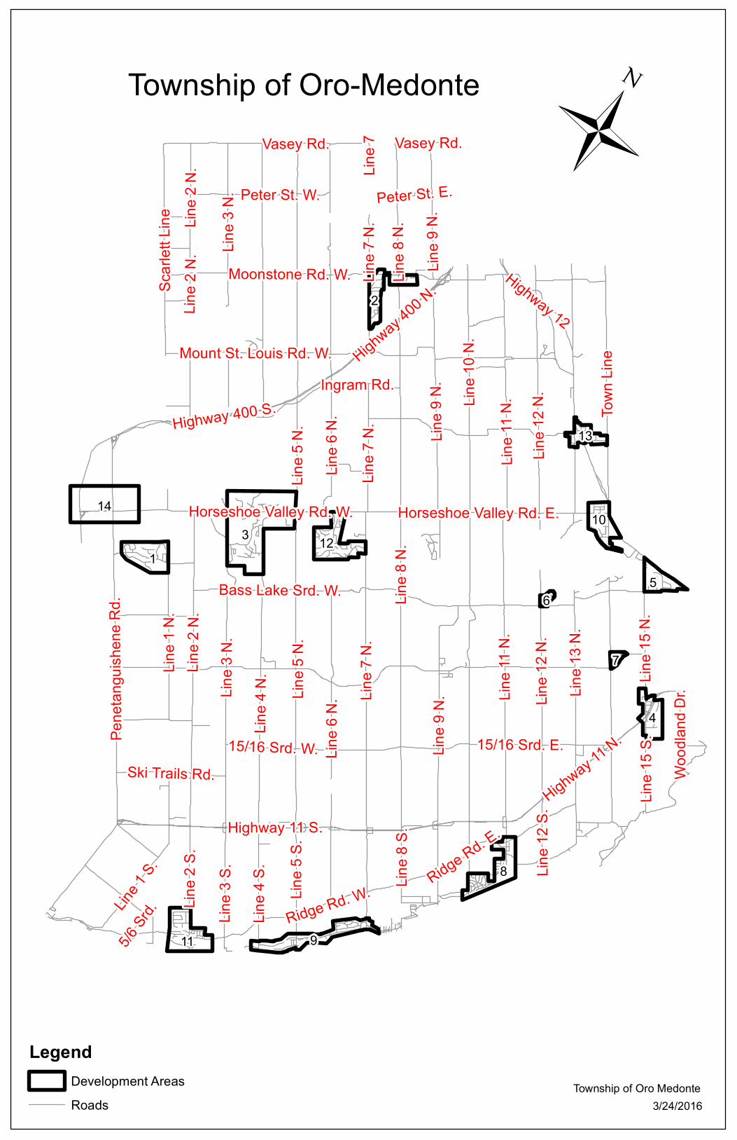
1.3 Township Mapping Index
Township of Oro-Medonte (Overall)
Development Areas
1 – Bidwell
2 – Moonstone
3 – Horseshoe Valley
4 – Forest Home
5 – Bass Lake
6 – Big Cedar Estates
7 – Fergus Hill Estates
8 – Hawkestone
9 – Oro Station - Lakeshore Road
10 – Prices Corner
11 – Shanty Bay
12 – Sugar Bush
13 – Warminster
14 – Craighurst
314
8
1
2
4
11
12
5
10
9
13
7
6Line 8
N.
Line 1
0 N.
Highway 11 S.Highway 11
N.
Line 7
N.
Highway 12
Line 1
1 N.
Highway 400 N.Lin
e 4 N
.
Line 9
N.
Town
Line
Ridge Rd. W.
Pene
tangu
ishen
e Rd.
Line 1
2 N.
Highway 400 S.
Line 6
N.
Ingram Rd.
Vasey Rd.
15/16 Srd. E.
Ridge Rd. E.
Line 3
N.
Line 1
3 N.
Line 1
N.
Scarl
ett Li
ne
Line 1
5 N.
Line 1
S.
Line 2
S.
Line 4
S.
Line 3
S.
Line 5
S.
Line 5
N.
Horseshoe Valley Rd. W.
Peter St. W.
Moonstone Rd. W.
15/16 Srd. W.
5/6 Sr
d.
Horseshoe Valley Rd. E.
Bass Lake Srd. W.
Line 1
5 S.
Wood
land D
r.
Mount St. Louis Rd. W.
Ski Trails Rd.
Line 2
N.
Line 8
S.
Line 1
2 S.
Line 7
Peter St. E.
Line 9
N.
Line 2
N.
Line 7
N.
Line 7
N.
Line 8
N.
Line 1
1 N.
Vasey Rd.
Line 3
N.
Line 5
N.
Line 9
N.
Line 1
2 N.
Line 6
N.
Line 2
N.
ÜTownship of Oro-Medonte
3/24/2016Township of Oro Medonte
LegendDevelopment AreasRoads

Line 1
N.
Bidwell Rd.
Pene
tangu
ishen
e Rd.
30/31 Srd. W.
Maple Ridge Rd.
Northwood Ct.Oak Ridge Rd.
Green Mountain Ct.
Red Pine Ct.
Heml
ock C
res.
30/31 Srd. W.
ÜBidwell RoadDevelopment Area 1
3/24/2016Township of Oro Medonte
Key Map

Line 7
N.
Line 8
N.
Highway 400 S.
Highway 400 N.
Moonstone Rd. E.
Alpine
Dr.
Bachly Ave.Ellen Dr.
Boyd Cres.
Slalom
Dr.
Agnes St.
Valleyview Dr.
Duncan Dr.Jenn
ett D
r.
Brec
hin C
res.
Old C
ounty
Rd.
Glac
ier C
res.
Line 8
N.
ÜMoonstone
3/24/2016Township of Oro Medonte
Development Area 2
Key Map

Line 4
N.
Line 3
N.
Bass Lake Srd. W.
Highland Dr.
Horseshoe Valley Rd. W.
Pine R
idge T
r.
Alpine WayNordic Tr.
Trilliu
m Tr.
Bridle PathValleycrest Dr.
Birch Grove Dr.
Pod'S Ln.
Fairw
ay C
t.
Chestnut Ln.
Landscape Dr.
Pine Point
ÜHorseshoe ValleyDevelopment Area 3
3/24/2016Township of Oro Medonte
Key Map

Line 1
5 N.
Line 1
5 S.
Highway 11 N.
Highw
ay 11
S.
Memorial Ave.
Fores
t Plai
n Rd.
Fores
t View
Rd.
Paterson Rd.
Jamieson Dr.
Jamieson Cres.
Shelswell Cres.
ÜForest Home
Township of Oro Medonte3/24/2016
Development Area 4
Key Map

Line 1
5 N.
Highway 12
Bass Lake Srd. E.
Orsi Dr.
Hawthorn Pl.
Hepin
stall P
l.
Goss Rd.
Sunset Cres.
Atlan
tis D
r.
Heale
y Beac
h Rd.
Barr Ave.
Rutledge Rd.
Ganton Rd.
Devitt St.
ÜBass Lake
3/24/2016
Development Area 5
Township of Oro Medonte
Key Map
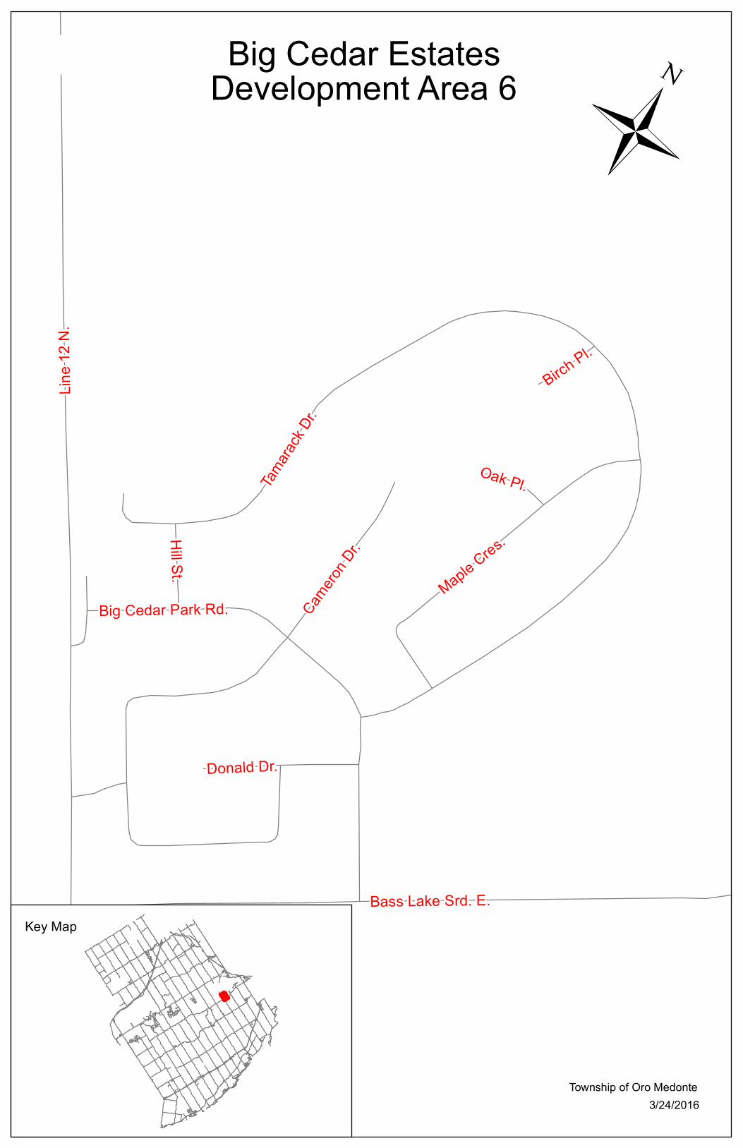
Line 1
2 N.
Bass Lake Srd. E.
Tamara
ck Dr.
Camero
n Dr.
Maple Cres.
Big Cedar Park Rd.
Donald Dr.
Hill St.
Oak Pl.
Birch Pl.
ÜBig Cedar Estates
3/24/2016Township of Oro Medonte
Development Area 6
Key Map

Line 1
4 N.
Old Barr
ie Rd. E
.
Langman Dr.
Muir Dr.
Jane
St.
Bensley Dr.
Irvine
Rd. Fergushill Rd.
Balantrae Dr.Montgreenan Dr.
Orr Dr.
Garnock St.
Claremont Cres.
ÜFergus Hill Estates
3/24/2016Township of Oro Medonte
Development Area 7
Key Map

Line 1
0 S.
Line 1
1 S.
Ridge Rd. E.
Mill S
t.Sokil Blvd.
Campbell Ave.
Stanley Ave.
Kennedy Ave.
Allen
St.
Myrtle Ave.Dorothys Dr. Charl
otte A
ve.
Shewchenko Rd.
Rosemarie Dr.
Cedarbrook Cres.
Franko St.
Pugsley Ln.
Hlynka Pl.
Mariposa Cres.
Karpatian Pl.
Matilda St.
ÜHawkestone
3/24/2016Township of Oro Medonte
Development Area 8
Key Map

Ridge Rd. W.
Line 4
S.
Line 5
S.
Line 7
S.
Lakeshore Rd. W.
Line 6
S.
Shelswell Blvd.
Windfield Dr. W.
Howard Dr.Elvyn Cres.
Ridge Rd. E.
Lakeshore Rd. E.
Brambel Rd.
Windfield Dr. E.
Some
rset B
lvd.
Elm Ct.
Line 6
S.
Ü Development Area 9Lakeshore Road
3/24/2016Township of Oro Medonte
Key Map

Highw
ay 12
Bass
Line
Ward Ave.
Price Dr.
Joy Ave.
Olive
Dr.
Horseshoe Valley Rd. E.
Lakeview Dr.
Orser Dr.
Bards Beach Rd.
Glen
grove
Ave.
Broadview Ave.
Alberta Ave.
Nelson St.
Uno D
r.
Farm
ington
Cres
. ÜPrices Corners
Bass Lake
3/24/2016Township of Oro Medonte
Development Area 10
Key Map

Ridge Rd. W.
Line 3
S.
Line 2
S.
5/6 Srd.Lin
e 1 S.
Bay St.
Rang
e Rd.
William St.
Walnu
t Dr.
Red O
ak C
res.
O'Br
ien St
.
Martine Cres. Raikes St.Graham St.
Pemberton Ln.
Forrester Rd.
ÜShanty Bay
Lake Simcoe
3/24/2016Township of Oro Medonte
Development Area 11
Key Map

Line 7
N.
Horseshoe Valley Rd. W.
Line 6
N.
Diamond
Valley
Dr.
Huron
wood
s Dr.
Oneida Ave.
Ironw
ood T
r.
Sugarbush Rd.Ch
erry T
r.
Hickory Ln.
Iroquois Ridge
Algonquin Tr.
Sene
ca Ln
.
Sapphire WaySuma
c Cres
.Monica Ct.
Emerald Terrace
Topaz Ct.Cayuga Ct.
Maple Ct.
Ash Ct.Lin
e 6 N
.
ÜSugar Bush
3/24/2016Township of Oro Medonte
Development Area 12
Key Map

Town
Line
Highway 12
Line 1
3 N.
Warminster Srd.
Merrington Ave.Pres
ton St
.
Champlain Cres.
Riche
lieu R
d.
Wallis St.
Robbins Dr.
Burne
t St.
Demont Dr.
ÜWarminster
3/24/2016Township of Oro Medonte
Development Area 13
Key Map

Highw
ay 40
0 N.
Pene
tangu
ishen
e Rd.
Horseshoe Valley Rd. W.
Mcnu
tt Rd.
Ingram
Rd.
Procee Cir.
3/24/2016Township of Oro Medonte
Key Map
CraighurstDevelopment Area 14 Ü

15
SECTION 2 – POLICIES and PROCESS
2.1 Pre-Servicing Policy
Subsequent to Draft Plan Approval and prior to execution of a Subdivision Agreement,
the Township may consider agreeing to allow the pre-servicing of a subdivision at the
Developer’s risk when the following conditions have been met:
Written acceptance from the Township for specific works for which pre-servicing
can proceed.
Engineering drawings have been accepted for construction of the works under
consideration.
Written approval of various agencies, e.g., Lake Simcoe Region Conservation
Authority, Nottawasaga Valley Conservation Authority, Ministry of the Environment
and Climate Change, Ministry of Natural Resources, Ministry of Transportation,
Ministry of Tourism, Culture and Sport, where they relate to installation of services
permitted by pre-servicing.
Written confirmation from utility companies including, but not limited to, Hydro One,
Bell Canada, Rogers Cable and Enbridge Gas, that satisfactory agreement has
been reached for provision of respective services.
No permission shall be given to construct external services prior to full registration
unless a Letter of Credit for 110% of the entire cost of the external services
including all restoration has been deposited with the Township. Connections to
existing services shall not be permitted until the plan of subdivision is registered.
All other documents considered necessary to the works including 0.3 m reserves,
easements, etc., must be approved as to form and description.
Cash deposits for engineering and legal fees for the Township, in an amount
determined by the Township, must be paid to the Township prior to the
commencement of any works.
An Insurance Certificate naming the Township as co-insured is to be submitted with
minimum coverage to be $5,000,000.00 or an additional amount as determined by
the Township.

16
A cash or Letter of Credit deposit as security to facilitate siltation and erosion control
and potential emergency maintenance work by the Township is to be submitted in
an amount determined by the Township.
A Cash or Letter of Credit deposit as security to facilitate a Letter of Credit for 50%
of the estimated cost of all internal services has been deposited with the Township.
If the underground pre-servicing has been completed to the satisfaction of the
Township prior to the registration of the plan of subdivision, the Township shall not
require the full value of the Letter of Credit provided an appropriate reduction
request has been submitted and approved by the Township.
The Developer is required to enter into a formal Pre-Servicing Agreement based on
the scope of development.
Applicable fees submitted to the Township for preparation of a Pre-Servicing
Agreement as required by the Township’s Fees and Charges By-law 2015-115 (or
most recent By-law), Schedule E
All required zoning by-laws must be in effect.
2.1.1 Model Homes
Subsequent to Draft Plan Approval and prior to execution of a Subdivision Agreement,
the Township may consider allowing the construction of a model home (which may or
may not be used as a sales office) at the Developer’s risk, when the following conditions
have been met:
A Pre-Servicing Agreement has been executed and all requirements are met.
Applicable fees submitted to the Township for preparation of a Pre-Servicing
Agreement as required by the Township’s Fees and Charges By-law 2015-115 (or
most recent By-law), Schedule E Zoning for the proposed development is in place.
An agreement for the construction of a model home has been executed with the
Township dealing with:
Provision of a builder’s road.
Provision of fire protection.

17
Provision of services (sewer, water, hydro) if available. If not Fire Department
approval shall be required.
The overall grading plan has been approved and there has been preliminary
acceptance of the drainage system for the model home lots.
For a model home building permit application, security is provided to the
Township in the amount of $10,000.00 to ensure that the obligations of the
Developer are carried out as required by the terms of the Agreement or provide
for the demolition and removal of the structure if the subdivision plan does not
proceed to registration within one year.
Confirmation that the model homes shall not be occupied until after the
registration of the Subdivision Agreement and Plan and all requirements within
the Subdivision Agreement are met.
Confirmation that issuance of building permits for model homes is entirely at the
risk of the Developer and without liability or responsibility to the Township. The
Developer shall indemnify the Township from all damages arising in connection
with the issuance of building permits for model homes.
Confirmation that the Developer agrees that the use of model home lots shall
be restricted to the following: parking; a sales office; model homes display.
2.1.2 Sales Office
In the event the Developer intends to utilize a trailer or temporary structure or
combination of both as a sales office subsequent to Draft Plan Approval and prior to
execution of a Subdivision Agreement or registration of a Site Plan Agreement the
Township may consider allowing the construction under the following conditions:
The sales office is to be located on a proposed lot fronting on an existing opened
road allowance.
Zoning for the proposed development is in place.
An agreement for the sales office has been executed with the Township dealing
with:
An acceptable site plan.
Provision of fire protection.

18
Provision of services (sewer, water, hydro) if available. If not Fire Department
approval shall be required.
The overall grading plan has been approved and there has been preliminary
acceptance of the drainage system for the sales office lot.
Security is provided to the Township in the amount of $10,000.00 to ensure the
obligations of the Developer are carried out as required by the terms of the
Agreement or provide for the demolition and removal of the structure if the
subdivision plan does not proceed to registration within one year.
Applicable fees submitted to the Township for preparation of a Pre-Servicing
Agreement as required by the Township’s Fees and Charges By-law 2015-115
(or most recent By-law), Schedule E
Confirmation that issuance of a building permit for the sales office is entirely at
the risk of the Developer and without liability or responsibility to the Township.
The Developer shall indemnify the Township from all damages arising in
connection with the issuance of building permits for the sales office.
Confirmation the Developer agrees the use of the sales office lot shall be
restricted to parking and the sales office.
One sales office shall be allowed for marketing homes within the development.
2.2 Subdivision Agreements
2.2.1 Preparation of Subdivision Agreement
The draft of the Subdivision Agreement shall be prepared by the Township and may be
subject to review by the Township Solicitor. The final Subdivision Agreement shall be
prepared under the direction of the Director of Development Services in consultation with
various Township departments, who shall obtain Council’s approval for the execution of
the Agreement.
The Director of Development Services must be in a position to clear all conditions of
Draft Plan Approval prior to the execution of the Subdivision Agreement.

19
In conjunction with preparation of the Subdivision Agreement the Developer’s
Consulting Engineer shall provide the Township with the appropriate number of copies
(including electronic copies) of the following:
Ministry of Environment and Climate Change Applications for approval for
Township services to be constructed for the proposed subdivision.
The name of the person and title and/or company and Mortgagees with whom
the Subdivision Agreement shall be executed. The Developer’s address and
telephone number shall be provided.
The name, address and telephone number of the Developer’s Solicitor.
The Transfer / Deed of Land (Form 1 Land Registration Reform Act).
The legal description of the subdivision, based on the Reference Plan.
The proposed final plan for registration (M-Plan) complete with the road names, lot
numbers, surveyor’s certificate, Developer’s certificate and all other pertinent
information required by the registry office.
The final draft reference plans for any easements to be granted to the Township.
The engineering drawings, accepted by the Township.
The “M” and “R” Plans reduced to legal size.
A breakdown of the number of units proposed within the subdivision:
Single-family units
Semi-detached units
Townhouse units
Apartment units
one bedroom and bachelor
two or more bedrooms
An O.L.S. certificate in tabular form identifying and certifying all lots and
corresponding frontages, depths and areas are in compliance with the appropriate
Zoning By-Law.
A detailed cost estimate of Township services to be constructed for the subdivision.
The cost estimate shall be signed and sealed by the Developer’s Consulting
Engineer.

20
An Insurance Certificate is to be submitted naming the Township as co-insured
with minimum coverage to be $5,000,000.00 or an additional amount as
determined by the Township.
The estimated cost of Services shall be detailed to show individual items of
construction. This estimate shall be used as a basis for calculation of the security to be
posted for the development.
The total estimated cost of Services shall include the following:
Detailed cost of services, in the format provided by the Township;
The actual estimated cost of streetlighting and associated underground
distribution system;
Any other miscellaneous expenditures required by the Subdivision Agreement as
the Developer’s obligation, such as park equipment, park landscaping,
development of open space, walkways and sidewalks, fencing, etc.;
Allowances for contingencies and engineering in the amount of 15% of the
estimated cost of services;
H.S.T.
The Developer shall provide the Township with written confirmation from the
following utility authorities that satisfactory arrangements have been made for the
installation of services in the proposed subdivision, at no cost to the Township:
Bell Canada
Cable TV Company
Canada Post
Enbridge Gas
Hydro One
Trans Canada Pile Lines (T.C.P.L.)
Any other Authority as required.

21
In addition to the above, Location Approvals shall also be submitted by the appropriate
Utility Authorities. Where requested, easements shall be provided for utilities, at no cost
to the Utility or Township.
Proposed timetable for construction of services.
Proposed landscaping plan and/or park development plan where required.
Proposed phasing plans.
Other information as required for the Subdivision Agreement.
2.2.2 Requirements Prior to Commencement of Construction
Prior to commencement of construction, the Developer’s Consulting Engineer shall
submit the following information to the Township for approval (Allow a minimum of 2
weeks for review).
Three (3) sets of all construction specifications.
The proposed Contractor and Subcontractors.
The Contractor’s list of suppliers.
One (1) copy of the signed contract documents complete with unit prices.
All other information specified in the Subdivision Agreement as a requirement prior
to commencement of construction or other information required by the Township.
Ministry of Natural Resources, NVCA, LSRCA and/or DFO work permits for works
within water bodies.
2.3 Administration Fees, Securities and Development Charges
The administration fees, securities and development charges applicable to subdivision
development are stipulated in the Subdivision Agreement. Reductions in securities
shall be considered in accordance with the provisions of the Subdivision Agreement.
(A sample letter is included on the next page.)

22
Sample Letter - Request for Reduction in Letter of Credit
Date:
Township of Oro-Medonte
148 Line 7 South
Oro, ON L0L 2X0
Attention: Director of Development Services
Re: (Name of Subdivision)
On behalf of the owners of the above development, we are requesting your
consideration and approval of a reduction in the amount of the letter of credit held by the
Township as performance and maintenance security.
We have attached hereto a summary listing the value of the work completed to date,
based upon the Schedule of Construction Costs included in the Subdivision Agreement,
revised as noted to reflect all required alterations to the works. The current value of
securities is calculated as follows:
1) Value of outstanding work $
(inc. contingency, engineering fees and HST)
2) Maintenance Holdback $
(10% of original securities)
Total $
We are also attaching a Statutory Declaration by the owner that all outstanding
accounts relative to work in this subdivision have been paid.
Yours very truly,
(Signature of Engineer)
Name of Engineering Firm

23
2.4 Submission Requirements and Approvals
Introduction
This section outlines the required submissions to be made to the Township.
All submissions are to be coordinated by the Developer’s Consulting Engineer.
The Developer’s Consulting Engineer shall deal directly with other commenting
Authorities, (i.e. County of Simcoe, Ministry of the Environment and Climate Change,
Ministry of Natural Resources, Department of Fisheries and Oceans, Ministry of
Transportation, Lake Simcoe Region Conservation Authority, Nottawasaga Region
Conservation Authority, etc.) for works that fall within their jurisdiction. It is the
Developer’s Consulting Engineer’s responsibility to ensure that all correspondence and
comments are to be provided to the Township of Oro-Medonte at the appropriate
submission time. Second and Final submissions are not to be made until the
Township’s and other authorities’ comments regarding the first and second submission,
respectively, have been received and incorporated.
All work to be done in compliance with Township Standards must be approved.
The Director of Engineering and Environmental Services is to be notified of any such
work that shall be commenced at least forty-eight (48) hours prior to it commencing.
Where the Director of Engineering and Environmental Services requests a site meeting
prior to construction, such meeting shall normally include the Director of Engineering
and Environmental Services, major utility representatives, the Developer, the
Developer’s Consulting Engineer and the General Contractor. The Developer shall
convene such a meeting on the site at the convenience of the Director of Engineering
and Environmental Services, prior to any work commencing and after approval of the
plans.
Prints of drawings for all submissions shall be in accordance with Township Standards
and each print shall be stamped with the submission number (1, 2, or 3) and date of
submission.

24
2.4.1 Engineering Requirements for Draft Plan Approval
A Preliminary Engineering Report must be submitted by the Developer’s Consulting
Engineer. This report must be presented in a readable, comprehensive and
professional manner. The Report must be signed and sealed the Developer’s
Consulting Engineer.
This Preliminary Report shall contain the following and be submitted with the
appropriate number of copies (including electronic copies) of the following:
2.4.1.1 The Draft Plan
The Draft Plan must be in compliance with the Planning Act, as amended, and in a
form acceptable to the Development Services Department.
2.4.1.2 Contour Plan
This plan must be at a scale of no larger than 1:1000 giving contour lines at
sufficient intervals to permit assessment of existing surface drainage patterns.
Contour intervals shall not be greater than 1.5 metres. This plan is to extend to 5
metres past the limits of the drainage area to be served by proposed sanitary and
storm sewer systems, including lands beyond the boundaries of the subdivision. For
large external drainage areas, separate Contour Plans at a larger scale may be
provided. All elevations are to refer to Geodetic Datum.
2.4.1.3 General Plan of Services
The General Plan of Services shall be a plan based on the Draft Plan and must
schematically show the proposed storm and sanitary sewer systems and watermain
and their connection to existing systems. Direction of flow must be indicated on all
sewers. This plan is to be accompanied by preliminary engineering calculations
indicating the quantity of flows at the connection to existing systems and/or at
proposed outfalls. Consideration must be given to the whole catchment area to

25
ultimately be developed. Blocks and easements for storm and sanitary sewers,
stormwater management facilities and watermain systems shall also be shown.
Preliminary road profiles and area grading requirements must also be identified in
the Preliminary Report. Blocks of land for community mail centres must be identified
on the Draft Plan and the General Plan of Services.
Proposed noise attenuation barriers are to be shown (as required).
2.4.1.4 Drainage Plan
When a natural drainage channel passes through and / or is affected by the
construction of the subdivision, drawings must be submitted to indicate the location
and typical cross-sections of the existing channel and of any proposed changes. In
general, creek diversions shall not be permitted unless approved in advance by
the appropriate Conservation Authority. An erosion-sediment control plan shall be
required. A preliminary stormwater management plan and report shall be required
by the Township in accordance with the requirements outlined in this document.
The Developer’s Consulting Engineer must submit an outline of the siltation and
erosion control plan in accordance with the requirements of these Standards.
All drainage designs shall be carried out in general compliance with the MOE
Stormwater Management Planning and Design Manual (March 2003) as amended.
Site specific stormwater management reports shall be consistent with all applicable
background reports prepared by the Township or Conservation Authority (i.e.,
Watershed Planning Studies, Master Drainage Plans, Stormwater Management
Master Plan, etc.), including the Lake Simcoe Protection Plan.
If the overland flow route travels across downstream property not municipally owned,
the Developer must obtain the necessary agreement(s) from downstream owner(s)
accepting the increased quantity of runoff.

26
Any proposed modifications to an existing channel and/or floodplain shall (if
applicable) require MNR, MOECC, LSRCA, NVCA and/or DFO review and approval.
The Developer’s Consulting Engineer must consult with staff from the appropriate
agency(s) and confirm their requirements, prior to proceeding with the preliminary
engineering report.
2.4.1.5 Geotechnical and Soils Report
In new developments, the Developer shall engage a Geotechnical Consultant to
prepare a report on the existing soil conditions which is to include:
sub-surface soil and groundwater conditions and the ability of the soils to
structurally support underground services, roadways and foundations for
residential, commercial, or industrial type structures.
determine the elevation of seasonal high groundwater and comment on minimum
foundation elevations to avoid buildings constructed below groundwater.
The identification, description and limits of the existing soil regimes, including the
extent of topsoil and its suitability for reuse.
The suitability of native materials for trench backfill.
The conditions under which the native material may be used as trench backfill.
The procedures to be used for high moisture contents and water table levels,
which may affect the proposed servicing or structural works of the concerned
area and surrounding lands.
The extent of native material which is unsuitable for trench backfill and the
procedure for dealing with it such that it shall not affect the structural stability of
the proposed Township services.
Areas and procedures to be followed where blasting may be required with due
consideration to surrounding structures and services.
The road material depths for pavement design.

27
Special recommendations for bedding materials.
Potential corrosive or chemical problems that may affect services or structures
(e.g. high sulphates) and the method of resolving such problems.
Recommendations in dealing with filling conditions within the road allowances, on
building lands, in the construction of berms etc.
Identification of problem areas and recommendations for mitigating procedures
regarding the stability of existing slopes and the extent of unstable soils or
conditions.
Special recommendations to be followed in the design and construction of
building foundations including recommended foundation elevations in relation to
the groundwater elevation.
The engineering properties of the native material including frost susceptibility,
natural moisture content, compaction characteristics, relative density and
structural integrity.
Recommendations for achieving proper compaction.
Recommendations for dealing with deep excavation of trenches.
Recommendations for dealing with septic or well systems that may be affected
by the proposed building and servicing works.
Confirmation that sufficient boreholes have been taken to establish definite
requirements and recommendations for the servicing and building works. In
general the geotechnical report must identify minimum bearing capacity of the
native soil (i.e. 75 kPa) preferably on a hole-by-hole basis. Boreholes located in
the area of proposed underground Township services are to be taken to a depth
of at least one (1) meter below the deepest trench.
Requirements and recommendations contained within this report along with
borehole logs and grain size analysis of the native soils are to be incorporated by
the Developer’s Geotechnical Engineering Consultant into their first submission

28
to the Township. Any such requirements and recommendations not incorporated
are to be drawn to the Township’s attention with specific reasons.
2.4.1.6 Hydrogeological Report – Rural Development
The proponents of a draft plan application proposing individual water supply wells
and sewage disposal systems shall provide a detailed Hydrogeological Report
prepared by a qualified Hydrogeologist, relating to the soil types and their ability to
physically accommodate private sewage disposal systems, the availability of
potable groundwater supplies from the proposed water supply sources, the
anticipated quantitative and qualitative impacts within the development and with
neighbouring water sources, and proposed mitigative measures.
Preliminary on-site testing must be reviewed with the Township and must be
sufficient to support the proposed residential density. Test wells shall be drilled and
pump testing performed to carry out the hydrogeological investigation, in
accordance with the latest MOECC guidelines. The proposed monitoring program,
prior to, during and after construction shall be submitted by the hydrogeologist to
the Township for review.
2.4.1.7 Water Mains and Sanitary Sewers
Where water mains and sanitary sewers are proposed, comprehensive servicing
reports shall be prepared and submitted to the Township. Available capacity in
existing water treatment and sewage treatment plants must be taken into
consideration. Where public communal water systems are proposed the
requirements of Section 3.8 shall apply.
2.4.1.8 Traffic Study
A Traffic Study (Traffic Studies) may be required at the discretion of the Township,
County and M.T.O., as applicable roads authorities

29
2.4.1.9 Noise Attenuation
A feasibility noise study or detailed noise study may be needed to support
the development proposal.
All reports must follow the Ministry of Environment - Noise Assessment
Criteria in Land Use Planning Publication LU-131.The Ministry of
Environment requires the use of the Ontario Road Noise Analysis Method for
Environment and Transportation (ORNAMENT) to assess the noise impact
from existing roadways on planned residential land uses, to assess the noise
impact of roadway projects, and to establish the ambient noise sources and
for complaint investigation. A qualified Professional Engineer, with
experience in environmental acoustics, must certify implementation of noise
control measures.
2.4.2 Engineering Submissions
2.4.2.1 First Engineering Submission
Letters of Retention – One (1) original copy of each
A Letter of Retention to the Township from the Developer’s Consulting Engineer for
the design and complete general construction inspection of all municipal services.
A Letter of Retention to the Township from the Developer’s Electrical Engineer for
the design and construction inspection of all streetlight works.
A Letter of Retention from the Developer’s Geotechnical Engineer for the
inspection and certification ensure that the geotechnical operations are in
compliance with the Township’s specifications.
A Letter of Retention to the Township from the Developer’s Landscape Architect
for the design and inspection of all streetscape and stormwater facility plantings
and Parkland Development.

30
Reports and Studies
Three (3) copies of the following reports and calculations and a copy in digital form on CD are required:
Stormwater Management Report and storm sewer calculations on standard
design sheets.
Water supply and distribution report providing calculations to support the design
of the distribution works including main sizes, fire flows and anticipated flows and
pressures for domestic and other users.
Sanitary design calculations on standard design sheets.
Geotechnical Report.
Traffic Studies and Analysis Report (if required).
Noise Attenuation Report (if required).
Arborist Report (if required).
In addition to the above listed reports, the following shall also be provided:
Two (2) copies of the Archaeological Assessment (if required).
Two (2) copies of the Illumination calculations (if required).
A letter from the Developer’s Geotechnical Engineering Consultant, summarizing
the contents of the submission and certifying the design conforms to the
Township of Oro-Medonte Development Engineering Policies, Process and
Standards.
Two (2) copies of all other reports as required by the Draft Plan Conditions /
Approval.
Drawings
Three (3) complete sets of the following drawings and a copy of all drawings and a copy in digital form on CD are required:
Title Page
Approved Draft Plan (Three (3) 11”x17” reductions of the Draft Plan shall
also be submitted.)

31
Proposed Legal Plan for Registration - showing all lot, block and proposed
easement numbering and dimensions
General Servicing Plan(s)
Composite Utility Plan(s)
Overall Site Grading Plan(s)
Preliminary Lot Grading Plan(s)
Stormwater Drainage Design
Stormwater Retention Pond Design
Sanitary Collection Design
Water Distribution Design
Plan and Profile Drawings
Electrical Design and Streetlighting Plan(s)
Erosion Sediment and Silt Control Detail Drawings
Standard and Special Details Drawings
Landscape and Streetscape Plan(s)
Parkland Development Plan(s)
Grading Plan(s) for Park and / or School Blocks
Municipal Structures Submission
When a new roadway structure (i.e. bridges, culverts, water crossings) is proposed,
a specific submission related to the structure is required, which includes the
following information:
Three (3) copies of the General Arrangement drawing(s), prepared in general
accordance with the MTO Structural Manual. The General Arrangement Plan shall
include the roadway structure plan, profile, elevation and cross sections.
Three (3) copies of the Design Report which includes but is not limited to the
description of the works, how the detail was arrived at, different options and cost
analysis/least expensive alternate.

32
Three (3) copies of the Design Criteria Sheet which shall include (but is not limited
to): the type/class of roadway, volume of traffic, geometric information and cost
estimate.
Three (3) copies of the Geotechnical Report.
Three (3) copies of the Hydrology Report.
An original letter from the Professional Engineer responsible for the design and which certifies that:
The bridge type, length and width are appropriate;
HBDC requirements are met;
Ministry standards have been followed;
The most economical life cycle cost solution has been selected for the site;
Canadian Highway Bridge Design Code has been adhered to.
The structural design drawings and details included as part of the Subdivision
Agreement shall be stamped and signed by the Engineer who designed the
roadway structure and by the professional engineer who check the structural
design drawings.
Parks and Landscaping Submission
A covering letter from the Developer’s Consulting Engineer and/or Landscape
Architect stating the landscape work is in conformity with the proposed grading and
Township services for the development, plus an outline of the items contained
within the submission.
Three (3) copies of the following drawings (where applicable):
Existing Natural Features Assessment
Tree Survey/Vegetation Analysis and Tree Preservation Plan
Streetscape and Buffer Planting Plans
Detailed Park Development Plans
Stormwater Management Pond Planting Plan
NOTE: The Developer may request jointly obtaining a Landscape Architect with the
Township (costs to be borne by the Developer).

33
2.4.2.2 Second Engineering Submission
The following plans and documents, as a minimum, are required for the second
submission:
Detailed chart or report with all of the First Submission “red lined” comments and
how they have been met.
Copies of all other applicable approval agencies comments.
Three (3) complete sets of all revised drawings, proposed M- and R- Plans.
One (1) original plus one copy of Ministry of Environment application forms,
signed by the Developer and the Developer’s Consulting Engineer.
Three copies of the Subdivision Agreement Schedules Pertaining to Engineering
Submission and all applicable cost estimates.
Three (3) copies of Utility Coordination Plan.
Three (3) copies of streetlight design plans.
In addition to storm sewers, sanitary sewers and water mains, MOECC approval
is required for proposed engineered channels, storm water detention ponds and
storm water management features. The MOECC Application shall be signed only
when the engineering design has been approved. The Developer’s Consulting
Engineer is responsible for forwarding the complete application to the MOECC.
Parks and Landscaping Submission - A covering letter from the Developer’s
Consulting Landscape Architect outlining the submission contents. Three (3) sets
of revised landscape drawings as per Township comments. Three (3) complete
sets of landscaping cost breakdowns.
NOTE: Subsequent Submissions shall be made, as required, until the drawings and designs are acceptable to the Township.

34
2.4.2.3 Final Engineering Submission
The following plans and documents shall be compiled and submitted in their entirety by
the Developer’s Consulting Engineer in one complete package. Incomplete
submissions, delivered to the Township, shall be returned immediately.
Two (2) copies of the Proposed M-Plan and R-Plan.
One (1) digital copy of the Proposed M-Plan and R-Plan.
Two (2) complete sets of all drawings listed in the Subdivision Agreement,
stamped and signed by the Developer’s Consulting Engineer and/or Landscape
Architect (where applicable).
One (1) digital copy of the complete set of engineering drawings in accordance
with the Township CAD requirements.
Two (2) copies of the final storm drainage plan and the storm sewer design
sheets labelled final design.
One (1) digital copy of the final storm drainage plan and the storm sewer design
sheets labelled final design.
Two (2) copies of all required approvals i.e. MOECC, MTO, NVCA, LSRCA, etc.
A Detailed Cost Estimate of all proposed works.
Two (2) copies of the Developer’s Insurance Certificate naming the Township
as co-insured, as per the Subdivision Agreement.
The Developer shall submit evidence of written agreements with Hydro One,
Bell Telephone Company, Enbridge Gas, and Cable TV Provider for the
installation of these utilities in a common trench in the prescribed locations on
road allowances within the plan of subdivision.
The Developer shall submit evidence in writing that agreements are in place
with Hydro One or any other approved Contractor for the installation of
streetlighting.
The Developer shall submit evidence in writing that satisfactory arrangements
are in place with Canada Post for the location of mailboxes.
A summary of lot area and frontage for each Lot / Block to confirm compliance
with the Township Zoning By-law, prepared by an O.L.S.

35
NOTE 1: The drawing originals shall be signed and stamped “Approved For
Construction” and shall be returned to the Developer’s Consulting Engineer. Two
copies of the complete set shall be returned to the Township. Only drawings accepted
for construction shall be utilized during construction of the works. Changes in drawing
originals by the Developer’s Consulting Engineer are subject to approval by the
Township.
NOTE 2: Submissions are to include the items listed above and are to be submitted in
their entirety by ONE (1) agent of the Developer in ONE (1) complete package.
Incomplete submissions, delivered to the Township, shall be returned as incomplete.
NOTE 3: Upon completion of the construction of the services, the Developer’s Consulting
Engineer shall obtain the ‘as constructed’ field information and revise the original drawings
accordingly. Changes in drawing originals by the Developer’s Consulting Engineer are
subject to approval by the Director of Engineering and Environmental Services.
NOTE 4: No Pre-servicing is permitted including topsoil stripping, blasting, tree removal
or underground servicing works until all drawings and agreements have been approved
and signed unless a Pre-Servicing Agreement has been entered into.
2.5 Conditions of Construction
2.5.1 Blasting or Tunnelling
No blasting or tunnelling shall take place without written approval of the Director of
Engineering and Environmental Services.
2.5.2 Winterizing of Subdivisions
In order to minimise repairs to new subdivision roads and snow plowing equipment, the
Township requires the following works to be carried out prior to November 15th of each
year:
Manhole tops, catchbasin frames and valves on roads with base asphalt shall be
set at the level of the base course asphalt.
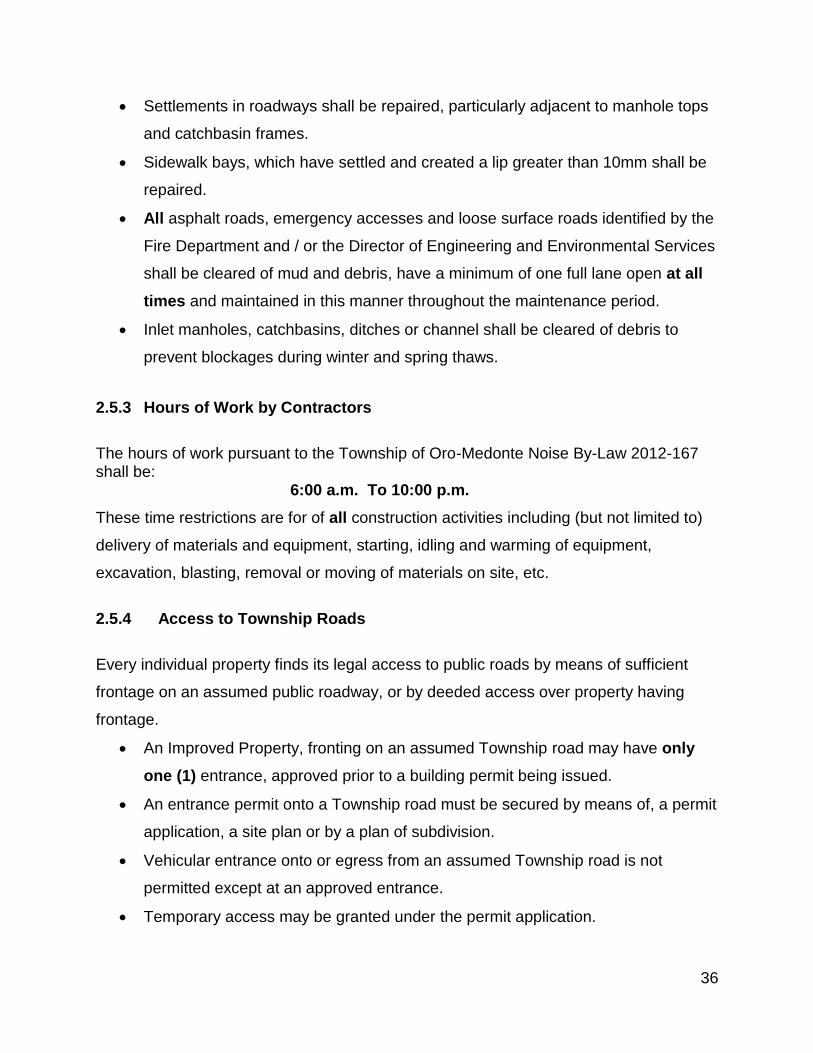
36
Settlements in roadways shall be repaired, particularly adjacent to manhole tops
and catchbasin frames.
Sidewalk bays, which have settled and created a lip greater than 10mm shall be
repaired.
All asphalt roads, emergency accesses and loose surface roads identified by the
Fire Department and / or the Director of Engineering and Environmental Services
shall be cleared of mud and debris, have a minimum of one full lane open at all
times and maintained in this manner throughout the maintenance period.
Inlet manholes, catchbasins, ditches or channel shall be cleared of debris to
prevent blockages during winter and spring thaws.
2.5.3 Hours of Work by Contractors
The hours of work pursuant to the Township of Oro-Medonte Noise By-Law 2012-167 shall be: 6:00 a.m. To 10:00 p.m.
These time restrictions are for of all construction activities including (but not limited to)
delivery of materials and equipment, starting, idling and warming of equipment,
excavation, blasting, removal or moving of materials on site, etc.
2.5.4 Access to Township Roads
Every individual property finds its legal access to public roads by means of sufficient
frontage on an assumed public roadway, or by deeded access over property having
frontage.
An Improved Property, fronting on an assumed Township road may have only
one (1) entrance, approved prior to a building permit being issued.
An entrance permit onto a Township road must be secured by means of, a permit
application, a site plan or by a plan of subdivision.
Vehicular entrance onto or egress from an assumed Township road is not
permitted except at an approved entrance.
Temporary access may be granted under the permit application.

37
All entrances onto a Township road must be installed and maintained by and at
the cost of the property Developer.
The Developer must maintain all entranceway improvements on Township
property in a safe condition. The Township may, with appropriate notice, make
improvements to, or remove, unsafe entrance features at the cost of the
Developer.
2.5.5 Commencement of Construction
Construction of services shall not commence until the Developer has entered into the
necessary agreements with the Township of Oro-Medonte. The Developer must also
have obtained the required approvals from the County of Simcoe, the Ministry of
Transportation Ontario, the Ministry of Environment and Climate Change, or other
agency or authority that may be affected by the plan of subdivision.
2.5.6 Commencement Notice
The Director of Engineering and Environmental Services must be given forty-eight (48)
hours written notice prior to the commencement of construction. Should there be a
cessation of construction of more than a week; the Developer must again supply forty-
eight (48) hours written notice before recommencing the work. Failure to comply with
any portion of the requirement shall lead the Township to increase maintenance periods
in addition to field investigation. The Township must be satisfied that proper
arrangements have been made to assure that all nuisance dust, mud and debris shall
be properly cleaned on a regular basis.
2.5.7 Directional / Informational Signage
The Developer is responsible to erect and maintain the directional / informational
signage to all works commencing and until final acceptance by the Director of
Engineering and Environmental Services or otherwise directed by the Township.

38
An information sign shall be placed at every access point to the subdivision detailing:
the developer, the general contractor and the Developer’s Consulting Engineer. Phone
numbers for each of these companies shall be posted on this sign.
2.5.8 Mud, Dust, Stock Pile & Debris Control
The Developer is required to keep subdivision lands, internal roadways and adjacent
roadways free from nuisance mud and dust at all times.
Roads are to be scraped daily or when mud accumulates, which is ever greater. The
road is to be flushed and / or swept a minimum of once per week or more if required to
assure dust and mud does not become a nuisance or unless otherwise directed by the
Township.
Scattered debris is to be cleaned daily.
Roadways are not to be used for stockpiling materials once the road is open to public
use. If a road is to be blocked for more than two (2) minutes in duration with
construction equipment then an alternative signed detour route must be established as
per O.T.M. – Book 7 requirements.
2.5.9 Construction on Existing Roads
Whenever it is necessary to cut through an existing Township or County road, the
contractor shall be responsible for proper compaction of the backfill material and
replacing the original surface.
Road Occupancy and Road Closure permits must be obtained prior to undertaking
any work on an existing road allowance.
It is the developer’s responsibility to provide the Director of Engineering and
Environmental Services a minimum of forty-eight (48) hours notice prior to commencing
work so that Fire and Emergency Services and School Boards (as required) can be

39
given advance notification. The road must be maintained to a minimum of one lane for
emergency access.
In the event of an unexpected closure, notice must be given to the Township
immediately. All signage and detours must conform to the latest version of the Uniform
Traffic Control Manual.
After roads within a plan of subdivision have been paved with top course asphalt, no
cutting of the asphalt shall be allowed to install services for a period of three (3) years.
Any Contractor installing a service shall require a Road Occupancy Permit from the
Township, even though the roadway remains the Developer’s responsibility for
maintenance.
Unshrinkable fill may need to be utilised as the backfill material from top of cover material to
the frost line, in trench installations within Township road allowances, depending on native
soil conditions. On top of the unshrinkable fill, the trench shall be restored with Granular ‘B’
to the bottom of the Granular A (a minimum of 150mm of Granular A is required) in
accordance with existing road structure composition. Unshrinkable fill shall be per O.P.S.S.
1359.
Where overlaying or constructing new road works, a diagonal joint must be utilised
across the travelled portion of the roadway.
Where proposed road granular material differs from existing road granular material, a
frost taper must be utilised to minimise the effects of the different granular
characteristics.
NOTE: Subdrains shall remain intact and at grade during these restorations.

40
2.5.10 Existing Infrastructure
In general, the Developer may be required to design and construct upgrades to existing
infrastructure or new infrastructure outside the limits of the proposed development, to
support the development, including but not limited to sewer works, water works,
drainage and stormwater management, parkland, roads and sidewalks.
During construction the Developer shall be responsible to protect all adjacent
infrastructure and make repairs to any damage as a result of construction of the
development.
2.5.11 Site Restoration
In all cases the subdivision lands shall be restored and maintained to a condition such
that they are kept free of nuisance debris, mud and dust at all times.
Where earth excavation, brush, muck, stumps, etc. are to be removed from site, they
shall be disposed of in accordance with the latest MOECC approved regulations (at an
approved dump site or landfill location).
In all cases, the ditches, side-slopes and banks shall be restored to a condition
satisfactory to the Township. In both urban and suburban areas this shall include
topsoil, sod or seed with proper after-care of all land on the R.O.W. disturbed during the
construction of the road.
Unless otherwise approved, no earth ditch or embankment shall have a slope greater
than 3:1 run/rise. Where required in the opinion of the Township, a significant structure
or special slope stabilizing procedures may be required.
All rock faces left exposed in cut shall be cleared of loose rock debris. The earth shall
be cut back from the top of the rock by at least 0.5m.

41
2.5.12 Timing of Paving
Paving between October 31st and May 15th shall not be accepted without prior
approval by the Director of Engineering and Environmental Services and satisfactory
documentation provided by the geotechnical inspector as to temperature and weather
conditions. Any paving done between these months without prior approval must be
removed and replaced at the Developer’s expense.
2.5.13 Landscaping Implementation Procedures
2.5.13.1 Streetscape Works
The Developer is required to hire a contractor to install the landscape elements called
for in the approved landscape plans. The Developer’s Landscape Architect shall
inspect the work, report on progress to the Township and provide the Township with as-
built drawings. An important part of the Landscape Architect’s duties shall be to
maintain a Summary Chart documenting the history of each new tree planted in the
parcel of land being developed. At the appropriate times, the Township shall conduct its
own inspections. All streetscape works are to be guaranteed and maintained for 12
months after Final Acceptance and Assumption of the Subdivision.
2.5.13.2 Naturalization Works
As with streetscape works, the process begins with the developer hiring a contractor to
install the landscape elements called for in the approved landscape plans. The
Developer’s Landscape Architect shall supervise the work and report on progress to the
Township. At the appropriate times, the Township shall conduct its own inspections.
All naturalization works are to be guaranteed and maintained for 12 months after Final
Acceptance and Assumption of the Subdivision.

42
2.5.13.3 Maintenance Agreement of Naturalization Areas
Carrying out maintenance programs after planting the naturalization areas significantly
reduces the mortality rate of the trees, shrubs, grasses, etc. and helps to establish
healthy vegetative cover.
At the time of planting, the planting details and specifications shall be followed faithfully.
This means, among other things, the proper transportation and handling of plant
material, the use of fertile planting soil, the proper staking of trees and the proper
installation of rodent protection.
Maintenance shall include:
apply appropriate fertilizer to promote growth
prune dead or diseased tissue
remove dead plant material as necessary
replace dead coniferous or deciduous naturalization species to maintain a
minimum live-stocking standard of 90%
suppress weed growth around new trees and shrubs by adding mulch and/or
removing weeds by hand. Weeds shall not be cut down with a power trimmer.
An assessment of plant material is to be carried out annually by the Landscape
Architect between mid-July and early September and reported to the developer,
the contractor and the Township in the form of a Naturalization Assessment
Report. Plant vigour can be determined by a visual inspection of the current
year’s foliage.
The initial inspection and assessment shall be conducted in the summer
following the planting. It shall take account of the survival and condition of the
plants. It shall also include a summary of the maintenance operations
performed. Finally, the assessment shall propose all additional maintenance
measures necessary, and recommend where, the following spring, plants need to
be replaced or new plants added.

43
The second assessment shall be conducted the following year, and shall provide
similar information to the first.
The third and final assessment shall take place just prior to assumption. The
final report shall provide a complete summary of the initial plantings, as well as a
record of the replacements and maintenance services carried out during the
guarantee period. The report shall also make note of all additional work that
should be performed prior to the Township conducting a final inspection.
2.6 Construction Inspection and Reporting
2.6.1 Inspections
In addition to fulfilling an inspection role for construction, the Developer’s Consulting
Engineer shall serve as liaison between the Developer and the Contractor, as well as
between the Developer and the municipality. They are to ensure the approved design
intent is implemented, to expedite design decisions on site, and to deal with homeowner
enquiries and concerns.
The Developer’s Consulting Engineer must have their own site Inspector on site during
all grading, construction and servicing works. The Inspector shall, at a minimum, have
obtained a C.Tech designation with OACETT or a pre-approved equivalent approved by
the Director of Engineering and Environmental Services. The Developer’s Consulting
Engineer must submit a résumé of the site Inspector(s) for approval from the Township.
If at any time, in the opinion of the Township, the site Inspector(s) is under qualified, the
Engineer shall replace the site Inspector(s) with someone to the satisfaction of the
Township.
It is the Developer’s Consulting Engineer that is responsible to determine what works
are complete and in compliance and which require repair to meet compliance with the
Township Standards. The Director of Engineering and Environmental Services or their
representative shall meet on site with the Developer’s Consulting Engineer and review
the works to determine what is compliant or non-compliant; the Director of Engineering
and Environmental Services or their representative shall only give approval to proceed

44
to the next stage of works once the infrastructure is compliant. Any work that proceeds
prior to approval from the Township shall not be accepted and may be required to be
removed and / or replaced and / or additional warrantee periods may be added beyond
those specified in the Subdivision Agreement.
At the pre-construction meeting, the Developer’s Consulting Engineer and Geotechnical
Engineer shall be required to provide the Township with a schedule of the works,
together with the names & emergency phone numbers of all inspectors to be on site
during the construction of the various phases of the works.
The Township shall have the right to inspect the installation of works and services to
ensure they are being constructed in accordance with Township Standards. Where the
Director of Engineering and Environmental Services or their designate have reason to
believe the work is not being done to the required standard the work shall be stopped
until further notification to proceed from the Director of Engineering and Environmental
Services. The Township may charge a fee for such inspection services.
2.6.2 Inspection Reports
Weekly inspection reports from the Developer’s Consulting Engineer shall be submitted
to the Director of Engineering and Environmental Services at the end of each month for
review. If the reports are not submitted within 10 days of the end of the month, the
Township may place a Stop Work Order on the project until the Township is satisfied
that works are in accordance with Township Standards and those of other authorities.
The diary must at a minimum contain the following information:
Weather Conditions.
General Progress of work; where the Contractor is working and what work is
being done.
Equipment being moved or arriving on the job site and its purpose.
Visits to the site by Township or County Officials and all specific instructions they
may have given.
Instructions given to the contractor.

45
Contractor’s claims or complaints.
Compaction efforts for trench backfill, granular road bedding and asphalt.
Trench conditions.
All discussions or dealings with property owners.
Work performed on the site involving the installation of public utilities.
The actual hours worked
The actual area of work
The time of arrival and departure of the Developer’s Consulting Engineer or their
Inspector.
All pertinent information relating to Quality Assurance of the works.
All erosion and sediment control devices shall be inspected once per week and after each rainfall of 1 cm or greater to ensure that they are in proper working condition.
2.6.3 Geotechnical Inspections and Reports
In new developments, the Developer shall engage a licensed Geotechnical Engineer to
prepare an inspection report on the identification, description and placement of all
engineered materials used throughout the development.
Those materials are (but not limited to):
native materials for trench backfill
trench bedding and backfill materials used on site from supply sources
road construction materials (granular and asphaltic)
concrete used for curbing, sidewalks and structural construction
asphalt and granular materials used for walkways / trailways
During Construction:
The Developer shall retain the Geotechnical Engineer who prepared the
inspection to inspect the installation of bedding and the back filling of all trenches
within road allowances and easements. The trench backfill certification is
required to indicate that sufficient tests have been carried out to obtain an

46
Inspector’s report as to the compaction of the backfill and they find the backfill to
be in compliance with Township specifications and requirements.
The final subgrade certification is to confirm that the final subgrade conditions are
equal to or better than those anticipated in the preparation of the pavement
design. The above certification(s) shall display the Professional Engineer’s
Stamp of the Developer’s Geotechnical Consultant. The certification is to include
the following wording: “This certification has been made to the best of the
Developer’s Geotechnical Consultant’s knowledge and information. This
certification however does not relieve the Contractor, the Developer or any other
parties of their respective responsibilities pertaining to maintenance or
otherwise.”
The findings of the compaction reports and the aforementioned certification, in a
form acceptable to the Township, are to be forwarded to and acknowledged by
the Township prior to placement of the granular road material. The Developer’s
Geotechnical Consultant shall also confirm that the final subgrade conditions are
at least equal to those anticipated in their preparation of the pavement design. If
these conditions are less than what was anticipated, the Developer and the
Township are to be immediately advised with a new pavement design
recommendation.
Where grading operations require the placement of “engineered fill” the
Developer’s Geotechnical Engineer must certify that the fill located at 1.0m below
finished grade and deeper has been sufficiently compacted to assure a minimum
bearing capacity of 75 KPa and a 98% Standard Proctor Density as per O.P.S.S.
514.07.08 regarding back filling and compaction within road allowances and lots
where fill exceeds 1.0m in thickness is strictly adhered to.
Identify problem areas and recommend mitigating procedures regarding the
stability of existing slopes and the extent of unstable soils or conditions.

47
2.6.4 Standards and Maintenance
All work shall be to the satisfaction of the Director of Engineering and Environmental
Services, or their representatives. All work shall be designed and constructed in
accordance with the most recent requirements, Township Standards, specifications and
by-laws of the Township of Oro-Medonte. All Works constructed shall be guaranteed for
such period of maintenance as required hereinafter.
2.7 Approvals - Substantial Completion and Maintenance and / or Final Acceptance and Assumption
The municipal services constructed and installed by the Developer are divided into two
categories: Underground Services and Above Ground Services. The processes for the
Certification, Inspection, Acceptance, Maintenance and Assumption is the same for both
service types. Each service type shall be undertaken independently of the other and
each shall require Certification, notification of Inspection, and requests for Acceptance
and Maintenance or Assumption as outlined below.
2.7.1 Underground Services shall mean storm drainage works (including culverts,
storm sewers and detention pond), waterworks, sanitary works, underground electrical
distribution system and streetlighting serving the development (as applicable).
2.7.2 Aboveground Services shall mean all Municipal services to be constructed by
the Developer pursuant to the terms of the Subdivision Agreement, excluding
Underground Services as previously defined.
2.7.3 Certification
Upon completion of the construction of services, the Developer’s Consulting Engineer
shall provide written certification to the Township that all Municipal Services have been
constructed in accordance with the approved plans and specifications and in
accordance with good engineering practices. The wording is to be followed by the
Professional Engineers stamp and signature.

48
2.7.4 Inspection(s) for Substantial Completion and Maintenance and / or
Final Acceptance and Assumption
Upon substantial completion of works for which a (the) Certificate is being requested,
the Developer shall request the Township to carry out an Inspection for Substantial
Completion and Maintenance of the works in conjunction with Developer’s Consulting
Engineer. All deficiencies found during this inspection shall be immediately corrected by
the Developer. This inspection is for the benefit of the Township and shall not relieve
the Developer of their obligations under the Condominium Act and Site Plan Agreement.
On receipt of the Developer’s request for an Inspection for Final Acceptance and
Assumption of the municipal services, the Director of Engineering and Environmental
Services shall again inspect the work and if satisfied, shall recommend that the
Certificate of Final Acceptance and Assumption Municipal Services be issued.
NOTE: The Certificate of Final Acceptance and Assumption of the Municipal
Services can be applied for by the Developer after a minimum of two (2) years
from the receipt of the Certificate of Substantial Completion and Acceptance.
2.7.5 Certificate of Substantial Completion and Maintenance
Certificate of Substantial Completion and Maintenance shall mean a Certificate
issued by the Director of Engineering and Environmental Services confirming that the
Municipal Services installed by the Developer under the provisions of the Subdivision
Agreement have been substantially completed in accordance with the approved plans
and specifications and in accordance with good engineering practices.
Upon the receipt of certification by the Developer’s Consulting Engineer that all
Municipal Services have been constructed in accordance with approved plans and
specifications and in accordance with good engineering practices and the issue of the
Certificate of Substantial Completion and Maintenance, the minimum two (2) year
maintenance period for constructed Services shall commence.

49
NOTE 1: During the maintenance period, the Developer shall be responsible for all of
the normal operation, maintenance and repairs for the services noted in the Certificate.
If, during the two (2) year maintenance period, the Developer fails to carry out the repair
works as required by the Township, then the Township may carry out the works and
shall be reimbursed the cost of the works from the Developer’s securities.
NOTE 2: During the maintenance period, should substantial repairs or replacement of
municipal services be required, the maintenance period may be extended to
accommodate the need to assess the repairs undertaken.
NOTE 3: The issuance of a Certificate of Substantial Completion and Maintenance
for Above Ground Services shall constitute an assumption of the Aboveground
Services by the Township for winter maintenance only.
NOTE 4: Building Permits shall not be issued until the Certificate of Substantial
Completion and Maintenance for Municipal Underground Services has been
issued.
2.7.6 Maintenance Period
Maintenance Period shall mean the repair and maintenance of all the subdivision
services for which the Certificate of Substantial Completion and Maintenance has been
issued and for a minimum period of two (2) years from the date the Director of
Engineering and Environmental Services issues the Certificate of Substantial
Completion and Maintenance.
The Developer shall be required to maintain this infrastructure in good condition, to
Township Standards, to Manufacturers Specifications and to safe conditions until such
time the Township assumes the subdivision.

50
2.7.7 Certificate of Final Acceptance and Assumption
Certificate of Final Acceptance and Assumption shall mean a Certificate issued by
the Township, as approved by Township Council, upon the receipt of certification by the
Developer’s Consulting Engineer that all works have been constructed in accordance
with the approved plans and specifications and in accordance with good engineering
practices and confirmation by the Director of Engineering and Environmental Services
that the services have been satisfactorily completed and maintained by the Developer
during the two (2) year maintenance period, and issuance of the said Certificate shall
constitute Final Acceptance and Assumption of the services by the Township.
NOTE 1: Security for all Landscaping Works shall be held by the Township for twelve
(12) additional months following the issuance of the Certificate of Final Acceptance and
Assumption.
NOTE 2: Notwithstanding anything hereinafter set out, the Township shall not be
obligated to assume the responsibility for and take over any or all subdivision services
until seventy per cent (70%) of the lots in the subdivision or phase of the subdivision
have completed dwellings erected therein, Occupancy Permits have been issued and
final lot grading approval has been certified. The Developer shall be responsible for the
normal operation, maintenance and all repairs of the services in this case until the
Township has assumed the responsibility of the services.

51
SECTION 3 – DESIGN STANDARDS
3.1 Drawing Index
NOTE: Drawings pertaining to each of the following sections are found in
back of each respective section.
Section 3.2 Engineering Design and Drawing Requirements
3.2-01 Standard Title Page
3.2-02 Standard Plan Sheet
3.2-03 Standard Line Type, Layers and Symbols
Section 3.3 General Servicing Plans
3.3-01 Service Location – Single Family Residential
3.3-02 Service Location – Semi Detached Residential
3.3-03 Service Location – Freehold Townhouse Units
3.3-04 Service Location – Commercial, Industrial and Multi- Residential
3.3-05 Notes - Construction
Section 3.4 Overall Site Grading Design and Construction
Refer to 3.2-02 Standard Plan Sheet
Section 3.5 Road Classification and Design
3.5-01 Urban Residential
3.5-02 Local Residential
3.5-03 Cul-de-Sac Urban Residential
3.5-04 Cul-de-Sac Local Residential
3.5-05 Temporary Turn Around - Urban Residential
3.5-06 Temporary Turn Around - Local Residential
3.5-07 90O Bulb Detail
3.5-08 Local Collector and Industrial
3.5-09 Cul-de-Sac Industrial

52
3.5-10 Major Collector and Industrial
3.5-11 150mm Subdrain Detail
3.5-12 Typical Intersection Requirements
3.5-13 Notes - Roads
Section 3.6 Erosion and Sediment Control
3.6-01 Light Duty Silt Fence Barrier
3.6-02 Heavy Duty Silt Fence Barrier
3.6-03 Sediment Control Measures – Catch Basins
3.6-04 Construction Entrance Mat
Section 3.7 Stormwater Management
3.7-01 Supports for House Connections and Catch Basin Leads
3.7-02 Notes – Storm Sewers
Section 3.8 Water Supply Distribution
3.8-01 Support for Watermain and Sewers Crossing New Trenches
3.8-02 Method of Insulating Watermain
3.8-03 Temporary Connection for Watermain
3.8-04 Tracer Wire Arrangement at Valve Box for P.V.C. Watermain
3.8-05 Corrosion Protection for Tracer Wires on P.V.C. Watermain
3.8-06 Hydrant Barrier
3.8-07 Access Culvert for Fire Hydrants and Hydro Transformers
3.8-08 Air Release Valve in Chamber
3.8-09 Polyethylene Water Service Connection Detail
3.8-10 Water Meter Installation Package
3.8-11 Clayton Mark Heavy Duty Yard Hydrant – Dwg. 1
3.8-12 Clayton Mark Heavy Duty Yard Hydrant – Dwg. 2
3.8-13 Notes - Watermain

53
Section 3.9 Sanitary Collection Sewers
3.9-01 Sanitary Sewer Cleanout
3.9-02 Notes – Sanitary Sewer
Section 3.10 Plan and Profile Drawings
3.10-01 Standard Plan and Profile Sheet
Section 3.11 Utility Coordination, Composite Utility Plan and Electrical Services Design
3.11-01 Joint Utility Trench and Road Crossing Sections
Section 3.12 Streetlight Drawings
3.12-01 Street Light Pole and Horizontal Type Luminaire
3.12-02 Street Light Pedestal
Section 3.13 Signs, Traffic Signals and Pavement Marking
3.13-01 Subdivision Information Sign
3.13-02 Municipal Address Number Sign Location
3.13-03 Standard Street Name and Regulatory Signs
3.13-04 Dead End Barricade
Section 3.14 Sidewalks, Walkways, Trailways and Fences
3.14-01 Concrete Sidewalk
3.14-02 Pedestrian Walkway – Asphalt or Limestone
3.14-03 Pedestrian Walkway – Granular
3.14-04 Chain Link Security Fence
3.14-05 Wood Privacy Fence
3.14-06 Vehicle Access / Pedestrian Walkway Gate
Section 3.16 Landscaping
3.16-01 Deciduous Tree Planting
3.16-02 Coniferous Tree Planting
3.16-03 Shrub Planting

54
Section 3.17 Parkland Development
3.17-01 Standard Park Sign
3.17-01A Standard Park Sign - Colours and Graphics
3.17-02 Park Safety and Regulation Sign
3.17-03 Removable Bollard
3.17-04 Timber Bollard
Section 3.18 Standard Detail Drawings
3.18-01 Standard Detail Sheet
3.18-02 General Notes Sheet
Section 3.20 Residential Lot Grading
3.20-01 Typical Legend for Lot Grading
3.20-02 Rear to Front Draining Lot
3.20-03 Split Lot – Rear Draining
3.20-04 Rear Lot Draining – Walkout or Back Split House
3.20-05 Front Lot Draining – Front Split House
3.20-06 Typical Legend for Lot Grading
Refer to 3.3-01 Service Location – Single Family Residential
Refer to 3.3-02 Service Location – Semi Detached Residential
Refer to 3.3-03 Service Location – Freehold Townhouse Units
Section 3.21 Industrial / Commercial / Institutional Site Plan Design
3.21-01 Driveway Approach Paving – Commercial, Industrial and Apartments (With and Without Sidewalks)
3.21-02 Driveway Approach Paving – Commercial, Industrial and Apartments (Depressed
Curb & Corner Lots) Refer to 3.3-04 Service Location – Commercial, Industrial
and Multi- Residential
Refer to 3.5-08 Local Collector and Industrial
Refer to 3.5-09 Cul-de-Sac Industrial
Refer to 3.5-10 Major Collector and Industrial

55
3.2 Engineering Design and Drawing Requirements
Introduction
The purpose of this section is to outline the minimum design requirements for the
construction of municipal services in the Township. These requirements are intended to
provide guidance to the designer and do not relieve the Developer and their Consulting
Engineer of the responsibility for submitting a completed product demonstrating
competent engineering design in full compliance with all applicable legislation.
Any deviation from the minimum Township Standards shall be specifically referred to by
the applicant and/or their agent with a copy of written approval of the Township
attached.
3.2.1 Specifications for Engineering Drawings
Size: Drawings to be Metric Standard A1 (594 mm x 841 mm) or Imp. Equivalent
Format: Same as Township standard sheets unless otherwise approved.
Materials for Preliminary Submissions:
Bond for Preliminary Submission
Black Ink (permanent)
Digital copies on CD
Materials for Final Submission and As Constructed Drawings:
Bond for Final Submission
Bond for As-Constructed
Black Ink (permanent)
Digital copies on CD

56
3.2.2 General Drawing Requirements
All engineering drawings shall be prepared in metric and in a neat and legible fashion.
The design information presented on these drawings shall be completed in ink.
The standard Township of Oro-Medonte title block as shown in the detail drawings shall
be used on all engineering drawings. A title sheet is required for the engineering
drawings.
Storm and Sanitary Drainage Area Plans may be prepared on a paper size other than
Metric Standard A1 in order for the entire drainage system to be presented on one
sheet.
The lot numbering and block identification on all engineering drawings shall be the
same as shown on the Registered Plan for the area.
All elevations shown on the engineering drawings are to be of geodetic origin (stating
NAD 1927 or NAD 1983). Aerial photo interpretation methods for securing existing
contours and elevations shall not be accepted by the Township for base plan
information on engineering drawings. A local benchmark (stating NAD 1927 or NAD
1983) note must appear in each drawing.
All plan and profile drawings are to be prepared so that each road can be filed
separately. The road names shall be identified on the plan portion of the drawings.
When roads are of a length that requires more than one drawing, match lines are to be
used with no overlapping of information.
The reference drawing numbers and centreline stations for all intersecting roads and
match lines shall be shown on all plan and profile drawings.
A north arrow and key plan shall be included on the top right hand side on all drawings.
All engineering drawings shall be stamped by a Professional Engineer. The Engineer’s
stamp must be signed and dated.

57
The drawings are to be signed by the Director of Engineering and Environmental
Services prior to the issuance of drawings for construction.
All landscape drawings shall be stamped by a certified Landscape Architect.
Existing information shall be shown light or background line weight. Proposed
information shall be shown bold or foreground line weight.
In general east-west roads shall have zero chainage at their westerly limit and north-
south roads shall have their zero chainage at their southerly limits. The intersection of
centrelines of roads shall be used as zero chainage. Chainage on a plan-profile shall
increase from left to right.
3.2.3 Computer Aided Drawings (CAD)
All Drawings shall be prepared using the Township of Oro-Medonte Standard CAD
Format. The Township’s Standard Symbol, Line Type, Line Thickness and Layering
Scheme shall be followed for all Drawings. The line work shall be distinctive, easily
readable and the lines’ thickness must accurately represent the width of the
infrastructure that it represents (i.e. line thickness for sewers shall be drawn to
represent the width of the Outside Diameter of the pipe). Electronic files shall be
submitted for review and acceptance. The Final Submission and As Built submission
shall also include a CAD file that meets the Township’s format; if layering, line type &
thickness or format is not adhered to the submission shall be deemed incomplete.

58
THIS PAGE INTENTIONALLY LEFT BLANK


59
3.3 General Servicing Plans
A General Servicing Plan drawing showing aboveground services and appurtenances
shall be prepared for all developments at a maximum scale of 1:1,000.
When more than one General Servicing Plan drawings are required, then the division of
drawings shall reflect the limits of the Registered Plans as closely as possible. Where
more than one plan is prepared, a supplementary General Servicing Plans at a smaller
scale shall be prepared to show the entire plan of subdivision on one drawing.
The reference Geodetic Benchmark and the Site Benchmarks to be used for
construction shall be identified on the General Plan of Services.
A Key Plan at a scale of 1:10,000 shall be shown on all General Servicing Plans
drawings and the area covered by the drawing shall be clearly identified.
A drawing index shall be shown on all General Servicing Plans to identify the Plan and
Profile Drawing number for each road or easement shown.
All road allowances, lots, blocks, easements and reserves are to be shown and are to
be identified in the same manner as shown on the Registered Plan.
All existing services, utilities and abutting properties are to be shown in light or
background weight lines.
All services to be constructed are to be shown on the General Servicing Plans in solid
lines.
Dimensioning of utilities and roadways is not required on the General Servicing Plans.
All sites for parks, schools, churches, commercial and industrial development must be
shown.
If a subdivision encroaches on an existing floodplain, the approved fill line restrictions
must be shown on all applicable drawings.

60
General Servicing Plans shall indicate (but not be limited to) the following:
horizontal control data
roadways with curb lines and road names
typical residential building envelopes (complete with driveway locations)
any required easements and blocks
watermain with notes indicating material, diameter and length;
water valves, curb stop valves, hydrants, connections and services
maintenance access hole numbers
both sanitary and storm sewers with direction of flow and notes indicating
diameter, length, grade
signage:
- traffic control
- road names
- school zones
traffic barricades
fencing indicating height and type
retaining walls
community mail boxes with number of units serviced
hydro vaults, Bell Telephone and cable boxes
streetlights
boulevard trees
sidewalks, walkways and trailways


61
3.4 Overall Grading Plan Design and Construction
3.4.1 General Requirements
• All elevations to be referenced to geodetic datum.
• The grading of all lands within the site are to be compatible with the elevation of
the surrounding lands.
• A 0.6 m strip shall be left undisturbed along the boundary of the subdivision
unless grading is required to eliminate drainage issues on adjacent properties
• All lots and blocks within the subdivision are to be shown and are to be
numbered in accordance with the plan proposed for registration.
• Existing contours are to be shown at maximum 0.5 m intervals.
• The area rough grading plan must identify all areas where the depth of fill
sections and cut sections are in excess of 450 mm.
• All grassed embankments shall have a maximum slope of 3:1.
• The grade of grassed or other landscaped areas shall have a maximum slope of
7% and a minimum slope of 2%.
• Swale grades on grassed areas shall have a min. slope of 2% and a max. slope
such that contained flow velocity does not exceed 1.25 m per second.
• The maximum suggested length for any drainage swale is 75 m.
• The minimum depth for any drainage swale shall be 150 mm.
• The maximum depth for any drainage swale shall be 750 mm.
• The maximum side slope on any drainage swale shall be 3:1.
• All driveways shall have positive drainage from the property line to the edge of
pavement.
3.4.2 Overall Grading Plan Drawings
The Overall Grading Plans shall indicate, but not be limited to the following:
• A legend indicating existing elevations and proposed elevations.
• Cross sections as required to clarify the proposed grading, particularly in relation
to adjacent lands.

62
• Silt Control fencing shall be shown within the 0.6 metre undisturbed strip along
the boundary of the subdivision.
• Existing contours at maximum 0.5 m intervals within the subdivision and
extended outside the subject lands far enough to determine the existing drainage
pattern.
• Existing elevations at existing road sections, parking areas, structures, trees,
watercourses or other elevations necessary to establish the grading and
drainage patterns.
• Arrows to be used to indicate direction of the surface drainage.
• Roadway dimensions and curb radii.
• Centreline elevations of proposed and existing roads at 20 m intervals.
• Curbs and curb depressions with dimensions.
• Sidewalks, walkways and trailways.
• All lots and blocks and easements within the subdivision, numbered in
accordance with the plan proposed for registration.
• Physical structures such as embankments, stairs, play areas, splash pads, etc.
• All terracing required with the intermediate grades specified.
• All swales, other than the normal side yard swales, along with percent grade and
the invert elevation of the swale at regular intervals.
• Lot fabric of subject lands.
• Arrows indicating the direction of the surface water run-off from all lots.
• Driveway locations, water service curb stop locations and building envelopes.
• Proposed elevations at front and rear building envelope.
• Proposed retaining walls location, material and height.
• Proposed fencing type, material and height.
• Proposed and existing culverts;
• Proposed grades for major and minor overland flow routes;
• Proposed elevations at the corners of each lot, block and point of grade change.
• Proposed elevations at side yard highpoints (as applicable).
• Proposed 0.5 m contours for grading within large blocks and parks.

63
• Proposed locations for building envelopes and envelopes for private sewage
disposal where required.
• Proposed elevations on paved surfaces, around proposed buildings, along
swales, along roadways, parking areas, driveways, catch basin rim elevations,
and other elevations necessary to establish the grading and drainage patterns.
• Proposed and existing storm sewer / drainage structures, including rim
elevations.
• Rear lot catch basins shall also include the invert elevation of the outlet pipe.
3.4.3 Construction Requirements
Prior to commencing rough grading, the Developer must implement the approved
erosion and sediment control plans as outlined in the Township Standards.
Where the proposed grading plan identifies fill over registered lots - Engineered Fill shall
be placed and supervised by the Developer’s Geotechnical Consultant.
All block grading shall conform to the stormwater management report. The Developer
shall be responsible for the grading of blocks until assumption of the subdivision.
Blocks intended for future development shall be graded to preliminary grade and drain
appropriately, compatible with adjacent roadways and abutting properties; complete
with appropriate re-stabilization and erosion and sediment control measures.
Where earth cuts and fills in excess of 450 mm are required within the lots and blocks of
the new development, area rough grading must be performed prior to road construction.
All swales shall be topsoiled (minimum 100 mm) and sodded.
All retaining walls in excess of 1.2 m to be certified by a Professional Engineer.
Lot drainage is to be self-contained within the subdivision limits, where possible.

64
The Developer’s Geotechnical Engineering Consultant shall be responsible for approval
and certification of the following:
• certification that all silt and sediment protection measures have been put in place
and are being monitored regularly and repaired as necessary, in accordance with
the Township Standards.
• certification that the areas of engineered fill have been filled and compacted in
accordance with the Township Standards.
• certification that the overall site grading plan conforms to the storm drainage plan
and that all earthen and granular material conforms to the requirements set out
in the geotechnical report.
• certification that the final block grading plan conforms to the storm drainage plan.
The block grading plan and certification shall be submitted with the building
permit application.

65
3.5 Road Classification and Design
3.5.1 Road Patterns
All new roads shall have regard for the following:
• All new Township roads shall provide access, where possible, from two
connecting directions to every private property, with qualified exception.
Connecting pedestrian ways may be required by Official Plan policy, despite
exceptions for roads.
• Existing non-conforming roads are permitted to continue as an exception unless
indicated otherwise by planning process, or where infrastructure has been
configured for continuity, or the access is required to bring adjacent development
into conformity.
• An exception to may be considered where: the second access is only available in
future development – in which case such access should be planned for and pre-
serviced with a temporary cul-de-sac, or extenuating natural topographic features
prevent the reasonable design of road and related services in connecting
patterns, or Environmental Policy Areas or other environmentally regulated areas
prevent second access, or the necessary lands cannot be acquired.
3.5.2 Road Classifications
All roads in new developments shall be classified according to the traffic volume
expected and to the intended use of the roadway. For predominantly residential areas 2
classifications shall be noted as follows: Urban and Local Residential.
For industrial areas the roads shall be classified Local Collector and Industrial and
Major Collector and Industrial dependent upon length of road, traffic volume expected
and expected amount of truck traffic. The proposed classification of all roads in the
development shall be confirmed with the Township prior to the commencement of the
design.

66
Road Allowances shall be a minimum of 20 m wide. Where the subdivision adjoins or
incorporates an existing County Road or Township arterial road as shown on the
Township’s Official Plan, the Developer shall deed to the County or Township sufficient
widening to make these Road Allowances a minimum of 30.5 m, or additional widening
if deemed necessary by the Township or County.
The following table is presented as a guide to the determination of the roads
classification:
CRITERIA RESIDENTIAL MINOR COLLECTOR MAJOR COLLECTOR
Urban / Local and INDUSTRIAL and INDUSTRIAL
Source Provided Land Access Land Access Traffic
Movement Traffic Movement Traffic / Trucking Traffic / Trucking
Length of Trip Short Medium Long
Flow Interrupted Interrupted Through
Interconnections Local Local and Collector Collector
Estimated A.A.D.T. 0—1,000 1,000—3,000 over 3,000
3.5.3 Roadway Design
All roadways shall be required to satisfy Fire Access Route Design as per OBC Div. B
3.2.5.6 and designed in accordance with the most recent Township Standards.
The minimum pavement design for all roadways shall be:
- subgrade compacted to 95% Standard Proctor Density
- 300 mm. compacted depth of Granular “B”
- 150 mm. compacted depth of Granular “A”
- 50 mm. compacted depth of HL4 Asphalt base course
- 40 mm. compacted depth of HL3 Asphalt surface course

67
All driveways shall be paved with asphalt or an approved alternate from the edge of
the roadway to the garage. The minimum asphalt pavement design for all driveways
shall be:
- subgrade compacted to 95% Standard Proctor Density
- 150 mm compacted depth of Granular “A”
- 50 mm compacted depth of HL3 asphalt
• The minimum width of a roadway for two way traffic with no on-street parking
shall be 7.0 m from E/P to E/P.
• All roads serving multiple-family projects shall be designed to facilitate passage
of emergency and service vehicles. Curb returns having an 8.0 m. radius and
inside bends having at least a 12.0 m radius are required. On dead end roads
provision shall be provided for vehicle turning.
• The minimum grade for any road shall be 0.5% and the maximum grade shall
be 6.0%.
• The minimum grade for any driveway shall be 2% within the right-of-way and
2% on private property. The maximum grade shall be 7%. This maximum
grade creates an undesirable condition and should be used only when
necessary due to site conditions.
• The location of driveway entrances on Township roads shall be such that the
minimum sight distance is maintained in both directions. The following criteria
shall apply to new driveway entrances in new residential development:
Posted Speed Limit Minimum Sight Distance
km/h metres
40 45
50 65

68
3.5.4 Geometric Design Requirements
All roads designed and constructed shall conform to the Transportation Association of
Canada (TAC) Geometric Design Standards, unless expressly approved otherwise.
Super-elevation of a road shall not be permitted without approval. Edge of pavement
radius at intersections shall be at least 10m (15m on industrial roads). Ninety (90)
degree curves or corners, where alignment permits them, shall not be less than 15m
radius to the inside edge of pavement.
Where lesser roads enter into collector, arterial or through roads, special consideration
shall be given to: Improved Visibility, Wider Turning Radius, Acceleration Lane and
Ramps, and Deceleration Ramps
Each case is to be considered on its traffic, flow pattern, type and quantity.
3.5.5 Horizontal Curves
Horizontal alignment is to conform to the requirements as outlined in Table 1. In
general, “right angle bends” shall not be permitted on local roads except in the case of
“Courts” or “Crescents” serving no more than 50 residential lots. Where permitted, these
bends must not have a deflection angle greater than 110 degrees.
3.5.6 Vertical Curves
All points of grade change in excess of 1% shall be designed with vertical curves as
outlined in the current Ministry of Transportation of Ontario publications. The minimum
visibility curves to be used are outlined in the geometric details for each roadway
classification in Table 1. The minimum tangent length of any road grade shall be 9
metres.

69
3.5.7 Backfall at Intersecting Roads
At all road intersections the normal crossfall of the major road shall not be interrupted
by the crown line of the minor road. A 1 to 2 per cent backfall shall be provided on the
minor road at all road intersections. This backfall shall continue to the end of the curb
return radii to facilitate proper drainage of the intersection. Overland flow routing of
storm drainage through the intersection must be maintained.
3.5.8 Curb Return Radii at Intersections
The curb return radii at road intersections shall conform to the dimensions presented in
Table 1.
Geometric Design Requirements
Table -1-
Road Classification Residential Collector / Industrial
Design Element Urban / Local Local / Major 2 Lane 4 Lane
ROW Width (m) 20.0 20.0 / 26.0 20.0 26.0
Road Width (m) (face of curb) 8.5 / 7.0 9.0 / 15.0 9.0 15.0
Design Speed (km/h) 50 60 60 60
Posted Speed (km/h) 40 or 50 50 / 60 50 60
Stopping Sight Distance (m) 45 (40kph) 65 (50kph) 135 (50kph) 170 (60kph)
Horizontal Curve Radius (m) 90 90 / 130 90 130
Maximum Grade (%) 6 6 6 6
Minimum Grade (%) 0.5 0.5 0.5 0.5
Crest Curve 6 6 6 6
Sag Curve - unlit 12 12 / 18 12 18
Sag Curve - illuminated 5 12 12 12
Crossfall from Centerline 2 % 2 %
Standards at Intersections Intersecting Roads
Design Element Urban Res. - Urban Res.
Local Res.- Local Res.
Local collector - Local collector
Local collector - Major collector
Major collector - Major collector
Intersection angle (degrees) 70-110 70-110 80-100 80-100 80-100
Curb Radius - minimum (m) (R) 10 12.5 12.5 15 18
Daylight Rounding - min. (m) (D) 5 15 15 15 15
Max grade for through road (%) 3.5 3 3 2 2
Tangent on approach (from limit of daylighting) - min (m) 50 50 60 75 75
NOTES:
1. Daylighting requirements for all other intersection types shall be designed by the Developer’s Consulting Engineer according to each particular situation
2. Design must consider requirements of other Road Authorities (MTO, County) where applicable

70
3.5.9 Daylighting Requirements at Intersections
Daylighting at all intersection quadrants shall be included in the road allowances to
provide for uniform boulevard widths. Such daylighting shall be included on the
proposed plan for Registration (M-Plan) and on all engineering drawings.
For local Township Roads intersecting local Township Roads, the minimum daylighting
requirement shall be a 5.0 m x 5.0 m triangle.
In the event a Local Township Road should intersect a road of another Municipality,
consultation with the adjacent Municipality shall take place and be documented as to
the agreed to provision for the minimum daylighting requirement included in the design.
For intersecting Township Urban Collector and Arterial Roads and Township Roads
intersecting County roads, the minimum daylighting requirements shall be a
15.0 m x 15.0 m Daylighting Triangle. For all other intersections, the size of the
daylighting or visibility triangle is a function of the number and width of lanes, the
various design speeds on the intersecting roads and the R.O.W. widths on both roads.
Except where provision is made otherwise, clearing and grubbing (including stumps)
within the full width of the R.O.W. is required
On some low volume, rural roads, permission may be granted to clear a minimum width,
sufficient to accommodate the construction of the road and ditches.
Where a physical obstruction interferes with the day lighting, visibility, safety, aesthetic
view or drainage of the road, the developer or Developer may be requested to remove it
from the R.O.W. Where the road is being constructed under agreement with the
Township, such removal is the responsibility of the Developer and is to be considered
as a condition of the agreement.

71
If such an obstruction is located off the R.O.W., it is the responsibility of the developer to
gain proper permission prior to removal. Where brushing of the R.O.W. is required to
meet the Township Standard, the Township may request an easement on the affected
land to maintain visibility.
In all cases, the alignment, vertical and horizontal curves, stopping sight distances, etc.,
the Developer’s Consulting Engineer shall submit detailed calculations for sizing of
daylighting triangles at these intersections in accordance with the design criteria
prepared by the Ministry of Transportation Ontario, Chapter E (at Grade Intersections)
and / or the current Transportation Association of Canada (TAC) Design Manual.
3.5.10 Cul-de-sacs
Cul-de-sacs are discouraged by the Township because of the life safety risks
encountered and shall be avoided whenever possible.
If a cul-de-sac is planned, then consideration should be given to reserve an easement
that may be used at a future date to link the end of the road to another road.
Permanent cul-de-sacs shall be constructed in accordance with the details provided in
the standard drawings and shall be designed with a minimum grade of 1% from the
centre of the bulb to the curb.
Minimum gutter grades of 1% shall be maintained along the flow line of all gutters
around the cul-de-sac. The design road grade on the cul-de-sac shall be such that the
drainage is directed away from the end of the cul-de-sac and towards the beginning of
the bulb area where catch basins are to be located.
All cul-de-sacs, bulbs and intersections shall be detailed at a scale larger than the road
plan. The details shall show gutter, crown and other grades sufficient to determine that
the road shall properly drain and shall be used as a basis for layout.
The radius from the edge of the driving surface to the centre of the cul-de-sac shall not
be less than 12m.

72
Fire hydrants shall be located at every intersection of a cul-de-sac and uniformly filled in
along the road with no distance greater than 150m between fire hydrants. 150 m max
length without emergency access any length over shall have maintainable emergency
access of 6.0m
3.5.11 Temporary Turning Circles
Temporary turning areas may be considered whenever a road is to be continued in the
future in a phased Plan of Subdivision. Details for the requirements of temporary turning
areas are provided in the Standard Drawings.
3.5.12 Driveway Entrances
For residential properties only one (1) entrance per lot is permitted.
Driveway Entrance Widths shall be:
• Residential
• Single Driveways – 3.0m in width
• Double Driveways – 6.0 m in width
• Maximum Residential – 7.0 m in width
• Industrial / Commercial / Institutional
and Multi-Residential (Apartments) – 9.0 m in width
The Developer is responsible for the grading, gravelling and the paving of all driveways
from the curb or edge of pavement to the property line or to the sidewalk (where
sidewalks are proposed within the development).
The minimum consolidated depth requirements for the granular base and asphalt in
driveways shall be as follows:
• Single-Family Residential - asphalt 50 mm of HL3 asphalt
- granular base - 150 mm of Granular “A”

73
• Commercial, Light Industrial and Apartments
- asphalt - 50 mm HL8 base course
- 40 mm HL3 surface course
- granular base - 225 mm Granular “B”
plus 150 mm of Granular “A”
• Heavy Industrial Driveways - asphalt - 75 mm HL8 base course
- 40 mm HL3 surface course
- granular base - 300 mm Granular “B”
plus 150 mm. of Granular “A”
Alternate driveway surface types (i.e. paving stones, patterned concrete pads, etc.)
shall be subject to approval by the Township prior to construction.
Where driveway entrances are accessed by roads with open ditches:
• The minimum length of each driveway culvert shall be 7.0 m and the minimum
diameter shall be Ultra Rib smooth wall plastic and 450 mm in diameter or sized
according to the Stormwater Management requirements. Residential driveway
culverts longer than 7.0 m shall require Township approval.
• The maintenance and repair of such culverts shall remain the responsibility of the
Developer until such time as the Services have been Assumed by the Township.
• The construction of driveway headwalls at each end of the driveway culvert shall
not be permitted, unless otherwise approved by the Township.
3.5.13 Driveway Grades
Driveway grading shall be in accordance with OPSD 350.010 for industrial, commercial
and apartment entrances and OPSD 351.010 for residential entrances. The maximum
permissible design grade for driveways on private lands shall be 7%. These maximum
grades are not recommended and should be employed only in exceptional cases where
physical conditions prohibit the use of lesser grades. The minimum driveway grade shall
be 2% within the right-of-way and 2% on private property.
74
The use of negative grade driveways is actively discouraged. Negative sloping
driveways shall only be considered in estate residential developments under special
circumstances.
Where negative sloping driveways are used, a positive slope of at least 2% must be
maintained from the garage over a minimum distance of 7.0 metres.
Rural entrances shall be in accordance with OPSD 301.010 and OPSD 301.020.
3.5.14 Driveway Depressions
The width and location of the depressions in the curb and gutter for single-family
residential driveways shall be as detailed on OPSD 351.010 with particular attention
being placed on the location of the garage and the direction of traffic flow.
Driveway depressions are to be placed when concrete Barrier Curb and Gutter (OPSD
600.010) is initially poured. Double driveway depressions (6.0 metres minimum width)
are to be placed for all single-family residential lots.
The width and location of the driveway depressions for apartment, commercial, and
industrial driveways shall be as detailed on OPSD 350.010. These driveways shall be
designed to accommodate the anticipated vehicular traffic without causing undue
interference with the traffic flow on the road. The maximum width of a driveway
depression for commercial, apartment or industrial driveways shall be 9.0 metres.
All apartment, commercial and industrial driveways shall be provided with barrier curbs
constructed to blend into the roadway curb and gutter.
Driveway cuts shall be located at a minimum distance of 1.0 metre from a side lot line.
The minimum clear distance between the edge of driveway and a utility structure or
hydrant shall be 1.5 m.

75
3.5.15 Special Road Works
Whenever it is necessary to cut through an existing Township road, the Developer shall
be responsible for properly compacting the backfill material and restoring the surface
pavement to its original conditions immediately upon completion of backfilling
operations. Joints between existing and new asphalt to be sealed with Denso Re-
instatement Tape.
Work shall not commence until the Township has been notified.
Before making detours, permission is required from the Director of Engineering and
Environmental Services. Where the road is not part of the Township road system,
approval from the appropriate road authority shall also be necessary.
In all cases the Fire, Police Departments, School Bus Companies and Ambulance
Service must be notified by the Developer or their Contractor.
All work shall be done in accordance with By-laws of the Township.
3.5.16 Sub-grade
All organic material within 1.2m of the final road-grade shall be stripped and removed
prior to placing granular backfill. All material used as backfill shall be clean fill subject
to borrow material specifications and shall not include organic material, or building
rubble.
Frost tapers, transition zones, culvert installations shall be constructed with an assumed
frost depth of 1.5m and shall be built in accordance with O.P.S.S.
All rock shatter shall be to a minimum of 0.3m. Where small knobs of rock are in the
sub-grade, they shall be excavated to the prevailing sub-grade depth.
The Township reserves the right to ask for pre-engineering in the form of bore holes,
test pits, profiles and drainage studies, etc. prior to final Township approval to proceed
with engineering design.

76
3.5.17 Pavement Design
In general, pavement design shall be completed by the Developer’s Geotechnical
Consultant in accordance with the most recent Township of Oro-Medonte Development
Engineering Policies, Process and Design Standards, OPSS and OPSD.
The minimum pavement design for all roads in new subdivisions shall be as detailed on
the Standard Drawings.
In all cases, the Developer’s Geotechnical Consultant shall design, sample and test a
suitable pavement section for each particular site.
Soil sampling shall be carried out in the presence of the Developer’s Geotechnical
Consultant or their Inspector at intervals not exceeding forty (40) metres along the
centreline of the subdivision road. The composition and design thickness of the
pavement section shall be determined from:
• Mechanical sieve analysis of the subgrade soil
• Frost susceptibility
• Drainage
• Traffic volumes
Copies of all test results and proposed road designs shall be submitted with the
Engineering Drawings. In no case shall a pavement design be less than the minimum
Township of Oro-Medonte standard as shown on the standard drawing for the particular
road classification be considered acceptable.
Prior to the placement of asphalt pavement, the Developer’s Consulting Engineer must
submit to the Township for approval, the asphalt pavement mix designs. The pavement
design must be sufficient to provide for ultimate wheel loads over the road, prior to
placement of surface course asphalt.

77
In all cases:
• base course asphalt shall be OPSS HL4 with a min. A.C. content of 4.5%
• the wearing course of asphalt shall be:
- Local Roads, Collector Roads and Industrial Roads - OPSS HL3
3.5.18 Top Course Asphalt Placement
Prior to placement of top course asphalt, the following works must be completed:
• all sidewalk, curb and boulevard work
• raise maintenance hole and catch basin frames
• install delineation for raised frames 40 mm above asphalt lift
• flush and sweep surface and evenly apply tack coat;
• base course asphalt pad as required in accordance with OPSS
• final sewer video inspection
• place top course asphalt in accordance with OPSS
The following conditions must also be met:
• a minimum period of one year has expired from the completion date for the
placement of the base course asphalt
• 70% of the dwellings have received provisional Occupancy Certificates
• all undeveloped lots are rough graded in accordance with the approved lot grading
plan
• all service connections for multiple-family, commercial, institutional or other blocks
are installed
• the approval of the Township is obtained in writing
3.5.19 Curbs and Gutters
In general all new Township roads shall be constructed to an urban cross-section, with
mountable curb and gutter to OPSD 600.030 on local roadways and barrier curb and
gutter to OPSD 600.010 on collector or higher order roadways.

78
Prior to final acceptance all curb blemishes shall be rectified by removing a minimum
1.0 m section of curb and replacing.
A driveway entrance is required for each lot. Curb depressions are required at each
intersection as per OPSD 310.030.
A minimum of 300 mm of Granular ‘B’ material compacted to 95% Standard Proctor
Density shall be required as a base for all curb installations.
Minimum grade on curb is 0.75% desirable, 0.5% absolute minimum.
3.5.20 Guiderail – as per OPSD designs
Guiderail is required on all embankments in excess of three (3) metres in height.
The roadway shoulders shall be widened an additional 0.5m to accommodate the
guiderail.
The type of structure shall be as follows:
• In Rural Settings: Three-cable Guide Rail or Box Beam Guardrail
• Adjacent to Water: Steel Beam Guiderail or Box Beam Guiderail
Guiderail shall be installed at all four (4) corners of bridge structures and Hazard
Markers shall be erected on bridge structures.

STD. No. 3.5-01 Urban Residential Road Right of Way (R.O.W.)
The urban classification requires the roadway to be constructed to the following
guidelines:
R.O.W. Width - 20.0 m min.
Pavement Width - 8.50 m
Surface Type - 50 mm. compacted depth of HL4 Asphalt Base Course
- 40 mm. compacted depth of HL3 Asphalt Surface Course
Depth of Granular - Granular ‘A’: 150mm min.
- Granular ‘B’ Type 1: 300mm min.
- Subgrade compacted to 95% Standard Proctor Density
Additional depth may be required by site-specific geotechnical conditions. Drainage - Storm Sewers in accordance with O.P.S.S.
Curb - Concrete barrier curb and gutter O.P.S.D. – 600.010
- Concrete mountable curb and gutter O.P.S.D. – 600.030
Entrance Culverts (Min.) - Ultra Rib, smooth wall, HDPE pipe
(as required) - 450mm min. diameter
Road Grades - 0.5% min to 6% maximum
Cross Fall - 2% for Surface
- 3% for Granular Base
Sub-drains - 150 mm min. diameter filter wrapped sub-drains shall
be installed. Exception to this requirement shall only be
considered with the appropriate recommendation by the
Developer’s Geotechnical Engineer.


STD. No. 3.5-02 Local Residential Road Right of Way (R.O.W.)
The Local Residential Road classification requires the roadway to be constructed to the
following guidelines.
R.O.W. Width - 20.0 m min.
Pavement Width - 7.0 m
Shoulder Width - 1.0 m (both sides)
- Topsoil and grass over granular lifts
Surface Type - 50 mm. compacted depth of HL4 Asphalt Base Course
- 40 mm. compacted depth of HL3 Asphalt Surface Course
Depth of Granular - Granular ‘A’: 150mm min.
- Granular ‘B’ Type 1: 300mm min.
- Subgrade compacted to 95% Standard Proctor Density
Additional depth may be required by site-specific geotechnical conditions.
Drainage - As per O.P.S.S.
- Bottom of ditch grade to be 100mm (min.) below sub-
grade
Entrance Culverts (Min.) - Ultra Rib, smooth wall, HDPE pipe
(as required) - 450mm min. diameter
Road Grades - 0.5% min to 6% maximum
Cross Fall - 2% for Surface
- 3% for Granular Base
Sub-drains - 150 mm min. diameter filter wrapped sub-drains shall
be installed. Exception to this requirement shall only be
considered with the appropriate recommendation by the
Developer’s Geotechnical Engineer.


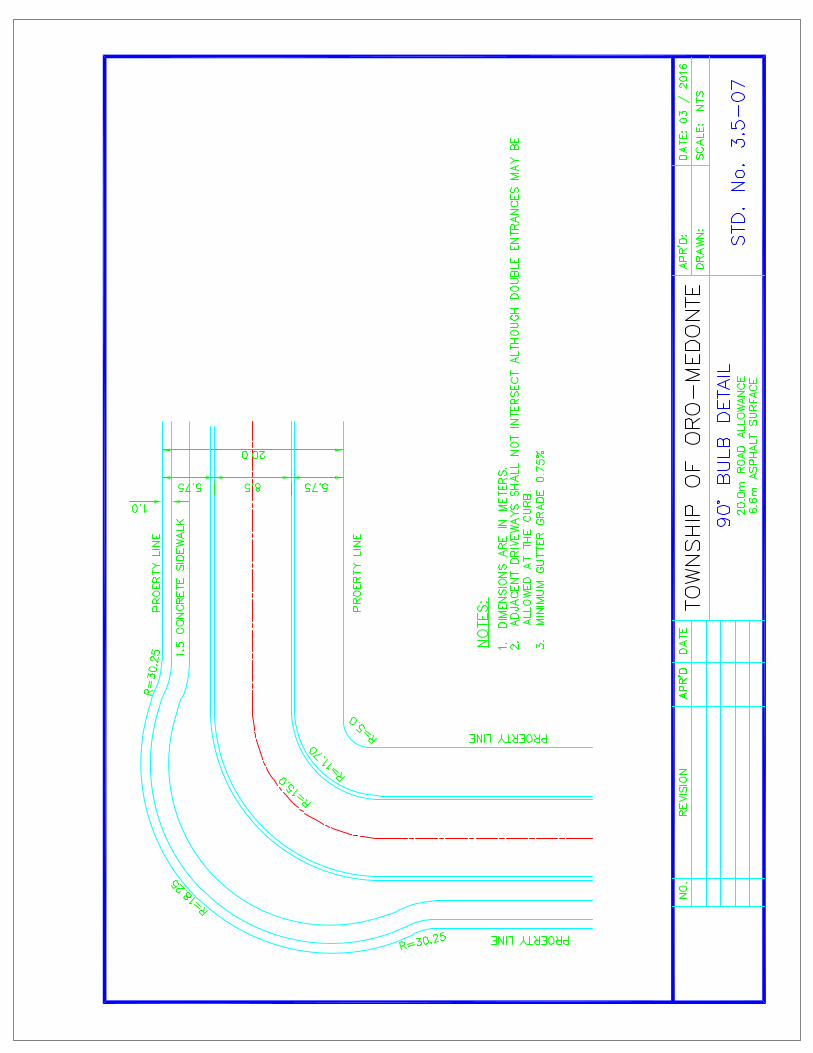

STD. No. 3.5-08 Local Collector and Industrial Road Right of Way (R.O.W.)
The Local Collector and Industrial Road classification requires the roadway to be
constructed to the following guidelines. (Heavy vehicles, wide loads and large traffic
volumes anticipated)
R.O.W. Width - 20.0m min.
Pavement Width - 9.0m min.
Shoulder Width - 0.9m asphalt min. (both sides) behind curb
Surface Type - 50 mm. compacted depth of HL8 Asphalt Base Course
- 40 mm. compacted depth of HL3 Asphalt Surface Course
Depth of Granular - Granular ‘A’: 150mm min
- Granular ‘B’ Type 1: 450mm min.
Additional depth may be required by site-specific geotechnical conditions. Drainage - As per O.P.S.S.
- Maximum ditch depth is 1.25m and a minimum of
150mm below subgrade. (Suburban)
Curb - Concrete barrier curb and gutter O.P.S.D. – 600.010
- Concrete mountable curb and gutter O.P.S.D. – 600.030
Entrance Culverts (Min.) - Ultra Rib, smooth wall, HDPE pipe
(as required) - 450mm min. diameter
Road Grades - 0.5% min to 6% maximum
Cross Fall - 2% for Surface
- 3% for Granular Base
Sub-drains - 150 mm min. diameter filter wrapped sub-drains shall
be installed. Exception to this requirement shall only be
considered with the appropriate recommendation by the
Developer’s Geotechnical Engineer.


STD. No. 3.5-10 Major Collector and Industrial Road Right of Way (R.O.W.)
The Major Collector and Industrial Road classification requires the roadway to be
constructed to the following guidelines. (Heavy vehicles, wide loads and very large
traffic volumes anticipated)
R.O.W. Width - 26.0m min
Surface Width - 15.0m
Surface Type - 45 mm. compacted depth of HL8 Asphalt Base Course
- 40 mm. compacted depth of HL8 Asphalt Binder Course
- 40 mm. compacted depth of HL3 Asphalt Surface Course
Depth of Granular - Granular ‘A’: 150mm min
- Granular ‘B’ Type 1: 450mm min.
Additional depth may be required by site-specific geotechnical conditions. Drainage - As per O.P.S.S.
- Maximum ditch depth is 1.25m and a minimum of
150mm below subgrade. (Suburban)
Curb - Concrete barrier curb and gutter O.P.S.D. – 600.010
- Concrete mountable curb and gutter O.P.S.D. – 600.030
Entrance Culverts (Min.) - Ultra Rib, smooth wall, HDPE pipe
(as required) - 450mm min. diameter
Road Grades - 0.5% min to 6% maximum
Cross Fall - 2% for Surface
- 3% for Granular Base
Sub-drains - 150 mm min. diameter filter wrapped sub-drains shall
be installed. Exception to this requirement shall only be
considered with the appropriate recommendation by the
Developer’s Geotechnical Engineer.


79
3.6 Erosion and Sediment Control Measures
Prior to commencement of any work on site, the Developer is required to implement an
Erosion and Sediment Control Plan (ESCP) consisting of a report and drawing(s) as
required, to be approved by the Township and appropriate Conservation Authority.
Erosion and sediment control measures shall be designed in accordance with OPSS
and additional requirements may be necessary where creek or stream crossings for
underground services, bridge or culvert construction across active streams, channel
diversions and outfalls to active streams are encountered. Plans shall outline measures
to reduce impact on the streams including the timing of construction activities to
minimize disruption as required by NVCA, LSRCA, MNR and DFO, where applicable.
The ESCP shall be designed and implemented in order to effectively reduce on-site
erosion and prevent off-site transport of silt, both overland and via the municipal storm
sewer system, or into treed and / or environmentally sensitive areas within or external to
the development. The ESCP shall include provision to minimize windblown dust and to
minimize and manage mud tracking on to adjacent roads.
All erosion and sediment controls are temporary measures constructed prior to other
site work which shall be maintained until assumption of the subdivision. Prior to
assumption of the subdivision all temporary measures shall be removed and all
disturbed areas stabilized.
All erosion and sediment control devices are to be inspected by the Developer’s
Consulting Engineer once per week and after each rainfall of 1 cm or greater to ensure
that they are in proper working condition. A permanent record of these inspections must
be forwarded to the Director of Engineering and Environmental Services within five (5)
days of inspection.

80
All disturbed ground left inactive shall be stabilized by seeding, sodding, mulching or
covering, or other equivalent control measure. The period of time of inactivity shall not
exceed thirty (30) days, unless otherwise authorized by the Director of Engineering and
Environmental Services.
All activities on the site shall be conducted in a logical sequence to minimise the area of
bare soil exposed at any one time.
3.6.1 ESCP Measures and Requirements
The ESCP must address specific requirements for each stage of construction as
follows:
• Tree removal
• Clearing and grubbing
• Topsoil stripping and rough grading
• Construction of services
• Road and building construction
All disturbed ground left inactive shall be stabilized by seeding, sodding, mulching or
covering or by other equivalent measure. The period of time shall not exceed 30 days
unless otherwise authorized by the Township.
The phasing of individual developments must be taken into account during the design of
the control measures including locations for topsoil stockpiles. A primary consideration
shall be to expose the least possible area of land for the shortest possible timeframe.
All installed erosion and sediment control measures shall be inspected by the
Developer’s Consulting Engineer once per week and after each rainfall of 1 cm or
greater.
Inspection reports shall be forwarded to the Director of Engineering and Environmental
Services within five (5) days of inspection.

81
3.6.1.1 Silt and Sediment Control Fence
Silt and Sediment Control Fence shall be installed along all down-slope sides of a site
along the edges of a drainage channel passing through the site, and along the
perimeter of all other areas sensitive to sediment accumulation.
Silt and Sediment Control Fence shall be installed wherever surface runoff drains onto
adjacent properties, completely around the base of topsoil stockpiles and along the
perimeter of all other areas sensitive to sediment accumulation (e.g. watercourses,
valleys, woodlots, areas to remain undisturbed etc.).
Silt and Sediment Control Fence shall be constructed in accordance with O.P.S.S.,
NVCA and/or LSRCA standards. Installations shall be specified as “Light Duty” or
“Heavy Duty” according to the application. All heavy-duty sediment control fences shall
be constructed in accordance with Township of Oro-Medonte Standard Drawings.
All Silt and Sediment Control Fence shall be inspected by the Developer’s Consulting
Engineer once per week and after each rainfall of 1 cm or greater and maintained on a
regular basis.
3.6.1.2 Topsoil Stockpile Protection
Runoff shall be controlled by Silt and Sediment Control Fence or other approved
measures and devices.
If the Stockpile is to remain for more than 30 days, Stockpiles shall be stabilized by
vegetative cover, or other means.
All Stockpiles containing more than 100m3 of material shall be located a minimum of
10m away from a roadway, drainage channel or an occupied residential lot.
The maximum side-slopes for topsoil stockpiles shall be 1.5 horizontal to 1.0 vertical.
The maximum Stockpile height shall be approved by the Township in consideration of
the surrounding land uses and duration the Stockpile is to be in place.

82
3.6.1.3 Temporary Sediment Basins
Sediment Basins shall be constructed on sites having a disturbed drainage area of
greater than two (2) hectares.
Temporary Sediment Basins may also be required for sites smaller than two (2)
hectares where water courses or environmentally sensitive areas have been identified
or those having an average slope greater than 12%.
Temporary Sediment Basins shall be designed to settle out particles that are 0.04 mm
in diameter or larger from surface water runoff and storm sewer flows and shall be sized
to meet LSRCA criteria of minimum 125 m3/ha, 24hr detention and 125 m3/ha
permanent pool storage volume or the ultimate pond criteria.
Temporary Sediment Basins are to have filter fabric / clear stone wrapped perforated
riser outfalls with anti-seepage collars and rip rap overflow weirs.
3.6.1.4 Catchbasin Sediment Control
All catchbasins shall be provided with a sediment control barrier.
Sediment removal is required when the depth from the underside of frame to top of the
accumulated sediment is reduced to 300mm.
Under appropriate drainage circumstances, all non-low point roadside catchbasins shall
be provided with sediment protection by double wrapping the catchbasin grate with a
woven geotextile.
All low point catchbasins must utilise alternative sediment control measures so that the
drainage outlet is not completely blocked.
Regular weekly cleanings of the sump or the use of sediment bag shall be undertaken
for these catchbasins.

83
All Catchbasin Sediment Controls shall be inspected by the Developer’s Consulting
Engineer once per week and after each rainfall of 1 cm or greater and maintained on a
regular basis.
3.6.1.5 Stone Pad Construction Entrance / Access (Mud Mat)
In order to reduce the tracking of mud onto a paved road, a pad of crushed stone shall
be constructed at the site entrance and exit leading onto any existing road. The stone
pad shall be a minimum of 450mm thick, 30m long and 5m wide. The first 15m from the
entrance/exit shall be constructed with 50mm clear stone. The remaining 15m shall be
constructed with 150mm riprap.
This stone pad must be maintained as required given the site conditions to ensure mud
tracking is kept to a minimum. In some cases the drawings shall specify a required truck
haul route.
3.6.1.6 Rock Check Dams
To be installed in swales and ditches in accordance with OPSD 219.210 and 219.211
where runoff drains to adjacent properties or to prevent silt and sediment migration
within the site as required.
3.6.1.7 Vegetative Buffer Strips
A minimum 3m wide vegetative buffer strip shall be provided along the limits of the
development adjacent to existing road boulevards and existing residential properties.
Where a sediment control fence is required, it shall be constructed in front of the buffer
strip.

84
3.6.2 Drawing and Report Requirements
3.6.2.1 Drawings
ECSP Drawings shall be comprised of, and include the following:
• Scale at 1:500 or 1:1000
• Location of buildings, existing and proposed, within and adjacent to the property
• All natural features within and adjacent to the property (woodlots, watercourses,
valley lands etc.)
• Trees to be preserved
• Existing contours at 0.5 m intervals
• Proposed interim and final elevations
• Areas to be disturbed
• Direction of overland flow
• Staging of construction and implementation of control measures
• Proposed erosion and sediment control measures (silt fence, check dams,
sediment basins, interceptor swales, stone mud mats, etc.)
• Topsoil stockpile locations with estimated quantities, max. height and side
slopes
• Detail drawings
3.6.2.2 Report
A brief report shall accompany the drawings which, at a minimum, outline staging of
construction and implementation of the proposed erosion and sediment control
measures, a description of measures to be undertaken, silt basin calculations, features
to be protected and an inspection and maintenance program.
The report shall also recommend measures to control dust such as road cleaning,
watering, work restrictions on windy days, minimizing disturbed areas and other
measures.


85
3.7 Stormwater Management
The Township has set out the following objectives for effective stormwater management
infrastructure design and construction:
• Prevent loss of life and minimize impact to adjacent properties
• Prevent inconvenience from surface ponding and flooding
• Prevent adverse impacts on the local groundwater systems and base flows in
receiving watercourses
• Prevent downstream flooding and erosion
• Prevent pollution discharges to watercourses
• Prevent soil losses and sediments to enter sewer systems and water bodies
from construction activity
• Prevent impairment of aquatic life and habitat
• Promote orderly development in a cost-effective manner.
Stormwater management requirements generally must reflect distinct solutions and vary
depending upon the watershed, and in some cases the storm sewer shed, that the site
is located. Site-specific requirements can be obtained from the Township. A stormwater
management report shall be required for all development applications.
Site specific stormwater management reports shall be consistent with all applicable
background reports prepared by the Township or Conservation Authority
(i.e. Watershed Planning Studies, Master Drainage Plans, Stormwater Management
Master Plan, etc.), including the Lake Simcoe Protection Plan and the Township of Oro-
Medonte Comprehensive Stormwater Master Plan.
Stormwater management designs must also be in accordance with NVCA or LSRCA
requirements and receive its approval, accordingly.
In general, stormwater management reports shall address the following:
• stormwater quantity and quality
• sediment and erosion control and base flow maintenance.

86
3.7.1 Quantity Control
The Township implements a Major and Minor system approach to stormwater
conveyance and control, comprised as follows:
Minor (convenience) System - 5 year return period – storm sewers, catch basins,
driveway culverts and surface swales.
Major (overland) System - 100 year return period – streams, valleys, man-made
channels, roadways, roadside ditches and ponds.
In general, quantity control measures are to be designed in accordance with the MOE
Stormwater Management Planning and Design Manual – March 2003 and / or the latest
version of NVCA or LSRCA criteria where applicable.
In addition to introducing pond storage into a stormwater management system,
increased flows resulting from increased impervious areas may be mitigated by utilizing
measures such as: discharging rainwater leaders onto grassed areas, providing
temporary rooftop and parking lot storage, or using grassed swales rather than piped
flow.
Other factors, such as snowmelt run-off with large volume and longer duration and
potential adverse downstream effects due to uncoordinated timing of peak flows must
be considered when designing stormwater management facilities.
Underground storage tanks and ‘super pipe’ systems for stormwater storage are
discouraged as part of the Township system due to inherent long term, high
replacement and maintenance costs and may only be considered in exceptional cases
and typically on in I.C.I. Site Plan developments.
Joint use facilities i.e. detention ponds over recreational playing fields and passive
parks, may be considered on an individual basis subject to suitably designed control
measures and the intended park use.

87
The degree of control on the quantity of run-off from a proposed development shall be
as follows:
• The post-development peak flow shall not be greater than the corresponding pre-
development peak flow for the 1:5 year, 1:10 year, 1:25 year and 1:100 year
storms. Other regulatory agencies may require other storm flows to be analyzed
(i.e. 2 year and/or Regional flows).
3.7.2 Runoff Quantity
• Rural Catchments – shall be modelled with OTTHYMO using the SCS 24 hr
design storm to generate peak flow value.
• Urban Catchments – shall be modelled with OTTHYMO using the Chicago 4 hr
design storm.
In general, the SCS Design Storms should be used for determining the hydrographs
for undeveloped / rural watersheds and for checking detention storages required for
quantity control.
The Chicago Design Storms should be used for determining hydrographs in urban
areas and also for checking detention storage. In most cases, the Developer’s
Consulting Engineer shall be required to run both sets of design storms to make sure
that the more stringent is used for each individual element of the drainage system (pipe
flow, road flow, channel flow, detention storage).
The time step for discretization of the design storm can vary according to the size of the
sub-watershed, but must not exceed the estimated time of concentration. The
maximum rainfall intensity should be compatible with that of real storms on record.
All parameter assumptions used in the OTTHYMO input shall be clearly identified in the
stormwater management report.

88
3.7.3 Quality Control
In general, water quality controls are to be designed in accordance with the MOE
Stormwater Management Planning and Design Manual – March 2003 or latest version,
the Lake Simcoe Protection Plan and NVCA or LSRCA criteria, as applicable.
Prior to initiating design, the Developer’s Consulting Engineering shall contact the
Township for acceptability of specific measures in consideration of long term
maintenance and effectiveness.
3.7.4 Watershed Area
The watershed area shall be determined from contour plans and shall include all areas
that naturally drain into the system and any fringe areas not accommodated in adjacent
storm drainage systems, as well as other areas which may become tributary by reason
of regrading. This information shall be confirmed with the Director of Engineering and
Environmental Services prior to the start of the design of the internal servicing of the
site.
3.7.4.1 External Catchment Areas
A plan shall be prepared to a scale of 1:1,000 to 1:2,000 dependent upon the size of the
watershed area, to show the nature of the drainage of the lands surrounding the
development site and to show all external drainage areas that are contributory to the
drainage system for the development. The external drainage areas shall be divided into
smaller tributary areas and the area and the location to which the tributary area is
considered to drain in the design shall be clearly shown. The plan shall clearly show all
existing contours used to justify the limits of the external drainage areas.
The uses as identified in the latest Zoning By-law and Official Plan shall be used to
determine the correct values of the run-off parameters for all external areas in the
design and to determine the specific areas to which these values apply in lieu of precise
information on development as a whole or any part of a watershed area.

89
This external drainage area plan shall be prepared and shall be submitted to the
Director of Engineering and Environmental Services at the functional report stage and
prior to the commencement of the detailed storm sewer design.
3.7.4.2 Internal Catchment Areas
An internal storm drainage plan shall be prepared to a scale of 1:1,000 and shall include
all roads, lots, blocks and other lands within the development. The proposed storm
sewer system shall be shown on this plan with all maintenance holes numbered
consecutively from the outlet. These maintenance holes shall be the tributary points in
the design and the area contributing to each maintenance hole shall be clearly outlined
on this plan. The area, in hectares, of each contributing area (to the nearest hundredth)
and the run-off parameter used shall be shown in a circle located within the contributing
area. In cases where areas of different run-off parameters may be tributary to the same
maintenance hole, the areas and the parameters shall be separately indicated on the
plan.
In determining the tributary area to each maintenance hole, the proposed grading of the
lots must be considered to maintain consistency in the design.
In the case of large areas under single ownership or blocks requiring future site plan
agreements, the design shall be prepared on the basis of the whole area being
contributory to one maintenance hole in the abutting storm sewer unless more than one
private storm connection is necessary to serve the property, in which case the
appropriate area tributary to each connection shall be clearly shown and taken into
account in the storm sewer design.
The storm drainage plan shall indicate but not be limited to the following:
• existing contours
• drainage patterns of adjacent lands
• runoff coefficients and areas (ha) of tributary areas outside the development and
for each section of the storm sewers within the development

90
• direction of runoff
• road names
• maintenance hole numbers
• sewer sizes, slope and directions of flow
• any catch basins or swales, on the lots or blocks, required to collect the runoff
• temporary or permanent quantity and quality stormwater management facilities
• major and minor overland flow routes
• culverts and other drainage appurtenances
3.7.5 Stormwater Pond Requirements
The design of stormwater management ponds shall be completed with consideration of
the following aesthetic and landscape design criteria:
• Stormwater management dry ponds shall be designed to limit the maximum
depth of water to 1.8 m above the lowest point of the stormwater basin. An
additional 0.3 m freeboard is required above the maximum flood level. The
maximum depth of the extended detention zone shall not exceed 1.0 m above the
lowest point of the pond.
• Maximum side slope shall be 5:1 from the bottom of the dry pond to the limit of
maximum extended detention, with a minimum horizontal length of 3.0 m. The
minimum allowable gradient on the bottom of the basin shall be 1.0% and the
maximum gradient shall be 5%.
• Stormwater management wetlands shall be designed to limit the maximum depth
of water to 2.1 m above the lowest point of the stormwater basin excluding
micropools. An additional 0.3 m freeboard is required above the maximum flood
level.
• The maximum depth of the extended detention zone shall not exceed
1.0 m above the permanent pool elevation. Maximum peak flow attenuation zone
shall not exceed 1.8 m above the permanent pool elevation.

91
• The permanent pool depth shall range between a minimum depth of 0.15 m to a
maximum depth of 0.45 m.
• A maximum 5:1 slope below the permanent pool level shall be permitted around
the entire stormwater management wetland. A maximum 5:1 slope above the
permanent pool level shall be permitted around the entire stormwater
management wetland. The slope shall extend from the permanent pool level, to
the limit of maximum extended detention. The horizontal distance of this slope
must be a minimum of 3.0 m.
• Stormwater management wet ponds shall be designed to limit the maximum
depth of water to 3.3 m above the lowest point of the stormwater basin. An
additional 0.3 m freeboard is required above the maximum flood level. The
maximum depth of the extended detention zone shall not exceed 1.0 m above the
permanent pool elevation. The permanent pool depth shall range between a
minimum depth of
1.0 m to a maximum depth of 1.5 m.
• A maximum 5:1 slope shall be permitted around the entire stormwater
management wet pond. The slope shall extend from the bottom of the
permanent pool to the limit of maximum extended detention.
• Where stormwater management facilities to be owned by the Township abut
private property, fencing shall be required at the discretion of the Township. At a
minimum, demarcation of property boundaries is required. Fencing, signage
and/or property demarcation shall be to Township Standards.
• In situations where existing natural areas are proposed to be used for stormwater
management, exemptions to the depth and slope criteria may be provided to
minimize disturbance to the natural feature, at the discretion of the Township.
• Designed pedestrian access areas shall not exceed a maximum slope of 12:1.
92
• Notwithstanding the above slope and depth criteria, in the case of headwall
design, the depth of water related to adjoining side slopes may vary and fencing
is required for safety purposes.
• Areas subject to the collection of contaminants or spills shall be fitted with
adequate oil / grit separators.
• Maintenance access requirements are to be determined on a site-by-site basis,
however, the following general criteria are recommended: Controlled
maintenance access routes shall be provided to both inlet and outlet structures
and forebays. A minimum 6.0 m wide surface to accommodate maintenance
vehicles within a minimum 10 m turning radius (inside radius) and a flat 10 m
loading areas is required. Maintenance access routes shall not exceed a
maximum slope of 10:1. The design of maintenance routes and loading areas
shall be to the approval of the Director of Engineering and Environmental
Services.
• Sediment drying area may be required adjacent to the forebay area to facilitate
dewatering of sediment prior to removal to an approved disposal location.
• Maintenance by-pass shall be provided via a maintenance hole upstream of the
entry to the pond to divert all flow from the pond during maintenance and
sediment removal procedures.
3.7.6 Storm Sewer Design
Storm sewers, designed and constructed in accordance with the most recent
requirements and specifications of the Township, shall be of adequate size and depth to
provide service for the development of lands within the upstream watershed and/or for
the drainage of any areas designated by the Township. Storm drainage shall be
directed to an outlet considered adequate in the opinion of the Township and applicable
agencies.

93
Channel works, bridges, culverts and all other drainage structures or works shall be
designed, approved and constructed in accordance with the most recent drawings and
specifications of all applicable agencies having jurisdiction, such as the Township,
LSRCA, NVCA, MOECC, MTO, MNR, DFO, etc.
3.7.6.1 Hydrology and Design Flows
Storm sewers shall be designed to drain all lands based on the Rational Method. The
Rational Method calculations must be checked using a model approved by the
Township where the drainage area is greater than 10 hectares. The larger of the flows
is to be used in the design of the sewer system unless approved otherwise.
Q = 0.0028 C I A where: Q = Flow in cubic metres per second
A = Area in Hectares
C = Run-off coefficient
I = Intensity in mm/hr
Storm sewers shall generally be designed to accommodate 1:5 year storm flows.
3.7.6.2 Intensity of Rainfall
The intensity of rainfall is to be determined from the Intensity-Duration-Frequency
values from the Atmospheric Environment Services Orillia Station.
Where I = A x tB and I is in mm/hr, t is time of concentration in hours; A and B are as
follows:
Storm Return Period A B
2 year 22.5 -0.728
5 year 29.9 -0.725
10 year 34.8 -0.724
25 year 40.9 -0.723
50 year 45.5 -0.722
100 year 50.0 -0.722

94
3.7.6.3 Time of Concentration
The minimum initial time of concentration is to be 10 minutes.
Pre-Development Areas:
To calculate the initial time of concentration (tc) for upstream, undeveloped lands, the
following formulas may be used: Bransby-Williams or Airport Method. The most
appropriate method shall be determined at the discretion of the Township.
3.7.6.4 Run-off Coefficient
The Developer’s Consulting Engineer shall submit calculations and drawings
(as required) to support the run-off coefficients used for storm sewer design with the
Rational Method.
In general, run-off coefficients shall be as follows:
Parks over 4 hectares 0.20*
Parks 4 hectares and under 0.25*
* Parks with increased impermeable area shall require a higher run-off coefficient.
Single-family Residential (Urban) 0.45
Single-family Residential (Suburban) 0.40
Semi-detached Residential 0.60
Townhouses, Maisonettes, Row Houses, etc. 0.70
Apartments 0.75
Schools and Churches 0.75
Industrial (local) 0.75
Industrial (urban) 0.90
Commercial 0.90
Heavily Developed Areas 0.90
Paved Areas 0.95
A minimum run-off coefficient of 0.55 is to be used for undeveloped upstream area
where future residential development is expected and 0.75 where future industrial, high-
density residential or commercial development is expected.

95
3.7.6.5 Drainage Area
Drainage systems shall be designed to accommodate all upstream drainage areas
considering interim and ultimate conditions.
3.7.7 Pipe Sizing and Specifications
3.7.7.1 Pipe Capacities
Manning’s formula shall be used in determining the capacity of all storm sewers. The
capacity of the sewer shall be determined on the basis of the pipe flowing full.
The value of the roughness coefficient ‘n’ used in the Manning’s formula shall be as
follows:
• concrete pipe 0.013
• concrete box culverts 0.013
• corrugated metal 68 x 13mm corrugations 0.024
• corrugated metal 25% paved invert 0.021
• PVC pipe 0.013
• HDPE smooth wall ribbed pipe 0.013
3.7.7.2 Flow Velocities (Flowing full)
For circular pipes the minimum acceptable velocity is 0.8 m/s and the maximum
acceptable velocity is 3.5 m/s during the 5 year storm event.
3.7.7.3 Minimum Sizes
The minimum size for an on-street storm sewer shall be 300 mm diameter.

96
3.7.7.4 Minimum Grades
Regardless of flow velocities obtained, the minimum design grades for pipe storm
sewers shall be as follows:
Sewer Size (diameter) Minimum Grade
≤ 375 mm 0.40%
450 mm ≤ 525 mm 0.30%
600 mm ≤ 1200 mm 0.20%
> 1200 mm 0.15%
3.7.7.5 Depth of Storm Sewers
The depth of a deep storm sewer shall be sufficient to provide a suitable outlet for the
building foundation weeping tiles. The minimum cover to the top outside pipe barrel of a
deep storm sewer shall generally be 2.5 to 3.0 metres. The minimum cover to the top
outside pipe barrel of a shallow storm sewer system shall not be less than 1.5 metres
from the centre-line of the roadway unless alternate measures are implemented as
approved by the Township.
3.7.7.6 Location
The storm sewers shall be located as shown on the standard Township road cross-
section drawings. This standard location shall be generally 2.1 metres north or east of
the centreline of the road allowance. In the case of crescents, looped and curvilinear
roads, this standard location may be varied to the extent that the storm sewer remains
on the same side of the centreline of the road (i.e., left or right) to avoid crossing the
sanitary sewer trenches at the changes in direction of the road.

97
3.7.7.7 Pipe Crossings
A minimum clearance of 0.20 metres shall be provided between the outside of all pipe
barrels at all points of crossing. In cases where the storm sewer crosses a recent utility
trench at an elevation higher than the elevation of the utility, a support system shall be
designed to prevent settlements of the storm sewer, or alternatively the original trench
shall be re-excavated to the top of the utility and shall be backfilled with non-shrinkable
fill (low strength concrete) to adequately support the storm sewer. When the storm
sewer passes under an existing utility, adequate support shall be provided for the utility
during and after construction to prevent damage to that utility.
3.7.7.8 Radius Pipes
Radius pipe shall be allowed for storm sewers 1050 mm in diameter and larger provided
that a maintenance hole is located at the beginning or at the end of the radial section.
The minimum centre line radius allowable shall be in accordance with the minimum radii
table as provided by the pipe manufacturer.
3.7.7.9 Limits of Construction
Sewers shall be terminated with a maintenance hole at the upstream subdivision limits
when external drainage areas are considered in the design. The design of the terminal
maintenance holes must allow for the future extension of the sewer.
When external areas are not included in the sewer design, the sewer shall extend at
least half way across the frontage and/or flankage of any lot or block in the subdivision.
3.7.7.10 Sewer Alignment
Storm sewers shall be laid in a straight line between maintenance holes unless radius
pipe has been designed. Joint burial (common trenching) with sanitary sewers may be
considered when supported by the recommendations of a soils report prepared by the
Developer’s Geotechnical Engineering Consultant.

98
3.7.7.11 Changes in Pipe Size
No decrease of pipe size from a larger size upstream to a smaller size downstream
shall be allowed regardless of the increase in grade.
3.7.7.12 Pipe Material Classification and Bedding
All storm sewer mains shall generally be constructed of reinforced concrete with
suitable strength class recommended by the Developer’s Consulting Engineer. Smooth
wall ribbed PVC may be used for mains up to 900 mm diameter. Storm sewer leads
from catch basins shall be constructed with non-reinforced concrete pipe or PVC pipe.
The class of pipe and the type of bedding shall be selected to suit loading and proposed
construction conditions. For rigid pipe, Class B bedding (compacted Granular A bedding
and cover over the sewer) in accordance with OPSD shall be used.
Embedment for flexible pipe shall be Granular A in accordance with OPSD.
Alternate granular materials for pipe bedding may be specified, subject to the approval
of the Township, however clear stone bedding is generally not permitted. In areas
where it is difficult to control the infiltration of ground water into the sewer trenches clear
stone bedding may be considered provided it is completely wrapped in a suitable
geotextile, selected and installed in accordance with the manufacturer’s requirement.
The width of trench at the top of the pipe must be carefully controlled to ensure that the
maximum trench width is not exceeded unless additional bedding or higher strength
pipe is used. Where poor soil conditions and high ground water levels are present, the
Consulting Engineer shall prepare special designs for the Township’s approval.
Reinforced concrete pipe shall conform to the requirements of OPSS 1820.
Polyvinyl chloride (PVC) pipe products shall conform to the requirements of
OPSS 1841. The pipe must be manufactured with factory assembled spigot
gasket and integral bell joints.
Polyethylene pipe products shall conform to the requirements of OPSS 1840.

99
3.7.8 Maintenance Hole Requirements
Maintenance holes must be precast concrete and shall be designed and constructed in
accordance with the most recent OPSS and OPSD. Where the standard drawings are
not applicable, the maintenance holes shall be individually designed and detailed.
3.7.8.1 Location and Spacing
Maintenance holes shall be located at each change in alignment, grade or pipe material,
at all pipe junctions, at the beginning or end of all radius pipe sections and at intervals
along the pipe to permit entry for maintenance to the sewer.
3.7.8.2 Maximum Spacing
The maximum spacing between maintenance holes shall be as follows:
Pipe Size (diameter) Maximum Maintenance Hole
≤ 600 mm 100
675 mm ≤ 1200 mm 120
> 1200 mm 150
3.7.8.3 Maintenance Hole Design
• Minimum size of maintenance holes to be 1500 mm diameter.
• All maintenance hole chamber openings shall be located on the side of the
maintenance hole parallel to the flow for a straight run maintenance hole, or on the
upstream side of the maintenance hole at all junctions.
• The change in direction of flow in any maintenance hole shall not be permitted at
acute interior angles.
• Safety gratings shall be provided in all maintenance holes when the depth of the
maintenance hole exceeds 5 m. The maximum spacing between safety gratings
shall not exceed 5 m.
• The obvert(s) on the upstream side of a maintenance hole shall not be lower than
the obvert of the outlet pipe.

100
• The maximum change in direction of flow in maintenance hole, for sewer sizes 1050
mm diameter and over, shall be 45°.
• Where the difference in elevation between the obvert of the inlet and outlet pipes
exceeds 0.6 m, a drop structure shall be placed on the inlet pipe.
• All storm sewer maintenance holes shall be benched to the obvert of the outlet pipe
for pipe sizes 600 mm or less and to the spring line of the outlet pipe for pipe sizes
675 mm and greater.
• The minimum width of benching in all maintenance holes shall be 230 mm.
• All maintenance holes and catch basin structures shall have frost straps in
accordance with OPSD 701.100.
• Maintenance holes in boulevards shall be located, wherever possible, a minimum of
1.5 m from the face of curb or other service.
• Minimum size of any maintenance hole stack shall be 685 mm square.
3.7.8.4 Elevations for Maintenance Hole Frames and Covers
All maintenance holes, located within the travelled portion of a roadway, shall have the
rim elevation set flush with the surface of the base course asphalt. The concreting and
setting of the frame and cover shall be completed in accordance with the details
provided in the standard drawing. A maximum of 300 mm of modular rings shall be
permitted on maintenance holes in new subdivisions. No concrete shall extend over the
edge of the maintenance hole.
Prior to the placement of the final lift of asphalt, maintenance hole frames shall be reset
to final elevations.
3.7.8.5 Head Losses and Drops
Suitable drops shall be provided across all maintenance holes to compensate for the
loss in energy due to the change in flow velocity and for the difference in the depth of
flow in the sewers.

101
In order to reduce the amount of drop required, the designer shall, wherever possible,
restrict the change in velocity between the inlet and outlet pipes to 0.6 metres/sec.
Hydraulic calculations shall be submitted for all junction and transition maintenance
holes on sewers where the outlet is 1,050 mm or greater. In addition, hydraulic
calculations may be required for maintenance holes where the outlet pipe is less than
1,050 mm dia. if, in the opinion of the Township, there is insufficient invert drop provided
across the maintenance hole.
Regardless of the invert drop across a maintenance hole as required by calculation, the
obvert of the outlet pipe shall not be higher than the obvert of the inlet pipe in any
maintenance hole.
The minimum drops across maintenance holes shall be as follows:
Change in Direction Minimum Drop (mm)
Straight run 30
≤ 45° 50
> 45° ≤ 90° 80
3.7.8.6 Frame and Grate
All maintenance hole frames shall be as per OPSD 401.010 with Type A closed cover
labeled Storm.
3.7.9 Catch Basin Requirements
3.7.9.1 Location and Spacing
Catch basins shall be selected, located and spaced in accordance with the conditions of
design. The design of the catch basin location and type shall take into consideration the
lot areas, the lot grades, pavement widths, road grades and intersection locations.
All catch basins and their leads shall be of the single or double type. To ensure that the
capture or inlet capacity matches that of the storm sewer, the spacing of catch basins
on roads may be varied.

102
If detailed analysis of the major-minor system and SWM analysis of the pipe system
indicate the need for inlet controls, additional constrictions should be implemented.
Since reduction in the size of the standard catch basin covers is not desirable, an orifice
plate can be located in the catch basin. This is applicable to private development only.
Orifice plates are not permitted within the Township right-of-way.
Catch basins shall be generally located upstream of sidewalk crossings at intersections
and upstream of all pedestrian crossings.
Catch basins shall not be located in driveway curb depressions.
Double catch basins shall be required when the catch basin intercepts flow from more
than one direction.
Rear yard catch basins shall be eliminated whenever possible.
Maximum spacing for catch basins including cul-de-sac gutters shall be as follows:
Pavement Width (m) Maximum Spacing (m)
≤ 4% Grade > 4% Grade
≤ 8.5 90 60
> 8.5 ≤ 9.8 80 55
> 9.8 ≤ 12.2 75 50
> 12.2 60 40
3.7.9.2 Catch Basin Types
Catch basins must be pre-cast concrete and shall be designed and constructed in
accordance with the most recent OPSS and OPSD.
Special catch basins and inlet structures shall be fully designed and detailed by the
Developer’s Consulting Engineer.
Double catch basins are to be installed at the low point of any road.
103
3.7.9.3 Catch Basin Leads
For single catch basins, the minimum size of connection shall be 300 mm diameter and
the minimum grade shall be 1.0%.
For double catch basins, the minimum size of connection shall be 375 mm diameter and
the minimum grade shall be 1.0%.
For rear lot catch basins, the minimum size of the connection shall be 300 mm diameter
and the minimum grade shall be 1.0%.
In general, catch basins located in close proximity to a maintenance hole shall have
their leads connected to the maintenance hole. Catch basin leads may not exceed
30.0 m when connected to the maintenance hole or sewer. Alternatively, a longer lead
can be connected to the sewer and a 1200 mm diameter maintenance hole / catch
basin used in lieu of the normal 600 mm. square catch basin.
3.7.9.4 Frame and Grate
The frame and cover for catch basins in roadway or walkway areas shall be as detailed
in OPSD 400.030.
Catch basins located in grassed areas shall have a Birdcage Grate per OPSD 400.120.
3.7.9.5 Catch Basins at Intersections
All catch basins at road intersections shall be located on the tangent section of the curb
at a minimum of 0.6 metres distant from the beginning or the end of the radial portion of
the curb.
3.7.9.6 Elevations for Catch Basin Frames and Grates
All catch basins located within the travelled portion of a roadway, shall have the frame
elevation set flush with the surface of the base course asphalt.

104
The adjusting and setting of the frames and grates shall be completed in accordance
with the details provided in OPSD 704.010 upon placement of surface course asphalt.
Temporary asphalt curbing shall be placed behind all catch basins within the travelled
portion of the roadway at the stage of base course asphalt. Asphalt curbing shall be
placed in accordance with OPSD 601.010 - Type “D”, between the two adjacent
expansion joints.
Prior to placing surface course asphalt, temporary asphalt curbs shall be removed and
replaced by concrete curb.
3.7.10 Downspouts, Foundation Drains and Storm Connections
3.7.10.1 Downspouts
Downspouts on all single family, semi-detached and townhouse residential units shall
be discharged onto grassed or garden areas and away from wells or tile bed areas.
Downspouts shall not encroach over / onto other adjacent private lands.
Splash pads of a hardened impervious material shall be placed at each Downspout.
Downspouts from all commercial, industrial, institutional and high density residential
buildings should be discharged onto grassed or garden areas, if possible and if
acceptable to the Township.
3.7.10.2 Foundation Drains
The Township requires that a sump pump system be installed in every building.
In every case, the underside of footing shall be set above the seasonal high ground
water level, as determined in the geotechnical report.
Where sump pumps are installed in residential developments with open ditches, sump
pump discharges shall not be placed within the Township’s ditch lines of the road
allowances.

105
In no case shall sump pump discharge pipelines be connected to a storm sewer
system.
Sump pump discharges shall be directed to rear or side yard drainage swales and shall
not discharge onto driveways, walkways or over top of septic holding tanks.
3.7.11 Channel, Culvert and Overland Flow
For channel, culvert, bridge and/or erosion control projects the proponent is responsible
for obtaining all necessary approvals from the governing agencies, such as the NVCA,
LSRCA, MNR, DFO and/or MOECC.
3.7.12 Culverts and Bridges
3.7.12.1 Culvert and Bridge Hydraulic Capacity
Only arterial and collector roads should, if feasible, be permitted to cross the major
system watercourses. It is also recommended that designers consider the need to
design culverts and bridges on such arterial and collector roads for at least the 1:100
year storm flow, if not for the Regional Storm flow. If smaller culverts or bridges are pro-
vided, the backwater effects for the 1:100 year and Regional Storm flows must be
determined. Concrete box culverts shall be designed and placed for all watercourse
crossings subject to the approval of the Township. MNR, DFO, NVCA and/or LSRCA
approval may be required for watercourse/valley crossings under their regulations.
Road Classification Design Flood Frequency
Arterial 1:100 Year to Regional
Collector 1:50 Year
Urban Local 1:25 Year
Rural Local 1:25 Year
Temporary Detour 1:10 Year
Driveway 1:5 Year
NOTE: All culverts must be of sufficient length to provide for a preferred
5:1 (minimum 3:1) slope off the driving surface to the ditch invert.
106
All driveway culverts must be at least 7.0 m long and require a Driveway Entrance
Permit and approval. Driveway width to conform to Zoning By-law requirements, if
applicable.
Driveway culverts are to be minimum 2.0 m from hydro poles and utility boxes.
Bridges and other major drainage structures shall require special designs as determined
by the Township. Hydraulic calculations shall be required.
The frequency and magnitude of flooding or erosion shall not be increased on upstream
or downstream properties.
3.7.12.2 Open Channels
The proposed criteria for an open channel design shall be submitted to the Township for
approval prior to the actual design being undertaken. Open channels shall be defined
as major system overland flow channels, minor system outfall channels or natural
channels. Major system overland flow channel designs may be required to
accommodate the Regional Storm or the 100-year storm for new development.
The Developer’s Consulting Engineer shall also be responsible for obtaining the
approval of the design from the MNR, DFO, NVCA, LSRCA and the MOECC, if the
open channel concept is favourably considered.
Natural Channel design criteria shall be determined on a site by site basis.
The following guidelines must be considered:
Open Channels Minimum
Maximum
Grass lined – Natural 0.7 m/s 1.5 m/s
Grass lined – Maintained 0.7 m/s 1.5 m/s
Gabion lined 0.7 m/s 2.5 m/s
Concrete lined 0.7 m/s 4.0 m/s

107
3.7.12.3 Watercourse Erosion and Bank Instability
Where erosion or bank instability is already evident in an area to be developed or re-
developed, the Township requires that the situation be stabilized by appropriate
remedial measures. Where development may potentially cause significantly increased
downstream erosion, the Township shall require the Developer to mitigate further
damage by appropriate remedial and preventative measures.
Where designing remedial erosion or bank stabilization works, preservation of the
watercourse dynamics and natural valley aesthetics must be secondary only to
achieving a sound technical solution. The proposed design shall reference the MNR
Natural Channel Design Manual. A normal bank flow channel has a capacity of about
the 1:2 year flood. Protection to this level shall be adequate provided care is taken to
prevent any damage by higher floods and provided that the channel bank is not
coincident with a higher valley bank. In this latter case, it may be necessary to protect
the bank to a level as high as the 1:100 year flood or even the flood resulting from the
Regional Storm.
The proposed criteria for an erosion or bank stability design shall be submitted to the
Conservation Authority and / or Township for approval prior to the actual design being
undertaken.
3.7.12.4 Floodline Calculations
All floodline calculations are to be performed by a recognized engineering method and
are to conform to the Ministry of Natural Resources Flood Plain Management in Ontario
Technical Guidelines in consultation with the Township.
An acceptable method would include the HEC 2 computer model.
All supporting documentation is to be included in the submission including a hard copy
of the computer printout and a digital copy containing all input and output files.

108
3.7.12.5 Overland Flow Routes
An overland flow route continuous to the nearest major channel must be established
through all areas and shall be contained within either the road right-of-way or by
easements.
If the overland flow route travels across downstream property not municipally owned,
the developer must obtain the necessary agreement(s) from downstream owner(s)
accepting the increased quantity of runoff.
The depths of flooding permitted on roads and at intersections during the 1:100 year
storm are as follows:
• no building shall be inundated at the ground line, unless the building has been
flood proofed
• for all classes of roads, the depth of water at the gutter shall not exceed 0.3 m.
Flow across road intersections shall not be permitted for minor storms (generally 1:10
year). To meet the criteria for major storm run-off, low points in roads must have
adequate provision for safe overland flow.
3.7.13 Inlet / Outlet and Special Structures
Inlet and outlet structures shall be fully designed on the engineering drawings. The
details provided shall include the existing topography, proposed grading and the work
necessary to protect against erosion.
3.7.13.1 Inlets
Inlet structures shall be fully designed by the Developer’s Consulting Engineer should
OPSD structures are not deemed suitable. Inlet grates shall generally consist of inclined
parallel bars or rods set in a plane at approximately 180 degrees with the top away from
the direction of flow. Gabion, riprap or concrete shall be provided at all inlets to protect
against erosion and to channel the flow to the inlet structure.

109
Hydraulic design calculations for inlet structures must be performed in accordance with
guidelines established by the Ministry of Transportation Drainage Manual.
The design of any culvert on a new or reconstructed watercourse where an inlet grating
is required must provide a measure of safety and minimize the risk of entanglement or
entrapment of a person. As well, grating shall be designed to prevent debris from
entering the stormwater system.
3.7.13.2 Outlets
The OPSD headwall standards shall be used for all storm sewers up to 2,400 mm
diameter. For sewers over 2,400 mm the headwalls shall be individually designed.
All headwalls shall be equipped with a grating over the outlet end of the pipe and a
railing across the top of the headwall for the protection of the public.
Outfall grates shall consist of horizontal bars or rods spacing shall not exceed 150 mm
clear. All metal parts from inlet/outlet grates to be protected from rusting.
All outlets shall blend in the direction of flow of the watercourse with the directional
change being taken up in the sewer rather than the channel.
Storm sewer outfalls shall not be connected to existing or proposed road crossing
culverts.
Storm sewer outfalls must be terminated at separate headwall structures, adjacent to
the outlet side of road crossing culverts.
Gabions, Terra-fix blocks, riprap, concrete or other erosion protection shall be provided
at all outlets to prevent erosion of the watercourse and the area adjacent to the
headwall.

110
The extent of the erosion protection shall be indicated on the engineering drawings and
shall be dependent upon the velocity of the flow in the storm sewer outlet, the soil
conditions, the flow in the existing watercourse and site conditions.
3.7.14 Storm Sewers – As-constructed Drawings
All actual storm system invert elevations shall be indicated on the As-constructed
drawings. If the difference is greater than 150 mm from the design vertical alignment,
affected portions of the sewer or overland drainage route shall be redrawn in profile.
Any maintenance hole which differs from the proposed horizontal location by more than
1.50 m shall be redrawn in both plan and profile.
In addition the following shall be indicated on the As-constructed drawings:
• pipe/culvert size, grade, type, class;
• chainage from MH along main to service tees.
NOTE: If as-constructed grade of sewer differs by more than 1% of the design grade,
the Developer’s Consulting Engineer shall submit revised hydraulic calculations.
3.7.15 Testing and Acceptance
A CCTV inspection (including flushing) as per OPSS 409 shall be conducted upon
satisfactory completion of all other testing, prior to the Township’s recommendation for
issuance of “Substantial Completion” and prior to the placement of surface course
asphalt. A CCTV inspection (including flushing) shall also be required prior to the
issuance of “Final Acceptance” if 18 months have lapsed since the placement of surface
course asphalt.


STORM WATER MANAGEMENT MINIMUM DESIGN CRITERIA
OBJECTIVE
PRELIMINARY DESIGN – B.M.P. (1)
FINAL DESIGN
APPROVALS REQUIRED
WATER /HABITAT SENSITIVITY
CONSTRUCTION MITIGATION SYSTEM
PERMANENT SYSTEM DESIGN
BUFFER FLOOD CONTROL MAJ0R SYSTEM
RUNOFF CONTROL PRE/POST
STORM SYSTEM (MINOR)
QUALITY CONTROL B.M.P. (1)
CONSTRUCTION MITIGATION
PERMANENT FACILITY
NON Quality & construction concerns only
- Erosion & sediment control (2) - 2 yr. storm, 1 hr. detention - Ponds - storage – 125 m
3/ha
- overflow – 5 yr. storm - retain particles > 40 microns - length to width ratio of 3:1 - Stabilization prior to winter
MTO/MOE Standards (2) - 5 yr. pre/post - 100 yr. flood - Integrate with watershed plan (3)
15 metres (5)
100 yr.
5 yr.
5 yr.
Aesthetics See (1) and (4)
- Site plan condition - No C of A - Agencies concur - Contingency plan
- Transfer Program C of A
NORMAL Quality & Quantity concerns
- 24 mm rainfall - Ponds - storage – 125 m
3/ha
- overflow – 5 yr. storm - retain particles > 40 microns - length to width ratio of 3:1 - Stabilization prior to winter - Erosion & sediment control (2)
Quantity 5 – 10 yr. pre/post 100 yr. flood Quality - 24 mm rainfall - Ponds – see construction mitigation - Integrate with watershed plan (3)
15 metres for quantity (5) 30 metres for quality (5)
100 yr.
5 – 10 yr.
5 yr.
Warm fish, cold fish, rec. uses see (1) and (4)
- Site plan condition - No C of A - Agencies concur - Contingency plan
- Transfer Program C of A
SENSITIVE Stressed habitat & water use concerns Policy 2
- Enhanced control erosion & sediment (2) - Phasing & restoration - Limited & restrictive - Ponds – enhanced design
Quantity 5 – 25 yr. pre/post 100 yr. flood Quality - Receiving water assessment - Retain up to 90% particles by wt. - Integrate with watershed plan (3)
30 metres for quantity (5) 30 metres for quality (5)
100 yr.
5 – 25 yr.
5 yr.
See (1) Habitat concerns enhanced measures
- C of A - Site plan condition - Contingency plan
C of A (MOE)
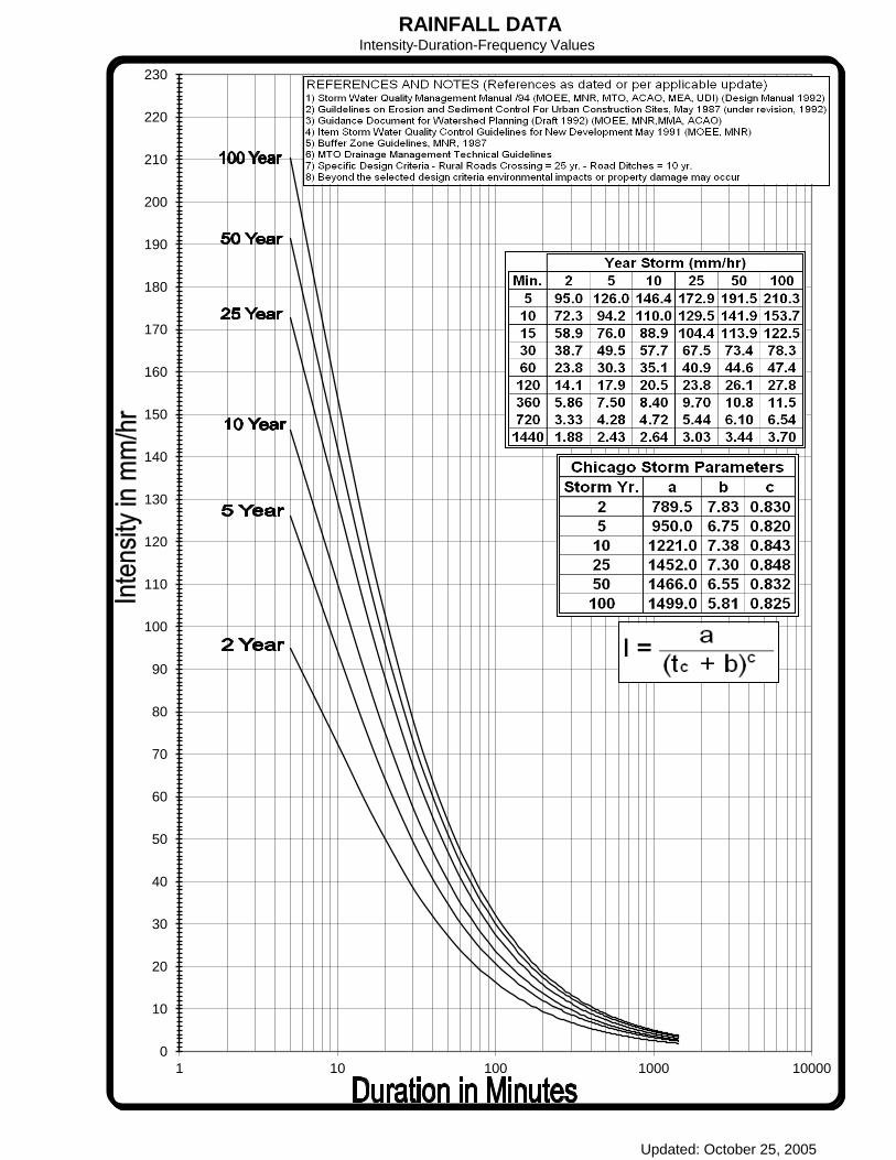
RAINFALL DATAIntensity-Duration-Frequency Values
0
10
20
30
40
50
60
70
80
90
100
110
120
130
140
150
160
170
180
190
200
210
220
230
1 10 100 1000 10000
Updated: October 25, 2005

111
3.8 Water Supply Distribution
Watermain shall be designed and constructed in accordance with the most recent
requirements and specifications of the Township.
Watermain shall be of adequate size to provide service for the development of adjacent
lands designated by the Township.
Prior to the commencement of any design for new watermain within the Township, the
applicant shall obtain confirmation from the Township that adequate water supply exists
for the development proposed.
3.8.1 Watermain Design Criteria
All watermain shall be sized to meet the greater of: the maximum daily demand plus
fire flow or the maximum hourly demand and fire flow.
3.8.1.1 Watermain Pressure
The maximum sustained operating pressure shall not exceed 700 kPa (101.5 psi). If
pressure in a localized area is above this level, a pressure-reducing valve shall be
installed on each service connection within that area or as a design consideration to be
included within the main.
Under normal conditions of maximum day demand, the pressure shall not drop below
275 kPa (40 psi) at any point in the water system.
Under conditions of simultaneous maximum day and fire flow demands, the pressure
shall not drop below 140 kPa (20 psi) at any point in the water system.

112
3.8.1.2 Friction Factors
The following “C’ values shall be used in the Hazen-Williams equation, for the design of
water distribution systems regardless of pipe materials.
Pipe Diameter (mm) C-Factor
150 100
200 to 300 110
400 to 600 120
Over 600 130
The above C-factors represent long-term values. A C-factor of 140 shall be used to
calculate maximum velocities for transient pressure estimations, or for checking pump
motor sizes for runout conditions.
In evaluating existing systems for expansion, the C-factors shall be determined by
actual field tests, wherever possible.
The Hazen-Williams equation shall be used to calculate the flow in watermain as
follows:
Q = 0.84918 (C) (A) (R)0.63 (S)0.54
Where: Q = Discharge (m3/sec.)
C = Coefficient of Roughness
A = Cross-Sectional Flow Area (m2)
R = Hydraulic Radius (m)
S = Slope of Energy Grade Line (m/m)

113
3.8.1.3 Domestic Demand
Domestic water demand shall be calculated on the basis of an average day
consumption rate of 450 litres per capita per day.
The maximum day and peak hour factors shall be determined from the latest MOECC
design guidelines although the following are considered minimums:
Maximum daily demand factor: 2.0
Peak hourly demand factor: 4.5
Peak flows other than domestic flows shall be determined on an individual basis.
3.8.1.4 Commercial and Institutional Water Demands
An average day flow of 28 cu.m. per hectare per day shall be used for design purposes
to estimate the water consumption for large commercial areas unless more specific data
is available.
When specific planning information is available, water consumption for individual
commercial and institutional sites may be calculated from the following table:
Use Water Usage
Shopping Centers 2500 - 5000L/1000 m2/day
Hospitals 900 -1800 L/bed/day
Schools 70 - 140 L/student/day
Campgrounds 225 - 570 L/campsite/day
The peak water usage rates in campgrounds varies with the type of facilities provided
(showers, flush toilets, clothes washers, etc.) and the ratio of these facilities to the
number of campsites. A peak rate factor of 4 shall be used. This factor shall be applied
to the average expected water usage at full occupancy of the campsite.

114
3.8.1.5 Industrial Water Demands
An average design flow of 36 cu.m. per hectare per day shall be utilized for design
purposes to estimate the average consumption rate for industrial areas unless more
specific data is available.
3.8.1.6 Fire Flows
The requirements for fire flows shall be discussed and agreed upon with the Director of
Engineering and Environmental Services and the Fire Department prior to proceeding
with detailed design.
The Water Supply Distribution system shall be designed and constructed to meet the
requirements of NFPA 24.
3.8.2 Selection of Watermain Sizing
For all watermain designed to carry fire flows, the following minimum sizing for
watermain shall apply:
For Residential areas 150 mm diameter
For Commercial areas 200 mm diameter
For Industrial areas * 300 mm diameter minimum
* To be sized according to the anticipated water demand.
In general, the following standardized watermain sizes shall be used in the Township:
150 mm, 200 mm, 300 mm, 400 mm, 500 mm, 600 mm
3.8.3 Depth of Watermain
Curb and Gutter Roads - 1.7 m minimum to obvert, measured below finished centre
line road grade.
Open Ditch Roads - The cover over the watermain and the service connections
shall not be less than 1.7 metres.

115
Unimproved Roads - 1.7 m minimum to obvert, measured below a future design
centre line road grade.
Watercourses, Creek - Adequate frost protection shall be provided below stream
bed. Generally 1.7 m minimum to obvert, measured below
the watercourse invert shall be considered acceptable.
3.8.4 Location of Watermain
Watermain shall be located as shown on the standard Township road cross-section.
This location shall generally be on the north or west sides of the road.
3.8.4.1 Horizontal Separation of Watermain and Sewers
Under normal conditions watermain shall be designed with a minimum clear horizontal
separation of at least 3.0 m from any sewer or sewer maintenance hole. The distance
shall be measured from the nearest edges of the pipes or structures.
3.8.4.2 Separations of Watermain and Sewers – Special Conditions
Under unusual conditions (where a significant portion of the construction shall be in
rock, or where congestion with other utilities shall prevent a clear horizontal separation
of 3.0 m) a watermain may be laid closer to a sewer, provided the elevation of the crown
of the sewer is a least 0.5 m below the invert of the watermain. Such separation shall
consist of in-situ material or compacted native earth backfill.
In rock trenches, facilities shall be provided to permit drainage of the trench to minimize
the effect of the impounding of surface water and/or leakage from sewers in the trench.
3.8.4.3 Watermain Crossing Sewers
Under normal condition watermain shall cross above sewers with at least 0.5 m vertical
separation.
When it is not possible for the watermain to cross above the sewer main, the watermain
passing under a sewer shall be protected as follows:

116
A vertical separation of at least 0.50 m shall be provided between the outside face of
the sewer and the top of the watermain.
The sewer shall be adequately supported to prevent excessive deflection of joints
and settling.
The length of watermain pipe under the sewer shall be centered at the point of
crossing so that the joints shall be equidistant and as far as possible from the sewer.
Watermain pipe joints shall be located 1.5 metres (minimum) from the centreline of
the sewer (both sides).
3.8.4.4 Utility Crossings
Watermain crossing over or under other utilities shall be designed with a 300 mm
minimum clear separation between the outside edges of the watermain and the utility.
3.8.4.5 Dead-Ends
Water distribution systems shall be designed in grid patterns or looped to avoid dead-
end sections.
Minimum pipe size and material for loops shall be 150 mm diameter PVC or designed in
accordance with a specific location at the discretion of the Township.
3.8.4.6 Extra Mains and Extra Fittings
No roadway leading out of a subdivision shall be completed and accepted by the
Township until connecting watermain are installed complete to the subdivision limits.
Extra fittings shall be installed at any point on the watermain requested by the Township
to provide for future connections.
3.8.5 Pipe Classification and Bedding
Acceptable materials for watermain pipe up to and including 300 mm diameter are as
follows:
Polyvinyl Chloride Pipe (PVC) manufactured in accordance with the latest edition
of CSA B137.3. A minimum Class 150, DR 18 pipe shall be used.

117
Fittings shall be of cast iron or ductile iron; cement lined and shall be manufactured to AWWA C110. All fittings shall be supplied with mechanical joint ends.
Polyethylene pressure pipe shall be to OPSS 1842.
19 mm dia. residential services shall be polyethylene pipe.
The class of pipe and the type of bedding shall be selected to suit loading and proposed
construction conditions. Pipe bedding and cover shall be homogeneous granular
materials in accordance with OPSD requirements for flexible pipe.
The width of trench at the top of the pipe must be carefully controlled to ensure that the
maximum trench width is not exceeded unless additional bedding or higher strength
pipe is used.
Where poor soil conditions and high ground water levels are present, the Developer’s
Consulting Engineer shall prepare special designs for the Township’s approval.
3.8.6 Thrust Restraint
Adequate restraint must be provided at all fittings and deflections in the water
distribution system to prevent pipe movement and subsequent joint failure. The
Developer’s Consulting Engineer shall provide thrust restraint calculations on the
drawings.
Mechanically restrained joints shall be used for all PVC watermain, including dead-end
valves. The recommended type of restraint in the design shall depend on anticipated
soil conditions. Concrete thrust blocks shall only be permitted with restraints to support
hydrants.
3.8.7 Corrosion Resistance
Denso Paste-Petrolatum Tape Primer shall be installed on every valve, hydrant and
fitting connected to a non-ferrous watermain.
Fittings shall include bends, tees, crosses, sleeves, reducers, plugs, caps, joint
restrainers and couplings etc.
118
3.8.8 Tracer Wires
A tracer wire shall be provided along the top of all Polyvinyl Chloride (PVC) watermain
to permit future field tracing. These tracer wires shall be attached to the top of the
watermain and shall be looped up and outside each valve box and drilled in at the top,
including hydrant valves and shall also be connected to the bottom flange of all
hydrants. Tracer wires shall be No. 12 gauge stranded copper (TWH) complete with
plastic coating.
3.8.9 Fire Hydrants
All fire protection design requirements shall be reviewed with the Fire Department and
the Director of Engineering and Environmental Services at the preliminary design stage.
3.8.9.1 Branch Valves and Boxes
All hydrants installed on watermain up to and including 300 mm in diameter shall be
installed with a 150 mm diameter branch valve attached to the watermain with an
anchor tee.
All hydrants installed on watermain greater than 300 mm in diameter shall be controlled
by a 150 mm diameter, branch valve directly secured to the supply main with flanged
fittings or restraining tie-rods.
Fire hydrants shall be AVK, McAvity or C.V. Mueller open left with 2 CSA hose ports,
one 33 B pumper port and a breakaway type 6” MJ base. The hydrant lead shall be
minimum 150 mm ductile, Class 52 with a resilient seated gate valve shut off (“Open
Left” by Clow or Meuller) placed right after tee off main. The hydrants shall have all
drain holes plugged and be installed as per OPSD 1105.010.

119
3.8.9.2 Hydrant Spacing
Hydrants shall be installed on all watermain 150 mm in diameter and larger with the
following maximum allowable spacing:
150 m in residential areas, or to provide for a maximum hose length or 75 m.
90 m in industrial and commercial areas.
3.8.9.3 Location of Hydrants
Wherever possible, hydrants shall be located at corners, 4.0 m back from the streetline
intersections at the edge of daylighting. All hydrants shall normally be for a 2.0 m depth
of trench with provisions for extension at the surface for adjustment to proposed
streetline grades. Hydrants shall be bedded in 19 mm screened crushed stone and
braced with poured concrete to the satisfaction of the Township.
Hydrants shall be located 1.20 m minimum distance from the edge of any driveway or
house service connection.
A hydrant shall be placed at the end of every cul-de-sac and dead end road as well as
at the high points in roads.
A 3.0 metre wide platform area shall be constructed in the ditches fronting each fire
hydrant. The minimum culvert length shall be 7.0m metres and minimum diameter shall
be Ultra Rib smooth wall plastic culvert 450 mm in diameter or sized according to the
Stormwater Management requirements.
3.8.9.4 Hydrant Ports
In all areas hydrants shall be equipped with 114 mm dia. Pumper Ports and 2 - 64 mm
dia. side ports.

120
3.8.9.5 Direction of Opening
All hydrants shall be equipped with a non-rising stem and shall open in a counter
clockwise direction.
3.8.9.6 Colour of Hydrants
All hydrants shall be factory painted as specified on the standard detail drawings.
The hydrant body and caps shall be painted reflectorized yellow.
Private hydrants shall be painted red.
3.8.9.7 Hydrant Markers
Each hydrant is to be provided with a standard marker for easy identification in the
winter.
3.8.9.8 Hydrant Appurtenances
One hydrant wrench, valve key and seal kit must be provided per subdivision
development.
3.8.10 Valves
3.8.10.1 Type
Gate valves shall be used on all watermain.
Gate valves shall be an AVK, Mueller or Clow resilient wedge type with sliding type
valve box or approved equal. All valves shall be of the approved type with non-rising
stem and a 50 mm square operating nut opening counter-clockwise.
All valves on 200 mm dia. watermain and smaller shall have mechanical joint ends.
All valves larger than 300 mm dia. shall be installed inside chambers and shall have
flanged ends. A flange to plain end spacer and a Victaulic coupling shall be installed
inside the chamber to permit removal of the valve if necessary.
All valves to be wrapped in Denso Paste – Petrolatum Tape Primer.

121
3.8.10.2 Size
All line valves shall be the same size as the watermain.
3.8.10.3 Number, Location and Spacing
Generally, three valves are required at a tee intersection and four valves are required at
a cross intersection with the valves being located at a point where the streetline
projected intersects the watermain.
All valve boxes and valve chambers shall be located in boulevards and out of pavement
areas wherever possible.
Where roads extend for greater than normal distances without intersections, the
Township may require an extra valve in the main at an intermediate point.
All valves at points of termination of a stage of construction shall be braced with two
additional lengths of watermain pipe beyond the gate valve.
Watermain terminations shall be plugged and braced. Where watermain valves are
located under travelled road surfaces, the top of the operating box shall be set flush with
the paved surface.
Where the depth of the water valve exceeds 2.0, valve stem extensions shall be
specified.
3.8.10.4 Valve Boxes and Chambers
All valves on watermain 300 mm in diameter and smaller shall have valve boxes and
specified direct bury operators must be used.
All valve boxes shall be three-piece, sliding-type, size ‘D’.
All valves on watermain 400 mm or larger in diameter shall be installed within concrete
chambers set flush with finished grade. The top of the roof slab of valve chambers shall
be at least 0.60 m below the profile of the finished pavement.
122
3.8.10.5 Air Relief Valves
Air relief valves shall be installed at all significant high points of the water distribution
system.
Air relief valves shall be double-acting type, combination air release/vacuum valve.
Air relief valves shall be housed within a chamber as illustrated in the Standard Detail
Drawings, and drained to storm sewers where possible. The chambers are to be
equipped with “P” traps to prevent movement of gasses.
3.8.10.6 Drain Valves
Drain valves shall be located at the low points of all watermain 400 mm in diameter and
greater. These valves shall be constructed in a separate chamber.
3.8.11 Service Connections
Individual service connections shall be installed to each unit within the development.
Semi-detached lots shall be provided with two separate water service connections.
3.8.11.1 Minimum Sizing
The minimum size of service connection to be provided for a single-family residence
located less than 30 metres from the supply main shall be 19 mm in diameter.
For other situations requiring a specific evaluation, the following factors shall be used to
determine the minimum size of service connections:
peak water consumption of the building to be serviced.
total length of service that shall be required to reach the building.
elevation of the building with respect to the elevation of the watermain.
available head in the watermain.
loss of head in the service connection.
required head at the point of water usage.

123
3.8.11.2 Location
Water service connections shall be installed to the mid-point of the frontage of all single
family lots as shown on the Standard Drawings.
The location of water service connections for semi-detached lots and freehold
townhouses shall be as shown on the Standard Drawings to avoid locating the service
under the driveways.
After construction, the end of the connection shall be marked by a suitable length of 50
mm x 100 mm lumber extending from the end of the connection to a point 0.9 m above
grade. The top of this marker shall be painted blue.
3.8.11.3 Location of Curb Stop or Control Valve
The curb stop on all water service connections 50 mm in diameter and less shall be
located at the road limit as shown on the Standard Drawing.
The control valve on water service connections 100 mm in diameter and larger shall be
located at the supply main with the valve secured to the supply main by means of
anchor tees, flanged fittings or approved restraining tie rods, as illustrated on the
standard detail drawings.
Water service valve boxes shall not be located in driveways. In the event the designed
driveway and water service box locations conflict as a result of the final house sitting,
the water service box shall be moved to a location to the satisfaction of the Township.
3.8.11.4 Connection to Supply Main
Water service connections 50 mm in diameter and smaller may be tapped into the
supply main with the following restrictions:
For PVC watermain, a stainless steel saddle shall be used for all connections.

124
The maximum size of connection that can be direct tapped into a 150 mm
watermain is 32 mm in diameter. Larger sized service connections shall be
connected by a cast iron fitting factory-tapped for the required service connection
size.
Water service connections 100 mm in diameter and larger shall be made by installing a
tee on the supply main.
Service connections for industrial, commercial, institutional or multiple dwelling use shall
be considered on an individual basis. Fire connections may be required for industrial,
commercial, institutional or multiple dwelling lots.
3.8.11.5 Materials and Fittings
As specified by the Township of Oro-Medonte in this document.
Refer to Township STD. No. 3.8-10.
3.8.11.6 Meters
A water meter and remote reading unit complete with a backflow preventer must be
installed for each water service connection. The location of the water meter must be
approved by the Township prior to the issuance of a building permit. Water services for
private property shall be installed on the property to be served and in no case cross a
property line into, or pass through other private property.
Refer to Township STD. No. 3.8-10.
3.8.12 As-Constructed
All actual watermain obvert elevations at 30 m intervals shall be indicated on the
As-constructed drawings. If the difference is greater than 150 mm from design vertical
alignment, affected portions of the watermain shall be redrawn in profile. If horizontal
alignment changes exceed 1.0 m the affected portions of the watermain shall be
redrawn in plan.

125
In addition the following shall be indicated on the As-constructed drawings:
pipe size, type, class
swing ties to all main appurtenances (valves, bends, tees, etc)
chainage from appurtenance along main to main stops
swing ties from lot corners to the curb stop valve box and the invert elevation of
each curb stop
3.8.13 Testing and Acceptance
Connections to existing watermain or water service connections shall not be made until
the new watermain has been tested, swabbed, chlorinated and flushed to the
satisfaction of the Township and written permission is received from the Township.
Hydrostatic testing and disinfection of the entire watermain system, including service
connections to the property line and hydrants, shall be performed in accordance with
the Township document “Commissioning of Water Mains Information Sheet” as
updated, and the latest MOECC Regulations prior to acceptance of the system as
substantially performed.
A neutralizing chemical shall be applied be in accordance with American Water Works
Association Standards (ANSI / AWWA C651-99”).
The Contractor shall assist the Township to obtain three consecutive successful tests (0
E-Coli, 0 coliform and 0 background) on three consecutive days before the watermain
shall be considered passed.
All sampling shall be done in accordance with the Drinking Water Systems O.Reg
170/03 under the supervision of the Township of Oro-Medonte representative.

126
THIS PAGE INTENTIONALLY LEFT BLANK


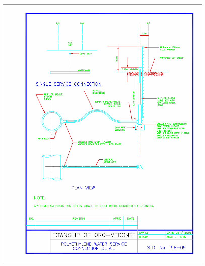


127
3.9 Sanitary Collection Sewers
Prior to the commencement of a design for any sanitary sewage works, the applicant
shall obtain confirmation from the Township that adequate treatment plant capacity is
available for the development proposed.
Sanitary sewers designed and constructed in accordance with the most recent
requirements and specifications of the Township are required to carry domestic,
commercial and industrial sewage from each area of the development under
consideration. Flow is to be by gravity, in general. Pumped systems may be considered
only where other alternatives are not possible and only with the approval of the
Township.
3.9.1 Sanitary Drainage Plans
All tributary areas used for the determination of the design flows shall be shown on a
plan at the scale of 1:1,000. The plan shall indicate the land use, area and population
density or number of units.
Standard sanitary sewer design sheets shall be used to compute the design flow for
each leg of sewer. Each sanitary drainage area on the plan shall show an identification
number along with population and area.
All actual sanitary sewer invert elevations shall be indicated on the As-constructed
drawings. If difference is greater than 150 mm from the design vertical alignment,
affected portions of the sewer shall be redrawn in profile. Any maintenance hole which
differs from proposed horizontal location by more than 1.50 m shall be redrawn in both
plan and profile.
In addition the following shall be indicated on the As-constructed drawings:
pipe size, grade, type, class;
chainage from MH along main to service tees;
dimensions from lot corners and elevations for service laterals.

128
NOTE: If As-constructed grade of sewer differs by more than 1% of the design grade,
the Developer’s Consulting Engineer shall submit revised hydraulic calculations.
3.9.2 Sanitary Drainage System Design
3.9.2.1 Design Flows
The design flow in each length of sewer shall be computed on the standard sanitary
sewer design sheets. For each area entered on the design sheet, the maintenance hole
numbers, the size and grade of the sewers, and the plan and profile drawing reference
number for each section of the sanitary sewer shall also be shown.
Calculations shall be based be the following:
3.9.2.2 Infiltration Rates
A peak design flow of 0.23 L/s/ha shall be used for infiltration. To satisfy self-cleaning
requirements in sanitary sewers, assume dry weather infiltration reduces to zero for
several days during dry months.
3.9.2.3 Residential Sewage Flows
The following formula shall be used to calculate the sewage flow for residential areas:
Q (d) = PqM + IA
86.4
Where;
Q (d) = Peak domestic flow plus extraneous flows, in L/s
P = Design population, in thousands
q = Average daily per capita flow, in L/cap/d
M = Peaking factor
I = Unit of peak extraneous flow, in L/s/ha
A = Gross tributary area, in hectares
An average daily per capita flow of 450 L/c/d shall be used for new development.
The value of peak extraneous flow shall be 0.23 L/s/ha.

129
The peaking factor shall be calculated based on the Harmon formula,
M = 1 + 1 4
4+P0.5
Where:
P = population, in thousands
Maximum M – 4.0
Minimum M – 1.5
The design population shall be derived from the drainage area and expected maximum
population over a design period of 20 years.
For areas where the lands are zoned for specific residential use, but detailed planning
information is not available, the following population densities shall apply for calculation
of sewage flows only.
Type of Housing Units/Hectare
Single Family Residential, 12
Multiple Residential 42
When the number and type of housing units within a proposed development are known,
the calculation of population for the proposed development shall be based on the
following.
Type of Housing Person/Unit
Single Family Dwelling, 2.58
Semi-detached & Duplex 2.58
Townhouse 2.34
Apartment 2.10
Future land use and population shall be based on the approved Official Plan and
Secondary Plans of the area and the County of Simcoe Approved Land Budget for Oro-
Medonte.
130
3.9.2.4 Commercial Sewage Flows
An average design flow of 28 m3/ha/day shall be used for the design of all local sewers,
with a peak factor of 1.60.
A peak design flow of 0.10 L/s/ha shall be used for infiltration.
The area shall be based on the gross lot area.
3.9.2.5 Industrial Sewage Flows
An average day design flow of 36 m3/ha/day for industry shall be used (excludes
infiltration and peaking effects).
The area shall be calculated using the gross area included in the industrial block or
development.
Peak flow and infiltration factors shall be applied as per the latest MOECC Design
Guidelines.
3.9.2.6 Institutional Sewage Flows
A design flow of 28 m3/ha/day shall be used for the design of all local sewers, with a
peak factor of 1.60.
A peak design flow of 0.10 L/s/ha shall be used for infiltration.
The area shall be calculated using the gross area included in the school or institutional
site.
3.2.9.7 Pipe Capacities
Manning’s formula shall be used in determining the capacity of all sanitary sewers. The
capacity of the sewer shall be determined on the basis of the pipe flowing full.
For all types of pipe a roughness coefficient of n = 0.013 shall be used.

131
3.9.2.8 Flow Velocities
Minimum acceptable velocity = 0.6 m/s
Maximum acceptable velocity = 3.0 m/s
The velocity change in a maintenance hole shall not exceed 0.6 m/s.
3.9.2.9 Pipe Grades
The maximum and minimum grades for pipes shall be the grade necessary to meet the
maximum and minimum velocity requirements except that the required grade for the
minimum velocity requirement shall not exceed 2% or the road grade where the road
grade exceeds 2%.
3.9.2.10 Minimum Sizes
The minimum size for an on-street sanitary sewer shall be 200 mm diameter.
3.9.2.11 Depth of Sanitary Sewers
The minimum desirable design grades shall be 0.5% for all local sewers and 1% for the
first upstream leg.
The depth of the sewer shall be measured from the final centreline finished road
elevation to the top of the sanitary sewer.
In all instances, the proposed sanitary sewer shall be installed at a depth sufficient to
also service lands external to the site as determined by the Township.
For residential, commercial and institutional areas the minimum depth shall be 2.8 m.
For industrial areas, the minimum depth shall be 2.15 m.
Sanitary sewers shall be located below basement floor elevations to allow for the
installation of sewer laterals. Generally, the sanitary sewer shall be at least 1.0 m below
the basement floor elevations.
132
3.9.2.12 Location
All sanitary sewers shall be located as shown on the typical Township roadway cross
sections.
In general, this location is along the centreline of the roadway. A minimum horizontal
clearance of 3.0 m is required between the sanitary sewer and watermain.
3.9.2.13 Storm Sewer and Watermain Crossings
A minimum clearance of 0.50 m shall be provided at the point of crossing between the
outside of the pipe barrels of all sewers, services and watermain.
The sanitary sewer connections are required to go under the storm sewer.
3.9.2.14 Limits of Construction
Sewers shall be terminated with a maintenance hole at the upstream subdivision limits
when external drainage areas are considered in the design. The design of the terminal
maintenance holes must allow for the future extension of the sewer.
3.9.2.15 Sewer Alignment
Sanitary sewers shall be laid in a straight line between maintenance holes unless radius
pipe has been designed. Joint burial (common trenching) with storm sewers may be
considered when supported by the recommendations of a soils report prepared by the
Developer’s Geotechnical Engineering Consultant.
3.9.2.16 Changes in Pipe Size
No decrease of pipe size from a larger size upstream to a smaller size downstream
shall be allowed regardless of the increase in grade.

133
3.9.2.17 Pipe Bedding
The class of pipe and the type of bedding shall be designed to suit loading and
proposed construction conditions. Details are illustrated in the OPSD standard Bedding
and Backfill details. In general, Type B bedding and cover (compacted Granular A
bedding and cover over the sewer) shall be used for rigid pipe sewers.
Embedment for flexible pipe shall be homogeneous Granular A material in accordance
with OPSD requirements.
The width of trench at the top of the pipe must be carefully controlled to ensure that the
maximum trench width is not exceeded unless additional bedding or higher strength
pipe is used.
Alternate granular materials for pipe bedding may be specified, subject to the approval
of the Township, however clear stone bedding is generally not permitted. In areas
where it is difficult to control the infiltration of ground water into the sewer trenches clear
stone bedding may be considered provided it is completely wrapped in a suitable
geotextile, selected and installed in accordance with the manufacturer’s requirement.
Where poor soil conditions and high ground water levels are present, the Developer’s
Consulting Engineer shall prepare special designs for the Township’s approval.
3.9.2.18 Materials
For single family and semi-detached units, multiple family, and other residential blocks,
the service connections shall be PVC.
All bends on sanitary service connections shall be long radius, sweep bends.
Sanitary sewers shall be constructed of reinforced concrete pipe, Polyvinyl Chloride
(PVC) pipe or polyethylene.
The type and classification of all sanitary sewer pipe shall be clearly indicated on all
profile drawings for each sewer length.

134
Reinforced concrete pipe shall be used for sewers 600 mm diameter or larger. PVC
pipe may only be used for sanitary sewers up to and including 600 mm in diameter.
Reinforced Concrete Pipe shall be steel reinforced and conform to OPSS 1820.
Polyvinyl Chloride Pipe (PVC) shall conform to OPSS 1841.
Dimension ratio (DR) of PVC sewer pipe shall not exceed 35.
Polyethylene pipe shall conform to OPSS 1840.
For sewer applications requiring pressure pipe, pipe design should reference the latest
MOECC guidelines.
3.9.2.19 Maintenance Hole Requirements
Maintenance holes to be precast concrete and shall be designed and constructed in
accordance with the most recent OPSS and OPSD. Where the standard drawings are
not applicable, the maintenance holes shall be individually designed and detailed.
3.9.2.20 Location and Spacing
Maintenance holes shall be located at each change in alignment, grade or pipe material,
at all pipe junctions and at intervals along the pipe to permit entry for maintenance to
the sewer.
Maximum spacing of maintenance holes shall be 110 m for sewers 900 mm or less in
diameter and 180 m for sewers 975 mm or greater in diameter.
3.9.2.21 Maintenance Hole Details
All maintenance holes to be minimum 1500 mm diameter.
All maintenance hole chamber openings shall be located on the side of the
maintenance hole parallel to the flow for straight run maintenance hole, or on the
upstream side of the maintenance hole at all junctions.
The maintenance holes shall be centered on the sanitary sewer main.
The maximum change in the direction of flow in any sanitary sewer maintenance
hole shall be 90 degrees. Flow direction changes at acute interior angles shall not be
permitted.

135
A maximum invert drop of 0.25 m within the maintenance hole shall be allowed only
if the design of the sewer cannot be modified to reduce the drop or modified to
accommodate a drop structure.
If the design of the sewer system is such that the difference in elevation between the
maintenance hole inlet and outlet exceeds 0.6 m, then a drop structure shall be
required.
Whenever feasible, sewer systems should be designed to avoid the use of drop
structures.
When pipe size does not change through a maintenance hole and the upstream flow
velocity does not exceed 1.5 m/s, the following minimum invert drops across the
maintenance hole shall be made to compensate for hydraulic losses:
Change in Direction Minimum Drop (mm)
Straight run 30
≤ 45° 50
> 45° ≤ 90° 80
When the upstream flow velocity exceeds 1.5 m/s, the drop required through a
maintenance hole shall be calculated using the standard calculation sheet, Hydraulic
Calculations for Maintenance Holes” found in the latest MOECC Design Guidelines.
For all junction and transition maintenance holes, the drop required shall be
calculated using the standard calculation sheet “Hydraulic Calculations for
Maintenance Holes” found in the latest MOECC Design Guidelines.
The obvert(s) on the upstream side of a maintenance hole shall in no case be lower
than the obvert(s) on the downstream side of the maintenance hole.
All maintenance holes shall be benched as detailed on the Standard Drawings.
All maintenance holes shall have frost straps in accordance with OPSD 701.100.
When any dimension of a maintenance hole exceeds those on the Standard
Drawings, the maintenance hole must be individually designed and detailed.
Safety gratings shall be required in all maintenance holes greater than 5.0 m in
depth.

136
Safety grates shall not be more than 5.0 m apart and shall be constructed in
accordance with the Standard Drawings. Whenever practical, a safety grating shall
be located 0.5 m above the drop structure inlet pipe.
3.9.2.22 Frame and Grate
All maintenance holes located within the travelled portion of a roadway shall have the
rim elevation initially set flush with the surface of the base course asphalt. The
concreting and setting of the frame and cover shall be completed in accordance with the
applicable OPSS/OPSD. A minimum of two modular rings and a maximum of 300 mm
of modular rings shall be permitted on maintenance holes in new subdivisions. Use
Denso Re-instatement Tape Seam Seal Mastic or equivalent. No concrete shall extend
over the edge of the maintenance hole.
Prior to the placement of the final lift of asphalt, maintenance hole frames shall be reset
to final elevation.
Where maintenance holes are located in areas to be flooded by the major design storm,
maintenance hole covers shall be water tight and the maintenance hole is to be suitably
vented.
All other maintenance hole covers shall be as per OPSD 401.010 with Type A closed
cover labelled “Sanitary”.
3.9.2.23 Service Connections
All sanitary sewer service connections for single and semi-detached dwellings and
townhouse units shall be individual services.
Location
The proposed locations for the sanitary sewer service connections shall be shown on
the plan and profile drawings and shall be in accordance with the locations specified on
the Standard Drawings.

137
Sanitary connections shall be in accordance with the following Standards:
OPSD 1006.010 Sewer Service Connection for Rigid Pipe;
OPSD 1006.020 Sewer Service Connection for Flexible Pipe.
Residential connections shall terminate at the center of the property line with a test
fitting, plug suitably braced to withstand test pressures and 89 mm x 38 mm marker
placed from the invert of the connection to 600 mm above grade painted green. All
service connections to be equipped with a clean out to the surface as illustrated in the
Standard Detail Drawings.
3.9.2.24 Connection to Main
The connection to the main sewer shall be made with an approved manufactured tee.
Approved saddles shall only be used for connecting to existing sewer mains.
No service connection of a size greater than half the diameter of the main sewer shall
be cut into the main sewer. A maintenance hole shall be installed on the main sewer at
the intersection of a service connection, which has a size greater than half the diameter
of the main sewer except where a 150 mm service connection shall be permitted to
connect to a 200 mm or 250 mm main sewer providing an approved manufactured tee
is installed and provided that the invert of the service connection is above the spring line
of the main sewer.
3.9.2.25 Size
Sanitary connections are to be sized as follows:
Single family residential
single 125 mm diameter (min.) PVC SDR 28
Joints; Bell and Spigot with rubber gasket. Watertight test fitting, plugged and
braced at property line.
PVC pipe to be green in colour.

138
Service Connection to all block developments
An inspection maintenance hole shall be required on private property 1.50 m
from property line to centre of rim.
Industrial / Commercial / Institutional and Apartment industrial Blocks shall be
designed in accordance with Section 3.3.
have a minimum water service size of 150 mm diameter
3.9.2.26 Depth
The depth of the service connections for single-family units and semi-detached units at
the property line, measured from the final centreline road elevation shall be a minimum
of 2.60 m
Risers shall be used when the depth to obvert of the sewer main exceeds 4.50 m. The
riser connection shall not exceed 3.0 m in depth.
3.9.2.27 Grade
The minimum and maximum grades for sanitary sewer service connections shall be as
follows:
Size of Connection
(mm)
Minimum Grade (%) Maximum Grade (%)
125 2.0 8.0
150 1.0 6.0
200 0.5 6.0
3.9.2.28 Joints and Bedding
Joints and bedding for connections are to be equivalent to joints and bedding as
specified for sanitary sewer pipe.

139
3.9.3 Testing and Acceptance
All testing shall be carried out from maintenance hole to maintenance hole including
house service connections as work progresses. An infiltration or exfiltration test as per
OPSS 410 shall be completed on all sewers 1200 mm in diameter and smaller. The
Township shall determine which test is to be undertaken. Low pressure air testing may
be considered.
3.9.3.1 Deflection Test
A deflection test shall be performed on all sewers constructed using PVC pipe material.
Deformation gauge (Pig) test as per OPSS is required on all pipe works prior to
Substantial Performance, but a minimum 30 days after installation.
3.9.3.2 Video Record
A Closed Circuit Tele-Vision (CCTV) inspection (including flushing) as per OPSS 409
shall be conducted upon satisfactory completion of all other testing, prior to the
Township’s recommendation for issuance of “Substantial Completion” and prior to the
placement of surface course asphalt. A CCTV inspection (including flushing) shall also
be required prior to the issuance of “Final Acceptance” if 18 months have lapsed since
the placement of surface course asphalt.
A permanent record in DVD form shall be supplied to the Township, illustrating a
continuous record of the sewer installations, service connections, maintenance hole,
etc. A report identifying any unusual or sub-standard condition(s) shall also be
submitted to the Township.

140
THIS PAGE INTENTIONALLY LEFT BLANK


141
3.10 Plan and Profile Drawings
Plan and Profile drawings are required for all Township roadways, blocks and
easements where services are proposed within the development, for all outfalls beyond
the development to the permanent outlet, for all boundary roadways abutting the
development and for other areas where utilities are being installed below grade. Plan
and Profile drawings are to be drawn to a maximum horizontal scale of 1:500 and a
maximum vertical scale of 1:50 and are to include the following:
complete legend
all existing or proposed services, utilities and abutting properties are to be shown in
light or background weight lines
all services to be constructed are to be shown in solid lines
the profile portion of the drawing shall be a vertical projection of the plan portion
whenever possible
all road allowances, lots, blocks, easements and reserves are to be shown and are
to be identified in the same manner as on the Registered Plan
pavement / road base designs for the particular roadway are to be indicated on all
plan and profile drawings
all curb and gutter and sidewalks shall be shown and dimensioned on the plan
portion of the drawing
where multiple drawings are required for one road, match lines must be used and
tied in to the nearest full station and such station shall be indicated with no overlap
or duplication of information
where intersecting roads or easements are shown on a plan-profile, only the
diameter of the pipe and direction of flow of the intersecting sewers shall be shown.
This also applies to easements for which a separate plan and profile has been
drawn.
on profile portion of drawings the type of sewer, diameter, length and grade shall be
shown
on profile portion of drawings the watermain diameter and length, shall be shown

142
only the type, direction of flow and diameter of pipe shall be shown in the plan
portion;
all maintenance holes shall be shown on the plan and on the profile portions of the
drawing and be identified by chainage and I.D. number and shall also be referred to
the applicable Standard Drawing or to a special detail on the profile portion of the
drawing. All invert elevations shall be shown on the profile with each having
reference to the north arrow
all sewer maintenance holes which have safety platforms are to be noted
all drop connections are to be noted and referred to the Standard Drawing
all catch basins and catch basin connections shall be shown. Catch basins are to
be numbered for easy reference. All rim and invert elevations for rear lot catch
basins are to be shown
all watermain, hydrants, valves, bends and fittings, etc. shall be shown, described
and dimensioned on the plan portion of the drawing. In addition, the watermain shall
be plotted to true scale size on the profile portion of the drawing, complete with
details on the depth of cover
the location of all storm, water and sanitary service connections shall be shown on
the plan portion of the drawing using different symbols for each service. These
services need only be dimensioned when the location differs from the standard
location as shown on the Township Standard Drawings. The connections to all
blocks in the development shall be fully described and dimensioned (size, length,
grade, invert elevations, materials, class of pipe, bedding, etc.)
the existing and proposed centreline road grades shall be shown every 20 m with
stations shown measured in metres (i.e. STA 0+000, STA 0+020) at even 10 m
intervals to be indicated in vertical curves
beginning and end of curve stations, intersections and end stations shall also be
shown to three decimal points
the original ground at centreline and the proposed centreline road profile shall be
plotted on the profile. The proposed centreline road profile shall be fully described
(length, grade, P.I. elevations, vertical curve data, high point chainages, low point
chainages, etc.)

143
details of the gutter grades around all 90 degree crescents, intersections and cul-de-
sac shall be provided on the plan portion of the drawing as a separate detail at a
scale of 1:100
special notes necessary to detail construction procedures or requirements are to be
shown
chainage for the centreline of construction are to be shown on the profile portion of
the drawing. The P.V.I., B.H.C., E.H.C., B.V.C. and E.V.C. chainages are to be
noted;
the basement elevation of all existing dwellings on roads where sewers are to be
constructed shall be noted on the profile
all existing services, utilities and features shall be shown on the plan portion. Those
services and utilities below grade that are critical to the new construction shall also
be shown in the profile. Test holes may be required to determine actual elevation of
these services and utilities
profiles of roadways shall be produced sufficiently beyond the limits of the proposed
roads, to confirm the feasibility of possible future extensions
the location of all luminaire poles shall be clearly shown on the plan portion
the proposed location and type of all road names and traffic control signs shall be
shown on the plan portion
proposed locations and types of all trees to be shown on the plan portion
where possibility of conflict with other services exist, connections are to be plotted
on the profile or a crossings chart included
the detail information from all borehole logs is be plotted on the profile drawings and
located on the plan

144
THIS PAGE INTENTIONALLY LEFT BLANK
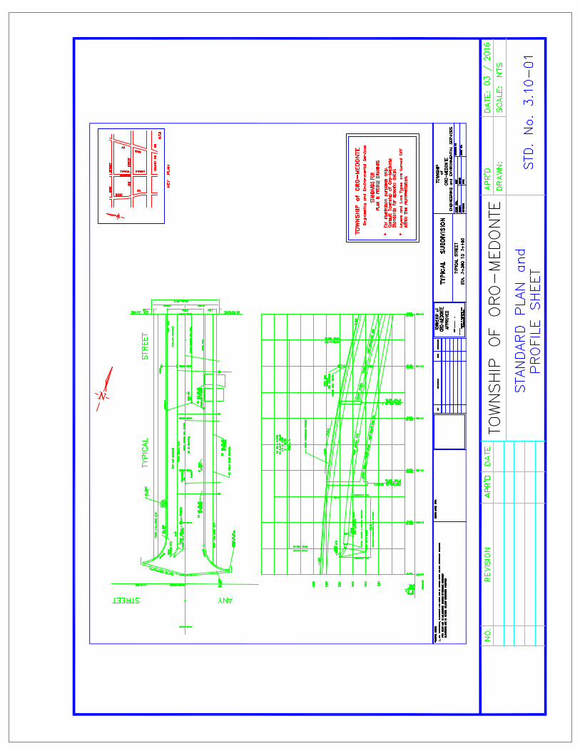

145
3.11 Utility Coordination, Composite Utility Plan and Electrical Services Design
3.11.1 Utility Coordination
The appropriate utility company or their approved contractor shall install the services for
Telecommunications, Hydro, Gas, and Cable TV.
The Developer must bear the cost of all surcharges for underground installation made
and must grant all necessary easements for their services. Where possible, utilities
shall be kept 1.0m behind curbs and vertical and horizontal alignment should conform to
plan and inspection prior to backfill.
Compaction of backfill for utility trenches shall be 95% Standard Proctor Density within
boulevards and 100% for driveways and under travelled roads.
Utility crossings for new roads shall be placed prior to placement of granular road base
material. Utility crossings for existing roads must be augured or bored under the existing
road structure. Should it not be feasible to auger or bore, utility crossings for existing
roads shall have the asphalt surface saw cut and removed for a width of the trench plus
a minimum of 0.5m out from each side of the trench walls.
No disturbance by road cut shall be allowed on any new road surface within the first
three (3) year period after assumption by the Township.
3.11.1.1 Canada Post
The Developer’s Consulting Engineer must submit and liaison directly to Canada Post
for the locating of their proposed facilities. All proposed locations must be shown on the
Composite Utility Plan. Temporary Post Boxes must be placed in accordance with the
approved final location. All community mailbox facilities must be provided with a paved
single lane lay-by and a streetlight.

146
3.11.2 Composite Utility Plan
The Composite Utility Plan shall be prepared in the same format as the “General Plan of
Services” and show all the same aboveground information as well as the proposed
location of driveways, streetlights, manholes, catchbasins, fire hydrants, valves, Bell
Canada, Hydro, Gas, Cable TV and Canada Post facilities. All locations must be
established and resolved by the Developer’s Consulting Engineer in conjunction with
the Utility companies and in accordance with the locations shown on the typical cross-
section.
3.11.3 Electrical Services Design
It is the Developer’s responsibility to make direct arrangements engage an Electrical
Engineer (Developer’s Electrical Consultant) to design and construct the primary and
secondary electrical distribution system, together with all necessary plans.
Where Site Plan proposals abut County or Provincial roads, lighting level plans with
supporting computer printouts shall be submitted to the respective road authorities for
their approval, if required.
Electrical distribution systems shall generally be designed as buried systems. All
requirements for the design of the electrical distribution and streetlighting system shall
be agreed upon with the Township and the appropriate Electrical Authority.
Plans shall be submitted showing the location of (but not limited to): hydro poles, pole
mounts, pole mounted transformers, underground ducts and wiring, pad-mounted type
transformers, transformer size, duct banks, size of wiring etc.
Electrical distribution systems shall not be constructed over the watermain.


147
3.12 Streetlighting
Streetlights are required for all roadways and most walkways in the Township, and
other locations as directed by the Township. Streetlighting systems are the
responsibility of the Developer to construct and the Developer shall engage an Electrical
Consultant to design the Streetlighting system.
The Streetlighting system designs shall be prepared by the Developer’s Electrical
Consultant and submitted to the Township for approval. The illuminance method as
outlined in the American National Standard Practise for Roadway Lighting
ANSI/IES RP-8-14 (2014) or latest edition is to be used as a guideline.
All streetlighting shall consist of Dark Sky Friendly (Full cut-off) luminaires and fixtures.
Designs must show that fixtures have no up light focus. Fixtures must be designed in
such a way that there is a minimum horizontal and “zero” vertical lighting focus. The
photometrics of fixtures shall be submitted for review with preliminary design
submissions of development plans.
Where photometric analysis determines a more appropriate or alternative wattage or
spacing, consideration may be given to the alternative design provided that illumination
levels do not compromise traffic or pedestrian safety.
The Developer shall arrange with Hydro One for the connection of all lighting systems.
The estimated cost of the total installation must be approved by the Township. The
Developer shall provide easements wherever they are required.
3.12.1 Streetlight Locations
• Where possible, pole locations are to be placed on the projection of side lot lines.
• Where community mail boxes are proposed within a plan of subdivision,
streetlights must be located immediately adjacent to them.
• The maximum allowable spacing between lights shall be 60 m or as approved by
the Township.

148
• Streetlights are to be provided such that there is adequate illumination at all
intersections.
• Streetlights are to be provided at the end of every cul-de-sac.
• No streetlights should be placed within 3.0 m of a transformer.
• Staggered arrangement of luminaire poles is not acceptable.
• On curving roadways, lights are to be placed on outer radii where possible with
spacing to be reduced by 30%.
• Proposed lighting levels adjacent to Provincial and County roads are to be
reviewed and approved by the appropriate road authority.
3.12.2 Light Source, Fixture and Pole
• All luminaries shall comply with all applicable requirements of CSA Standard
C22.2 No. 250 13-12, “Light emitting diode (LED) Equipment for Lighting
Applications.
• All luminaries shall manufactured by CREE Lighting Inc. – XSPA Type
(Wattage as per Approved Streetlighting Designs.)
• Landmark luminaries shall be used on collector and arterial roads.
• Each light shall be controlled by a dusk to dawn photo electric cell.
• For local roads poles for 7.35 m mounting height are to be direct burial type
round concrete Stresscrete #TEC-30-BPR-CSA “Concrete Poles” complete with
2.4 m aluminium tapered elliptical arm, made by Sylvania or equivalent, 100mm
by 175mm hand hole and cover, ground lug at the hand hole and two below
grade wiring apertures as per Township STD. No. 3.12-01.
• Stresscrete or approved equal poles of appropriate height and class, with
tapered single elliptical aluminium arms of appropriate length, are to be used on
collector and arterial roads.
• Streetlights shall be controlled by an electrical panel mounted in a Powco
Pedestal adjacent to a hydro transformer in accordance with Township STD. No.
3.12-01 and 3.12-02. Installation to meet current Ontario Hydro Guidelines.

149
3.12.3 Approval and Construction
Approval of plans for streetlighting must be obtained from the Township. Electrical
Safety Authority (ESA) approval for the installed streetlighting system must be obtained
by the developer. The Developer must guarantee and maintain the lighting until final
acceptance of the development. The Township, upon energization of the streetlighting,
shall pay energy charges.
3.12.4 Decorative Streetlighting
Upon specific request to the Township, decorative streetlighting may be considered on
a case-by-case basis.
Decorative streetlighting is to generally conform to the requirements of Section 3.12
and all sub-sections as previously described, with the following revisions:
• Poles to be Stresscrete Octagonal Class B-Medium Duty Pole, Eclipse Black
(S11) polished concrete finish
• Luminaries to be CYCLONE L.E.D. - , CLE – 17T4 (Black in Colour) All others require Specific Approval(s)
• Arm to be Aluminous 72” Decorative Scroll Arm, black colour
• Power pedestal to be Pedestal Solutions Inc. Part #SLS Short Streetlighting
Pedestal equipped with Square D 12 Breaker 120/240 VAC Single Phase Panel

150
THIS PAGE INTENTIONALLY LEFT BLANK


151
3.13 Signs, Traffic Signals and Pavement Marking
3.13.1 Signs
Prior to construction, an information sign shall be placed at every access point to the
subdivision detailing:
• noting that the subdivision is Unassumed
• the name of the subdivision
• the Developer and phone #
• the General Contractor and phone #
• the Developer’s Consulting Engineer and phone #
• phone numbers for each of these companies shall be posted on this sign.
The following types of signs shall be posted on Township R.O.W.’s:
• Municipal Numbering
• Road Name Signs
• Traffic Control and Advisory Signs
• Municipal Information Signs
All signs so installed shall be done so in accordance with the latest edition of the
Ontario Traffic Control Manual and standard road name signs approved by the
Township of Oro-Medonte.
Unless specifically authorized by the Township, no sign, fingerboard, notice, or
advertisement of any kind shall be posted or deposited on road allowance under the
jurisdiction of the Township.
3.13.1.1 Municipal Address Numbering
The Developer is responsible for obtaining designated Municipal Address Numbering for
each and every lot from the Municipal Office. The designated Municipal Address
Numbering shall be shown on the Overall Lot Grading Plan inside the box designating
the location of the house. The actual location of installation is shown on Township
Standard 3.13-02.

152
3.13.1.2 Road Name Signs
The naming of all newly created roads under jurisdiction of the Township shall meet
with the Township’s approval and shall not be in conflict with any existing road name.
All road names must be submitted to the Township for approval in accordance with the
Township’s Street Naming Policy.
Unless specifically stated otherwise, it is the responsibility of the Developer to supply
and erect road name, regulatory and parking control signs in a location approved by the
Township.
3.13.1.3 Traffic Control and Advisory Signs
All traffic control and advisory signs shall conform to the current revised standards of
the Ontario Traffic Manual.
3.13.1.4 Access / Haul Route Plan / Information Signage – During Construction
The Developer shall indicate the access/haul route to be used by the suppliers,
contractors and other agents during construction. Location of informational/directional
signage, route arrows and road patterns and all other pertinent information that shall be
needed to satisfy the Township that the access/haul routes are limited and maintained
to cause the least amount of disturbance to the adjacent land owners. Information signs
are required at every access point to the subdivision. The Developer is responsible to
maintain the directional/informational signage until final acceptance by the Director of
Engineering and Environmental Services or otherwise directed by the Township.
Upon completion of base course asphalt, the Developer shall place signage at each
point of ingress / egress to the subdivision stating the following:
THIS ROAD UNASSUMED BY THE TOWNSHIP OF ORO-MEDONTE
USE AT OWN RISK
Each sign shall be 450 mm wide by 600 mm high with black letters on white
reflectorized background, mounted on “U’ channel posts, 3.65 metres in height.

153
3.13.1.5 Location
Traffic control and advisory signs shall be located as shown on the Township of Oro-
Medonte Standard Drawings. In cases where the positioning of the signs is not covered
by the standard drawings, the location must be in conformance with the Ontario Traffic
Manual or the Highway Traffic Act Regulations for Ontario.
All signs, with exception of “Parking” signs, shall be mounted approximately at right
angles to the direction of and facing the traffic that they are intended to serve. On
curved alignments the angle of placement should be determined by the course of the
approaching traffic rather than by the roadway edge at the point where the sign is
located. Signs for different purposes should not be placed closer together than 30 m.
Parking signs shall be mounted facing 30 – 45 degrees to the flow of traffic.
3.13.1.6 Erection
All traffic control signs shall be mounted on galvanized steel punch out type or
Uniflange type posts, 3.65 m in length. Channel posts shall be a minimum 14 gauge
thick and a minimum width of 45 mm. The posts shall be pre—punched with a minimum
of 24 holes at 50 mm centres compatible with standard bolthole arrangements for traffic
control signs. Signs shall be individually erected on separate posts.
Traffic control signs must be erected by the Developer at the completion of the base
course asphalt road construction and prior to the issuance of Building Permits. Signs
must be maintained by the Developer until Final Acceptance and Assumption by the
Township.
3.13.2 Traffic Signals
Where it has been determined by a qualified Traffic Engineer that traffic signals are
required; the traffic signals shall be designed on individual site-specific basis and must
conform to Ontario Traffic Manual, Book 12.

154
3.13.3 Pavement Markings
The Developer shall design pavement markings for all roadways over two lanes in width
or as required by the Township. The design shall be in accordance with the Ontario
Traffic Manual, Book 11 and approved by the Township. These pavement markings
shall be installed on both the top coarse of asphalt and the base coarse of asphalt. The
Developer shall be responsible for stop bars on roadways that are up to two lanes in
width. All roadway markings shall be installed in accordance with OPSS 532.


155
3.14 Sidewalks, Walkways, Trailways and Fences
3.14.1 Sidewalks
Sidewalks may be required in subdivision developments and may be also required
where specified by the Director of Engineering and Environmental Services as walkway
links through parkland, and as connective links between cul-de-sacs and other points of
pedestrian movement. Sidewalks shall be constructed in accordance with Township
Standards.
Where the development generates the need, in the opinion of the Director of
Engineering and Environmental Services sidewalks may be required on existing roads
external to the plan or roads where reverse frontage is proposed.
Sidewalks shall be constructed as required within the plan for the proper circulation of
pedestrian traffic and shall be in accordance with the most recent requirements and
specifications of the Township of Oro-Medonte.
The Township requires that all concrete sidewalks be constructed as indicated on the
approved Engineering Drawings, prior to the release of the first conditional or
unconditional Occupancy Certificate in accordance with the Subdivision Agreement and
no later than one (1) year after the completion of base course asphalt.
3.14.1.1 Location
Sidewalks shall be constructed on Township of Oro-Medonte roads as shown on the
Township’s Road Cross-section and streetlight poles should be located on the same
side as the sidewalk. Local roads with an A.A.D.T. of approximately 100 or greater shall
have a minimum sidewalk constructed on one side and Arterial / Collector Roads or
roads with an A.A.D.T. of approximately 1000 or greater shall require sidewalks on both
sides. Sidewalks shall be of Barrier Free Design.

156
Placement of the sidewalk shall generally be in the following priority:
• North and east side of road to take advantage of the sun.
• Minimum driveway crossings.
• Reduced road crossings.
• Inner side of Road Elbows.
• Through the access easements on cul-de-sacs.
• Where practicable, on the same side as the streetlights.
3.14.1.2 Specification
All sidewalks shall be of a Universal Barrier Free design throughout their length and at all
intersections and crossings. The standard width for residential development is 1.5m. The
sidewalk shall be constructed 25mm higher than the finished sod on the downstream side
and flush to the finish sod on the upstream side.
Concrete strength used in sidewalks shall be 30 MPa concrete with 7.0% ± 1.5%, air
entrainment. Concrete sidewalks shall normally be a minimum of 150mm thick, 150mm
thick across residential driveways and 200mm thick across commercial or industrial
driveways. Sidewalks shall comply with OPSD 310.010, 310.020, 310.030, 350.010,
351.010 and OPSS 351 on a 150mm compacted Granular “A” base.
Sidewalks shall not be constructed on organic soils. Sidewalk profile and cross fall shall be
such that it does not interfere with the proposed drainage pattern.
3.14.2 Walkways and Trailways
The Developer may be required to design and construct a trail system or walkways and
linkages to existing trail systems. Walkways shall be required adjacent to parkland, in
general. Walkway easements adjoining parallel roads or acting as service access shall
be fenced, gated, signed and planted according to Township Standards. The provision
of new trails shall support a Township wide trails network.

157
The Township’s trails network shall generally be comprised of the following:
• multi-use urban cycle trails, 3.0 m width (hard surface, multiple user);
• multi-use rural soft surface trails, 3.0 m width (crusher fines, multiple users);
• greenway trails, 2.0 m width (soft surface, 4-season multi-use trails);
• snowmobile trails;
• road-based cycle routes.
Proposed trails should link together local points of interest, all open space amenities,
civic institutions and connect to the regional trails network. To the extent possible the
route should utilize public open spaces, unopened right-of-ways, blocks and easements
away from roadways. In the event trails are located along roadways additional right-of-
way width may be required by the Township.
Trails connecting through settlement areas located within the road right-of-way should
be paved multi-purpose cycle ways.
Trails through sensitive natural features should be designed as soft surface paths and
located to avoid fragile areas.
Entrance points to the trail system should be marked with signage coordinated with the
Township.
The minimum standard for the multi-use urban trail shall be:
• 3.0 m width, of 50 mm HL3 asphalt;
• 200 mm Granular “A” base compacted to 95% SPDD.
3.14.3 Fences
Fences shall be constructed in accordance with the most recent requirements and
specifications of the Township as shown on the standard drawings.
Fences are required:

158
• alongside yard flankage and/or rear yards backing onto roadways unless noise
attenuation barriers are required
• along public walkways In accordance with Township Standards
• as designated by the Director of Engineering and Environmental Services
• noise attenuation fences per approved report
The minimum requirements for residential chain link fence heights is in accordance with
the following:
Adjacent Land Use Fence Height (m)
Parklands/Woodlands 1.2
Public Walkways 1.2 in front of dwellings
1.8 between dwellings and rear yards
Pools as per Township Pool By-law
NOTE: All chain link fences shall be galvanized.
Fencing may be required:
• along alongside yard flankage and/or rear yards the perimeter abutting
agricultural lands
The minimum requirements for agricultural fence heights / types is in accordance with
the following:
Adjacent Land Use Fence Height (m)
Abutting Agricultural Lands 1.5 - 10 strand, galvanized ‘farm fence’ with strand spacing of 0.15m hor. and 0.30 ver.


159
3.15 Easements and Blocks
3.15.1 General Requirements
The Township shall require conveyance of easements or dedication of blocks, without
consideration, free and clear of all liens and encumbrances and shall not be part of
parkland dedication calculations, to the minimum width requirements, or greater as
determined by the Director of Engineering and Environmental Services.
All construction and maintenance shall be done in a safe expedient manner with
restoration to be in keeping with the adjacent land use. Under normal conditions, notice
shall be given to the owner of the land indicating nature and duration of the construction
and/or maintenance.
Unless otherwise stipulated, an easement or block shall be granted to The Corporation
of the Township of Oro-Medonte by a proper legally registered document being
sufficiently prepared and the easement or block being particularly described to allow
registration in the Land Registry Office for the County of Simcoe. In the case of
easement, the document shall define the reasons for extending the grant-of-easement.
3.15.2 Easement Width Requirements
Easements for underground services shall be located on one side of the common lot
line between adjacent lots. The easements shall not be permitted to straddle common
lot lines.
Buildings, including footings or building extensions, shall not be permitted to encroach
over the limits of the Township’s easements.
Subject to specific conditions required by the Township, the width of the easement shall
be 6m or twice the depth of the pipe at its deepest point, whichever is greatest.
The minimum width of permanent easements for lot drainage swales shall be 6.0 m.
Additional easement widths may be required depending on the critical depth of swales
proposed.

160
Rear and side yard swale easements designed to convey external or Township
drainage ARE to be centered over the common lot line between adjacent lots.
3.15.3 Block Conveyances
Block Conveyances may be required for, but not limited to the following reasons:
• Rear and side yard piped storm drainage systems, including catch basins, french
drains, maintenance holes and other appurtenances.
• Storm sewers, watermain and sanitary sewers (other than private connections).
• Where underground services are required beyond the limits of a subdivision or
site plan.
• All overland flow routes, open channels, and defined drainage systems
accommodating a major storm.
• Walkways and bicycle paths.
• Valleys, streams, open channels, watercourses (whether flowing or intermittent),
seepage areas, wetlands, natural bodies of water and floodplain lands identified
by the Township as being environmentally significant requiring protection or
designated as hazard or open space lands.
• Stormwater management facilities, including detention and retention ponds,
water quality control facilities and infiltration facilities which are to be owned and
operated by the Township.
3.15.4 Block Width Requirements
Blocks of land shall be of sufficient dimension to accommodate the proposed facility,
access from a public right-of-way and maintenance requirements.
The minimum width of blocks of land for open drainage channels shall be the width of
top of open channel plus 7.5 m along one side of the channel for maintenance
requirements.

161
Valley lands (crest of slope to crest of slope) may be contained within blocks of land to
be conveyed to the Township, as a condition of development. Blocks of land in this case
shall include 3.0 m platform widths on both sides. Blocks of land shall not be
considered as part of parkland dedication requirements as required by the Planning Act.
3.15.4.1 Storm and Sanitary Sewer Mains
The minimum width of blocks for storm and sanitary sewers shall be in accordance with
the following:
Size of Pipe Depth of Invert Minimum Width of Block
250 to 375 mm 3.0 m maximum 6.0 m
450 to 675 mm 3.0 m maximum 6.0 m
750 to 1500 mm 3.0 m maximum 6.0 m
1650 mm and up 4.0 m maximum 4.0 m plus 3 times O.D. of pipe
Where two pipes are to be located on one block, the minimum width of block shall be
the width of block required for the larger of the two pipes plus 1/2 the width of block for
the smaller pipe, rounded to the next 1.0 m increment. Additional block width may be
required to ensure adequate separation between the two pipes and a minimum
separation of 3.0 metres between the block limit and the nearest pipe.
3.15.4.2 Storm Connections for Rear Yard Catch Basins
The minimum width of blocks for leads to rear yard catch basins shall be 5.0 m for pipe
sizes ranging from 250 mm to 450 mm in diameter. For pipe sizes greater than 450 mm,
the above criteria shall apply. The lead shall be centred on the block.
3.15.4.3 Watermain
The minimum width of blocks for watermain shall be in accordance with the following:
Size of Pipe Depth of Invert Minimum Width of Block
Up to 600 mm 3.7 m maximum 6.0 m
675 mm and up 3.7 m maximum 9.0 m

162
3.15.5 Grading Plans for Blocks
Shall be drawn to a scale of 1 to 500 or larger showing existing contours established
from field elevations.
The grading plans shall indicate but not be limited to the following:
• existing contours
• proposed contours for grading within large blocks and parks
• any other points necessary to give proper picture of the proposed drainage
scheme including tops of catchbasins, bottoms of swales and top and bottom
of retaining walls
• existing contours and elevations within the plan and at a minimum distance
externally far enough to determine the existing drainage pattern. In addition to
the above, grading plans for parks are to indicate existing contours at 0.5m
intervals along with all existing trees, structures, watercourses, etc.
• percent road grades for all roads within the development and the distance of
the particular grade shall also be included.
• overland flow routes.
• easements including dimensions and descriptions
• fencing and retaining walls
• drainage types in accordance with typical details
• cut off swales and catchbasins to intercept interim block drainage and
external drainage
• areas of engineered fill
• proposed driveway entrances, streetlight poles, hydro transformers,
underground utility vaults, CATV and Bell pedestals, fire hydrants and valves.

163
3.16 Landscaping
3.16.1 General Requirements
The developer is required to prepare a Landscape Plan, prepared by a qualified
Landscape Architect, to be approved by the Township on a site by site basis.
Due to varying Lot Configurations, the planting design must address the many
variations in lot configurations. The required spacing of trees and minimum setbacks
allows that most lots shall have two (2) trees, some may only have one (1) and some
may have none.
In general, at least two trees shall be planted in front of each single family dwelling,
semi-detached unit and townhouse block. A minimum of two (2) trees shall be placed
along the flankage side of each corner lot.
Trees shall be placed so that its mature form shall not conflict with other essential
services and functions.
Because the presence of utilities, community mail boxes and the curb can interfere with
the preferred placement of street trees, the street tree planting scheme must be flexible
enough to accommodate on-site adjustments.
Detailed Cost Estimates shall be required for all approved Landscape Plans. This
estimate shall be used for security purposes. All streetscape plans shall be consistent
with the Township of Oro-Medonte Development Engineering Policies, Process and
Design Standards and shall require Township approval before implementation of the
plans.
3.16.2 Tree Planting Requirements
Once driveways, utilities and light standards have been installed, the exact location of
street trees shall be determined on site by the Landscape Architect and approved by the
Township prior to planting.

164
The Developer is responsible to plant trees in each lot, 2.0 m from property lines and
abutting the development, in accordance with the specifications established pursuant to
the Subdivision Agreement. Tree locations on Township roads must be confirmed with
the Township.
Minimum clearances for Street Trees (when trees are planted 2.0m from the curb):
• 2m from water hydrants
• 2m from driveways
• 2m from neighbourhood mailboxes
• 2m from fences
• 3m from hydro transformers
• 5m from streetlight poles
• Behind the daylight triangle as per Section 3.10 and / or the Geometric Design for
Ontario Highways
• 18m from face of all warning and regulatory signs
3.16.3 Timing of Construction
All trees are to be placed during either the spring or fall dormant season in unfrozen
soil.
3.16.4 Quality and Source
All boulevard trees shall be #1 quality nursery grown stock, 2.25 m. to 4.0 m. in height
with a minimum trunk diameter of 50 mm. measured at a minimum of 1.0 m. above
ground level. All trees shall be free from physical damage, insects, pests and diseases
and must have at least three quarters of the root system intact.

165
3.16.5 Landscaping Plans
The Landscaping Plans shall be prepared by a qualified Landscape Architect.
The Landscaping Plans shall be drawn and stamped by a Full Member of the Ontario
Association of Landscape Architects. All Landscaping Plans shall be drawn at a
minimum scale of 1:500.
The Developer may request jointly obtaining a Landscape Architect with the Township
(costs are to be borne by the Developer).
The Landscaping Plans shall show all landscaping details as required by the Site Plan
Agreement. A schedule of plant species and sizes is to be identified on the Landscaping
Plans.
All maintenance holes, catch basins, hydrants, valves, streetlights and other servicing
features that appear above grade shall also be shown on the Landscaping Plans.
The Landscape Plans shall include but not limited to the following drawings:
• Existing Natural Features Assessment;
• Tree Survey/Vegetation Analysis;
• Tree Preservation Plan and Details;
• Streetscape and Buffer Planting Plans and Details;
• Detailed Parkland Development Plans and Details;
• Trails Master Plans and Details;
• Landscape Restoration Plans and Details;
• Stormwater Management Facility Planting Plan;
• Lighting Plans;
• Planting Plans.

166
3.16.6 Streetscape Plan
The Streetscape Plan shall show the following:
• existing trees and natural features to remain;
• building envelopes, driveways and sidewalks;
• walkways, trails and easements;
• required fencing including privacy, acoustic and chain link;
• proposed plantings;
• location of streetlighting;
• location of public utility boxes and easements and hydrants;
• heights of existing and proposed retaining walls, fences etc.
Construction details shall be required for all landscape elements to be implemented as
part of the development.
Any required landscape Restoration Plans and Stormwater Management Facility
Planting Plans shall require Township approval prior to implementation of the plans.
Developers are required to display approved landscape plans at the sales pavilions for
the homebuilders in any new subdivision.
Notes for Streetscape and Naturalization Submission Drawings
The following notes pertaining to layout requirements are to be included on all
streetscape submission drawings:
NOTE 1: Depicted on this plan are the species and the approximate location of street
trees. Once driveways, utilities and light standards have been installed, the exact
location of street trees shall be staked on site by the Landscape Architect and approved
by the Township prior to planting.
NOTE 2: The tree pits and planting beds for all trees and shrubs located within 2.0 m of
underground utilities are to be hand dug.

167
NOTE 3: All plant material must conform to the Canadian Standards for Nursery Stock
and must be guaranteed for a minimum period of 12 months following the Final
Acceptance and Assumption of the subdivision works by the Township.
NOTE 4: All plantings and hard landscape features are to be staked out on site and
approved by the Landscape Architect and Township prior to installation. Any deviations
from the approved landscape plans require Township approval.

168
THIS PAGE INTENTIONALLY LEFT BLANK


169
3.17 Parkland Development
3.17.1 Services
The Developer shall provide to the satisfaction of the Township, a water service
connection and sanitary sewer and storm sewer lateral connections to the street line for
the park, if required by the Township. Metering requirements for water service
connections shall be confirmed with the Township.
Where required by the Township, underground primary or secondary electrical cables
shall be placed from the road allowance to designated locations within parkland.
3.17.2 Grading
The Parklands shall be fine graded in accordance with the approved grading plan with
particular care being taken to avoid damage to those trees or features that are to
remain.
• All graded areas shall be covered with a minimum of 150 mm of screened topsoil
and shall be seeded and fertilized in accordance with the specifications of the
Director of Engineering and Environmental Services.
• All topsoil stripped from parklands shall remain on-site and not removed or sold.
The seed mixture proposed shall be approved by the Township prior to
placement.
• All park blocks less than 0.4 ha. shall be sodded on 150 mm of topsoil.
• All stones and debris shall be removed and disposed of by the Developer prior to
the seeding or sodding of a park.
The Developer shall provide chain link fencing along park boundaries or walkways as
required by the Township. Building materials or equipment cannot be stored on
parkland and parkland shall not be used as a dumpsite. Stripped topsoil shall not be
stockpiled on parkland or other Township blocks.

170
3.17.3 Timing of Construction
All park blocks must be graded and seeded or sodded within one year of the completion
of the base course asphalt road construction in the area adjacent to the park. Seeding
must be carried out during the desirable months for seeding of May or September.
Boulevard grading and sodding on road allowances adjacent to parklands shall be
completed at the same time as the park seeding.
3.17.4 Maintenance
The Developer shall be responsible for the maintenance, watering, fertilizing and
mowing of the parklands to Township Standards until Final Acceptance and
Assumption. Security for landscaping shall be held by the Township for 12 months
following Final Acceptance and Assumption.
3.17.5 Parkland Development Drawings
The Developer shall be responsible to prepare a detailed Park Master Plan for approval
by the Township, for all lands to be dedicated for park purposes. This plan shall show
all existing trees and features that are in conformity with the end use of the park and
that are to remain. All other trees shall be removed by the Developer subject to
Township approval. Prior to preparing park development plans, the Developer shall
meet with Township staff to review Township recreational needs, i.e. soccer pitches,
ball diamonds, etc.
A Master Plan shall be prepared at a scale of 1:500 and form part of the approved
Engineering Drawings, indicating the following, at a minimum:
• existing contours at maximum 0.5 m intervals
• drainage structures and direction of overland drainage
• species and size of existing plant material to remain and be protected
• species and size of plant material to be removed
• proposed underground services, as required
• layout of all proposed recreation facilities

171
• layout of parking lot and spaces (including handicapped parking)
• layout of all trails
• proposed site amenities including benches, bike racks, trash receptacles, signs,
washrooms, playground equipment
• perimeter fencing
• park lighting
• all surface treatments
• all proposed plant materials
The developer may be required to design and construct some or all of the items
identified in the Master Plan.
A Park Development Cost Estimate based on estimated quantities with corresponding
unit prices is required along with the drawing submission.

172
THIS PAGE INTENTIONALLY LEFT BLANK


Hierarchy and Planning Guidelines Parks, Open Space and Leisure Facilities - Township of Oro-Medonte, 2010 This hierarchy is intended to categorize parks, other public and publicly available open spaces and leisure facilities into three distinct levels of provision. The classification system will help to differentiate parks and other open spaces intended to serve close-to-home needs from those intended to attract most of their use from a specific population centre/community, or from across the entire Township and beyond. The size and scale of leisure facilities should align with the three levels of parks/open space in the hierarchy. Township-wide/Regional Parks and Open Space
The scale, size and appeal of the parks/open spaces and facilities in this category are intended to attract most visitors from across the Municipality and beyond. Includes: municipal parks (e.g., Bayview Memorial);
County forests; Provincial lands (parks, the Copeland Forest); wetlands, forests and meadows under the auspices of The Couchiching Conservancy; major trails; future conservation authority lands; utility corridors and other prominent linear open space corridors/parks; heritage sites/museums; outdoor performance venue (potential): golf courses; ski areas; equestrian facilities; and other similar sites. Typically attract day-use activities, but could include a
campground. Generally should incorporate indoor and outdoor
facilities that are high order/major in scale and quality - often clusters of similar facilities such as two or more soccer fields or a twin-pad arena. Can accommodate ancillary facilities such as a food
concession, washrooms, change facilities, a club house. Ensure that playgrounds, sitting/viewing areas and
picnic areas are well shaded. Generally should be large sites, but could also be a
small specialized property or facility (e.g., an historic site or a public docking/boat launch area). Are often resource-based (natural or built heritage) and
therefore not necessarily located based on good access, visibility or proximity to population centres. If not resource-based, the location should be driven by
criteria such as: good vehicular and pedestrian access and visibility, and suitability of the site to support desired development/uses. Sites intended to accommodate lighted/major sports
venues should not directly abut a residential area. Whenever possible, sites should be linked to township-
wide trail systems and natural heritage corridors. Incorporate sufficient on-site parking to support uses.
Community Parks and Open Space
The scale, size and appeal of the parks/open spaces and facilities in this category are intended to attract most visitors from within a settlement area such as Moonstone, Warminster, Craighurst, Sugarbush, Hawkestone or Shanty Bay.
For the most part, this category includes municipal parks (e.g., Ramey, Vasey, Sweetwater, Line 4, Danny McHugh, Shanty Bay, Craighurst), community halls, and secondary schools (potential).
Sometimes community-scale sites are combined into a jointly planned and developed park-school campus with shared indoor and outdoor facilities.
Generally may incorporate outdoor and indoor facilities that are intermediate to high order in scale and quality such as: lighted ball diamonds, lighted multiple tennis courts, full size and large mini soccer fields, an arena, a community hall, a picnic area, a major playground, a large floral garden, etc.
If the site is large enough, two or more of one type of facility could be accommodated.
If large enough, a community-scale site may include ancillary facilities such as: washrooms, change facilities, a small food concession, etc.
Community parks should be sited and designed to minimize negative impacts on the adjacent residential area through such measures as planting, fencing, and provision of appropriate parking and access.
Ensure that playgrounds, sitting/viewing areas and picnic areas are well shaded.
Although most sites should be predominantly or entirely >table land= to support the focus on >active= recreation facilities, some sites (and parts of sites) can incorporate wooded areas, watercourses and sloped lands, especially suitable for nature appreciation and tobogganing, and to provide visual and topographic relief.
Whenever possible, sites should be linked to the local, community and township-wide trail systems and natural heritage corridors.
Sites should be accessible to the community with active parks located on or near very main transportation routes.
All sites should be visible, ideally with at least 25% of the perimeter fronting onto a street, and where possible, a major roadway (particularly so if an >active= park).
Minimize the use of fencing around the perimeter of the site.
Sports facilities (especially lighted) should not abut residences.
Generally, this category of park should be a minimum of 10 acres (4 hectares) in size.
Neighbourhood/Local Parks and Open Space
The scale, size and appeal of the parks/open spaces and facilities in this category are intended to attract mostly visitors from nearby residences (within a five to ten minute walk), predominantly for less organized, lower scale leisure activities.
Neighbourhood children should not have to cross a busy street to access the closest neighbourhood park.
For the most part, this open space category includes municipal parks (e.g., Ravines of Medonte, Shelswell, Barrillia, Railside, Price, Emily, Lloyd W. Scott,) and elementary schools. Church sites with turfed, usable open space should be included in this category. Also includes neighbourhood-scale open space linkages and walkways.
Where possible and desirable, combine parks and schools into a jointly planned and developed park-school campus with shared indoor and outdoor facilities and no fencing between jurisdictions. It is appropriate to also incorporate a church with a usable and accessible >yard= into an open space campus (with or without a school).
Generally, Neighbourhood parks should incorporate outdoor facilities that are junior to intermediate in scale and quality such as: a junior ball diamond, a small mini or large mini soccer field, playground(s), a multi-purpose sport pad, a small picnic area; walking path(s), etc. Due to usual location within a residential area, recreational facilities should not be lighted.
Neighbourhood parks should not accommodate indoor facilities.
Neighbourhood parks should be sited and designed to minimize negative impacts on the adjacent residential area through such measures as planting, fencing, and provision of appropriate access.
Ensure that playgrounds, sitting areas and picnic areas are well shaded.
Whenever possible, sites should be linked into the local, community and township-wide trail systems and natural heritage corridors.
Ensure that a minimum of 25% of the perimeter of the site fronts onto a street, and most of the site is visible from the street(s).
Minimize the use of fencing along the frontage of the site.
Although natural heritage features are desirable, most of the site should be table land quality.
Most Neighbourhood parks should range in size from 3 to 8 acres (1. 2 to 3.25 hectares). Occasionally, it is appropriate to create a smaller parkette to augment a park-deficient area, or to meet a specific need such as providing a specialized site for a children’s= play area, a sitting area or a local amenity/accent/signage area. However, even parkettes should not usually be less than 0.5 acres (0.2 hectares) in size.

173
3.18 Standard Detail Drawings and General Notes
The Township of Oro-Medonte Standard Drawings and General Notes shall be utilized
whenever applicable.
The use of the latest revision of the Ontario Provincial Standard Drawings may be
utilized as specified in this document or when approved by the Township.
These drawings shall be reproduced as part of the engineering drawings for the
development and must be referred to by number on the affected plan and profile
drawings.
The Developer’s Consulting Engineer shall be responsible to check the suitability of the
details provided on these Standard Detail Drawings and General Notes for the
application proposed.
Individual details shall be provided by the Developer’s Consulting Engineer for all
special features not covered by the Township of Oro-Medonte Standard Drawings.
These special details shall be drawn on standard sized sheets and shall be included as
part of the engineering drawings.
The minimum scale to be used for special maintenance holes or sewer details shall be
1:25.

174
THIS PAGE INTENTIONALLY LEFT BLANK


175
3.19 As-Constructed Drawings
The As-Constructed drawings constitute the original engineering drawings that have
been amended to incorporate the construction changes and variances in order to
provide accurate information on the works as installed in the development.
The As-Constructed Drawings shall be submitted, prior to the final acceptance of the
subdivision, by the Township. The Developer’s Consulting Engineer shall include in the
As-Constructed set, the complete set of original drawings for the development and
supply them to the Director of Engineering and Environmental Services. In addition, a
complete set of Mylar reproductions (minimum 0.04mm thickness, reverse reading,
matte both sides, black line) shall be prepared from the As-Constructed originals and
supplied to the Director of Engineering and Environmental Services.
These drawings shall show the location both horizontally and vertically of everything,
which is on, and under the lands to be accepted by the Township. These drawings shall
be sealed and signed by a Registered Professional Engineer and stamped As-
Constructed and dated. The Township may perform spot checks of elevations and
locations. If the Township finds major differences, the As-Constructed drawings shall be
returned to the Developer’s Consulting Engineer to be corrected.
NOTE: The As Constructed submission shall include a list of substantial grade,
invert and materials changes for ease of review.
3.19.1 As-Constructed Field Survey
The As-Constructed revisions shall be based upon a final survey of all the subdivision
services and the Developer’s Consulting Engineer’s construction records. The final
survey of the subdivision services shall include a field check of the following items:
• Location and invert elevations of all sewer maintenance holes.
• Distances between all sewer maintenance holes.
• Location of all roadway catch basins.
• Location, rim and invert elevations for all rear yard and lot catch basins.

176
• Location of all sidewalks and curbs.
• Location and ties to all valve boxes and valve chambers.
• Location of all hydrants.
• Location to all special watermain appurtenances (i.e., blow offs, etc.)
• Road centreline elevations.
• Site benchmarks.
• Location of all service connections to all lots and blocks and location of
connection from nearest downstream maintenance hole (i.e. 0 +023).
• Storm and Sanitary Sewer pipe sizes and percentage grades.
• Location of all fencing constructed as part of the subdivision services.
• Streetscape landscaping / boulevard / naturalization plantings.
• Parkland Development Plan.
Locations of the applicable street furniture described above shall also include swing ties
to three fixed reference points and dimensioned on the As-Constructed drawings.
3.19.2 Drawing Revisions
The original drawings shall be revised to incorporate all changes and variances found
during the field survey and to provide the ties and additional information to readily locate
all underground services.
All sewer and road grades are to be recalculated to two decimal places.
All Street line invert elevations of storm and sanitary house connections to each block
shall be noted on the drawing.
All road names, lot numbering and block identification shall be checked against the
Registered Plan and corrected if required.
The As-Constructed revision note shall be placed on all drawings in the revision block.
The title sheet of the Engineering Drawings shall be clearly marked with As-
Constructed.

177
3.19.3 Submissions
Upon completion of all construction work and the As-Constructed revisions, the original
drawings shall be submitted to the Township for their permanent records.
The submission of the As-constructed drawings and digital format to the Township shall
be completed before Final Acceptance and Assumption of the subdivision shall be
granted.
The Developer’s Consulting Engineer shall provide a written declaration to the
Township stating that all subdivision works have been constructed in accordance with
the terms of the Subdivision Agreement, approved Engineering Drawings and the
Township’s Development Engineering Policies, Process and Design Standards, prior to
Final Acceptance and Assumption being granted.
Drawings supplied in a digital format in addition to the standard hard copy shall conform
to the most recent AutoCAD requirements Township Standards.
3.19.4 Tolerances
A maximum vertical plotting tolerance of 0.2 m on the 1:50 vertical profile portion of the
drawings and a maximum horizontal plotting tolerance of 1 metre on the 1:500 scale
drawing shall be considered acceptable without replotting.
All sewer lengths are to be shown to the nearest 0.5 m.
The information shown on the As-Constructed drawings may be checked by the
Township at any time up to two years after final acceptance of the subdivision and if
discrepancies are found between the information shown on the drawings and the field
conditions, then the drawings shall be returned to the Developer’s Consulting Engineer
for rechecking and further revision.
The Developer’s Consulting Engineer shall be required to explain in writing any major
difference between the design and the As-Constructed data and to provide verification
that alteration does not adversely affect the design of the subdivision services.

178
3.19.4.1 Storm Sewers
All actual storm system invert elevations shall be indicated on the As-Constructed
drawings. If the difference is greater than 150 mm from the design vertical alignment,
affected portions of the sewer or overland drainage route shall be redrawn in profile.
Any maintenance hole which differs from the proposed horizontal location by more than
1.50 m shall be redrawn in both plan and profile.
In addition the following shall be indicated on the "as-constructed" drawings:
• pipe/culvert size, grade, type, class;
• chainage from MH along main to service tees.
NOTE: If As-Constructed grade of sewer differs by more than 1% of the design grade,
the Developer’s Consulting Engineer shall submit revised hydraulic calculations.
3.19.4.2 Sanitary Sewers
All actual sanitary sewer invert elevations shall be indicated on the As-Constructed
drawings. If difference is greater than 150 mm from the design vertical alignment,
affected portions of the sewer shall be redrawn in profile. Any maintenance hole which
differs from proposed horizontal location by more than 1.50 m shall be redrawn in both
plan and profile.
In addition the following shall be indicated on the As-Constructed drawings:
• pipe size, grade, type, class;
• chainage from MH along main to service tees;
• dimensions from lot corners and elevations for service laterals.
NOTE: If as-constructed grade of sewer differs by more than 1% of the design grade,
the Developer’s Consulting Engineer shall submit revised hydraulic calculations.

179
3.19.4.3 Watermain
All actual watermain obvert elevations at 30 m intervals shall be indicated on the
As-Constructed drawings. If the difference is greater than 150 mm from design vertical
alignment, affected portions of the watermain shall be redrawn in profile. If horizontal
alignment changes exceed 1.0 m the affected portions of the watermain shall be
redrawn in plan.
In addition the following shall be indicated on the As-Constructed drawings:
• pipe size, type, class
• swing ties to all main appurtenances (valves, bends, tees, etc.)
• chainage from appurtenance along main to main stops
• swing ties from lot corners to the curb stop valve box and the invert elevation of
each curb stop
3.19.4.4 Roadways
All actual roadway centre line elevations, at a maximum 20 m interval, shall be
indicated on the As-Constructed drawings. Gutter elevations shall be indicated for cul-
de-sacs and intersections to show drainage into storm system. If horizontal road
alignment changes more than 1.0 m or vertical geometry changes greater than 150 mm
the plan and/or profile shall be redrawn as appropriate.
In addition the following shall be indicated on the As-Constructed drawings:
• driveways, lay-bys, curb depressions
• road signage
• lane marking and stop bar locations

180
THIS PAGE INTENTIONALLY LEFT BLANK

181
3.20 Residential Lot Grading
3.20.1 General Requirements
The design and completion of lot grading is of primary concern to the municipality, and
the following Township Standards shall apply to all residential development in the
Township of Oro-Medonte.
The Lot Grading Standards set-out provide sites that are suitable for the erection of
residential buildings and to provide satisfactory and environmentally sustainable
drainage of lands within the development and to ensure that lot drainage shall not
adversely affect adjacent properties.
Variances from these criteria may be permitted where the lot grading complies with the
overall design and a reasonable balance is achieved between the provision of relatively
flat amenity areas, effective drainage, the preservation of trees and reducing the
environmental impact of stormwater runoff.
The grading of all lots and blocks in new developments shall be carefully monitored by
the Developer’s Consulting Engineer in order to provide sites that are suitable for the
erection of buildings and to provide satisfactory drainage from all lands within the
development. In this regard, the design of the grading for all developments shall be of
primary concern to the Township and the following criteria shall be used in the
preparation of all lot grading plans for new development in the Township.
All lot drainage shall be designed to conform to the Stormwater Management Report,
overall Lot Grading Plan for the subdivision and Township Standards. The Developer
shall be responsible for performing the grading of lots to the satisfaction of the
Township.

182
3.20.2 Lot Grading Design
• The direction of storm water flow in swales shall be indicated with an arrow and
percentage grades.
• Elevations are to be in relation to geodetic benchmarks or a suitable approved
alternative.
• All easements or rights-of-way are to be indicated on plan.
• Any water course running through or abutting the proposed development
including the identification of the regional storm water levels shall be shown.
• All lots identified with engineered fill shall have a notation indicating Engineered
Fill on the proposed lot grading plan.
• Lot Grading plans shall be stamped by the Developer’s Consulting Engineer to
confirm conformance with these criteria and the overall subdivision lot grading
control plans.
• Lot Grading plans shall be designed in such a way so as to preserve existing trees
wherever possible.
• The front yards of all lots shall be graded to drain towards the road.
• Rear to front lot grading is preferred and a maximum of three rear lots shall outlet
between any two lots.
• All boulevard areas shall be graded with a constant slope from the curb to the
road limit (minimum slope to be 2%, maximum slope to be 5%) and all water
boxes, maintenance hole covers, and valve boxes, etc. shall be set flush with the
finished sod surface.
• Driveways shall not be used as outlets for swales, downspouts or sump
discharges.
• All rear yard drainage shall be directed away from the houses in defined swales
which outlet at the curb, sidewalk or a rear yard catch basin.
• Overland flow routes must be provided for all rear yard catch basins which shall
protect all structures in the event of catch basin blockage or a major storm event.

183
• Drainage within the proposed development limit is to be provided internally. Any
proposed drainage over abutting / adjacent lands shall only be permitted in with
express written agreement with the adjacent property owner(s) and is to be
included as part of the subdivision agreement and legally registered.
• The grading along the limit of the proposed development shall be carefully
controlled to avoid disturbance to the adjoining areas. In general, lot drainage
should be directed away from top of banks or valley slopes.
• The lot grading design shall include provisions for drainage conditions on
adjacent property that can be best resolved by permitting drainage through the
proposed development. Express written agreement allowing for the drainage
provision is to be included as part of the subdivision agreement and legally
registered.
• All lot surfaces shall be constructed to a Minimum grade of 2.0%.
• A minimum of 6 metres adjacent to the rear of the house shall be graded at 2% -
7% slope.
• All lot surfaces shall be constructed to a maximum average lot grade of 12%
(calculated from the difference in lot elevations between the rear wall of the
house and property line - embankments included).
• Maximum slope between all terraces and embankments shall be 3:1 when the
vertical difference does not exceed 1 metre and 4:1 when the vertical differences
exceed 1 metre. Between successive terraces, an intermediate level area of at
least 1.50 metres in width must be provided.
• The maximum flow allowable to any side yard swale shall be that from the
equivalent of three lots or 0.5 hectares, whichever is the lesser.
• The maximum area contributing to a rear yard swale that may be discharged
directly onto a road allowance shall be the equivalent of three rear yards or 0.50
hectares, whichever is the lesser.
Swales providing internal drainage from each lot shall have:
• Minimum slope of 2.0%.
• Minimum depth of a swale shall be 150 mm. @ 3:1

184
• Maximum depth for a side yard and mid-yard swale shall be 450 mm. @ 4:1
• Maximum depth for a rear yard swale shall be 750 mm. @ 5:1
• The Maximum side slope on any swale shall be 3:1.
• Mid-yard Cut-Off Swales (typ. Rear to Front draining lots) shall be sized and
located such as to capture and redirect flow away from residential structures.
• All drainage swales shall be located on lot lines unless the adjacent property is
not undergoing development. In such cases drainage swales shall be located
entirely within the lot being developed.
• Each lot shall have at least one side yard with a maximum slope of 2% for 1.5 m
continuous width from front to rear yard.
• The % grade around houses shall be a minimum of 2% away from houses from a
point 150 mm below top of foundation wall or as required by the Ontario Building
Code (OBC).
• Rear yard catch basins shall be eliminated wherever possible. When approved,
rear yard catch basins and outlet pipes shall be located such that the outlet and
the catch basin are located entirely on the same lot. In general, rear yard catch
basins shall be located 2.0 metres from the lot lines.
3.20.2.1 Driveways
• Houses shall be sited and driveways located to maximize the amount of off-street
parking available to the residence.
• Wherever possible, the driveways should be on the higher side of the lot.
• Driveways shall be set back a minimum of 1.0 m from any tree or above ground
Utility device (hydrants, hydro vaults, light standards, etc.).
• The maximum grade for driveways shall be 7% and the minimum grade shall
depend upon the nature of the surface and not be less than 2%. Where
sidewalks exist or are proposed, driveway grades are to be compatible with
approved sidewalk grades.
• Driveway locations shall not extend beyond lot line projections within the right-of-
way.

185
• Curb Stops and other valves or hardware shall not be located within the
driveway.
• Driveways are not permitted as outlets for drainage swales, downspouts or sump
pump discharge.
• Driveway locations shall be in accordance with the approved Engineering
Drawings
3.20.2.2 Sodding
The subdivision shall be sodded according to the following:
• all swales, ditches, drainage easements, and slopes 10% or greater shall be
sodded using 100 mm screened top soil and No. 1 nursery sod;
• all residential lots shall have a minimum of 100 mm screened top soil and sod,
rear and front;
• where the combined side yard between buildings is less than 3.0 m combined or
1.5 m on any one side, the surface treatment shall be 75 mm of clear stone over
a vegetation suppressing geotextile.
3.20.2.3 Retaining Walls
Retaining walls shall be constructed according to the following:
• where retaining walls are required they shall be constructed on the higher lot
such that the wall and tie-back do not cross property lines
• retaining wall design and construction shall be certified by the Engineer, in
accordance with OBC requirements
• retaining walls shall be constructed entirely on private property, not on property
to be assumed by the Township
• retaining walls shall comply with the Township’s By-law requirements

186
3.20.3 Drawing Requirements
Drawings shall be sufficiently large to clearly illustrate all details including relevant
features beyond the property boundaries. Drawings shall be prepared at a metric and a
standard engineering scale.
Symbols and conventions used on lot grading plans shall conform to the Township of
Oro-Medonte Development Engineering Policies, Process and Design Standards.
Prior to application for a building permit, individual lot grading plans for each lot shall be
approved by the Developer’s Consulting Engineer prior to submission to the Township.
Two (2) copies of the lot grading plans shall be provided to the Township and display
the following information:
• Developer’s / Owner’s Name and contact information
• Lot Description - R or M Plan #, Lot # and Designated Municipal Address
• Signature / Seal of Applicants Designer and * Notice of Review by the Engineer
of Record contained in the Subdivision Agreement (if so required) *
• Geodetic site benchmark as shown on approved Engineering Drawings
• North Arrow and Key Plan
• Metric Scale - of a typical engineering scale
• Design Date and Submission #
• Dimensioned Property Limits / Boundaries and Lot Corner Elevations
• Building Location and Setback Distances and Lot Line and Building Corner
Grade Elevations
• House Type / Lot Type – bungalow, two storey, side split, back-split, etc.
• Location of Engineered Fill
• Location and type of Silt and Sediment Control Measures
• Location of Environmental Protection
• Location of Existing Trees to be Retained
• Location of and Type of all Municipal and Utility Services

187
• Location of Municipal Water Service or Location of Private Well and Setback
Radius
• Location of Private Sewage Systems - inc. Septic Bed, Holding Tank and Grade
Elevations
• Location and Dimensions of Municipal or Utility Maintenance or Drainage
Easements
• Typical Swale Cross Section – Side yard, Mid-yard and Cut-off (as req’d)
• Location, Elevation, Flow Direction and % Grade of all Swales
• Location of all Internal Catch Basins / Soak Away Pits inc. and Elevations
• Location of Sump Pump Discharge (not discharging to driveway or over septic
holding tank)
• Location of all Rainwater Leaders / Downspouts (not discharging onto driveway)
• Driveway Location, Proposed % Grade, Width and Curb Cut Location
• Driveway Culvert – location, size, length, material type, inlet & outlet elevations
and % grade
• Elevations of Road Grade (edge of road and centreline) adjacent to all Lot Lines
• Elevations of and % grade of roadside ditches adjacent to all Lot Lines
• Street Furniture and R.O.W. Features- Hydrants, Streetlights, Bell and Cable TV
Pedestals, Hydro Transformers, Catch Basins, Curbs, Sidewalks, Retaining
Walls, etc.
• Finished First Floor Elevation (F.F.E.)
• Top of Foundation Wall (T.F.W.)
• Finished Basement Floor Elevation (F.B.F.)
• Underside of Footings Elevation (U.S.F.)
• Finished Garage Floor Elevation (F.G.F.)
• Underside of Footings Elevation – Garage (U.S.F.G.)
• Location and Elevation of all Entrances and # of Risers
• Location and Elevation of all Walkways, Patios, Decks and Porches
• Location and Elevations of Retaining Walls (Top of Wall and @ Grade)

188
NOTE: Prior to a building’s framing proceeding, the Developer’s Engineer or OLS
or the accepted Lot Grading Designer shall certify that the foundation elevations
conform to the site grading plans and the Ontario Building Code.
3.20.4 Certification
Prior to pouring building footings, the Developer’s Engineer or OLS or the
accepted Lot Grading Designer shall certify the setback to property line in order
to accurately locate the foundation.
Prior to the release of any lot from the conditions of the Subdivision Agreement, the
Developer’s Consulting Engineer shall provide certification to the Township that the Lot
Grading Plan for each lot is in accordance with the approved subdivision grading and
drainage plans.
This certification is to include that:
• the Lot Grading Plan conforms to the subdivision grading and drainage plans.
(The Certificate is to be submitted with the building permit application.)
• the final footing and top of foundation are in conformance with the certified
grading plan (Tolerance 150 mm)
• the final grading for each lot conforms to the individual lot grading plan.
If the final grading differs from the approved lot grading plan, the Developer’s Consulting
Engineer shall provide details of the variance from the approved plans and shall include
their recommendations for rectification of the area if required.
A site inspection shall be arranged by the Developer’s Consulting Engineer, with the
Township, to review the grading of lots after completion of sodding.


TOWNSHIP OF ORO-MEDONTE RESIDENTIAL LOT GRADING PLAN CHECKLIST
Applicants Name:____________________________________________________________ File No:_________ Lot Info / Address____________________________________________ Date:____________________ Building Dept. Contact:_______________________________ DESCRIPTION YES NO N/A
Signature / Seal of Applicants Lot Grading Plan Designer. * Notice of Review and Approval by Engineer of Record in accordance with a Subdivision Agreement (if so required) *
Geodetic Benchmark - Location and Elevation North Arrow and Key Plan Metric Scale of Drawing - of a typical engineering scale Design Date and Submission # Dimensioned Property Limits / Boundaries and Lot Corner Elevations Building(s) Location including all setback distances Lot Line and Building Corner Grade Elevations
House Type / Lot Type e.g. rear to front / front to rear / split lot / walk-out basement, etc. Location of Engineered Fill Location and Type of Silt and Sediment Control Measures Location of Environmentally Protected Areas Location of Existing Trees to be Retained Location and Type of all Municipal and Utility Services Location of Municipal Water Service or Location of Private Well and Setback Radius Location of Private Sewage Systems – Septic Bed, Holding Tank and Grade Elevations Location and Dimensions of Municipal or Utility Maintenance or Drainage Easements Typical Swale Cross Section(s) – Side yard, Mid-yard and Cut-off (as req’d) Location, Elevation, Flow Direction and % Grade of all Swales Location of all Internal Catch Basins or Soak Away Pits including Grate and Invert Elevations Location of Sump Pump discharge (not discharging to driveway or over septic holding tank) Location of all Rainwater Leaders / Downspouts (not discharging to driveway) Driveway - location, proposed % grade, width and curb cut locations Driveway culvert – location, size, length, material type, inlet & outlet elevations and % grade Elevations of Road Grade (edge of road and centre line) adjacent to all Lot Lines Elevations of and % grade of road side ditches adjacent to all Lot Lines Street Furniture and R.O.W. Features – Fire Hydrants, Street Lights, Bell and Cable Pedestals, Hydro Transformers, Catch Basins, Curbs, Sidewalks, Retaining Walls, etc.
Finished First Floor elevation (F.F.F.) Top of Foundation Wall elevation (T.F.W.) Finished Basement Floor elevation (F.B.F.) Underside of Footings Elevation (U.S.F.) Finished Garage Floor elevation (F.G.F.) Underside of Footings elevation Garage (U.S.F.G.) Location and Elevation of all Entrances including # of Risers Location and Elevation of all Walkways, Patios, Deck and Porches Location and Elevations (Top and @ Grade) of Retaining Walls

189
3.21 Industrial / Commercial / Institutional Site Plan Design
3.21.1 Site Plan Agreement
The Developer of lands under Site Plan Control, as specified in the Township’s Official
Plan and Site Plan Bylaw, may be required to enter into a “Site Plan Agreement” with
the Township prior to the commencement of construction of any building or service
within the parcel of land. For all proposed site plan developments, the Developer shall
secure site plan approval from the Township.
The Township is also responsible for the collection of revenue for water consumption
and therefore the “metering” arrangement for the subject property shall be approved by
the Township.
3.21.2 Submission Requirements
The Developer shall retain a qualified Professional Engineer (Developer’s Consulting
Engineer) to prepare all engineering drawings and to supervise the construction of all
engineering services. The requirement for a Professional Engineer to carry out design
services for a site plan shall only be specific to those developments where water,
sanitary services, grading works, roadwork in public right-of-way and retaining walls are
proposed.
The Developer’s Consulting Engineer shall act as the Developer’s representative in all
matters pertaining to the design and construction of the services in the development.
The Developer’s Consulting Engineer shall be required to submit a Retainer Letter to
the Township in the format included in these criteria outlining their duties and
responsibilities.
Depending on the complexity of the proposed development, requirements of the above
drawings may be combined, or waived, at the discretion of the Township.
Additional Site Plan drawings shall be prepared when requested by the Township. Prior
to receiving a building permit, all plans must be approved by the Township.

190
Supporting documents required as follows; Stormwater Management Report, Traffic
Impact Assessment, Functional Servicing Report, Noise Report, Hydrogeological
Report, Floodplain Study, Environmental Impact Study, Natural Heritage Evaluation,
Photometrics Plan and Archaeological Impact Study.
Should the site be located in an unassumed subdivision then the Developer’s
Consulting Engineer may be required to review and approve the Site Plan and
Stormwater Management Report prior to submission to the Township. The Developer’s
Consulting Engineer must certify that the site grading conforms to the approved Grade
Control Plan, the overland flow route is maintained and that the allowable storm water
release rate is not exceeded.
3.21.3 Drawing and Design Requirements
Drawings showing grading and the location, size, grade, invert elevations, material and
bedding requirements for all storm, sanitary and watermain service connections shall be
prepared and submitted to the Township for approval. Engineering drawings shall also
be prepared for all sanitary and storm sewers and watermain that are required to be
constructed within road allowances or registered easements to service the subject
property. These drawings are to be prepared to the Township requirements.
Three (3) Site Plan drawing sets and supporting calculations shall be submitted to the
Township for approval, comprised of the following:
• Overall Site Plan
• Site Grading and Drainage Plan
• Site Services Plan
• Elevation Plan
• Erosion and Sedimentation Control Plan
• Landscaping Plan
• Geotechnical Report
• Traffic Analysis (as req’d)
• Engineering Cost Estimate
• Architectural Elevations

191
All Site Plan Drawings shall be prepared from one base plan prepared at a minimum
scale of 1:500 and which shall contain some or all the following information:
• Stamp and Signature of the Developer’s Consulting Engineer
• Municipal Address, Lot and Registered Plan numbers
• A key plan at a scale of 1:10,000 showing the site location
• A North Arrow
• Details for the referenced Geodetic Benchmark used to establish vertical control
and the site benchmarks for construction
• Site statistics
• Property dimensions
• Road widenings and Restoration Notes
• Easements
• Vehicular loading and parking facilities
• The outline of all buildings with the building numbers and unit numbers indicated
and garage locations within the unit
• Storage areas and enclosures for garbage and waste materials
• Fire routes, truck delivery and other large vehicle drive paths
• Location of Siamese Connections or Stand Pipes
• Sidewalks, Walkways and Ramps
• Proposed roadways /driveways and all points of access
• Sufficient detail on adjacent lands to ensure their protection
• Existing land features (trees, watercourses, roads, services, etc.)
In addition to the information above: Site Plan, Site Grading Plan, Site Services Plan,
Drainage Area Plan, Elevation Plan, Erosion and Sedimentation Control Plan,
Landscaping Plan, Geotechnical Report, Traffic Analysis and Engineering Cost
Estimate shall require specific details described below.

192
3.21.4 Site Servicing Plan and Design
All sanitary sewers shall be designed in accordance with the requirements of the
Ontario Building Code and the Township Design Criteria. The provisions of the Ontario
Water Resources Act, R.S.O., 1990, may apply to sanitary and storm sewer works.
The Site Services Plan shall show, at a minimum, the location, size and grade (as
applicable) of the following services and information:
• all existing underground services on the roads and easements adjacent to the
property.
• storm and sanitary service connections to the property with grade and invert
information
• watermain connections to the property
NOTE: All watermain shall be designed and constructed in accordance with the
requirements of the Ontario Plumbing Code, N.F.P.A. 24 and Township Standards.
The watermain design shall be submitted to the Township of Oro-Medonte Fire
Department for approval of the watermain layout and the hydrant locations. The
provisions of the Ontario Water Resources Act may apply to the watermain works.
• the basement and finished floor elevations of all proposed buildings
• storm, sanitary and watermain services with length, grade, material and bedding
requirements to be constructed within the development
• proposed sanitary and storm maintenance holes with invert and rim elevations
• hydrants, valves and water meters within the development
• sanitary, storm and water service connections to individual units, as applicable
• roof water leaders and method of discharge
• all construction notes required to describe the construction detail or requirements
• the locations of prime and reserve tile-beds, including mantles (where required)
• proposed wells and septic beds to be decommissioned;
• illumination standards
• proposed landscape features

193
3.21.5 Stormwater Management
All storm sewers shall be designed in accordance with the requirements of the Ontario
Building Code and the Township Design Criteria. The provisions of the Ontario Water
Resources Act, R.S.O., 1990, may apply to sanitary and storm sewer works.
Stormwater management techniques shall be employed on all sites in accordance with
requirements identified in this document.
All storm sewers shall be located within the limits of the roadway.
All storm sewer connections shall be sized according to the requirements of the Ontario
Plumbing Code and shall be installed on a minimum grade of 2.0%.
Oil / Grit Separator Chambers are to be used to augment other measures for water
quality treatment and are mandatory on sites. Oil / Grit Separator Chambers shall be
placed in large parking areas, located adjacent to all fuelling areas, located where there
is to be fuel and chemical storage location(s) or where there is to be a stormwater
discharge within 30 metres of a watercourse.
The rainwater leaders from all commercial, industrial, institutional and high density
residential buildings should be discharged onto grassed or landscaped areas.
Alternatively rainwater leaders may be directed to on-site detention facilities to achieve
the necessary stormwater quantity control as calculated in the stormwater management
report.
• Yard catch basins shall be provided where required for drainage of landscaped
areas.
• Catch basin maintenance holes may be used for roadway drainage.
• Where requested, easements for utilities shall be provided at no cost to the utility
company.
• Roof-top flow restriction devices shall not be permitted unless the approved
structural design allows for them to be installed.

194
As a guideline, the degree of control on the quantity of run-off from a proposed
development shall be:
The post-development peak flow shall not be greater than the corresponding pre-
development peak flow for the 1:5 year, 1:10 year, 1:25 year and 1:100 year storms.
Other regulatory agencies may require other storm flows to be analyzed (i.e. 2 year
and/or Regional flows).
Where on site stormwater quantity controls are required, a stormwater management
report addressing the points listed below must be submitted:
• a control device (orifice) must have a diameter of no less than 75 mm in order to
prevent clogging of the opening
• control devices shall be installed on the upstream side of the maintenance hole
• storm connections from the building roof and foundation drains must be made
downstream of the maintenance hole and/or catch basin inlet controls
• ponding limits and available storage are to be depicted on the site servicing
drawings and maximum ponding depth in parking areas is not to exceed 200 mm
• an overland flow route shall be clearly marked. The grading of parking lots and
landscaped areas must provide a safe overland flow route to the surrounding
Township right of way during storms exceeding the design storm event
• roof drains can be utilized with controlled discharge
• details and concepts are to conform to the Urban Drainage Design Guidelines,
set out by the MOECC
• on-site stormwater management facilities may require Environmental Compliance
Approval from the MOECC. Two completed MOECC Application forms are to be
submitted to the Township signed by the Developer and the Developer’s
Consulting Engineer, in accordance with MOECC requirements

195
3.21.6 Site Grading Design
The site grading plan shall show, as a minimum, the following information:
• The drainage of the site is to be self-contained.
• The site grading of is to be compatible with the elevation of the surrounding
lands.
• All grassed embankments shall have a maximum slope of 3:1.
• The grade of grassed or other landscaped areas shall have a maximum slope of 7% and a minimum slope of 2%.
• Swales on grassed areas shall have a minimum slope of 2% and a maximum
slope such that the flow velocity for contained does not exceed 1.25 metres per
second.
• The maximum suggested length for any drainage swale is 75 m.
• The minimum depth for any drainage swale shall be 150 mm. @ 3:1
• The maximum depth for any drainage swale shall be 750 mm @ 5:1
• The maximum side slope on any drainage swale shall be 3:1.
• All driveways shall have positive drainage from the property line to the roadway.
• Centreline grades at 15 m intervals along all existing roads bounding the
property and existing grades.
• A legend indicating which are existing and which are to be proposed elevations.
• Contours at maximum 0.5 m intervals to indicate the existing elevations of the site. Contours are to extend to a minimum distance of 15 m beyond the property limits to indicate the grading and drainage patterns of the adjacent lands.
• Cross sections as required to clarify the proposed grading, particularly in relation to adjacent lands.
• Proposed elevations on paved areas, around proposed buildings, along swales, along roadways, parking areas, driveways, catch basin rim elevations, and all other elevations necessary to establish the grading and drainage patterns for the development. Arrows to be used to indicate direction of the surface drainage.
• Road cross sections indicating the pavement and granular base design.
• Roadway dimensions and curb radii.
• Concrete curbs.
• Embankments, retaining walls, stairs, etc.
• Curb depressions, with dimensions.

196
• Sidewalks / Walkways and Ramps.
3.21.7 Roadway Design
• All roadways, driveways and internal fire routes shall be required to satisfy Fire
Access Route Design as per OBC 3.2.5.6 and designed in accordance with the
most recent engineering requirements of the Township.
• The minimum pavement design for all roadways, driveways and internal fire
routes (as required) shall be:
- subgrade compacted to 95% Standard Proctor Density
- 450 mm. compacted depth of Granular “B”
- 150 mm. compacted depth of Granular “A”
- 50 mm. compacted depth of HL4 Asphalt base course
- 40 mm. compacted depth of HL3 Asphalt surface course
• The minimum width of a roadway for two way traffic with no on-street parking shall
be 9.0 m from E/P to E/P.
• All roadways serving multiple-family projects shall be designed to facilitate
passage of emergency and service vehicles. Curb returns having an 8.0 m. radius
and inside bends having at least a 12.0 m radius are required. On dead end
roads, provision shall be provided for vehicle turning.
• The grade for any roadway shall be 0.5% min. and 6% max.
• The minimum grade for any driveway shall be 2% within the right-of-way and 2%
on private property. The maximum grade shall be 7.0%. The maximum grade
should be used only when necessary due to site conditions.
• The following minimum sight distances maintained (in both directions) for
driveway entrances shall be:
Posted Speed Limit Minimum Sight Distance
km/h metres
50 135
60 170
70 200
80 230

197
3.21.8 Landscaping Requirements
• A Landscaping Plan shall be prepared by a qualified Landscape Architect if
required by the Township. The Developer may request jointly obtaining a
Landscape Architect with the Township (costs shall be borne by the Developer).
• The Landscaping Plan shall show all landscaping details as required by the Site
Plan Agreement. A schedule of plant species and sizes is to be identified on the
landscaping plan.
• All maintenance holes, catch basins, hydrants, valves, streetlights and other
servicing features that appear above grade shall also be shown on the
landscaping plan.
3.21.9 Site Lighting
Parking lot and entrance way illuminance shall be L.E.D. and designed as outlined in
the American National Standard Practise for Roadway Lighting ANSI/IES and RP-
8-14 (2014) or latest edition is to be used as a guideline.
All on-site exterior lighting shall be directed downward and internal to the site and shall
in and be in accordance with “Dark Sky Friendly” lighting design. Designs must show
that fixtures have no up light focus. Fixtures must be designed in such a way that there
is a minimum horizontal and “zero” vertical lighting focus. No light from the site shall
cast onto adjoining properties and in no way impinge on adjacent properties unless
otherwise approved.
The photometrics of fixtures shall be submitted for review with preliminary design
submissions of development plans and lighting poles and fixtures shall appear in a Note
on the drawings.

198
3.21.10 Construction Notice
A minimum of forty-eight (48) hours prior to commencing construction within the
municipal right of way, the contractor must contact the Township.
3.21.11 Driveways and Parking Areas / Lots
All parking areas shall be paved with asphalt or similar hard surface, unless otherwise
prescribed by Township staff in writing.
No granular parking areas shall be allowed within an Urban Settlement Area.
If granular surfaces are allowed, the Construction Notes should include the following:
The granular parking area shall be maintained with a stable surface, which is
treated so as to prevent the raising of dust or loose particles.
• All driveways and internal fire routes shall be required to satisfy Fire Access
Route Design as per OBC 3.2.5.6 and designed in accordance with the most
recent engineering requirements of the Township.
• The minimum pavement design for all driveways and internal fire routes (as
required) shall be:
- subgrade compacted to 95% Standard Proctor Density
- 450 mm. compacted depth of Granular “B”
- 150 mm. compacted depth of Granular “A”
- 50 mm. compacted depth of HL4 Asphalt base course
- 40 mm. compacted depth of HL3 Asphalt surface course
3.21.12 Traffic Analysis
Consideration should be given to the impact a site plan may have on the existing traffic
and the introduction of new traffic from the site on the adjacent road system. The
Township, MTO or the County of Simcoe may request that a traffic impact study be
undertaken.

199
3.21.13 Erosion and Sediment Control
All erosion and sediment must be minimised and controlled in accordance with the
latest requirements of the Township of Oro-Medonte.
No silt shall be permitted to leave the site or into or onto any waterway, wetland or
environmentally significant land that crosses or is adjacent to the site. Silt Fence shall
be erected, at a minimum unless otherwise Noted or directed, along the property limits.
Mud pads shall be required at construction access points to limit the amount of silt and
dirt onto the roadway.
3.21.14 Utility Co-ordination
It shall be the responsibility of the Developers Consulting Engineer to follow up with the
utility to ensure there is sufficient infrastructure in place to service the site. The
Developer shall also be responsible to undertake utility locates prior to construction.
Conflicts with proposed works, damage during construction to utilities or any public
infrastructure is the responsibility of the Developer /Applicant and the cost of all repairs
shall be borne by the Developer.
3.21.15 Road Occupancy Permit
A Permit for Installation / Relocation of Public Utilities must be obtained and the
Township or County of Simcoe or Ministry of Transportation. The Township is to be
notified forty-eight (48) hours in advance of the commencement of any construction
within the Township’s municipal right of way. These works include, but are not limited to,
curb cuts, culvert installation, service connection and utility installation. All works are to
be done at the Developer’s expense.
The Developer shall apply for an entrance culvert permit and install the culvert to
Township Standards or better. If it is determined by the Township that the Developer’s
Contractor is to install an Entrance Culvert, then a Road Occupancy Permit is required
by the Developer on behalf of their Contractor.

200
The Developer shall restore all disturbed areas within the municipal right of way to
original or better conditions in accordance with the Road Occupancy Permit or
otherwise approved on the Site Plan and to the satisfaction of the Township.
It shall be the responsibility of the Developer to ensure that all street furniture is not
damaged during construction and, at the Developer’s cost, all such infrastructure is
moved (if required) and adjusted to the proposed grade upon completion.
No planting, berming, landscaping shall be permitted within the Right-of-Way unless
otherwise approved. It shall be the Developer’s responsibility to ensure that all mud or
material, which is tracked onto the road, is removed immediately. Should the roads not
be kept free and clear of mud and debris it shall be cleaned, without notice by Township
forces at the owner’s expense.
3.21.16 As-Constructed Drawings
After all construction is complete, the design drawings shall be amended to incorporate
the changes and alterations made during construction in order that the drawings as
amended represent the services and conditions as constructed. One set of As-
Constructed drawings must be submitted to the Township within one year of final
completion and prior to the left security reduction.
3.21.17 Final Inspection
Upon completion of all construction the Developer shall request the Township to carry
out a final inspection of the works. All deficiencies found during this final inspection
shall be immediately corrected by the Developer.
This final inspection shall be carried out for the benefit of the Township and shall in no
way relieve the Developer of their obligations under the Ontario Building Code Act,
Condominium Act and the Site Plan Agreement.

201
3.21.18 Certification
The Developer’s Consulting Engineer shall monitor construction of all site grading and
servicing works.
All sod, landscaping and asphalt works, and rooftop and flow control devices installed
must be inspected by the Engineer for the certificate to be valid.
The Developer’s Consulting Engineer shall confirm that the stormwater storage volumes
and structures are in place and shall function without adverse effect to adjacent
structures and lands.
Upon completion of construction and Final Inspection the Developer’s Consulting
Engineer shall provide written certification to the Township that all works comply with
the approved Site Plan, Stormwater Management Report and the Site Plan Agreement.
The wording is to be followed by the Professional Engineers stamp and signature.

202
THIS PAGE INTENTIONALLY LEFT BLANK


TOWNSHIP OF ORO-MEDONTE
I.C.I. SITE SERVICING AND GRADING CHECKLIST
Project / Developer’s Name:____________________________________________________ Developer’s Engineer:_________________________________________________________ Engineer’s Contact Info:_______________________________________________________ Project Address:_____________________________________________________________ SPA File No:__________________________Date:__________________________________ Engineering Dept. Contact:________________Planning Dept. Contact:_________________
DESCRIPTION YES NO N/A
ALL Site Plan Designs Reviewed by Subdivision Engineer of Record Or Site in Assumed I.C.I. Subdivision or Stand Alone Site
Site Servicing Plan Site Servicing Plan Stamped and Signed by P.Eng
Site Engineering Cost Estimate Provided / Stamped Gen. info., legend, north arrow, metric, scale, notes, key plan etc. Geodetic Benchmark Information provided
Site Statistics Property Dimensioning
Road and Road Side Detail – Ditch Lines / Centre Line Grades / Required Widenings
Road and Road Allowance Restoration Notes Driveway Locations and Traffic Flow Details identified Driveway Curb Cut Length / Driveway Width / Curb Radii
Driveway Culvert Lengths and Diameter / Culvert Inverts and Grades Easements and Maintenance Accesses
Delivery Vehicle Loading and Parking / Personal Vehicle Parking Indicated Truck Delivery and Large Vehicle Routes Indicated
Sidewalks / Walkways and Ramps Building Location(s) / Dimensions / # of Units in Each Storage Areas and Enclosures for Garbage and Waste Fire Hydrant Locations and Fire Routes Clearly Indicated Siamese Connections and Standpipes Located
Adequate Setbacks from All Utilities Pipe size, length, slope, flow direction, material and invert elevations – Sanitary Sewers Pipe size, length, slope, flow direction, material and invert elevations – Storm Sewers Frost Protection on Shallow Services Required
Pipe size, length, slope, flow direction, material - Water Main and Services

Grading Plan
Grading Plan Stamped and Signed by P.Eng Temporary Sediment Basins as Required
Internal Stormwater System Indicated Engineered Fill Location(s) Elevations and % grades indicated on drawing Swale Cross Section / Depth / Minimum / Maximum Sidewall Slopes Match Existing Grades at Property Line
Sufficient Elevation and Grading Detail on Adjacent Property Existing Land Features / Watercourses / Roads and SWM Service Locations FFE and TFW elevations (TFW 0.15m above grade) indicated
Stormwater Management
Storm Water Management Plan Stamped and Signed by P.Eng
Storm Water Management Report Stamped and Signed by P.Eng
Storm Drainage Self-contained Allowance for External Drainage
Correct Controlled Discharge Rate Overland Flow Route Indicated and Sized Properly Overland Flow Routes and Swales % Grade Indicated
SWM Controls, Ponding Elevations, Volumes, Limits etc. Indicated Level of SWM control (2, 5, 10,-year etc.) indicated on plan Silt and Sediment Control Measures Indicated (Fence / Entrance Mat / Sediment Basins, etc.) Roof-top Control Data, Flow Rate, Depth, Volume, Drain Location, etc.
Reports Submitted Along with Design Plans (as required)
Stormwater Management Report Geotechnical Report Functional Servicing Report
Traffic Impact Analysis and Report
Engineering Cost Estimate Landscaping Plan and Cost Estimate Photometric Design Report
Environmental Impact Study Archeological and Natural Heritage Report Other: Other: