to_win1d_en
TRANSCRIPT

- 1 -
ACM-1D V3.0xUSER’S GUIDE
BFP002130000BPF002140000BPF002150000
AC
M-1
D
Fct U/I/Θ
On
Test
Alarm

- 2 -
CONTENTS1 PREAMBLE .........................................................................................32 PRESENTATION .................................................................................33 CHARACTERISTICS ...........................................................................4
3.1 INPUT SPECIFICATIONS ..........................................................................43.2 EMC...................................................................................................43.3 ENVIRONMENTAL CONDITIONS ................................................................43.4 MECHANICAL SPECIFICATIONS ................................................................43.5 EQUIPMENT SAFETY ..............................................................................43.6 PROTECTION ........................................................................................4
4 INPUTS/OUTPUTS..............................................................................54.1 ANALOG INPUTS ....................................................................................54.2 ANALOG OUPUT ....................................................................................54.3 DIGITAL INPUTS ....................................................................................54.4 DIGITAL OUTPUTS .................................................................................5
5 CHARGING MODES............................................................................75.1 DIRECT MODE .......................................................................................75.2 TEMPERATURE COMPENSATION MODE (FLOATING) ....................................75.3 TEMPERATURE COMPENSATION (FLOATING) + BOOST CHARGE MODE ..........85.4 2-RATE MODE .......................................................................................9
6 BATTERY TEST ................................................................................106.1 PRINCIPLE.......................................................................................... 106.2 SECURITY .......................................................................................... 106.3 HISTORY MANAGEMENT........................................................................ 11
7 RECTIFIER MANAGEMENT..............................................................128 ALARMS AND STATUS MANAGEMENT ..........................................12
8.1 ALARMS ............................................................................................. 128.2 STATUSES.......................................................................................... 13
9 FRONT PANEL..................................................................................149.1 LED’S ............................................................................................... 149.2 DISPLAY............................................................................................. 149.3 COMMANDS ........................................................................................ 16
10 INSTALLATION RECOMMENDATION..............................................1711 MAINTENANCE .................................................................................1812 COMMUNICATION ............................................................................19
12.1 PIN ASSIGNMENT OF RS232 CONNECTOR (RJ45)................................... 1912.2 COMMUNICATION SETTING ................................................................... 1912.3 PROTOCOL......................................................................................... 1912.4 READING THE SYSTEM STATUS.............................................................. 2012.5 CONFIGURATION COMMANDS ................................................................ 23
13 APPENDIX .........................................................................................2413.1 ACM1D REAR CONNECTOR.................................................................. 2413.2 SAFT POWER SYSTEMS SUBSIDIARIES....................................... 25

- 3 -
1 PREAMBLE
Declaration of conformance : registered with reference : SQ/DF/DEC99002
This equipment has been designed to meet the requirements of the European Directives applicable to the productconcerned, i.e. Directive on Electromagnetic Compatibility (EMC) N°89/336/EEC of 03-05-89 amended by directives N°92/31/EEC of 28-04-92 and N° 93/68/EEC of 22-07-93 and Low Voltage Directive N° 73/23/EEC of 19-03-73 amended byDirective N° 93/68/EEC of 22-07-93.
Therefore it has the mark.This equipment is designed to be used in an industrial or residential environment.
2 PRESENTATION
The ACM1D module is a flexible battery and rectifier controller powered on a 24 VDC, 48VDC or 60 VDC Bus.It can manage :• up to 10 rectifiers.• 2 relays (battery branch and load).• 2 shunts (battery current, load or rectifiers current).
Main features are :• Control of the rectifiers’ output voltage to charge VRLA or open batteries with 4 charging modes available
(configurable) :• Direct mode : no battery management with a fixed voltage level.• Floating with temperature compensation and charging current limitation• Floating with temperature compensation + high-rate level (with charging current limitation).• 2 rate mode without temperature compensation (with charging current limitation).
Note : high-rate modes can be triggered manually or periodically.
• Control of a battery relay for deep discharge protection.
• Control of an auxiliary relay for non-essential load disconnection (battery life expander).
• Alarm detection and reporting on 5 possible digital outputs.
• Periodical and/or manual battery test to estimate the capacity.

- 4 -
3 CHARACTERISTICS
3.1 Input SpecificationsNominal voltage Normal operating range: 18 - 75 VDC.Nominal current 0.15 Amp DC @ 48 volts.DCBoard under dangerous voltage (for 60 volts DC applications).
3.2 EMCEmission standard EN 50081-1 (Generic standard)Immunity standard EN 50082-2 (Generic standard)
3.3 Environmental ConditionsTemperature range
shipping and storage : -30°C to +80°C operating : -20°C to +70°C
Relative humidityshipping and storage : 10 to 95%
operating : 20 to 95%
Altitude 1000 m maximum.
3.4 Mechanical SpecificationsDimensionsHeight : 3 U (261.7 mm)Width : 9 TE (60.1 mm)Depth : 225 mmWeight : < 0.5 kgDegree of protection : level 2Rear connector : DIN41612 96 pins.
AC
M-1
D
S A F T
RS232
OnTestAlarm
3U
9 TE
U/I/T/ΘFct
225 mm +/-0.4
100
+/-0
.3
3.5 Equipment safetyComplies with IEC 950 (3rd edition).
3.6 ProtectionInput fuse on minus polarity.

- 5 -
4 INPUTS/OUTPUTS
The ACM1D provides on the rear connector (96 pins) :- 5 analog inputs for measurements.- 1 analog output to control the rectifiers’ voltage.- 16 digital inputs- 9 digital outputs
Note : The pinout of the rear connector is given in the appendix.
4.1 Analog inputs• DC bus voltage :Measurement range is from 18V to 75V
• Battery voltageMeasurement range is from 18V to 75V
• Load or rectifier currentCurrent is measured from a shunt sensor.The range is 0..50mV (shunt value is configurable).
• Battery currentMeasurement is done from a shunt sensor.The range is -50..20mV (shunt value is configurable).
Note : positive millivolts means the battery in under charge.
• Temperature sensorThe sensor probe is a LM335 type.It proportionally converts temperature (°K) into voltage (10mV/°K).The measurement range is 2.5V..3.33V (-23°C...60°C)
4.2 Analog ouput1 analog output is available to control the DC bus voltage.The analog output varies from 0 to 10Vdc (referenced to the DC minus).
4.3 Digital InputsThe digital inputs are used to detect the rectifiers’ position and control the system status.
• 5 inputs are dedicated to rectifiers detection (Rect1..Rect5).• 5 inputs can be configured as rectifiers detection or spare inputs
(Rect6/Spare8..Rect10/Spare4)• 1 input is dedicated to feed back from the battery fuse (FuseBatt)• 1 input is dedicated to feed back from the distribution fuses (FuseLoad).• 1 input is dedicated to mains failure detection (MainsFail).• 3 inputs are spares (Spare1 to Spare3)
Input is either connected to the DC- or is open.The logic to manage the inputs is configurable (individually for each input).
4.4 Digital outputsThe ACM1D provides 9 digital outputs :
• 1 output dedicated to the management of the battery LVD relay.Output characteristic is :• Open drain. 100V/300mA

- 6 -
• 1 output dedicated to the management of the non essential load LVD relay.Output characteristic is :• Open drain. 100V/300mA
• 1 output dedicated to the «Mains failure » alarm reporting.Output characteristic is :• Open collector. 100V/10mA
• 1 output dedicated to the «Urgent alarm» reporting.Output characteristic is :• Open collector. 100V/10mA
• 1 output dedicated to the «Non Urgent alarm» reporting.Output characteristic is :• Open collector. 100V/10mA
• 2 spare outputs for alarm reporting (or fan management, ….)Output characteristic is :• Open collector. 100V/10mAThese outputs are labelled Output1/Output3 on the rear connector.
• 2 spare outputsOutput characteristic is :• Current generator (5mA/10Vmax)These outputs are labelled RemoteOff/Output2 on the rear connector.
Note : Usually the remoteOff output is used to shutdown the rectifiers on alarm conditions.
Important : The outputs characteristics described here deal with the ACM1D only. They may be different on thesystem or the subrack’s terminals.

- 7 -
5 CHARGING MODES
The ACM1D provides 4 different charging modes :
5.1 Direct modeIn this mode, regulation is performed to reach an user-defined level.There is no current limit and no temperature compensation.
5.2 Temperature compensation mode (floating)The DC bus voltage depends on the temperature.The compensation curve has the following equation :
V/cell = K1 + K2 t + K3 t2
K1/K2/K3 coefficients are configurable parameters.
Temperature compensation
2,15
2,2
2,25
2,3
2,35
2,4
-10 0 10 20 30 40 50 60t (°C)
V/ce
ll
The temperature range for compensation can also be configured (0°C/32°F to 45°C/113°F in the above example).In this mode, the charging current is limited to an user-defined level.

- 8 -
5.3 Temperature compensation (floating) + boost charge modeThis mode is identical to the previous one with an additionnal ‘boost charge’ mode.
temp. compensation + boost charge
2,15
2,2
2,25
2,3
2,35
2,4
-10 0 10 20 30 40 50 60t (°C)
V/ce
ll
The boost charge voltage level is fixed (not temperature compensated) and programmable.
Conditions to enter the boost charge mode are :
• Return of the mains supply• At regular interval (can be inhibited)• Manually with the local keyboard or through the communication protocol
Conditions to quit the boost charge mode are :
• Battery charging current below a programmable threshold.• Manual release by the keyboard or the communication link.• Time-out (programmable) : abnormal condition with alarm.• Mains failure• Abnormal conditions : Disconnection of the battery (Fuse blown, ….), loss of a sensor.
A charging current limit is applied in floating and boost charge mode (2 different programmable values).

- 9 -
5.4 2-rate modeIn this mode, the ACM1D has 2 fixed voltage levels :• Float level (low rate : programmable).• Boost level (high rate : programmable).
2 rates mode
2
2,1
2,2
2,3
2,4
2,5
-15 -5 5 15 25 35 45 55 65Temp (°C)
V/ce
ll
Conditions to enter in boost charge mode are :
• Return of the mains supply• At regular interval (can be inhibited)• Manually by the keyboard or through the communication protocol
Conditions to exit the boost charge mode are :
• Battery charging current below a programmable threshold.• Manual release by the keyboard or the communication link.• Time-out (programmable) : abnormal condition.• Mains failure• Abnormal conditions : Disconnection of the battery (Fuse blown, ….), loss of a sensor.

- 10 -
6 BATTERY TEST
6.1 PrincipleThe ACM1D can perform a battery test at regular intervals. Such a test can also be manually triggered.
During a battery test, the ACM1D decreases the DC bus voltage so that the battery discharges at a constant current(configurable).
The test will stop when the voltage has decreased of a pre-defined value (since the beginning of the test).The duration of the test (from the beginning to the test end) is compared to a nominal duration.The result is stored in the history and an alarm is raised if the battery test failed (test duration is too short).
test 1 and 2 start
DV
T
test1 end test2 end time
Vbatt
Conditions to enter the battery test mode are :• Periodically (can be inhibited)• Manually triggered from the communication protocol or the keyboard.
Conditions to exit from the battery test mode are :• Battery voltage dropped of the pre-defined value (test performed to the end).
In this case, the battery test duration is kept in the history.
• Test is manually stopped (local keyboard or communication protocol).• Mains failure occured during the test : test is aborted.• Current flowing in the load is is too low to continue the battery test.
The test is aborted.• Battery is disconnected from the DC bus (fuse blown, LVD open) :
The test is aborted.• Regulation gets out of limits (2V..8V) : test is aborted.
6.2 SecurityWhen a periodical battery test must be launched, some conditions are checked.If conditions are not met, the test is post-poned by 24 hours.
The conditions are :• Load current is high enough to start a battery test.• Battery is connected (fuse is OK, LVD is closed).• No mains failure.• Sensors are not faulty.• Battery charging current is not too high (below an user-defined level).

- 11 -
6.3 History managementThe history is stored in the non-volatile memory.Recorded information is :• Duration of last test.• Duration of previous test.• Duration of longest test.• Number of tests completed to the end.• Number of tests delayed.• Number of tests aborted.
All this data can be retrieved from the communication protocol.The history test can be flushed.

- 12 -
7 RECTIFIER MANAGEMENT
The ACM1D provides a plug and play functionnality for the rectifiers detection.
Rectifiers are sensed from the Rect1 to Rect5 inputs (and Rect6 to Rect10 if configured as rectifier inputs).The ACM1D dynamically stores the maximum of rectifiers detected in the non-volatile memory.Therefore :• If a new rectifier is inserted in the system (in a free slot), it will be automatically taken into account in the stored
configuration.• If one ore more rectifiers are removed from the system, the ACM1D will compare this configuration to the
maximum configuration and raise the «1 rectifier failed» and «more than 1 rectifier failed» alarms.The user has the ability to freeze this new configuration so that the actual rectifiers configuration is stored as themaximum configuration (thus clearing the rectifiers failed alarms).
• The rectifiers configuration is persistent after a power-down of the ACM1D.
8 ALARMS AND STATUS MANAGEMENT
The ACM1D internally manages 30 alarms and 2 statuses.The alarms and statuses can be reported :• On the local display and the communication protocol.• To the digital ouputs (except the Mains Fail output which is tied by hardware to the Mains Fail input).• To the front panel red LED.
The alarms reported on each output can be individually filtered out to allow a very flexible alarm signalling.The following filters are available :
• Filter for display• Filter for ALM Urgent output• Filter for ALM Non Urgent output• Filter for Red LED output• Filter for Spare Output 1• Filter for Spare Output 2• Filter for Spare Output 3• Filter for RemoteOff output
8.1 Alarms• 1 rectifier failed• More than 1 rectifier failed
These 2 alarms are raised when some rectifiers are missing (compared to the maximum configuration detected bythe ACM1D).
• Input 1• Input 2• Input 3• Input 4• Input 5• Input 6• Input 7• Input 8
These alarms are raised when the input is detected as activated (according to the logic defined for each input).
• Battery fuseBattery fuse is detected as blown (from FuseBatt input according to the logic of the input).
• Load fuseLoad fuse is detected as blown (from FuseLoad input according to the logic of the input).
• Battery test failedThe last battery test duration was below the threshold.
• High voltage

- 13 -
The DC bus voltage is over the defined threshold.
• Battery voltage lowBattery voltage is below the battery disconnection threshold (LVD batt).
• Load cutoff voltageThe DC bus voltage is below the non-essential load disconnection threshold.
• Battery voltage criticalBattery voltage is below a programmable level.
• Temperature > temperature threshold 1Temperature is over a programmable level.
• Temperature > temperature threshold 2Temperature is over a programmabel level.
• Regulation errorThe regulation process does not control the output voltage.
• Mains failMains fail input is activated.
• High rate charge errorA high rate charge has been stopped due to a time-out.
• Internal error (memory error)Internal non-volatile memory has been corrupted.
• Battery on dischargeBattery current is over a programmable threshold (and the battery test is not in progress).
• Uload Open• Ubatt Open• Ibatt Open(+)• Ibatt Open(-)• Temp Open• Iload OpenAnalog input fault detection.
8.2 Statuses• High rate charge in progress• Battery test in progress

- 14 -
9 FRONT PANEL
9.1 LED’s3 LED’s are provided on the front panel :• Green LED (On) : ACM1D is powered (when flashing, ACM1D is in
high-rate charging mode)• Yellow LED (Test) : Battery test in progress.• Red LED (Alarm) : User configurable
9.2 Display9.2.1 1st line
The front panel buttons are used to change the displayed information. During start up display is : X.YZ (where X.YZ isthe release identifier) and dots reflects start-up progress.
Right Button will scroll the following information.
Displayed information Display String 9.2.2 Comment
Battery Temperature TB±xx.xC
Battery Current IB±xx.xA (+) means charging(-) means discharging
Battery voltage VB xx.xV
Load voltage VL xx.xV
Load Current IL xx.xA
Rectifier Current IR xx.xA
Test status (down counter) :Time left until nextbattery test.
No Testor xxxDxxHor xxHxxMxx
If periodic battery test isdisable.If test starts in more than24 hoursIf test starts in less than 24hours
Left Button will scroll the following information.
Displayed information Display String 9.2.3 Comment
Number of rectifiersmodules installed.
Nb PM x Where x is the number ofdetected modules
Number of FailedModules
Nb FM x Where x is the number offailed modules.
Battery test status No Testor Test OKor TestFailor Test Run
Battery has not beentested.Battery tested and result iscorrect.Battery tested and result is“test failed”.Battery test in progress.
Battery charging mode No Battor FTor FT+HR:FTor
No battery mode.OrFloating (Temp. Comp).OrFloating (Temp. Comp) + high-rate: presently Floating.Or

- 15 -
FT+HR:HRor
F+HR:For FT+HR:HR
Floating (Temp. Comp) + high-rate: presently High-rate.Or2-rate mode : presently low rate(Floating).
2-rate mode : presently high rate.
Battery Relay Status BRel Onor BRel Offor BRel FOnor BRel FOf
Battery relay is closed.OrBattery relay is open.OrBattery relay is forced closed.OrBattery relay is forced open.
Auxilliary (Load) RelayStatus
ARel On
or ARel Off
or ARel FOnOr ARel FOf
Load relay is closedOrLoad relay is openOrLoad relay is forced closedOrLoad relay is forced open
LCD Contrast LCD CTRx LCD contrast setting.
9.2.4 2nd line
The 2nd line of the local display reports the active alarms raised (selected by the display filter).
Note : if several alarms are raised, the message for each alarm is alternately displayed.
ACM1D If no alarm (that should be displayed according to the display filter). AL 1 RF One rectifier failed AL > 1RF More than 1 rectifiers failed AL In 1 Input 1 open (*:see note below) AL In 2 Input 2 open (*:see note below) AL In 3 Input 3 open (*:see note below) AL In 4 Input 4 open AL In 5 Input 5 open AL In 6 Input 6 open AL In 7 Input 7 open AL In 8 Input 8 open AL FusBT Battery Fuse failure AL FusLD Load Fuse failure AL BTF Battery Test Fail AL RVH Over voltage AL BVL Battery low voltage (low voltage disconnection) AL VDE Cut-off voltage (load disconnected) AL BVC Battery voltage critical. AL Temp1 Temperature greater than TC1 threshold AL Temp2 Temperature greater than TC2 threshold AL Vctrl Vctrl out of range (Regulation error) AL Main Mains failure AL Boost High rate charge alarm (high rate charge too long) Sys Fail Internal error (memory fault). BatDisch Battery on discharge. TB open Temperature sensor error. IL open Load current sensor error IB open Battery current sensor error

- 16 -
UB open Battery voltage sensor error UL open DC bus voltage sensor error
*Note : Texts displayed for Input 1, Input 2 and Input 3 are user configurable.
9.3 CommandsIt is possible to execute some commands from the 2 front panel push buttons :• Start/Stop a battery test.
When the line reporting the battery test status is displayed, a long push (6 sec. approx.) on the 2 push buttons willdisplay the following :
ToggleY N
By pressing the Fct button it is possible to start or stop a battery test
• Start/Stop a boost chargeWhen the line reporting the battery charging mode is displayed, a long push (6 sec. approx.) on the 2 push buttonswill display the following :
ToggleY N
By pressing the Fct button it is possible to start or stop a boost charge (if relevant for the current charging mode).
• Change the LCD contrastWhen the line reporting the LCD contrast is displayed, a long push (6 sec . approx.) on the 2 push buttons willdisplay the following :
ChangeY N
By pressing the Fct button it is possible to change the LCD contrast from 0 to 3
- 17 -
10 INSTALLATION RECOMMENDATION
The ACM1D module must be installed by qualified personnel.The module can be installed in a 19 or 23 inch standard rack and is held in by 1 front screw.
In order to insure EMC
The controller must be slotted in a 19 or 23 inch rack, and placed inside a metal cabinet.Input and output cables must be pressed against the metal surfaces of the cabinet and equipped with ferrite beads onthe output of the rack.
In order to insure electrical safety
The rectifier must be placed inside a cabinet providing an electrical, mechanical and fireproof shelter.It is imperative to provide air admissions and outputs to ensure the module natural convection.User & maintenance personnel access must be limited to front panel and to the insulator of solder face.
Any work on the module must be carried out by qualified maintenance personnel who are fully acquaintedwith the specific hazards of electricity and able to take the necessary precautions.Non-authorized persons are absolutely prohibited from handling or working on the module in operation.This module generates high leakage current. The sub-assembly which receives the module must be equippedwith a warning label, near the mains connection.
The module connections are made through a DIN41612 H96 connector in the rear panel. Check the suitability of thesocket connector.This class I (IEC 950) device requires the grounding of the connector row 32.The board may only be connected on a TBTS circuit (in compliance with IEC 950).Internally, no output terminal block is connected to ground.When in operation, the positive polarity may be connected to ground.

- 18 -
11 MAINTENANCE
This device requires no special maintenance, and is not intended to be repaired on site. When shut down, and forseveral minutes after module disconnection, hazardous voltages may be present within the module.If the troubleshooting procedures fail to fix your problem, contact our customer service.
Adding a power moduleIf a power module is added in the rack, the ACM1D automatically recognises it and lists it in the configuration.
Changing a failed power moduleIf a failed power module is changed in the rack it must be replaced at the same position in the rack.Otherwise the system will detect a new module + a failed module in the rack and will raise an alarm.
Caution :When removing an ACM1D from the sub-rack, the load and battery relays could be unsupplied so they could open(depending on the subrack’s configuration and relay’s driving logic).In this case, during an ACM1D exchange operation, it is necessary to by-pass the relays manually.

- 19 -
12 COMMUNICATION
12.1 Pin assignment of RS232 connector (RJ45)
4 : Gnd5: Receive (of ACM1D)6 : Transmit (of ACM1D)8
1
Note : If the cable should be connected to a PC with a DSub9 connector, the wiring is as follows :
RJ45-4 DSub9-5RJ45-5 DSub9-3RJ45-6 DSub9-2
12.2 Communication Setting
Baud rate: 9600 Baud Data length: 8 bit Parity: no parity Stop bit: 1 Flow control: none
Local echo mode on terminal side.
Insulation against all others ACM1D potentials: > 100V DC.
12.3 ProtocolCommands are based on 3 characters mnemonics.They allow you to• know the status of the system (measurements, alarms, ..).• read and set the system configuration.• send some commands.
The communication is in the Request/Response format with ASCII characters code.
Requests delimiter is the Carriage Return (referred to as <CR> in the rest of the document).Backspaces are supported in the request.
Response delimiter is the sequence <CR><LF><ACK>
Note : <CR> ASCII code is 13.<LF> ASCII code is 10.<ACK> ASCII code is 6.
12.3.1 Read requests
Read requests format is :
?<Mnemonic><CR>Or<Mnemonic><CR>
Read response has the following format :
<Mnemonic>:<value><CR><LF><ACK>
Or (if multi-lines response) :

- 20 -
<Mnemonic>:<value-line1><CR><LF><value-line2><CR><LF>. . .<value-lineN><CR><LF><ACK>
12.3.1.1 Write requests and Commands
This part is not described in this manual.Configuration of an ACM1D should be done by using the dedicated PC software Win1d.Configuration requires proper access rights.
12.4 Reading the system status12.4.1 Alarms : ALM
Returns the list of active alarms (bitstring) :
Example : ALMResponse : Alarm[0..31] : 00000000000000000000000100000000
Displ[0..31] : 00000000000000000000001000000000Status :0/0/4
1st line gives all the alarms raised.2nd line gives all the alarms that should be displayed (according to the display filter)3rd line gives a summarized status x/y/z with• x : Number of urgent alarms raised.• y : Number of non urgent alarms raised.• z : Event counter : increments each time a status has changed.
Bit 0 : 1 rectifier failed 1 : More than 1 rectifier failed 2 : Input 1 3 : Input 2 4 : Battery fuse 5 : Load fuse 6 : Input 3 7 : Battery test failed 8 : High voltage 9 : Battery voltage low (disconnect threshold) 10 : Load cutoff voltage 11 : Battery voltage critical (BVC threshold) 12 : Temperature > temperature threshold 1 13 : Temperature > temperature threshold 2 14 : Regulation error(Vctrl) 15 : Mains fail 16 : High rate charge error 17 : Internal error (memory error) 18 : Input 8 19 : Input 7 20 : Input 6 21 : Input 5 22 : Input 4 23 : Battery on discharge 24 : Uload sensor fault 25 : Ubatt sensor fault 26 : Ibatt sensor fault (charge) 27 : Ibatt sensor fault (discharge) 28: Temp sensor fault 29 : ILoad sensor fault 30 : High rate charge in progress 31 : Battery test in progress

- 21 -
12.4.2 Digital outputs status : DOS
Returns the status of the outputs (bitstring).Example : DOS
DOS:000000011
0 (leftmost) : REMOTE OFF1 : Out 22 : ALM U3 : Alm NU4 : Alm MF5 : Out 36 : Out 17 : Battery LVD relay8 (rightmost) : Load LVD relay
12.4.3 Rectifiers status : RST
Gives the list of currently present rectifiers and maximum detected.
Example : RSTReturned value :
RST:Failed : 0See[0..9] : 1111000000Max[0..9] : 1111000000
See is the positions of rectifiers presently detected.Max is the positions of all rectifiers detected (maximum configuration)Failed is the number of faulty rectifiers.
12.4.4 Measurements
• DC bus Voltage : ULD
Example : ULDULD:54.26V
• Battery voltage : UBA
Example : UBAUBA:53.76V
• Load current : ILD
Example : ILDILD:20.7A
• Battery current : IBA
Example : IBAIBA:-12.4A
• Battery temperature : TBA
Example : TBATBA:20.5C
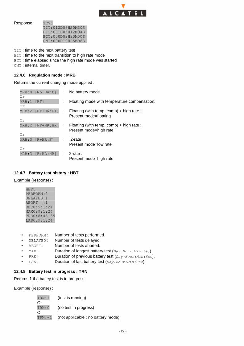
12.4.5 Timers : TCV
Example : TCV
- 22 -
Response : TCV:TIT:012D08H20M30SBIT:001D05H12M04SBCT:000D03H30M00SCNT:000D10H25M08S
TIT : time to the next battery testBIT : time to the next transition to high rate modeBCT : time elapsed since the high rate mode was startedCNT : internal timer.
12.4.6 Regulation mode : MRB
Returns the current charging mode applied :
MRB:0 [No Batt] : No battery modeOrMRB:1 [FT] : Floating mode with temperature compensation.OrMRB:2 [FT+HR:FT] : Floating (with temp. comp) + high rate :
Present mode=floatingOrMRB:2 [FT+HR:HR] : Floating (with temp. comp) + high rate :
Present mode=high rateOrMRB:3 [F+HR:F] : 2-rate :
Present mode=low rateOrMRB:3 [F+HR:HR] : 2-rate :
Present mode=high rate
12.4.7 Battery test history : HBT
Example (response) :
HBT:PERFORM:2DELAYED:1ABORT :1REF0:9:1:24MAX0:9:1:24PRE0:8:48:35LAS0:9:1:24
• PERFORM : Number of tests performed.• DELAYED : Number of tests delayed.• ABORT : Number of tests aborted.• MAX : Duration of longest battery test (Day:Hour:Min:Sec).• PRE : Duration of previous battery test (Day:Hour:Min:Sec).• LAS : Duration of last battery test (Day:Hour:Min:Sec).
12.4.8 Battery test in progress : TRN
Returns 1 if a battey test is in progress.
Example (response) :
TRN:1 (test is running)OrTRN:0 (no test in progress)OrTRN:-1 (not applicable : no battery mode).

- 23 -
12.5 Configuration commandsConfiguration commands are not described in this document.Use the Win1d Windows© based software to change the configuration.
Configuration parameters are :• Number of battery cells.• Shunt value.• Shunt configuration (on the load or on rectifiers’ output)• Input configuration for inputs Rect6/Spare8 to Rect10/Spare4 (rectifier input or spare input).• Logic of digital inputs.• Logic of digital outputs.• Regulation mode.• Current limits in float charge and high rate charge.• Low rate voltage.• Highrate voltage.• Voltage level in “No battery” mode.• Temperature compensation characteristics (slope, ..).• Temperature bounds for compensation.• High rate charge periodicity.• Current to switch from high rate charge to float charge.• High rate charge time-out.• Voltage level to open the non essential load contactor.• Voltage level to raise a “Battery voltage critical” alarm.• Voltage level to open the battery LVD.• Overvoltage alarm threshold.• Hysteresis to close the battery and load relays.• Logic to drive the battery and load relays.• Alarms filters for the digital outputs and the display.• Temperature thresholds to raise temperature alarm (2 thresholds).• Battery test current.• Battery test periodicity.

- 24 -
13 APPENDIX
13.1 ACM1D rear connector.
A B C1 GND2 ALM MainsFail+ GND ALM MainsFail-3 Output 3+ GND Output 3 -4 Output 1 + GND Output 1 -5 ALM Urgent+ GND ALM Urgent-6 ALM Non Urgent+ GND ALM Non Urgent-7 GND8 GND9 GND10 SH Bat- GND SH Bat+11 SH Load - GND SH Load+12 U Load - GND U Load+13 U Bat - GND U Bat+14 Temp- GND Temp+15 GND16 Battery Relay GND Load Relay (Aux.)17 GND18 GND19 Battery Fuse input20 Rect10/Spare Input 4 Spare Input 3 Load Fuse Input21 Rect7/Spare Input 7 Rect8/Spare Input 6 Rect9/Spare Input 522 Rect3 Rect2 Rect6/Spare Input 823 Rect1 Rect5 Rect424 Remote Off Output Main Fail Input Vadjust25 GND26 Spare Input 1 Spare Input 2 Output 22728 DC- DC- DC-29 GND30 DC+ (0V) DC + (0V) DC+ (0V)31 GND32 GND GND GND
GND is the ACM1D internal reference which is tied to the DC-.

- 25 -
13.2 SAFT POWER SYSTEMS SUBSIDIARIESARGENTINA / ARGENTINE
SAFT ARGENTINA S.AJose Leon Suarez 2244PO Box 14401440 BUENOS AIRESTel : + 54 11 4 686-1994Fax: + 54 11 4 686 -0270
AUSTRALIA / AUSTRALIE
SAFT Australia Pty LtdUnit 7, 20 Powers RoadPO Box 883SEVEN HILLS NSW 2147Tel : + 61 2 9674 0700Fax : + 61 2 9620 9990
BRAZIL / BRESIL
SAFT LtdaAV. Forte do Leme, 215Parque Industrial São Lourenço08340-010 SAO PAULO - SPTel : + 55 11 6100-6301Fax : + 55 11 6100-6363
CANADA / CANADA
SAFT Division125 NANTUCKET BlvdSCARBOROUGH,ONTARIO M1P 2N8Tel : + 1 416 757 51 51Fax : + 1 416 752 45 14
FRANCE / FRANCE
SAFT POWER SYSTEMSCustomer Service10, rue Jean PerrinBP 35937 173 CHAMBRAY LES TOURSTel : +33 (0)2 47 80 88 96Fax : +33 (0)2 47 80 88 38e-mail : [email protected]
GERMANY / ALLEMAGNE
AEG SVS PSG GmbHEmil Siepmann Strasse32D59581 WAERSTEIN-BELECKEGERMANYTel : + 49 2902 7630Fax : + 49 2902 763 680
HONG KONG / HONG KONG
SAFT Hong-Kong LtdUnit 1106-9 Westin Centre26 Hung to RoadKWUN TONGKOWLOONHONG-KONGTel : + 852 2796 9932Fax : + 852 2798 0619
ITALY / ITALIE
SAFT S.p.AViale Cembrano, 11Casella Postale 128316148 GENOVATel : + 39 0 10 37 47 911Fax : + 39 0 10 38 62 73
KOREA / COREE
SAFT Korea Co Ltd#195-42, Anyang 7-DongManan-Ku, Anyang CityKYUNGGI-DOTel : + 82 343 41 1134Fax : + 82 343 41 1139

- 26 -
MALAYSIA / MALAISIE
SAFT Power Systems Sdn BhdN°37, Jalan 10/91 Taman Shamelin Perkasa Batu 3 1/2 Jalan Cheras56100 KUALA LUMPURTel : + 60 3 985 29 96Fax : + 60 3 984 49 95
MEXICO / MEXIQUE
SAFT S.A. de CVCamos Eliseos N° 385Torre A Piso 11Col. PolancoMEXICO D.F CP 11560Tel : + 525 280 0619Fax : + 525 280 3559
MIDDLE-EAST / MOYEN-ORIENT
SAFT M.E. LtdPO Box 543073723 LIMASSOLCYPRUSTel : + 357 53 40 637Fax : + 357 57 48 492
NETHERLANDS / PAYS BAS
SAFT B.VPO Box 821160 AB ZWANENBURGTel : + 31 (0) 20 407 78 00Fax : + 31 (0) 20 407 78 01
SINGAPORE / SINGAPOUR
SAFT Power Systems Pte Ltd54 Genting Lane Hiang Kie Complex II#03-01/03 - SINGAPORE 349562Tel : + 65 846 5736Fax : + 65 743 1037
SPAIN / ESPAGNE
SAFT Iberica SLVitorialanda, 4-601010 VITORIA-GASTEIZTel : + 34 945 21 41 10Fax : + 34 945 21 41 11
SWEDEN / SUEDE
SAFT ABPO BOX 4121SE 171-04 SOLNASWEDENTel : + 46 8 598 49750Fax : + 46 8 598 49755
UNITED KINGDOM / ROYAUME UNI
SAFT LtdPeregrine Road,HAINAULT, ILFORDEssex IG6 3XJTel : + 44 181 500 1211Fax : + 44 181 500 9365
USA / ETATS-UNIS
ALCAD INDUSTRIAL AND RAILWAY BATTERIES73, Defco Park RoadWharton BrookIndustrial ParkNORTH HAVEN,CONNECTICUT 06473Tel : + 1 203 234 83 33Fax : + 1 203 234 82 55