towards passive 6d reflectance field displaysmajumder/comppc/papers/6d-displays.pdftowards passive...
TRANSCRIPT
To appear in the ACM SIGGRAPH conference proceedings
Towards P assive 6D Reflectance Field Displays
Martin Fuchs∗
MPI InformatikRamesh Raskar†
Mitsubishi Electric Research LaboratoriesHans-Peter Seidel∗
MPI InformatikHendrik P. A. Lensch∗
MPI Informatik
Abstract
Traditional flat screen displays present 2D images. 3D and 4D dis-plays have been proposed making use of lenslet arrays to shape afixed outgoing light field for horizontal or bidirectional parallax. Inthis article, we present different designs of multi-dimensional dis-plays which passively react to the light of the environment behind.The prototypes physically implement a reflectance field and gen-erate different light fields depending on the incident illumination,for example light falling through a window. We discretize the in-cident light field using an optical system, and modulate it with a2D pattern, creating a flat display which is viewand illumination-dependent. It is free from electronic components. For distant lightand a fixed observer position, we demonstrate a passive optical con-figuration which directly renders a 4D reflectance field in the real-world illumination behind it. We further propose an optical setupthat allows for projecting out different angular distributions depend-ing on the incident light direction. Combining multiple of these de-vices we build a display that renders a 6D experience, where theincident 2D illumination influences the outgoing light field, both inthe spatial and in the angular domain. Possible applications of thistechnology are time-dependent displays driven by sunlight, objectvirtualization and programmable light benders / ray blockers with-out moving parts.
CR Categories: I.4.0 [Image Processing and Computer Vi-sion]: General—Image displays I.4.1 [Image Processing and Com-puter Vision]: Digitization and Image Capture—Reflectance I.3.7[Computer Graphics]: Three-Dimensional Graphics and Realism—Color, shading, shadowing, and texture
Keywords: passive reflectance field display, image-based relight-ing with natural light
1 Introduction
For centuries, there has been technology available to create stainedglass – glass which emits a picture by modulating the incident illu-mination. In this article, we extend this concept to a new kind ofdisplays that renders different images or even light fields depend-ing on ambient illumination. The display for example can showa relightable scene model, rendering this scene in the illuminationwhich is incident to the display from behind (see Figure 1), e.g. innatural lighting outside a window. Illumination dependent effectssuch as shadows and highlights will change accordingly.
∗e-mail:mfuchs,hpseidel,[email protected]†now at MIT Media Lab, e-mail:[raskar]@media.mit.edu
area distant top red and green overcast
time lapse
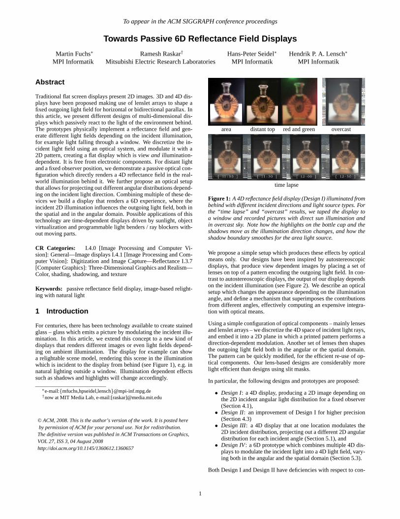
Figure 1: A 4Dreflectance field display (Design I) illuminated frombehind with different incident directions and light source types. Forthe “time lapse” and “overcast” results, we taped the display toa window and recorded pictures with direct sun illumination andin overcast sky. Note how the highlights on the bottle cap and theshadows move as the illumination direction changes, and how theshadow boundary smoothes for the area light source.
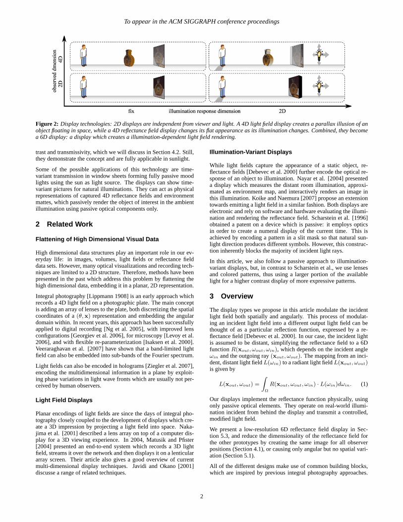
We propose a simple setup which produces these effects by opticalmeans only. Our designs have been inspired by autostereoscopicdisplays, that produce view dependent images by placing a set oflenses on top of a pattern encoding the outgoing light field. In con-trast to autostereoscopic displays, the output of our display dependson the incident illumination (see Figure 2). We describe an opticalsetup which changes the appearance depending on the illuminationangle, and define a mechanism that superimposes the contributionsfrom different angles, effectively computing an expensive integra-tion with optical means.
Using a simple configuration of optical components – mainly lensesand lenslet arrays – we discretize the 4D space of incident light rays,and embed it into a 2D plane in which a printed pattern performs adirection-dependent modulation. Another set of lenses then shapesthe outgoing light field both in the angular or the spatial domain.The pattern can be quickly modified, for the efficient re-use of op-tical components. Our lens-based designs are considerably morelight efficient than designs using slit masks.
In particular, the following designs and prototypes are proposed:
• Design I: a 4D display, producing a 2D image depending onthe 2D incident angular light distribution for a fixed observer(Section 4.1),
• Design II: an improvement of Design I for higher precision(Section 4.3)
• Design III: a 4D display that at one location modulates the2D incident distribution, projecting out a different 2D angulardistribution for each incident angle (Section 5.1), and
• Design IV: a 6D prototype which combines multiple 4D dis-plays to modulate the incident light into a 4D light field, vary-ing both in the angular and the spatial domain (Section 5.3).
Both Design I and Design II have deficiencies with respect to con-
1
© ACM, 2008. This is the author’s version of the work. It is posted here by permission of ACM for your personal use. Not for redistribution. The definitive version was published in ACM Transactions on Graphics, VOL 27, ISS 3, 04 August 2008http://doi.acm.org/10.1145/1360612.1360657
To appear in the ACM SIGGRAPH conference proceedings
Figure 2: Display technologies: 2D displays are independent from viewer and light. A4D light field display creates a parallax illusion of anobject floating in space, while a 4D reflectance field display changes its flatappearance as its illumination changes. Combined, they becomea 6D display: a display which creates a illumination-dependent light field rendering.
trast and transmissivity, which we will discuss in Section 4.2. Still,they demonstrate the concept and are fully applicable in sunlight.
Some of the possible applications of this technology are time-variant transmission in window sheets forming fully passive moodlights using the sun as light source. The displays can show time-variant pictures for natural illuminations. They can act as physicalrepresentations of captured 4D reflectance fields and environmentmattes, which passively render the object of interest in the ambientillumination using passive optical components only.
2 Related Work
Flattening of High Dimensional Visual Data
High dimensional data structures play an important role in our ev-eryday life: in images, volumes, light fields or reflectance fielddata sets. However, many optical visualizations and recording tech-niques are limited to a 2D structure. Therefore, methods have beenpresented in the past which address this problem by flattening thehigh dimensional data, embedding it in a planar, 2D representation.
Integral photography [Lippmann 1908] is an early approach whichrecords a 4D light field on a photographic plate. The main conceptis adding an array of lenses to the plate, both discretizing the spatialcoordinates of a(θ,x) representation and embedding the angulardomain within. In recent years, this approach has been successfullyapplied to digital recording [Ng et al. 2005], with improved lensconfigurations [Georgiev et al. 2006], for microscopy [Levoy et al.2006], and with flexible re-parameterization [Isaksen et al. 2000].Veeraraghavan et al. [2007] have shown that a band-limited lightfield can also be embedded into sub-bands of the Fourier spectrum.
Light fields can also be encoded in holograms [Ziegler et al. 2007],encoding the multidimensional information in a plane by exploit-ing phase variations in light wave fronts which are usually not per-ceived by human observers.
Light Field Displays
Planar encodings of light fields are since the days of integral pho-tography closely coupled to the development of displays which cre-ate a 3D impression by projecting a light field into space. Naka-jima et al. [2001] described a lens array on top of a computer dis-play for a 3D viewing experience. In 2004, Matusik and Pfister[2004] presented an end-to-end system which records a 3D lightfield, streams it over the network and then displays it on a lenticulararray screen. Their article also gives a good overview of currentmulti-dimensional display techniques. Javidi and Okano [2001]discusse a range of related techniques.
Illumination-Variant Displays
While light fields capture the appearance of a static object, re-flectance fields [Debevec et al. 2000] further encode the optical re-sponse of an object to illumination. Nayar et al. [2004] presenteda display which measures the distant room illumination, approxi-mated as environment map, and interactively renders an image inthis illumination. Koike and Naemura [2007] propose an extensiontowards emitting a light field in a similar fashion. Both displays areelectronic and rely on software and hardware evaluating the illumi-nation and rendering the reflectance field. Scharstein et al. [1996]obtained a patent on a device which is passive: it employs opticsin order to create a numeral display of the current time. This isachieved by encoding a pattern in a slit mask so that natural sun-light direction produces different symbols. However, this construc-tion inherently blocks the majority of incident light rays.
In this article, we also follow a passive approach to illumination-variant displays, but, in contrast to Scharstein et al., we use lensesand colored patterns, thus using a larger portion of the availablelight for a higher contrast display of more expressive patterns.
3 Overview
The display types we propose in this article modulate the incidentlight field both spatially and angularly. This process of modulat-ing an incident light field into a different output light field can bethought of as a particular reflection function, expressed by a re-flectance field [Debevec et al. 2000]. In our case, the incident lightis assumed to be distant, simplifying the reflectance field to a 6DfunctionR(xout, ωout, ωin), which depends on the incident angleωin and the outgoing ray(xout, ωout). The mapping from an inci-dent, distant light fieldL(ωin) to a radiant light fieldL(xout, ωout)is given by
L(xout, ωout) =
∫Ω
R(xout, ωout, ωin) · L(ωin)dωin. (1)
Our displays implement the reflectance function physically, usingonly passive optical elements. They operate on real-world illumi-nation incident from behind the display and transmit a controlled,modified light field.
We present a low-resolution 6D reflectance field display in Sec-tion 5.3, and reduce the dimensionality of the reflectance field forthe other prototypes by creating the same image for all observerpositions (Section 4.1), or causing only angular but no spatial vari-ation (Section 5.1).
All of the different designs make use of common building blocks,which are inspired by previous integral photography approaches.
2
To appear in the ACM SIGGRAPH conference proceedings
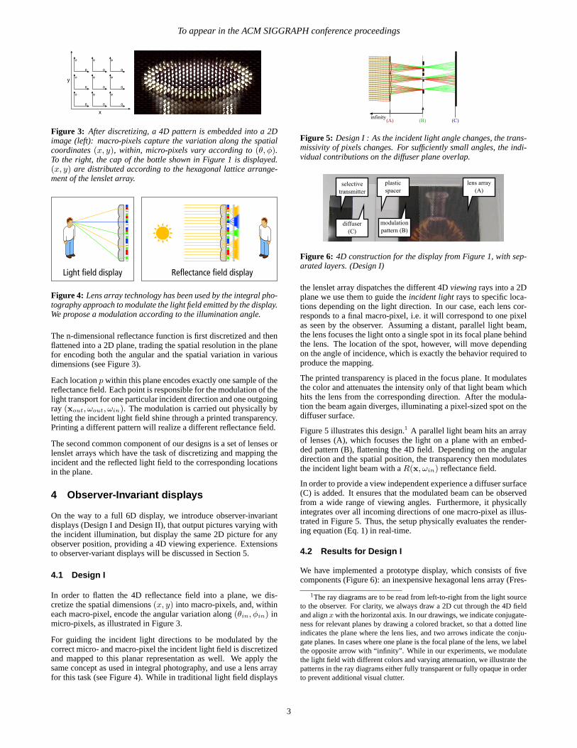
Figure 3: After discretizing, a 4D pattern is embedded into a 2Dimage (left): macro-pixels capture the variation along the spatialcoordinates(x, y), within, micro-pixels vary according to(θ, φ).To the right, the cap of the bottle shown in Figure 1 is displayed.(x, y) are distributed according to the hexagonal lattice arrange-ment of the lenslet array.
Figure 4: Lens array technology has been used by the integral pho-tography approach to modulate the light field emitted by the display.We propose a modulation according to the illumination angle.
The n-dimensional reflectance function is first discretized and thenflattened into a 2D plane, trading the spatial resolution in the planefor encoding both the angular and the spatial variation in variousdimensions (see Figure 3).
Each locationp within this plane encodes exactly one sample of thereflectance field. Each point is responsible for the modulation of thelight transport for one particular incident direction and one outgoingray (xout, ωout, ωin). The modulation is carried out physically byletting the incident light field shine through a printed transparency.Printing a different pattern will realize a different reflectance field.
The second common component of our designs is a set of lenses orlenslet arrays which have the task of discretizing and mapping theincident and the reflected light field to the corresponding locationsin the plane.
4 Observer-Invariant displays
On the way to a full 6D display, we introduce observer-invariantdisplays (Design I and Design II), that output pictures varying withthe incident illumination, but display the same 2D picture for anyobserver position, providing a 4D viewing experience. Extensionsto observer-variant displays will be discussed in Section 5.
4.1 Design I
In order to flatten the 4D reflectance field into a plane, we dis-cretize the spatial dimensions(x, y) into macro-pixels, and, withineach macro-pixel, encode the angular variation along(θin, φin) inmicro-pixels, as illustrated in Figure 3.
For guiding the incident light directions to be modulated by thecorrect micro- and macro-pixel the incident light field is discretizedand mapped to this planar representation as well. We apply thesame concept as used in integral photography, and use a lens arrayfor this task (see Figure 4). While in traditional light field displays
Figure 5: Design I : As the incident light angle changes, the trans-missivity of pixels changes. For sufficiently small angles, the indi-vidual contributions on the diffuser plane overlap.
Figure 6: 4D construction for the display from Figure 1, with sep-arated layers. (Design I)
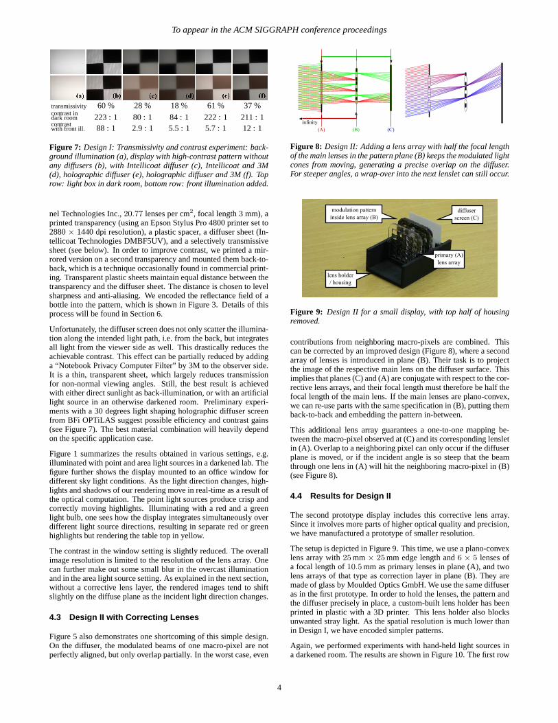
the lenslet array dispatches the different 4Dviewingrays into a 2Dplane we use them to guide theincident lightrays to specific loca-tions depending on the light direction. In our case, each lens cor-responds to a final macro-pixel, i.e. it will correspond to one pixelas seen by the observer. Assuming a distant, parallel light beam,the lens focuses the light onto a single spot in its focal plane behindthe lens. The location of the spot, however, will move dependingon the angle of incidence, which is exactly the behavior required toproduce the mapping.
The printed transparency is placed in the focus plane. It modulatesthe color and attenuates the intensity only of that light beam whichhits the lens from the corresponding direction. After the modula-tion the beam again diverges, illuminating a pixel-sized spot on thediffuser surface.
Figure 5 illustrates this design.1 A parallel light beam hits an arrayof lenses (A), which focuses the light on a plane with an embed-ded pattern (B), flattening the 4D field. Depending on the angulardirection and the spatial position, the transparency then modulatesthe incident light beam with aR(x, ωin) reflectance field.
In order to provide a view independent experience a diffuser surface(C) is added. It ensures that the modulated beam can be observedfrom a wide range of viewing angles. Furthermore, it physicallyintegrates over all incoming directions of one macro-pixel as illus-trated in Figure 5. Thus, the setup physically evaluates the render-ing equation (Eq. 1) in real-time.
4.2 Results for Design I
We have implemented a prototype display, which consists of fivecomponents (Figure 6): an inexpensive hexagonal lens array (Fres-
1The ray diagrams are to be read from left-to-right from the light sourceto the observer. For clarity, we always draw a 2D cut through the 4D fieldand alignx with the horizontal axis. In our drawings, we indicate conjugate-ness for relevant planes by drawing a colored bracket, so that a dotted lineindicates the plane where the lens lies, and two arrows indicate the conju-gate planes. In cases where one plane is the focal plane of thelens, we labelthe opposite arrow with “infinity”. While in our experiments, we modulatethe light field with different colors and varying attenuation, we illustrate thepatterns in the ray diagrams either fully transparent or fully opaque in orderto prevent additional visual clutter.
3
To appear in the ACM SIGGRAPH conference proceedings
transmissivity 60 % 28 % 18 % 61 % 37 %contrast indark room 223 : 1 80 : 1 84 : 1 222 : 1 211 : 1contrastwith front ill. 88 : 1 2.9 : 1 5.5 : 1 5.7 : 1 12 : 1
Figure 7: Design I: Transmissivity and contrast experiment: back-ground illumination (a), display with high-contrast pattern withoutany diffusers (b), with Intellicoat diffuser (c), Intellicoat and 3M(d), holographic diffuser (e), holographic diffuser and 3M (f). Toprow: light box in dark room, bottom row: front illumination added.
nel Technologies Inc.,20.77 lenses per cm2, focal length3 mm), aprinted transparency (using an Epson Stylus Pro 4800 printer set to2880× 1440 dpi resolution), a plastic spacer, a diffuser sheet (In-tellicoat Technologies DMBF5UV), and a selectively transmissivesheet (see below). In order to improve contrast, we printed a mir-rored version on a second transparency and mounted them back-to-back, which is a technique occasionally found in commercial print-ing. Transparent plastic sheets maintain equal distance between thetransparency and the diffuser sheet. The distance is chosen to levelsharpness and anti-aliasing. We encoded the reflectance field of abottle into the pattern, which is shown in Figure 3. Details of thisprocess will be found in Section 6.
Unfortunately, the diffuser screen does not only scatter the illumina-tion along the intended light path, i.e. from the back, but integratesall light from the viewer side as well. This drastically reduces theachievable contrast. This effect can be partially reduced by addinga “Notebook Privacy Computer Filter” by 3M to the observer side.It is a thin, transparent sheet, which largely reduces transmissionfor non-normal viewing angles. Still, the best result is achievedwith either direct sunlight as back-illumination, or with an artificiallight source in an otherwise darkened room. Preliminary experi-ments with a 30 degrees light shaping holographic diffuser screenfrom BFi OPTiLAS suggest possible efficiency and contrast gains(see Figure 7). The best material combination will heavily dependon the specific application case.
Figure 1 summarizes the results obtained in various settings, e.g.illuminated with point and area light sources in a darkened lab. Thefigure further shows the display mounted to an office window fordifferent sky light conditions. As the light direction changes, high-lights and shadows of our rendering move in real-time as a result ofthe optical computation. The point light sources produce crisp andcorrectly moving highlights. Illuminating with a red and a greenlight bulb, one sees how the display integrates simultaneously overdifferent light source directions, resulting in separate red or greenhighlights but rendering the table top in yellow.
The contrast in the window setting is slightly reduced. The overallimage resolution is limited to the resolution of the lens array. Onecan further make out some small blur in the overcast illuminationand in the area light source setting. As explained in the next section,without a corrective lens layer, the rendered images tend to shiftslightly on the diffuse plane as the incident light direction changes.
4.3 Design II with Correcting Lenses
Figure 5 also demonstrates one shortcoming of this simple design.On the diffuser, the modulated beams of one macro-pixel are notperfectly aligned, but only overlap partially. In the worst case, even
Figure 8: Design II: Adding a lens array with half the focal lengthof the main lenses in the pattern plane (B) keeps the modulated lightcones from moving, generating a precise overlap on the diffuser.For steeper angles, a wrap-over into the next lenslet can still occur.
Figure 9: Design II for a small display, with top half of housingremoved.
contributions from neighboring macro-pixels are combined. Thiscan be corrected by an improved design (Figure 8), where a secondarray of lenses is introduced in plane (B). Their task is to projectthe image of the respective main lens on the diffuser surface. Thisimplies that planes (C) and (A) are conjugate with respect to the cor-rective lens arrays, and their focal length must therefore be half thefocal length of the main lens. If the main lenses are plano-convex,we can re-use parts with the same specification in (B), putting themback-to-back and embedding the pattern in-between.
This additional lens array guarantees a one-to-one mapping be-tween the macro-pixel observed at (C) and its corresponding lensletin (A). Overlap to a neighboring pixel can only occur if the diffuserplane is moved, or if the incident angle is so steep that the beamthrough one lens in (A) will hit the neighboring macro-pixel in (B)(see Figure 8).
4.4 Results for Design II
The second prototype display includes this corrective lens array.Since it involves more parts of higher optical quality and precision,we have manufactured a prototype of smaller resolution.
The setup is depicted in Figure 9. This time, we use a plano-convexlens array with25 mm× 25 mm edge length and6 × 5 lenses ofa focal length of10.5 mm as primary lenses in plane (A), and twolens arrays of that type as correction layer in plane (B). They aremade of glass by Moulded Optics GmbH. We use the same diffuseras in the first prototype. In order to hold the lenses, the pattern andthe diffuser precisely in place, a custom-built lens holder has beenprinted in plastic with a 3D printer. This lens holder also blocksunwanted stray light. As the spatial resolution is much lower thanin Design I, we have encoded simpler patterns.
Again, we performed experiments with hand-held light sources ina darkened room. The results are shown in Figure 10. The first row
4
To appear in the ACM SIGGRAPH conference proceedings
pattern resulting pictures
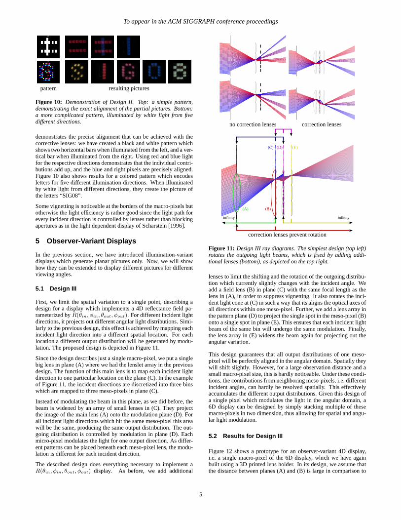
Figure 10: Demonstration of Design II. Top: a simple pattern,demonstrating the exact alignment of the partial pictures. Bottom:a more complicated pattern, illuminated by white light from fivedifferent directions.
demonstrates the precise alignment that can be achieved with thecorrective lenses: we have created a black and white pattern whichshows two horizontal bars when illuminated from the left, and a ver-tical bar when illuminated from the right. Using red and blue lightfor the respective directions demonstrates that the individual contri-butions add up, and the blue and right pixels are precisely aligned.Figure 10 also shows results for a colored pattern which encodesletters for five different illumination directions. When illuminatedby white light from different directions, they create the picture ofthe letters “SIG08”.
Some vignetting is noticeable at the borders of the macro-pixels butotherwise the light efficiency is rather good since the light path forevery incident direction is controlled by lenses rather than blockingapertures as in the light dependent display of Scharstein [1996].
5 Observer-Variant Displays
In the previous section, we have introduced illumination-variantdisplays which generate planar pictures only. Now, we will showhow they can be extended to display different pictures for differentviewing angles.
5.1 Design III
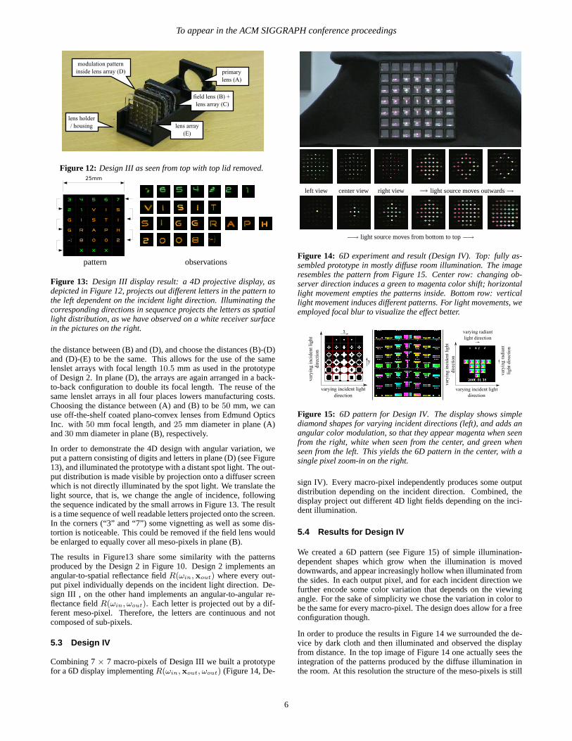
First, we limit the spatial variation to a single point, describing adesign for a display which implements a 4D reflectance field pa-rameterized byR(θin, φin, θout, φout). For different incident lightdirections, it projects out different angular light distributions. Simi-larly to the previous design, this effect is achieved by mapping eachincident light direction into a different spatial location. For eachlocation a different output distribution will be generated by modu-lation. The proposed design is depicted in Figure 11.
Since the design describes just a single macro-pixel, we put a singlebig lens in plane (A) where we had the lenslet array in the previousdesign. The function of this main lens is to map each incident lightdirection to one particular location on the plane (C). In the exampleof Figure 11, the incident directions are discretized into three binswhich are mapped to three meso-pixels in plane (C).
Instead of modulating the beam in this plane, as we did before, thebeam is widened by an array of small lenses in (C). They projectthe image of the main lens (A) onto the modulation plane (D). Forall incident light directions which hit the same meso-pixel this areawill be the same, producing the same output distribution. The out-going distribution is controlled by modulation in plane (D). Eachmicro-pixel modulates the light for one output direction. As differ-ent patterns can be placed beneath each meso-pixel lens, the modu-lation is different for each incident direction.
The described design does everything necessary to implement aR(θin, φin, θout, φout) display. As before, we add additional
no correction lenses correction lenses
correction lenses prevent rotation
Figure 11: Design III ray diagrams. The simplest design (top left)rotates the outgoing light beams, which is fixed by adding addi-tional lenses (bottom), as depicted on the top right.
lenses to limit the shifting and the rotation of the outgoing distribu-tion which currently slightly changes with the incident angle. Weadd a field lens (B) in plane (C) with the same focal length as thelens in (A), in order to suppress vignetting. It also rotates the inci-dent light cone at (C) in such a way that its aligns the optical axes ofall directions within one meso-pixel. Further, we add a lens array inthe pattern plane (D) to project the single spot in the meso-pixel (B)onto a single spot in plane (E). This ensures that each incident lightbeam of the same bin will undergo the same modulation. Finally,the lens array in (E) widens the beam again for projecting out theangular variation.
This design guarantees that all output distributions of one meso-pixel will be perfectly aligned in the angular domain. Spatially theywill shift slightly. However, for a large observation distance and asmall macro-pixel size, this is hardly noticeable. Under these condi-tions, the contributions from neighboring meso-pixels, i.e. differentincident angles, can hardly be resolved spatially. This effectivelyaccumulates the different output distributions. Given this design ofa single pixel which modulates the light in the angular domain, a6D display can be designed by simply stacking multiple of thesemacro-pixels in two dimension, thus allowing for spatial and angu-lar light modulation.
5.2 Results for Design III
Figure 12 shows a prototype for an observer-variant 4D display,i.e. a single macro-pixel of the 6D display, which we have againbuilt using a 3D printed lens holder. In its design, we assume thatthe distance between planes (A) and (B) is large in comparison to
5
To appear in the ACM SIGGRAPH conference proceedings
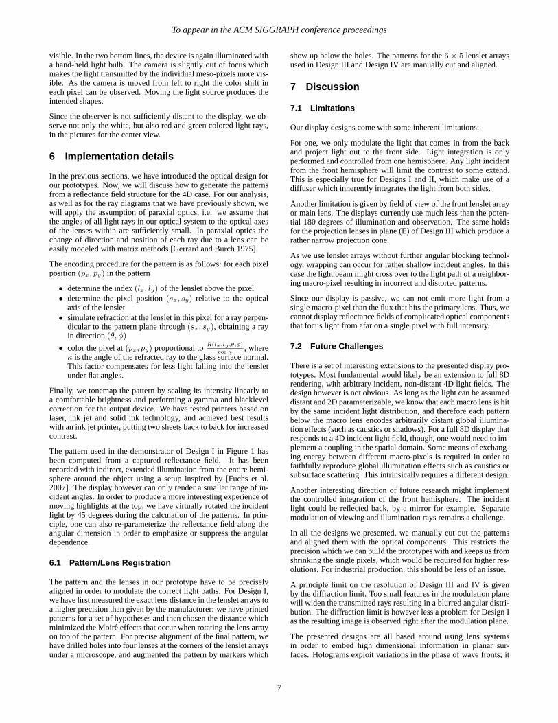
Figure 12: Design III as seen from top with top lid removed.
pattern observations
Figure 13: Design III display result: a 4D projective display, asdepicted in Figure 12, projects out different letters in the pattern tothe left dependent on the incident light direction. Illuminating thecorresponding directions in sequence projects the letters as spatiallight distribution, as we have observed on a white receiver surfacein the pictures on the right.
the distance between (B) and (D), and choose the distances (B)-(D)and (D)-(E) to be the same. This allows for the use of the samelenslet arrays with focal length10.5 mm as used in the prototypeof Design 2. In plane (D), the arrays are again arranged in a back-to-back configuration to double its focal length. The reuse of thesame lenslet arrays in all four places lowers manufacturing costs.Choosing the distance between (A) and (B) to be50 mm, we canuse off-the-shelf coated plano-convex lenses from Edmund OpticsInc. with 50 mm focal length, and25 mm diameter in plane (A)and30 mm diameter in plane (B), respectively.
In order to demonstrate the 4D design with angular variation, weput a pattern consisting of digits and letters in plane (D) (see Figure13), and illuminated the prototype with a distant spot light. The out-put distribution is made visible by projection onto a diffuser screenwhich is not directly illuminated by the spot light. We translate thelight source, that is, we change the angle of incidence, followingthe sequence indicated by the small arrows in Figure 13. The resultis a time sequence of well readable letters projected onto the screen.In the corners (“3” and “7”) some vignetting as well as some dis-tortion is noticeable. This could be removed if the field lens wouldbe enlarged to equally cover all meso-pixels in plane (B).
The results in Figure13 share some similarity with the patternsproduced by the Design 2 in Figure 10. Design 2 implements anangular-to-spatial reflectance fieldR(ωin,xout) where every out-put pixel individually depends on the incident light direction. De-sign III , on the other hand implements an angular-to-angular re-flectance fieldR(ωin, ωout). Each letter is projected out by a dif-ferent meso-pixel. Therefore, the letters are continuous and notcomposed of sub-pixels.
5.3 Design IV
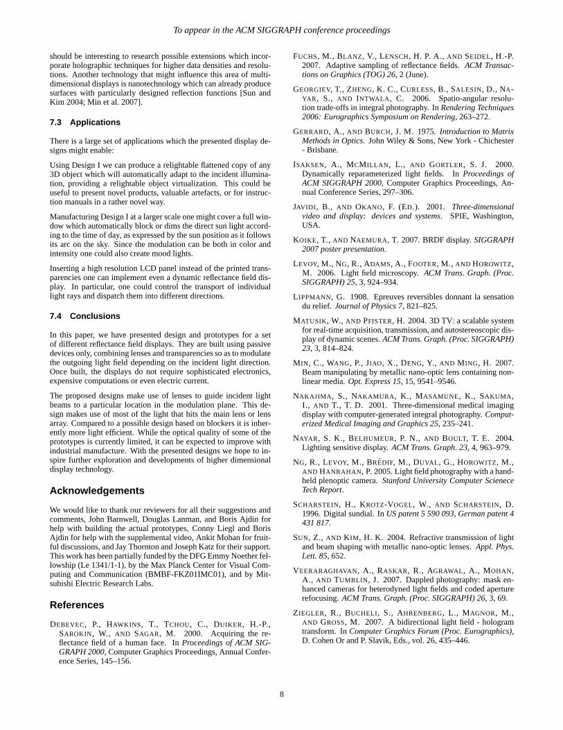
Combining 7× 7 macro-pixels of Design III we built a prototypefor a 6D display implementingR(ωin,xout, ωout) (Figure 14, De-
left view center view right view → light source moves outwards→
−→ light source moves from bottom to top−→
Figure 14: 6D experiment and result (Design IV). Top: fully as-sembled prototype in mostly diffuse room illumination. The imageresembles the pattern from Figure 15. Center row: changing ob-server direction induces a green to magenta color shift; horizontallight movement empties the patterns inside. Bottom row: verticallight movement induces different patterns. For light movements, weemployed focal blur to visualize the effect better.
Figure 15: 6D pattern for Design IV. The display shows simplediamond shapes for varying incident directions (left), and adds anangular color modulation, so that they appear magenta when seenfrom the right, white when seen from the center, and green whenseen from the left. This yields the 6D pattern in the center, with asingle pixel zoom-in on the right.
sign IV). Every macro-pixel independently produces some outputdistribution depending on the incident direction. Combined, thedisplay project out different 4D light fields depending on the inci-dent illumination.
5.4 Results for Design IV
We created a 6D pattern (see Figure 15) of simple illumination-dependent shapes which grow when the illumination is moveddownwards, and appear increasingly hollow when illuminated fromthe sides. In each output pixel, and for each incident direction wefurther encode some color variation that depends on the viewingangle. For the sake of simplicity we chose the variation in color tobe the same for every macro-pixel. The design does allow for a freeconfiguration though.
In order to produce the results in Figure 14 we surrounded the de-vice by dark cloth and then illuminated and observed the displayfrom distance. In the top image of Figure 14 one actually sees theintegration of the patterns produced by the diffuse illumination inthe room. At this resolution the structure of the meso-pixels is still
6
To appear in the ACM SIGGRAPH conference proceedings
visible. In the two bottom lines, the device is again illuminated witha hand-held light bulb. The camera is slightly out of focus whichmakes the light transmitted by the individual meso-pixels more vis-ible. As the camera is moved from left to right the color shift ineach pixel can be observed. Moving the light source produces theintended shapes.
Since the observer is not sufficiently distant to the display, we ob-serve not only the white, but also red and green colored light rays,in the pictures for the center view.
6 Implementation details
In the previous sections, we have introduced the optical design forour prototypes. Now, we will discuss how to generate the patternsfrom a reflectance field structure for the 4D case. For our analysis,as well as for the ray diagrams that we have previously shown, wewill apply the assumption of paraxial optics, i.e. we assume thatthe angles of all light rays in our optical system to the optical axesof the lenses within are sufficiently small. In paraxial optics thechange of direction and position of each ray due to a lens can beeasily modeled with matrix methods [Gerrard and Burch 1975].
The encoding procedure for the pattern is as follows: for each pixelposition(px, py) in the pattern
• determine the index(lx, ly) of the lenslet above the pixel• determine the pixel position(sx, sy) relative to the optical
axis of the lenslet• simulate refraction at the lenslet in this pixel for a ray perpen-
dicular to the pattern plane through(sx, sy), obtaining a rayin direction(θ, φ)
• color the pixel at(px, py) proportional toR(lx,ly,θ,φ)
cos κ, where
κ is the angle of the refracted ray to the glass surface normal.This factor compensates for less light falling into the lensletunder flat angles.
Finally, we tonemap the pattern by scaling its intensity linearly toa comfortable brightness and performing a gamma and blacklevelcorrection for the output device. We have tested printers based onlaser, ink jet and solid ink technology, and achieved best resultswith an ink jet printer, putting two sheets back to back for increasedcontrast.
The pattern used in the demonstrator of Design I in Figure 1 hasbeen computed from a captured reflectance field. It has beenrecorded with indirect, extended illumination from the entire hemi-sphere around the object using a setup inspired by [Fuchs et al.2007]. The display however can only render a smaller range of in-cident angles. In order to produce a more interesting experience ofmoving highlights at the top, we have virtually rotated the incidentlight by 45 degrees during the calculation of the patterns. In prin-ciple, one can also re-parameterize the reflectance field along theangular dimension in order to emphasize or suppress the angulardependence.
6.1 Pattern/Lens Registration
The pattern and the lenses in our prototype have to be preciselyaligned in order to modulate the correct light paths. For Design I,we have first measured the exact lens distance in the lenslet arrays toa higher precision than given by the manufacturer: we have printedpatterns for a set of hypotheses and then chosen the distance whichminimized the Moire effects that occur when rotating the lens arrayon top of the pattern. For precise alignment of the final pattern, wehave drilled holes into four lenses at the corners of the lenslet arraysunder a microscope, and augmented the pattern by markers which
show up below the holes. The patterns for the6 × 5 lenslet arraysused in Design III and Design IV are manually cut and aligned.
7 Discussion
7.1 Limitations
Our display designs come with some inherent limitations:
For one, we only modulate the light that comes in from the backand project light out to the front side. Light integration is onlyperformed and controlled from one hemisphere. Any light incidentfrom the front hemisphere will limit the contrast to some extend.This is especially true for Designs I and II, which make use of adiffuser which inherently integrates the light from both sides.
Another limitation is given by field of view of the front lenslet arrayor main lens. The displays currently use much less than the poten-tial 180 degrees of illumination and observation. The same holdsfor the projection lenses in plane (E) of Design III which produce arather narrow projection cone.
As we use lenslet arrays without further angular blocking technol-ogy, wrapping can occur for rather shallow incident angles. In thiscase the light beam might cross over to the light path of a neighbor-ing macro-pixel resulting in incorrect and distorted patterns.
Since our display is passive, we can not emit more light from asingle macro-pixel than the flux that hits the primary lens. Thus, wecannot display reflectance fields of complicated optical componentsthat focus light from afar on a single pixel with full intensity.
7.2 Future Challenges
There is a set of interesting extensions to the presented display pro-totypes. Most fundamental would likely be an extension to full 8Drendering, with arbitrary incident, non-distant 4D light fields. Thedesign however is not obvious. As long as the light can be assumeddistant and 2D parameterizable, we know that each macro lens is hitby the same incident light distribution, and therefore each patternbelow the macro lens encodes arbitrarily distant global illumina-tion effects (such as caustics or shadows). For a full 8D display thatresponds to a 4D incident light field, though, one would need to im-plement a coupling in the spatial domain. Some means of exchang-ing energy between different macro-pixels is required in order tofaithfully reproduce global illumination effects such as caustics orsubsurface scattering. This intrinsically requires a different design.
Another interesting direction of future research might implementthe controlled integration of the front hemisphere. The incidentlight could be reflected back, by a mirror for example. Separatemodulation of viewing and illumination rays remains a challenge.
In all the designs we presented, we manually cut out the patternsand aligned them with the optical components. This restricts theprecision which we can build the prototypes with and keeps us fromshrinking the single pixels, which would be required for higher res-olutions. For industrial production, this should be less of an issue.
A principle limit on the resolution of Design III and IV is givenby the diffraction limit. Too small features in the modulation planewill widen the transmitted rays resulting in a blurred angular distri-bution. The diffraction limit is however less a problem for Design Ias the resulting image is observed right after the modulation plane.
The presented designs are all based around using lens systemsin order to embed high dimensional information in planar sur-faces. Holograms exploit variations in the phase of wave fronts; it
7
To appear in the ACM SIGGRAPH conference proceedings
should be interesting to research possible extensions which incor-porate holographic techniques for higher data densities and resolu-tions. Another technology that might influence this area of multi-dimensional displays is nanotechnology which can already producesurfaces with particularly designed reflection functions [Sun andKim 2004; Min et al. 2007].
7.3 Applications
There is a large set of applications which the presented display de-signs might enable:
Using Design I we can produce a relightable flattened copy of any3D object which will automatically adapt to the incident illumina-tion, providing a relightable object virtualization. This could beuseful to present novel products, valuable artefacts, or for instruc-tion manuals in a rather novel way.
Manufacturing Design I at a larger scale one might cover a full win-dow which automatically block or dims the direct sun light accord-ing to the time of day, as expressed by the sun position as it followsits arc on the sky. Since the modulation can be both in color andintensity one could also create mood lights.
Inserting a high resolution LCD panel instead of the printed trans-parencies one can implement even a dynamic reflectance field dis-play. In particular, one could control the transport of individuallight rays and dispatch them into different directions.
7.4 Conclusions
In this paper, we have presented design and prototypes for a setof different reflectance field displays. They are built using passivedevices only, combining lenses and transparencies so as to modulatethe outgoing light field depending on the incident light direction.Once built, the displays do not require sophisticated electronics,expensive computations or even electric current.
The proposed designs make use of lenses to guide incident lightbeams to a particular location in the modulation plane. This de-sign makes use of most of the light that hits the main lens or lensarray. Compared to a possible design based on blockers it is inher-ently more light efficient. While the optical quality of some of theprototypes is currently limited, it can be expected to improve withindustrial manufacture. With the presented designs we hope to in-spire further exploration and developments of higher dimensionaldisplay technology.
Acknowledgements
We would like to thank our reviewers for all their suggestions andcomments, John Barnwell, Douglas Lanman, and Boris Ajdin forhelp with building the actual prototypes, Conny Liegl and BorisAjdin for help with the supplemental video, Ankit Mohan for fruit-ful discussions, and Jay Thornton and Joseph Katz for their support.This work has been partially funded by the DFG Emmy Noether fel-lowship (Le 1341/1-1), by the Max Planck Center for Visual Com-puting and Communication (BMBF-FKZ01IMC01), and by Mit-subishi Electric Research Labs.
References
DEBEVEC, P., HAWKINS , T., TCHOU, C., DUIKER, H.-P.,SAROKIN , W., AND SAGAR, M. 2000. Acquiring the re-flectance field of a human face. InProceedings of ACM SIG-GRAPH 2000, Computer Graphics Proceedings, Annual Confer-ence Series, 145–156.
FUCHS, M., BLANZ , V., LENSCH, H. P. A., AND SEIDEL, H.-P.2007. Adaptive sampling of reflectance fields.ACM Transac-tions on Graphics (TOG) 26, 2 (June).
GEORGIEV, T., ZHENG, K. C., CURLESS, B., SALESIN, D., NA-YAR , S., AND INTWALA , C. 2006. Spatio-angular resolu-tion trade-offs in integral photography. InRendering Techniques2006: Eurographics Symposium on Rendering, 263–272.
GERRARD, A., AND BURCH, J. M. 1975.Introduction to MatrixMethods in Optics. John Wiley & Sons, New York - Chichester- Brisbane.
ISAKSEN, A., MCM ILLAN , L., AND GORTLER, S. J. 2000.Dynamically reparameterized light fields. InProceedings ofACM SIGGRAPH 2000, Computer Graphics Proceedings, An-nual Conference Series, 297–306.
JAVIDI , B., AND OKANO , F. (ED.). 2001. Three-dimensionalvideo and display: devices and systems. SPIE, Washington,USA.
KOIKE, T., AND NAEMURA , T. 2007. BRDF display.SIGGRAPH2007 poster presentation.
LEVOY, M., NG, R., ADAMS, A., FOOTER, M., AND HOROWITZ,M. 2006. Light field microscopy.ACM Trans. Graph. (Proc.SIGGRAPH) 25, 3, 924–934.
L IPPMANN, G. 1908. Epreuves reversibles donnant la sensationdu relief. Journal of Physics 7, 821–825.
MATUSIK , W., AND PFISTER, H. 2004. 3D TV: a scalable systemfor real-time acquisition, transmission, and autostereoscopic dis-play of dynamic scenes.ACM Trans. Graph. (Proc. SIGGRAPH)23, 3, 814–824.
M IN , C., WANG, P., JIAO , X., DENG, Y., AND M ING, H. 2007.Beam manipulating by metallic nano-optic lens containing non-linear media.Opt. Express 15, 15, 9541–9546.
NAKAJIMA , S., NAKAMURA , K., MASAMUNE, K., SAKUMA ,I., AND T., T. D. 2001. Three-dimensional medical imagingdisplay with computer-generated integral photography.Comput-erized Medical Imaging and Graphics 25, 235–241.
NAYAR , S. K., BELHUMEUR, P. N., AND BOULT, T. E. 2004.Lighting sensitive display.ACM Trans. Graph. 23, 4, 963–979.
NG, R., LEVOY, M., BREDIF, M., DUVAL , G., HOROWITZ, M.,AND HANRAHAN , P. 2005. Light field photography with a hand-held plenoptic camera.Stanford University Computer ScieneceTech Report.
SCHARSTEIN, H., KROTZ-VOGEL, W., AND SCHARSTEIN, D.1996. Digital sundial. InUS patent 5 590 093, German patent 4431 817.
SUN, Z., AND K IM , H. K. 2004. Refractive transmission of lightand beam shaping with metallic nano-optic lenses.Appl. Phys.Lett. 85, 652.
VEERARAGHAVAN, A., RASKAR, R., AGRAWAL , A., MOHAN,A., AND TUMBLIN , J. 2007. Dappled photography: mask en-hanced cameras for heterodyned light fields and coded aperturerefocusing.ACM Trans. Graph. (Proc. SIGGRAPH) 26, 3, 69.
ZIEGLER, R., BUCHELI, S., AHRENBERG, L., MAGNOR, M.,AND GROSS, M. 2007. A bidirectional light field - hologramtransform. InComputer Graphics Forum (Proc. Eurographics),D. Cohen Or and P. Slavik, Eds., vol. 26, 435–446.
8