towards dynamic and scalable optical networks brian smith 3 rd may 2005
TRANSCRIPT

Towards Dynamic and Scalable Optical NetworksBrian Smith 3rd May 2005

Towards Dynamic and Scalable Optical Networks
What is required to deliver truly dynamic optical networks ?
A Dynamic Control Plane
Technologies for Wavelength Switching
Considerations for achieving higher data rates + capacities. Issues with 40Gbps
Is 100Gbps achievable ?
Getting maximum spectral efficiency in a dynamic optical network.

A Dynamic Control Plane

Lightpath Control
To deliver on-demand gigabit lightpaths, a fast and reliable distributed control plane is required Reliable –transport infrastructure should remain stable
during reconfigurations
Fast – otherwise its not on-demand !
GMPLS is one control plane under development for optical networks by the industry. Based on standard set of IP routing and signaling protocols
UCLP is an example of an R&E initiative (CANARIE) TL1 interfaces controlled by a distributed service layer
based on a web browser and network model.

Evolving Towards Dynamic Lightpath Control
Features Required for Light-path Control
Topology discovery and link management.
Operator signaled light-paths (Network should automatically manage its own demand).
Client on-demand light-paths (High end users can individually control wavelengths). An important feature for future R&E networks !
Integration with IP/MPLS control plane for dynamic traffic engineering e.g HOPI / DRAGON.
Dynamic protection – if required

Backbone
Network
On-Demand Bandwidth Capacity
AccessNetwork
MeshNetwork
High EndUsers
A B
C
D
Server Farm
User ControlledLightpath(e.g. for nightly databack-up)
Available now between routers. Needs to evolve to support high data rates on wavelengths
Wavelength Switch Routers

Example of need for on-demand wavelengths
4 radio telescopes in an array – 12 hour observation
Assuming 1Gbps per telescope – 0.2 Petabits of data !
How long would it take to back up the data to storage ?
With 100Mbps rate – ~23 days minimum assuming no packet loss.
With dedicated GigE wavelength – ~4 days.
If user can request an on demand 10GigE wavelength – ~5 hours.
High-end Research users will require high capacity on demand services

Enabling Technologies For Dynamic Networks

Enabling Technologies for Dynamic Networks
Electronic ROADM
Optical ROADM
Tunable lasers Tunable 10G DWDM XFPs will be available in 2006
Integrated optical wavelength converter / tunable laser Demonstrated in Labs using non-linear cross-talk in Semiconductor
Optical Amplifiers – Capable of supporting up to 40Gbps
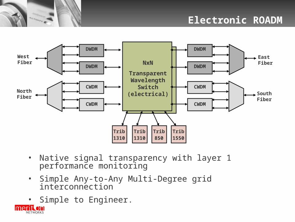
Electronic ROADM
NxN
TransparentWavelength
Switch(electrical)
Trib1310
Trib1310
Trib850
Trib1550
DWDM
WestFiber
EastFiber
DWDM
DWDM
DWDM
NorthFiber
CWDM
CWDM
SouthFiber
CWDM
CWDM
• Native signal transparency with layer 1 performance monitoring
• Simple Any-to-Any Multi-Degree grid interconnection
• Simple to Engineer.

Optical ROADM – Wave-blocker
Splitter Wave-blocker
Drop Filter
Add Filter
Coupler
• Drop and Add Filters must be tuneable for maximum flexibility.
• Hitless filter tuning is a problem.
• Many discrete components so expensive
• High insertion loss – Limits DCM – Limits reach between nodes for fully transparent networks.

Optical ROADM – Wavelength Selective Switch (WSS)
WavelengthSelective Switch
Add
Coupler
DropChannels
OptionalExpansionPort
• Fewer discrete optical components
• Fully flexible colourless add/drop
• Lower insertion loss
• Limited number of drop ports – Use expansion port !

Comparison- Wavelength Switching
Functionality Electronic ROADM Optical ROADM
Transparency(bit rate and protocol)
Yes- wide range of signals
Yes
Low Latency Yes Yes
Single wavelength granularity(I.e. no wavelength stranding)
Yes Yes
Mesh Support (multi-degree) Yes Yes- Blocking issues
Wavelength Translation Yes No
Grid Conversion(e.g. CWDM to DWDM)
Yes No
Protocol Performance Monitoring
Easy Optical power only
Wavelength Protection & Hitless Maintenance
Easy Ring – Easy
Mesh – More difficult

Implementing ROADM Interfaces
Optical and Electronic ROADM complement each other.
Trib1310
DWDMNxN
TransparentWavelength
Switch(electrical)
WestFiber
EastFiber
CWDMWest
Trib1310
Trib850
Trib1550
CWDMEast
DWDM
CWDM
CWDM
DWDM
DWDM
CWDM
CWDM
Pass-through TrafficNorthFiber
DWDM
DWDM
DWDM
DWDM
SouthFiber
OpticalROADM
I/F
OpticalROADM
I/F

Multi-Degree ROADM Interfaces
First step towards full NxN photonic wavelength switch.
Optical Pass-through channelsNorthFiber
SouthFiberOptical
ROADMI/F
OpticalROADM
I/F
NorthWFiber
DWDM
NxN
TransparentWavelength
Switch(electrical)West
FiberEastFiberDWDM
DWDM
DWDM
OpticalROADM
I/F
SouthEFiberOptical
ROADMI/F
DWDMDWDM DWDM
DWDM

2.5Gbps - 2 DEGREE NODE
0
0.1
0.2
0.3
0.4
0.5
0.6
0.7
0.8
0.9
1 6 11 16 21 26 31 36
# PASSTHRU WAVELENGTHS
CO
ST
(A
U)
ELECTRICAL OPTICAL
~17
Cost Comparison – 2.5G Traffic

10Gbps - 2 DEGREE NODE
0
0.5
1
1.5
2
2.5
1 6 11 16 21 26 31 36
# PASSTHRU WAVELENGTHS
CO
ST
(A
U)
ELECTRICAL OPTICAL
~6
Cost Comparison – 10G Traffic

Wavelength Switching - Cost sweet spots
4 8 12 16 20 24 28 32Pass-through Channels
Optical ROADM
ElectronicROADM
Optical ROADM
ElectronicROADM
10G
2.5G
ChannelRate
Note:For 2-degree metro ring applications. Also applies to 4-degree mesh architecture

The Future of 40G/100G

40Gbps/100Gbps
40Gbps 40Gbps DWDM trials and demonstrations becoming more common.
Ability to overlay on existing 2.5/10G links – a key driver !
40Gbps router interfaces have been demonstrated.
Dispersion must be controlled within ± 62 ps/nm.
PMD is an issue. Cannot exceed 2ps (outage < 3min/year)
100Gbps Can 100Gbps be achieved over DWDM ?
Dispersion tolerance even tighter - ± 25 ps/nm.
PMD more of an issue. Cannot exceed 1ps (outage < 3min/year)

40Gbps Dispersion Tolerance 6x80kmx26dB - 32
• 100GHz spacing SPM, XPM and FWM effects included
Range of possible net dispersion
0
1
2
3
4
5
6
-600 -400 -200 0 200 400 600
Net Dispersion (ps/nm)
Pen
alty
(d
B)
40Gbps 10Gbps
Tunable Dispersion Compensation Required for 40Gbps.

100Gbps
Several published examples of single wavelength 100Gbps+ transmission.
Spectral width ~ 150 GHz for NRZ so won’t fit into a 100GHz spaced DWDM pass-band (~85GHz) !
Dispersion limit for NRZ is ± 25ps/nm.
If we use non-binary coding – Spectral width reduced to 75GHz – Just fits within 100Ghz spaced DWDM band.
Needs tight control of laser + filter wavelengths.
Using >1 bit per symbol coding technique such as duo-binary or QPSK improves tolerance to dispersion and PMD.
100Gbps is achievable. Needs sophisticated coding!

Polarization Mode Dispersion
Using 6x80kmx26dB with 6 EDFA and 6 DCM, the calculated average DGD (assuming fiber is post 1995) = 2.5 ps
The PMD tolerance (and expected outage) for various data rates is:
Rate pmd tolerance system outages/yr
2.5G 30ps insignificant pmd outages/yr
10G 7.6ps insignificant pmd outages/yr
40G(NRZ) 2ps ~ 3 minutes/year assuming FEC
100G(NRZ)0.9ps Requires PMD compensation
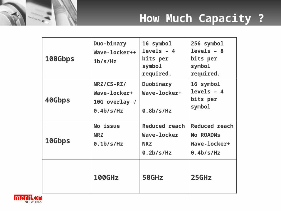
How Much Capacity ?
100Gbps
Duo-binary
Wave-locker++
1b/s/Hz
16 symbol levels – 4 bits per symbol required.
256 symbol levels – 8 bits per symbol required.
40Gbps
NRZ/CS-RZ/
Wave-locker+
10G overlay
0.4b/s/Hz
Duobinary
Wave-locker+
0.8b/s/Hz
16 symbol levels – 4 bits per symbol
10Gbps
No issue
NRZ
0.1b/s/Hz
Reduced reach
Wave-locker
NRZ
0.2b/s/Hz
Reduced reach
No ROADMs
Wave-locker+
0.4b/s/Hz
100GHz 50GHz 25GHz

Summary
On-Demand Light-path Control Enabled by:
Distributed, Intelligent Light-path Control (UCLP, GMPLS)
Electronic and Optical ROADM.
Widely Tunable Laser Sources.
40Gbps/100Gbps 40Gbps can be deployed over existing 10G infrastructure with
appropriate dispersion control + FEC.
100Gbps will a challenge requiring sophisticated coding schemes and components for PMD mitigation.

Thank You

Impact of Tighter Channel Spacing
Four Wave Mixing (FWM)
-30.00
-25.00
-20.00
-15.00
-10.00
-5.00
0.00
0 20 40 60 80 100 120
WAVELENGTH SPACING (GHz)
FW
M E
FF
ICIE
NC
Y (
dB
)
SMF-28 LEAF DSF
Increased FWM Impact – Reduced Reach.

Impact of Tighter Channel Spacing
Cross Phase Modulation distortion (XPM)
-20
-18
-16
-14
-12
-10
-8
-6
-4
-2
0
0 20 40 60 80 100 120
WAVELENGTH SPACING (GHz)
XP
M E
FF
ICE
NC
Y (
dB
)
SMF-28 LEAF DSF
Increased XPM Impact – Reduced Reach.