towards a general component model for web-based applications
TRANSCRIPT

Annals of Software Engineering 13, 35–69, 2002 2002 Kluwer Academic Publishers. Manufactured in The Netherlands.
Towards a General Component Model for Web-BasedApplications
COLIN ATKINSON, CHRISTIAN BUNSE and HANS-GERHARD GROß
Institute for Experimental Software Engineering, Sauerwiesen 6, D-67661 Kaiserlautern, Germany
THOMAS KÜHNEUniversität Kaiserslautern, AG Component Engineering, PO BOX 3049, D-67653 Kaiserslautern,Germany
Abstract. The cost effective development of web applications is perhaps one of the most challenging ar-eas of software engineering today. Not only are the problems to be solved, and the solution technologiesto be used, in web application development among the most rapidly changing in the software industry,but the business pressures of cost, quality and time-to-market are among the most extreme. Web appli-cation development therefore has potentially the most to gain from software reuse approaches that canoffer a greater return on development time than traditional approaches. However, simply combining ideasfrom these reuse paradigms and traditional web development technologies in ad-hoc ways will not resultin sustainable improvements. In this paper we describe a systematic way of combining the benefits ofcomponent-based development and model driven architectures, two important reuse approaches, to sup-port the cost effective development and maintenance of web applications. After first defining a suitablyabstract component-model, the paper explains how component architectures can be systematically and rig-orously modeled using UML. It then describes a powerful technique, known as stratification, for separatingthe various cross cutting aspects of a web application such that a suitable platform specific architecturecan be traceably generated. Finally, the paper introduces a technique for increasing the trustworthiness ofcomponents by giving them the capability to check their deployment environment at run-time.
1. Introduction
With the growing importance of the World Wide Web for almost all kinds of commercialactivities, software development organizations are facing increasing pressure to maketheir software applications web-compatible. However, systematically migrating applica-tions to the web is no easy task [Robertson 1997]. The web domain is not only clutteredwith more technologies and platforms than almost any other area of software develop-ment, but is also the domain in which the rate of technology evolution is the most rapid.The technological and business pressures of application development are thus more ex-treme in the web domain than in almost any other area of software engineering.
Cost effectively developing web applications therefore necessitates the systematicexploitation of software reuse approaches that can offer a greater return on investmentthan traditional development approaches. This involves the integration of establishedInternet implementation technologies with leading reuse paradigms such as:

36 ATKINSON ET AL.
1. Component-based development [Szyperski 1999]
2. Model driven architectures [OMG 2001].
3. Product-line engineering [Weiss and Lai 1999].
Combining these in superficial, ad-hoc ways will not provide the desired long-term benefits, however. Ad-hoc techniques may be acceptable for solving immediateproblems, but rarely improve an enterprise’s long-term strategic software developmentcapabilities. To achieve this, a clean and logically coherent development approach isneeded. The goal of this paper is to lay the foundation for such a development model forweb-based applications, and to explain how it can be used to develop web applications inconjunction with established implementation technologies. Since the component para-digm lies at the heart of the approach, the emphasis in the paper is on describing the core“component model.” However, the paper also describes practical techniques for support-ing model driven architectures and improving the trustworthiness of components.
The approach draws upon ideas from three main sources: the KobrA method [At-kinson et al. 2001], architecture stratification [Atkinson and Kühne 2002], and built-incontract testing [Component+ 2001]. The KobrA method provides the basis for theunderlying component model and the strategy for UML-based component modeling. Italso supports component-based product line engineering, but this is not discussed furtherin this paper.
Architecture stratification, developed at the University of Kaiserslautern [Atkinsonand Kühne 2002], builds upon the core component model and UML-based modeling ap-proaches to provide a flexible way of separating the description of distinct cross-cuttingaspects of a system. This is important in every application domain, but particularly so forweb-based applications which are inherently distributed, and thus embody the multiplerealization layers that are characteristic of distributed systems. Web-based applicationsalso tend to be more heterogeneous than in most other domains, and thus have a greaterneed for distinct levels of abstraction and interface wrapping concepts. Describing everydetail of a system’s realization directly at the lowest level of abstraction usually intro-duces too many small-grained components, and makes it difficult for certain stakeholdersto understand the aspects of the system they are interested in. Stratification allows dis-tinct cross cutting concerns to be described independently at different architectural levelsof abstraction.
The final contribution of the paper is to extend the core component model with atechnique for increasing the trustworthiness of components by giving them the capabil-ity to check their deployment environment at run-time. This is an essential aspect ofcomponent-based development, whose central tenet is that applications are assembledfrom independently developed (third-party) components which may not necessarily bedeveloped together. Thus, there is no guarantee that a component will work in a particu-lar deployment situation even if it has been thoroughly tested during development. Builtin contract testing, developed within the European Community funded COMPONENT+project, addresses this problem by providing components with built-in test (BIT) soft-ware to check that they have been deployed in a suitable environment. BIT-components

A COMPONENT MODEL FOR WEB-BASED APPLICATIONS 37
are particularly well suited to web applications in which dynamic reconfiguration is fre-quent and/or the overhead of built-in tests is relatively small.
To provide a coherent and uniform example of the approach we use a single exam-ple throughout the paper – a Simple International Banking (SIB) system. This systemsimply allows users to open and use bank accounts which may be denominated in variouscurrencies. In other words, customers can open accounts, deposit or withdraw moneyinto these accounts (in one of the currencies support by the bank) and can request forcurrency conversion calculations to be performed. The range of currencies that are sup-ported depends on the set of exchange rates that have been entered into the bank. Bankclerks can enter up-to date exchanges rates for any currency at any time.
The remainder of the paper is structured as follows. Section 2 describes the abstractcomponent model upon which all other aspects of the approach are based. Section 3then describes how systems of components based on this model can be represented ina platform independent (i.e., UML-based) way to generate a component-based, modeldriven architecture. Section 4 builds upon this approach by introducing a technique forseparating the various cross cutting aspects of a web application so that different plat-form specific models can be traceably generated from the platform independent (modeldriven) architecture. The application of this approach to several well know web-orientedarchitectural patterns is also discussed. Section 5 explains how the basic componentmodel introduced in section 2 can be extended to support built-in contract testing, andthrough this, how the trustworthiness of components in particular deployment situationscan be improved. Finally, section 6 describes how the ideas presented relate to existingwork, and section 7 concludes with some final remarks.
2. The core component model
The purpose of a component model is to define the underlying conceptual characteristicsof the components used within a development approach without worrying about howthese characteristics are represented. Generally speaking, there are two basic issueswhich a component model must address: the characteristics of individual components,and the characteristics of the relationships between them.
2.1. Components
The most fundamental question to be addressed by any component model is “what isa component?” To answer this in a concrete way it is essential to consider both thedevelopment-time and run-time aspects of the software life cycle. This is becausethe concept “component” can have both a run-time and a development time incarna-tion [Szyperski 1999]. Different component technologies handle these distinct incar-nations or facets in different ways. Some, like COM [Tapadiya 2000], ignore thedevelopment-time facet, and view a component as merely a run-time entity. Others,like the UML [OMG 2000], ignore the run-time facet and view a component as merelya development-time artifact. Yet others, like Enterprise Java Beans (EJB) [Matena and
38 ATKINSON ET AL.
Stearns 2001], use the term component (or rather its synonym “bean”) to refer to both. Inother words, sometimes the word “bean” means a component type (development-time)while at others it means a component instance (run-time). To minimize the potential forconfusion in our component model we follow the UML approach and expressly use theterm “component instance” to refer to the run-time incarnations of components. Thisleaves the term “component” to unambiguously refer to the development-time incarna-tion of components, that is, an instantiatable type.
Another critical choice to be made with respect to components is whether they areto be thought of as entities that make services available by virtue of their contents, or asentities that make capabilities available by their own behavioral features. This differencecan be characterized as the distinction between a module (i.e., container) and a class. Aswith the previous choice, there are three basic approaches. Some component models,such as the UML and JavaBeans, take the module (container) approach, and view com-ponents as having behavior solely by virtue of the other entities that they contain (e.g.,operations, objects, etc.), while others, such as COM and CORBA, view components ashaving behavioral capabilities in their own right.
We take the middle position, and regard components as integrating both view-points. In other words, a component is viewed as a hybrid fusion of the class and moduleconcepts. A component has module-like properties (i.e., package-like properties in theUML) in that it represents a namespace and has contents, but also has class-like prop-erties in that it possesses operations and attributes that provide services to other compo-nents. In this sense a component is more like a UML subsystem than a UML component.
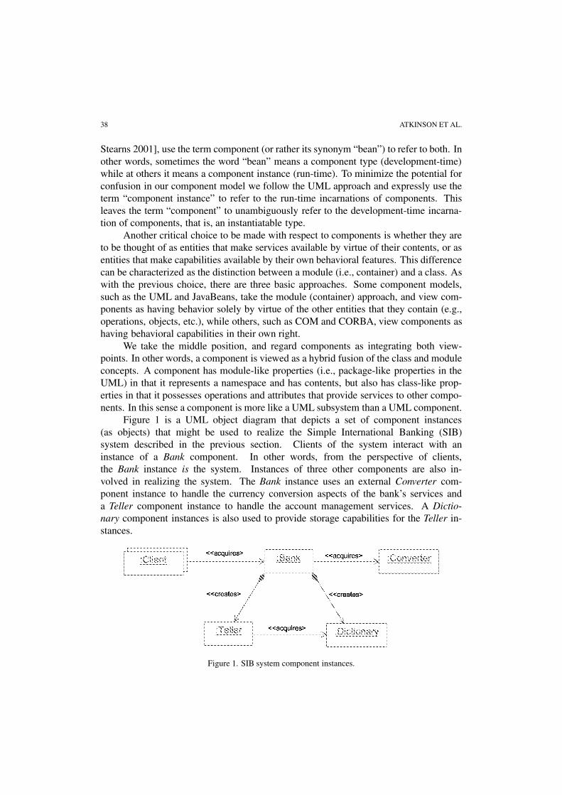
Figure 1 is a UML object diagram that depicts a set of component instances(as objects) that might be used to realize the Simple International Banking (SIB)system described in the previous section. Clients of the system interact with aninstance of a Bank component. In other words, from the perspective of clients,the Bank instance is the system. Instances of three other components are also in-volved in realizing the system. The Bank instance uses an external Converter com-ponent instance to handle the currency conversion aspects of the bank’s services anda Teller component instance to handle the account management services. A Dictio-nary component instances is also used to provide storage capabilities for the Teller in-stances.
Figure 1. SIB system component instances.

A COMPONENT MODEL FOR WEB-BASED APPLICATIONS 39
Figure 2. SIB system components.
Figure 2 is a UML diagram showing the development time component types (i.e.,components) from which the component instances in figure 1 are instantiated. Thisdiagram emphasizes the package facet of components, while figure 1 indirectly reflectsthe class facet by showing component instances. The explicit representation of the classfacet of a component will be described in section 3.
Although component instances can be thought of as objects, and components canbe thought of as classes, these are not the only objects and classes used in a system.Other “regular” classes and objects also play an important role in system implementa-tion. Generally speaking, components represent the behavior rich, or structural unitsof a system that encapsulate most of the complex functionality. This means that thereare usually just a few instances of them in a system (in fact, they are often singletons).Simple classes, in contrast, represent information-conveying units of a system and onlyencapsulate limited functionality directly concerned with accessing and setting this data.This means that there are often many instances of these classes in a system.
In the context of web applications, concepts from the relevant web technologiesare needed to characterize and classify the simple classes (i.e., data structures) usedwithin an application. For example, data structures exchanged between components(e.g., browsers and web servers) can be classified as HTML documents or CGI scriptsaccording to the particular technology in use.
The most important standard in this regard is the Document Object Model (DOM),defined by the World Wide Web Consortium. The DOM provides a platform-neutraldefinition of browsers and the documents that they manipulate (e.g., HMTL, XML, . . . ,etc.). The exact hierarchy of classes defined in the DOM is illustrated in figure 3. Many,

40 ATKINSON ET AL.
Figure 3. Document object model class hierarchy.
but not all, of the concepts used in the realization of web applications are included inthis hierarchy in a way that is compatible with most leading web implementation tech-nologies.
2.2. Component relationships
The second fundamental question that a component model must address is “how arecomponents put together to create useful systems?” Again, the distinction between therun-time and development time facets of a system is critical in providing a concreteanswer to this question.
At run-time, two fundamental kinds of inter-component relationships are of impor-tance:
1. Composition.
2. Clientship.
Composition is the idea that one component is a private part of another component, andis tightly tied to it with respect to both its identity and lifetime. It actually captures themost basic idea of something being a component.1 Nevertheless, composition is not themost fundamental relationship between components. An even more fundamental rela-tionship is the clientship relationship, which arises from the interaction of componentsvia operation (method) invocations. For any given interaction, the invoker of an oper-ation (method) is the client, while the owner of the operation is the server. Based onthe long established semantics of object-oriented languages, the clientship relationshipis asymmetric, with the client knowing the identity of its servers, but servers not usuallyknowing the identity of their clients.
The composition and clientship relationships have very different properties froma structural point of view. In general, composition traces out a tree of objects while
1 “Component” is really a relative concept rather than an absolute concept. Something is a componentbecause it is a part of something else, not because it has a particular form.

A COMPONENT MODEL FOR WEB-BASED APPLICATIONS 41
clientship traces out an arbitrary graph. It is also important to realize that compositionimplies clientship, since a composite must be a client of its parts in order to create them.The composition relationships therefore form a subset of the clientship relationships.
Figure 1 depicts the clientship relationships between the component instances inthe SIB system, and explicitly distinguishes those that represent composition from thosethat do not. The standard UML notation for composition (black diamond) is used toindicate that the Teller and Dictionary instances are parts of the Bank instance (i.e., aBank instance is composed of a Teller instance and a Dictionary instance). This meansthat they are created by the Bank instance for its own private use. The Converter instanceis not a part of the Bank instance, however. On the contrary, a Bank instance needs to“acquire” access to a Converter instance at run time. The Converter instance is still aserver of the Bank instance, but is not a part of it.
At development-time there are also two important relationships to be considered:
1. Ownership.
2. Containment.
As mentioned above, components have the properties of both modules and classes. Own-ership is the UML term for the relationship between a module (package in the UML) andthe elements nested within in it. In other words, ownership is used to convey the idea thatone thing is contained by another in terms of scope. In the UML, and most languagesthat support modules, the nesting of modules (and thus the ownership relationship) cre-ates a tree. Furthermore, in conjunction with certain visibility modifiers (e.g., public,private, protected) the nesting of modules controls the visibility that model elements canhave of one another.
In the UML, the term “ownership relationship” could easily have been replacedby the term “containment relationship,” because this is the basic idea that ownershipcaptures. In fact, although the UML attaches no formal semantics to the term “con-tainment,” much of the text used to describe the nesting of packages in the UML docu-mentation [OMG 2000] uses this term or its derivatives. In our component model, theterm containment is used to identify a particular form of ownership. This is a form ofownership in which the tree of components is reconciled with the run-time relationshipsbetween components (i.e., the composition and clientship relationships).
What does this mean? As mentioned above, the hierarchy of components repre-sented by the ownership hierarchy defines the visibility that components and their in-stances can have of one another. Clearly, it is possible to define ownership hierarchiesin which the components do not have the visibilities needed to support the run-timeclientship relationships. A containment hierarchy is defined to be an ownership hierar-chy in which the visibilities required for the run-time clientship are satisfied.
One easy way to achieve this is to create an ownership tree with only two levels: aroot, and all other components as children of this root. This would certainly provide allthe visibility needed for clientship, because every component would be able to see everyother component. However, in such an approach many of the advantages of compositionand information hiding would be lost. A containment tree should therefore provide the

42 ATKINSON ET AL.
maximum amount of composition compatible with the visibility needed for clientship.In other words, a containment tree should have the minimum number of clientship rela-tionships at development time needed to satisfy the clientship relationships at run-time.
This can be achieved in a systematic way by taking the run-time composition treeas the starting point for the organization of the components in the containment tree,and then making the minimum number of changes needed to satisfy run-time clientship.A change to the tree is affected by moving a component to a higher location in the tree sothat it can be seen by more components. If no single composition tree exists, or multiplecomposition trees exist, the creation tree (which resembles the single composition tree ifone exists) is used as the starting point. An ownership tree whose structure is organizedin this manner is said to be “aligned” with the run-time structure of the system, and theownership relationships are viewed as being containment relationships.
In general, therefore, the following relationships hold between run-time and devel-opment time inter-component relationships
composition ⇒ clientship (if X is a part of Y, Y is a client of X),
containment ⇒ ownership (if X contains Y, X owns Y.)
Figure 2 explicitly illustrates the containment relationships between the compo-nents. In this case, because of the correlation between the run-time clientship and com-position relationships, the shape of the development time containment tree can be exactlyaligned with the run-time composition tree. Thus, the Teller and Dictionary componentsare contained by Bank. In order to provide a single root for the containment tree we adda package called BankContext. The exact role of this package will be explained in thefollowing section.
3. Model-based representation of components
The component model defined in the previous section is an abstract one, since it does notprescribe how the characteristics of individual components and their relationships shouldbe described. The abstract component properties and relationships defined in the modelcan be represented in many ways, such as the Java code of Enterprise Java Beans orthe IDL specification of a CORBA application. The point of the MDA approach, how-ever, is to avoid premature representation of components in a specific-implementationtechnology, but rather to capture their essential features in a platform independent wayin terms of UML models. This involves more than just using UML component dia-grams to document the static interfaces and interconnections of component instances.Since components can be complex behavioural abstractions offering complex servicesand possessing complex dependencies, developing a component-based, model drivenarchitecture involves the modelling of all the complex and subtle properties of compo-nents and how they are interconnected at both run-time and development time. A modeldriven approach to component based development should thus use many UML diagramsproviding multiple, interconnected views of a system and its components.

A COMPONENT MODEL FOR WEB-BASED APPLICATIONS 43
The core component model described in the previous section can be representeddirectly in a platform specific technology, or can first be represented in a platform in-dependent way in terms of UML models. The former is referred to as the lightweightapproach, while the latter is referred to as the heavyweight approach. The advantageof the former is that it leads more directly to an executable incarnation of the compo-nents, avoiding the overhead of UML models. The advantage of the latter is that oncethe model driven architecture has been established, different executable incarnations canbe generated from it in a more cost effective way.
3.1. Modelling components
Our strategy for the model-based representation of components is illustrated in figure 4.The figure shows how a single, logical component is described by a suite of carefullyinter-related UML diagrams. All the components in a system are described in the samebasic way, each with its own suite of UML diagrams. Thus, UML diagrams are deployedin a “localized” way to describe properties from the perspective of one and only one com-ponent. This “principle of locality,” as it is known, is an important distinguishing featureof the method, and is applied to all artefacts developed during software development,such as requirements specification, test cases, etc. as well as to UML diagrams. As canbe seen from figure 4, the description of a component is split into two main parts: thespecification, which describes the externally visible properties of the component, andthe realization, which describes how the component works.
Since the specification diagrams collectively define the externally visible propertiesof the component, in a general sense they can be viewed as representing its interface. Thestructural diagram describes the types which the component manipulates, the roles withwhich it interacts and the list of services and attributes which it exports. It also explicitlydescribes the class facet of the component. The functional model provides a declarativedescription of each of the services or operations supported by the component in terms ofpre and post conditions. Finally, the behavioural model describes the externally visible(i.e., logical) states exhibited by the component.
Figure 4. Documenting components using UML diagrams.

44 ATKINSON ET AL.
The realization models collectively define how the component realizes its speci-fications in terms of interactions with other components and objects. This can includeexternally acquired server components, or subcomponents which the component cre-ates and manages itself. The realization diagrams collectively describe the architectureand/or design of the component. The structural diagram is a refinement of the specifica-tion structural diagram which includes the additional types and roles needed to realizethe component. The interaction diagrams document how each operation of the compo-nent is realized in terms of interactions with other components and objects. Finally, theactivity diagrams documents the algorithm by which each operation is realized.
A complete model driven architecture is created by hierarchically organizing themodels of the individual components in the system. In the following subsections weillustrate this modelling approach in terms of the SIB system example introduced in theprevious section.
3.2. The context realization
From the perspective of the outside world the system looks like a single component,interacting with other components or actors to achieve a common goal. To support a re-cursive and uniform development approach this community of interacting components,at the context level, is modelled in the same way as a community of components withina component – as a realization. In other words, the environment of a system is modelledusing the same set of diagrams as a component realization, and is thus referred to asthe “context realization.” In the SIB system example, the context realization models arestored within the BankContext package illustrated in figure 2. Like the internal realiza-tion of a single component, the context realization consists of three separate models, asillustrated in figure 4.
3.2.1. Context realization structural modelThe context realization structural model describes the actors and components in the en-vironment of the system of interest, the nature of the relationships between them, andthe form of the information entities that they exchange.
The structural model for the context of the Bank (figure 5) shows that the Banksystem (viewed as a component) interacts with a Converter instance and one ore moreClient instances. The «acquires» stereotype indicates that clients acquire access
Figure 5. Bank context structural model.

A COMPONENT MODEL FOR WEB-BASED APPLICATIONS 45
to the Bank dynamically, and that Bank handles Account objects which are owned byCustomers.
3.2.2. Context realization activity modelThe activity model describes the processes affecting the system component in terms ofa hierarchy of activities at various levels of granularity. The activities near the top ofthe hierarchy correspond to high-level business processes, while those at the leaves ofthe hierarchy correspond to system operations. Activities which capture self-containedunits of functionality can be viewed as use cases, and may be depicted as such in a usecase diagram. Activity diagrams are the main kind of UML diagram used in the activitymodel. An activity diagram illustrates how an activity is realized in terms of lower-levelactivities.
3.2.3. Context realization interaction modelThe interaction model shows similar information to the activity model but in terms ofinteractions between components and objects rather than control flow between activities.Each individual interaction diagram describes the same algorithm as the correspondingactivity diagram but from a different perspective. The information is similar to thatprovided by the sequence diagrams representing use case instances, and in fact, UMLsequence diagrams are a valid form of interaction diagram.
Figure 6 illustrates the interaction diagram for the interactions involved in showingaccounts.
3.3. Bank
The Bank is the root component of the containment tree and represents the system to bedeveloped. From the perspective of users of the Bank, this component provides all theavailable functionality. As explained previously, in general a component has a specifi-cation and a realization. The specification describes the externally visible properties ofthe component, and the realization describes the private design of the component: thatis, how it works.
Figure 6. Showing account interaction diagram.

46 ATKINSON ET AL.
Figure 7. Bank specification structural model.
3.3.1. Bank specificationThe specification of a component is composed of several interrelated artefacts, three ofwhich are of primary importance: the structural model, the functional model and thebehavioural model.
3.3.1.1. Bank specification structural model The structural model describes the entitieswith which the component interacts (e.g., external actors or other components) and thedata structures which it manipulates or access. Only the externally visible structuralproperties of the component are documented in the structural model.
As illustrated in figure 7, a structural model is normally a class diagram, althoughobject diagrams can also be provided in addition if necessary. Figure 8 shows the speci-fication structural model of the Bank component. The class representing the Bank com-ponent in this diagram is thus labelled with the stereotype «subject» to indicate thatit is the focus of the diagram. Other components which the component needs to acquire(i.e., Converter) are also illustrated in the diagram, and are labelled with the stereotype«component» accordingly.
Among other things this diagram shows the operations supported by the subjectcomponent, and the operations of the acquired components that the subject uses. In thisrespect, acquired components represent roles from the point of view of the subject.
3.3.1.2. Bank specification functional model A component’s functional model docu-ments the externally visible properties of a component’s operations. It does this in theform of Fusion [Coleman et al. 1994] style operation specifications which define the preand post conditions on each operation. There is one operation specification for each op-eration. The “assumes” clause defines the precondition and the result clause defines thepost condition. Other clauses summarize information from the “assumes” and “result”clauses, such as the information received and or manipulated, or the rules for calculatingthe result.
An important feature of operation specifications is that they must only be declar-ative. This means that they must not describe how the result is attained procedurally,just what the result is. Also, they must only refer to information defined in the compo-

A COMPONENT MODEL FOR WEB-BASED APPLICATIONS 47
Figure 8. Bank.withdraw() operation specification.
nent’s other specification models. This is one example of a consistency rule between themodels of a component.
Figure 8 shows the specification for Bank’s withdraw() operation. In general, anoperation specification is needed for each operation of the component. The main con-straint on the construction of operation specifications is that the pre and post conditions(assumes and result clauses) may only refer to classes, attributes and relationships de-fined in the component’s specification class diagram. Any suitable textual notation canbe used, including the Object Constraint Language (OCL), defined as part of the UMLstandard [OMG 2000].
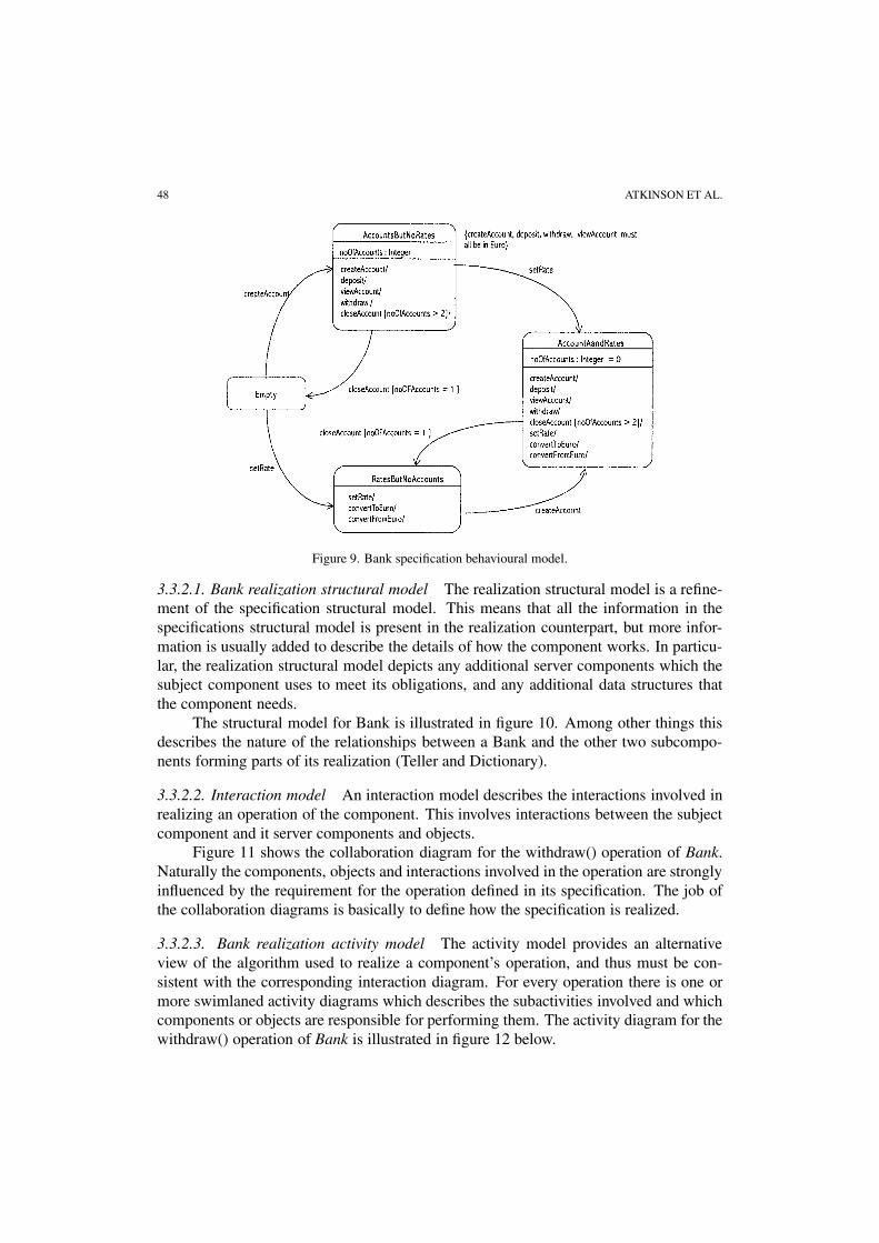
3.3.1.3. Bank specification behavioural model The behavioural model describes theexternally visible states of the component, the events that trigger transitions betweenthese states and the operations that are invoked as a result. Figure 9 shows the behav-ioural model of the Bank component.
3.3.2. Bank realizationThe realization of a component represents its private design. It documents how thecomponent realizes the requirements laid down in its specification. As explained in sec-tion 3.2, a realization consists of three primary models: a structural model, an interactionmodel and an activity model. Examples of each are given below.
48 ATKINSON ET AL.
Figure 9. Bank specification behavioural model.
3.3.2.1. Bank realization structural model The realization structural model is a refine-ment of the specification structural model. This means that all the information in thespecifications structural model is present in the realization counterpart, but more infor-mation is usually added to describe the details of how the component works. In particu-lar, the realization structural model depicts any additional server components which thesubject component uses to meet its obligations, and any additional data structures thatthe component needs.
The structural model for Bank is illustrated in figure 10. Among other things thisdescribes the nature of the relationships between a Bank and the other two subcompo-nents forming parts of its realization (Teller and Dictionary).
3.3.2.2. Interaction model An interaction model describes the interactions involved inrealizing an operation of the component. This involves interactions between the subjectcomponent and it server components and objects.
Figure 11 shows the collaboration diagram for the withdraw() operation of Bank.Naturally the components, objects and interactions involved in the operation are stronglyinfluenced by the requirement for the operation defined in its specification. The job ofthe collaboration diagrams is basically to define how the specification is realized.
3.3.2.3. Bank realization activity model The activity model provides an alternativeview of the algorithm used to realize a component’s operation, and thus must be con-sistent with the corresponding interaction diagram. For every operation there is one ormore swimlaned activity diagrams which describes the subactivities involved and whichcomponents or objects are responsible for performing them. The activity diagram for thewithdraw() operation of Bank is illustrated in figure 12 below.

A COMPONENT MODEL FOR WEB-BASED APPLICATIONS 49
Figure 10. Bank realization structural model.
Figure 11. Bank.withdraw() collaboration diagram.
3.4. Component containment trees
The realization of a component, such as Bank, describes how it interacts with instancesof other components to realize its obligations. Sometimes these components may alreadybe defined (i.e., the types), but often a component may need a new type of componentfor its realization. Such a component could then be viewed as a subcomponent, andwould be described in exactly the same way, using the same general suite of UML di-agrams. When applied recursively this approach will lead to a tree shaped organization

50 ATKINSON ET AL.
Figure 12. Bank.withdraw() activity diagram.
of components, with strict consistency rules between the models describing componentsat different levels (i.e., between the models for a component and its subcomponents). Inthis way, a complete component-based architecture of the system can be generated interms of inter-related UML diagrams.
4. Stratification
Capturing the essential characteristics of components in a platform independent way isthe starting point for a model-driven approach to development, but it is not the wholesolution. In addition, an approach is needed for systematically transforming platform in-dependent models (PIMs) into platform specific models (PSMs). Although this mappingcan be automated to some extent, many critical decisions must still be made by humansoftware engineers. For example, although several models were shown in the previoussection, none contained any information related to web technologies. A natural ques-tion, therefore, is where information about specific web-oriented platforms is containedand how it is presented. To handle this problem in a systematic way we introduce theconcept of architecture stratification.
4.1. Which architecture is THE architecture?
The context realization class diagram illustrated in figure 5 provides an overall view ofthe structural architecture of the system from a logical point of view. It defines the natureof the components and agents involved in the system and the data structures that theyexchange, but all independently of a specific implementation approach. In the followingwe will consider a number of alternative views of this structural architecture.
Figure 13 provides an alternative version of the context realization class diagramfor the SIB example with two important differences. First, Account is explicitly defined

A COMPONENT MODEL FOR WEB-BASED APPLICATIONS 51
Figure 13. HTTP-based SIB context realization.
Figure 14. HTTP-oriented interaction diagram for showing accounts.
Figure 15. HTTP-oriented Bank specification class diagram.
to be a subclass of HTMLDocument, and the association between Client and Bank isadorned with the «HTTP» stereotype, to indicate that these interact via the http protocol.This still provides a relatively high level view of the architecture, but one that containsimportant information with regard to the realization strategy.
The choice of HTTP for the communication protocol between clients and the bank,and of HTML to represent accounts has ramifications on many of the other diagrams aswell. For example, figure 14 shows an alternative version of the interaction diagram forthe showing account use case. This is similar to that shown in figure 6, but now themethod sent to Bank is an HTTP request rather than a logical operation.
Not surprisingly, regarding Bank as an HTTP server has a major effect on its in-terface. Figure 15 shows how the Bank’s specification class diagram might look if itsservices were defined to support the HTTP protocol. Basically it has only one methodthat is capable of handling requests for any kind of HTML document.

52 ATKINSON ET AL.
Figure 16. IIOP-oriented SIB context realization class diagram.
Figure 17. ORB-oriented interaction diagram for showing accounts.
Of course, HTTP is not the only interaction protocol in common use within webapplications. Another commonly used approach is to view the client and server as dis-tributed objects and to use ORBs and the related IIOP protocol to communicate betweenthem. Figure 16 shows an alternative context realization class diagram for the SIB sys-tem corresponding to this scenario. In this version, ORB components are explicitly in-serted between Client and Bank, with an association indicating that they communicatebetween each other using IIOP. This is an equally valid architecture for the system.
Finally, figure 17 shows how the interaction diagram for the showing account usecase might look with an ORB based architecture.
The immediate question that arises is which of these viewpoints is the correct orthe best one. The answer is that they are all correct – each provides a valid view of thearchitecture of the system but from a different viewpoint. If one were forced to selectjust one architecture the most detailed architecture would probably be the best choice.This is the assumption that is usually used. In other words, when developers talk aboutTHE architecture they usually mean the most detailed one.
However, to support an MDA approach to software development it is important toaccommodate more than just this most detailed architecture, since the goal, by defini-tion is to avoid too much dependency on specific implementation platforms. This is thepurpose of the stratification concept. Stratification offers a way of stating requirementsin high-level views and turning them into concrete realizations in lower-level views. Itmakes all the important architectural views explicit, and relates them together in a sys-tematic and rigorous fashion. The basic premise underlying the concept of stratificationis that all levels of abstraction are relevant for a complete representation of a system’s

A COMPONENT MODEL FOR WEB-BASED APPLICATIONS 53
Figure 18. Interaction refinement.
architecture. Thus, using stratification, BOTH the high-level architecture and the lowlevel architecture discussed above would be combined into a single picture of the sys-tem.
4.1.1. Interaction refinementThe key to stratification is to reify and explicitly model the connectors or relationshipsbetween components. Most component and architecture description languages includethe concept of “connectors” to capture the interaction protocols through which compo-nents, or architectural units, can be connected together [Bass et al. 1998]. Ideally theseconnectors should be first class citizens of a description language, amenable to the sameset of manipulations as components themselves. Introducing the notion of abstractionlevels (i.e., strata) enables connector semantics to be understood in terms of lower levelcomponents.
Figure 18 shows how a high level interaction between X and Y is realised in termsof additional interactions and components at a lower level of abstraction. In other words,the interaction between X and Y is reified into components (A and B) and interactionswhich reside one stratum lower in the hierarchy. Understanding connectors (or relation-ships) as collections of components in lower architectural strata provides a clean modelfor their access and manipulation.
The different views of the interaction between X and Y represented by the upperand lower levels of figure 18 are often referred to as the logical and physical views,respectively. Stratification can be thought of as a systematic way of handling distinctlogical and physical views at various levels of abstraction.
In general, a complete stratified architecture is comprised of multiple strata as il-lustrated in figure 19. Each stratum represents a refinement of the stratum above, andthus typically contains additional components and interactions that explain how interac-tions in the higher strata are realized. In figure 19 the new components in a stratum arerepresented by white ovals, while those projected down from the stratum above are solid.The abstraction levels in a stratified architecture range from a high level, analysis-likedescription of the system down to the most detailed realization. The highest level willbe most useful for understanding the overall solution strategy. This stratum is populatedwith components and connector types that are key to understanding how the system is

54 ATKINSON ET AL.
Figure 19. Stratified architecture structure.
organized. In the lowest stratum one will find the usual complex network of objects usedto realize the low-level implementation details.
The key to effective stratification is the selection of appropriate sets of interactionswithin one stratum whose collective refinement elaborates on a well-defined aspect ofthe system’s realization. For instance, if in a refinement step starting from a businesslogic stratum one elaborates how remote interactions are realized, this will give rise toa “communication stratum.” The next level down could be devoted to dealing with per-sistence issues and so on. Depending on the application domain the same sequence oftypes of strata will be useful to structure a system’s architecture according to its emer-gent (often non-functional) properties. Therefore, stratifying the architecture of a webapplication will give rise to stratification levels that will be instrumental in developingother web applications.
4.2. Web-oriented architecture patterns
Although there are many different technologies and platforms that can be used to imple-ment web applications, the underlying concepts and features that they offer are basicallythe same. All web applications essentially consist of a client component, such as aHTML or XML browser, a web server that handles HTTP requests, and an applicationserver which is responsible for the business logic. Conallen [1999] defines three basicstrategies (or patterns) for combining these components together to create web applica-tions:
1. Thin Web Client.

A COMPONENT MODEL FOR WEB-BASED APPLICATIONS 55
2. Thick Web Client.
3. Web Delivery.
In this section we describe how the component-modeling approach described in sec-tion 3, combined with the stratification approach outline in section 4.1, provide a naturaland powerful way of capturing the essential characteristics of these patterns and the sim-ilarities and differences between them.
4.2.1. Thin Web ClientThe thin client architecture pattern is essentially a client/server configuration in which allapplication-oriented processing (i.e., business logic) is performed at the server side. Thisis the most appropriate architecture when client-side computing resources are minimal.
4.2.1.1. Logical stratum Applying the principles of stratification outlined in sec-tion 4.1, at the highest, logical level of abstraction a system adopting this pattern canbe characterized as a basic client/server architecture. The components making up suchan architecture are thus of the general from depicted in figure 20. WebApplication hasstereotype «context» since no actual component instances of this type exist at run-time. It serves as the container for the realization models describing the system levelproperties of a web application constructed according to this pattern.
At the logical level, the realization structural model for a WebApplication basedon the thin client pattern is relatively simple as illustrated in figure 21. This basicallyshows that multiple clients interact with a single server by exchanging data structuresand cookies.
4.2.1.2. Platform stratum The logical stratum shows the architecture of a web applica-tion independently of any particular realization approach. This is an essential prerequi-site for the MDA approach. The details of how the thin web client pattern is realized interms of specific web technologies is provided in terms of lower level stratum. For this,and the following pattern, only one additional stratum is considered, although in generalmore could be used. We refer to this additional stratum as the “platform” stratum to em-
Figure 20. Thin Web Client: Logical stratum components.

56 ATKINSON ET AL.
Figure 21. WebApplication realization structural model.
Figure 22. Thin Web Client: Platform stratum components.
phasize that it focuses on a specific realization technology. However, any other suitablename could be used.
Figure 22, a refinement of figure 20, shows the additional components visible at thelower level. It shows that an application of this pattern typically involves two subcompo-nents at the server side: a WebServer, which is responsible for fielding all requests fromthe client, and an ApplicationServer which is the primary engine for executing serverside business logic.
The components shown in figure 22 only illustrate the elements common to the ar-chitectural pattern. Typically the ApplicationServer will contain or access other business-oriented components such as databases etc, but this is application specific.
At the platform level, the realization structural model for a WebApplication (fig-ure 23) shows how the standard web technologies are used in the pattern. This indicatesthat the Client actually communicates with the server via the HTTP protocol (in fact, theServer plays the role of an HTML server) and the data structures exchanged between theclient and the server are actually HTML documents.

A COMPONENT MODEL FOR WEB-BASED APPLICATIONS 57
Figure 23. WebApplication realization structural model.
Figure 24. Server realization structural model.
Figure 24 elaborates on the details of how the server side works at the platformlevel. In particular it shows that information processed at the server side can be storedand manipulated in a number of different formats. A filter, or executable model, such asISAPI or NSAPI, translates these into HTML pages which the web server can send backto the client.

58 ATKINSON ET AL.
Figure 25. Thick Web Client: Platform stratum components.
4.2.2. Thick Web ClientAt the logical level, the thick web client pattern is exactly the same as the thin web clientpattern. It is essentially a client–server architecture, in which all data is stored on theserver side. The difference between the two therefore only shows up in the platformstratum.
4.2.2.1. Platform stratum At the platform level, the difference between the thick webclient and the thin web client patterns is that in the former the client can also executesome of the business logic. This pattern is therefore applicable when a sophisticateduser interface is needed. Figure 25 illustrates the form of the components making up aweb application at the platform level according to this architecture. The main differenceto figure 22 is the addition of the ClientEnhancement component.
Since it extends the client with the ability to execute business logic, the differencebetween the thick web client pattern and thin web client pattern is primarily manifest inthe client component’s realization models. The client’s realization structural model isillustrated in figure 26.
Figure 26 illustrates that a client in the thick web client pattern contains additionalenhancing elements, generically known as client enhancements, which interact with theweb server. Five main kinds of client extensions are available, PlugIns, ActiveX con-trols, Java applets, JavaBeans and client scripts, of which there are in turn two kinds,Java script and VB script. Figure 26 also shows that for client scripts to be able tocommunicate with the client it needs to be a DOM compliant browser.
4.2.3. Web Delivery patternAn important characteristic of the previous two patterns is that all communication be-tween the client and the server take place in the form of page requests, regardless ofthe level of enhancement at either end. Thus, interaction between client and server el-

A COMPONENT MODEL FOR WEB-BASED APPLICATIONS 59
Figure 26. Client realization structural model.
ements is essential stateless, with a new connection having to be established for everypage request.
The web delivery pattern addresses this problem by essentially making the applica-tion a fully distributed object system in which client side and server side business objectscan communicate in a direct and state based way. Web applications based on the webdelivery pattern are therefore essentially distributed object systems which include a webserver and browser as significant elements.
Because it assumes a particular configuration of components, this architecture isnot particularly suitable for general Internet-based applications. Its main strength it itsability to incorporate existing systems into web applications.
4.2.3.1. Logical stratum Since the web delivery pattern is essentially a general distrib-uted object architecture rather than a strict client/server architecture, it is distinguishablefrom the other patterns at the logical level. As illustrated in figure 27 the Browser andWebServer are now just two of an arbitrary number of business objects making up ageneral distributed object application.
Communication between these business objects takes place via a general remoteinvocation protocol, such as IIOP (from OMG), DCOM (from Microsoft) or RMI (fromSun), rather than via HTTP-based page requests. Interaction therefore takes place ac-cording to the object paradigm, including persistent states, rather than by stateless pagerequests.

60 ATKINSON ET AL.
Figure 27. Web Delivery: Logical stratum components.
5. Built in contract testing
One of the most important motivations for component-based software development isthat new applications can be created with significantly less effort than in traditional ap-proaches simply by assembling the appropriate prefabricated parts. In popular computerterminology this concept is captured by the “plug and play” metaphor. As soon as therelevant parts have been “plugged” together the user should be able to “play” with the re-sulting system. Contemporary component technologies are still some way from realizingthis vision, however.
With traditional development approaches, the bulk of the system integration workis performed in the development environment, giving engineers the opportunity toprecheck the compatibility of the various parts of the system, and to ensure that theoverall deployed application is working correctly. In contrast, the late integration im-plied by component assembly means there is often little opportunity to verify the correctoperation of applications before deployment time. Although component developers mayadopt rigorous test methodologies, with non-trivial software components it is impossibleto be certain that there are no residual defects in the code. In fact, even totally fault freecomponents may fail if they are connected to the wrong kind of components at deploy-ment time. Compilers and configuration tools can help to verify the syntactic compati-bility of interconnected components, but they cannot check that individual componentsare functioning correctly (i.e., that they are semantically correct). As a result, compo-nents that may have behaved correctly in the sanitary condition of the development-timetesting environment may not behave so well when deployed in a system where they haveto compete with other (third party) components for resources such as memory, processorcycles and peripherals.
Although the effort involved in plugging together components may be relativelysmall, therefore, the effort involved in verifying that the resulting assembly of systems

A COMPONENT MODEL FOR WEB-BASED APPLICATIONS 61
works as expected may be much greater than in traditional approaches. The reuse savingspromising by component-based development may thus be wiped out by the extra effortneeded at integration and deployment time to verify that a system is acceptable. Thisproblem is particularly acute in the web domain where the model of plugging togetherseparately developed components is the most common, and where systems are oftenreconfigured dynamically.
5.1. Built-in Test (BIT) components
As described in section 1, a component interacts with its environment (e.g., other com-ponents) at run-time by means of client/server interactions. One of the parties in aninteraction plays the role of a “client” which requests a service from another component,the “server.” In different interactions a given component can play either a server or aclient role, but in any particular interaction one of the parties involved plays the role ofa server and the other the role of a client.
Meyer [1997] characterizes the relationship between a client and a server as a for-mal agreement or a contract, expressing each party’s rights and obligations in the re-lationship. This means that individual components define their side of the contract aseither offering a service (the server in a client–server relationship) or requiring a service(the client in a client–server relationship).
When a fault free component is deployed in a new environment, there are basicallyonly two things that could go wrong during its execution: either the component itself isused incorrectly by others, or one or more components that it uses malfunction. Both ofthese scenarios can be characterized in terms of the client/server relationship: the formerimplies that one or more of a component’s clients behave incorrectly, while the latterimplies that one or more of a component’s servers behave inappropriately. Checkingthat these errors do not arise, therefore, can be characterized as checking that the contractbetween components is adhered to. Hence the name contract testing.
The two situations identified above are highlighted in the generic deployment sce-nario illustrated in figure 28. In terms of this diagram, there are two things that shouldideally be checked at run-time to ensure that a component’s contracts are adhered to:
1. The component (with the thickened border in figure 28) must verify that it receivesthe required support from its servers. This includes explicitly acquired serversand implicitly acquired servers (i.e., the run-time system). This scenario consid-ers contract verification from the viewpoint of the deployed component in ques-tion.
2. Clients of a deployed component must verify that the component implements theservices that it is contracted to provide correctly. In other words, clients of thecomponent must ensure that it meets its contract. This scenario considers con-tract verification from the viewpoint of the clients of the component in ques-tion.

62 ATKINSON ET AL.
Figure 28. Deployment of a component.
Figure 29. General form of BIT components.
Since components in general play the role of both clients and servers, the basic ideabehind built-in contract testing is to enhance components so that:
1. They can be tested by their clients.
2. They can test their own servers.
When all the components in a system have been enhanced in this way the semantic com-pliance of each component to its clientship contract can be automatically checked whena system is initially configured, and possibly later reconfigured. While most contem-porary component technologies enforce the syntactic conformance of a component toan interface, they do nothing to enforce the semantic conformance. This means that acomponent claiming to be a stack, for example, will be accepted as a stack so long asit exports methods with the required signatures. However, there is no guarantee that themethods do what they claim to do. Built in tests offer a feasible and practical approachfor validating the semantics of components.
Generally speaking, to support built in testing, a component acting as a server mustextend its regular functional interface with a testing interface, as shown in figure 29. Thiscontract testing interface consists of public methods for state setup and state validation.This enables controlled access to the internal states of a component for contract test-

A COMPONENT MODEL FOR WEB-BASED APPLICATIONS 63
ing while leaving the actual tests outside the component encapsulation boundary. Eachindividual client can thus apply its own test suite according to its intended use of thecomponent, that is according to its own profile for using the component.
In contrast, a component acting as a client must have a built-in tester for each ofthe server components that it wishes to test. This tester is a separate component whichincludes all the software needed to execute tests, including test cases. Before executingtest cases on the server’s normal interface the tester uses the server’s testing interfacefor state setup and state validation. The component tester contains test cases from theprovider of the component assuming that other providers will comply with the samespecification.
The degree of testing which a client component applies to a server may vary de-pending on the trustworthiness of the server. Thus, in general, a component may containseveral tester components for a given kinds of server component, each providing a differ-ent level of testing. These component must then provide a configuration interface whichallows the weight of the test to be determined at configuration time. This is referred toas the test interface.
5.2. Modeling BIT components
From the perspective of the component model outlined in section 2, BIT (Built in Test)components are normal components which can be modeled in the usual way. However,because the abstract state model of component is the starting point for designing its testinterface, the UML-based modeling approach outlined in section 3 is especially wellsuited for supporting the development of BIT components. In particular, the behaviouralmodel (represented as a UML state chart diagram) defines the set of states which needto be supported by the testing interface. In fact, the benefits are mutual, because theemphasis on test case development encouraged by an early consideration of built incontract testing serves to improve the consistency and completeness of the specificationmodels.
Figure 30 is a variation of figure 2 which illustrates the use of BIT components inthe SIB system example. The Dictionary instance acquired by Teller has now been madetestable, and the Dictionary instance now contains a DictionaryTester to test the Dictio-nary instance that it is given. Similarly the Converter instance acquired by Bank instanceis now a testable version, and the Bank instance therefore contains a ConverterTester totest the Converter instance it is given.
5.2.1. Bank realization structural modelThe realization structural model for Bank now has the form illustrated in figure 31. Thisis similar to the original model but with testable versions of Converter and Dictionarycomponents (i.e., TetsableConverter and TestableDictionary), respectively. The diagramalso includes the new component, ConverterTester, whose task is to test instances ofTestableConverter which Bank acquires from external sources. Of course, the Tellercomponent will also contain a tester component for testing TestableDictionary instances,

64 ATKINSON ET AL.
Figure 30. SIB system BIT component instances.
Figure 31. Bank realization structural model.
but this is part of Teller’s private realization, and thus is not visible at the level of Bank’srealization.
5.3. TestableConverter specification
The realization of a component describes built-in contract testing from the point of viewof a client. Bank is a client of TestableConverter, and thus needs to incorporate theappropriate tester component (i.e., ConverterTester) if it wants to ensure that componentinstances which claim to be TestableConverters are in fact TestableConverters. The

A COMPONENT MODEL FOR WEB-BASED APPLICATIONS 65
Figure 32. TestableConverter specification structural model.
specification of a BIT component such as TestableConverter describes built-in contracttesting features from the perspective of a server, including the externally visible statesof the component and the effects of the operations. The testing and test interfaces ofBIT components are described alongside the functional properties in the way describedin section 3.
5.3.1. Testable converter structural modelSince it is such a simple component, the specification structural model for TestableCon-verter is very simple (figure 32). In fact, it only consists of one class representing theTestableConverter itself. The important point to note is that in addition to the normalfunctional operations (convertToEuro(), convertFromEuro() and setRate()) the compo-nent also supports the two methods setToState() and isInState() which constitute thetesting interface. These two methods qualify TestableConverter as a BIT component,and enable its clients to subject its instances to contract tests at run time.
Since TestableConverter does not have any servers itself, it has no need for a testinterface. However, in general the test interface would also be modeled in a similar way.
5.3.2. TestableConverter specification behavioural modelThe behavioural model for TestableConverter describes the key externally visible statesand state transitions. Since a TestableConverter is essentially a data store (storing ex-change rates), its key states are essentially those of a container abstract data types asillustrated in figure 33. Three state are of importance in order to achieve full testability,Empty, which indicates that there are no exchange rates stored, Loaded, which indicatesthat there are some exchange rates stored but that there is still room for more, and Fullwhich indicates that there is no more room for any more exchange rates to be stored.
5.3.3. Functional modelAs with all components, the functional model of TestableConverter describes the logicaleffects of each of its operations, including the setToState() and isInState() operations.These must correlate with the states defined in the behavioural model, as illustrated infigure 34. This shows the specification of the setToState() operation.

66 ATKINSON ET AL.
Figure 33. TestableConverter behavioural model.
Figure 34. SetToState() operation specification.

A COMPONENT MODEL FOR WEB-BASED APPLICATIONS 67
6. Related work
As mentioned in section 1, the approach presented in this paper draws upon ideas fromthree main sources – The KobrA method [Atkinson et al. 2001], architecture stratifi-cation [Atkinson and Kühne 2002], and built-in contract testing [Component+ 2001].Naturally, these in turn have been inspired by other methods and techniques. In thissection we describe how the presented ideas relate to previous work.
The KobrA component model, which forms the basis for the core component modeldescribed in section 2, is based on the core concepts of component-based developmentas described for example by [Szyperski 1999] and [Bosch 2000]. The run-time seman-tics of components are similar to those in the ROOM approach [Selic et al. 1994],while the development time organization of artifacts is similar to the approach takenby HOOD [Robinson 1992]. The principle of organizing software development projectsaround the concept of recursive, stepwise refinement is found in many developmentmethods, but is most mature in the Cleanroom approach [Mill et al. 1987].
KobrA’s strategy for applying the UML, which forms the basis for the MDA ap-proach described in section 3, is strongly influenced by the Fusion method [Coleman etal. 1994] which in turn is influenced by the analysis approach of the OMT method [Rum-baugh et al. 1991]. Operation specifications, in particular, are very similar to the oper-ation schemata of Fusion. The approach also has similarities with other published ap-proaches for the UML-oriented modeling of components such as Catalysis [D’Souza andWills 1998] and UML Components [Cheesman and Daniels 2000]. The idea of usingclass diagrams to model the types crossing a component’s interfaces is shared with theseapproaches, as is the concept of using pre and post conditions to document the effectsof operations. KobrA is unique, however, in emphasizing the modeling of componentrealizations at all levels in a containment hierarchy.
The roots of the stratification concept originated within the NASA MISSIONproject [McKay and Atkinson 1995] to help manage the complexity of large, non-stopdistributed software systems such as the Space Station software. The concept has beenfurther refined within the AG Component Engineering [Atkinson et al. 1990] and [Atkin-son and Kühne 2002]. Stratification shares some of the basic aims of aspect-orientedprogramming [Kiczales et al. 1997] in that it supports the independent description ofcross cutting system concerns. However, it addresses the problem more from an archi-tectural perspective than a programming perspective.
The built-in contract testing approach described in the paper builds upon the ap-proach developed by Wang et al. [2000]. However, whereas their approach focused onself-testing, our approach focuses on the testing of servers. Thus, rather than performinga test on itself, in our approach a component tests the other components that it relieson for support, since only these can vary from environment to environment. Jézéquelet al. [2001] also advocate the building of test software into components, but their goalis to optimize the development time testing of components rather than to support in-situtesting at run-time.

68 ATKINSON ET AL.
7. Conclusion
The domain of web applications development potentially has the most to gain from thebenefits offered by component-based development, but also presents some of the biggestchallenges in applying it successfully. The cost savings, time savings and quality im-provements made possible by the component paradigm provide one of the best opportu-nities to relieve the extreme business pressures found in the web domain. However, bythemselves, the current generation of web technologies are not able to fully deliver thesebenefits. Directly describing components in a low-level implementation technology suchas EnterpriseJavaBeans or COM+ limits the possibilities for interoperability and porta-bility, and forces platform independent concepts to be represented in platform specificways. The lack of support for semantic interface checking also means that many of thesavings gained through component reuse and assembly are lost in the effort needed toverify the final system.
This paper has described a practical approach for addressing this problem by al-lowing component based development to be more readily exploited in the domain of webapplications. The approach consists of four main parts:
• a component model which captures the core concepts of component-based develop-ment in a suitably abstract way;
• a strategy for the model-based representation of components, facilitating the con-struction of a component-based, model driven architecture;
• a technique for traceably creating a platform-specific model of a component basedarchitecture in such a way that the major cross cutting concerns such as communica-tion, distribution, security etc., can be separated and described independently;
• an approach for increasing the trustworthiness of components by allowing them toverify the contract-compliance of their communication partners at run, thereby re-ducing the need for manual deployment time (e.g., acceptance) testing.
When used in combination we believe these approaches provide a clean and coher-ent strategy for exploiting the benefits of the two major reuse approaches addressed,component-based development and model driven architectures, in the development andmaintenance of web applications. Using techniques explained in the KobrA method [At-kinson et al. 2001], these approaches can also be enhanced to support a product lineengineering approach to development, but for space reason these could not be explainedin this paper. The ideas described in the paper are currently being elaborated in a varietyof projects at the Fraunhofer Institute for Experimental Software Engineering and theUniversity of Kaiserslautern.
References
Atkinson, C., J. Bayer, C. Bunse, O. Laitenberger, L. Laqua, E. Kamsties, P. Paech, J. Wüst, and J. Zettel(2001), Component Based Product Line Engineering with UML, Addison-Wesley, Reading, MA.

A COMPONENT MODEL FOR WEB-BASED APPLICATIONS 69
Atkinson, C. and T. Kühne (2002), “Stratified Frameworks,” International Journal of Computing Scienceand Informatics, Informatica, accepted.
Atkinson, C., T. Kühne, and C. Bunse (1999), “Dimensions of Component-Based Development,” InFourth International Workshop on Component-Oriented Programming (WCOP’99; in conjunction withECOOP’99), Lisbon, Portugal.
Bass, L., P. Clements, and R. Kazman (1998), Software Architecture in Practice, Addison-Wesley, Reading,MA.
Bosch, J. (2000), Design and Use of Software Architectures, Addison-Wesley, Reading, MA.Cheesman, J. and J. Daniels (2000), UML Components: A Simple Process for Specifying Component-Based
Software, Addison-Wesley, Reading, MA.Coleman D., P. Arnold, S. Bodoff, C. Dollin, H. Gilchrist, F. Hayes, and P. Jeremaes (1994), Object-
Oriented Development: The Fusion Method, Prentice-Hall, Englewood Cliffs, NJ.Component+ (2001), “Built-In Testing for Component-Based Development,” EC IST 5th Framework
Project IST-1999-20162 (Component+) Technical Report, November.Conallen, J. (1999), Building Web Applications with UML, Addison-Wesley, Reading, MA.Cooks, S. and J. Daniels (1992), Designing Object Systems, Prentice-Hall, England.Cox, B.J. (1986), Object-Oriented Programming: An Evolutionary Approach, Addison-Wesley, Reading,
MA.D’Souza, D.F. and A.C. Wills (1998), Objects, Components and Frameworks with UML: The Catalysis
Approach, Addison-Wesley, Reading, MA.Jézéquel, J.M., D. Deveaux, and Y. LeTraon (2001), Reliable Objects: Lightweight Testing for OO Lan-
guages, IEEE Software.Kiczales, G., J. Lampling, A. Mendhekar, C. Maeda, V. Lopez, J.-M. Loingtier, and J. Irwin (1997),
“Aspect-Oriented Programming,” European Conference on Object-Oriented Programming, LectureNotes in Computer Sciences, Vol. 124, Springer, Berlin.
Matena, V. and B. Stearns (2001), Applying Enterprise Java BeansTM, Addison-Wesley, Reading, MA.McKay, C.W. and C. Atkinson (1995), “Supporting the Evolution of Distributed, Non-Stop, Mission and
Safety Critical Systems,” Informatica 19, 1.Meyer, B. (1997), Object-Oriented Software Construction, Prentice-Hall, Englewood Cliffs, NJ.Mill, H.D., R.C. Linger, and A.R. Hevner (1987), “Box structured information systems,” IBM Systems
Journal 26, 4, 395–413.OMG (2000), Unified Modeling Language Specification, Version 1.4, Object Management Group.OMG (2001), Model-Driven Architecture, http://www.omg.org.Robertson, R. (1997), “Integrating Legacy Systems with Modern Corporate Applications,” Communications
of the ACM 40, 5.Robinson, P.J. (1992), Hierarchical Object-Oriented Design, Prentice-Hall, England.Rumbaugh, J., M. Blaha, W. Premerlani, F. Eddy, and W. Lorensen (1991), Object-Oriented Modelling and
Design, Prentice Hall International, Englewood Cliffs, NJ.Selic, B., G. Gullekson, and P.T. Ward (1994), Real-Time Object-Oriented Modeling, Willey, New York.Siegel, J. (1999), “OMG Overview: CORBA and the OMA in Enterprise Computing”, Communications of
the ACM 41, 10.Szyperski, C. (1999), Component Software: Beyond Object-Oriented Programming, Addison-Wesley,
Reading, MA.Tapadiya, P. (2000), COM+ Programming: A Practical Guide, Prentice-Hall, Englewood Cliffs, NJ.Wang, Y., King, G., Fayad, M., Patel, D., Court, I., Staples, G., and Ross, M. (2000), “On Built-in Tests
Reuse in Object-Oriented Framework Design,” ACM Journal on Computing Surveys 23, 1.Webster, B.F. (1995), Pitfalls of Object-Oriented Development, M&T Books.Weiss, D.M. and C.T.R. Lai (1999), Software Product Line Engineering: A Family Based Software Engi-
neering Process, Addison-Wesley, Reading, MA.