towards a formal integrated model of collaborative healthcare … · 2015-07-28 · towards a...
TRANSCRIPT
UNU-IISTInternational Institute forSoftware Technology
UNU-IIST Report No. 450 R
Towards a Formal Integrated Modelof Collaborative Healthcare Workflows
Cristiano Bertolini, Zhiming Liu, Martin Schaf,and Volker Stolz
June 2011
UNU-IIST and UNU-IIST Reports
UNU-IIST (United Nations University International Institute for Software Technology) is a Research andTraining Centre of the United Nations University (UNU). It is based in Macao, and was founded in1991. It started operations in July 1992. UNU-IIST is jointly funded by the government of Macao andthe governments of the People’s Republic of China and Portugal through a contribution to the UNUEndowment Fund. As well as providing two-thirds of the endowment fund, the Macao authorities alsosupply UNU-IIST with its office premises and furniture and subsidise fellow accommodation.
The mission of UNU-IIST is to assist developing countries in the application and development of softwaretechnology.
UNU-IIST contributes through its programmatic activities:
1. Advanced development projects, in which software techniques supported by tools are applied,
2. Research projects, in which new techniques for software development are investigated,
3. Curriculum development projects, in which courses of software technology for universities in devel-oping countries are developed,
4. University development projects, which complement the curriculum development projects by aimingto strengthen all aspects of computer science teaching in universities in developing countries,
5. Schools and Courses, which typically teach advanced software development techniques,
6. Events, in which conferences and workshops are organised or supported by UNU-IIST, and
7. Dissemination, in which UNU-IIST regularly distributes to developing countries information oninternational progress of software technology.
Fellows, who are young scientists and engineers from developing countries, are invited to actively partic-ipate in all these projects. By doing the projects they are trained.
At present, the technical focus of UNU-IIST is on formal methods for software development. UNU-IISTis an internationally recognised center in the area of formal methods. However, no software technique isuniversally applicable. We are prepared to choose complementary techniques for our projects, if necessary.
UNU-IIST produces a report series. Reports are either Research R , Technical T , Compendia C or
Administrative A . They are records of UNU-IIST activities and research and development achievements.Many of the reports are also published in conference proceedings and journals.
Please write to UNU-IIST at P.O. Box 3058, Macao or visit UNU-IIST’s home page: http://www.iist.unu.edu,if you would like to know more about UNU-IIST and its report series.
Peter Haddawy, Director
UNU-IISTInternational Institute forSoftware Technology
P.O. Box 3058
Macao
Towards a Formal Integrated Modelof Collaborative Healthcare Workflows
Cristiano Bertolini, Zhiming Liu, Martin Schaf,and Volker Stolz
Abstract
Health information systems (HIS) are becoming increasingly integrated through network com-munication technologies. Integration aims at supporting collaborative healthcare workflows(CHWF) for improvement in sharing healthcare information and resources, efficiency of servicesand patients safety. CHWF are inherently complex, involving interactions among human actors,and (legacy) digital and physical systems. They are mission safety critical, privacy sensitive,and open to changes of requirements and environments. The complexity makes the definition,understanding, analysis, management, and monitoring of CHWF a software engineering chal-lenge. We propose an approach to formal modelling and analysis of CHWF. The main problemsthat the approach addresses are abstraction and separation of concerns through algebraic ma-nipulation. We use the CSP process algebra for modeling and verifying the dynamic interactionbehavior of processes, and discuss the relation between the dynamic model and the static modelof healthcare cases and resources. We also follow the idea of UML of some visualized models,but definitions of the syntax and semantics of these graphical models and their relation to theCSP models are left for future work.
Cristiano Bertolini is a postdoctoral research fellow of the rCOS group at UNU-IIST. His re-search interest is in the area of program verification, software testing and experimental softwareengineering. [email protected].
Zhiming Liu is a Senior Research Fellow at UNU-IIST. His research interests include theoryof computing systems, emphasizing sound methods and tools for specification, verification andrefinement of fault-tolerant, realtime and concurrent systems, and formal techniques for object-oriented development. [email protected].
Martin Schaf is a postdoctoral research fellow of the rCOS group at UNU-IIST. His re-search interest is in the area of program verification, static analysis and runtime [email protected].
Volker Stolz is an adjunct research fellow at UNU-IIST. He is a member of the rCOS group anda principal investigator on the “Applied Runtime Verification” project. His interest are modeldriven development, and the application of formal methods to software engineering. vs@iist.
unu.edu.
Copyright c© 2011 by UNU-IIST
Contents 5
Contents
1 Introduction 7
2 Information Systems for Healthcare Processes 8
3 State of the Art of Workflow Modeling 10
3.1 Petri Nets Models . . . . . . . . . . . . . . . . . . . . . . . . . . . . . . . . . . . 103.2 UML-based models . . . . . . . . . . . . . . . . . . . . . . . . . . . . . . . . . . . 113.3 Survey conclusion . . . . . . . . . . . . . . . . . . . . . . . . . . . . . . . . . . . . 12
4 Proposed Methodology of Workflow Modeling 13
4.1 rCOS overview . . . . . . . . . . . . . . . . . . . . . . . . . . . . . . . . . . . . . 134.2 Component-based model of workflows . . . . . . . . . . . . . . . . . . . . . . . . 15
4.2.1 Case model . . . . . . . . . . . . . . . . . . . . . . . . . . . . . . . . . . . 154.2.2 A brief CSP overview . . . . . . . . . . . . . . . . . . . . . . . . . . . . . 174.2.3 Case-oriented process model . . . . . . . . . . . . . . . . . . . . . . . . . . 184.2.4 Resource oriented modeling . . . . . . . . . . . . . . . . . . . . . . . . . . 194.2.5 Advantages of the methodology . . . . . . . . . . . . . . . . . . . . . . . . 19
5 Case Study: Blood Transfusion System 21
6 Conclusions and Future Work 23
Report No. 450, June 2011 UNU-IIST, P.O. Box 3058, Macao

Introduction 7
1 Introduction
The advance of computing and communication network technology is offering a great potentialto transform the public health service and reshape the future of health services globally. Gov-ernments and international organizations now have seen the opportunity to solve the pressingproblems of constantly growing demand with limited resources in providing their peoples withsafer, more effective, more patient centered, more timely, more efficient and more equitablehealth systems. A large number of national and international projects with huge amounts offunding [5, 13, 15, 21] are tackling this challenge. The common objective of these projects isto design and implement integrated health information systems (IHIS) through communicationnetworks that provide effective support to secure sharing of information and resources acrossdifferent health care settings and collaborative healthcare workflows (CHWF) among differentcare providers.
It is important, however, for all stakeholders of these projects to understand that there are manyfundamental engineering challenges [12,17] to successfully achieve this objective. The challengesare essentially due to the complexity of the system, and the sources of the complexity include:
1. the interaction among a large number of different systems (clinic HIS, laboratory HIS,hospital HIS, pharmacy HIS, business management systems, etc.), with different modelsof data, access control and patient identification,
2. interactions of human actors (physicians, nurses, patients, etc.) with software systems andfacilities,
3. conformance to conflicting and changing business rules and policies of different organiza-tions, different ethic practices of different professionals, changing government regulationsand laws, and
4. requirements on safety, security and privacy assurance.
Finding solutions for these problems calls for the application of systematic and rigorous softwareengineering techniques of modeling, design and validation that provide the means of abstraction,decomposition, separation of concerns and scalability.
A important technique to tackle these problems is to separate the management of the coordina-tion of these activities of collaboration using interconnected HIS in the realization of healthcareservices. This techniques is known as healthcare workflow management. Healthcare workflowsinvolve interactions among different systems and stakeholders. In this paper, we look at thecomplex issues of CHWF and discuss the need of formal modeling and analysis. We focus ontwo issues of modeling and analyzing workflows: (i) how to describe workflows in a way to easycommunicate with domain experts, and (ii) how to formally describe and verify them precisely.
We propose an integrated model of CHWF that supports the separation of the descriptions ofdifferent perspectives of CHWF, the resource model of the organization in UML diagrams, the
Report No. 450, June 2011 UNU-IIST, P.O. Box 3058, Macao
Information Systems for Healthcare Processes 8
healthcare service case model that defines the static structure of the services, including the datafunctionality of the activities and the resources that involve in performing the activities of theservices, and the dynamic behaviorial model of the processes in execution of the services in theuse of process algebra CSP [6]. We also use UML activity diagrams for visual representation ofthe dynamic semantics of the CSP processes.
Organization In Section 2, we briefly introduce the notion of workflows in general and dis-cuss the desirable features and modeling element of complex workflows, such as collaborativehealthcare workflows to motivate our methodology. As further motivation and related work,Section 3 gives an account of two major approaches to workflow modeling and discuss their lim-itations. The main contribution is in Section 4, a proposal of an integrated model of workflows.In Section 5, we illustrate our approach with a case study of a blood transfusion process. Wewill draw in Section 6 our conclusions and discuss further challenges.
2 Information Systems for Healthcare Processes
In a business or a manufacturing organization, the process of providing a service or making aproduct involves the atomic activities of carrying out some tasks or work items. Each work itemis carried by a unit of resource, including a member of staff or a piece of facility/equipments.Workflow or business process management is about coordination and control of activities inservice processes. Workflow management ensures that the flow of work items of a service to becarried out, are executed in an appropriate order by the right resource at the right time, so asto deliver the required service efficiently and effectively.
In early times, information systems, such simple office information systems, were not networkedand they used to be designed to support execution of individual work items, such as filling in aform, in the process of providing a business service, such as a credit request to a bank. However,the workflow management used to be manual, because there is little to coordinate or control inactivities of a single user. When information systems became multiple user systems, especiallywhen networks of systems emerged in the 1990s, software support to workflow management be-came possible, and also became required by business organizations. The Workflow ManagementCoalition defines a workflow management system as [18,22]:
“A system that completely defines, manages, and executes workflows through theexecution of software whose order of execution is driven by a computer representationof the workflow logic.”
With the advance of computing and communication technologies, workflow management systemsare becoming increasingly complex as well as increasingly crucial to the business developmentfor organizations with geographically distributed offices, and for collaboration between differentbusiness organizations.
Report No. 450, June 2011 UNU-IIST, P.O. Box 3058, Macao
Information Systems for Healthcare Processes 9
Our primary interest is in collaborative healthcare workflows among different healthcare institu-tions for secure, efficient and effective sharing of health information and care resources. Healthinformation systems (HIS) used in health organizations support the execution of tasks, such aspreparing an order, in healthcare services, such as a blood transfusion. The resources includepatients, healthcare professionals, medical equipments/facilities and healthcare application soft-ware systems. The healthcare workflows have to be managed to provide care services as safely,efficiently and effectively as possible.
A workflow management system is responsible for the tasks to be performed by means of the rightresources (including people, facilities/equipments and application software systems) in the rightorder with the information they need, according to the business logic, but it does not actuallyperform any of the tasks in delivering a services. This is the separation of the management fromthe applications [19]. Therefore, the complete model of a workflow requires the definitions of thefollowing models of different views:
• a resource model including their classification in terms of roles and the capability of theroles in terms of tasks that they can perform (activities);
• a case model in terms of the attributes of cases, tasks that can be performed in the casesand what changes to the attributes can be made when the task is performed; dependencyrelations among cases such as one case uses another, these attributes may be related toproperties and states of domain objects;
• a data model defining the data and objects, including control data for workflow man-agement, messages and information objects that the business processes communicate andchange when tasks are performed;
• a process model specifying dynamic behavior of individual resources, and their collectivebehavior in workflows that defines the order in which tasks are performed according to theconditions of the case and the business logic.
The resource model also includes sub-information systems as legacy application software com-ponents in the network. This, thus, requires the resource model to include the black-box modelsof interface behavior of application software components. Each of the models is a hierarchicalcomposition of sub-models of the same kind, and can be specified at different levels of abstrac-tion. A methodology of modeling is required to reason about the consistency of these modelsto ensure the dynamic behavior of the process model and to analyze properties of the processbehavior.
Systematic and precise definition of the models of the different views and their relations requiresmodeling notations. The optimal overall purpose of these models is the correct design of workflowmanagement according to the business requirements. This is achieved through the use of modelsfor the following objectives:
1. better understanding of the architecture and the behavior of the workflows,
Report No. 450, June 2011 UNU-IIST, P.O. Box 3058, Macao
State of the Art of Workflow Modeling 10
2. validation of the correctness of definition of workflows with respect to intentions or re-quirements of the domain users and experts, through simulation,
3. formulation and verification of desirable properties of the workflows defined by the models,
4. analysis of feasibility and performance of the workflows by logic reasoning, verification andsimulation, and
5. incremental refinement, decomposition/composition and separation of the design concernsof the different views of the workflow management.
These usages can only be effective and scale up when tools are developed to support simulation,analysis and verification. These tools can be also integrated as parts of the workflow managementsystems. The development of these tools requires the modeling notations to be formally defined,both syntactically and semantically.
Recall that our interest is in collaborative workflows of networked HIS of multiple healthcareorganizations. The HIS are large scale legacy systems with different models of data and accesscontrol. More seriously, much of the business logic has been hard coded into the applicationsoftware of these legacy systems, and even many of its aspects might be incorrectly programmed.These organizations have competing business interests and adopt different policies and practiceguidelines. Unlike other businesses management systems that mainly deal with production andadministrative workflows [18] consisting of well structured and automated tasks within singleorganizations, collaborative workflows involve communication between processes, and betweenresources and non-automatic tasks. Modelling and analysis of these workflows are important forproviding patients safe and secure healthcare services, efficiently and effectively. This is yet achallenge, too.
3 State of the Art of Workflow Modeling
Before we propose our methodology, we give an account of the popular approaches to workflowmodeling. We mainly consider Petri Nets models and UML-based models of workflows.
3.1 Petri Nets Models
The most representative formal notation used for workflow modeling are Petri Nets [8,19]. PetriNets are a notation for process dynamic behavior and thus naturally used for describing work-flow processes. Petri Nets can be visualized in a graphic notation, and this is, compared to otherwell established formalisms, the unique advantage feature often claimed by users of Petri Nets inworkflow modeling. To us, the advantage of Petri Nets is the explicit synchronization and trueconcurrency, plus the mechanisms of sequencing and choice naturally characterize the routing oftasks of workflows. Petri Nets have a formally defined semantics in terms of transition systems,
Report No. 450, June 2011 UNU-IIST, P.O. Box 3058, Macao
State of the Art of Workflow Modeling 11
and thus formal verification is in principle possible. Though they may help intuitive understand-ing and communication of simple processes to non-computer scientists, the comprehension ofgraphs is always difficult to scale up, like all graphic notations. However, tools can be developedto allow graphic Petri Nets to be constructed, and their semantic models automatically gener-ated for verification. This to some extend eases the difficulty in building models with intuitiveunderstanding. However, Petri Nets of workflows have the following inherent disadvantages andlimitations.
1. They do not support seamless integration with the model of the structure of the organi-zation because Petri Nets lose track of the relations between resources and their function-alities.
2. The cases are modeled as tokens of places that are also used as enabling conditions oftransition. Tokens do not distinguish the copies of a processes of cases of the same kind andprocesses of cases of different kinds. More importantly, representing cases this way makesit difficult to build a model of cases in which cases are place holders of their attributes,and to relate the dynamic behavior to the statics relation between cases.
3. Petri Nets have difficulties to represent data flows, i.e., communication of data betweenprocesses. It is also difficult to model conditions that relate to attributes and informationobjects. These are required for modeling collaborative workflows that are typical forintegrated HIS for effective sharing of health information and care resources. Indeed, PetriNets are extended with colors for these, but this complicates understanding even further.
4. Extension of Petri Nets to model real-time workflows is complicated. Mechanisms ofexception handling and compensation can only be modeled by concrete use of atomicactivities and routing mechanisms.
5. Finally, but possibly most importantly in terms of features of formal notations, the notationof Petri Nets is not an architecture description notation. Thus, they do not support com-positional reasoning and verification. Furthermore, it does not support algebraic reasoningand derivation of workflows that are often significant for understanding and judgement ofcorrectness of workflows with the need of semantic based verification.
3.2 UML-based models
The Unified Modeling Language (UML) 1 is a standardized general-purpose modeling languagefor object-oriented software systems. It includes a set of graphic notations and correspondingtechniques for creation of visual models of different perspectives (or views) of object-orientedsoftware systems. UML diagrams are used to represent two different views of a system model:
• Static (or structural) views represent aspects of the static structure of a system, includingclass diagrams, object diagrams, component diagrams and use-case diagrams.
1http://www.omg.org/spec/UML/2.0/
Report No. 450, June 2011 UNU-IIST, P.O. Box 3058, Macao
State of the Art of Workflow Modeling 12
• Dynamic (or behavioral) views emphasize the dynamic behavior of the system by showinginteractions among objects, and changes of system and object states, including sequencediagrams, activity diagrams and state machine diagrams (statecharts).
The popularity of UML is due to ease of communication among customers, designers and devel-opers, and its standardization that the software industry and tool development need. Indeed,UML has contributed greatly to improvements in the development of CASE tools.
UML is also proposed to be used for business process modeling [7], a and standardization effortis made for UML models of workflows [14]. The commonality of these UML-based approaches,as surveyed in [20], is that they all focus on describing the dynamic behavior of workflows byusing UML behavioral models, sequence diagrams, activity diagrams and statecharts, leavingthe model of resources, attributes of cases and data sketchy.
We recognize the contribution of UML to separation of concerns by proposing different viewsand aspects of the model of a system be modeled by different notations. Also, tool support tocreate graphic models and automated processing and transformation help to ease the difficultyin model building. However, multi-view modeling has also created the serious difficulty to ensurethe semantic consistency of the models. This is even an unsolvable problem for UML, becauseit is a general modeling language and it does not have a formally defined semantics. Also, UMLdiagrams alone do not form the full model of a system, and textual documents, such as writtenuse cases and comments on diagrams, are contained in the model. Therefore, tools are mostlyconcerned with syntactic/diagrammatic manipulation and consistency checking.
Also because of the lack of formal semantics, UML does not directly support formal reasoningabout relations between models and analysis. For example, dynamic behavior of workflows aredescribed at different levels of abstraction by use-case diagrams, sequence diagrams, activitydiagrams and state machine diagrams [20], but there are no definitions of the semantic relationsand refinement relations between these diagrams.
There is little literature focusing on healthcare workflow modeling. Recently, a graphic notation,called Little-JIL, has been defined with an interpretation to finite state machines. It is used forsimulation and verification of medical processes [2]. It describes a medical process in a top-downmanner similar to recursive procedure definition, e.g. a graph representation of P = P1; P2, orP1 = P11 || P12, etc. Pre- and post-conditions can be associated to sub-processes. However,it shares the major disadvantages that Petri Nets and UMl diagrams have. Little-JIL is alsoused to identify exceptions and describe exception handling, but at a level similar to directlyprogramming the error detection and handling of errors.
3.3 Survey conclusion
Though workflow management technologies, such as COSA, IBM Flowmark and Microsoft Ex-change, are available, and standards such as those of the Workflow Management Coalition and
Report No. 450, June 2011 UNU-IIST, P.O. Box 3058, Macao
Proposed Methodology of Workflow Modeling 13
the OMG [14, 16], exist for workflows, and workflow modeling, formal modeling in particularis still in its infant age. The application of workflow management in healthcare systems alsolacks behind other business applications, such as banking, insurance, or stock management.Collaborative integration of workflow management of multiple and heterogeneous systems is aphenomenal problem in healthcare systems, and modeling such workflows is a most fundamentalchallenge.
4 Proposed Methodology of Workflow Modeling
We propose an integrated model of workflows to support design, validation, verification andanalysis of workflow management systems. It aims to support separation of concerns. Theproposal is heavily influenced by the rCOS method of use-case driven design of object-orientedand component-based application software systems [3], and the separation of business processmanagement from the functionality of the application software.
4.1 rCOS overview
Use-case driven design [9] is a top-down process in which software requirements at the top-level are identification and description of models of use cases. The use case model consistsof the actors, the business processes they are involved in, and the relations between use cases,represented by UML use case diagrams. The use case model also contains a document of use casesthat describes the actions (or activities) of using the system (or sending events to the system)in performing operations (or invoking methods) on domain data and objects (i.e. changes ofstates of the software), and the pre- and post-conditions of the operations. The order in whichactivities are performed is also described or represented as UML sequence diagrams accordingto the business logic. The use case descriptions also identify the conceptual domain objects,their properties (data attributes) and relations. These objects and relations are classified andorganized in a class model represented by a UML class diagram. In the rCOS method, theuse-case model and the conceptual class model together are called the requirements model [10].
Use-case diagrams are used for the purpose of informal communication and understanding. Theirformal counter parts are component diagrams. Each use case is formally modeled as an rCOScomponent that has
1. a set of data attributes that is assumed to contain a single variable x for simplicity of thediscussion;
2. a provided interface that declares a set of methods m(in, out) that can have input andreturn parameters, these are the events that the actors of the use case send to the systemin the use case sequence diagram;
Report No. 450, June 2011 UNU-IIST, P.O. Box 3058, Macao
Proposed Methodology of Workflow Modeling 14
3. a functional specification of each method m(){p(x , in) ⊢ R(x , in, out ′, x , )} meaning thatif the state x and the input in satisfies the precondition p, the execution of the methodterminates in a state x ′ with a return out ′ such that the postcondition R(x , in, x , out ′)holds; and
4. a protocol specification in terms of a set of traces invocations to the methods formalizesthe semantics of a use case sequence diagram the description of the process of the use case.
The types of the attributes can be classes or pure data types, such as integers, Boolean valuesand characters. These types are defined by a class diagram that is formalized in a type system.The protocol can be represented by a simple sequence diagram, representing the interaction ofthe actors with the component. The rCOS tool includes a translation of sequence diagram to aCSP process.
Open components that have required interfaces, as well as provided interfaces, are defined. Thisallows to define composition of components, plugging, parallel composition and coordination ofcomponents to model relations between use cases by UML component-diagrams. Therefore, therequirements model of a system has a component-based architecture:
1. the use case model becomes a component diagram for the static structure, the pre- andpost-conditions for the data functionality, and the protocols for dynamic behavior; and
2. the data types are defined by a class diagram.
This architecture model has a formally defined semantics.
The design activity is to design each interface method in each component (that models a use case)and assign the functional responsibility specified by the pre and post-conditions of the methodto methods of the objects of the attributes of the component. This involves decomposition andrefinement of the pre and post-condition specification, and the practice of the Design Patterns ofResponsibility Assignments in OO design [9]. Graphically, the decomposition and assignment ofresponsibility transform the use sequence diagram to an object-sequence diagram, describing theimplementation of the use-case operations by interactions among objects. Also, the classes in theconceptual class model are refined to design classes (or software classes), with the responsibilitiesassigned to their objects being represented as their methods. Thus, an OO design model isobtained with the object sequence diagrams and the design classes.
To obtain a component-based design, we take each object sequence diagram and identify theappropriate objects (that must be permanent) and make them components. The other objectsare then properly “wrapped” as fields of these “component objects” and the object-sequencediagram is transformed to a component-sequence diagram. The rCOS tool aids in transformingthe object-sequence diagram into a component sequence diagram and generates a component-diagram, once the component identification is done by the tool user.
Report No. 450, June 2011 UNU-IIST, P.O. Box 3058, Macao
Proposed Methodology of Workflow Modeling 15
The two steps refine a component corresponding to a use case into a composition of compo-nents. After all use-case components are defined this way, the component-based model of therequirements is refined to a component-based design model.
4.2 Component-based model of workflows
We now extend the rCOS method for workflow modeling. The key idea to solve the third andfourth problems in use-case driven software design is to detach the interaction between actors ofa component from the data functionality. This can be easily done by modeling a use case purelyas an event handling component, called a use-case handler, that only takes method invocationsfrom actors and delegates them to the software component that implements the functionality,called an application software component. To do this, we first extract from the attributes of ause-case component defined in the previous subsection the variables that are used only for thecontrol of protocol. Such an event handler can be defined as an rCOS open component to beplugged to the application component. However, the detachment allows, by using middlewarecomponents or specially design connectors and coordinators, even looser coupling interactionswith the application component than method invocations and more flexibility in interactionand synchronization with other use case handlers. These are also requirements for modellingcollaborative workflows. Accordingly, we define our framework of workflow modeling in termsof a case model and a process model.
4.2.1 Case model
This is similar to a use-case diagram that contains use cases, the resources that are involved ineach case, and relations between cases. It is organized as a diagram in which:
• A case class corresponds to a use case of a use-case model, and it is annotated with astereotype ≪case≫ and shows its attributes, events and their functionality specification. Acase model has a designated top case.
• A resource class corresponds to an actor in a use case model. It is annotated with astereotype ≪resource≫ and its attributes and events in the method section as its capability.In the following discussion we focus on the events, ignoring attributes and functionalityon attributes.
• The association from a resource class to a process calls is labeled by the set A of eventsthat the resource performs in the process, i.e. the interaction interface between the resourceand the process.
• An association “♦” from one case, called a choice composite case, to a number of cases,called the choice component cases of the composite case, represents external choice. Anassociation “�” from a case, called a parallel composite case to a number of cases, called
Report No. 450, June 2011 UNU-IIST, P.O. Box 3058, Macao
Proposed Methodology of Workflow Modeling 16
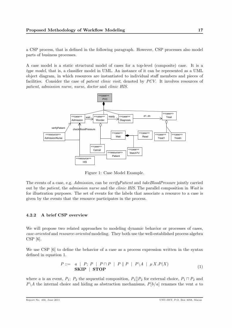
the parallel components, represent a parallel composition (PCV in Fig. 1). An associationbetween one component case and another is labeled by a set A of events to representtheir synchronization events (see in Fig. 1 the wait-association between cases Admission
andWonder and d1 . . . dn -association between case Diagnosis and case Treat), i.e. interfacesof interactions between the two cases. If the set is empty the association is not shown inthe diagram and the two component cases are independent. Associations must be acyclic.
Therefore, a case model is an extension to a use case model that is more informative, andprecisely defines the interfaces between cases and resources. This is important for collaborativeworkflow modeling, because
• interface events model how events (or actions) are jointly performed by different re-sources, including human resources and application software components (nature of agent-orientation),
• the resources can be distributed among a network of organizations (systems),
• the subcases in the case model can be cases from different organizations using supportedby different application software systems, and
• what events are automated by software and what events are not automated though beingmonitored and coordinated.
The use of interface events between parallel composition of cases is essential for component-basedworkflow modeling. Furthermore, structural relations between use cases, such as componentsof parallel compositions and choices, are formally defined as CSP processes. Therefore, modeldoes not have the problem of the semantically undefined relations of “includes” and “extends”between use cases. In practice, cases do not usually have recursive structures and the casemodel is of a tree structure. However, in theory the process of a component case C1 of a parallelcomposite or a choice composite case C can call for the process of composite case C to repeat.Therefore, a case model in general is a directed graph structure.
Event-based interactions among cases are the most significant concepts of collaborative andconcurrent processes, and sequencing relation between processes of cases are often realized bysynchronization events, i.e. triggering events. The philosophy of observing interactions of com-municating processes in CSP [6] and CCS [11] sequential composition in collaborative workflowsmodeling is an additional concept, and can be defined by synchronization. Hence, it is notexplicitly modeled in a case model.
It is important to note the difference between the notions of cases and work items (or activities),and those of business processes of cases and events (or activities) that execute work items. Abusiness process represents the story of performing events for a case from a start to an end inproviding a service or making a product, while an event is the performance of a work item or anactivity. Thus activities are atomic. In this sense, while a business process can be represented as
Report No. 450, June 2011 UNU-IIST, P.O. Box 3058, Macao
Proposed Methodology of Workflow Modeling 17
a CSP process, that is defined in the following paragraph. However, CSP processes also modelparts of business processes.
A case model is a static structural model of cases for a top-level (composite) case. It is atype model, that is, a classifier model in UML. An instance of it can be represented as a UMLobject diagram, in which resources are instantiated to individual staff members and pieces offacilities. Consider the case of patient clinic visit, denoted by PCV. It involves resources ofpatient, admission nurse, nurse, doctor and clinic HIS.
HIS
<<resource>>
Admission
<<case>>
Wonder
<<case>>
Diagnosis
<<case>> Treat
<<case>>
Cancel
<<case>>
Wait
<<case>>
Read
<<case>>
WatchTV
<<case>>
PVC
<<case>>
AdmissionNurse
<<resource>>
verifyPatientcheckBloodPressure
Patient
<<resource>>
wait ready d1..dn
Treat1
<<case>>
Treatn
<<case>>
Figure 1: Case Model Example.
The events of a case, e.g. Admission, can be verifyPatient and takeBloodPressure jointly carriedout by the patient, the admission nurse and the clinic HIS. The parallel composition in Wait isfor illustration purposes. The set of events for the labels that associate a resource to a case isgiven by the events that the resource participates in the process.
4.2.2 A brief CSP overview
We will propose two related approaches to modeling dynamic behavior or processes of cases,case-oriented and resource-orientedmodeling. They both use the well-established process algebraCSP [6].
We use CSP [6] to define the behavior of a case as a process expression written in the syntaxdefined in equation 1.
P ::= a | P ; P | P ⊓ P | P ‖ P | P\A | µX .P(X )SKIP | STOP
(1)
where a is an event, P1; P2 the sequential composition, P1[]P2 for external choice, P1 ⊓P2 andP\A the internal choice and hiding as abstraction mechanisms, P [b/a] renames the vent a to
Report No. 450, June 2011 UNU-IIST, P.O. Box 3058, Macao
Proposed Methodology of Workflow Modeling 18
be for reuse of processes, P1 ‖ P2 parallel composition, SKIP and STOP are respectively theprocess that does nothing but terminate and the process that deadlocks immediately. µX .P(X )denotes recursive equation definitions, and it can be written as the equation X = P(X ), whereX is a process variable.
When attributes become significant and value passing between processes is needed, events cansend a value c!(v) and receive a value c?(x ). Guards of processes can also be specified as g&P
meaning when g holds on the current event, then P can be executed, and it deadlocks otherwise.The internal choice and hiding are abstraction mechanisms for information hiding for verificationof properties. Notice that the case model does not use them.
For CSP, there are three complementary semantics models, trace model, stable failure model
and failure-divergence model for verification of safety, deadlock freedom and divergence freedomproperties of interactions among processes. A refinement calculus of CSP expressions is devel-oped for each of these semantic model to support algebraic reasoning. Verification of propertiesand refinement are support by the model checker FDR 2.
4.2.3 Case-oriented process model
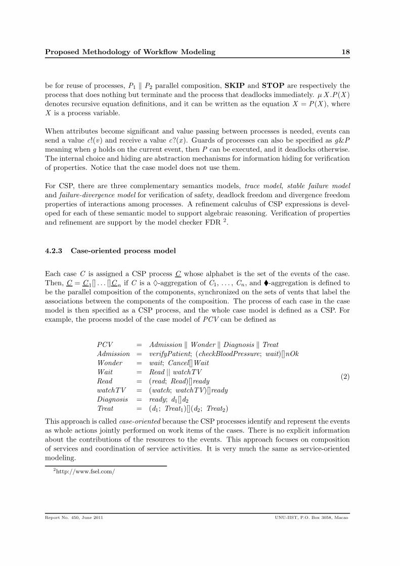
Each case C is assigned a CSP process C whose alphabet is the set of the events of the case.Then, C = C 1[] . . . []C n if C is a ♦-aggregation of C1, . . . , Cn , and �-aggregation is defined tobe the parallel composition of the components, synchronized on the sets of vents that label theassociations between the components of the composition. The process of each case in the casemodel is then specified as a CSP process, and the whole case model is defined as a CSP. Forexample, the process model of the case model of PCV can be defined as
PCV = Admission ‖ Wonder ‖ Diagnosis ‖ Treat
Admission = verifyPatient; (checkBloodPressure; wait)[]nOk
Wonder = wait; Cancel[]Wait
Wait = Read || watchTVRead = (read; Read)[]readywatchTV = (watch; watchTV)[]readyDiagnosis = ready; d1[]d2Treat = (d1; Treat1)[](d2; Treat2)
(2)
This approach is called case-oriented because the CSP processes identify and represent the eventsas whole actions jointly performed on work items of the cases. There is no explicit informationabout the contributions of the resources to the events. This approach focuses on compositionof services and coordination of service activities. It is very much the same as service-orientedmodeling.
2http://www.fsel.com/
Report No. 450, June 2011 UNU-IIST, P.O. Box 3058, Macao
Proposed Methodology of Workflow Modeling 19
4.2.4 Resource oriented modeling
The idea of agent-oriented modelling is followed in this approach. We identify the behavior thateach resource R performs in the process of a case C and represent it as a CSP process R-in-C ,and then parallel compose of the processes of all the resources in the case, synchronized on sameactivities, i.e. events that are contained in more than one resource. The CSP process for a caseC is then defined as the the following form
R1-in-C ‖ Rk -in-C
Each Ri -in-C has a structure of determined by the structure of the case C defined in the casemodel. For the example case PCV, the process of admission Nurse in PCV is defined as
AdmissionNurse = (verifyPatient ; checkBloodPressure; wait) 2 nOK
The consistency of a case-oriented process model and a resource-oriented process model for acase model is defined with respect to their equality with the algebraic laws of CSP processes.
4.2.5 Advantages of the methodology
In addition to the power of CSP, the proposed methodology enjoys the following advantages:
1. It allows to create a fully integrated model of workflows, yet supports separation of con-cerns.
2. It combines both techniques of service- and agent-oriented modeling.
3. Techniques and models of the component-based design of the application software systemsof the organizations can be reused in workflow modeling.
4. The model support component-based system evolution. New workflows can be definedand the underlying application components can be extended to support the newly addedworkflows.
5. Consistency checking of workflows can be done by checking deadlock and livelock freedomof the CSP process obtained from the model through FDR.
6. Feasibility of workflows can be checked if the interfaces of resources and the cases aresupported by the resource model.
7. The methodology can be easily extended to deal with real-time using the real-time CSP,and to deal with exception handling and compensation using Compensating CSP (cCSP) [4].
A possible concern from customers and ender users about the usability of CSP processes is thelack of support to their visualized representation. In fact, this is not a big issue as graphic
Report No. 450, June 2011 UNU-IIST, P.O. Box 3058, Macao
Proposed Methodology of Workflow Modeling 20
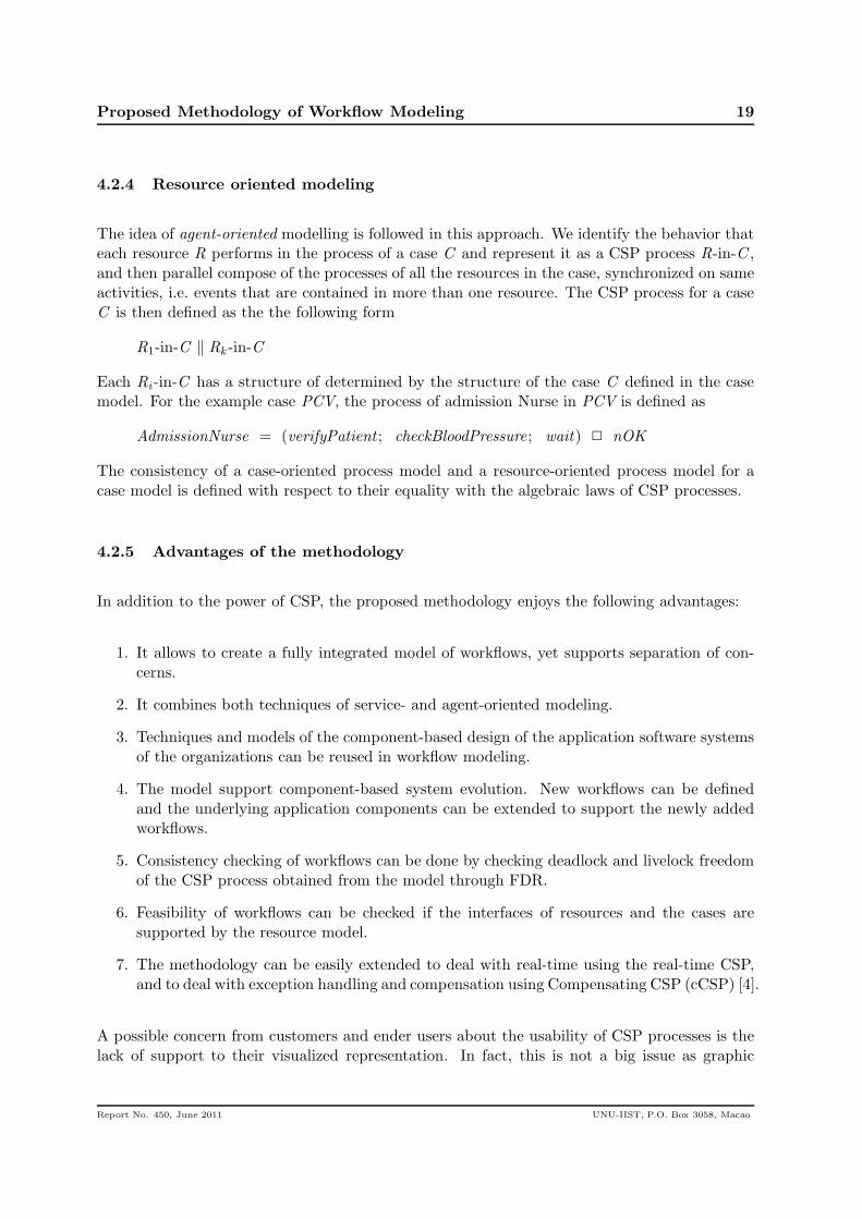
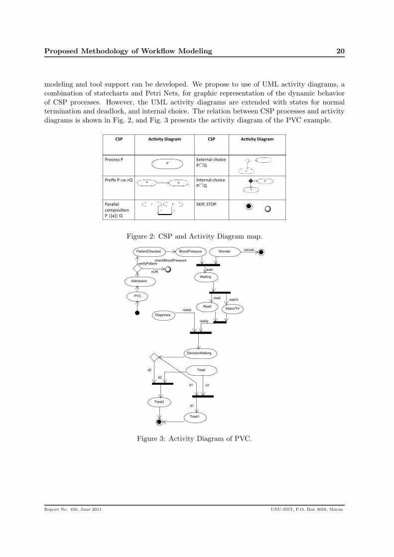
modeling and tool support can be developed. We propose to use of UML activity diagrams, acombination of statecharts and Petri Nets, for graphic representation of the dynamic behaviorof CSP processes. However, the UML activity diagrams are extended with states for normaltermination and deadlock, and internal choice. The relation between CSP processes and activitydiagrams is shown in Fig. 2, and Fig. 3 presents the activity diagram of the PVC example.
!"#$ %&'()*+$,)-./-0$ !"#$ %&'()*+$,)-./-0$
!"#$%&&'!'' ()*%"+,-'$.#/$%'
! 0''
!"%1)'!23,230'' 4+*%"+,-'$.#/$%'
! 0'
!,",--%-'
$#56#&/7#+''
!'89,:8'0''
;<4!=';>?!'
Figure 2: CSP and Activity Diagram map.
Admission
Wonder
Diagnosis
Treat1
PatientChecked
verifyPatient
PVC
BloodPressure
checkBloodPressure
ready
WatchTVRead
cancel
Waiting
waitnOK
d1
d2
watchread
Treat2
ready
DecisionMaking
Treat
d2
d1
d1
Figure 3: Activity Diagram of PVC.
Report No. 450, June 2011 UNU-IIST, P.O. Box 3058, Macao
Case Study: Blood Transfusion System 21
BloodTransfusion
<<case>>
Nurse
<<resource>>
Physician
<<resource>>
BloodBank
<<resource>>
StartTransfusion
<<case>>PreparePatient
<<case>>
PrepareBlood
<<case>>
StartProcedure
<<case>>
MonitorTransfusion
<<case>>
CompleteTransfusion
PatientAgree
<<case>>
PatientDisagree
<<case>>
OrderComplete
<<case>>
OrderIncomplete
<<case>>
Reaction
<<case>>
PatientOK
<<case>>
PatientIDinfo
<<case>>
BloodTypeOK
<<case>>
BloodTypeNOK
<<case>>
BloodAvailableOK
<<case>>
BloodAvailableNOK
<<case>>
obtainBloodType
firstPatientInfo
BloodIDinfo
<<case>>
PatientIDinfo
<<case>>
lastPatientInfo
BloodIDinfo
<<case>>
checkPatientInfo
firstBloodInfo, lastPatientInfo
checkPatientConcent, checkPhyOrder
checkBloodAvailability, checkBloodType
monitorReaction
started
patientReady
completeOrder
bloodReady transStarted
transEnded
firstBloodInfo
Patient
<<resource>>
Figure 4: Case Model.
5 Case Study: Blood Transfusion System
In this section, we present a blood transfusion system case study. We follow our previouslydefined methodology to modeling and analyzing such system.
The case study is based on a blood transfusion system benchmark [1,2]. The system consists ofa nurse, a physician and a patient. The nurse must collect the patient consent and the physicianauthorization and also checks the patient identification and material for the transfusion. Thephysician must fill out the transfusion order. The patient must provide his/her informationand also agree with the blood transfusion procedure. The nurse is responsible to collect theinformation from the patient, his/her consent, and the order from the physician. The nursealso carries out the blood transfusion and monitors the patient to handle an eventual adversereaction to the transfusion.
For the blood to be prepared, first the blood bank must check if it is available, and if thepatient’s blood type is known. In case the blood type is not known, the blood bank collectsa blood specimen to find out the patient’s blood type. During the blood transfusion someinformation must be collected from the patient. Before start the transfusion the nurse must checkall information about the patient, if the type is knew and the physician order is completed. Thepatient is monitored and in case of any reaction the procedure is stopped immediately. Finally,all information from the patient and the blood are checked again.
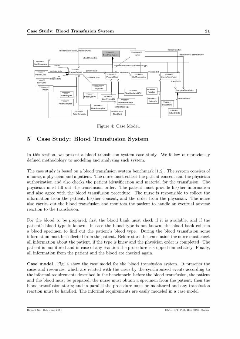
Case model. Fig. 4 show the case model for the blood transfusion system. It presents thecases and resources, which are related with the cases by the synchronized events according tothe informal requirements described in the benchmark: before the blood transfusion, the patientand the blood must be prepared; the nurse must obtain a specimen from the patient; then theblood transfusion starts; and in parallel the procedure must be monitored and any transfusionreaction must be handled. The informal requirements are easily modeled in a case model.
Report No. 450, June 2011 UNU-IIST, P.O. Box 3058, Macao
Case Study: Blood Transfusion System 22
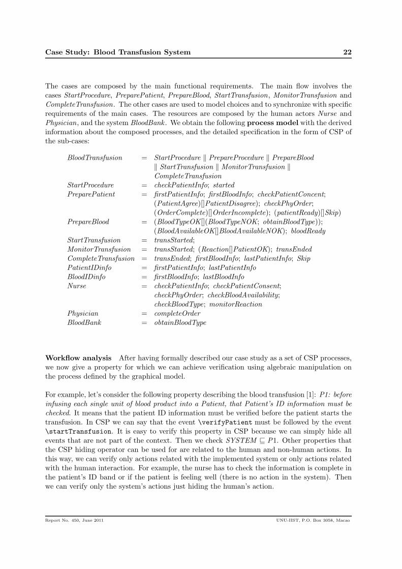
The cases are composed by the main functional requirements. The main flow involves thecases StartProcedure, PreparePatient, PrepareBlood, StartTransfusion, MonitorTransfusion andCompleteTransfusion. The other cases are used to model choices and to synchronize with specificrequirements of the main cases. The resources are composed by the human actors Nurse andPhysician, and the system BloodBank . We obtain the following process model with the derivedinformation about the composed processes, and the detailed specification in the form of CSP ofthe sub-cases:
BloodTransfusion = StartProcedure ‖ PrepareProcedure ‖ PrepareBlood
‖ StartTransfusion ‖ MonitorTransfusion ‖CompleteTransfusion
StartProcedure = checkPatientInfo; startedPreparePatient = firstPatientInfo; firstBloodInfo; checkPatientConcent;
(PatientAgree)[]PatientDisagree); checkPhyOrder;(OrderComplete)[]OrderIncomplete); (patientReady)[]Skip)
PrepareBlood = (BloodTypeOK[](BloodTypeNOK; obtainBloodType));(BloodAvailableOK[]BloodAvailableNOK); bloodReady
StartTransfusion = transStarted;MonitorTransfusion = transStarted; (Reaction[]PatientOK); transEndedCompleteTransfusion = transEnded; firstBloodInfo; lastPatientInfo; SkipPatientIDinfo = firstPatientInfo; lastPatientInfoBloodIDinfo = firstBloodInfo; lastBloodInfoNurse = checkPatientInfo; checkPatientConsent;
checkPhyOrder; checkBloodAvailability;checkBloodType; monitorReaction
Physician = completeOrder
BloodBank = obtainBloodType
Workflow analysis After having formally described our case study as a set of CSP processes,we now give a property for which we can achieve verification using algebraic manipulation onthe process defined by the graphical model.
For example, let’s consider the following property describing the blood transfusion [1]: P1: beforeinfusing each single unit of blood product into a Patient, that Patient’s ID information must be
checked. It means that the patient ID information must be verified before the patient starts thetransfusion. In CSP we can say that the event \verifyPatient must be followed by the event\startTransfusion. It is easy to verify this property in CSP because we can simply hide allevents that are not part of the context. Then we check SYSTEM ⊑ P1. Other properties thatthe CSP hiding operator can be used for are related to the human and non-human actions. Inthis way, we can verify only actions related with the implemented system or only actions relatedwith the human interaction. For example, the nurse has to check the information is complete inthe patient’s ID band or if the patient is feeling well (there is no action in the system). Thenwe can verify only the system’s actions just hiding the human’s action.
Report No. 450, June 2011 UNU-IIST, P.O. Box 3058, Macao
Conclusions and Future Work 23
6 Conclusions and Future Work
This paper has first discussed the need to design advanced workflow management systems tosupport the integration of healthcare systems through the new computing and communicationnetwork technology. We argued that for the design of such workflow management systems, thecurrent state of the art of workflow modeling, validation, verification and analysis is requiredto be improved. The main contribution is a proposal of modeling methodology that supportsthe reuse of model-driven and component-based techniques and tools in application softwaremodeling and design for workflow modeling. The main advantage of the proposed methodologyis the semantic integration of models of separated views of workflow models, the static viewsof the organization, the cases and the processes view of the workflows. The proposal has beenbased on the advantages of event-based process algebras CSP. It is used in this paper, over theother formalisms that are currently used for workflow modeling. The algebraic reasoning allowsthe consistently combines both service-oriented and agent-oriented techniques. The ability ofCSP in describing architectural operations is also important for component-based modeling.Yet, the abstraction mechanism of hiding and internal choice for information hiding allows thespecification and refinement of architectures models at different levels of abstraction.
The use of black-box interface models for application components provides clear separation ofand interfaces between workflows and application software components, providing flexibilityof system evolution. Application software components become resources of workflows in ourmethodology and clearly identify automated and non-automated activities. The use case modelthen represents the collaborative nature of resources in processes of services. The methodologyis illustrated with a motivating example and a benchmark case study.
Future work
This paper has largely focused on conceptual discussion. Most of the formal technical detailshave yet to be worked out. However, we do not see insurmountable challenges there. Furtherfundamental challenges that we foresee include the following problems.
1. There is a need to test the methodology on a real benchmark case study with the advancedissue of collaborative healthcare workflows.
2. Workflows are closely related to policies, practice guidelines, and regulations. All workflowmodeling approaches, including the one proposed in this paper, have these policies andguidelines hard coded into the temporal order of the events of the workflows. It wouldbe very much desirable for policies, (such as privacy and security policies) to become firstclass citizens in the model, so that workflows can be designed and monitored in an explicitaccordance to these policies.
3. For networked organizations, processes of cases cannot be short-lived (atomic) transac-tions. They are rather Long Running Transactions (LRTs). Most business process lan-
Report No. 450, June 2011 UNU-IIST, P.O. Box 3058, Macao
References 24
guages, such as BPEL, provide abstract facilities for programming LRTs. It is thus impor-tant to extend the case model and the process model for modeling LRT, or compensationwhen exceptions occur. For the process model, we will use the extension of CSP, calledcompensating CSP (cCSP).
Acknowledgements. This work is partly supported by the projects GAVES and ARV fundedby Macau Science and Technology Development Fund.
References
[1] Blood Transfusion Medical Benchmark. https://collab.cs.umass.edu/groups/laser_
library/wiki/04be2/BTBenchmarkDownloads.html.
[2] B. Chen, G. S. Avrunin, E. A. Henneman, L. A. Clarke, L. J. Osterweil, and P. L. Hen-neman. Analyzing Medical Processes. In Proceedings of the 30th Intl. Conf. on Software
Engineering, ICSE ’08, pages 623–632, New York, NY, USA, 2008. ACM.
[3] Z. Chen, Z. Liu, A. P. Ravn, V. Stolz, and N. Zhan. Refinement and verification incomponent-based model-driven design. Sci. Comp. Prog., 74(4):168–196, 2009.
[4] Z. Chen, Z. Liu, and J. Wang. Failure-divergence refinement of compensating communi-cating processes. In Proceedings of fM 2011, Lecture Notes in Computer Science 6664.Springer, 2011.
[5] eHealth Initiative. National progress report on ehealth. http://www.ehealthinitiative.org, July 2010.
[6] C. A. R. Hoare. Communicating Sequential Processes. Prentice-Hall, 1985.
[7] P. Hruby. Specification of workflow management systems with UML. In Proc. of the
OOPSLA96 Workshop on Business Object Design and Implementation, 1998.
[8] K. Jensen. Coloured Petri Nets: Basic concepts, analysis methods and practical use.Springer-Verlag, Berlin, 1996.
[9] C. Larman. Applying UML and Patterns: An Introduction to Object-Oriented Analysis and
Design and the Unified Process. Prentice-Hall, 2nd edition, 2001.
[10] Z. Liu, J. He, X. Li, and Y. Chen. A relational model for formal object-oriented requirementanalysis in UML. In 5th Intl. Conf. on Formal Engineering Methods, Lecture Notes in
Computer Science 2885, pages 641–664. Springer, 2003.
[11] R. Milner. Communication and Concurrency. Prentice Hall, 1989.
[12] National Academy of Enginnering. Grand challenges for engineering. http://www.
engineeringchallenges.org/cms/challenges.aspx, 2008.
Report No. 450, June 2011 UNU-IIST, P.O. Box 3058, Macao
References 25
[13] National E-Health Transition Authority. NEHTA Blueprint. Version 1.0, Draft for Consul-tation, August 2010.
[14] OMG. UML extensions for workflow process definition - request for proposal. OMG-document bom/2000-12-11, December 2000.
[15] Patricia Mechael, et al. Barriers and gaps affecting mHealth in low and middle incomecountries: Policy white paper. Technical report, Center for Global Health and EconomicDevelopment Earth Institute, Columbia University, May 2010.
[16] Rational. Business modelling with the UML and Rational Suite AnalystStudio. A RationalInc. Software White Paper, 2000.
[17] M. Shepherd. Challenges in health informatics. In Proceedings of the 40th Hawaii Interna-
tional Conference on System Sciences, 2007.
[18] W. van der Aalst. The application of petri nets to workflow management. The Journal of
Circuits, Systems and Computers, 8(1):21–66, 1998.
[19] W. van der Aalst and K. van Hee. Workflow Management: Models, Methods, and Systems.MIT Press, 2002.
[20] W. van der Aalst, M. Weske, and G. Wirtz. Advanced topics in workflow management:Issues, requirements, and solutions. Journal of integrated and process science, 7(3):49–77,2003.
[21] Vital Wave Consulting. mHealth for development: The opportunity of mobile technol-ogy for healthcare in the developing world. Washington, D.C. and Berkshire, UK: UNFoundation-Vodafone Foundation Partnership, 2009.
[22] WFMC. Workflowmanagement coalition terminology and glossary (WFMC-TC-1011).Technical report, Workflow Management Coalition, Brussels, 1996.
Report No. 450, June 2011 UNU-IIST, P.O. Box 3058, Macao