total ankle system - spot.pt
TRANSCRIPT

TRAUMA & EXTREMITIES GROUP
S U R G I C A L T E C H N I Q U E
Total Ankle System
DePuy International LtdSt Anthony’s RoadLeeds LS11 8DTEnglandTel: +44 (113) 387 7800Fax: +44 (113) 387 7890
REFERENCES1. Data on file at DePuy International Limited
This publication is not intended for distribution in the USA
Mobility™ is a trademark of DePuy International Limited.© 2005 DePuy International Limited. All rights reserved.
Cat No: 8555-00-004 version 2.
0086
Revised: 10/05

1
CONTENTSMobility™ Total Ankle System 2
Key Features of the Mobility™ Total Ankle System 3
Mobility™ Total Ankle System 4Surgical Technique
Step 1: Patient Preparation and 5Ankle Exposure
Step 2: Distal Tibial Resection 6
Step 3: Joint Sizing 7
Step 4: Tibial Window Preparation 8
Step 5: Superior Talar Flat Resection 10
Step 6: Transferral of Tibial 11Component Centre
Step 7: Talar Preparation: Superior 13and Posterior Sulci
Step 8: Talar Preparation: Posterior Flat, 14Anterior Flat and Anterior Sulcus
Step 9: Talar Profile Finishing 15
Step 10: Trial Insertion 16
Step 11: Component Implantation 17and Wound Closure
Post-operative Care 18
Product Ordering Information 19
IMPORTANT
DePuy accept no responsibility for unauthoriseduse of this document.
M o b i l i t y

2
MOBILITY™ TOTAL ANKLE SYSTEMI N T R O D U C T I O NUntil relatively recently the treatment of inflammatory joint disease and painful end-stagearthritis of the ankle was traditionally dominated by arthrodesis. Whilst ankle fusion provideswelcome pain relief, the loss of mobility of the joint often means that the outcome of theprocedure is less than ideal with associated arthritis developing in the surrounding joints anda pathological gait.Early designs for total ankle replacement prostheses were largely unsuccessful with highcomplication and failure rates. The early designs were associated with excessive wear,excessive constraint and a lack of stability, as well as problems such as talar subsidence andcomponent loosening.The search for a device that resolved these problems ultimately led to the use ofunconstrained, three-component mobile bearing prosthesis designs which, throughsuccessive advancements have resulted in a viable surgical alternative to ankle arthrodesis.Despite the principles of mobile bearing total ankle replacements being clinicallysubstantiated, the surgical procedure is complex and typically involves aggressive boneresection. Results can be unpredictable and inconsistent, and success is often dependenton the experience of the operating surgeon.The Mobility™ Total Ankle System is a three-component, cementless, unconstrained, mobile-bearing prosthesis with a dedicated instrumentation system. The prosthesis incorporatessome unique design modifications which allow minimal bone resection and the instrumentationallows repeatable and accurate surgical outcomes.The Mobility™ Total Ankle System was developed in conjunction with an experienced surgeondesign team, Dr Pascal F. Rippstein, Mr Peter L. R. Wood and Dr J. Chris Coetzee.
I N D I C AT I O N STotal ankle arthroplasty is indicated by ankle arthritis. Ankle arthritis originates from a varietyof causes including osteoarthritis, traumatic arthritis and rheumatoid arthritis. Each cause hasfactors that affect whether the implant is suitable for the patient and if a satisfactoryoutcome is achievable.In osteoarthritis patients the duration and degree of immobility caused by reduced jointspace, osteophytes, scarring and/or pain must be taken into account when considering ifthe implant is suitable since some patients may have been rigidly fibrosed for many years. Ifthe joint is very stiff, the movement regained after total ankle replacement may be modest.These factors may also pose some additional challenges during surgery.In traumatic arthritis patients, distal tibial ballooning with associated deformity, including fixedequinus, varus or valgus, must be considered when deciding if the implant is suitable for thesepatients. The number of surgical procedures performed on the patient, the number andlocation of previous surgical scars and the condition of the patient’s skin should also beconsidered during patient selection. Ankle replacement for this type of patient should beconsidered after post-traumatic healing. In many cases, up to 10 years are allowed for healing.In rheumatoid arthritis patients, the adjacent joints (subtalar and mid-tarsal) should beevaluated. Occasionally, the valgus hindfoot may preclude surgery or at least requirecorrective surgery either before, or after ankle replacement surgery. If the patient hasequally severe symptoms from arthritis of either the hip or knee then these joints shouldgenerally be treated first.
C O N T R A I N D I C AT I O N SContraindications include prior ankle joint infection which might still be latent, extendedavascular necrosis and peripheral neuropathy from any cause, including long-standing insulindependency from diabetes, very poor skin condition/vascularity, severe destruction of theankle geometry, and severe deformity of the ankle joint (greater than 20° varus/valgus).
IMPORTANT: DePuy accept no responsibility for unauthorised use of this document.

3
M o b i l i t y
Six Sizes of Components with Five Thicknessesof Bearing Inserts
The component sizes were determined to allow anaccurate anatomic fit. All three components narrowposteriorly to prevent impingement on the posteriorneurovascular bundles, medial flexor tendons and lateralposterior fibula and thereby prevent pain to the patient.The five thicknesses of bearing insert allow for variable jointligament strengths and soft tissue situations.
Dedicated Surgical Instrument Set
A comprehensive instrument set allowsaccurate and reproducible implantation of theMobility™ prosthesis. The instrumentation allowsthe tibial component to be accurately centredover the talus component in the frontal andsagittal planes. Bone resection guides allowreproducible tri-plane talar preparations whichcan all be performed without having to holdthe foot in the neutral position. In addition, allresection guide blocks allow good visibility ofthe joint space so that resections can bechecked visually.
Cobalt-Chrome Tibial Component
• Short, conical intramedullary stem- Provides primary fixation into tibia- Allows rotational adjustment of tibial component- Allows lateral-medial adjustment- Improves stress distribution within tibia
• Long tibial plate- Allows posterior overhang of posterior tibial cortex- Prevents non-uniform loading of the distal tibia- Narrow and rounded posterior aspect avoids
impingement with malleolus lateralis and medial soft tissues
• Porocoat® porous coating- Provides good primary fixation and subsequent
bone-ingrowth
UHMWPe Bearing Insert
• Restoration of normal ankle jointmobility- Unconstrained rotation and translation
with flat tibial plate- Unconstrained dorsiflexion and
plantarflexion and a small degree ofinversion/eversion with talar condyles
• Fully conforming congruent surfaces toprovide low contact stress- Flat upper surface of bearing conforms
with flat tibial plate and is smaller thanthe tibial plate to prevent edge loadingand reduce wear
- Fully conforming with profile of talarcomponent condyles
Cobalt-Chrome Talar Component
• Resurfacing tri-plane underside- Allows an accurate and reproducible 3-step talar resection technique- Allows minimal bone resection and leaves the medial and lateral sides
of the talus dome intact- Talar resections are the same for sizes 1-4 and sizes 5 & 6 allowing
greater system flexibility
• Deep talar sulcus- Reduces potential for bearing dislocations - Reduces potential of one-sided subsidence.
• Short, deep, anterior talar fins- Provide rotational stability and equilateral load transferral - Prevent one-sided subsidence- Provide good primary press fit fixation- Prevent penetration into the thin posterior subtalar joint
• Porocoat® porous coating- Provides good primary fixation and subsequent bone ingrowth
KEY FEATURES OF THE MOBILITY™ TOTAL ANKLE SYSTEMMobility™ Total Ankle System – A three-component mobile bearing ankle prosthesisdesigned on the principle of mobility with congruency
IMPORTANT: DePuy accept no responsibility for unauthorised use of this document.
Design Validation
Comparative wear, bearing push-out and talarcomponent stability and subsidence testing
showed theperformance ofMobility™ to be atleast equivalent,and superior inwear, whencompared with anexisting successfulthree-componentmobile bearingankle design.1

4
MOBILITY™ TOTAL ANKLE SYSTEM SURGICAL TECHNIQUEThroughout the procedure, particular care with skin retraction needs to beexercised in order to avoid pressure necrosis and delayed wound healing. Plantarflexion of the foot draws the skin edges together and if a self-retaining retractor hasbeen inserted when the foot was at 90° to the leg, the pressure it exerts willdramatically increase if the foot is plantar-flexed in an attempt to improveexposure. Self-retaining retractors should be released before altering the position ofthe foot to ensure this does not occur, or preferably their use should be avoidedaltogether.
IMPORTANT: DePuy accept no responsibility for unauthorised use of this document.
5
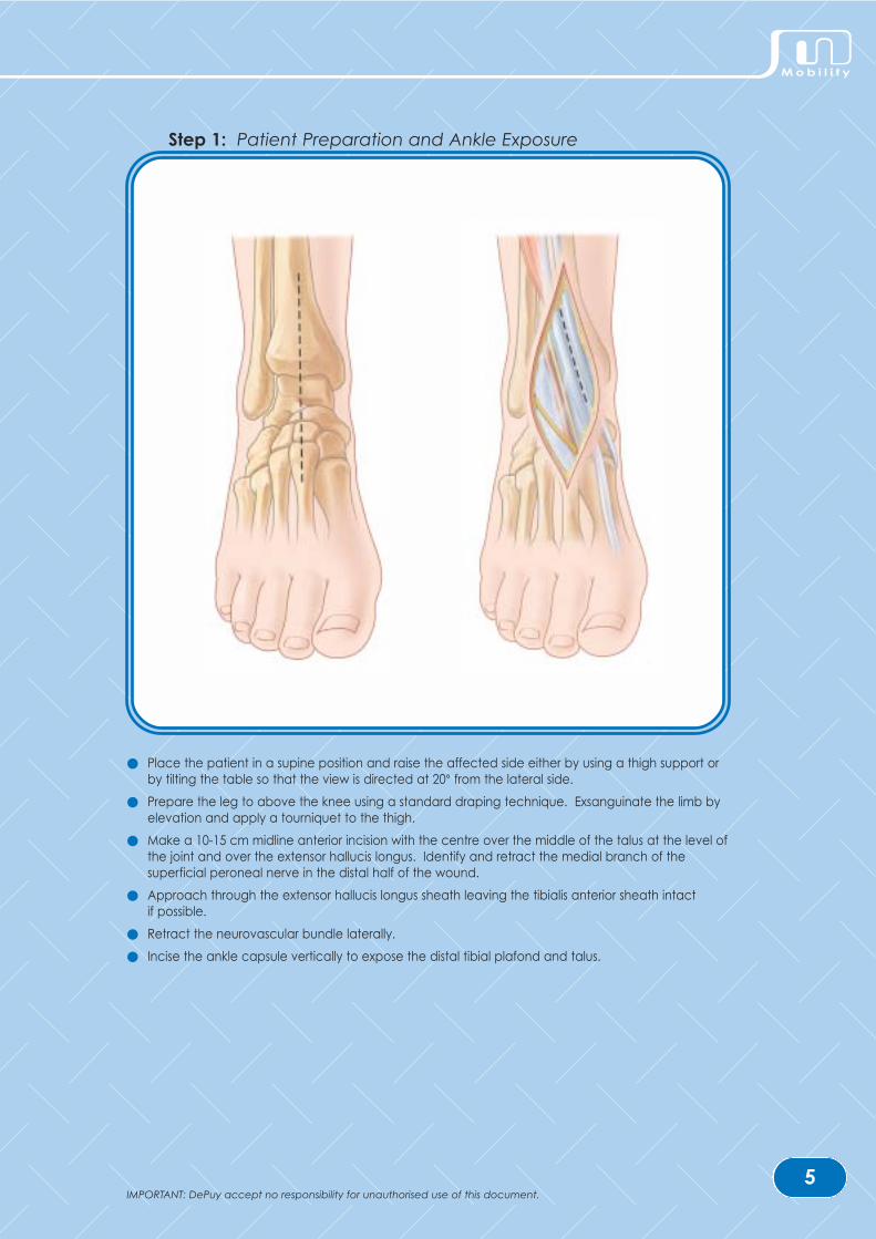
Step 1: Patient Preparation and Ankle Exposure
● Place the patient in a supine position and raise the affected side either by using a thigh support orby tilting the table so that the view is directed at 20° from the lateral side.
● Prepare the leg to above the knee using a standard draping technique. Exsanguinate the limb byelevation and apply a tourniquet to the thigh.
● Make a 10-15 cm midline anterior incision with the centre over the middle of the talus at the level ofthe joint and over the extensor hallucis longus. Identify and retract the medial branch of thesuperficial peroneal nerve in the distal half of the wound.
● Approach through the extensor hallucis longus sheath leaving the tibialis anterior sheath intact if possible.
● Retract the neurovascular bundle laterally.
● Incise the ankle capsule vertically to expose the distal tibial plafond and talus.
M o b i l i t y
IMPORTANT: DePuy accept no responsibility for unauthorised use of this document.

6
1
2 3 4a
b
12
Step 2: Distal Tibial Resection
● Assemble the yoke (1), tibial adjustment tube (2), tibial rod (3) and tibial cutting block (4) asillustrated. Position the yoke over the anterior crest of the proximal tibia and secure with 2.5 mm pins. A surgical swab may be used underneath the metal yoke to pad the proximal tibia,although care must be taken not to drive the pins through the swab and channel debris into the body. The tibial cutting block is angled to allow for a 5º slope posteriorly.
● Use the vertical adjustment (a) of the adjustment tube to position the tibial rod parallel to the longaxis of the tibia.
● Use the horizontal adjustment (b) of the adjustment tube to position the tibial cutting block so thatthe tibial resection will remove the roof of the tibial plafond.
● Secure the tibial cutting block with two pins. Place the pins so that they are on the same verticalrow of holes with one hole between them as shown above.
● Markings on the cutting face of the tibial cutting block indicate the medial/lateral width of the tibialcomponent (sizes 1-6). Resect the distal tibia using the non-depth marked thick oscillatingsawblade. Keep the blade in midline to avoid lateral and medial malleoli and medialneurovascular structures.
● Distract the joint using bone spreaders. Use the reciprocating sawblade to release the medial edgeof the tibial plateau by making a vertical cut in line with the medial side of the talus. This may bestarted with an osteotome.
● Remove the resected bone taking care not to lever against the medial malleolus, which can easilybe fractured.
IMPORTANT: DePuy accept no responsibility for unauthorised use of this document.

7
2mm
SIZE XSIZE X
3mm
5mm
7mm
9mm
11mm+ 8 mm
+ 6 mm
+ 4 mm
+ 2 mm
Distal TibialResection Required
Bearing Insert Thickness
3mm
ab
c
d
e
Step 3: Joint Sizing
● Insert the joint thickness trial between the resected distal tibia and the unresected talus (a). The joint thickness trial indicates the resection space required for the implantation of the thinnestbearing insert, 3 mm (b). For the implantation of thicker bearing inserts 5 mm, 7 mm, 9 mm and 11 mm there must be a clearance of 2, 4, 6 and 8 mm, respectively, in the joint space with the jointthickness trial. If the joint thickness trial cannot be inserted into the joint space, more distal tibiashould be resected and the joint sizing repeated (c). With the two pins secured in the bone, theproximal/distal and medial/lateral position of the tibial cutting block can be adjusted until the tibialresection is as required.
● Determine the required tibial component size by hooking the lip of the tibial profile trial behind theposterior aspect of the resected distal tibia (d). The tibial profile must be centred over the talardome to show the alignment of the tibial and talar components. The tibial profile trial should notimpinge with the fibula. This should be checked, especially posteriorly where the fibula convergestowards the centre of the ankle. If there is not adequate distance between the fibula and thelateral edge of the tibial profile trial, then a smaller size tibial component is required regardless ofthe length of the component.
● The tibial component size indicated will most often allow for a 2 mm posterior overhang of the distaltibia (e). If the tibial anatomy is such that the tibia is skewed obliquely posteriorly, the assessment ofdepth will not be entirely accurate. The width of the component is the important parameter notthe length. Due to the long tibial plate design which narrows posteriorly, there will always be somedegree of posterior support.
● All subsequent tibial cuts will be specific for the tibial component size selected.
M o b i l i t y
IMPORTANT: DePuy accept no responsibility for unauthorised use of this document.

8
a
b
c
Step 4: Tibial Window Preparation
● Select the appropriate tibial template size to match the tibial component indicated and assemblewith the tibial window cutting block. Hold together with the positioning forceps as shown (a).
● Position the assembly with the tibial template perfectly placed over the middle of the talus domeand in line with the axis of the talus (this can usually be found by aligning with the secondmetatarsal, but this is not always the case). The positioning of the tibial and talar componentdepends on the correct positioning of the tibial window cutting block since the talar componentposition is determined by the tibial component/jigs.
● The assembly may be further stabilised using the assistant stabiliser against the tibial template if required.
● Use the 6 mm tibial drill to prepare the proximal curvature of the tibial window resection (b). After drilling to the required depth insert the tibial window peg to stabilise the tibial cutting blockand template.
● Cut the medial and lateral sides of the tibial window to the depth indicated for the size of thecomponent using the depth-marked oscillating saw (c). Remove all jigs and join the cut sides tothe drill hole if necessary.
IMPORTANT: DePuy accept no responsibility for unauthorised use of this document.

9
SIZE XSIZE X
Step 4: Tibial Window Preparation (continued)
● Use the tibial window extractor to remove the tibial window bone. Slide the leading edge into theright tibial window saw cut and check the depth of the tibial stem with the appropriate depth markagainst the anterior tibial cortex.
● With the tibial window extractor at the correct depth, apply pressure to cut into the cancellousbone at the distal posterior end of the tibial window. Cut the subchondral bone by levering thetibial window extractor against the curvature of the talus. The bone can then be gently leveredfree. Care must be taken not to allow the tibial window bone portion to be projected from the jointspace into the air; this bone is required for grafting at the end of the procedure.
● Alternatively the tibial window may be removed using a curved osteotome levered against thetalus. The appropriate sized tibial profile trial is used to indicate the depth of the tibial stem for thecomponent size, the depth is marked in the bone through the stem hole in the tibial profile trial andthen a curved osteotome may be used to extract the tibial window.
● Once the tibial window is extracted, use the marked tibial window impactor to impact the tibial window to the required depth. If the impactor is placed in the tibial window correctly, thenthe marking ‘DISTAL’ will be visible on the instrument.
M o b i l i t y
IMPORTANT: DePuy accept no responsibility for unauthorised use of this document.

10
SIZE X
SIZE X
a
c
b
Step 5: Superior Talar Flat Resection
● Remove all osteophytes and the subchondral bone on the anterior aspect of the talus with a luer.Assemble the same size tibial template as used for the tibial window resection with the tibial stemand a talar drill guide; hold the assembly together with the positioning forceps. The talar drill guidethickness (+3, +5, +7 or +9-11) estimates the bearing insert thickness that will be implanted. Theassembly of the tibial template and selected thickness of the talar drill guide should fit snuglybetween the resected tibia and unresected talus (a). If the assembly is loose in the joint space, athicker talar drill guide should be tried until the assembly fits snugly.
● The varus/valgus and flexion/extension of the final implanted talar component is determined by thepositioning of two 2.5 mm drill bits inserted into the talus. With the foot held in a neutral position andthe appropriately sized tibial template/talar drill guide assembly aligned correctly, drill two 2.5 mmdrill bits into the outer two drill guide holes of the talar drill guide (b). Replace the drill bits with 2.5 mm pins after drilling. In the case of a particularly narrow talus, one of the drill bits may beinserted into the central hole of the talar drill guide. If the central hole is used the pin may impingewith other pins used later in the procedure if placed too deep. Ensure therefore, that the lasermarked depth guide on the drill bit is clearly visible and take extreme care not to drill greater thanthe depth mark on the 2.5 mm drill bit.
● Remove all instruments except the two pins that are inserted into the talus. Slide the standard talarflat cutting block (marked ‘0’) onto the pins with the arrow pointing posteriorly (c).
● Using the non-depth marked oscillating sawblade resect the superior flat of the talus keeping theblade flat and straight against the cutting block. Should more superior talar resection be required,the low talar flat cutting block (‘+1’) may be used.
IMPORTANT: DePuy accept no responsibility for unauthorised use of this document.

11
0
The medial/lateral and anterior/posterior centre of the tibial component is transferred to the talus to allow the talar component to be aligned relative to
the centre of the tibial component.
Step 6: Transferral of Tibial Component Centre
● With the talar flat cutting block still in position on the two pins, re-insert the tibial template/tibial stemassembly. The positioning forceps should not be used at this stage in the procedure as they willimpinge on other instruments.
● Assemble the talar centre guide as shown. Ensure that the sliding block is not locked in position andcan move freely. Insert the talar centre guide in between the tibial template and the talar flatcutting block so that the superior runners locate with the slots in the tibial template and the inferiorrunner locates with the slot in the talar flat cutting block. Make sure that the talar centre guiderunners are firmly pushed against the end of the tibial template location slots.
● With the foot held in the neutral position, all three instruments (the tibial template, the talar centreguide and the talar flat cutting block) should be parallel. If the instruments are loose within the jointspace, the plastic talar centre guide packing can be assembled onto the tibial template to fill thegap so that there is no movement between the instruments.
● Ensure that the talar centre guide is pushed firmly against the tibial template in the anterior/posterior direction.
● Ensure that the talar flat cutting block is firmly against the talus.
● Lift the loose sliding block of the talar centre guide and drop it down until it hits against the talar flatcutting block.
● Lock the sliding block in position when it is firmly stopped against the talar flat cutting block.Remove the talar centre guide assembly from the joint space. Do not move the position of thesliding block once it has been locked.
M o b i l i t y
IMPORTANT: DePuy accept no responsibility for unauthorised use of this document.

12
>60º
From this stage on, the talus will be cut for either sizes 1-4 or sizes 5 & 6. The talar component must be equal to or smaller than the tibial component.
Step 6: Transferral of Tibial Component Centre (continued)
● Remove the tibial template/tibial stem assembly from the joint space but leave the talar flat cuttingblock on the two talar pins.
● Plantarflex the foot and relocate the talar centre guide onto the talar flat cutting block so that thelocked sliding block meets the talar flat cutting block in exactly the same position as it did in theprevious step.
● Again, ensure that the talar flat cutting block is pushed firmly against the talus.
● With the talar centre guide and the talar flat cutting block in place, the end of the slot in the talarcentre guide indicates where the central point of the tibial component is with respect to the talus.Insert a 2.5 mm drill bit through the forked end of the talar centre guide into the talus. The drill bitmust be inserted as close to the end of the forked slot in the talar centre guide and at an angle ofat least 60°. Once drilled, replace with a 2.5 mm pin.
● Remove the talar centre guide leaving the central pin and talar flat cutting block in position. Theposition of the pin is where the centre of the tibial component will be over the talus and willbecome the centre of the talar component. Confirm visually that the insertion point of the pin is inthe centre of the talus medially/laterally and that the pin is in the centre of the tibial window whenthe foot is held in the neutral position. If the pin is not in the centre of the talus medially/laterally orit is not central in the tibial window, check the positioning of the tibial component.
● Check the anterior/posterior position of the pin – this will be the anterior/posterior centre of the talarcomponent. If the anatomy of the joint is such that there is any anterior protrusion of the talus, thepin will be positioned more posteriorly. It is at the discretion of the surgeon to decide if the centreof the talar component should be left posteriorly or if it should be moved slightly anteriorly toimplant the talar component in relation to the talar anatomy. The centre of the talar componentas indicated by the central pin can be checked at this stage by using a C-arm.
IMPORTANT: DePuy accept no responsibility for unauthorised use of this document.

13
SIZE
1 - 4
5 & 6
Step 7: Talar Preparation: Superior and Posterior Sulci
● The talar component size should be equal to or less than the tibial component size. The talarcomponent should never be wider than the talus and ideally there should be approximately 1-2 mm talar bone on both the medial and lateral sides. In case of doubt, always undersize, neveroversize. The talar jigs allow preparation for either sizes 1-4 (Black) or sizes 5 & 6 (White).
● Select the required size talar fin drill guide (1-4 Black; 5 & 6 White). Use the positioning forceps tohold and place the talar fin drill guide onto the top of the talar flat cutting block. Slide the talar findrill guide along the talar flat cutting block and the resected superior talar flat until the forked end isstopped by the central pin which is inserted in the talus.
● Use the 4.5 mm talar drill bit to drill four, full depth holes into the talus. The position of these fourholes determines the position of the talar jigs and the final position of the talar component.
● Remove all instruments and pins.
● Select the required size of talar trephine guide block (1-4 Black; 5 & 6 White). Use the positioningforceps to hold and place the block onto the resected talus. The four pegs in the talar trephineguide block fit into the four drill holes in the talus. Ensure that the trephine guide block is flat on theresected superior talus.
● Using combinations of the positioning forceps and assistant stabiliser to hold and secure the guideblock in position, trephine the superior and posterior talar sulci using the talar trephine.
● Remove the trephine guide block by lifting it off the talus in line with the pegs. Extreme cautionmust be taken not to break the talus by exerting medial or lateral force through the four pegsduring removal of the guide block.
M o b i l i t y
IMPORTANT: DePuy accept no responsibility for unauthorised use of this document.

14
SIZE
1 - 4
5 & 6
1st
Sulcus
2nd
Flat
Step 8: Talar Preparation: Posterior Flat, Anterior Flat and Anterior Sulcus
● Select the posterior cutting block of the chosen size (1-4 Black; 5 & 6 White). Hold with thepositioning forceps and place the two pegs marked ‘A’ into the two anterior talar holes. With thepegs inserted in the correct talar holes, the tongue of the posterior cutting block will fit flush into theposterior sulcus.
● Resect the posterior talar flat using the non-depth marked oscillating sawblade taking care not todrift medially or laterally with the blade and damage the soft tissue.
● Remove the posterior cutting block. Take care not to break the medial or lateral sides of the taluswith the pegs of the block.
● Select the anterior burr jig of the chosen size (1-4 Black; 5 & 6 White). Hold with the positioningforceps and place the two pegs marked ‘P’ into the two posterior talar holes. The flat posteriorportion of the jig will be flush against the posterior cut surface of the talus.
● Use the assistant stabiliser and the positioning forceps to steady the anterior burr jig during burring ofthe anterior talar flat and sulcus. Guide the depth stopped anterior flat burr around the templateof the burr jig to burr the talar anterior flat. Guide the anterior sulcus burr through the centre of theanterior burr jig to shape the anterior sulcus. The anterior sulcus burr will only fit in the anterior sulcusslot and will not fit around the whole template. Take care not to break the medial or lateral side ofthe talus by shaking the jig whilst using the burrs.
● Once the anterior talar flat and sulcus are prepared, remove the anterior burr jig from the talus.Take care not to break the medial or lateral side of the talus with the pegs of the block.
IMPORTANT: DePuy accept no responsibility for unauthorised use of this document.

15
Step 9: Talar Profile Finishing
● Finish the superior and posterior sulci by using the talar sulcus osteotome with a gentle tappingaction until the finished surface of the talus matches the talar profile template. Care must be takenwhen using the talar sulcus osteotome not to break off the posterior part of the talus.
● Gently place the plastic fin angle guide in one of the two pairs of talar drill holes. This indicates thedirection in which the osteotome is placed to cut out the small portion of bone between theanterior and posterior drill holes. Remove bone between the holes. Repeat for the other pair of holes.
● Extreme care must be taken not to break the medial or lateral sides of the talus by twisting orrocking the fin angle guide or the fin osteotome.
M o b i l i t y
IMPORTANT: DePuy accept no responsibility for unauthorised use of this document.

16
=
1 2 3 4 5 6
Tibialtrial
Talartrial
Bearingtrial
3mm 5mm 7mm 9mm 11mm
Step 10: Trial Insertion
● Select the appropriate size trials. There are six sizes of each component (tibial, bearing and talar)and five thicknesses of bearing (3 mm, 5 mm, 7 mm, 9 mm and 11 mm). The size of the talarcomponent must be the same or smaller than the tibial component; the bearing matches the talarcomponent and must be the same size.
● Insert the talar trial with narrow aspect directed posteriorly and the fins located in the prepared finslots. Do not use excessive force or rotation. Use the talar trial impactor with the handle directedthrough the resected tibial window to impact the talar trial. Ensure the talar component is wellseated posteriorly.
● Insert the tibial trial straight into the tibial window, using the positioning forceps to hold thecomponent if required. The curved aspect of the tibial trial should be directed posteriorly and theflat should be level with the anterior cortex of the tibia. There should be a 2 mm overhang on theposterior aspect of the tibia in the mid-section. However, and more importantly, if the tibial andtalar components have been centred correctly, the medial and lateral sides of the tibialcomponent should extend far enough for the bearing to be totally covered by the tibial plate. If this is not the case it is still possible at this stage to adjust the position of the tibial component byremoving a slice of bone from either the medial or lateral sides of the tibial window (depending onwhich direction you need to move the component) and replacing the side of bone on theopposite side.
● Use the tibial trial impactor to impact the trial into place. Do not use excessive force or rotation.
● Finally, insert the correct size of trial bearing insert. The small handle assists removal. Use a swablooped around the handle to apply gentle traction if needed.
IMPORTANT: DePuy accept no responsibility for unauthorised use of this document.

17
Step 11: Component Implantation and Wound Closure
● Insert the talar component first with narrow aspect directed posteriorly and the short deep fins inline with the prepared talar fin slots.
● Protect the articulating surface of the talar component with a bearing trial and insert the tibialcomponent with the curved aspect directed posteriorly. Ensure that the tibial component is seatedfirmly on the resected distal surface of the tibia by inspecting the sides of the component; thereshould be no gaps between the component and the bone.
● Trim and replace the bone previously resected from the tibial window and secure with slivers ofbone from the saw cuts. Check for, and remove any remaining osteophytes that may impinge onthe joint, taking care not to damage the articulating surfaces of the prosthesis.
● Insert the bearing insert using the bearing trials as necessary to determine the best fit.
● Test the joint’s range of motion and assess the varus/valgus of the hindfoot.
Ankle motion should range from 15º dorsiflexion to 20º plantarflexion. If extension beyond 15º cannotbe achieved, lengthening the gastrocnemius soleus complex at the musculo-tendinous junction or heelcord lengthening should be considered.
● Close the wound in layers.
M o b i l i t y
IMPORTANT: DePuy accept no responsibility for unauthorised use of this document.

18
POST-OPERATIVE CAREFor 3 weeks post-operatively, the patient is advised to wear a cast or a supporting,rigid boot of the type used for treating fractures. The boot should be used for afurther 3 weeks when walking outdoors. Regaining dorsiflexion presents the mainproblem for most patients and therefore active and passive dorsiflexion exercisesare vitally important. The difficulty restoring dorsiflexion is common following totalankle replacement and is not confined to one particular prosthesis design. Manypatients also require the supervision of a physiotherapist to overcome theirtendency to walk with the foot turned out.
IMPORTANT: DePuy accept no responsibility for unauthorised use of this document.

IMPORTANT: DePuy accept no responsibility for unauthorised use of this document.19
M o b i l i t y
PART NAME CATALOGUE NUMBER
2.5 mm Pin Extractors 8555-09-000
Positioning Forceps 8555-37-000
Assistant Stabiliser 8555-38-000
STEP 2Tibial Clamp 8555-00-000
Tibial Cutting Block 8555-02-001
Tibial Cutting Block Screw 8555-02-002
Tibial Rod 8555-02-000
STEP 3Joint Thickness Trial 8555-39-000
Tibial Profile Trial Size 1-2 8555-11-102
Tibial Profile Trial Size 3-4 8555-11-304
Tibial Profile Trial Size 5-6 8555-11-506
STEP 4 Tibial Window Cutting Block 8555-16-000
Tibial Template Size 1-6 8555-12-001 – -006
Tibial Window Peg 8555-17-000
Tibial Window Extractor 8555-19-001
Tibial Window Impactor 8555-19-000
STEP 5 Tibial Template Stem (2 per set) 8555-13-000
Talar Drill Guide 3 mm 8555-18-005
Talar Drill Guide 5 mm 8555-18-007
Talar Drill Guide 7 mm 8555-18-009
Talar Drill Guide 9-11 mm 8555-18-011
Talar Flat Cutting Block Std 8555-20-001
Talar Flat Cutting Block Low 8555-20-002
STEP 6 Talar Centre Guide 8555-21-000
Talar Centre Guide Packing 8555-21-001
STEP 7Talar Fin Drill Guide Assembly 8555-22-104Size 1-4
Talar Fin Drill Guide Assembly 8555-22-506Size 5-6
Talar Trephine 8555-28-000
Talar Trephine Guide Block 8555-23-104Size 1-4
Talar Trephine Guide Block 8555-22-506Size 5-6
PART NAME CATALOGUE NUMBER
STEP 8Talar Posterior Cutting Block 8555-24-104Size 1-4
Talar Posterior Cutting Block 8555-24-506Size 5-6
Talar Anterior Burr Jig 8555-25-104 Size 1-4
Talar Anterior Burr Jig 8555-25-506Size 5-6
STEP 9Talar Sulcus Osteotome 8555-30-000
Talar Profile Template 8555-32-000
Talar Fin Osteotome 8555-34-000
Talar Fin Osteotome 8555-34-111Angle Guide
STEP 10Talar Trial - Sizes 1- 6 8555-01-001 – -006
Tibial Trial - Sizes 1-6 8555-03-001 – -006
Insert Trial Size 6 (3, 5, 7, 9, 11 mm) 8555-05-603, -605,-607, -609, -611
Insert Trial Size 5 (3, 5, 7, 9, 11 mm) 8555-05-503, -505, -507, -509, -511
Insert Trial Size 4 (3, 5, 7, 9, 11 mm) 8555-05-403, -405, -407, -409, -411
Insert Trial Size 3 (3, 5, 7, 9, 11 mm) 8555-05-303, -305, -307, -309, -311
Insert Trial Size 2 (3, 5, 7, 9, 11 mm) 8555-05-203, -205, -207, -209, -211
Insert Trial Size 1 (3, 5, 7, 9, 11 mm) 8555-05-103, -105, -107, -109, -111
Talar Impactor Head 8555-27-104
Tibial Impactor Head 8555-27-111
Threaded Impactor Handle 8555-27-000
DRILL BITS AND BURRS6 mm Tibial Drill 8555-27-060(2 per set)
2.5 mm Talar Drill 8555-06-001(2 per set)
4.5 mm Talar Drill 8555-27-045(2 per set)
Talar Anterior Flat Burr 8555-29-000(2 per set)
Talar Anterior Sulcus Burr 8555-29-001(2 per set)
PRODUCT ORDERING INFORMATION

20
PART NAME CATALOGUE NUMBER
SINGLE USE ITEMS 2.5 mm x 70 mm K Wire 8555-06-000(5 per procedure)
2.5 mm x 45 mm K Wire 8555-06-002(optional 2 per procedure)
Recip Blade Stryker Hub 8555-07-00170 x 6 x 0.64 mm
Recip Blade Hall Hub 8555-07-00270 x 6 x 0.64 mm
Recip Blade Aesculap Hub 8555-07-00370 x 6 x 0.64 mm
Recip Blade Maxi-Driver Hub 8555-07-00470 x 6 x 0.64 mm
Osc Blade SOP 8555-40-00170 x 13 x 1.27 mm
Osc Blade EHD2K4K 8555-40-00270 x 13 x 1.27 mm
Osc Blade LHVP 8555-40-00370 x 13 x 1.27 mm
Osc Blade LHPP 8555-40-00470 x 13 x 1.27 mm
Osc Blade AO/SD 8555-40-00570 x 13 x 1.27 mm
Osc Blade LMD 8555-40-00670 x 13 x 1.27 mm
Osc Blade dm SOP 8555-40-00770 x 13 x 0.89 mm
Osc Blade EHD2K4K 8555-40-00870 x 13 x 0.89 mm
Osc Blade dm LHVP 8555-40-00970 x 13 x 0.89 mm
Osc Blade dm LHPP 8555-40-01070 x 13 x 0.89 mm
PART NAME CATALOGUE NUMBER
INSTRUMENT TRAYSMobility Instrument Tray A 8555-35-000
Mobility Instrument Tray B 8555-35-001
X-RAY TEMPLATES 8555-36-000
IMPLANTSMobility Tibial - Sizes 1-6 9555-03-001 – -006
Mobility Talar - Sizes 1-6 9555-01-001 – -006
Mobility Bearing Insert Size 1(3, 5, 7, 9, 11 mm) 9555-05-103, -105, -107, -109, -111
Mobility Bearing Insert Size 2(3, 5, 7, 9, 11 mm) 9555-05-203, -205, -207, -209, -211
Mobility Bearing Insert Size 3(3, 5, 7, 9, 11 mm) 9555-05-303, -305, -307, -309, -311
Mobility Bearing Insert Size 4(3, 5, 7, 9, 11 mm) 9555-05-403, -405, -407, -409, -411
Mobility Bearing Insert Size 5(3, 5, 7, 9, 11 mm) 9555-05-503, -505, -507, -509, -511
Mobility Bearing Insert Size 6(3, 5, 7, 9, 11 mm) 9555-05-603, -605, -607, -609, -611
IMPORTANT: DePuy accept no responsibility for unauthorised use of this document.

TRAUMA & EXTREMITIES GROUP
S U R G I C A L T E C H N I Q U E
Total Ankle System
DePuy International LtdSt Anthony’s RoadLeeds LS11 8DTEnglandTel: +44 (113) 387 7800Fax: +44 (113) 387 7890
REFERENCES1. Data on file at DePuy International Limited
This publication is not intended for distribution in the USA
Mobility™ is a trademark of DePuy International Limited.© 2005 DePuy International Limited. All rights reserved.
Cat No: 8555-00-004 version 2.
0086
Revised: 10/05