toshiba satellite m30 series portable personal …content.etilize.com/user-manual/10190482.pdffcc...
TRANSCRIPT
TOSHIBA Satellite M30 Series
Portable Personal ComputerUser’s Manual

Copyright© 2003 by TOSHIBA Corporation. All rights reserved. Under the copyright laws,this manual cannot be reproduced in any form without the prior written permissionof TOSHIBA. No patent liability is assumed, with respect to the use of the informa-tion contained herein.
TOSHIBA Satellite M30 Series Portable Personal Computer User’s Manual
First edition September 2003
Copyright authority for music, movies, computer programs, data bases and otherintellectual property covered by copyright laws belongs to the author or to thecopyright owner. Copyrighted material can be reproduced only for personal useor use within the home. Any other use beyond that stipulated above (includingconversion to digital format, alteration, transfer of copied material and distribu-tion on a network) without the permission of the copyright owner is a violationof copyright or author’s rights and is subject to civil damages or criminal action.Please comply with copyright laws in making any reproduction from this manual.
DisclaimerThis manual has been validated and reviewed for accuracy. The instructions anddescriptions it contains are accurate for the TOSHIBA Satellite M30 Series PortablePersonal Computer at the time of this manual’s production. However, succeedingcomputers and manuals are subject to change without notice. TOSHIBA assumesno liability for damages incurred directly or indirectly from errors, omissions ordiscrepancies between the computer and the manual.
TrademarksIBM is a registered trademark and IBM PC is a trademark of International BusinessMachines Corporation.Intel and Pentium are trademarks or registered trademarks of Intel Corporation or itssubsidiaries in the United States and other countries/regions.Windows and Microsoft are registered trademarks of Microsoft Corporation.Photo CD is a trademark of Eastman Kodak.
Other trademarks and registered trademarks not listed above may be used in thismanual.
FCC informationProduct Name : Satellite M30
Model number : PSM30
FCC notice "Declaration of ConformityInformation"This equipment has been tested and found to comply with the limits for a Class Bdigital device, pursuant to part 15 of the FCC rules. These limits are designed toprovide reasonable protection against harmful interference in a residential installa-tion. This equipment generates, uses and can radiate radio frequency energy and, ifnot installed and used in accordance with the instructions, may cause harmfulinterference to radio communications. However, there is no guarantee that interfer-ence will not occur in a particular installation. If this equipment does cause harmfulinterference to radio or television reception, which can be determined by turning theequipment off and on, the user is encouraged to try to correct the interference byone or more of the following measures:
❖❖❖❖❖ Reorient or relocate the receiving antenna.
❖❖❖❖❖ Increase the separation between the equipment and receiver.
❖❖❖❖❖ Connect the equipment into an outlet on a circuit different from that to whichthe receiver is connected.
❖❖❖❖❖ Consult the dealer or an experienced radio/TV technician for help.
WARNING: Only peripherals complying with the FCC class B limits maybe attached to this equipment. Operation with non-compliant peripher-als or peripherals not recommended by TOSHIBA is likely to result ininterference to radio and TV reception. Shielded cables must be usedbetween the external devices and the computer’s external monitor port,USB port, parallel port and microphone jack. Changes or modificationsmade to this equipment, not expressly approved by TOSHIBA or partiesauthorized by TOSHIBA could void the user’s authority to operate theequipment.
FCC conditionsThis device complies with part 15 of the FCC Rules. Operation is subject to thefollowing two conditions:
1. This device may not cause harmful interference.
2. This device must accept any interference received, including interference thatmay cause undesired operation.
ContactAddress: TOSHIBA America Information Systems, Inc.
9740 Irvine Boulevard
Irvine, California 92618-1697
Telephone: (949) 583-3000
EU Declaration of Conformity informationTOSHIBA declares, that the product: PSM30* conforms to the following Standards:
Supplementary Information: “The product complies with the requirementsof the Low Voltage Directive 73/23/EEC, theEMC Directive 89/336/EEC and/or the R&TTEDirective 1999/05/EEC.”
This product is carrying the CE-Mark in accordance with the related EuropeanDirectives. Responsible for CE-Marking is TOSHIBA Europe, Hammfelddamm 8,41460 Neuss, Germany.
VCCI Class B Information
Modem warning noticeConformity StatementThe equipment has been approved to [Commission Decision “CTR21”] for pan-European single terminal connection to the Public Switched Telephone Network(PSTN).
However, due to differences between the individual PSTNs provided in differentcountries/regions the approval does not, of itself, give an unconditional assuranceof successful operation on every PSTN network termination point.
In the event of problems, you should contact your equipment supplier in the firstinstance.
Network Compatibility StatementThis product is designed to work with, and is compatible with the followingnetworks. It has been tested to and found to conform with the additional require-ments conditional in EG 201 121.
Germany ATAAB AN005, AN006, AN007, AN009, AN010 andDE03, 04, 05, 08, 09, 12, 14, 17
Greece ATAAB AN005,AN006 a, d GR01, 02, 03, 04
Portugal ATAAB AN001, 005, 006, 007, 011 and P03, 04, 08, 10
Spain ATAAB AN005, 007, 012 and ES01
Switzerland ATAAB AN002
All other countries/regions ATAAB AN003, 004
Specific switch settings or software setup are required for each network, please referto the relevant sections of the user guide for more details.
The hookflash (timed break register recall) function is subject to separate nationaltype approvals. It has not been tested for conformity to national type regulations,and no guarantee of successful operation of that specific function on specificnational networks can be given.

Japan regulations
Region selection
If you are using the computer in Japan, technical regulations described in theTelecommunications Business Law require that you select the Japan region mode. Itis illegal to use the modem in Japan with any other selection.
Redial
Up to two redial attempts can be made. If more than two redial attempts are made, themodem will return Black Listed . If you are experiencing problems with the BlackListed code, set the interval between redials at one minute or longer.
Japan’s Telecommunications Business Law permits up to two redials on analoguetelephones, but the redials must be made within a total of three minutes.
The internal modem is approved by Japan Approvals Institute for Telecommunica-tions Equipment.
A02-0604JP
Pursuant to FCC CFR 47, Part 68:
When you are ready to install or use the modem, call your local telephone companyand give them the following information:
❖❖❖❖❖ The telephone number of the line to which you will connect the modem
❖❖❖❖❖ The registration number that is located on the device
The FCC registration number of the modem will be found on either the device whichis to be installed, or, if already installed, on the bottom of the computer outside of themain system label.
❖❖❖❖❖ The Ringer Equivalence Number (REN) of the modem, which can vary. For theREN of your modem, refer to your modem’s label.
The modem connects to the telephone line by means of a standard jack called theUSOC RJ11C.
Type of service
Your modem is designed to be used on standard-device telephone lines. Connectionto telephone company-provided coin service (central office implemented systems) isprohibited. Connection to party lines service is subject to state tariffs. If you haveany questions about your telephone line, such as how many pieces of equipment youcan connect to it, the telephone company will provide this information upon request.

Telephone company procedures
The goal of the telephone company is to provide you with the best service it can. Inorder to do this, it may occasionally be necessary for them to make changes in theirequipment, operations, or procedures. If these changes might affect your service orthe operation of your equipment, the telephone company will give you notice inwriting to allow you to make any changes necessary to maintain uninterruptedservice.
If problems arise
If any of your telephone equipment is not operating properly, you should immedi-ately remove it from your telephone line, as it may cause harm to the telephonenetwork. If the telephone company notes a problem, they may temporarily discon-tinue service. When practical, they will notify you in advance of this disconnection.If advance notice is not feasible, you will be notified as soon as possible. Whenyou are notified, you will be given the opportunity to correct the problem andinformed of your right to file a complaint with the FCC. In the event repairs are everneeded on your modem, they should be performed by TOSHIBA Corporation or anauthorized representative of TOSHIBA Corporation.
Disconnection
If you should ever decide to permanently disconnect your modem from its presentline, please call the telephone company and let them know of this change.
Fax branding
The Telephone Consumer Protection Act of 1991 makes it unlawful for any personto use a computer or other electronic device to send any message via a telephonefax machine unless such message clearly contains in a margin at the top or bottomof each transmitted page or on the first page of the transmission, the date and time itis sent and an identification of the business, other entity or individual sending themessage and the telephone number of the sending machine or such business, otherentity or individual. In order to program this information into your fax modem, youshould complete the setup of your fax software before sending messages.
Instructions for IC CS-03 certified equipment1 The Industry Canada label identifies certified equipment. This certification
means that the equipment meets certain telecommunications network protective,operational and safety requirements as prescribed in the appropriate TerminalEquipment Technical Requirements document(s). The Department does notguarantee the equipment will operate to the user’s satisfaction.
Before installing this equipment, users should ensure that it is permissible to beconnected to the facilities of the local telecommunications company. Theequipment must also be installed using an acceptable method of connection.
The customer should be aware that compliance with the above conditions maynot prevent degradation of service in some situations. Repairs to certifiedequipment should be coordinated by a representative designated by thesupplier. Any repairs or alterations made by the user to this equipment, orequipment malfunctions, may give the telecommunications company cause torequest the user to disconnect the equipment.
Users should ensure for their own protection that the electrical ground connec-tions of the power utility, telephone lines and internal metallic water pipe system,if present, are connected together. This precaution may be particularly importantin rural areas.
CAUTION: Users should not attempt to make such connections them-selves, but should contact the appropriate electric inspection authority,or electrician, as appropriate.
2 The user manual of analog equipment must contain the equipment’s RingerEquivalence Number (REN) and an explanation notice similar to the following:
The Ringer Equivalence Number (REN) of the modem, which can vary. For theREN of your modem, refer to your modem’s label.
NOTICE: The Ringer Equivalence Number (REN) assigned to eachterminal device provides an indication of the maximum number ofterminals allowed to be connected to a telephone interface. The termina-tion on an interface may consist of any combination of devices subjectonly to the requirement that the sum of the Ringer Equivalence Numbersof all the devices does not exceed 5.

3 The standard connecting arrangement (telephone jack type) for this equipment isjack type(s): USOC RJ11C.
The IC registration number of the modem is shown below.
Canada: 1353A-L4AINT
Notes for Users in Australia and New Zealand
Modem warning notice for Australia
Modems connected to the Australian telecoms network must have a valid Austelpermit. This modem has been designed to specifically configure to ensure compli-ance with Austel standards when the country/region selection is set to Australia.The use of other country/region setting while the modem is attached to theAustralian PSTN would result in you modem being operated in a non-compliantmanner. To verify that the country/region is correctly set, enter the command ATIwhich displays the currently active setting.
To set the country/region permanently to Australia, enter the following commandsequence:
AT%TE=1ATS133=1AT&FAT&WAT%TE=0ATZ
Failure to set the modem to the Australia country/region setting as shown abovewill result in the modem being operated in a non-compliant manner. Consequently,there would be no permit in force for this equipment and the Telecoms Act 1991prescribes a penalty of $12,000 for the connection of non-permitted equipment.
Notes for use of this device in New Zealand
❖❖❖❖❖ The grant of a Telepermit for a device in no way indicates Telecom acceptanceof responsibility for the correct operation of that device under all operatingconditions. In particular the higher speeds at which this modem is capable ofoperating depend on a specific network implementation which is only one ofmany ways of delivering high quality voice telephony to customers. Failure tooperate should not be reported as a fault to Telecom.
❖❖❖❖❖ In addition to satisfactory line conditions a modem can only work properly if:
a/ it is compatible with the modem at the other end of the call and
b/ the application using the modem is compatible with the application at theother end of the call - e.g., accessing the Internet requires suitablesoftware in addition to a modem.
❖❖❖❖❖ This equipment shall not be used in any manner which could constitute anuisance to other Telecom customers.
❖❖❖❖❖ Some parameters required for compliance with Telecom’s PTC Specificationsare dependent on the equipment (PC) associated with this modem. Theassociated equipment shall be set to operate within the following limits forcompliance with Telecom Specifications:
a/ There shall be no more than 10 call attempts to the same number withinany 30 minute period for any single manual call initiation, and
b/ The equipment shall go on-hook for a period of not less than 30 secondsbetween the end of one attempt and the beginning of the next.
c/ Automatic calls to different numbers shall be not less than 5 secondsapart.
❖❖❖❖❖ Immediately disconnect this equipment should it become physically damaged,and arrange for its disposal or repair.
❖❖❖❖❖ The correct settings for use with this modem in New Zealand are as follows:
ATB0 (CCITT operation)
AT&G2 (1800 Hz guard tone)
AT&P1 (Decadic dialing make-break ratio =33%/67%)
ATS0=0 (not auto answer)
ATS6=4 (Blind dial delay)
ATS7=less than 90 (Time to wait to carrier after dialing)
ATS10=less than 150 (loss of carrier to hangup delay, factory default of 15recommended)

ATS11=90 (DTMF dialing on/off duration=90 ms)
ATX2 (Dial tone detect, but not (U.S.A.) call progress detect)
❖❖❖❖❖ When used in the Auto Answer mode, the S0 register must be set with a valueof 3 or 4. This ensures:
(a) a person calling your modem will hear a short burst of ringing before themodem answers. This confirms that the call has been successfullyswitched through the network.
(b) caller identification information (which occurs between the first andsecond ring cadences) is not destroyed.
❖❖❖❖❖ The preferred method of dialing is to use DTMF tones (ATDT...) as this isfaster and more reliable than pulse (decadic) dialing. If for some reason youmust use decadic dialing, your communications program must be set up torecord numbers using the following translation table as this modem does notimplement the New Zealand “Reverse Dialing” standard.
Number to be dialed: 0 1 2 3 4 5 6 7 8 9
Number to program into computer: 0 9 8 7 6 5 4 3 2 1
Note that where DTMF dialing is used, the numbers should be enterednormally.
❖❖❖❖❖ The transmit level from this device is set at a fixed level and because of thisthere may be circumstances where the performance is less than optimal. Beforereporting such occurrences as faults, please check the line with a standardTelepermitted telephone, and only report a fault if the phone performance isimpaired.
❖❖❖❖❖ It is recommended that this equipment be disconnected from the Telecom lineduring electrical storms.
❖❖❖❖❖ When relocating the equipment, always disconnect the Telecom line connec-tion before the power connection, and reconnect the power first.
❖❖❖❖❖ This equipment may not be compatible with Telecom Distinctive Alert ca-dences and services such as FaxAbility.
NOTE: Fault callouts caused by any of the above causes may incur acharge from Telecom.

General conditions
As required by PTC 100, please ensure that this office is advised of any changes tothe specifications of these products which might affect compliance with the relevantPTC Specifications.
The grant of this Telepermit is specific to the above products with the marketingdescription as stated on the Telepermit label artwork. The Telepermit may not beassigned to other parties or other products without Telecom approval.
A Telepermit artwork for each device is included from which you may prepare anynumber of Telepermit labels subject to the general instructions on format, size andcolour on the attached sheet.
The Telepermit label must be displayed on the product at all times as proof topurchasers and service personnel that the product is able to be legitimatelyconnected to the Telecom network.
The Telepermit label may also be shown on the packaging of the product and in thesales literature, as required in PTC 100.
The charge for a Telepermit assessment is $337.50. An additional charge of $337.50is payable where an assessment is based on reports against non-Telecom NewZealand Specifications. $112.50 is charged for each variation when submitted at thesame time as the original.
An invoice for $NZ1237.50 will be sent under separate cover.

COMPLIES WITH FDA RADIATIONPERFORMANCE STANDARDS, 21CFR SUBCHAPTER J. 130KMTManufactured by Panasonic Communi-cations Co., Ltd.1-62, 4-Chome Minoshima Hakata-KuFukuoka, Japan
CLASS 1 LASER PRODUCT LASER KLASSE 1
Optical disc drive safety instructions
NOTE: Be sure to check the international precautions at the end of thissection.
CD-RW/DVD-ROM drives
Panasonic UJDA750
CAUTIONS: 1. The CD-RW/DVD-ROM drive employs a laser system. Toensure proper use of this product, please read thisinstruction manual carefully and retain for futurereference. Should the unit ever require maintenance,contact an authorized service location.
2. Use of controls, adjustments or the performance ofprocedures other than those specified may result inhazardous radiation exposure.
3. To prevent direct exposure to the laser beam, do not tryto open the enclosure.
Location of the required label
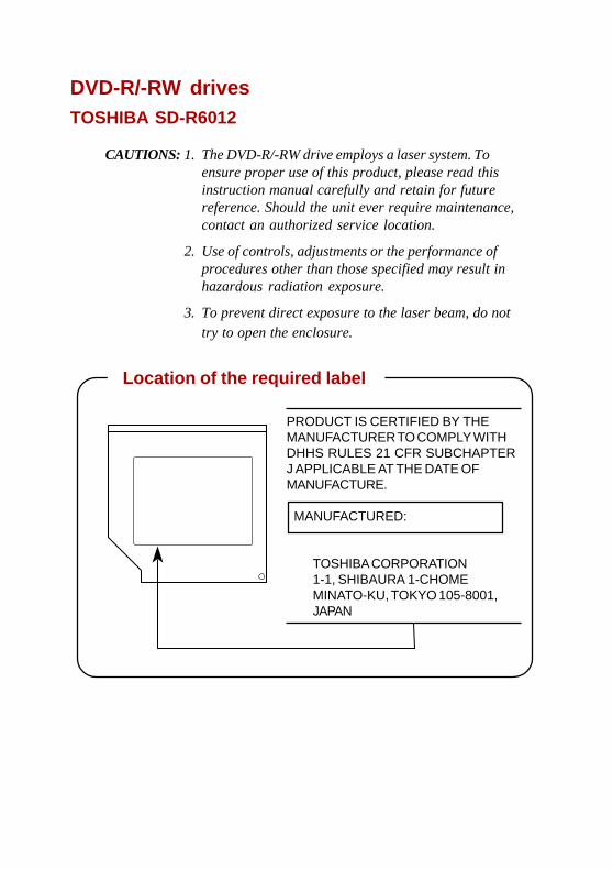
PRODUCT IS CERTIFIED BY THEMANUFACTURER TO COMPLY WITHDHHS RULES 21 CFR SUBCHAPTERJ APPLICABLE AT THE DATE OFMANUFACTURE.
MANUFACTURED:
TOSHIBA CORPORATION1-1, SHIBAURA 1-CHOMEMINATO-KU, TOKYO 105-8001,JAPAN
DVD-R/-RW drivesTOSHIBA SD-R6012
CAUTIONS: 1. The DVD-R/-RW drive employs a laser system. Toensure proper use of this product, please read thisinstruction manual carefully and retain for futurereference. Should the unit ever require maintenance,contact an authorized service location.
2. Use of controls, adjustments or the performance ofprocedures other than those specified may result inhazardous radiation exposure.
3. To prevent direct exposure to the laser beam, do nottry to open the enclosure.
Location of the required label

COMPLIES WITH FDA RADIATIONPERFORMANCE STANDARDS, 21CFR SUBCHAPTER J. 130KMTManufactured by Panasonic Communi-cations Co., Ltd.1-62, 4-Chome Minoshima Hakata-KuFukuoka, Japan
CLASS 1 LASER PRODUCT LASER KLASSE 1
DVD Multi drivesPanasonic UJ-811
CAUTIONS: 1. The DVD Multi drive employs a laser system. To ensureproper use of this product, please read this instructionmanual carefully and retain for future reference. Shouldthe unit ever require maintenance, contact an autho-rized service location.
2. Use of controls, adjustments or the performance ofprocedures other than those specified may result inhazardous radiation exposure.
3. To prevent direct exposure to the laser beam, do not tryto open the enclosure.
Location of the required label

THIS PRODUCT COMPLIES WITHDHHS RULES 21 CFR CHAPTER 1,SUBCHAPTER J APPLICABLE ATDATE OF MANUFACTURE.
MANUFACTURED:
Manufactured byTEAC Corporation3-7-3 Naka-cho, Musashino-shi,Tokyo, Japan
TEAC DV-W22E
This product has been designed and manufactured according to FDAregulations “title 21. CFR. chapter 1, subchapter J. based on theradiation Control for Health and Safety Act of 1968,” and is classifiedas a class 1 laser product. There is no hazardous invisible laserradiation during operation because invisible laser radiation emittedinside of this product is completely confined in the protective hous-ings.
The label required in this regulation is shown below.
CAUTION
Use of controls or adjustments or performance of procedures otherthan those specified herein may result in hazardous radiation exposure.
Optical pickup
Type : PSH202
Manufacturer :TEAC
Laser output : Less than 1.5mW (Play) and 53.3mW(Record) on the objective lens
Wavelength :779-789nm (CD)
652 ~ 660nm (DVD)
Location of the required label

International precautions
CAUTION: This appliance contains a lasersystem and is classified as a “CLASS 1 LASERPRODUCT.” To use this model properly, readthe instruction manual carefully and keep thismanual for your future reference. In case of anytrouble with this model, please contact yournearest “AUTHORIZED service station.” Toprevent direct exposure to the laser beam, donot try to open the enclosure
VORSICHT: Dieses Gerät enthält ein Laser-System und ist als “LASERSCHUTZKLASSE 1PRODUKT” klassifiziert. Für den richtigenGebrauch dieses Modells lesen Sie bitte dieBedienungsanleitung sorgfältig durch undbewahren diese bitte als Referenz auf. FallsProbleme mit diesem Modell auftreten,benachrichtigen Sie bitte die nächste“autorisierte Service-Vertretung”. Um einendirekten Kontakt mit dem Laserstrahl zuvermeiden darf das Gerät nicht geöffnet werden.
ADVARSEL: Denne mærking er anbragtudvendigt på apparatet og indikerer, atapparatet arbejder med laserstråler af klasse 1,hviket betyder, at der anvendes laserstrlier afsvageste klasse, og at man ikke på apparatetsyderside kan bilve udsat for utilladellg kraftigstråling.
APPARATET BOR KUN ÅBNES AF FAGFOLKMED SÆRLIGT KENDSKAB TIL APPARATERMED LASERSTRÅLER!
Indvendigt i apparatet er anbragt den hergengivne advarselsmækning, som advarer imodat foretage sådanne indgreb i apparatet, at mankan komme til at udsætte sig for laserstråling.
CLASS 1 LASER PRODUCTLASERSCHUTZKLASSE 1PRODUKTTO EN60825
ADVERSEL: USYNLIGLASERSTRÅLING VED ÅBNING,NÅR SIKKERHEDSAF-BRYDER
ER UDE AF FUNKTION.UNDGÅ UDSÆTTELSE FORSTRÅLING
CLASS 1 LASER PRODUCTAPPAREIL Å LASER DECLASSE 1LASER KLASSE 1 PRODUKTTO EN 60825-1

OBS! Apparaten innehåller laserkomponentsom avger laserstråining överstigande gränsenför laserklass 1.
VAROITUS. Suojakoteloa si saa avata. Laitesisältää laserdiodin, joka lähetää näkymätöntäsilmilie vaarallista lasersäteilyä.
CAUTION: USE OF CONTROLS OR ADJUST-MENTS OR PERFORMANCE OF PROCE-DURES OTHER THAN THOSE SPECIFIED INTHE OWNER’S MANUAL MAY RESULT INHAZARDOUS RADIATION EXPOSURE.
VORSICHT: DIE VERWENDUNG VONANDEREN STEURUNGEN ODEREINSTELLUNGEN ODER DASDURCHFÜHREN VON ANDERENVORGÄNGEN ALS IN DERBEDIENUNGSANLEITUNG BESCHRIEBENKÖNNEN GEFÄHRLICHESTRAHLENEXPOSITIONEN ZUR FOLGEHABEN.

xix
Table of Contents
PrefaceManual contents .............................................................................. xxviConventions.................................................................................... xxviiAbbreviations ................................................................................... xxviiIcons ................................................................................................ xxviiKeys................................................................................................. xxviiKey operation ................................................................................. xxviiiDisplay ............................................................................................ xxviiiMessages ....................................................................................... xxviii
General PrecautionsStress injury..................................................................................... xxixHeat injury ........................................................................................ xxixPressure or impact damage ........................................................... xxixPC card overheating ........................................................................ xxxMobile phone .................................................................................... xxxCentral Processing Unit (CPU) Performance Disclaimer .............. xxx
Chapter 1 IntroductionEquipment checklist ......................................................................... 1-1Hardware ........................................................................................... 1-1Software ............................................................................................1-1Documentation .................................................................................. 1-2
Features ............................................................................................. 1-2Special features ................................................................................. 1-7Utilities ...............................................................................................1-9Options .............................................................................................1-10
Chapter 2 The Grand TourFront with the display closed ...........................................................2-1Left side ............................................................................................. 2-2Right side ........................................................................................... 2-3

xx
Back side ........................................................................................... 2-4Underside ........................................................................................... 2-6Front with the display open .............................................................. 2-7Indicators ........................................................................................... 2-9USB diskette drive........................................................................... 2-12Optical media drives .......................................................................2-13Region codes for DVD drives and media .........................................2-13Writable discs .................................................................................. 2-13Formats ........................................................................................... 2-14CD-RW/DVD-ROM drive .................................................................2-14DVD-R/-RW drive ............................................................................ 2-15DVD Multi drive ................................................................................2-15
Universal AC adaptor ...................................................................... 2-16
Chapter 3 Getting StartedSetting up your work space ............................................................. 3-1General conditions ............................................................................. 3-2Placement of the computer ................................................................ 3-2Seating and posture .......................................................................... 3-3Lighting .............................................................................................. 3-4Work habits ........................................................................................ 3-4
Connecting the universal AC adaptor ............................................. 3-5Opening the display .......................................................................... 3-6Turning on the power........................................................................ 3-6Starting up for the first time ............................................................. 3-7Turning off the power ....................................................................... 3-7Shut Down mode (Boot mode) .......................................................... 3-7Hibernation mode .............................................................................. 3-8Standby mode ................................................................................. 3-10
Restarting the computer .................................................................3-12Restoring the preinstalled software .............................................. 3-12
Chapter 4 Operating BasicsTouch Pad .......................................................................................... 4-1Using the USB diskette drive ........................................................... 4-2Connecting 3 1/2" diskette drive ........................................................ 4-2Disconnecting 3 1/2" diskette drive .................................................... 4-3
Using optical media drives ............................................................... 4-3Loading discs ..................................................................................... 4-4Removing discs ................................................................................. 4-7
xxi
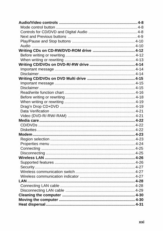
Audio/Video controls ........................................................................ 4-8Mode control button ........................................................................... 4-8Controls for CD/DVD and Digital Audio ............................................. 4-8Next and Previous buttons ................................................................ 4-9Play/Pause and Stop buttons .......................................................... 4-10Audio ...............................................................................................4-10
Writing CDs on CD-RW/DVD-ROM drive .......................................4-12Before writing or rewriting ................................................................ 4-12When writing or rewriting .................................................................4-13
Writing CD/DVDs on DVD-R/-RW drive ..........................................4-14Important message ..........................................................................4-14Disclaimer ........................................................................................ 4-14
Writing CD/DVDs on DVD Multi drive ............................................4-15Important message ..........................................................................4-15Disclaimer ........................................................................................ 4-15Read/write function chart .................................................................4-16Before writing or rewriting ................................................................ 4-18When writing or rewriting .................................................................4-19Drag’n Drop CD+DVD .....................................................................4-19Data Verification ..............................................................................4-21Video (DVD-R/-RW/-RAM) ..............................................................4-21
Media care ........................................................................................ 4-22CD/DVDs .........................................................................................4-22Diskettes ..........................................................................................4-22
Modem.............................................................................................. 4-23Region selection ..............................................................................4-23Properties menu ..............................................................................4-24Connecting ......................................................................................4-25Disconnecting .................................................................................. 4-25
Wireless LAN ...................................................................................4-26Supported features ..........................................................................4-26Security ............................................................................................4-27Wireless communication switch ....................................................... 4-27Wireless communication indicator ...................................................4-27
LAN ...................................................................................................4-28Connecting LAN cable .....................................................................4-28Disconnecting LAN cable ................................................................ 4-29
Cleaning the computer ................................................................... 4-30Moving the computer ...................................................................... 4-30Heat dispersal .................................................................................. 4-31

xxii
Chapter 5 The KeyboardTypewriter keys ................................................................................. 5-1F1 … F12 function keys .................................................................... 5-2Soft keys: Fn key combinations ....................................................... 5-2Emulating keys on enhanced keyboard ............................................. 5-2Hot keys ............................................................................................. 5-4Fn Sticky key ..................................................................................... 5-6
Windows special keys ...................................................................... 5-7Keypad overlay .................................................................................. 5-7Turning on the overlays ..................................................................... 5-7Temporarily using normal keyboard (overlay on) .............................. 5-8Temporarily using overlay (overlay off) .............................................. 5-9Temporarily changing modes ............................................................ 5-9
Generating ASCII characters ............................................................ 5-9
Chapter 6 PowerPower conditions .............................................................................. 6-1Power indicators ............................................................................... 6-2Battery indicator ................................................................................. 6-2DC IN indicator .................................................................................. 6-3Power indicator .................................................................................. 6-3
Battery types...................................................................................... 6-3Battery pack ....................................................................................... 6-3Real Time Clock battery .................................................................... 6-4
Care and use of the battery pack ..................................................... 6-5Safety precautions ............................................................................. 6-5Charging the batteries ....................................................................... 6-8Monitoring battery capacity ................................................................ 6-9Maximizing battery operating time ................................................... 6-10Retaining data with power off .......................................................... 6-11Extending battery life .......................................................................6-11
Replacing the battery pack ............................................................. 6-12Removing the battery pack ..............................................................6-12Installing the battery pack ................................................................ 6-13
TOSHIBA Password Utility ............................................................. 6-14User password................................................................................. 6-14Supervisor password .......................................................................6-16Starting the computer by password ................................................. 6-16
Power-up modes .............................................................................6-17Windows utilities .............................................................................. 6-18

xxiii
Hot keys ........................................................................................... 6-18Panel power on/off ..........................................................................6-18System Auto Off ..............................................................................6-18
Chapter 7 HW SetupAccessing HW Setup ........................................................................ 7-1HW Setup window .............................................................................7-1General .............................................................................................. 7-1Parallel/Printer ...................................................................................7-2Display ...............................................................................................7-2Boot Priority ....................................................................................... 7-2Keyboard ........................................................................................... 7-4CPU ................................................................................................... 7-4LAN.................................................................................................... 7-5
Chapter 8 Optional DevicesPC cards ............................................................................................. 8-2Inserting a PC card ............................................................................ 8-2Removing a PC card ......................................................................... 8-3
SD cards ............................................................................................. 8-4Inserting an SD card ..........................................................................8-4Removing an SD card .......................................................................8-5SD card care ......................................................................................8-5
Memory expansion ............................................................................ 8-6Installing memory module .................................................................. 8-7Removing memory module ................................................................ 8-8
Battery packs ..................................................................................... 8-9Universal AC adaptor ........................................................................ 8-9USB FDD kit ..................................................................................... 8-10External monitor ..............................................................................8-10TV......................................................................................................8-10Connecting a TV ..............................................................................8-10Changing the resolution ................................................................... 8-11
Parallel printer .................................................................................8-11i.LINK (IEEE1394) ........................................................................... 8-12Precautions ......................................................................................8-12Connecting ......................................................................................8-13Disconnecting .................................................................................. 8-13
Security lock ....................................................................................8-14

xxiv
Chapter 9 TroubleshootingProblem solving process .................................................................. 9-1Preliminary checklist .......................................................................... 9-1Analyzing the problem ....................................................................... 9-2
Hardware and system checklist ....................................................... 9-3System start-up ................................................................................. 9-3Self test .............................................................................................. 9-4Power ................................................................................................ 9-4Password ........................................................................................... 9-7Keyboard ........................................................................................... 9-8LCD panel .......................................................................................... 9-8Hard disk drive ................................................................................... 9-9CD-RW/DVD-ROM drive .................................................................9-10DVD-R/-RW drive ............................................................................ 9-11DVD Multi drive ................................................................................9-13Diskette drive ...................................................................................9-15SD card ............................................................................................9-15PC card ............................................................................................9-16Infrared port ..................................................................................... 9-16Pointing device ................................................................................9-17USB ................................................................................................. 9-19Memory expansion ..........................................................................9-19Sound system .................................................................................. 9-20Monitor ............................................................................................. 9-20Modem............................................................................................. 9-21LAN..................................................................................................9-22Wireless LAN ...................................................................................9-23TV output signal ............................................................................... 9-23Printer .............................................................................................. 9-24i.LINK (IEEE1394)........................................................................... 9-25
TOSHIBA support ............................................................................ 9-25Before you call ................................................................................. 9-25Where to write ................................................................................. 9-26
xxv
AppendixesAppendix ASpecifications ................................................................................... A-1
Appendix BDisplay Controller and Modes ......................................................... B-1
Appendix CAT Commands .................................................................................. C-1
Appendix DS-registers ........................................................................................ D-1
Appendix EV.90 .................................................................................................... E-1
Appendix FInternal Modem Guide ...................................................................... F-1
Appendix GWireless LAN .................................................................................... G-1
Appendix HAC Power Cord and Connectors ..................................................... H-1
Appendix IParts Numbers .................................................................................... I-1
Glossary
Index

xxvi
User's Manual
PrefaceCongratulations on your purchase of the Satellite M30 series computer. Thispowerful notebook computer provides excellent expansion capability, includingmultimedia devices, and it is designed to provide years of reliable, high-performancecomputing.
This manual tells how to set up and begin using your Satellite M30 series computer.It also provides detailed information on configuring your computer, basic opera-tions and care, using optional devices and troubleshooting.
If you are a new user of computers or if you’re new to portable computing, first readover the Introduction and The Grand Tour chapters to familiarize yourself with thecomputer’s features, components and accessory devices. Then read GettingStarted for step-by-step instructions on setting up your computer.
If you are an experienced computer user, please continue reading the preface tolearn how this manual is organized, then become acquainted with this manual bybrowsing through its pages. Be sure to look over the Special features section of theIntroduction, to learn about features that are uncommon or unique to the computersand carefully read HW Setup and Passwords.
Manual contentsThis manual is composed of nine chapters, nine appendixes, a glossary and anindex.
Chapter 1, Introduction, is an overview of the computer’s features, capabilities, andoptions.
Chapter 2, The Grand Tour, identifies the components of the computer and brieflyexplains how they function.
Chapter 3, Getting Started, provides a quick overview of how to begin operatingyour computer and gives tips on safety and designing your work area.
Chapter 4, Operating Basics, includes instructions on using the following devices:Touch Pad, USB diskette drive, optical media drives, audio/video controls, modem,wireless communication features, LAN. It also provides tips on care of the com-puter, diskettes and CD/DVDs.
Chapter 5, The Keyboard, describes special keyboard functions including thekeypad overlay and hot keys.

xxvii
Chapter 6, Power, gives details on the computer’s power resources and batterysave modes. It also tells how to set passwords.
Chapter 7, HW Setup, explains how to configure the computer using the HW Setupprogram.
Chapter 8, Optional Devices, describes the optional hardware available.
Chapter 9, Troubleshooting, suggests courses of action if the computer doesn’tseem to be working properly.
The Appendixes provide technical information about your computer.
The Glossary defines general computer terminology and includes a list of acronymsused in the text.
The Index quickly directs you to the information contained in this manual.
ConventionsThis manual uses the following formats to describe, identify, and highlight termsand operating procedures.
AbbreviationsOn first appearance, and whenever necessary for clarity, abbreviations are enclosedin parentheses following their definition. For example: Read Only Memory (ROM).Acronyms are also defined in the Glossary.
IconsIcons identify ports, dials, and other parts of your computer. The indicator panelalso uses icons to identify the components it is providing information on.
KeysThe keyboard keys are used in the text to describe many computer operations. Adistinctive typeface identifies the key top symbols as they appear on the keyboard.For example, Enter identifies the Enter key.
Conventions
xxviii
User's Manual
Key operationSome operations require you to simultaneously use two or more keys. We identifysuch operations by the key top symbols separated by a plus sign (+). For example,Ctrl + C means you must hold down Ctrl and at the same time press C. If threekeys are used, hold down the first two and at the same time press the third.
ABC When procedures require an action such as clicking an icon or enteringtext, the icon’s name or the text you are to type in is represented in thetype face you see to the left.
DisplayABC Names of windows or icons or text generated by the computer that
appears on its display screen is presented in the type face you see to theleft.
MessagesMessages are used in this manual to bring important information to your attention.Each type of message is identified as shown below.
CAUTION: Pay attention! A caution informs you that improper use ofequipment or failure to follow instructions may cause data loss ordamage your equipment.
NOTE: Please read. A note is a hint or advice that helps you make bestuse of your equipment.

xxix
General PrecautionsTOSHIBA computers are designed to optimize safety, minimize strain and withstandthe rigors of portability. However, certain precautions should be observed to furtherreduce the risk of personal injury, damage to the computer or impaired performance.
Be certain to read the general precautions below and to note the cautions includedin the text of the manual.
Stress injuryCarefully read the Instruction Manual for Safety & Comfort. It contains informationon prevention of stress injuries to your hands and wrists than can be caused byextensive keyboard use. Chapter 3, Getting Started, also includes information onwork space design, posture and lighting that can help reduce physical stress.
Heat injury❖❖❖❖❖ Avoid prolonged physical contact with the computer. If the computer is used
for long periods, its surface can become very warm. While the temperature willnot feel hot to the touch, if you maintain physical contact with the computer fora long time (if you rest the computer on your lap, or if you keep your hands onthe palm rest, for example) your skin might suffer low-heat injury.
❖❖❖❖❖ If the computer has been used for a long time, avoid direct contact with themetal plate supporting the I/O ports. It can become hot.
❖❖❖❖❖ The surface of the AC adaptor can become hot when in use. This conditiondoes not indicate a malfunction. If you need to transport the AC adaptor,disconnect it and let it cool before moving it.
❖❖❖❖❖ Do not lay the AC adaptor on a material that is sensitive to heat. The materialcould be damaged.
Pressure or impact damageDo not apply heavy pressure to the computer or subject it to strong impact.Excessive pressure or impact can cause damage to computer components orotherwise cause malfunctions.
User's Manual
xxx
PC card overheatingSome PC cards can become hot with prolonged use. Overheating of a PC card canresult in errors or instability in the PC card operation. Also be careful when youremove a PC card that has been used for a long time.
Mobile phoneUse of mobile phones can interfere with the audio system. Computer operation isnot impaired but it is recommended that a distance of 30 cm be maintained betweenthe computer and a mobile phone in use.
Central Processing Unit (CPU) PerformanceDisclaimerCPU performance in your computer product may vary from specifications under thefollowing conditions:
❖❖❖❖❖ Use of certain peripheral products
❖❖❖❖❖ Use of battery power instead of AC power
❖❖❖❖❖ Use of certain multimedia games or videos with special effects
❖❖❖❖❖ Use of standard telephone lines or low speed network connections
❖❖❖❖❖ Use of complex modeling software, such as high end computer aided designapplications
❖❖❖❖❖ Use of the computer in areas with low air pressure (high altitude > 1,000 metersor > 3,280 feet above sea level)
❖❖❖❖❖ Use of the computer at temperatures outside the range of 5°C to 35°C (41°F to95°F) or > 25°C (77°F) at high altitude (all temperature references are approxi-mate).
CPU performance may also vary from specifications due to design configuration.
Under some conditions, your computer product may automatically shut down. Thisis a normal protective feature designed to reduce the risk of lost data or damage tothe product when used outside recommended conditions. To avoid risk of lost data,always make back-up copies of data by periodically storing it on an external storagemedium. For optimum performance, use your computer product only under recom-mended conditions. Read additional restrictions under Environmental requirementsin Appendix A, Specifications. Contact TOSHIBA Technical Service and Supportfor more information.

1-1
INT
RO
DU
CT
ION
Chapter 1
IntroductionThis chapter provides an equipment checklist, and it identifies the computer’sfeatures, options and accessories.
CAUTION: Some of the features described in this manual might notfunction properly if you use an operating system that was not prein-stalled by TOSHIBA.
Equipment checklistCarefully unpack your computer. Save the box and packing materials for future use.
Hardware Check to make sure you have all the following items:
❖❖❖❖❖ Satellite M30 Series Portable Personal Computer
❖❖❖❖❖ Universal AC adaptor and power cord
❖❖❖❖❖ USB diskette drive (Provided with some models)
❖❖❖❖❖ Modular cable
Software❖❖❖❖❖ The following software is preinstalled:
• Microsoft® Windows XP Home Edition/Professional• Modem driver• Display Driver• TOSHIBA Utilities• Wireless LAN driver (Can be used only for Wireless LAN models)• Sound Driver• DVD-Video Player (Can be used only for DVD-ROM/Multi model)• LAN Drivers• Synaptics Pointing Device Driver• TOSHIBA Power Saver• TOSHIBA Console

1-2
User's ManualIN
TR
OD
UC
TIO
N • Infrared Device Driver• Online manual
❖❖❖❖❖ Product Recovery CD-ROM
Documentation• Satellite M30 Portable Personal Computer User's Manual• Microsoft Windows XP Home Edition/Professional manual package• Instruction Manual for Safety & Comfort• End User License Agreement
If any of the items are missing or damaged, contact your dealer immediately.
FeaturesThe computer uses TOSHIBA’s advanced Large Scale Integration (LSI), Comple-mentary Metal-Oxide Semiconductor (CMOS) technology extensively to providecompact size, minimum weight, low power usage, and high reliability. This computerincorporates the following features and benefits:
Processor
Built-in The computer is equipped with an Intel® Processor, whichincorporates a math co-processor, a 64 KB level 1 cachememory and a 1 MB level 2 cache memory. It also supportsEnhanced Intel® SpeedStep™ technology.
1.4 GHz Intel® Pentium® M processor 1.4 GHz1.5 GHz Intel® Pentium® M processor 1.5 GHz1.6 GHz Intel® Pentium® M processor 1.6 GHz1.7 GHz Intel® Pentium® M processor 1.7 GHz
NOTE: Some models of the computers carry Intel® CentrinoTM technol-ogy, which is based on three separate technologies of Intel® Pentium®M, Intel® PRO/Wireless Network Connection, and Intel® 855 ChipsetFamily.
Memory
Slots 256, 512 MB or 1 GB memory modules can be installed inthe two memory slots for a maximum of 2 GB systemmemory.
Video RAM 32 or 64 MB of RAM is provided for video display.
1-3
INT
RO
DU
CT
ION
Power
Battery pack The computer is powered by one rechargeable lithium-ionbattery pack.
RTC battery The computer has an internal battery to back up theinternal Real Time Clock (RTC) and calendar.
Universal AC adaptor The universal AC adaptor provides power to the systemand recharges the batteries when they are low. It comeswith a detachable power cord.
Because it is universal, it can receive a range of ACvoltage from 100 to 240 volts; however, the output currentvaries among different models. Using the wrong model candamage your computer. Refer to the Universal AC adaptorsection in Chapter 2, The Grand Tour.
Disks
Hard disk drive Available in three sizes.• 37.26 GB (40.0 billion bytes)• 55.89 GB (60.0 billion bytes)• 74.53 GB (80.0 billion bytes)
USB diskette drive Accommodates either 3 1/2" 1.44-megabyte or 720-kilobytediskettes. It connects to a USB port. It is an option withsome models.
Optical media drive The computer is configured with one of the optical mediadrives listed below. Refer also to Chapter 2, The GrandTour, for specifications and to Chapter 4, OperatingBasics, for information on using the drives.
CD-RW/DVD-ROM drive
A full-size, CD-RW/DVD-ROM drive module lets you runCD/DVDs without using an adaptor. It reads DVD-ROMsat maximum 8 speed and CD-ROMs at maximum 24 speed.It writes CD-R and CD-RW at up to 24 speed. A ModeControl button turns power to the CD-RW/DVD-ROMdrive on and off so you can use the drive as a stand-aloneaudio CD player.
Features

1-4
User's ManualIN
TR
OD
UC
TIO
N DVD-R/-RW drive
A full-size DVD-R/-RW drive module lets you record datato rewritable CD/DVDs as well as run either 12 cm (4.72") or8 cm (3.15") CD/DVDs without using an adaptor. It readsDVD-ROMs at maximum 8 speed and CD-ROMs atmaximum 24 speed. It writes CD-R at up to 16 speed, CD-RW at up to 10 speed, DVD-R and DVD-RW at singlespeed.
DVD Multi drive
A full-size, DVD Multi drive module lets you run either 12cm (4.72") or 8 cm (3.15") CD/DVDs without using anadaptor. It reads DVD-ROMs at maximum 8 speed and CD-ROMs at maximum 24 speed. It writes CD-R at up to 16speed, CD-RW at up to 8 speed, DVD-R and DVD-RAM at2 speed, and DVD-RW at single speed.
Display
The computer’s LCD panel supports high-resolution video graphics. The screencan be set at a wide range of viewing angles for maximum comfort and readability.
Built-in 15.4" TFT screen, 16 M colors, with a resolution of 1280horizontal x 800 vertical pixels WXGA.
Graphics controller A 128-bit graphics controller maximizes display perfor-mance. Refer to Appendix B for more information.
Keyboard
Built-in 85 keys or 86 keys, compatible with IBM® enhancedkeyboard, embedded numeric overlay, dedicated cursorcontrol, and keys. Refer to Chapter 5, The Key-board, for details.
Pointing device
Built-in Touch Pad A Touch Pad and control buttons in the palm rest enablecontrol of the on-screen pointer and scrolling of windows.
1-5
INT
RO
DU
CT
ION
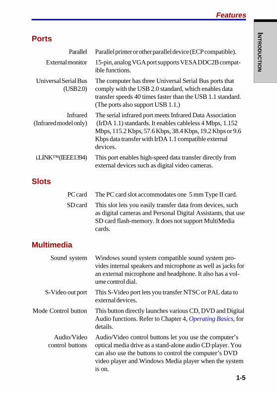
Ports
Parallel Parallel printer or other parallel device (ECP compatible).
External monitor 15-pin, analog VGA port supports VESA DDC2B compat-ible functions.
Universal Serial Bus The computer has three Universal Serial Bus ports that(USB 2.0) comply with the USB 2.0 standard, which enables data
transfer speeds 40 times faster than the USB 1.1 standard.(The ports also support USB 1.1.)
Infrared The serial infrared port meets Infrared Data Association(Infrared model only) (IrDA 1.1) standards. It enables cableless 4 Mbps, 1.152
Mbps, 115.2 Kbps, 57.6 Kbps, 38.4 Kbps, 19.2 Kbps or 9.6Kbps data transfer with IrDA 1.1 compatible externaldevices.
i.LINK™ (IEEE1394) This port enables high-speed data transfer directly fromexternal devices such as digital video cameras.
Slots
PC card The PC card slot accommodates one 5 mm Type II card.
SD card This slot lets you easily transfer data from devices, suchas digital cameras and Personal Digital Assistants, that useSD card flash-memory. It does not support MultiMediacards.
Multimedia
Sound system Windows sound system compatible sound system pro-vides internal speakers and microphone as well as jacks foran external microphone and headphone. It also has a vol-ume control dial.
S-Video out port This S-Video port lets you transfer NTSC or PAL data toexternal devices.
Mode Control button This button directly launches various CD, DVD and DigitalAudio functions. Refer to Chapter 4, Operating Basics, fordetails.
Audio/Video Audio/Video control buttons let you use the computer’s control buttons optical media drive as a stand-alone audio CD player. You
can also use the buttons to control the computer’s DVDvideo player and Windows Media player when the systemis on.
Features
1-6
User's ManualIN
TR
OD
UC
TIO
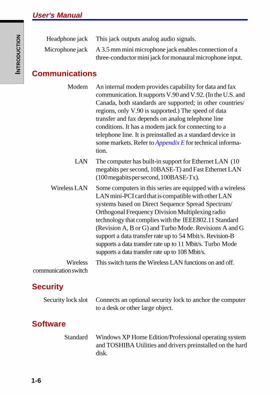
N Headphone jack This jack outputs analog audio signals.
Microphone jack A 3.5 mm mini microphone jack enables connection of athree-conductor mini jack for monaural microphone input.
Communications
Modem An internal modem provides capability for data and faxcommunication. It supports V.90 and V.92. (In the U.S. andCanada, both standards are supported; in other countries/regions, only V.90 is supported.) The speed of datatransfer and fax depends on analog telephone lineconditions. It has a modem jack for connecting to atelephone line. It is preinstalled as a standard device insome markets. Refer to Appendix E for technical informa-tion.
LAN The computer has built-in support for Ethernet LAN (10megabits per second, 10BASE-T) and Fast Ethernet LAN(100 megabits per second, 100BASE-Tx).
Wireless LAN Some computers in this series are equipped with a wirelessLAN mini-PCI card that is compatible with other LANsystems based on Direct Sequence Spread Spectrum/Orthogonal Frequency Division Multiplexing radiotechnology that complies with the IEEE802.11 Standard(Revision A, B or G) and Turbo Mode. Revisions A and Gsupport a data transfer rate up to 54 Mbit/s. Revision-Bsupports a data transfer rate up to 11 Mbit/s. Turbo Modesupports a data transfer rate up to 108 Mbit/s.
Wireless This switch turns the Wireless LAN functions on and off. communication switch
Security
Security lock slot Connects an optional security lock to anchor the computerto a desk or other large object.
Software
Standard Windows XP Home Edition/Professional operating systemand TOSHIBA Utilities and drivers preinstalled on the harddisk.
1-7
INT
RO
DU
CT
ION
Special features
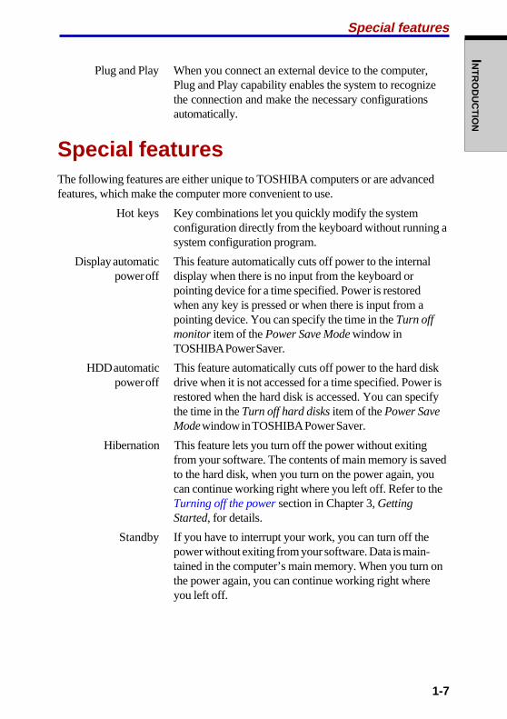
Plug and Play When you connect an external device to the computer,Plug and Play capability enables the system to recognizethe connection and make the necessary configurationsautomatically.
Special featuresThe following features are either unique to TOSHIBA computers or are advancedfeatures, which make the computer more convenient to use.
Hot keys Key combinations let you quickly modify the systemconfiguration directly from the keyboard without running asystem configuration program.
Display automatic This feature automatically cuts off power to the internalpower off display when there is no input from the keyboard or
pointing device for a time specified. Power is restoredwhen any key is pressed or when there is input from apointing device. You can specify the time in the Turn offmonitor item of the Power Save Mode window inTOSHIBA Power Saver.
HDD automatic This feature automatically cuts off power to the hard diskpower off drive when it is not accessed for a time specified. Power is
restored when the hard disk is accessed. You can specifythe time in the Turn off hard disks item of the Power SaveMode window in TOSHIBA Power Saver.
Hibernation This feature lets you turn off the power without exitingfrom your software. The contents of main memory is savedto the hard disk, when you turn on the power again, youcan continue working right where you left off. Refer to theTurning off the power section in Chapter 3, GettingStarted, for details.
Standby If you have to interrupt your work, you can turn off thepower without exiting from your software. Data is main-tained in the computer’s main memory. When you turn onthe power again, you can continue working right whereyou left off.

1-8
User's ManualIN
TR
OD
UC
TIO
N System automatic This feature automatically shuts down the system inStandby/Hibernation standby mode or Hibernation mode when there is no input
or hardware access for a time specified. You can specifythe time and select either System Standby or SystemHibernate in the System standby and System hibernateitem of the Power Save Mode window in TOSHIBA PowerSaver.
Keypad overlay A ten-key pad is integrated into the keyboard. Refer to theKeypad overlay section in Chapter 5, The Keyboard, forinstructions on using the keypad overlay.
Power on password Two levels of password security, supervisor and user, areavailable to prevent unauthorized access to your computer.
Instant security A hot key function blanks the screen and disables thecomputer providing data security.
Intelligent A microprocessor in the computer’s intelligent powerpower supply supply detects the battery’s charge and calculates the
remaining battery capacity. It also protects electroniccomponents from abnormal conditions, such as voltageoverload from a universal AC adaptor. You can monitorremaining battery capacity. Use the Battery remaining itemof the Power Save Modes window in TOSHIBA PowerSaver.
Battery save mode This feature lets you save battery power. You can specifythe Power Save Mode in the Running on batteries item ofthe Power Save Modes window in TOSHIBA Power Saver.
Panel power on/off This feature turns power to the computer off when thedisplay panel is closed and turns it back on when the panelis opened. You can specify the setting in the When I closethe lid item of the System Power Mode window inTOSHIBA Power Saver.
Low battery When battery power is exhausted to the point thatautomatic hibernation computer operation cannot be continued, the system
automatically enters Hibernation and shuts down. You canspecify the setting in the Battery Alarm item of the Alarmwindow in TOSHIBA Power Saver.
Heat dispersal The CPU has an internal temperature sensor that automati-cally activates cooling procedures. Refer to the Heatdispersal section in Chapter 4, Operating Basics, fordetails on setting the options for cooling methods.

1-9
INT
RO
DU
CT
ION
UtilitiesThis section describes preinstalled utilities and tells how to start them. For detailson operations, refer to each utility’s online manual, help files or readme files.
TOSHIBA Power Saver To access this power savings management program, openthe Control Panel and select the TOSHIBA Power Savericon.
HW Setup This program lets you customize your hardware settingsaccording to the way you work with your computer andthe peripherals you use. To start the utility, click theWindows Start button and click Control Panel. In theControl Panel, select the TOSHIBA HW Setup icon.
TOSHIBA Controls This utility has two sections to let you do the following:• Buttons: Assign applications to the Internet button
(default setting is the browser) and to the TOSHIBAConsole button (default setting is the TOSHIBAConsole).
• Media Apps: Set the mode for the Audio/Video controlbuttons. Select the application for audio and videoplayback.
Fn-esse This Windows program lets you define your own “short-cut” keys to quickly launch applications and speed yourwork in Windows. To start the utility, click the WindowsStart button, point to All Programs, point to TOSHIBA,point to Utilities and click Fn-esse.
DVD Video Player The DVD Video Player is used to play DVD-Video. It hasan on-screen interface and functions. Click Start, point toAll Programs, point to InterVideo WinDVD 4, then clickInterVideo WinDVD 4.
ConfigFree ConfigFree is a suite of utilities to allow easy control ofcommunication devices and network connections.ConfigFree also allows you to find communicationproblems and create profiles for easy switching betweenlocations and communication networks. To start Config-Free, click the Windows Start button, point to All Pro-grams, point to TOSHIBA, point to Networking and clickConfigFree.
Utilities
1-10
User's ManualIN
TR
OD
UC
TIO
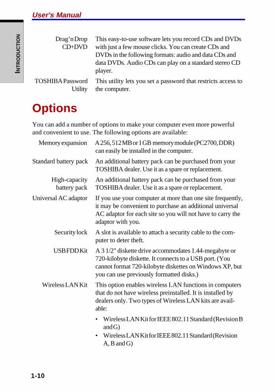
N Drag’n Drop This easy-to-use software lets you record CDs and DVDs CD+DVD with just a few mouse clicks. You can create CDs and
DVDs in the following formats: audio and data CDs anddata DVDs. Audio CDs can play on a standard stereo CDplayer.
TOSHIBA Password This utility lets you set a password that restricts access toUtility the computer.
OptionsYou can add a number of options to make your computer even more powerfuland convenient to use. The following options are available:
Memory expansion A 256, 512 MB or 1 GB memory module (PC2700, DDR)can easily be installed in the computer.
Standard battery pack An additional battery pack can be purchased from yourTOSHIBA dealer. Use it as a spare or replacement.
High-capacity An additional battery pack can be purchased from your battery pack TOSHIBA dealer. Use it as a spare or replacement.
Universal AC adaptor If you use your computer at more than one site frequently,it may be convenient to purchase an additional universalAC adaptor for each site so you will not have to carry theadaptor with you.
Security lock A slot is available to attach a security cable to the com-puter to deter theft.
USB FDD Kit A 3 1/2" diskette drive accommodates 1.44-megabyte or720-kilobyte diskette. It connects to a USB port. (Youcannot format 720-kilobyte diskettes on Windows XP, butyou can use previously formatted disks.)
Wireless LAN Kit This option enables wireless LAN functions in computersthat do not have wireless preinstalled. It is installed bydealers only. Two types of Wireless LAN kits are avail-able:
• Wireless LAN Kit for IEEE 802.11 Standard (Revision Band G)
• Wireless LAN Kit for IEEE 802.11 Standard (RevisionA, B and G)
TH
E GR
AN
D TO
UR
2-1
Chapter 2
The Grand TourThis chapter identifies the various components of your computer. Become familiarwith each component before you operate the computer.
Front with the display closedFigure 2-1 shows the computer’s front with its display panel in the closed position.
INDICATORS (1) MODE CONTROL AUDIO/VIDEO INDICATORS (2) DISPLAY LATCH
BUTTON CONTROL BUTTONS
INFRARED PORT WIRELESS COMMUNICATION SWITCH VOLUME CONTROL
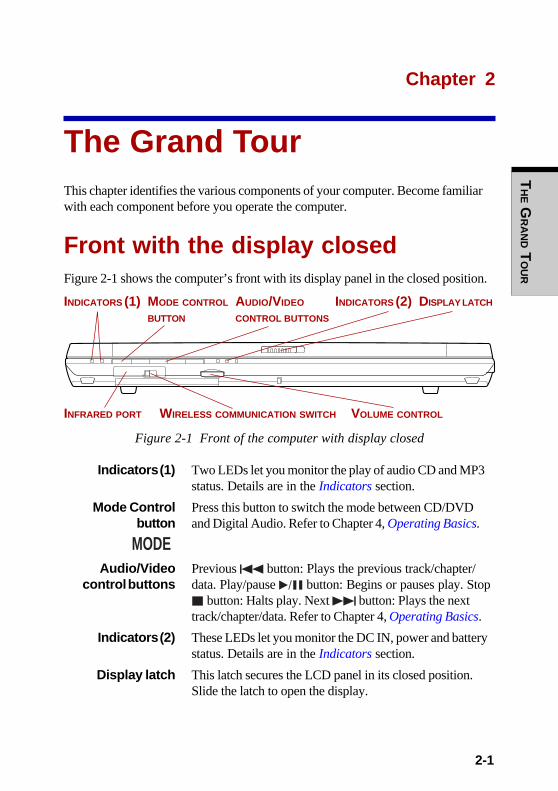
Figure 2-1 Front of the computer with display closed
Indicators (1) Two LEDs let you monitor the play of audio CD and MP3status. Details are in the Indicators section.
Mode Control Press this button to switch the mode between CD/DVDbutton and Digital Audio. Refer to Chapter 4, Operating Basics.
Audio/Video Previous button: Plays the previous track/chapter/ control buttons data. Play/pause button: Begins or pauses play. Stop
button: Halts play. Next button: Plays the nexttrack/chapter/data. Refer to Chapter 4, Operating Basics.
Indicators (2) These LEDs let you monitor the DC IN, power and batterystatus. Details are in the Indicators section.
Display latch This latch secures the LCD panel in its closed position.Slide the latch to open the display.
MODE
User's ManualT
HE G
RA
ND T
OU
R
2-2
Infrared port This infrared port is compatible with Infrared Data Asso-(Infrared model ciation (IrDA 1.1) standards. It enables cableless 4 Mbps,
only) 1.15 Mbps, 115.2 Kbps, 57.6 Kbps, 38.4 Kbps, 19.2 Kbps or9.6 Kbps data transfer with IrDA 1.1 compatible externaldevices.
Volume control Use this dial to adjust the volume of the stereo speakers orthe stereo headphones.
Wireless This switch turns the Wireless functions on and off. Communication
switch
CAUTION: Set the switch to off in airplanes and hospitals. Check thewireless communication indicator. It will stop glowing when the wirelesscommunication function is off.
Left sideFigure 2-2 shows the computer’s left side.
SECURITY LOCK COOLING VENTS PARALLEL PORT PC CARD SLOT
S-VIDEO OUT PORT I.LINK (IEEE1394) PORT SD CARD SLOT
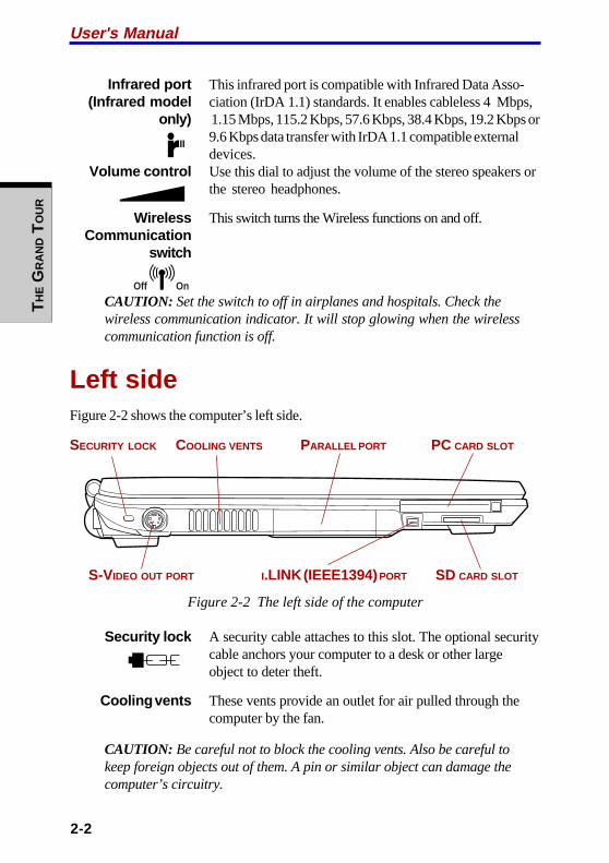
Figure 2-2 The left side of the computer
Security lock A security cable attaches to this slot. The optional securitycable anchors your computer to a desk or other largeobject to deter theft.
Cooling vents These vents provide an outlet for air pulled through thecomputer by the fan.
CAUTION: Be careful not to block the cooling vents. Also be careful tokeep foreign objects out of them. A pin or similar object can damage thecomputer’s circuitry.
Off On
TH
E GR
AN
D TO
UR
2-3
Right side
Parallel port This Centronics-compatible, 25-pin parallel port is used toconnect a parallel printer or other parallel device. This portsupports Extended Capabilities Port (ECP) standard.
PC card slot A PC card slot can accommodate one 5 mm Type II card.You can install any industry standard PC card such as aSCSI adaptor, Ethernet adaptor or flash memory card.
CAUTION: Keep foreign objects out of the PC card slot. A pin or similarobject can damage the computer’s circuitry.
S-Video out port This S-Video port lets you transfer NTSC or PAL data toexternal devices.
i.LINK (IEEE1394) Connect an external device, such as a digital video cameraport to this port for high-speed data transfer.
SD card slot SD cards are used in a wide variety of external devices.This slot lets you transfer data from the device to yourcomputer. An indicator on the right side of the slot glowswhen a card is being accessed.
CAUTION: Keep foreign objects out of the SD card slot. A pin or similarobject can damage the computer’s circuitry.
Right sideFigure 2-3 shows the computer’s right side.
HEADPHONE JACK MICROPHONE JACK
USB PORTS OPTICAL MEDIA DRIVE USB PORT
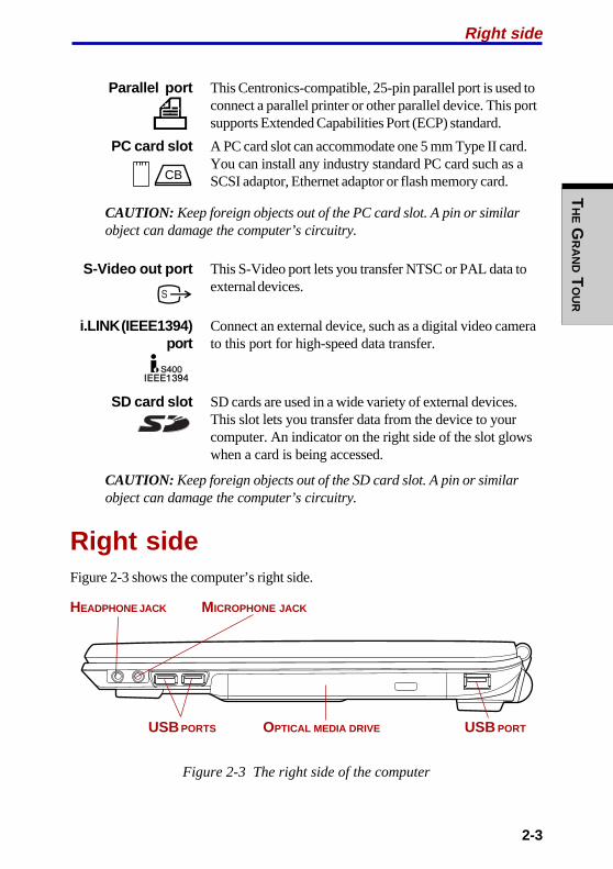
Figure 2-3 The right side of the computer
CB
User's ManualT
HE G
RA
ND T
OU
R
2-4
Headphone jack This jack lets you connect digital speakers or a stereoheadphone (16 ohm minimum). When you connect a digitalspeaker or headphones, the internal speaker is automati-cally disabled.
Microphone jack A 3.5 mm mini microphone jack enables connection of athree-conductor mini jack for monaural microphone input.
Optical media The computer is configured with a CD-RW/DVD-ROMdrive drive, DVD-R/-RW drive or a DVD Multi drive.
Universal Three Universal Serial Bus ports comply with the USB 2.0Serial Bus standard, which enables data transfer speeds 40 times
(USB 2.0) ports faster than the USB 1.1 standard. (The ports also supportUSB 1.1.)
CAUTION: Keep foreign objects out of the USB connectors. A pin orsimilar object can damage the computer’s circuitry.
NOTE: Operation of all functions of all USB devices has not beenconfirmed. Some functions might not execute properly.
Back sideFigure 2-4 shows the computer’s back side.
LAN ACTIVE LAN JACK LINK INDICATOR EXTERNAL MONITOR PORT
INDICATOR (GREEN)(ORANGE)
DC IN 15V MODEM JACK BATTERY PACK
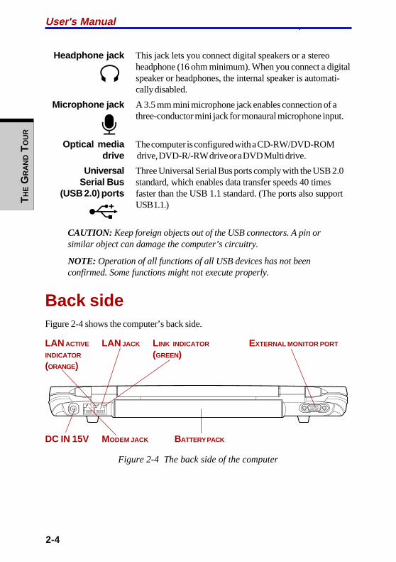
Figure 2-4 The back side of the computer
.
TH
E GR
AN
D TO
UR
2-5
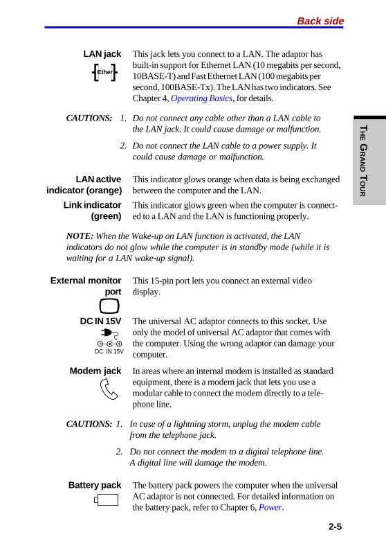
LAN jack This jack lets you connect to a LAN. The adaptor hasbuilt-in support for Ethernet LAN (10 megabits per second,10BASE-T) and Fast Ethernet LAN (100 megabits persecond, 100BASE-Tx). The LAN has two indicators. SeeChapter 4, Operating Basics, for details.
CAUTIONS: 1. Do not connect any cable other than a LAN cable tothe LAN jack. It could cause damage or malfunction.
2. Do not connect the LAN cable to a power supply. Itcould cause damage or malfunction.
LAN active This indicator glows orange when data is being exchanged indicator (orange) between the computer and the LAN.
Link indicator This indicator glows green when the computer is connect- (green) ed to a LAN and the LAN is functioning properly.
NOTE: When the Wake-up on LAN function is activated, the LANindicators do not glow while the computer is in standby mode (while it iswaiting for a LAN wake-up signal).
External monitor This 15-pin port lets you connect an external videoport display.
DC IN 15V The universal AC adaptor connects to this socket. Useonly the model of universal AC adaptor that comes withthe computer. Using the wrong adaptor can damage yourcomputer.
Modem jack In areas where an internal modem is installed as standardequipment, there is a modem jack that lets you use amodular cable to connect the modem directly to a tele-phone line.
CAUTIONS: 1. In case of a lightning storm, unplug the modem cablefrom the telephone jack.
2. Do not connect the modem to a digital telephone line.A digital line will damage the modem.
Battery pack The battery pack powers the computer when the universalAC adaptor is not connected. For detailed information onthe battery pack, refer to Chapter 6, Power.
Back side
Ether
DC IN 15V
User's ManualT
HE G
RA
ND T
OU
R
2-6
UndersideFigure 2-5 shows the underside of the computer. Make sure the display is closedbefore turning over your computer.
BATTERY RELEASE LATCH BATTERY SAFETY LOCK
MEMORY MODULE COVER
Figure 2-5 The underside of the computer
Memory module This cover protects two memory module sockets. One or cover two modules are preinstalled. Refer to the Memory
expansion section in Chapter 8, Optional Devices.
Battery release Slide this latch to release the battery pack for removal.latch
Battery safety lock Slide the battery safety lock forward to free the batterylatch.
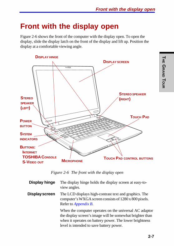
TH
E GR
AN
D TO
UR
2-7
Front with the display openFigure 2-6 shows the front of the computer with the display open. To open thedisplay, slide the display latch on the front of the display and lift up. Position thedisplay at a comfortable viewing angle.
Figure 2-6 The front with the display open
Display hinge The display hinge holds the display screen at easy-to-view angles.
Display screen The LCD displays high-contrast text and graphics. Thecomputer’s WXGA screen consists of 1280 x 800 pixels.Refer to Appendix B.
When the computer operates on the universal AC adaptorthe display screen’s image will be somewhat brighter thanwhen it operates on battery power. The lower brightnesslevel is intended to save battery power.
Front with the display open
TOUCH PAD CONTROL BUTTONS
TOUCH PAD
DISPLAY HINGE
DISPLAY SCREEN
STEREO
SPEAKER
(LEFT)
STEREO SPEAKER
(RIGHT)
POWER
BUTTON
SYSTEM
INDICATORS
BUTTONS:INTERNET
TOSHIBA CONSOLE
S-VIDEO OUT MICROPHONE
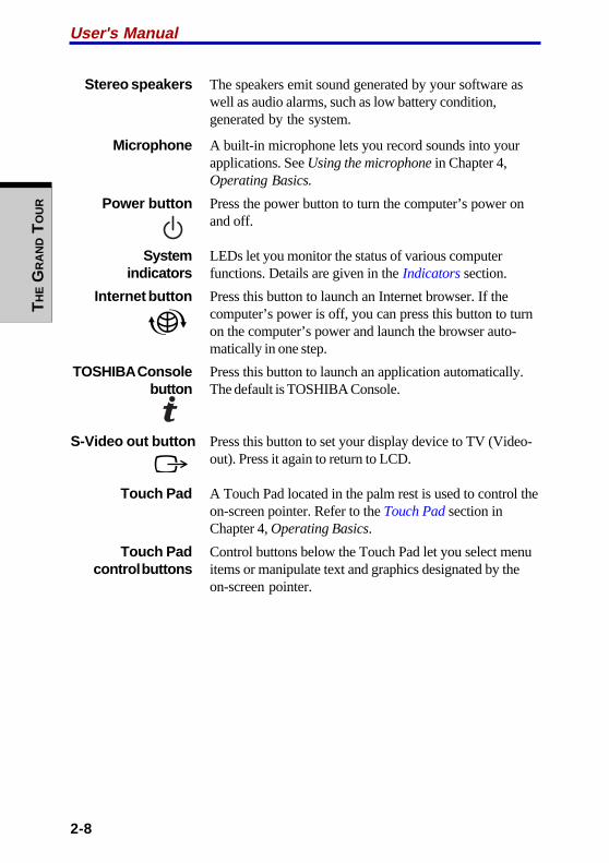
User's ManualT
HE G
RA
ND T
OU
R
2-8
Stereo speakers The speakers emit sound generated by your software aswell as audio alarms, such as low battery condition,generated by the system.
Microphone A built-in microphone lets you record sounds into yourapplications. See Using the microphone in Chapter 4,Operating Basics.
Power button Press the power button to turn the computer’s power onand off.
System LEDs let you monitor the status of various computerindicators functions. Details are given in the Indicators section.
Internet button Press this button to launch an Internet browser. If thecomputer’s power is off, you can press this button to turnon the computer’s power and launch the browser auto-matically in one step.
TOSHIBA Console Press this button to launch an application automatically.button The default is TOSHIBA Console.
S-Video out button Press this button to set your display device to TV (Video-out). Press it again to return to LCD.
Touch Pad A Touch Pad located in the palm rest is used to control theon-screen pointer. Refer to the Touch Pad section inChapter 4, Operating Basics.
Touch Pad Control buttons below the Touch Pad let you select menucontrol buttons items or manipulate text and graphics designated by the
on-screen pointer.

TH
E GR
AN
D TO
UR
2-9
Indicators
IndicatorsThe following indicators on the front of the computer can be monitored even whenthe display panel is closed.
CD/DVD DIGITAL AUDIO DC IN POWER BATTERY
Figure 2-7 System indicators
CD/DVD The CD/DVD indicator glows blue when the computer isaccessing a CD/DVD. Refer to Chapter 4, OperatingBasics, for details.
Digital Audio The Digital Audio indicator glows blue when reproduc-ing music files, such as WAVE, MIDI and MP3. Refer toChapter 4, Operating Basics, for details.
DC IN The DC IN indicator glows blue when DC power issupplied from the AC power adaptor. If the adaptor’soutput voltage is abnormal or if the power supply malfunc-tions, this indicator flashes orange.
Power The Power indicator glows blue when the computer is on.If you select Standby from Shut Down Windows ,this indicator flashes orange (one second on, two secondsoff) while the computer shuts down.
Battery The Battery indicator shows the condition of thebattery’s charge: Blue indicates full charge, orangeindicates battery charging and flashing orange indicates alow battery charge. Refer to Chapter 6, Power.
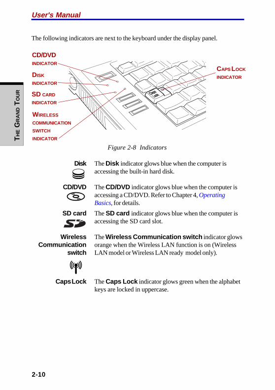
User's ManualT
HE G
RA
ND T
OU
R
2-10
The following indicators are next to the keyboard under the display panel.
Figure 2-8 Indicators
Disk The Disk indicator glows blue when the computer isaccessing the built-in hard disk.
CD/DVD The CD/DVD indicator glows blue when the computer isaccessing a CD/DVD. Refer to Chapter 4, OperatingBasics, for details.
SD card The SD card indicator glows blue when the computer isaccessing the SD card slot.
Wireless The Wireless Communication switch indicator glowsCommunication orange when the Wireless LAN function is on (Wireless
switch LAN model or Wireless LAN ready model only).
Caps Lock The Caps Lock indicator glows green when the alphabetkeys are locked in uppercase.
CAPS LOCK
INDICATOR
WIRELESS
COMMUNICATION
SWITCH
INDICATOR
DISK
INDICATOR
CD/DVDINDICATOR
SD CARD
INDICATOR
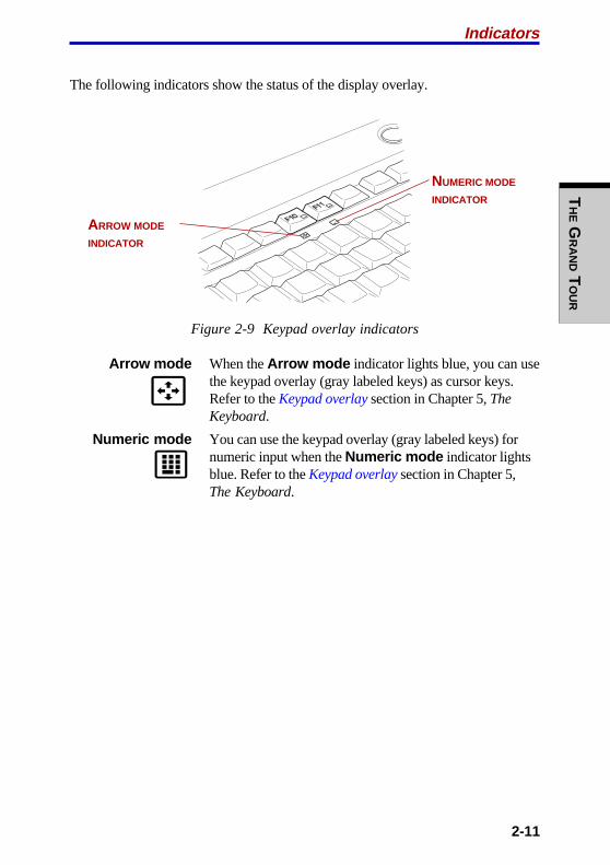
TH
E GR
AN
D TO
UR
2-11
The following indicators show the status of the display overlay.
Figure 2-9 Keypad overlay indicators
Arrow mode When the Arrow mode indicator lights blue, you can usethe keypad overlay (gray labeled keys) as cursor keys.Refer to the Keypad overlay section in Chapter 5, TheKeyboard.
Numeric mode You can use the keypad overlay (gray labeled keys) fornumeric input when the Numeric mode indicator lightsblue. Refer to the Keypad overlay section in Chapter 5,The Keyboard.
Indicators
ARROW MODE
INDICATOR
NUMERIC MODE
INDICATOR
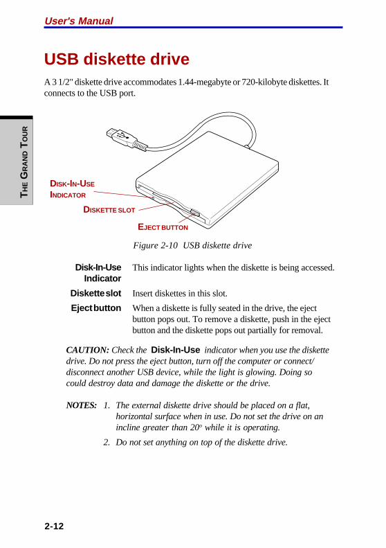
User's ManualT
HE G
RA
ND T
OU
R
2-12
USB diskette driveA 3 1/2" diskette drive accommodates 1.44-megabyte or 720-kilobyte diskettes. Itconnects to the USB port.
Figure 2-10 USB diskette drive
Disk-In-Use This indicator lights when the diskette is being accessed.Indicator
Diskette slot Insert diskettes in this slot.
Eject button When a diskette is fully seated in the drive, the ejectbutton pops out. To remove a diskette, push in the ejectbutton and the diskette pops out partially for removal.
CAUTION: Check the Disk-In-Use indicator when you use the diskettedrive. Do not press the eject button, turn off the computer or connect/disconnect another USB device, while the light is glowing. Doing socould destroy data and damage the diskette or the drive.
NOTES: 1. The external diskette drive should be placed on a flat,horizontal surface when in use. Do not set the drive on anincline greater than 20o while it is operating.
2. Do not set anything on top of the diskette drive.
DISK-IN-USE
INDICATOR
DISKETTE SLOT
EJECT BUTTON

TH
E GR
AN
D TO
UR
2-13
Optical media drivesOne of the following optical media drives is installed in the computer: CD-RW/DVD-ROM drive, DVD-R/-RW drive or DVD Multi drive. An ATAPI interface controlleris used for CD/DVD-ROM operation. When the computer is accessing a CD/DVD,an indicator on the drive glows.
For information on loading and unloading discs and on the Mode Control buttonsrefer to the Using optical media drives and Audio/Video controls section inChapter 4, Operating Basics.
Region codes for DVD drives and mediaCD-RW/DVD-ROM, DVD-R/-RW, DVD Multi drives and media are manufacturedaccording to the specifications of six marketing regions. When you purchase DVD-Video, make sure it matches your drive, otherwise it will not play properly.
Code Region
1 Canada, United States2 Japan, Europe, South Africa, Middle East3 Southeast Asia, East Asia4 Australia, New Zealand, Pacific Islands, Central America, South
America, Caribbean5 Russia, Indian Subcontinent, Africa, North Korea, Mongolia6 China
Writable discsThis section describes the types of writable CD/DVD discs. Check the specifica-tions for your drive to for the type of discs it can write. Use Drag’n Drop CD+DVDto write compact discs. Refer to Chapter 4, Operating Basics.
CDs
❖❖❖❖❖ CD-R discs can be written only once. The recorded data cannot be erased orchanged.
❖❖❖❖❖ CD-RW discs can be recorded more than once. Use either 1, 2, or 4 multi speedCD-RW discs or high-speed 4- to 10-speed discs. The write speed of the ultra-speed CD-RW discs is maximum 24-speed.
Optical media drives
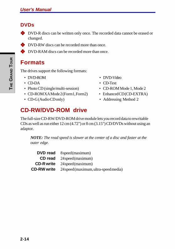
User's ManualT
HE G
RA
ND T
OU
R
2-14
DVDs
❖❖❖❖❖ DVD-R discs can be written only once. The recorded data cannot be erased orchanged.
❖❖❖❖❖ DVD-RW discs can be recorded more than once.
❖❖❖❖❖ DVD-RAM discs can be recorded more than once.
FormatsThe drives support the following formats:
• DVD-ROM • DVD-Video• CD-DA • CD-Text• Photo CD (single/multi-session) • CD-ROM Mode 1, Mode 2• CD-ROM XA Mode 2 (Form1, Form2) • Enhanced CD (CD-EXTRA)• CD-G (Audio CD only) • Addressing Method 2
CD-RW/DVD-ROM driveThe full-size CD-RW/DVD-ROM drive module lets you record data to rewritableCDs as well as run either 12 cm (4.72") or 8 cm (3.15") CD/DVDs without using anadaptor.
NOTE: The read speed is slower at the center of a disc and faster at theouter edge.
DVD read 8 speed (maximum)CD read 24 speed (maximum)
CD-R write 24 speed (maximum)CD-RW write 24 speed (maximum, ultra-speed media)
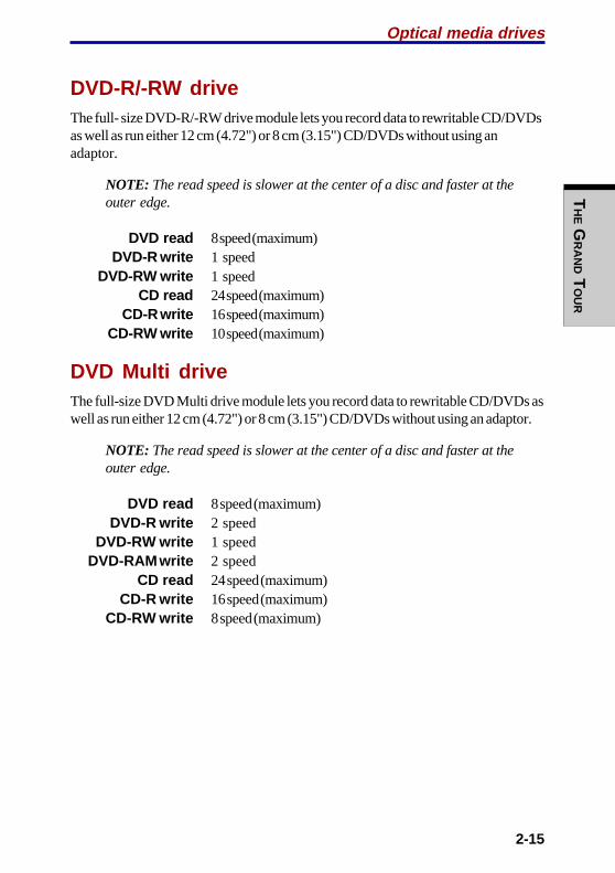
TH
E GR
AN
D TO
UR
2-15
DVD-R/-RW driveThe full- size DVD-R/-RW drive module lets you record data to rewritable CD/DVDsas well as run either 12 cm (4.72") or 8 cm (3.15") CD/DVDs without using anadaptor.
NOTE: The read speed is slower at the center of a disc and faster at theouter edge.
DVD read 8 speed (maximum)DVD-R write 1 speed
DVD-RW write 1 speedCD read 24 speed (maximum)
CD-R write 16 speed (maximum)CD-RW write 10 speed (maximum)
DVD Multi driveThe full-size DVD Multi drive module lets you record data to rewritable CD/DVDs aswell as run either 12 cm (4.72") or 8 cm (3.15") CD/DVDs without using an adaptor.
NOTE: The read speed is slower at the center of a disc and faster at theouter edge.
DVD read 8 speed (maximum)DVD-R write 2 speed
DVD-RW write 1 speedDVD-RAM write 2 speed
CD read 24 speed (maximum)CD-R write 16 speed (maximum)
CD-RW write 8 speed (maximum)
Optical media drives

User's ManualT
HE G
RA
ND T
OU
R
2-16
Universal AC adaptorThe universal AC adaptor converts AC power to DC power and reduces the voltagesupplied to the computer. It can automatically adjust to any voltage from 100 to 240volts and to a frequency of either 50 or 60 hertz, enabling you to use the computer inalmost any country/region.
To recharge the battery, simply connect the universal AC adaptor to a power sourceand the computer. Refer to Chapter 6, Power, for details.
Figure 2-11 The universal AC adaptor
CAUTION: Use only the universal AC adaptor that came with thecomputer or an equivalent optional adaptor. Use of the wrong adaptorcould damage your computer. TOSHIBA assumes no liability for anydamage in such case.
3-1
GE
TT
ING S
TA
RT
ED
Chapter 3
Getting StartedThis chapter provides basic information to get you started using your computer. Itcovers the following topics:
❖❖❖❖❖ Setting up your work space — for your health and safety
NOTE: Be sure also to read Instruction Manual for Safety & Comfort.This guide, which is included with the computer, explains productliability.
❖❖❖❖❖ Connecting the universal AC adaptor
❖❖❖❖❖ Opening the display
❖❖❖❖❖ Turning on the power
❖❖❖❖❖ Starting up for the first time
❖❖❖❖❖ Turning off the power
❖❖❖❖❖ Restarting the computer
❖❖❖❖❖ Restoring the preinstalled software
NOTE: All users should be sure to read the section Starting up for thefirst time.
Setting up your work spaceEstablishing a comfortable work site is important for you and your computer. Apoor work environment or stressful work habits can result in discomfort or seriousinjury from repetitive strain to your hands, wrists or other joints. Proper ambientconditions should also be maintained for the computer’s operation. This sectiondiscusses the following topics:
❖❖❖❖❖ General conditions
❖❖❖❖❖ Placement of the computer
❖❖❖❖❖ Seating and posture
❖❖❖❖❖ Lighting
❖❖❖❖❖ Work habits

User's ManualG
ET
TIN
G S
TA
RT
ED
3-2
General conditionsIn general, if you are comfortable, so is your computer, but read the following tomake sure your work site provides a proper environment.
❖❖❖❖❖ Make sure there is adequate space around the computer for proper ventilation.
❖❖❖❖❖ Make sure the AC power cord connects to an outlet that is close to thecomputer and easily accessible.
❖❖❖❖❖ The temperature should be 5 to 35 degrees Centigrade (41 to 95 degreesFahrenheit) and the relative humidity should be 20 to 80 percent.
❖❖❖❖❖ Avoid areas where rapid or extreme changes in temperature or humidity mayoccur.
❖❖❖❖❖ Keep the computer free of dust, moisture, and exposure to direct sunlight.
❖❖❖❖❖ Keep the computer away from heat sources, such as electric heaters.
❖❖❖❖❖ Do not use the computer near liquids or corrosive chemicals.
❖❖❖❖❖ Do not place the computer near objects that create strong magnetic fields (e.g.,stereo speakers).
❖❖❖❖❖ Some components in the computer, including data storage media, can bedamaged by magnets. Do not place the computer near magnetic objects orbring magnetic objects close to the computer. Be careful of objects, such asstereo speakers, that produce strong magnetic fields during operation. Also, becareful with metal objects, such as bracelets, which can become magnetized.
❖❖❖❖❖ Do not operate the computer close to a mobile phone.
❖❖❖❖❖ Leave ample ventilation room for the fan. Do not block the vents.
Placement of the computerPosition the computer and peripheral devices to provide comfort and safety.
❖❖❖❖❖ Set the computer on a flat surface at a comfortable height and distance. Thedisplay should be no higher than eye level to avoid eye strain.
❖❖❖❖❖ Place the computer so that it is directly in front of you when you work andmake sure you have adequate space to easily operate other devices.
❖❖❖❖❖ Allow adequate space behind the computer to let you freely adjust the display.The display should be angled to reduce glare and maximize visibility.
❖❖❖❖❖ If you use a paper holder, set it at about the same height and distance as thecomputer.

3-3
GE
TT
ING S
TA
RT
ED
Seating and postureThe height of your chair in relation to the computer and keyboard as well as thesupport it gives your body are primary factors in reducing work strain. Refer to thefollowing tips and to figure 3-1.
Figure 3-1 Posture and positioning of the computer
❖❖❖❖❖ Place your chair so that the keyboard is at or slightly below the level of yourelbow. You should be able to type comfortably with your shoulders relaxed.
❖❖❖❖❖ Your knees should be slightly higher than your hips. If necessary, use a footrest to raise the level of your knees to ease pressure on the back of your thighs.
❖❖❖❖❖ Adjust the back of your chair so it supports the lower curve of your spine.
❖❖❖❖❖ Sit straight so that your knees, hips and elbows form approximately 90 degreeangles when you work. Do not slump forward or lean back too far.
Setting up your work space
90O ANGLESFOOT REST
BELOW EYE LEVEL
User's ManualG
ET
TIN
G S
TA
RT
ED
3-4
LightingProper lighting can improve legibility of the display and reduce eye strain.
❖❖❖❖❖ Position the computer so that sunlight or bright indoor lighting does not reflectoff the screen. Use tinted windows, shades or other screen to eliminate sunglare.
❖❖❖❖❖ Avoid placing the computer in front of bright light that could shine directly inyour eyes.
❖❖❖❖❖ If possible, use soft, indirect lighting in your computer work area. Use a lamp toilluminate your documents or desk, but be sure to position the lamp so that itdoes not reflect off the display or shine in your eyes.
Work habitsA key to avoiding discomfort or injury from repetitive strain is to vary your activi-ties. If possible, schedule a variety of tasks into your work day. If you must spendlong periods at the computer, finding ways to break up the routine can reducestress and improve your efficiency.
❖❖❖❖❖ Sit in a relaxed posture. Good positioning of your chair and equipment asdescribed earlier can reduce tension in your shoulders or neck and ease backstrain.
❖❖❖❖❖ Vary your posture frequently.
❖❖❖❖❖ Occasionally stand up and stretch or exercise briefly.
❖❖❖❖❖ Exercise and stretch your wrists and hands a number of times during the day.
❖❖❖❖❖ Frequently, look away from the computer and focus your eyes on a distantobject for several seconds, for example 30 seconds every 15 minutes.
❖❖❖❖❖ Take frequent short breaks instead of one or two long breaks, for example, twoor three minutes every half hour.
❖❖❖❖❖ Have your eyes examined regularly and visit a doctor promptly, if you suspectyou might be suffering from a repetitive strain injury.
A number of books are available on ergonomics and repetitive strain injury orrepetitive stress syndrome. For more information on these topics or for pointers onexercises for such stress points as hands and wrists, please check with your libraryor book vendor. Also refer to the computer’s Instruction Manual for Safety &Comfort.

3-5
GE
TT
ING S
TA
RT
ED
Connecting the universal AC adaptorAttach the universal AC adaptor when you need to charge the battery or you wantto operate from AC power. It is also the fastest way to get started, because thebattery pack will need to be charged before you can operate from battery power.
The universal AC adaptor can be connected to any power source supplying from100 to 240 volts and 50 or 60 hertz. For details on using the universal AC adaptor tocharge the battery pack, refer to Chapter 6, Power.
CAUTION: Use only the AC adaptor that came with the computer or anequivalent optional adaptor. Use of the wrong adaptor could damageyour computer. TOSHIBA assumes no liability for any damage in suchcase.
1. Connect the power cord to the universal AC adaptor.
Figure 3-2 Connecting the power cord to the universal AC adaptor
2. Connect the universal AC adaptor’s DC output plug to the DC IN input porton the back of the computer.
Figure 3-3 Connecting the adaptor to the computer
Connecting the universal AC adaptor
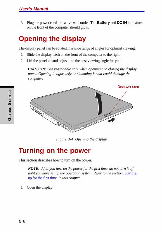
User's ManualG
ET
TIN
G S
TA
RT
ED
3-6
3. Plug the power cord into a live wall outlet. The Battery and DC IN indicatorson the front of the computer should glow.
Opening the displayThe display panel can be rotated in a wide range of angles for optimal viewing.
1. Slide the display latch on the front of the computer to the right.
2. Lift the panel up and adjust it to the best viewing angle for you.
CAUTION: Use reasonable care when opening and closing the displaypanel. Opening it vigorously or slamming it shut could damage thecomputer.
Figure 3-4 Opening the display
Turning on the powerThis section describes how to turn on the power.
NOTE: After you turn on the power for the first time, do not turn it offuntil you have set up the operating system. Refer to the section, Startingup for the first time, in this chapter.
1. Open the display.
DISPLAY LATCH
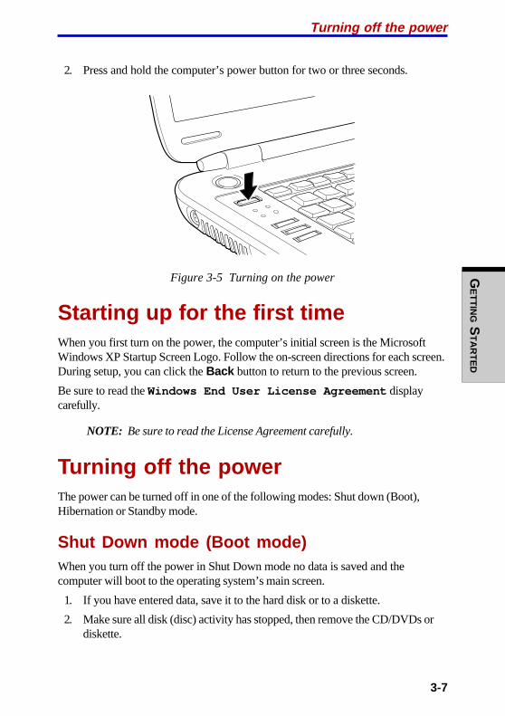
3-7
GE
TT
ING S
TA
RT
ED
2. Press and hold the computer’s power button for two or three seconds.
Figure 3-5 Turning on the power
Starting up for the first timeWhen you first turn on the power, the computer’s initial screen is the MicrosoftWindows XP Startup Screen Logo. Follow the on-screen directions for each screen.During setup, you can click the Back button to return to the previous screen.
Be sure to read the Windows End User License Agreement displaycarefully.
NOTE: Be sure to read the License Agreement carefully.
Turning off the powerThe power can be turned off in one of the following modes: Shut down (Boot),Hibernation or Standby mode.
Shut Down mode (Boot mode)When you turn off the power in Shut Down mode no data is saved and thecomputer will boot to the operating system’s main screen.
1. If you have entered data, save it to the hard disk or to a diskette.
2. Make sure all disk (disc) activity has stopped, then remove the CD/DVDs ordiskette.
Turning off the power
User's ManualG
ET
TIN
G S
TA
RT
ED
3-8
CAUTION: Make sure the Disk indicator is off. If you turn off the powerwhile a disk (disc) is being accessed, you can lose data or damage thedisk (disc).
3. Click start then click Turn Off Computer . From the Turn Off Com-puter menu select Turn Off .
4. Turn off the power to any peripheral devices.
CAUTION: Do not turn the computer or devices back on immediately. Waita moment to let all capacitors fully discharge.
Hibernation modeThe hibernation feature saves the contents of memory to the hard disk when thecomputer is turned off. The next time the computer is turned on, the previous stateis restored. The hibernation feature does not save the status of peripheral devices.
CAUTIONS: 1. Save your data. While entering hibernation mode, thecomputer saves the contents of memory to the HDD.However, for safety sake, it is best to save your datamanually.
2. Data will be lost if you remove the battery or discon-nect the universal AC adaptor before the save iscompleted. Wait for the Disk indicator to go out.
3. Do not install or remove a memory module while thecomputer is in hibernation mode. Data will be lost.
Benefits of hibernation
The hibernation feature provides the following benefits:
❖❖❖❖❖ Saves data to the hard disk when the computer automatically shuts downbecause of a low battery.
NOTE: For the computer to shut down in hibernation mode, the hiberna-tion feature must be enabled in two places in TOSHIBA Power Saver: theHibernate window and the Battery Alarm item of the Alarm window.Otherwise, the computer will shut down in Standby mode. If battery powerbecomes depleted, data saved in Standby will be lost.
❖❖❖❖❖ You can return to your previous working environment immediately when youturn on the computer.

3-9
GE
TT
ING S
TA
RT
ED
❖❖❖❖❖ Saves power by shutting down the system when the computer receives noinput or hardware access for the duration set by the System hibernate feature.
❖❖❖❖❖ You can use the panel power off feature.
Starting Hibernation
NOTE: You can also enable Hibernation by pressing Fn + F4. SeeChapter 5, The Keyboard, for details.
To enter Hibernation mode, follow the steps below.
1. Click start .
2. Select Turn Off Computer .
3. Open the Turn Off Computer dialog box. Hibernate is not displayed.
4. Press the Shift key. The Standby item will change to Hibernate .
5. Select Hibernate .
Automatic Hibernation
The computer will enter Hibernate mode automatically when you press the powerbutton or close the lid. First, however, make the appropriate settings according tothe steps below.
1. Open the Control Panel .
2. Open Performance and Maintenance and open Power Options .
3. Select the Hibernate window in the Power Options Properties ,select the Enable hibernation check box and click the Apply button.
4. Open TOSHIBA Power Saver .
5. Select the Setup Action window.
6. Enable the desired Hibernation settings for When I press the powerbutton and When I close the lid .
7. Click the OK button.
Turning off the power

User's ManualG
ET
TIN
G S
TA
RT
ED
3-10
Data save in hibernation mode
When you turn off the power in hibernation mode, the computer takes a moment tosave current memory data to the hard disk. During this time, the Disk indicator willlight.
After you turn off the computer and memory is saved to the hard disk, turn off thepower to any peripheral devices.
CAUTION: Do not turn the computer or devices back on immediately.Wait a moment to let all capacitors fully discharge.
Standby modeIf you have to interrupt your work, you can turn off the power without exiting fromyour software. Data is maintained in the computer’s main memory. When you turnon the power again, you can continue working right where you left off.
NOTES: 1. When the AC adaptor is connected, the computer will gointo Standby mode according to the settings in theTOSHIBA Power Saver utility.
2. To restore operation from Standby mode, press the powerbutton or press any key. The latter action works only ifWake-up on Keyboard is enabled in HW Setup.
3. If the computer automatically enters Standby mode while anetwork application is active, the application might not berestored when the computer wakes up from Standby.
4. To prevent the computer from automatically enteringStandby mode, disable Standby in TOSHIBA Power Saver.That action, however, will nullify the computer’s EnergyStar compliance.
CAUTIONS: 1. Before entering Standby mode, be sure to save your data.
2. Do not install or remove a memory module while thecomputer is in standby mode. The computer or themodule could be damaged.
3. Do not remove the battery pack while the computer is instandby mode (unless the computer is connected to anAC power source). Data in memory will be lost.

3-11
GE
TT
ING S
TA
RT
ED
4. If you carry the computer on board an aircraft or into ahospital, be sure to shut down the computer in hiberna-tion mode or in shutdown mode to avoid radio signalinterference.
Benefits of standby
The standby feature provides the following benefits:
❖❖❖❖❖ Restores the previous working environment more rapidly than does hiberna-tion.
❖❖❖❖❖ Saves power by shutting down the system when the computer receives noinput or hardware access for the duration set by the System Standby feature.
❖❖❖❖❖ You can use the panel power off feature.
Executing standby
NOTE: You can also enable Standby by pressing Fn + F3. See Chapter5, The Keyboard, for details.
You can enter standby mode in one of three ways:
1. Click start , click Turn Off Computer and click Stand by .
2. Close the display panel. This feature must be enabled. Refer to the SystemPower Mode item in Power Saver Utility in the Control Panel.
Open Performance and Maintenance and open TOSHIBA PowerSaver .
3. Press the power button. This feature must be enabled. Refer to the SystemPower Mode item in Power Saver Utility in the Control Panel.
Open Performance and Maintenance and open TOSHIBA PowerSaver .
When you turn the power back on, you can continue where you left when you shutdown the computer.
NOTES: 1. When the computer is shut down in standby mode, thePower indicator flashes orange.
2. If you are operating the computer on battery power, youcan lengthen the operating time by shutting down inhibernation mode. Standby mode consumes more power.
Turning off the power

User's ManualG
ET
TIN
G S
TA
RT
ED
3-12
Standby limitations
Standby will not function under the following conditions:
❖❖❖❖❖ Power is turned back on immediately after shutting down.
❖❖❖❖❖ Memory circuits are exposed to static electricity or electrical noise.
Restarting the computerCertain conditions require that you restart the system. For example, if:
❖❖❖❖❖ You change certain computer settings.
❖❖❖❖❖ An error occurs and the computer does not respond to your keyboardcommands.
There are three ways to restart the computer system:
1. Click start then click Turn Off Computer . From the Turn Off Com-puter menu select Restart .
2. Press Ctrl + Alt + Del to display the Windows Task Manager , thenselect Shutdown and Restart .
3. Press the power button and hold it down for five seconds. Wait 10 to 15seconds, then turn the power on again by pressing the power button.
Restoring the preinstalled softwareIf preinstalled files are damaged, use the Product Recovery CD-ROM to restorethem. To restore the operating system and all preinstalled software, follow the stepsbelow.
CAUTION: When you reinstall the Windows operating system, the harddisk will be reformatted and all data will be lost.
1. Load the Product Recovery CD-ROM in the optical media drive and turn offthe computer’s power.
2. Hold down the F12 key and turn on the power. When In Touch withTomorrow TOSHIBA appears, release the F12 key.
3. Use the up or down cursor key to select the CD/DVD-ROM Drive in theBoot Devices menu. For details, refer to the Boot priority section inChapter 7, HW Setup.
4. Follow the on-screen instructions.
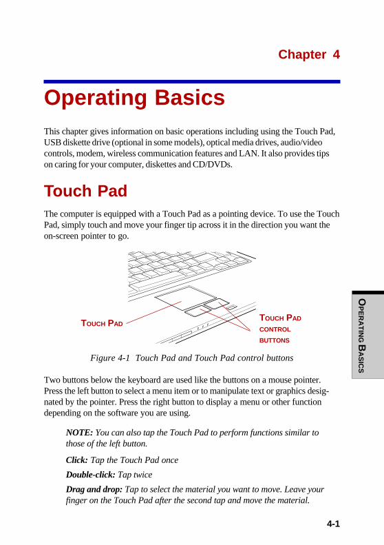
OP
ER
AT
ING B
AS
ICS
4-1
Chapter 4
Operating BasicsThis chapter gives information on basic operations including using the Touch Pad,USB diskette drive (optional in some models), optical media drives, audio/videocontrols, modem, wireless communication features and LAN. It also provides tipson caring for your computer, diskettes and CD/DVDs.
Touch PadThe computer is equipped with a Touch Pad as a pointing device. To use the TouchPad, simply touch and move your finger tip across it in the direction you want theon-screen pointer to go.
Figure 4-1 Touch Pad and Touch Pad control buttons
Two buttons below the keyboard are used like the buttons on a mouse pointer.Press the left button to select a menu item or to manipulate text or graphics desig-nated by the pointer. Press the right button to display a menu or other functiondepending on the software you are using.
NOTE: You can also tap the Touch Pad to perform functions similar tothose of the left button.
Click: Tap the Touch Pad once
Double-click: Tap twice
Drag and drop: Tap to select the material you want to move. Leave yourfinger on the Touch Pad after the second tap and move the material.
TOUCH PAD
CONTROL
BUTTONS
TOUCH PAD

User's ManualO
PE
RA
TIN
G B
AS
ICS
4-2
Using the USB diskette driveA 3 1/2" diskette drive connects to the computer’s USB port. It accommodates 1.44-megabyte or 720-kilobyte diskettes. Refer to Chapter 2, The Grand Tour, for moreinformation.
Connecting 3 1/2" diskette driveTo connect the drive, plug the diskette drive connector into a USB port. Refer toFigure 4-2.
CAUTION: Make sure the connector is right side up and properlyaligned with the socket. Do not try to force the connection, doing so candamage the connecting pins.
Figure 4-2 Connecting the USB diskette drive
NOTE: If you connect the diskette drive to use under Windows afterturning on the computer, it will take about 10 seconds for the computerto recognize the drive. Do not disconnect and reconnect before 10seconds has elapsed.

OP
ER
AT
ING B
AS
ICS
4-3
Disconnecting 3 1/2" diskette driveWhen you have finished using the diskette drive, follow the procedures below todisconnect it:
1. Wait for the indicator light to go out to make sure all diskette activity hasstopped.
CAUTION: If you disconnect the diskette drive or turn off the powerwhile the computer is accessing the drive you may lose data or damagethe diskette or the drive.
2. Click the Safety Remove Hardware icon on the Task Bar.
3. Click Diskette drive .
4. Pull the diskette drive connector out of the USB port.
Using optical media drivesThe illustrations in this section might differ slightly from your drive, but operation isthe same for all optical media drives. The full-size drive provides high-performanceexecution of CD/DVD-ROM-based programs. You can run either 12 cm (4.72") or 8cm (3.15") CD/DVDs without an adaptor. An ATAPI interface controller is used forCD/DVD-ROM operation. When the computer is accessing a CD/DVD, an indicatoron the drive glows.
NOTE: Use the WinDVD 4 application to view DVD-Video discs.
If you have a CD-RW/DVD-ROM drive, refer also to the Writing CDs on CD-RW/DVD-ROM drive section for precautions on writing to CDs.
If you have a DVD-R/-RW drive, refer also to the Writing CD/DVDs on DVD-R/-RWdrive section for precautions on writing to CDs.
If you have a DVD Multi drive, refer also to the Writing CD/DVDs on DVD Multidrive section for precautions on writing to CDs.
Using optical media drives

User's ManualO
PE
RA
TIN
G B
AS
ICS
4-4
Loading discsTo load CD/DVDs, follow the steps below and refer to figures 4-3 to 4-7.
1. a. When the power is on, press the eject button to open the drawer slightly.
Figure 4-3 Pressing the eject button
b. Pressing the eject button will not open the drawer when the drive’s poweris off. If the power is off, you can open the drawer by inserting a slenderobject (about 15 mm) such as a straightened paper clip into the eject holejust to the right of the eject button.
15mm
Diameter 1.0mm
Figure 4-4 Manual release with the eject hole
EJECT BUTTON
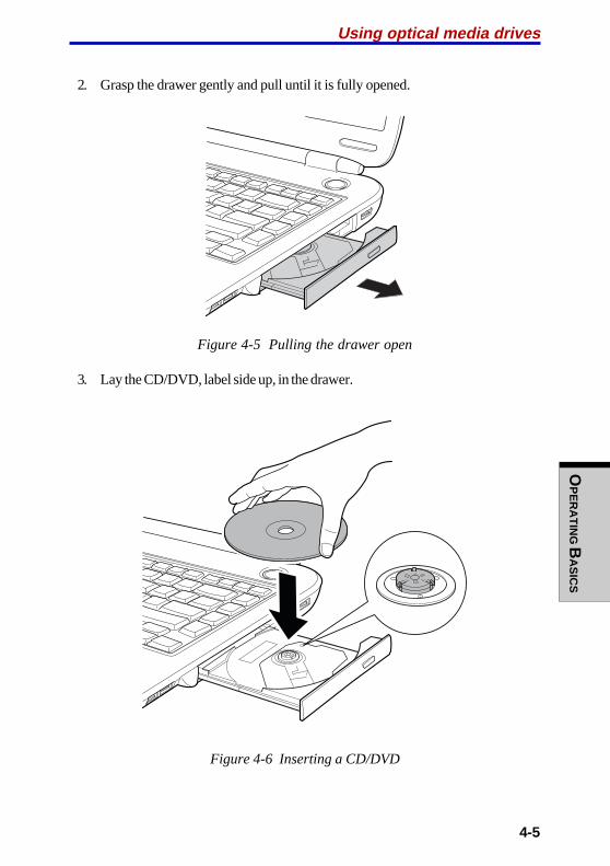
OP
ER
AT
ING B
AS
ICS
4-5
2. Grasp the drawer gently and pull until it is fully opened.
Figure 4-5 Pulling the drawer open
3. Lay the CD/DVD, label side up, in the drawer.
Figure 4-6 Inserting a CD/DVD
Using optical media drives

User's ManualO
PE
RA
TIN
G B
AS
ICS
4-6
NOTE: When the drawer is fully opened, the edge of the computer willextend slightly over the CD/DVD tray. Therefore, you will need to turnthe CD/DVD at an angle when you place it in the tray. After seating theCD/DVD, however, make sure it lies flat, as shown in figure 4-6.
CAUTIONS: 1. Do not touch the laser lens. Doing so could causemisalignment.
2. Be careful to keep foreign matter from entering thedrive. Check the back edge of the tray to make sure itcarries no debris before closing the drive.
4. Press gently at the center of the CD/DVD until you feel it click into place. TheCD/DVD should lie below the top of the spindle, flush with the spindle base.
5. Push the center of the drawer to close it. Press gently until it locks into place.
CAUTION: If the CD/DVD is not seated properly when the drawer isclosed, the CD/DVD might be damaged. Also, the drawer might not openfully when you press the eject button.
Figure 4-7 Closing the CD/DVD drawer
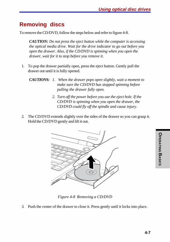
OP
ER
AT
ING B
AS
ICS
4-7
Using optical disc drives
Removing discsTo remove the CD/DVD, follow the steps below and refer to figure 4-8.
CAUTION: Do not press the eject button while the computer is accessingthe optical media drive. Wait for the drive indicator to go out before youopen the drawer. Also, if the CD/DVD is spinning when you open thedrawer, wait for it to stop before you remove it.
1. To pop the drawer partially open, press the eject button. Gently pull thedrawer out until it is fully opened.
CAUTIONS: 1. When the drawer pops open slightly, wait a moment tomake sure the CD/DVD has stopped spinning beforepulling the drawer fully open.
2. Turn off the power before you use the eject hole. If theCD/DVD is spinning when you open the drawer, theCD/DVD could fly off the spindle and cause injury.
2. The CD/DVD extends slightly over the sides of the drawer so you can grasp it.Hold the CD/DVD gently and lift it out.
Figure 4-8 Removing a CD/DVD
3. Push the center of the drawer to close it. Press gently until it locks into place.

User's ManualO
PE
RA
TIN
G B
AS
ICS
4-8
Audio/Video controlsThis section describes how to use the audio/video control buttons. You do nothave to turn on the computer’s operating system to play audio CD/DVDs. Thefollowing controls let you use the computer as a stand-alone CD/DVD player.When the operating system is running, the buttons control video as well as audio.
Mode Control buttonBesides the CD/DVD and Digital control functions described in the chart in the nextsection, you can use the Mode Control button to turn off the computer.
Controls for CD/DVD and Digital AudioThe chart below describes controls for CD/DVD and Digital Audio.
CD/DVD control Digital Audio control
Power is off If an audio CD is in the optical Operating system startsand you press media drive, the system enters and Digital Audio DataPlay/Pause CD Player mode and operates play begins.
as a stand-alone CD player.
If a DVD is in the opticalmedia drive, the operatingsystem starts and the DVDVideo player starts.
OS is running If an audio CD is in the optical Digital Audio Data playand you press media drive and CD audio play begins.Play/Pause begins.
If a DVD is in the optical mediadrive, the DVD Video playerstarts and DVD Video playbegins.
OP
ER
AT
ING B
AS
ICS
4-9
You press If power is on, it turns off. If If power is on, it turnsMode Control power is off it turns on in off.for three CD player mode.seconds
OS is running The mode changes to The mode changes toand you press Digital/Audio. CD/DVD.Mode Control
NOTES: 1. If the computer power is off, the CD/DVD control functionsonly for the optical media drive. If you want to control theoptical media drive by CD/DVD control when the OS isbooted up, set the appropriate player application soft-ware. You cannot play optical media, only by setting theinternal CD/DVD play drive on the Media Apps tab of theTOSHIBA Controls.
2. To play Digital Audio Data, you must set the play list in theWindows Media Player. The next time you play DigitalAudio Data, the former play list will become active. If a CDwas played the previous time, then All Audio will be used.
CAUTION: Do not install or remove a memory module while the opticalmedia drive power is on in CD Player mode. First press the Mode controlbutton to turn off the power to the optical media drive.
Next and Previous buttonsA single button on a rocker controls the Next and Previous functions. Press onthe icon to select the desired function.
Next Press the icon to advance to the next track, chapter or data.
Previous Press the icon to advance to the previous track, chapter or data.
NOTE: If Random is selected in Windows Media Player, selecting Nextor Previous advances to a random selection.
Audio/Video controls
User's ManualO
PE
RA
TIN
G B
AS
ICS
4-10
Play/Pause and Stop buttonsA single button on a rocker controls the Play/Pause and Stop functions. Presson the icon to select the desired function.
Play/Pause Press the icon to begin or pause play.
Stop Press the icon to stop play.
AudioThis section describes audio controls including sound levels and power manage-ment.
Volume control
The Volume Control utility lets you control the audio volume in Windows for bothplayback and recording.
❖❖❖❖❖ To launch Volume Control for playback, click Start , point to All Programs ,point to Accessories , point to Entertainment and click Volume Control .
❖❖❖❖❖ To launch Recording Control, click Options , point to Properties , chooseRecording and click OK.
❖❖❖❖❖ To view details of the Volume Control, click Help on the Volume Control.
Microphone level
The change the microphone gain, follow the steps below.
1. Click Start , point to All Programs , point to Accessories , point to Enter-tainment and click Volume Control .
2. Click Options and select Advanced Controls .
3. Click Advanced .
4. Check the Microphone Boost checkbox.
Audio controller
The audio controller can be powered down when the audio function is idle. Toenable Audio Power Management, follow the steps below.
1. Click Start , point to All Programs , point to Accessories , point to Enter-tainment and click Volume Control .
2. Double-click the SigmaTel Audio icon.

OP
ER
AT
ING B
AS
ICS
4-11
Power management
1. Clicked the Advanced tab.
2. Select the Enable Power Management check box.
3. Input a time in Time to Power Saving State .
NOTE: If the Enable Power Management check box is notselected, the audio controller always runs.
Figure 4-9 Advanced window
Sound quality
Adjust the equalizer settings to enhance sound quality.
Figure 4-10 Equalizer window
Audio/Video controls

User's ManualO
PE
RA
TIN
G B
AS
ICS
4-12
Feedback
Your computer’s built-in microphone can be used to record monaural sounds intoyour applications and to issue voice commands to applications that support suchfunctions.
Since your computer also has built-in speakers, “feedback” may be heard undercertain conditions. Feedback occurs when sound from the speaker is picked up inthe microphone and amplified back to the speaker, which amplifies it again to themicrophone.
This feedback occurs repeatedly and causes a loud, high-pitched noise. It is acommon phenomenon that occurs in any sound system when the microphone inputis output to the speaker (throughput) and the speaker volume is too loud or tooclose to the microphone. You can control throughput by adjusting the volume asdescribed in the Volume control item in this section.
Writing CDs on CD-RW/DVD-ROMdriveDepending on the type of drive installed, you may be able to write CDs. The CD-RW/DVD-ROM drive lets you write as well as read CD-ROMs. Observe theprecautions in this section to ensure the best performance for writing CDs. Forinformation on loading and unloading CDs refer to the Using optical media drivessection.
NOTE: CD-R discs can be written to only once. CD-RW discs can berewritten many times.
Before writing or rewritingPlease observe the following points when you write or rewrite the data.
❖❖❖❖❖ We recommend the following manufacturers of CD-R and CD-RW media.Media quality can affect write or rewrite success rates.
CD-R: TAIYOYUDEN CO., LTD.
MITUBISHI CHEMICAL CORPORATION
RICOH Co., Ltd.
Hitachi Maxell Ltd.
CD-RW: MITUBISHI CHEMICAL CORPORATION
RICOH Co., Ltd.
OP
ER
AT
ING B
AS
ICS
4-13
Writing CDs on CD-RW/DVD-ROM drive
TOSHIBA has confirmed the operation of CD-R and CD-RW media of the manufac-turers above. Operation of other media cannot be guaranteed.
❖❖❖❖❖ CD-RW can generally be rewritten about 1,000 times. However, the actualnumber of rewrites is affected by the quality of the media and the way it isused.
❖❖❖❖❖ Be sure to connect the universal AC adaptor when you write or rewrite.
❖❖❖❖❖ Be sure to close all other software programs except the writing software.
❖❖❖❖❖ Do not run software such as a screen saver which can put a heavy load on theCPU.
❖❖❖❖❖ Operate the computer at full power. Do not use power-saving features.
❖❖❖❖❖ Do not write while virus check software is running. Wait for it to finish, thendisable virus detection programs including any software that checks filesautomatically in the background.
❖❖❖❖❖ Do not use hard disk utilities, including those intended to enhance HDDaccess speed. They may cause unstable operation and damage data.
❖❖❖❖❖ Write from the computer's HDD to the CD. Do not try to write from shareddevices such as a LAN server or any other network device.
❖❖❖❖❖ Writing with software other than Drag’n Drop CD+DVD has not been con-firmed. Therefore, operation with other software cannot be guaranteed.
When writing or rewritingNote the following when you write or rewrite a CD-R or CD-RW.
❖❖❖❖❖ Always copy data from the HDD to the CD. Do not use cut-and-paste. Theoriginal data will be lost if there is a write error.
❖❖❖❖❖ Do not perform any of the following actions:
• Change users in the Windows XP operating system.
• Operate the computer for any other function, including use of a mouse orTouch Pad, closing/opening the LCD panel.
• Start a communication application such as a modem.
• Apply impact or vibration to the PC.
• Install, remove or connect external devices, including the following:
PC card, SD card, USB devices, external display, optical digital devices.
• Use the CD/MP3 control buttons to reproduce music and voice.
• Open the optical media drive.

User's ManualO
PE
RA
TIN
G B
AS
ICS
4-14
❖❖❖❖❖ If the media is poor in quality, dirty or damaged, writing or rewriting errors mayoccur.
❖❖❖❖❖ Set the computer on a level surface and avoid places subject to vibration suchas airplanes trains, or cars. Do not use an unstable surface such as a stand.
❖❖❖❖❖ Keep mobile phones and other wireless communication devices away from thecomputer.
Writing CD/DVDs on DVD-R/-RW driveYou can use the DVD-R/-RW drive to write data to either CD-R/RW or DVD-R/-RWdiscs. The following applications for writing are supplied on CD-ROM:Drag’n Drop CD+DVD, licensed by Easy Systems Japan Ltd., and DigiOn Inc.,InterVideo WinDVD Creator 2 Platinum, which is a product of InterVideo, Inc.
Important messageBefore you write or rewrite to CD-R/RW or DVD-R/-RW disc, read and follow all set-up and operating instructions in this section. If you fail to do so, the DVD-R/-RWdrive may not function properly, and you may fail to write or rewrite, lose data orincur other damage.
NOTE: Also refer to the disc-writing instructions in the next section,Writing CD/DVDs on DVD Multi drive.
DisclaimerTOSHIBA does not bear responsibility for the following:
❖❖❖❖❖ Damage to any CD-R/RW or DVD-R/-RW disc that may be caused by writingor rewriting with this product.
❖❖❖❖❖ Any change or loss of the recorded contents of CD-R/RW or DVD-R/-RW discthat may be caused by writing or rewriting with this product, or for anybusiness profit loss or business interruption that may be caused by the changeor loss of the recorded contents.
❖❖❖❖❖ Damage that may be caused by using third party equipment or software.
Given the technological limitations of current optical disc writing drives, you mayexperience unexpected writing or rewriting errors due to disc quality or problemswith hardware devices. Also, it is a good idea to make two or more copies ofimportant data, in case of undesired change or loss of the recorded contents.
OP
ER
AT
ING B
AS
ICS
4-15
Writing CD/DVDs on DVD Multi driveYou can use the DVD Multi drive to write data to either CD-R/RW or DVD-R/-RW/-RAM discs. The following applications for writing are supplied on CD-ROM:Drag’n Drop CD+DVD, licensed by Easy Systems Japan Ltd., and DigiOn Inc.,InterVideo WinDVD Creator 2 Platinum, which is a product of InterVideo, Inc.
Important messageBefore you write or rewrite to CD-R/RW or DVD-R/-RW/-RAM disc, read andfollow all set-up and operating instructions in this section. If you fail to do so, theDVD Multi drive may not function properly, and you may fail to write or rewrite,lose data or incur other damage.
DisclaimerTOSHIBA does not bear responsibility for the following:
❖❖❖❖❖ Damage to any CD-R/RW or DVD-R/-RW/-RAM disc that may be caused bywriting or rewriting with this product.
❖❖❖❖❖ Any change or loss of the recorded contents of CD-R/RW or DVD-R/-RW/-RAM disc that may be caused by writing or rewriting with this product, or forany business profit loss or business interruption that may be caused by thechange or loss of the recorded contents.
❖❖❖❖❖ Damage that may be caused by using third party equipment or software.
Given the technological limitations of current optical disc writing drives, you mayexperience unexpected writing or rewriting errors due to disc quality or problemswith hardware devices. Also, it is a good idea to make two or more copies ofimportant data, in case of undesired change or loss of the recorded contents.
Writing CD/DVDs on DVD Multi drive
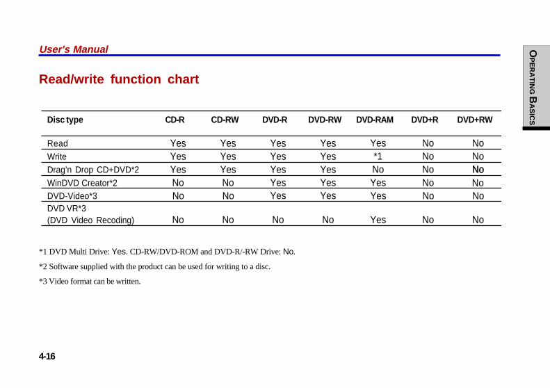
User's M
anualOPERATING BASICS
4-16
Read/write function chart
Disc type CD-R CD-RW DVD-R DVD-RW DVD-RAM DVD+R DVD+RW
ReadWriteDrag’n Drop CD+DVD*2
WinDVD Creator*2DVD-Video*3DVD VR*3
No NoNo No
No No NoNo No No
No
No No No No No No
No No Yes No No
(DVD Video Recoding)
Yes
Yes
Yes Yes
*1Yes Yes
Yes Yes
Yes YesYes Yes
Yes Yes YesYes YesYes Yes
No
*1 DVD Multi Drive: Yes. CD-RW/DVD-ROM and DVD-R/-RW Drive: No.
*2 Software supplied with the product can be used for writing to a disc.
*3 Video format can be written.
User's Manual OP
ER
AT
ING B
AS
ICS
4-16
OP
ER
AT
ING B
AS
ICS
4-17
❖❖❖❖❖ Based on TOSHIBA’s limited compatibility testing, we suggest the followingmanufacturers of CD-R/RW and DVD-R/-RW/-RAM disc. However, in noevent does TOSHIBA guarantee the operation, quality or performance of anydisc. Disc quality can affect write or rewrite success rates.
CD-R: TAIYOYUDEN CO., LTD.
MITUBISHI CHEMICAL CORPORATION
RICOH Co., Ltd.
Hitachi Maxell Ltd.
CD-RW: MITUBISHI CHEMICAL CORPORATION
RICOH Co., Ltd.
DVD-R: DVD Specifications for Recordable Disc for Gen-eral Version 2.0
TAIYOYUDEN CO., LTD.
PIONEER VIDEO CORPORATION
MITSUBISHI CHEMICAL CORPORATION
DVD-RW: DVD Specifications for Re-recordable Disc forVersion 1.1
VICTOR COMPANY OF JAPAN, LIMITED
TDK Corporation
DVD-RAM: DVD Specifications for DVD-RAM Disc for Version2.0 or Version 2.1
Matsushita Electric Industrial Co., Ltd.
❖❖❖❖❖ If the disc is poor in quality, dirty or damaged, writing or rewriting errors mayoccur. Be careful to check the disc for dirt or damage before you use it.
❖❖❖❖❖ The actual number of rewrites to CD-RW or DVD-RW/-RAM is affected by thequality of the disc and the way it is used.
❖❖❖❖❖ There are two types of DVD discs: authoring and general use discs. Do not useauthoring discs. Only general use discs can be written to by a computer drive.
❖❖❖❖❖ You can use DVD-RAM discs that can be removed from a cartridge and DVD-RAM discs designed without a cartridge. You cannot use a disc with a 2.6 GBsingle-sided capacity or 5.2 GB double-sided capacity.
❖❖❖❖❖ Other DVD-ROM drives for computers or other DVD players may not be ableto read DVD-R/-RW discs.
Writing CD/DVDs on DVD Multi drive

User's ManualO
PE
RA
TIN
G B
AS
ICS
4-18
❖❖❖❖❖ You cannot overwrite data that has been previously written to a DVD-RW disc.
❖❖❖❖❖ You cannot partially delete any data written to a DVD-RW disc.
❖❖❖❖❖ Data written to a CD-R/DVD-R disc cannot be deleted either in whole or in part.
❖❖❖❖❖ Data deleted (erased) from a CD-RW and DVD-RW/-RAM disc cannot berecovered. Check the content of the disc carefully before you delete it. Ifmultiple drives that can write data to discs are connected, be careful not todelete data from the wrong drive.
❖❖❖❖❖ In writing to a DVD-R/-RW disc, some disc space is required for file manage-ment, so you may not be able to write the full capacity of the disc.
❖❖❖❖❖ Since the disc is based on the DVD standard, it will be filled with dummy data ifthe written data is less than about 1 GB. Even if you write only a small amountof data, it might take time to fill in the dummy data.
❖❖❖❖❖ Two types of DVD-R/-RW/-RAM discs are on the market: data and video. Usea video disc to store video data. You can use video discs on a DVD recorder aswell as on your computer’s DVD-ROM drive. You cannot use data discs on aDVD recorder.
❖❖❖❖❖ DVD-RAM formatted by FAT32 cannot be read in Windows 2000 withoutDVD-RAM Driver Software.
Before writing or rewritingPlease observe the following points when you write or rewrite data.
❖❖❖❖❖ When multiple drives that can write data to discs are connected, be careful notto write to the wrong drive.
❖❖❖❖❖ Be sure to connect the universal AC adaptor before you write or rewrite.
❖❖❖❖❖ Before you enter standby/hibernation mode, be sure to finish DVD-RAMwriting. Writing is finished if you can eject DVD-RAM media.
❖❖❖❖❖ Be sure to close all other software programs except the writing software.
❖❖❖❖❖ Do not run software such as a screen saver, which can put a heavy load on theCPU.
❖❖❖❖❖ Operate the computer in the full-power mode. Do not use power-savingfeatures.
❖❖❖❖❖ Do not write while virus check software is running. Wait for it to finish, thendisable virus detection programs including any software that checks filesautomatically in the background.
❖❖❖❖❖ Do not use hard disk utilities, including those intended to enhance HDDaccess speed. They may cause unstable operation and data damage.
OP
ER
AT
ING B
AS
ICS
4-19
❖❖❖❖❖ Write from the computer's HDD to the CD/DVD. Do not try to write from shareddevices such as a LAN server or any other network device.
❖❖❖❖❖ Writing with software other than Drag’n Drop CD+DVD, InterVideo WinDVDCreator 2 Platinum is not recommended.
When writing or rewritingPlease observe/consider the following when you write or rewrite to a CD-R/RW orDVD-R/-RW/-RAM disc.
❖❖❖❖❖ Do not perform any of the following actions when writing or rewriting:
• Change users in the Windows XP operating system.
• Operate the computer for any other function, including using a mouse orTouch Pad or closing/opening the LCD panel.
• Start a communication application such as a modem.
• Apply impact or vibration to the computer.
• Install, remove or connect external devices, including the following:
PC card, SD card, USB devices, external display, optical digital devices.
• Use the Audio/Video control button to reproduce music or voice.
• Open the DVD Multi drive
❖❖❖❖❖ Do not use standby/hibernation while writing or rewriting.
❖❖❖❖❖ Make sure writing or rewriting is completed before going into standby/hibernation. Writing is completed if you can open the DVD Multi drive tray.
❖❖❖❖❖ Set the computer on a level surface and avoid places subject to vibration suchas airplanes, trains, or cars. Do not use an unstable surface such as a stand.
❖❖❖❖❖ Keep mobile phones and other wireless communication devices away from thecomputer.
❖❖❖❖❖ Always copy data from the HDD to the DVD-RAM. Do not use cut-and-paste.The original data will be lost if there is a write error.
Drag’n Drop CD+DVDNote the following limitations when you use Drag’n Drop CD+DVD:
❖❖❖❖❖ DVD-Video cannot be created using Drag’n Drop CD+DVD.
❖❖❖❖❖ DVD-Audio cannot be created using Drag’n Drop CD+DVD.
❖❖❖❖❖ You cannot use Drag’n Drop CD+DVD’s music CD function to record music toa DVD-R/-RW disc.
Writing CD/DVDs on DVD Multi drive

User's ManualO
PE
RA
TIN
G B
AS
ICS
4-20
❖❖❖❖❖ Do not use the DISC Backup function of Drag’n Drop CD+DVD to copy DVD-Video and DVD-ROM with copyright protection.
❖❖❖❖❖ DVD-RAM disc cannot be backed up with the DISC Backup function of Drag’nDrop CD+DVD.
❖❖❖❖❖ You cannot backup a CD-ROM or CD-R/RW to DVD-R/-RW using the DISCBackup function of Drag’n Drop CD+DVD.
❖❖❖❖❖ You cannot back up DVD-ROM, DVD-Video or DVD-R/-RW to CD-R/RWusing the DISC Backup function of Drag’n Drop CD+DVD.
❖❖❖❖❖ Drag’n Drop CD+DVD cannot record in packet format.
❖❖❖❖❖ You might not be able to use the DISC backup function of Drag’n DropCD+DVD to back up a DVD-R/-RW disc that was made with other software ona different DVD-R/-RW recorder.
❖❖❖❖❖ If you add data to a DVD-R disc that you have already recorded to, you mightnot be able to read the added data under some circumstances. It cannot be readin 16-bit operating systems, such as Windows 98SE and Windows ME. InWindows NT4, you will need Service Pack 6 or later to read added data. SomeDVD-ROM and CD-RW/DVD-ROM drives cannot read added data regardlessof the operating system.
❖❖❖❖❖ Drag’n Drop CD+DVD does not support recording to DVD-RAM discs. Torecord to a DVD-RAM, use Explorer or other utility.
❖❖❖❖❖ If you try to back up a DVD disc to a DVD-RW disc that was erased by theQuick erase option, you might get a error message. Use the Full erase option toclear the DVD-RW disc and try again.
❖❖❖❖❖ When you back up a DVD disc, be sure the source drive supports recording toDVD-R/-RW discs. If the source drive does not support recording to DVD-R/-RW discs, it might not be backed up correctly.
OP
ER
AT
ING B
AS
ICS
4-21
Data verificationTo verify that data is written or rewritten correctly, follow the steps below beforeyou write or rewrite a Data CD/DVD.
1. Right-click Data BOX and select Options to display the DATA DISCOption window.
2. Mark the Record and Verify check box and select Byte compare .
3. Click the OK button.
The “Record and Verify” function automatically checks whether data has beencorrectly recorded onto a CD/DVD. “Byte compare” compares the original data filewith the data recorded on the CD/DVD and checks that the data completelymatches.
Video (DVD-R/-RW/-RAM)Note the following limitations when you write video to DVD:
❖❖❖❖❖ When installing, uninstalling or InterVideo WinDVD Creator 2 Platinum, thecomputer should be set to system administrator or equivalent privilege.
❖❖❖❖❖ When Drag'n Drop or similar software is resident in the computer's memory, theDVD Multi drive locks. In this situation, other software cannot be used to writedata to the disc.
❖❖❖❖❖ While you are editing DVD-R/-RW/-RAM, you can display previews. How-ever, if an application other than WinDVD is running, the preview might notdisplay properly. To ensure proper display of previews, do not start otherapplications while you are editing DVD-R/-RW/-RAM disc.
❖❖❖❖❖ Do not change the resolution or the number of screen colors while InterVideoWinDVD Creator 2 Platinum is running.
❖❖❖❖❖ Although the online manual and Help files indicate that JPEG files can be used,in fact, they cannot be used.
❖❖❖❖❖ InterVideo WinDVD Creator 2 Platinum cannot make DVD-Audio, VideoCD,and miniDVD.
❖❖❖❖❖ DVD-R/-RW discs cannot be written in VR format.
❖❖❖❖❖ It may take several hours for InterVideo WinDVD Creator 2 Platinum to convertvideo to MPEG format, and several hours more to save the MPEG file to a DVDMulti drive.
❖❖❖❖❖ In order to write to a DVD-RW disc that has already been written to usingInterVideo WinDVD Creator 2 Platinum, you will first have to delete all of thedata with Drag’n Drop CD+DVD or similar software.
Writing CD/DVDs on DVD Multi drive

User's ManualO
PE
RA
TIN
G B
AS
ICS
4-22
❖❖❖❖❖ You will need 2 GB of empty hard disk space for every hour to write to a DVD-R/-RW disc.
❖❖❖❖❖ You cannot edit DVD-RAM video data that has copyright protection, usingInterVideo WinDVD Creator 2 Platinum.
Media careThis section provides tips on protecting data stored on your CD/DVDs anddiskettes.
Handle your media with care. The following simple precautions will increase thelifetime of your media and protect the data stored on them:
CD/DVDs1. Store your CD/DVDs in the container they came in to protect them and keep
them clean.
2. Do not bend the CD/DVD.
3. Do not write on, apply a sticker to, or otherwise mar the surface of theCD/DVD that contains data.
4. Hold the CD/DVD by its outside edge or the edge on the center hole. Finger-prints on the surface can prevent the drive from properly reading data.
5. Do not expose to direct sunlight, extreme heat or cold. Do not place heavyobjects on your CD/DVDs.
6. If your CD/DVDs become dusty or dirty, wipe them with a clean dry cloth.Wipe from the center out, do not wipe in a circular direction around the CD/DVD. If necessary, use a cloth dampened in water or a neutral cleaner. Do notuse benzine, thinner or similar cleaner.
Diskettes1. Store your diskettes in the container they came in to protect them and keep
them clean. If a diskette is dirty, do not use cleaning fluid. Clean it with a softdamp cloth.
2. Do not slide back the diskette’s protective metal covering or touch thediskette’s magnetic surface. Fingerprints may prevent the diskette drive fromreading data from the diskette.
3. Data may be lost if the diskette is twisted; bent; or exposed to direct sunlight,extreme heat or cold.

OP
ER
AT
ING B
AS
ICS
4-23
4. Do not place heavy objects on your diskettes.
5. Do not eat, smoke, or use erasers near your diskettes. Foreign particles insidethe diskette’s jacket can damage the magnetic surface.
6. Magnetic energy can destroy data on diskettes. Keep your diskettes awayfrom speakers, radios, television sets and other sources of magnetic fields.
ModemThis section describes how to connect and disconnect the internal modem to andfrom a telephone jack.
NOTE: The internal modem does not support voice functions. All dataand fax functions are supported.
CAUTIONS: 1. In case of a lightning storm, unplug the modem cablefrom the telephone jack.
2. Do not connect the modem to a digital telephone line.A digital line will damage the modem.
Region selectionTelecommunication regulations vary from one region to another, so you will need tomake sure the internal modem’s settings are correct for the region in which it will beused.
To select a region, follow the steps below.
1. Click start , point to All Programs , point to TOSHIBA , Networking andclick Modem Region Select .
NOTE: Do not use the Country/Region Select function in the Modemsetup utility in the Control Panel if the function is available. If youchange the Country/Region in the Control Panel, the change may nottake effect.
2. The Region Selection icon will appear in the Windows Task Bar.
3. Click the icon with the primary mouse button to display a list of regions thatthe modem supports. A sub menu for telephony location information will alsobe displayed. A check will appear next to the currently selected region andtelephony location.
Modem

User's ManualO
PE
RA
TIN
G B
AS
ICS
4-24
4. Select a region from the region menu or a telephony location from the sub-menu.
• When you click a region it becomes the modem’s region selection, and theNew Location for telephony will be set automatically.
• When you select a telephony location, the corresponding region is automati-cally selected and it becomes the modem’s current region setting.
Properties menuClick the icon with the secondary mouse button to display the following menu.
Setting
You can enable or disable the following settings:
AutoRun Mode
The Region Select utility starts automatically when you start up the operatingsystem.
Open the Dialing Properties dialog box after selecting region.
The dialing properties dialog box will be displayed automatically after youselect the region.
Location list for region selection.
A submenu appears displaying location information for telephony.
Open dialog box, if the modem and Telephony Current
Location region code do not match.
A warning dialog box is displayed if current settings for region code andtelephony location are incorrect.
Modem Selection
If the computer cannot recognize the internal modem, a dialog box is displayed.Select the COM port for your modem to use.
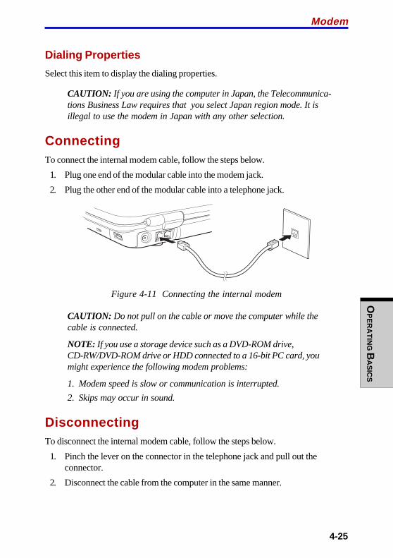
OP
ER
AT
ING B
AS
ICS
4-25
Dialing Properties
Select this item to display the dialing properties.
CAUTION: If you are using the computer in Japan, the Telecommunica-tions Business Law requires that you select Japan region mode. It isillegal to use the modem in Japan with any other selection.
ConnectingTo connect the internal modem cable, follow the steps below.
1. Plug one end of the modular cable into the modem jack.
2. Plug the other end of the modular cable into a telephone jack.
Figure 4-11 Connecting the internal modem
CAUTION: Do not pull on the cable or move the computer while thecable is connected.
NOTE: If you use a storage device such as a DVD-ROM drive,CD-RW/DVD-ROM drive or HDD connected to a 16-bit PC card, youmight experience the following modem problems:
1. Modem speed is slow or communication is interrupted.
2. Skips may occur in sound.
DisconnectingTo disconnect the internal modem cable, follow the steps below.
1. Pinch the lever on the connector in the telephone jack and pull out theconnector.
2. Disconnect the cable from the computer in the same manner.
Modem

User's ManualO
PE
RA
TIN
G B
AS
ICS
4-26
Wireless LANThe Wireless LAN is compatible with other LAN systems based on Direct Se-quence Spread Spectrum/Orthogonal Frequency Division Multiplexing radiotechnology that complies with IEEE802.11 Wireless LAN standard (Revision A, B orG) and Turbo Mode.
Supported featuresIt supports the following features:
❖❖❖❖❖ Automatic Transmit Rate Select mechanism in the transmit range of 54, 48, 36,24, 18, 12, 9 and 6 Mbit/s. (Revision A and G, Revision A/B, B/G, A/B/G combotype)
❖❖❖❖❖ Automatic Transmit Rate Select mechanism in the transmit range of 11, 5.5, 2and 1 Mbit/s. (Revision B)
❖❖❖❖❖ Automatic Transmit Rate Select mechanism in the transmit range of 108, 96.72,48, 36, 24, 18 and 12 Mbit/s. (Turbo Mode, Revision A/B/G combo type)
❖❖❖❖❖ Frequency Channel Selection (Revision A/Turbo Mode: 5 GHz, Revision B/G:2.4 GHz)
❖❖❖❖❖ Roaming over multiple channels
❖❖❖❖❖ Card Power Management
❖❖❖❖❖ Wired Equivalent Privacy (WEP) data encryption, based on the 152 bitencryption algorithm. (Revision B/G, A/B/G combo type) Wired EquivalentPrivacy (WEP) data encryption, based on the 128 bit encryption algorithm.(Revision B, A/B combo type)
❖❖❖❖❖ Advanced Encryption Standard (AES) data encryption, based on 256 bitencryption algorithm. (Revision B/G, A/B/G combo type)
NOTE: Wake-up on LAN does not function on a Wireless LAN.
OP
ER
AT
ING B
AS
ICS
4-27
Wireless LAN
Security❖❖❖❖❖ Be sure to enable the WEP (encryption) function to prevent unauthorized
access to your Wireless LAN. Such access can enable illegal intrusion intodata, eavesdropping and loss or destruction of data. TOSHIBA stronglyrecommends that you enable the WEP function.
❖❖❖❖❖ TOSHIBA is not liable for damage resulting from unauthorized access to aWireless LAN including, but not limited to, illegal intrusion, eavesdroppingand loss or destruction of data.
Wireless communication switchYou can enable or disable the Wireless LAN function, with the on/off switch. Notransmissions are sent or received when the switch is off. Slide the switch towardthe back of the computer to turn it on and toward the front of the computer to turn itoff.
CAUTIONS: 1. Set the switch to off in airplanes and hospitals. Checkthe indicator. It will stop glowing when the wirelesscommunication function is off.
2. Turn the computer off when you enter an airplane andcheck the carrier’s regulations before you use acomputer on board.
Wireless communication indicatorThe wireless communication indicator indicates the status of the wireless communi-cation functions.
Indicator status Indication
Indicator off Wireless communication switch is set to off.
Indicator glows Wireless communication switch is on.Wireless LAN is turned on by an application.
If you used the Task Bar to disable W-LAN, restart the computer or follow theprocedures below to enable the system to recognize W-LAN. Open or click thefollowing: start , Control Panel , System , Hardware Device Manager ,Network adapters , Intel ® PRO/Wireless LAN 2100 3B Mini PCI Adapteror Intel ® PRO/Wireless LAN 2100A 3B Mini PCI Adapter or AtherosAR5001X+ Wireless Network Adapter and enable .

User's ManualO
PE
RA
TIN
G B
AS
ICS
4-28
LANThe computer has built-in support for Ethernet LAN (10 megabits per second,10BASE-T) and Fast Ethernet LAN (100 megabits per second, 100BASE-Tx).This section describes how to connect/disconnect to a LAN.
CAUTIONS: 1. Do not install or remove an optional memory modulewhile Wake-up on LAN is enabled.
2. Do not connect any cable other than a LAN cable tothe LAN jack. It could cause damage or malfunction.
3. Do not connect the LAN cable to a power supply. Itcould cause damage or malfunction.
NOTES: 1. The Wake-up on LAN function consumes power even whenthe system is off. Leave the universal AC adaptor con-nected while using this feature.
2. When the Wake-up on LAN function is activated, the LANindicators do not glow while the computer is in standbymode (while it is waiting for a LAN wake-up signal).
Connecting LAN cable
CAUTION: The computer must be configured properly before connectingto a LAN. Logging onto a LAN using the computer’s default settingscould cause a malfunction in LAN operation. Check with your LANadministrator regarding set-up procedures.
If you are using Fast Ethernet LAN (100 megabits per second, 100BASE-TX), besure to connect with a CAT5 cable. You cannot use a CAT3 cable.
If you are using Ethernet LAN (10 megabits per second, 10BASE-T), you canconnect with either a CAT5 or a CAT3.
To connect the LAN cable, follow the steps below.
1. Turn off the power to the computer and to all external devices connected tothe computer.
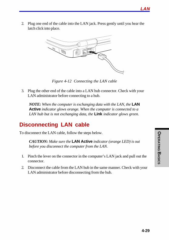
OP
ER
AT
ING B
AS
ICS
4-29
2. Plug one end of the cable into the LAN jack. Press gently until you hear thelatch click into place.
Figure 4-12 Connecting the LAN cable
3. Plug the other end of the cable into a LAN hub connector. Check with yourLAN administrator before connecting to a hub.
NOTE: When the computer is exchanging data with the LAN, the LANActive indicator glows orange. When the computer is connected to aLAN hub but is not exchanging data, the Link indicator glows green.
Disconnecting LAN cableTo disconnect the LAN cable, follow the steps below.
CAUTION: Make sure the LAN Active indicator (orange LED) is outbefore you disconnect the computer from the LAN.
1. Pinch the lever on the connector in the computer’s LAN jack and pull out theconnector.
2. Disconnect the cable from the LAN hub in the same manner. Check with yourLAN administrator before disconnecting from the hub.
LAN
User's ManualO
PE
RA
TIN
G B
AS
ICS
4-30
Cleaning the computerTo help ensure long, trouble-free operation, keep the computer free of dust and usecare with liquids around the computer.
❖❖❖❖❖ Be careful not to spill liquids into the computer. If the computer does get wet,turn the power off immediately and let the computer dry completely before youturn it on again.
❖❖❖❖❖ Clean the computer using dry cloth. You can use glass cleaner on the display.Spray a small amount of cleaner on a soft, clean cloth and wipe the screengently with the cloth.
CAUTION: Never spray cleaner directly onto the computer or let liquidrun into any part of it. Never use harsh or caustic chemical products toclean the computer.
Moving the computerThe computer is designed for rugged durability. However, a few simple precautionstaken when moving the computer will help ensure trouble-free operation.
❖❖❖❖❖ Make sure all disk activity has ended before moving the computer. Check theDisk indicators on the computer.
❖❖❖❖❖ If a CD/DVD is in the drive, remove it. Also make sure the drawer is securelyclosed.
❖❖❖❖❖ Turn off the power to the computer.
❖❖❖❖❖ Disconnect the universal AC adaptor and all peripherals before moving thecomputer.
❖❖❖❖❖ Close the display. Do not pick up the computer by its display panel.
❖❖❖❖❖ Use the carrying case when transporting the computer.
OP
ER
AT
ING B
AS
ICS
4-31
Heat dispersalTo protect from overheating, the CPU has an internal temperature sensor. If thecomputer’s internal temperature rises to a certain level, the cooling fan is turned onor the processing speed is lowered. You can select whether to control the CPUtemperature by turning on the fan first, then if necessary, lowering the CPU speed.Or, by lowering the CPU speed first, then if necessary, turning on the fan. Use theCooling Method item of the Power Save Mode window in TOSHIBA Power Saver.
Maximum Turn on the fan first, then if necessary, lower the CPUPerformance processing speed.
Performance Use a combination of the fan and lowering the CPUprocessing speed.
Battery optimized Lower the CPU processing speed first, then if necessaryturn on the fan.
When the CPU temperature falls to a normal range, the fan is turned off and the CPUoperation returns to standard speed.
NOTE: If the CPU temperature reaches an unacceptably high level witheither setting, the system automatically shuts down to prevent damage.Data in memory will be lost.
Heat dispersal
User's ManualO
PE
RA
TIN
G B
AS
ICS
4-32
5-1
TH
E KE
YB
OA
RD
Chapter 5
The KeyboardThe computer’s keyboard layouts are compatible with a 101/102-key enhancedkeyboard. By pressing some keys in combination, all the 101/102-key keyboardfunctions can be executed on the computer.
The number of keys on your keyboard depends on which country/region’skeyboard layout your computer is configured with. Keyboards for numerouslanguages are available.
There are five types of keys: typewriter keys, keypad overlay, function keys, softkeys and cursor control keys.
Typewriter keysThe typewriter keys, produce the upper- and lower-case letters, numbers, punctua-tion marks, and special symbols that appear on the screen.
There are some differences, however, between using a typewriter and using acomputer keyboard:
❖❖❖❖❖ Letters and numbers produced in computer text vary in width. Spaces, whichare created by a “space character,” may also vary depending on line justifica-tion and other factors.
❖❖❖❖❖ The lowercase l (el) and the number 1 (one) are not interchangeable oncomputers as they are on a typewriter.
❖❖❖❖❖ The uppercase O (oh) and the 0 (zero) are not interchangeable.
❖❖❖❖❖ The Caps Lock function key locks only the alphabetic characters in upper-case while the shift lock on a typewriter places all keys in the shifted position.
❖❖❖❖❖ The Shift keys, the Tab key, and the BkSp (backspace) key perform the samefunction as their typewriter counterparts but also have special computerfunctions.
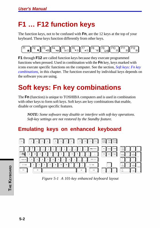
User's Manual
5-2
TH
E K
EY
BO
AR
D
F1 … F12 function keysThe function keys, not to be confused with Fn, are the 12 keys at the top of yourkeyboard. These keys function differently from other keys.
F1 through F12 are called function keys because they execute programmedfunctions when pressed. Used in combination with the Fn key, keys marked withicons execute specific functions on the computer. See the section, Soft keys: Fn keycombinations, in this chapter. The function executed by individual keys depends onthe software you are using.
Soft keys: Fn key combinationsThe Fn (function) is unique to TOSHIBA computers and is used in combinationwith other keys to form soft keys. Soft keys are key combinations that enable,disable or configure specific features.
NOTE: Some software may disable or interfere with soft-key operations.Soft-key settings are not restored by the Standby feature.
Emulating keys on enhanced keyboard
Esc
#
3Home PgUpBk Sp
F1 F2 F3 F4 F5 F6 F7 F8 F9 F10 F11 F12
!
1 2$
4
%
5 6 8 (
9
)
0
&
7
_ +=
PgDnEnd
Shift
Del
Ins
CapsLock
Shift
Enter
Q W R T Y U I O P{[
}]
E
~
`
A S D F G H J K L:;
@
?/
> .
< ,MNVCXZ B
\
^ *
+
-
Tab
AltAlt
Enter
7
Home
8 9
PgUp
654
1
End
2 3
PgDn
0
Ins
Num
Lock
.
Del
PrtSc Scroll
lock
Pause
Break
CtrlCtrl
SysReq
/ *.
,,,
Figure 5-1 A 101-key enhanced keyboard layout

5-3
TH
E KE
YB
OA
RD
Soft keys: Fn key combinations
The keyboard is designed to provide all the features of the 101-key enhancedkeyboard, shown in figure 5-1. The 101/102-key enhanced keyboard has a numerickeypad and scroll lock key. It also has additional Enter and Ctrl keys to the right ofthe main keyboard. Since the keyboard is smaller and has fewer keys, some of theenhanced keyboard functions must be simulated using two keys instead of one onthe larger keyboard.
Your software may require you to use keys that the keyboard does not have.Pressing the Fn key and one of the following keys simulates the enhancedkeyboard’s functions.
Press Fn + F10 or Fn + F11 to access the integrated keypad. When activated, thekeys with gray markings on the bottom edge become numeric keypad keys (Fn +F11) or cursor control keys (Fn + F10). Refer to the Keypad overlay section in thischapter for more information on how to operate these keys. The power on defaultfor both settings is off.
Press Fn + F12 (ScrLock ) to lock the cursor on a specific line. The power ondefault is off.
Press Fn + Enter to simulate Enter on the enhanced keyboard’s numeric keypad.
Press Fn + Ctrl to simulate the enhanced keyboard’s right Ctrl key.
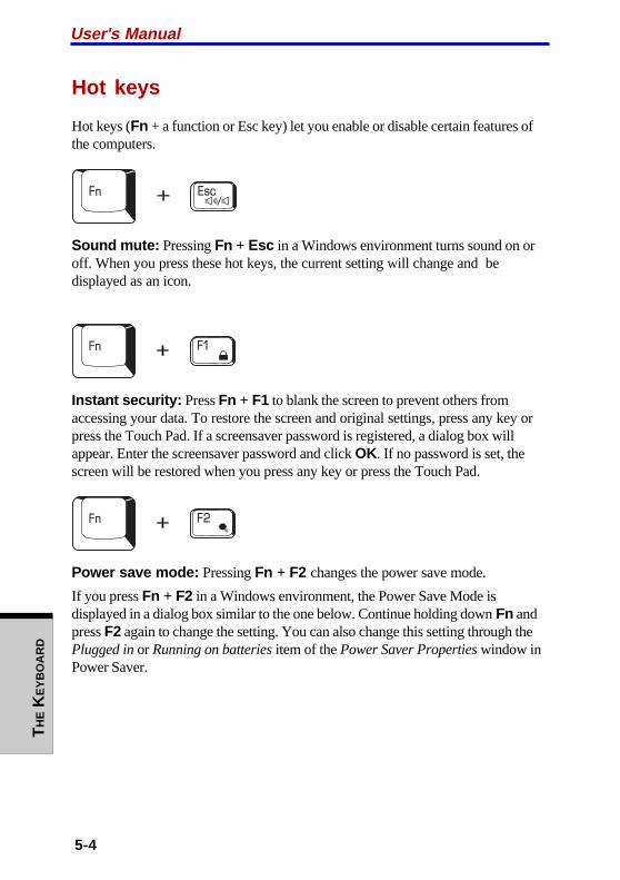
User's Manual
5-4
TH
E K
EY
BO
AR
D
Hot keys
Hot keys (Fn + a function or Esc key) let you enable or disable certain features ofthe computers.
Sound mute: Pressing Fn + Esc in a Windows environment turns sound on oroff. When you press these hot keys, the current setting will change and bedisplayed as an icon.
Instant security: Press Fn + F1 to blank the screen to prevent others fromaccessing your data. To restore the screen and original settings, press any key orpress the Touch Pad. If a screensaver password is registered, a dialog box willappear. Enter the screensaver password and click OK. If no password is set, thescreen will be restored when you press any key or press the Touch Pad.
Power save mode: Pressing Fn + F2 changes the power save mode.
If you press Fn + F2 in a Windows environment, the Power Save Mode isdisplayed in a dialog box similar to the one below. Continue holding down Fn andpress F2 again to change the setting. You can also change this setting through thePlugged in or Running on batteries item of the Power Saver Properties window inPower Saver.
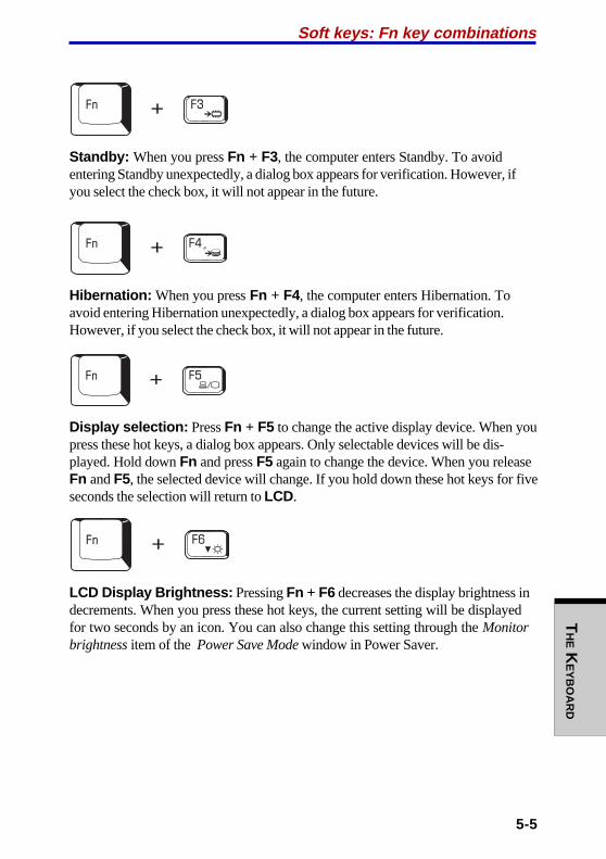
5-5
TH
E KE
YB
OA
RD
Standby: When you press Fn + F3, the computer enters Standby. To avoidentering Standby unexpectedly, a dialog box appears for verification. However, ifyou select the check box, it will not appear in the future.
Hibernation: When you press Fn + F4, the computer enters Hibernation. Toavoid entering Hibernation unexpectedly, a dialog box appears for verification.However, if you select the check box, it will not appear in the future.
Display selection: Press Fn + F5 to change the active display device. When youpress these hot keys, a dialog box appears. Only selectable devices will be dis-played. Hold down Fn and press F5 again to change the device. When you releaseFn and F5, the selected device will change. If you hold down these hot keys for fiveseconds the selection will return to LCD.
LCD Display Brightness: Pressing Fn + F6 decreases the display brightness indecrements. When you press these hot keys, the current setting will be displayedfor two seconds by an icon. You can also change this setting through the Monitorbrightness item of the Power Save Mode window in Power Saver.
Soft keys: Fn key combinations

User's Manual
5-6
TH
E K
EY
BO
AR
D
LCD Display Brightness: Pressing Fn + F7 increases the display brightness inincrements. When you press these hot keys, the current setting will be displayedfor two seconds by a pop-up icon. You can also change this setting through theMonitor brightness item of the Power Save Mode window in Power Saver.
NOTES: 1. The brightness level is always set at the maximum value forabout 18 seconds, when the LCD turns on. After 18seconds, the brightness level will appear at the PowerSave Mode setting or you can change it manually.
2. Display clarity increases with the brightness level.
Wireless setting: Fn + F8 are not used.
Touch Pad: Pressing Fn + F9 in a windows environment enables or disables theTouch Pad function. When you press these hot keys, the current setting willchange and be displayed as an icon.
Fn Sticky keyYou can use the TOSHIBA Accessibility Utility to make the Fn key sticky, that is,you can press it once, release it, and they press an “F number ” key. To start theTOSHIBA Accessibility Utility, click start , point to All Programs , point toTOSHIBA , point to Utilities and click Accessibility .

5-7
TH
E KE
YB
OA
RD
Windows special keysThe keyboard provides two keys that have special functions in Windows : oneactivates the start menu and the other has the same function as the secondarymouse button.
This key activates the Windows start menu.
This key has the same function as the secondary mouse button.
Keypad overlayYour computer’s keyboard does not have an independent numeric keypad, but itsnumeric keypad overlay functions like one.
The keys in the center of the keyboard with gray letters make up the numerickeypad overlay. The overlay provides the same functions as the numeric keypadon the 101/102-key enhanced keyboard in figure 5-2.
Turning on the overlaysThe numeric keypad overlay can be used for numeric data input or cursor and pagecontrol.
Arrow mode
To turn on the Arrow mode, press Fn + F10. The Arrow mode F10 indicatorlights. Now try cursor and page control using the keys shown in figure 5-2. PressFn + F10 again to turn off the overlay.
Keypad overlay

User's Manual
5-8
TH
E K
EY
BO
AR
D
Numeric mode
To turn on the Numeric mode, press Fn + F11. The Numeric mode F11 indicatorlights. Now try numeric data entry using the keys in figure 5-2. Press Fn + F11again to turn off the overlay.
Figure 5-2 The numeric keypad overlay
Temporarily using normal keyboard (overlay on)While using the overlay, you can temporarily access the normal keyboard withoutturning off the overlay:
1. Hold Fn and press any other key. All keys will operate as if the overlay wereoff.
2. Type upper-case characters by holding Fn + Shift and pressing a characterkey.
3. Release Fn to continue using the overlay.
5-9
TH
E KE
YB
OA
RD
Temporarily using overlay (overlay off)While using the normal keyboard, you can temporarily use the keypad overlaywithout turning it on:
1. Press and hold down Fn.
2. Check the keyboard indicators. Pressing Fn turns on the most recently usedoverlay. If the Numeric mode indicator lights, you can use the overlay fornumeric entry. If the Arrow mode indicator lights, you can use the overlay forcursor and page control.
3. Release Fn to return to normal keyboard operation.
Temporarily changing modesIf the computer is in Numeric mode , you can switch temporarily to Arrowmode by pressing a shift key.
If the computer is in Arrow mode , you can switch temporarily to Numericmode by pressing a shift key.
Generating ASCII charactersNot all ASCII characters can be generated using normal keyboard operation. But,you can generate these characters using their ASCII codes.
With the overlay on:
1. Hold down Alt .
2. Using the overlay keys, type the ASCII code.
3. Release Alt , and the ASCII character appears on the display screen.
With the overlay off:
1. Hold down Alt + Fn.
2. Using the overlay keys, type the ASCII code.
3. Release Alt + Fn, and the ASCII character appears on the display screen.
Generating ASCII characters

User's Manual
5-10
TH
E K
EY
BO
AR
D
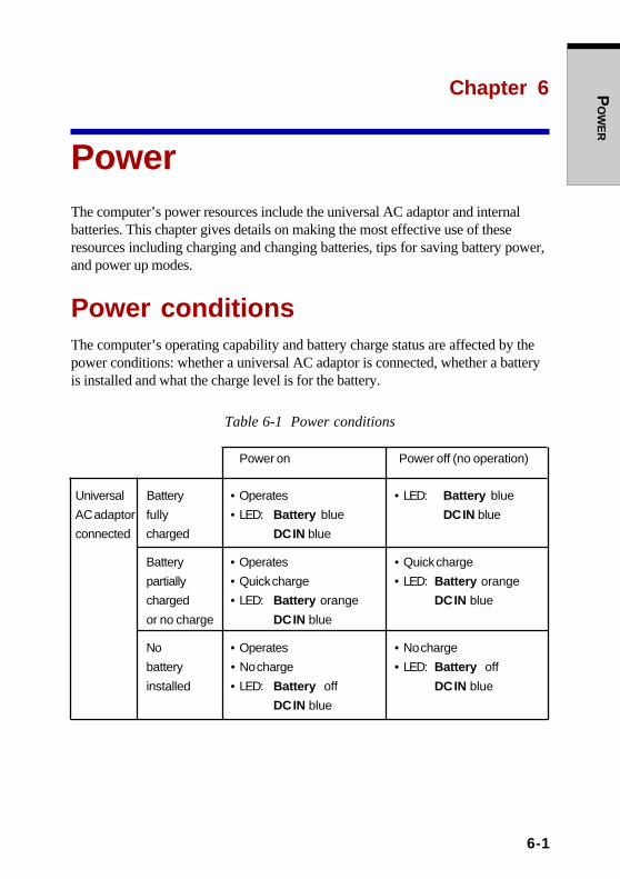
PO
WE
R
6-1
Chapter 6
PowerThe computer’s power resources include the universal AC adaptor and internalbatteries. This chapter gives details on making the most effective use of theseresources including charging and changing batteries, tips for saving battery power,and power up modes.
Power conditionsThe computer’s operating capability and battery charge status are affected by thepower conditions: whether a universal AC adaptor is connected, whether a batteryis installed and what the charge level is for the battery.
Table 6-1 Power conditions
Power on Power off (no operation)
Universal Battery • Operates • LED: Battery blue
AC adaptor fully • LED: Battery blue DC IN blue
connected charged DC IN blue
Battery • Operates • Quick charge
partially • Quick charge • LED: Battery orange
charged • LED: Battery orange DC IN blue
or no charge DC IN blue
No • Operates • No charge
battery • No charge • LED: Battery off
installed • LED: Battery off DC IN blue
DC IN blue

6-2
User's ManualP
OW
ER
Table 6-1 Power conditions continued
Power on Power off (no operation)
AC Battery • Operates
adaptor charge is • LED: Battery off
not above low DC IN off
connected battery
trigger point
Battery • Operates
charge is • LED: Battery
below low flashes orange
battery DC IN off
trigger point
Battery Computer goes
charge is into resume mode
exhausted shuts down
No • Cannot operate
battery • LED: Battery off
installed DC IN off
Power indicatorsAs shown in the above table, the Battery, DC IN and Power indicators on thesystem indicator alert you to the computer’s operating capability and battery chargestatus.
Battery indicatorCheck the Battery indicator to determine the status of the battery pack. Thefollowing indicator lights indicate the battery status:
Flashing orange The battery charge is low. The universal AC adaptor mustbe connected to recharge the battery.
Orange Indicates the universal AC adaptor is connected andcharging the battery.
Blue Indicates the universal AC adaptor is connected and thebattery is fully charged.

PO
WE
R
6-3
No light Under any other conditions, the indicator does not light.
NOTE: If the battery becomes too hot while it is being charged, thecharge will stop and the battery indicator will go out. When the battery’stemperature falls to a normal range, charge will resume. This occurswhether the computer’s power is on or off.
DC IN indicatorCheck the DC IN indicator to determine the power status with the universal ACadaptor connected:
Blue Indicates the universal AC adaptor is connected andsupplying proper power to the computer.
Flashing orange Indicates a problem with the power supply. Plug theuniversal AC adaptor into another outlet. If it still does notoperate properly, see your dealer.
No light Under any other conditions, the indicator does not light.
Power indicatorCheck the Power indicator to determine the power status:
Blue Indicates power is being supplied to the computer and thecomputer is turned on.
Blinking orange Indicates power is being supplied to the computer whilethe computer is in Standby mode. The indicator turns onfor one second and off for two seconds.
No light Under any other conditions, the indicator does not light.
Battery typesThe computer has two types of batteries:
❖❖❖❖❖ Battery pack
❖❖❖❖❖ Real Time Clock (RTC) battery
Battery packWhen the universal AC adaptor is not connected, the computer’s main powersource is a removable lithium ion battery pack, also referred to in this manual as thebattery pack. You can purchase additional battery packs for extended use of thecomputer away from an AC power source.
Battery types

6-4
User's ManualP
OW
ER
Before you remove the battery pack, set the computer to Hibernation mode or saveyour data and shut down the computer. Do not change the battery pack while theuniversal AC adaptor is connected.
CAUTIONS: 1. The battery pack is a lithium ion battery, which canexplode if not properly replaced, used, handled ordisposed of. Dispose of the battery as required by localordinances or regulations. Use only batteries recom-mended by TOSHIBA as replacements.
2. Do not remove the battery pack while the computer isin Standby mode. Data is stored in RAM, so if thecomputer loses power it will be lost. When the com-puter is powered off in Standby mode, and the univer-sal AC adaptor is not connected, the battery packsupplies power to maintain data and program inmemory. If the battery pack is completely discharged,Standby mode does not function and the computerloses all data in memory.
To ensure that the battery pack maintains its maximum capacity, operate thecomputer on battery power at least once a month until the battery pack is fullydischarged. Refer to Extending battery life in this chapter for procedures. If thecomputer is continuously operated on AC power through a universal AC adaptorfor an extended period, more than a month, the battery may fail to retain a charge. Itmay not function efficiently over the expected life of the battery and the Batteryindicator may not indicate a low-battery condition.
Real Time Clock batteryThe Real Time Clock (RTC) battery provides power for the internal real time clockand calendar. It also maintains the system configuration.
If the RTC battery becomes completely discharged, the system loses this data andthe real time clock and calendar stop working. The following message appears whenyou turn on the power:
0250: RTC battery is low0251: CMOS checksum is inconsistent
CAUTION: The computer’s RTC battery is a nickel metal hydride(NiMH) battery and should be replaced only by your dealer or by aTOSHIBA service representative. The battery can explode if not properlyreplaced, used, handled or disposed of. Dispose of the battery asrequired by local ordinances or regulations.

PO
WE
R
6-5
Care and use of the battery packThe battery pack is a vital component of portable computing. Taking proper care ofit will help ensure longer operating time on battery power as well as a longer life foryour battery pack. Follow the instructions in this section carefully to ensure safeoperation and maximum performance.
Safety precautionsMishandling of batteries can cause death, serious injury or property damage.Carefully observe the following advisories:
Danger: Indicates an imminently hazardous situation, which could result in deathor serious injury, if you do not follow instructions.
Warning: Indicates a potentially hazardous situation, which could result in deathor serious injury, if you do not follow instructions.
Caution: Indicates a potentially hazardous situation, which if not avoided, mayresult in moderate or minor injury or property damage.
Note: Provides important information.
Danger
1. Never try to dispose of the battery pack by burning or expose it to a heatingdevice such as a microwave oven. The battery pack could explode and causebodily injury.
2. Never try to disassemble, repair or otherwise tamper with a battery pack. Thebattery pack will overheat and ignite. Leakage of caustic alkaline solution orother electrolytic substances will cause fire or injury, possibly resulting indeath or serious injury.
3. Never short-circuit the battery pack by contacting the terminals with a metalobject. A short-circuit can cause fire or otherwise damage the battery pack andpossibly cause injury. To avoid accidental short-circuit, always wrap thebattery pack in plastic and cover the terminals with electrical tape when storingor disposing of the battery pack.
4. Never puncture the battery pack with a nail or other sharp object. Never strikeit with a hammer or other object. Never step on it.
5. Never try to charge the battery pack in any manner other than that describedin the user’s manual. Never connect the battery pack to a plug socket or to aautomobile’s cigarette lighter socket. It may rupture or ignite.
Care and use of the battery pack
6-6
User's ManualP
OW
ER
6. Use only the battery pack supplied with the computer or other device or anbattery pack approved by the computer or device’s manufacturer. Batterypacks have different voltages and terminal polarities. Use of an improperbattery could cause smoke, fire or rupture of the battery pack.
7. Never subject a battery pack to heat, such as storage near a heat source.Exposure to heat can cause the battery pack to ignite, explode or leak causticliquid and cause death or serious injury. It could also fail or malfunctioncausing data loss.
8. Never expose the battery pack to abnormal shock, vibration or pressure. Thebattery pack’s internal protective device will fail, causing it to overheat,explode, ignite or leak caustic liquids possibly resulting in death or seriousinjury.
9. Never let a battery pack become wet. A wet battery pack will overheat, igniteor rupture possibly resulting in death or serious injury.
Warning
1. Never allow caustic electrolyte fluid leaked from a battery pack to contact youreyes, skin or clothing. If caustic electrolyte fluid should contact your eyes,immediately wash your eyes with large amounts of running water and seekmedical attention, to help prevent eye damage. It electrolyte fluid shouldcontact your skin immediately wash it under running water to prevent rash. Ifit contacts your clothes, promptly remove them to prevent the fluid fromcontacting your skin or eyes.
2. Immediately turn off the power, disconnect the universal AC adaptor andremove the battery if any of the following events are observed in the batterypack: offensive or unusual odor, excessive heat, discoloration or deformation.Never use the computer again until it has been checked by a TOSHIBAservice provider. It might generate smoke or fire, or the battery pack mightrupture.
3. Make sure the battery is securely installed in the computer before attemptingto charge the battery pack. Improper installation could generate smoke or fire,or cause the battery pack to rupture.
4. Keep the battery pack out or reach of infants and children. It can cause injury.
PO
WE
R
6-7
Care and use of the battery pack
Caution
1. Never continue to use a battery pack after its recharging capacity has becomeimpaired, or after the display of a warning message indicating that the batterypack’s power is exhausted. Continued use of an exhausted or impaired batterypack could cause the loss of data.
2. Never dispose of battery packs with normal trash. Bring them to yourTOSHIBA dealer or to another recycling center to save resources and preventenvironmental damage. Cover the terminals with electrical tape to preventshort-circuits, which could cause the battery pack to ignite or rupture.
3. Use only battery packs recommended by TOSHIBA as replacements.
4. Always make sure the battery pack is installed correctly and securely.Otherwise, a battery pack could fall out and possibly cause injury.
5. Charge the battery pack only in an ambient temperature between 5 and 35degrees Celsius. Otherwise, the electrolyte solution might leak, battery packperformance might deteriorate and the battery life might be shortened.
6. Be sure to monitor the remaining battery power. If the battery pack and realtime clock battery discharge completely, Standby and Suspend will notfunction and data in memory will be lost. Also, the computer might register anincorrect time and date. In this case, connect the universal AC adaptor torecharge the batteries.
7. Never install or remove the battery pack without first turning off the powerand disconnecting the universal AC adaptor. Never remove the battery packwhile the computer is in Suspend or Standby mode. Data will be lost.
Note
1. Never remove the battery pack while the Wake-up on LAN function isenabled. Data will be lost. Before you remove a battery pack, disable theWake-up on LAN function.
2. To ensure the battery pack maintains maximum capacity, operate the computeron battery power once a week until the battery pack is fully discharged. Referto the section Extending battery life in this chapter for procedures. If thecomputer is continuously operated on AC power for an extended period, morethan a week, the battery might fail to retain a charge. It might not functionefficiently over the expected life of the battery pack and the Battery indicatormight not indicate a low-battery condition.
3. After the battery pack is charged, avoid leaving the universal AC adaptorconnected and the computer turned off for more than a few hours at a time.Continuing to charge a fully-charged battery pack can damage the battery.

6-8
User's ManualP
OW
ER
Charging the batteriesWhen the power in the battery pack becomes low, the Battery indicator flashesorange indicating that only a few minutes of battery power remain. If you continueto use the computer while the Battery indicator flashes, the computer enablesHibernation mode (so you don’t lose data) and automatically turns off.
NOTE: The computer enters Hibernate mode only if Hibernation isenabled in two places in TOSHIBA Power Saver: the Hibernate windowand the Battery Alarm item of the Alarm window.
You must recharge a battery pack when it becomes discharged.
Procedures
To recharge a battery pack while it is installed in the computer, connect the univer-sal AC adaptor to the DC IN socket and plug the other end into a working outlet.
The Battery indicator glows orange when the battery is being charged.
CAUTION: Use only the computer connected to an AC power source orthe optional TOSHIBA Battery charger to charge the battery pack. Neverattempt to charge the battery pack with any other charger.
Time
The following table shows the approximate time required to fully charge a dis-charged battery.
Charging time (hours)
Battery type Power on Power off
Standard battery pack about 4.0 to 10.0 or longer about 2.7
High-capacity battery pack about 8.0 to 20.0 or longer about 3.4
RTC battery 8.0 Doesn’t charge
NOTE: The charging time when the computer is on is affected by ambienttemperature, the temperature of the computer and how you use thecomputer. If you make heavy use of external devices, for example, thebattery might scarcely charge at all during operation. Refer also to thesection Maximizing battery operating time.

PO
WE
R
6-9
Battery charging notice
The battery may not charge right away under the following conditions:
❖❖❖❖❖ The battery is extremely hot or cold. If the battery is extremely hot, it might notcharge at all. To ensure the battery charges to its full capacity, charge thebattery at room temperature of 10° to 30°C (50° to 88°F).
❖❖❖❖❖ The battery is nearly completely discharged. Leave the universal AC adaptorconnected for a few minutes and the battery should begin charging.
The Battery indicator may show a rapid decrease in battery operating time whenyou try to charge a battery under the following conditions:
❖❖❖❖❖ The battery has not been used for a long time.
❖❖❖❖❖ The battery has completely discharged and been left in the computer for a longtime.
❖❖❖❖❖ A cool battery is installed in a warm computer.
In such case, follow the steps below.
1. Fully discharge the battery by leaving it in the computer with the power onuntil the power automatically shuts off.
2. Plug in the universal AC adaptor.
3. Charge the battery until the Battery indicator glows blue.
Repeat these steps two or three times until the battery recovers normal capacity.
NOTE: Leaving the universal AC adaptor connected will shorten batterylife. At least once a month, run the computer on battery power until thebattery is fully discharged, then recharge the battery.
Monitoring battery capacityRemaining battery power can be monitored in the Power Save Modes window inPower Saver.
NOTES: 1. Wait at least 16 seconds after turning on the computer beforetrying to monitor the remaining operating time. The com-puter needs this time to check the battery’s remainingcapacity and to calculate the remaining operating time,based on the current power consumption rate and remainingbattery capacity. The actual remaining operating time maydiffer slightly from the calculated time.
Care and use of the battery pack
6-10
User's ManualP
OW
ER
2. With repeated discharges and recharges, the battery’scapacity will gradually decrease. Therefore, an oftenused, older battery will not operate for as long as a newbattery even when both are fully charged. In this case,Power Save Modes window in TOSHIBA Power Saverwill indicate a 100% charge for both the old and newbattery, but the displayed estimated time remaining willbe shorter for the older battery.
Maximizing battery operating timeA battery’s usefulness depends on how long it can supply power on a singlecharge.
How long the charge lasts in a battery depends on:
❖❖❖❖❖ How you configure the computer (for example, whether you enable battery-power saving options). The computer provides a battery save mode, which canbe set in TOSHIBA Power Saver, to conserve battery power. This mode hasthe following options:
• Processor speed
• Monitor brightness
• System standby
• System hibernate
• Turn off monitor
• Turn off hard disks
❖❖❖❖❖ How often and how long you use the hard disk, CD/DVD-ROM and thediskette drive.
❖❖❖❖❖ How much charge the battery contained to begin with.
❖❖❖❖❖ How you use optional devices, such as a PC card, to which the batterysupplies power.
❖❖❖❖❖ Enabling Standby mode conserves battery power if you are frequently turningthe computer off and on.
❖❖❖❖❖ Where you store your programs and data.
❖❖❖❖❖ Closing the display when you are not using the keyboard saves power.
❖❖❖❖❖ Operating time decreases at low temperatures.
❖❖❖❖❖ The condition of the battery terminals. Make sure the battery terminals stayclean by wiping them with a clean dry cloth before installing the battery pack.

PO
WE
R
6-11
Care and use of the battery pack
Retaining data with power offWhen you turn off your computer with fully charged batteries, the batteries retaindata for the following approximate time periods:
Standard battery pack about 4 days (Standby mode)about 22 days (Boot mode)
High-capacity battery pack about 9 days (Standby mode)about 45 days (Boot mode)
RTC battery 1 month
Extending battery lifeTo maximize the life of your battery pack:
❖❖❖❖❖ At least once a month, disconnect the computer from a power source andoperate it on battery power until the battery pack fully discharges. Before doingso, follow the steps below.
1. Turn off the computer’s power.
2. Disconnect the universal AC adaptor and turn on the computer’s power. If itdoes not turn on go to step 4.
3. Operate the computer on battery power for five minutes. If the battery packhas at least five minutes of operating time, continue operating until thebattery pack is fully discharged. If the Battery indicator flashes or there issome other warning to indicate a low battery, go to step 4.
4. Connect the universal AC adaptor to the computer and the power cord to apower outlet. The DC IN indicator should glow blue, and the Batteryindicator should glow orange to indicate that the battery pack is beingcharged. If the DC IN indicator does not glow, power is not being supplied.Check the connections for the universal AC adaptor and power cord.
5. Charge the battery pack until the Battery indicator glows blue.
❖❖❖❖❖ If you have extra battery packs, rotate their use.
❖❖❖❖❖ If you will not be using the system for an extended period, more than onemonth, remove the battery pack.
❖❖❖❖❖ Disconnect the universal AC adaptor when the battery is fully charged.Overcharging makes the battery hot and shortens life.
❖❖❖❖❖ If you are not going to use the computer for more than eight hours, disconnectthe universal AC adaptor.
❖❖❖❖❖ Store spare battery packs in a cool dry place out of direct sunlight.
6-12
User's ManualP
OW
ER Replacing the battery pack
When the battery pack reaches the end of its operating life you will need to install anew one. The life of the battery pack is generally about 500 recharges. If theBattery indicator flashes orange shortly after fully recharging the battery, thebattery pack needs to be replaced.
You might also replace a discharged battery pack with a charged spare when youare operating your computer away from an AC power source. This section explainshow to remove and install the battery pack.
Removing the battery packTo replace a discharged battery, follow the steps below.
CAUTIONS: 1. When handling battery packs, be careful not to shortcircuit the terminals. Also do not drop, hit or other-wise apply impact; do not scratch or break the casingand do not twist or bend the battery pack.
2. Do not remove the battery pack while the computer isin Standby mode. Data is stored in RAM, so if thecomputer loses power it will be lost.
3. In Hibernation mode, data will be lost if you removethe battery or disconnect the universal AC adaptorbefore the save is completed. Wait for the Diskindicator to go out.
4. Do not touch the battery release latch while holdingthe computer. The battery might accidently drop outcausing damage to the battery or personal injury.
1. Save your work.
2. Turn the computer’s power off. Make sure the Power indicator is off.
3. Remove all cables connected to the computer.
4. Turn the computer upside down.
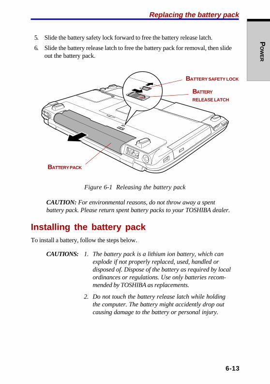
PO
WE
R
6-13
5. Slide the battery safety lock forward to free the battery release latch.
6. Slide the battery release latch to free the battery pack for removal, then slideout the battery pack.
Figure 6-1 Releasing the battery pack
CAUTION: For environmental reasons, do not throw away a spentbattery pack. Please return spent battery packs to your TOSHIBA dealer.
Installing the battery packTo install a battery, follow the steps below.
CAUTIONS: 1. The battery pack is a lithium ion battery, which canexplode if not properly replaced, used, handled ordisposed of. Dispose of the battery as required by localordinances or regulations. Use only batteries recom-mended by TOSHIBA as replacements.
2. Do not touch the battery release latch while holdingthe computer. The battery might accidently drop outcausing damage to the battery or personal injury.
Replacing the battery pack
BATTERY PACK
BATTERY
RELEASE LATCH
BATTERY SAFETY LOCK
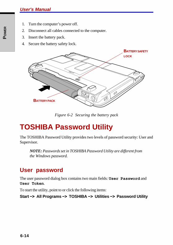
6-14
User's ManualP
OW
ER
1. Turn the computer’s power off.
2. Disconnect all cables connected to the computer.
3. Insert the battery pack.
4. Secure the battery safety lock.
Figure 6-2 Securing the battery pack
TOSHIBA Password UtilityThe TOSHIBA Password Utility provides two levels of password security: User andSupervisor.
NOTE: Passwords set in TOSHIBA Password Utility are different fromthe Windows password.
User passwordThe user password dialog box contains two main fields: User Password andUser Token .
To start the utility, point to or click the following items:
Start −> −> −> −> −> All Programs −> −> −> −> −> TOSHIBA −>−>−>−>−> Utilities −>−>−>−>−> Password Utility
BATTERY PACK
BATTERY SAFETY
LOCK

PO
WE
R
6-15
User Password field
❖❖❖❖❖ Set (button)
Click this button to register a password of up to 50 characters. After a pass-word is set, you will be prompted to enter it when you start the computer.
NOTE: After you set the password, a dialog box will be displayed askingwhether you want to save it to a diskette or other media. If you forget thepassword, you can open the password file on another computer. Be sureto keep the media in a safe place.
❖❖❖❖❖ Delete (button)
Click this button to delete a registered password. Before you can delete apassword, you must first enter the current password correctly or insert a propertoken.
❖❖❖❖❖ Change (button)
Click this button to change a registered password. Before you can change apassword, you must first enter the current password correctly or insert a propertoken.
❖❖❖❖❖ Owner String (text box)
You can use this box to associate text with the password. After you enter text,click Apply or OK. The text will be displayed when you are prompted to enter apassword. You can enter up to five lines of 40 characters in each line. Anyentry exceeding that limit will be ignored.
User Token field
❖❖❖❖❖ Create (button)
You can use an SD card token, instead of entering the password. After youhave registered a password, insert an SD card and click Create . You can usean SD card of any capacity, but it must be formatted correctly.
If an unformatted card or one with an incompatible format is inserted, you willbe prompted to format it with a tool named TOSHIBA SD Memory Card Format.To start the format tool, point to or click the following items:
Start −> −> −> −> −> All Programs −> −> −> −> −> TOSHIBA −> −> −> −> −> Utilities −> −> −> −> −> SD Memory CardFormat
CAUTION: When you format an SD Memory card, all data will bedeleted. Be sure to save data on the card to other media before youformat the card.
TOSHIBA Password Utility

6-16
User's ManualP
OW
ER
❖❖❖❖❖ Disable (button)
Click this button to invalidate the token. You cannot revalidate old tokens, butyou can use the same SD cards to create new tokens.
Supervisor passwordTo set a supervisor password, follow the steps below.
1. Click Start .
2. Click Run.
3. Enter the following: C:\Program Files\Toshiba\WindowsUtilities\SVPWTool\TOSPU.EXE
NOTE: If you set a supervisor password, some functions might berestricted when a user logs on with the user password.
This utility lets you do the following:
❖❖❖❖❖ Register, delete or change the supervisor password.
❖❖❖❖❖ Create or invalidate a supervisor token
NOTE: This function in the TOSHIBA Password Utility lets you invali-date only supervisor tokens or all tokens, including user and supervisortokens.
❖❖❖❖❖ Specify restrictions for general users.
Starting the computer by passwordIf you registered a password, there are two ways to start the computer:
❖❖❖❖❖ Insert a token before you turn on the computer. The computer will startnormally, without displaying a password prompt.
❖❖❖❖❖ Enter the password manually.
NOTE: The password is necessary only if the computer was shut down inboot mode. It is not needed in Hibernation or Standby mode.

PO
WE
R
6-17
To enter a password manually, follow these steps:
1. Turn on the power as described in Chapter 3, Getting Started. The followingmessage will be displayed:
Figure 6-3 BIOS password window
2. Follow the on-screen prompts to enter the password.
NOTE: If you enter the password incorrectly three times in a row, thecomputer shuts off. In this case, you must turn the computer back on toretry password entry.
Power-up modesThe computer has the following power-up modes:
❖❖❖❖❖ Boot: Computer shuts down without saving data. Always save your workbefore you turn the computer off in boot mode.
❖❖❖❖❖ Hibernation: Data in memory is saved to the hard disk.
❖❖❖❖❖ Standby: Data is maintained in the computer’s main memory.
NOTE: Refer also to the sections Turning on the power and Turning offthe power in Chapter 3, Getting Started.
Power-up modes

6-18
User's ManualP
OW
ER
Windows utilitiesYou can specify the setting in TOSHIBA Power Saver.
Hot keysYou can use hot keys Fn + F3 to enter Standby mode and Fn + F4 to enterHibernation. See Chapter 5, The Keyboard, for details.
Panel power on/offYou can set up your computer so that power turns off automatically when you closethe display panel. When you open the panel, power turns on in Standby orHibernation mode but not in boot mode.
NOTE: If the panel power off function is enabled and you use Shut downWindows, do not close the display until the shut down function iscompleted.
System Auto OffThis feature turns the system off automatically if it is not used for a set duration.The system shuts down in Standby mode or Hibernation mode in Windows.
7-1
HW
SE
TU
P
Chapter 7
HW SetupThis chapter explains how to use TOSHIBA HW Setup program to configure yourcomputer. TOSHIBA HW Setup lets you configure settings for General, Parallel/Printer, Display, Boot Priority, Keyboard, CPU and LAN .
Accessing HW SetupTo run HW Setup, click start , click Control Panel and select TOSHIBA HWSetup .
HW Setup windowThe HW Setup window contains the following tabs: General, Parallel/Printer,Display, Boot Priority, Keyboard, CPU and LAN.
There are also three buttons: OK, Cancel and Apply .
OK Accepts your changes and closes the HW Setup window.
Cancel Closes the window without accepting your changes.
Apply Accepts all your changes without closing the HW Setupwindow.
GeneralThis window displays the BIOS version and contains two buttons: Default andAbout .
Setup
This field displays BIOS Version and date.
Default
Click Default to return all HW Setup values to the factory settings.
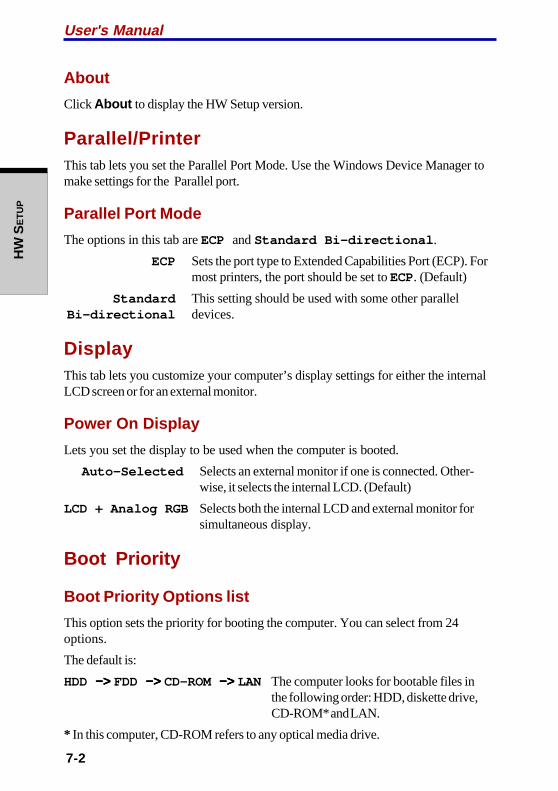
User's Manual
7-2
HW
SE
TU
P
About
Click About to display the HW Setup version.
Parallel/PrinterThis tab lets you set the Parallel Port Mode. Use the Windows Device Manager tomake settings for the Parallel port.
Parallel Port Mode
The options in this tab are ECP and Standard Bi-directional .
ECP Sets the port type to Extended Capabilities Port (ECP). Formost printers, the port should be set to ECP. (Default)
Standard This setting should be used with some other parallelBi-directional devices.
DisplayThis tab lets you customize your computer’s display settings for either the internalLCD screen or for an external monitor.
Power On Display
Lets you set the display to be used when the computer is booted.
Auto-Selected Selects an external monitor if one is connected. Other-wise, it selects the internal LCD. (Default)
LCD + Analog RGB Selects both the internal LCD and external monitor forsimultaneous display.
Boot Priority
Boot Priority Options list
This option sets the priority for booting the computer. You can select from 24options.
The default is:
HDD −> −> −> −> −> FDD −> −> −> −> −> CD-ROM −> −> −> −> −> LAN The computer looks for bootable files inthe following order: HDD, diskette drive,CD-ROM* and LAN.
* In this computer, CD-ROM refers to any optical media drive.

7-3
HW
SE
TU
P
Temporarily changing the priority
To temporarily change the boot drive, follow the steps below.
1. Hold down F12 and boot the computer.
2. A menu will be displayed with the following icons: Hard Drive, RemovableDevices, CD/DVD-ROM Drive and Network Boot. The selected boot devicewill be effective only for the next boot.
3. Use the up/down cursor keys to highlight the boot device you want and pressEnter .
NOTES: 1. If a supervisor password is set, the menu above does notappear when you use the user password to start thecomputer.
2. The selection method above does not change the bootpriority settings in HW Setup.
3. If you press a key other than one of those above or if theselected device is not installed, the system will boot accordingto the current setting in HW Setup.
4. Support of PC (ATA) card boot is guaranteed only forTOSHIBA PC card HDDs.
5. A PC (ATA) card takes the position of HDD in the BootPriority Options list, if the card is set up as the boot device inBIOS setup.
Built-in LAN disabled
Under certain conditions, LAN will automatically be moved to the last item in theboot priority list.
If you disable Built-in LAN in HW Setup, LAN will become the last item the next timeyou start the computer. For example:
1. Boot priority option is set to HDD −> −> −> −> −> LAN −> −> −> −> −> FDD −> −> −> −> −> CD-ROM.
2. You disable Built-in LAN in HW Setup and restart the computer.
3. The boot priority option setting will automatically change to HDD −> −> −> −> −> FDD−> −> −> −> −> CD-ROM −> −> −> −> −> LAN .
If you enable Built-in LAN and change the boot priority setting, LAN will remain inthe last position the next time you start the computer. Your selected boot prioritywill become effective from the second time you start the computer.
HW Setup window
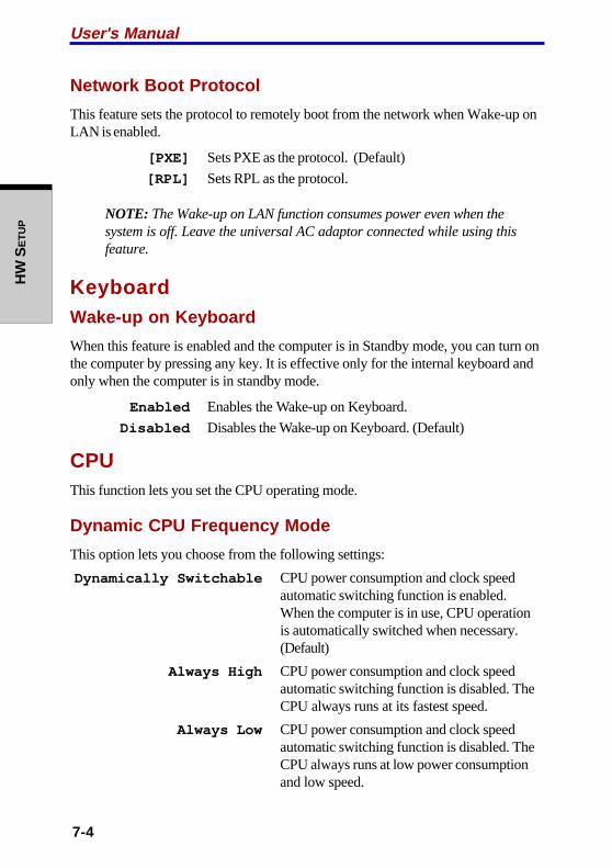
User's Manual
7-4
HW
SE
TU
P
Network Boot Protocol
This feature sets the protocol to remotely boot from the network when Wake-up onLAN is enabled.
[PXE] Sets PXE as the protocol. (Default)
[RPL] Sets RPL as the protocol.
NOTE: The Wake-up on LAN function consumes power even when thesystem is off. Leave the universal AC adaptor connected while using thisfeature.
KeyboardWake-up on Keyboard
When this feature is enabled and the computer is in Standby mode, you can turn onthe computer by pressing any key. It is effective only for the internal keyboard andonly when the computer is in standby mode.
Enabled Enables the Wake-up on Keyboard.
Disabled Disables the Wake-up on Keyboard. (Default)
CPUThis function lets you set the CPU operating mode.
Dynamic CPU Frequency Mode
This option lets you choose from the following settings:
Dynamically Switchable CPU power consumption and clock speedautomatic switching function is enabled.When the computer is in use, CPU operationis automatically switched when necessary.(Default)
Always High CPU power consumption and clock speedautomatic switching function is disabled. TheCPU always runs at its fastest speed.
Always Low CPU power consumption and clock speedautomatic switching function is disabled. TheCPU always runs at low power consumptionand low speed.
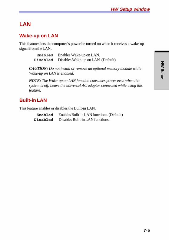
7-5
HW
SE
TU
P
LAN
Wake-up on LAN
This features lets the computer’s power be turned on when it receives a wake-upsignal from the LAN.
Enabled Enables Wake-up on LAN.Disabled Disables Wake-up on LAN. (Default)
CAUTION: Do not install or remove an optional memory module whileWake-up on LAN is enabled.
NOTE: The Wake-up on LAN function consumes power even when thesystem is off. Leave the universal AC adaptor connected while using thisfeature.
Built-in LAN
This feature enables or disables the Built-in LAN.
Enabled Enables Built-in LAN functions. (Default)Disabled Disables Built-in LAN functions.
HW Setup window

User's Manual
7-6
HW
SE
TU
P

8-1
OP
TIO
NA
L DE
VIC
ES
Chapter 8
Optional DevicesOptional devices can expand the computer’s capabilities and its versatility. Thischapter describes connection or installation of the following devices, which areavailable from your TOSHIBA dealer:
Cards/memory
❖❖❖❖❖ PC cards
❖❖❖❖❖ SD cards
❖❖❖❖❖ Memory expansion
Power devices
❖❖❖❖❖ Battery packs
❖❖❖❖❖ Universal AC adaptor
Peripheral devices
❖❖❖❖❖ USB FDD kit
❖❖❖❖❖ External monitor
❖❖❖❖❖ TV
❖❖❖❖❖ Parallel printer
❖❖❖❖❖ i.LINK (IEEE1394)
Other
❖❖❖❖❖ Security lock

User's Manual
8-2
OP
TIO
NA
L D
EV
ICE
S
PC cardsThe computer is equipped with a PC card expansion slot that can accommodate one5 mm Type II card. Any PC card that meets industry standards (manufactured byTOSHIBA or other vendor) can be installed. The slot supports 32-bit cards,including CardBus PC cards, which provide superior performance for the greaterdemands of multimedia. It also supports 16-bit PC cards, including PC card 16’smultifunction card.
Inserting a PC cardThe PC card connector is located on the left side of the computer.
Windows’ hot-install feature lets you insert PC cards while the computer’s power ison.
NOTE: Do not insert a PC card while the computer is in standby orhibernation mode. Some cards might not work properly.
To insert a PC card, follow the steps below.
1. Insert the PC card.
2. Press gently to ensure a firm connection.
Figure 8-1 Inserting a PC card
3. Refer to the card’s documentation and check the configuration in Windows tomake sure it is appropriate for your card.
PC CARD

8-3
OP
TIO
NA
L DE
VIC
ES
Removing a PC cardTo remove the PC card, follow the steps below.
1. Click the Safety Remove Hardware icon on the Task Bar.
2. Click PC card .
3. Press the PC card eject button to extend it.
4. Press the extended eject button to pop the card out slightly.
5. Grasp the PC card and remove it.
Figure 8-2 Removing a PC card
PC cards
EJECT BUTTON
PC CARD

User's Manual
8-4
OP
TIO
NA
L D
EV
ICE
S
SD cardsThe computer is equipped with an SD card slot that can accommodate SecureDigital flash memory cards with various memory capacities. SD cards let you easilytransfer data from devices, such as digital cameras and Personal Digital Assistants,that use SD card flash-memory. The cards have a high level of security and copyprotection features. The slot cannot accommodate MultiMedia cards.
CAUTION: Keep foreign objects out of the SD card slot. A pin or similarobject can damage the computer’s circuitry.
NOTE: SD memory cards comply with SDMI (Secure Digital MusicInitiative), which is a technology adopted to prevent unlawful copy orplayback of digital music. For this reason, you cannot copy or playbackprotected material on another computer or other device. You may not usethe reproduction of any copyrighted material except for your personalenjoyment.
Inserting an SD cardTo insert an SD card, follow the steps below.
1. Insert the SD card.
2. Press it gently to ensure a firm connection.
Figure 8-3 Inserting an SD card
CAUTION: Make sure the SD card is oriented properly before you insert it.
SD CARD

8-5
OP
TIO
NA
L DE
VIC
ES
SD cards
Removing an SD cardTo remove an SD card, follow the steps below.
1. Click the Safety Remove Hardware icon on the Task Bar.
2. Point to SD card and click.
3. Push in the card and release it to pop the card out slightly.
4. Grasp the card and remove it.
Figure 8-4 Removing an SD card
CAUTIONS: 1. Make sure the SD card indicator is out before youremove the card or turn off the computer’s power. Ifyou remove the card or turn off the power while thecomputer is accessing the card you may lose data ordamage the card.
2. Do not remove an SD card while the computer is inStandby or Hibernation mode. The computer couldbecome unstable or data in the SD card could be lost.
SD card care
CAUTION: Set the write-protect switch to the lock position, if you do notwant to record data.
1. Do not write to an SD card if the battery power is low. Low power could affectwriting accuracy.
2. Do not remove an SD card while read/write is in progress.
SD CARD
SD CARD
INDICATOR

User's Manual
8-6
OP
TIO
NA
L D
EV
ICE
S
3. The SD card is designed so that it can be inserted only one way. Do not try toforce the card into the slot.
4. Do not leave an SD card partially inserted in the slot. Press the SD card untilyou hear it click into place.
5. Do not twist or bend SD cards.
6. Do not expose SD cards to liquids or store in humid areas or lay them close tocontainers of liquid.
7. After using an SD card, return it to its case.
8. Do not touch the metal part or expose it to liquids or let it get dirty.
Memory expansionYou can install additional memory in the computer’s memory socket to increase theamount of RAM. This section describes how to install and remove a memorymodule.
CAUTIONS: 1. Use only memory modules approved by TOSHIBA.
2. Do not try to install or remove a memory module underthe following conditions. You can damage thecomputer and the module. Also, data will be lost.
a. The computer is turned on.
b. The computer was shut down using Standby modeor Hibernation mode.
c. Wake-up on LAN is enabled.
3. Some memory modules can be physically installed butare not compatible with the computer. In this case, thecomputer will issue a warning. When you turn on thepower, a series of short beeps will sound in the patternof one, three, three, one. Shut down the power andremove the incompatible module.
4. Be careful not to let screws or other foreign matter fallinto the computer. It could cause malfunction orelectric shock.
NOTE: Use a 0-bit, Phillips screwdriver to loosen the screw. Use of anincorrect screwdriver can damage the screw head.

8-7
OP
TIO
NA
L DE
VIC
ES
Installing memory moduleThere are slots for two memory modules, one over the other. The procedures are thesame for installing either module.
1. Set the computer to boot mode and turn the computer’s power off. Make surethe Power indicator is off.
2. Remove universal AC adaptor and all cables connected to the computer.
3. Turn the computer upside down and remove the battery pack. Refer toReplacing the battery pack section in Chapter 6, Power, for details.
4. Loosen one screw securing the memory module cover and lift off the cover.
Figure 8-5 Removing the memory module cover
Memory expansion
MEMORY MODULE COVERSCREW
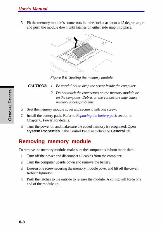
User's Manual
8-8
OP
TIO
NA
L D
EV
ICE
S
5. Fit the memory module’s connectors into the socket at about a 45 degree angleand push the module down until latches on either side snap into place.
Figure 8-6 Seating the memory module
CAUTIONS: 1. Be careful not to drop the screw inside the computer.
2. Do not touch the connectors on the memory module oron the computer. Debris on the connectors may causememory access problems.
6. Seat the memory module cover and secure it with one screw.
7. Install the battery pack. Refer to Replacing the battery pack section inChapter 6, Power, for details.
8. Turn the power on and make sure the added memory is recognized. OpenSystem Properties in the Control Panel and click the General tab.
Removing memory moduleTo remove the memory module, make sure the computer is in boot mode then:
1. Turn off the power and disconnect all cables from the computer.
2. Turn the computer upside down and remove the battery.
3. Loosen one screw securing the memory module cover and lift off the cover.Refer to figure 8-5.
4. Push the latches to the outside to release the module. A spring will force oneend of the module up.

8-9
OP
TIO
NA
L DE
VIC
ES
Universal AC adaptor
5. Grasp the module by the sides and pull it out.
CAUTIONS: 1. If you use the computer for a long time, the memorymodules and the circuits located close to the memorymodules will become hot. In this case, let them cool toroom temperature before you replace them.
2. Do not touch the connectors on the memory module oron the computer. Debris on the connectors may causememory access problems.
Figure 8-7 Removing the memory module
6. Seat the memory module cover and secure it with one screw.
Battery packsYou can increase the portability of the computer with additional standard or high-capacity battery packs. If you’re away from an AC power source and your batteryruns low, you can replace it with a freshly charged battery. Refer to Chapter 6,Power.
Universal AC adaptorIf you frequently transport the computer between different sites such as your homeand office, purchasing a universal AC adaptor for each location will reduce theweight and bulk of your carrying load.
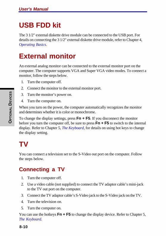
User's Manual
8-10
OP
TIO
NA
L D
EV
ICE
S
USB FDD kitThe 3 1/2" external diskette drive module can be connected to the USB port. Fordetails on connecting the 3 1/2" external diskette drive module, refer to Chapter 4,Operating Basics.
External monitorAn external analog monitor can be connected to the external monitor port on thecomputer. The computer supports VGA and Super VGA video modes. To connect amonitor, follow the steps below.
1. Turn the computer off.
2. Connect the monitor to the external monitor port.
3. Turn the monitor’s power on.
4. Turn the computer on.
When you turn on the power, the computer automatically recognizes the monitorand determines whether it is color or monochrome.
To change the display settings, press Fn + F5. If you disconnect the monitorbefore you turn the computer off, be sure to press Fn + F5 to switch to the internaldisplay. Refer to Chapter 5, The Keyboard, for details on using hot keys to changethe display setting.
TVYou can connect a television set to the S-Video out port on the computer. Followthe steps below.
Connecting a TV1. Turn the computer off.
2. Use a video cable (not supplied) to connect the TV adaptor cable’s mini-jackto the TV out port on the computer.
3. Connect the TV adaptor cable’s S-Video jack to the S-Video jack on the TV.
4. Turn the television on.
5. Turn the computer on.
You can use the hotkeys Fn + F5 to change the display device. Refer to Chapter 5,The Keyboard.
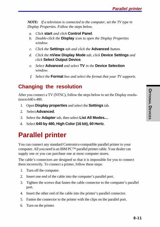
8-11
OP
TIO
NA
L DE
VIC
ES
NOTE: If a television is connected to the computer, set the TV type inDisplay Properties. Follow the steps below.
a. Click start and click Control Panel .b. Double-click the Display icon to open the Display Properties
window.
c. Click the Settings tab and click the Advanced button.
d. Click the nView Display Mode tab, click Device Settings andclick Select Output Device .
e. Select Advanced and select TV in the Device Selectionwindow.
f. Select the Format box and select the format that your TV supports.
Changing the resolutionAfter you connect a TV (NTSC), follow the steps below to set the Display resolu-tion to 640 x 480.
1. Open Display properties and select the Settings tab.
2. Select Advanced .
3. Select the Adapter tab, then select List All Modes... .
4. Select 640 by 480, High Color (16 bit), 60 Hertz .
Parallel printerYou can connect any standard Centronics-compatible parallel printer to yourcomputer. All you need is an IBM PC™ parallel printer cable. Your dealer cansupply one or you can purchase one at most computer stores.
The cable’s connectors are designed so that it is impossible for you to connectthem incorrectly. To connect a printer, follow these steps:
1. Turn off the computer.
2. Insert one end of the cable into the computer’s parallel port.
3. Tighten the screws that fasten the cable connector to the computer’s parallelport.
4. Insert the other end of the cable into the printer’s parallel connector.
5. Fasten the connector to the printer with the clips on the parallel port.
6. Turn on the printer.
Parallel printer

User's Manual
8-12
OP
TIO
NA
L D
EV
ICE
S
7. Turn on the computer.
8. Start the HW Setup program. Refer to Chapter 7, HW Setup.
9. Select the Parallel/Printer tab from the TOSHIBA HW Setupwindow.
10. Set the Parallel Port Mode and press OK.
11. Choose Reboot for the change to take effect.
12. Select the printer in Windows Add Print Wizard. To access the Add PrintWizard utility, click Start , point to Settings , click Printers and doubleclick the Add Printer icon.
i.LINK (IEEE1394)i.LINK (IEEE1394) is used for high-speed data transfer for a range of compatibledevices such as
❖❖❖❖❖ Digital video cameras
❖❖❖❖❖ Hard disk drives
❖❖❖❖❖ MO drives
❖❖❖❖❖ CD-RW drives
NOTE: i.LINK uses a four-pin connector, which does not carryelectric current. External devices will need their own power supply.
Precautions❖❖❖❖❖ Make a backup of your data before transferring it to the computer. There is a
possibility that the original data will be damaged. There is a particular risk thatsome frames will be deleted in the case of digital video transfer. TOSHIBAassumes no liability for such loss of data.
❖❖❖❖❖ Do not transfer data in areas where static electricity is easily generated or inareas subjected to electronic noise. Data can be destroyed.
❖❖❖❖❖ If you are transferring data through an IEEE1394 hub, do not connect ordisconnect other devices from the hub during data transfer. There is a likeli-hood that data will be damaged. Connect all devices to the hub before you turnon the computer’s power.
❖❖❖❖❖ You may not use any copyrighted video or music data copied from a videocamera except for your personal enjoyment.

8-13
OP
TIO
NA
L DE
VIC
ES
❖❖❖❖❖ If you connect/disconnect an i.LINK device to/from another i.LINK device thatis currently exchanging data with the computer, data frames might be dropped.
❖❖❖❖❖ Make sure data transfer has ended or turn off the computer, before you:
• Connect/disconnect an i.LINK device to/from the computer.
• Connect/disconnect an i.LINK device to/from another i.LINK device that isconnected to the computer.
Connecting1. Make sure the connectors are properly aligned and plug the i.LINK (IEEE1394)
cable into the computer.
2. Plug the other end of the cable into the device.
Note the following when you use i.LINK:
❖❖❖❖❖ You may need to install drivers for your i.LINK devices.
❖❖❖❖❖ Not all i.LINK devices have been tested. Therefore, compatibility with all i.LINKdevices cannot be guaranteed.
❖❖❖❖❖ Use S100, S200 or S400 cables no longer than three meters.
❖❖❖❖❖ Some devices might not support standby or automatic off functions.
❖❖❖❖❖ Do not connect or disconnect an i.LINK device while it is using an applicationor when the computer is automatically shutting it down to save power. Datamight be destroyed.
Disconnecting1. Open the Safety Remove Hardware icon on the System tray.
2. Point to i.LINK (IEEE1394) device and click.
3. Disconnect the cable from the computer then from the i.LINK device.
NOTE: Refer also to the documentation that came with your i.LINKdevice.
i.LINK (IEEE1394)

User's Manual
8-14
OP
TIO
NA
L D
EV
ICE
S
Security lockA security lock enables you to anchor your computer to a desk or other heavyobject to help prevent unauthorized removal of the computer.
Attach one end of a cable to the desk and the other end to the security lock slot onthe right side of the computer.
Figure 8-8 Security lock
9-1
TR
OU
BLE
SH
OO
TIN
G
Chapter 9
TroubleshootingTOSHIBA designed the computer for durability. However, should problems occur,following the procedures in this chapter can help to determine the cause.
All readers should become familiar with this chapter. Knowing what might go wrongcan help prevent problems from occurring.
Problem solving processResolving problems will be much easier if you observe the following guidelines:
❖❖❖❖❖ Stop immediately when you recognize a problem exists. Further action mayresult in data loss or damage. You may destroy valuable problem-relatedinformation that can help solve the problem.
❖❖❖❖❖ Observe what is happening. Write down what the system is doing and whatactions you performed immediately before the problem occurred. If you have aprinter attached, print a copy of the screen using PrtSc SysReq .
The questions and procedures offered in this chapter are meant as a guide, they arenot definitive problem solving techniques. Many problems can be solved simply,but a few may require help from your dealer. If you find you need to consult yourdealer or others, be prepared to describe the problem in as much detail as possible.
Preliminary checklistConsider the simplest solution first. The items in this checklist are easy to fix and yetcan cause what appears to be a serious problem.
❖❖❖❖❖ Make sure you turn on all peripheral devices before you turn on the computer.This includes your printer and any other external device you are using.
❖❖❖❖❖ Before you attach an external device, turn the computer off. When you turn thecomputer back on it recognizes the new device.
❖❖❖❖❖ Make sure all options are set properly in the setup program.
❖❖❖❖❖ Check all cables. Are they correctly and firmly attached? Loose cables cancause signal errors.
❖❖❖❖❖ Inspect all connecting cables for loose wires and all connectors for loose pins.

User's ManualT
RO
UB
LES
HO
OT
ING
9-2
❖❖❖❖❖ Check that your diskette or CD/DVD-ROM is correctly inserted and that thediskette’s write protect tab is correctly set.
Make notes of your observations and keep them in a permanent error log. This willhelp you describe your problems to your dealer. If a problem recurs, the log will helpyou identify the problem faster.
Analyzing the problemSometimes the system gives clues that can help you identify why it is malfunction-ing. Keep the following questions in mind:
❖❖❖❖❖ Which part of the system is not operating properly: keyboard, diskette drives,hard disk drive, optical media drive, display. Each device produces differentsymptoms.
❖❖❖❖❖ Is the operating system configuration set properly? Check the configurationoptions.
❖❖❖❖❖ What appears on the display screen? Does it display any messages or randomcharacters? Print a copy of the screen if you have a printer attached. Look upthe messages in the software and operating system documentation. Check thatall connecting cables are correctly and firmly attached. Loose cables can causeerroneous or intermittent signals.
❖❖❖❖❖ Do any indicators light? Which ones? What color are they? Do they stay on orblink? Write down what you see.
❖❖❖❖❖ Do you hear any beeps? How many? Are they long or short? Are they highpitched or low? Is the computer making any unusual noises? Write down whatyou hear.
Record your observations so you can describe them to your dealer.
Software The problems may be caused by your software or disk. Ifyou cannot load a software package, the media may bedamaged or the program might be corrupted. Try loadinganother copy of the software.
If an error message appears while you are using a softwarepackage, check the software documentation. Thesedocuments usually include a problem solving section or asummary of error messages.
Next, check any error messages in the OS documentation.

9-3
TR
OU
BLE
SH
OO
TIN
G
Hardware If you cannot find a software problem, check your hard-ware. First run through the items in the preliminarychecklist above. If you still cannot correct the problem, tryto identify the source. The next section provides checklistsfor individual components and peripherals.
Hardware and system checklistThis section discusses problems caused by your computer’s hardware or attachedperipherals. Basic problems may occur in the following areas:
❖❖❖❖❖ System start-up ❖❖❖❖❖ PC card
❖❖❖❖❖ Self test ❖❖❖❖❖ Infrared port
❖❖❖❖❖ Power ❖❖❖❖❖ Pointing device
❖❖❖❖❖ Password ❖❖❖❖❖ USB
❖❖❖❖❖ Keyboard ❖❖❖❖❖ Memory expansion
❖❖❖❖❖ LCD panel ❖❖❖❖❖ Sound system
❖❖❖❖❖ Hard disk drive ❖❖❖❖❖ Monitor
❖❖❖❖❖ CD-RW/DVD-ROM drive ❖❖❖❖❖ Modem
❖❖❖❖❖ DVD-R/-RW drive ❖❖❖❖❖ LAN
❖❖❖❖❖ DVD Multi drive ❖❖❖❖❖ Wireless LAN
❖❖❖❖❖ Diskette drive ❖❖❖❖❖ TV output signal
❖❖❖❖❖ SD card ❖❖❖❖❖ Printer
❖❖❖❖❖ i.LINK (IEEE1394)
System start-upWhen the computer does not start properly, check the following items:
❖❖❖❖❖ Self Test
❖❖❖❖❖ Power Sources
❖❖❖❖❖ Power-on Password
Hardware and system checklist
User's ManualT
RO
UB
LES
HO
OT
ING
9-4
Self testWhen the computer starts up, the self test will be run automatically, and thefollowing will be displayed:
In Touch with TomorrowTOSHIBA
This message remains on the screen for a few seconds.
If the self test is successful, the computer tries to load the operating system.Depending on how the Boot Priority is set in the TOSHIBA HW Setup program.
If any of the following conditions are present, the self test failed:
❖❖❖❖❖ The computer stops and does not proceed to display information or messagesexcept the TOSHIBA logo.
❖❖❖❖❖ Random characters appear on the screen, and the system does not functionnormally.
❖❖❖❖❖ The screen displays an error message.
Turn off the computer and check all cable connections as well as PC card andmemory module connections. If the test fails again, contact your dealer.
PowerWhen the computer is not plugged into an AC outlet, the battery pack is the primarypower source. However, your computer has a number of other power resources,including intelligent power supply, Real Time Clock battery. These resources areinterrelated and any one could affect apparent power problems. This sectionprovides check lists for AC power and the battery. If you cannot resolve a problemafter following them, the cause could lie with another power resource. In such case,contact your dealer.

9-5
TR
OU
BLE
SH
OO
TIN
G
Overheating power down
If the computer’s internal temperature becomes too high, the computer will automati-cally shut down.
Problem Procedure
Computer shuts down Leave the computer off until the computerand DC IN indicator reaches room temperature, then turn it back on.flashes orange If the computer is still too warm, the DC IN
indicator will continue blinking when you turn onthe power. Let it cool longer and try again.
If the computer has reached room temperatureand still does not start, or if it starts but shutsdown quickly, contact your dealer.
AC power
If you have trouble turning on the computer with the universal AC adaptor con-nected, check the DC IN indicator. Refer to Chapter 6, Power, for more information.
Problem Procedure
Universal AC adaptor Check the connections. Make sure the corddoesn’t power the is firmly connected to the computer and acomputer (DC IN power outlet.indicator does notglow blue)
Check the condition of the cord and terminals. Ifthe cord is frayed or damaged, replace it. If theterminals are soiled, wipe them with cotton or aclean cloth.
If the universal AC adaptor still does not power thecomputer, contact your dealer.
Hardware and system checklist
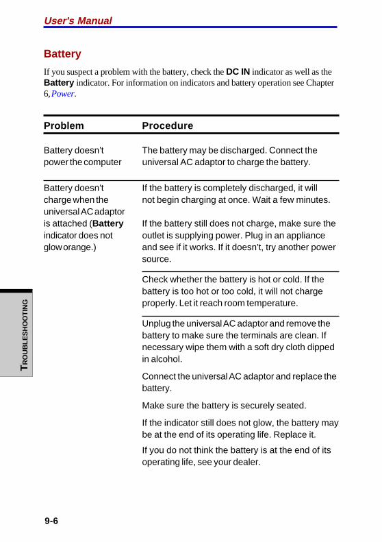
User's ManualT
RO
UB
LES
HO
OT
ING
9-6
Battery
If you suspect a problem with the battery, check the DC IN indicator as well as theBattery indicator. For information on indicators and battery operation see Chapter6, Power.
Problem Procedure
Battery doesn’t The battery may be discharged. Connect thepower the computer universal AC adaptor to charge the battery.
Battery doesn’t If the battery is completely discharged, it willcharge when the not begin charging at once. Wait a few minutes.universal AC adaptoris attached (Battery If the battery still does not charge, make sure theindicator does not outlet is supplying power. Plug in an applianceglow orange.) and see if it works. If it doesn’t, try another power
source.
Check whether the battery is hot or cold. If thebattery is too hot or too cold, it will not chargeproperly. Let it reach room temperature.
Unplug the universal AC adaptor and remove thebattery to make sure the terminals are clean. Ifnecessary wipe them with a soft dry cloth dippedin alcohol.
Connect the universal AC adaptor and replace thebattery.
Make sure the battery is securely seated.
If the indicator still does not glow, the battery maybe at the end of its operating life. Replace it.
If you do not think the battery is at the end of itsoperating life, see your dealer.
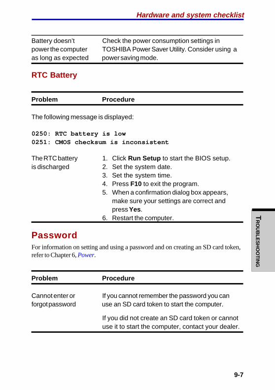
9-7
TR
OU
BLE
SH
OO
TIN
GHardware and system checklist
Battery doesn’t Check the power consumption settings inpower the computer TOSHIBA Power Saver Utility. Consider using aas long as expected power saving mode.
RTC Battery
Problem Procedure
The following message is displayed:
0250: RTC battery is low0251: CMOS checksum is inconsistent
The RTC battery 1. Click Run Setup to start the BIOS setup.is discharged 2. Set the system date.
3. Set the system time.4. Press F10 to exit the program.5. When a confirmation dialog box appears,
make sure your settings are correct andpress Yes.
6. Restart the computer.
PasswordFor information on setting and using a password and on creating an SD card token,refer to Chapter 6, Power.
Problem Procedure
Cannot enter or If you cannot remember the password you canforgot password use an SD card token to start the computer.
If you did not create an SD card token or cannotuse it to start the computer, contact your dealer.

User's ManualT
RO
UB
LES
HO
OT
ING
9-8
KeyboardKeyboard problems can be caused by your setup configuration. For more informa-tion refer to Chapter 5, The Keyboard.
Problem Procedure
Some letter keys Check that the numeric keypad overlay is notproduce numbers selected. Press Fn + F10 and try typing again.
Output to screen Make sure the software you are using is notis garbled remapping the keyboard. Remapping involves
reassigning the meaning of each key. See yoursoftware’s documentation.
If you are still unable to use the keyboard, consultyour dealer.
LCD panel
Problem Procedure
No display Press hot keys Fn + F5 to change the displaypriority, to make sure it is not set for an externalmonitor.
Markings appear on They might have come from contact with thethe LCD. keyboard, Touch Pad. Try wiping the LCD gently
with a clean dry cloth. If markings remain, useLCD cleaner. Be sure to let the LCD dry beforeclosing it.

9-9
TR
OU
BLE
SH
OO
TIN
G
Problems above Refer to your software’s documentation toremain unresolved determine if the software is causing theor other problems difficulty.occur
Contact your dealer if the problems continue.
Hard disk drive
Problem Procedure
Computer does not Check if a diskette is in the diskette drive or aboot from hard disk CD-ROM is in the optical media drive. Removedrive any diskette and/or CD-ROM and check Boot
priority. Refer to the Boot Priority section inChapter 7, HW Setup.
There may be a problem with your operatingsystem files. Refer to your OS documentation.
Slow performance Your files may be fragmented. Run SCANDISKand defragmenter to check the condition of yourfiles and disk. Refer to your OS documentation oronline HELP for information on running SCANDISKand the defragmenter.
As a last resort, reformat the hard disk. Then,reload the operating system and other files.
If problems persist, contact your dealer.
Hardware and system checklist

User's ManualT
RO
UB
LES
HO
OT
ING
9-10
CD-RW/DVD-ROM driveFor more information, refer to Chapter 4, Operating Basics.
Problem Procedure
You cannot access Make sure the drive’s drawer is securelya CD/DVD in the drive closed. Press gently until it clicks into place.
Open the drawer and make sure the CD/DVD isproperly seated. It should lie flat with the labelfacing up.
A foreign object in the drawer could block laserlight from reading the CD/DVD. Make sure thereis no obstruction. Remove any foreign object.
Check whether the CD/DVD is dirty. If it is, wipe itwith a clean cloth dipped in water or a neutralcleaner. See the Media care section in Chapter 4for details on cleaning.
Some CD/DVDs The software or hardware configuration mayrun correctly, but be causing a problem. Make sure theothers do not hardware configuration matches your software’s
needs. Check the CD/DVD’s documentation.
Check the type of CD/DVD you are using. Thedrive supports:
DVD-ROM: DVD-ROM, DVD-Video
CD-ROM: CD-DA, CD-Text, Photo CD (single/multi-session), CD-ROM Mode 1,Mode 2, CD-ROM XA Mode 2(Form1, Form2), Enhanced CD (CD-EXTRA), CD-G (Audio CD only),Addressing Method 2

9-11
TR
OU
BLE
SH
OO
TIN
G
Check the region code on the DVD. It mustmatch that on the CD-RW/DVD-ROM drive.Region codes are listed in the Optical mediadrives section in Chapter 2, The Grand Tour.
Cannot write correctly If you have trouble writing, make sure you areobserving the following precautions:
• Use only media recommended by TOSHIBA.• Do not use the mouse or keyboard during
writing.• Use only the software supplied with the
computer for recording.• Do not run or start other software during
writing.• Do not jar the computer during writing.• Do not connect/ disconnect external devices
or install/remove internal cards during writing.
If problems persist, contact your dealer.
DVD-R/-RW driveFor more information, refer to Chapter 4, Operating Basics.
Problem Procedure
You cannot access Make sure the drive’s drawer is securelya CD/DVD in the drive closed. Press gently until it clicks into place.
Open the drawer and make sure the CD/DVD isproperly seated. It should lie flat with the labelfacing up.
A foreign object in the drawer could block laserlight from reading the CD/DVD. Make sure thereis no obstruction. Remove any foreign object.
Hardware and system checklist
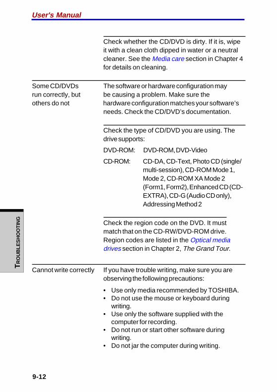
User's ManualT
RO
UB
LES
HO
OT
ING
9-12
Check whether the CD/DVD is dirty. If it is, wipeit with a clean cloth dipped in water or a neutralcleaner. See the Media care section in Chapter 4for details on cleaning.
Some CD/DVDs The software or hardware configuration mayrun correctly, but be causing a problem. Make sure theothers do not hardware configuration matches your software’s
needs. Check the CD/DVD’s documentation.
Check the type of CD/DVD you are using. Thedrive supports:
DVD-ROM: DVD-ROM, DVD-Video
CD-ROM: CD-DA, CD-Text, Photo CD (single/multi-session), CD-ROM Mode 1,Mode 2, CD-ROM XA Mode 2(Form1, Form2), Enhanced CD (CD-EXTRA), CD-G (Audio CD only),Addressing Method 2
Check the region code on the DVD. It mustmatch that on the CD-RW/DVD-ROM drive.Region codes are listed in the Optical mediadrives section in Chapter 2, The Grand Tour.
Cannot write correctly If you have trouble writing, make sure you areobserving the following precautions:
• Use only media recommended by TOSHIBA.• Do not use the mouse or keyboard during
writing.• Use only the software supplied with the
computer for recording.• Do not run or start other software during
writing.• Do not jar the computer during writing.

9-13
TR
OU
BLE
SH
OO
TIN
G
• Do not connect/ disconnect external devices orinstall/remove internal cards during writing.
If problems persist, contact your dealer.
DVD Multi driveFor more information, refer to Chapter 4, Operating Basics.
Problem Procedure
You cannot access Make sure the drive’s drawer is securelya CD/DVD in the drive closed. Press gently until it clicks into place.
Open the drawer and make sure the CD/DVD isproperly seated. It should lie flat with the labelfacing up.
A foreign object in the drawer could block laserlight from reading the CD/DVD. Make sure thereis no obstruction. Remove any foreign object.
Check whether the CD/DVD is dirty. If it is, wipeit with a clean cloth dipped in water or a neutralcleaner. See the Media care section in Chapter 4for details on cleaning.
Some CD/DVDs The software or hardware configuration mayrun correctly, but be causing a problem. Make sure theothers do not hardware configuration matches your software’s
needs. Check the CD/DVD’s documentation.
Hardware and system checklist

User's ManualT
RO
UB
LES
HO
OT
ING
9-14
Check the type of CD/DVD you are using. Thedrive supports:
DVD-ROM: DVD-ROM, DVD-Video
CD-ROM: CD-DA, CD-Text, Photo CD (single/multi-session), CD-ROM Mode 1,Mode 2, CD-ROM XA Mode 2(Form1, Form2), Enhanced CD (CD-EXTRA), CD-G (Audio CD only),Addressing Method 2
Check the region code on the DVD. It mustmatch that on the CD-RW/DVD-ROM drive.Region codes are listed in the Optical mediadrives section in Chapter 2, The Grand Tour.
Cannot write correctly If you have trouble writing, make sure you areobserving the following precautions:
• Use only media recommended by TOSHIBA.• Do not use the mouse or keyboard during
writing.• Use only the software supplied with the
computer for recording.• Do not run or start other software during
writing.• Do not jar the computer during writing.• Do not connect/ disconnect external devices
or install/remove internal cards during writing.
If problems persist, contact your dealer.

9-15
TR
OU
BLE
SH
OO
TIN
G
Diskette driveFor more information, refer to Chapter 4, Operating Basics.
Problem Procedure
Drive does not There may be a faulty cable connection. Checkoperate the connection to the computer and to the drive.
You cannot access Try another diskette. If you can access thethe external 3 1/2" diskette, the original diskette (not the drive) isdiskette drive probably causing the problem.
If problems persist, contact your dealer.
SD cardRefer also to Chapter 8, Optional Devices.
Problem Procedure
SD card Reseat the SD card to make sure it is firmlyerror occurs connected.
Check the card’s documentation.
You cannot write Make sure the card is not write protected.to an SD card
You cannot read Make sure the target file is on the SDa file Card inserted in the slot.
If problems persist, contact your dealer.
Hardware and system checklist

User's ManualT
RO
UB
LES
HO
OT
ING
9-16
PC cardRefer also to Chapter 8, Optional Devices.
Problem Procedure
PC card Reseat the PC card to make sure it iserror occurs firmly connected.
Make sure the connection between the externaldevice and the card is firm.
Check the card’s documentation.
If problems persist, contact your dealer.
Infrared portRefer also to the documentation for your IrDA compatible device and relatedsoftware.
Problem Procedure
Infrared devices do Make sure there is no obstruction blockingnot work as expected communication between the computer and the
target device.
If problems persist, contact your dealer.
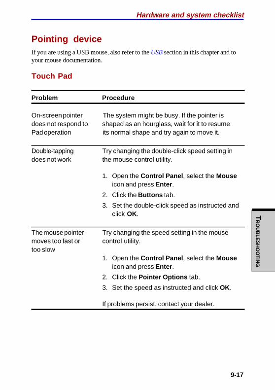
9-17
TR
OU
BLE
SH
OO
TIN
G
Pointing deviceIf you are using a USB mouse, also refer to the USB section in this chapter and toyour mouse documentation.
Touch Pad
Problem Procedure
On-screen pointer The system might be busy. If the pointer isdoes not respond to shaped as an hourglass, wait for it to resumePad operation its normal shape and try again to move it.
Double-tapping Try changing the double-click speed setting indoes not work the mouse control utility.
1. Open the Control Panel , select the Mouseicon and press Enter .
2. Click the Buttons tab.
3. Set the double-click speed as instructed andclick OK.
The mouse pointer Try changing the speed setting in the mousemoves too fast or control utility.too slow
1. Open the Control Panel , select the Mouseicon and press Enter .
2. Click the Pointer Options tab.
3. Set the speed as instructed and click OK.
If problems persist, contact your dealer.
Hardware and system checklist
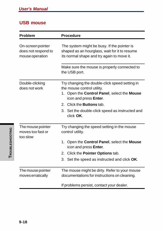
User's ManualT
RO
UB
LES
HO
OT
ING
9-18
USB mouse
Problem Procedure
On-screen pointer The system might be busy. If the pointer isdoes not respond to shaped as an hourglass, wait for it to resumemouse operation its normal shape and try again to move it.
Make sure the mouse is properly connected tothe USB port.
Double-clicking Try changing the double-click speed setting indoes not work the mouse control utility.
1. Open the Control Panel , select the Mouseicon and press Enter .
2. Click the Buttons tab.
3. Set the double-click speed as instructed andclick OK.
The mouse pointer Try changing the speed setting in the mousemoves too fast or control utility.too slow
1. Open the Control Panel , select the Mouseicon and press Enter .
2. Click the Pointer Options tab.
3. Set the speed as instructed and click OK.
The mouse pointer The mouse might be dirty. Refer to your mousemoves erratically documentations for instructions on cleaning.
If problems persist, contact your dealer.
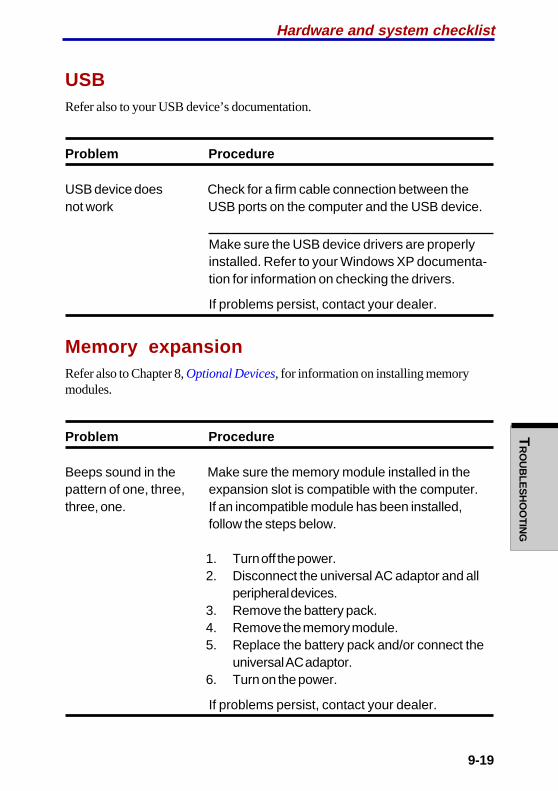
9-19
TR
OU
BLE
SH
OO
TIN
GHardware and system checklist
USBRefer also to your USB device’s documentation.
Problem Procedure
USB device does Check for a firm cable connection between thenot work USB ports on the computer and the USB device.
Make sure the USB device drivers are properlyinstalled. Refer to your Windows XP documenta-tion for information on checking the drivers.
If problems persist, contact your dealer.
Memory expansionRefer also to Chapter 8, Optional Devices, for information on installing memorymodules.
Problem Procedure
Beeps sound in the Make sure the memory module installed in thepattern of one, three, expansion slot is compatible with the computer.three, one. If an incompatible module has been installed,
follow the steps below.
1. Turn off the power.2. Disconnect the universal AC adaptor and all
peripheral devices.3. Remove the battery pack.4. Remove the memory module.5. Replace the battery pack and/or connect the
universal AC adaptor.6. Turn on the power.
If problems persist, contact your dealer.
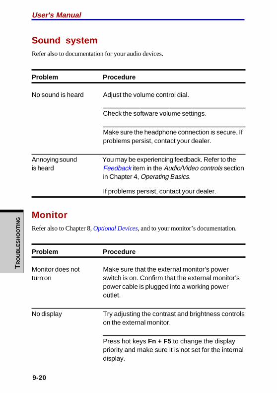
User's ManualT
RO
UB
LES
HO
OT
ING
9-20
Sound systemRefer also to documentation for your audio devices.
Problem Procedure
No sound is heard Adjust the volume control dial.
Check the software volume settings.
Make sure the headphone connection is secure. Ifproblems persist, contact your dealer.
Annoying sound You may be experiencing feedback. Refer to theis heard Feedback item in the Audio/Video controls section
in Chapter 4, Operating Basics.
If problems persist, contact your dealer.
MonitorRefer also to Chapter 8, Optional Devices, and to your monitor’s documentation.
Problem Procedure
Monitor does not Make sure that the external monitor’s powerturn on switch is on. Confirm that the external monitor’s
power cable is plugged into a working poweroutlet.
No display Try adjusting the contrast and brightness controlson the external monitor.
Press hot keys Fn + F5 to change the displaypriority and make sure it is not set for the internaldisplay.
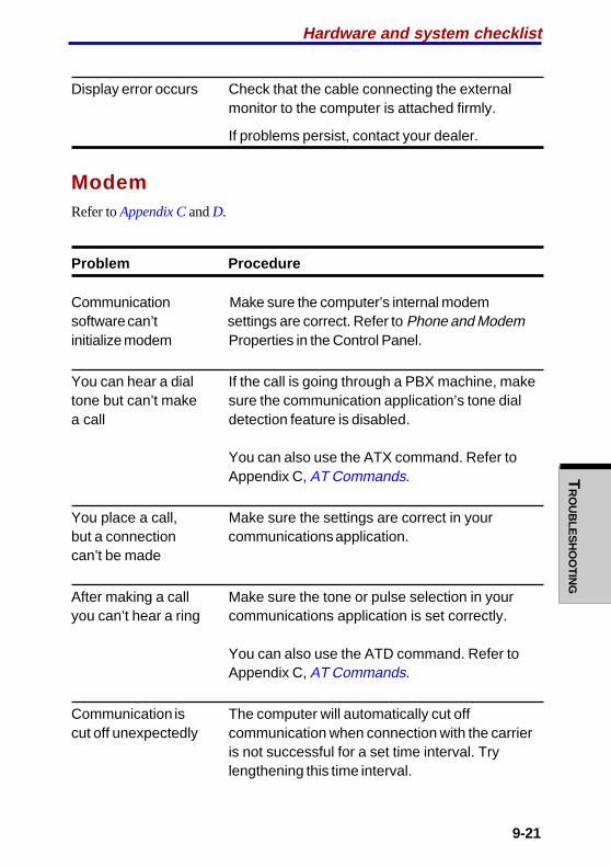
9-21
TR
OU
BLE
SH
OO
TIN
G
Display error occurs Check that the cable connecting the externalmonitor to the computer is attached firmly.
If problems persist, contact your dealer.
ModemRefer to Appendix C and D.
Problem Procedure
Communication Make sure the computer’s internal modemsoftware can’t settings are correct. Refer to Phone and Modeminitialize modem Properties in the Control Panel.
You can hear a dial If the call is going through a PBX machine, maketone but can’t make sure the communication application’s tone diala call detection feature is disabled.
You can also use the ATX command. Refer toAppendix C, AT Commands.
You place a call, Make sure the settings are correct in yourbut a connection communications application.can’t be made
After making a call Make sure the tone or pulse selection in youryou can’t hear a ring communications application is set correctly.
You can also use the ATD command. Refer toAppendix C, AT Commands.
Communication is The computer will automatically cut offcut off unexpectedly communication when connection with the carrier
is not successful for a set time interval. Trylengthening this time interval.
Hardware and system checklist
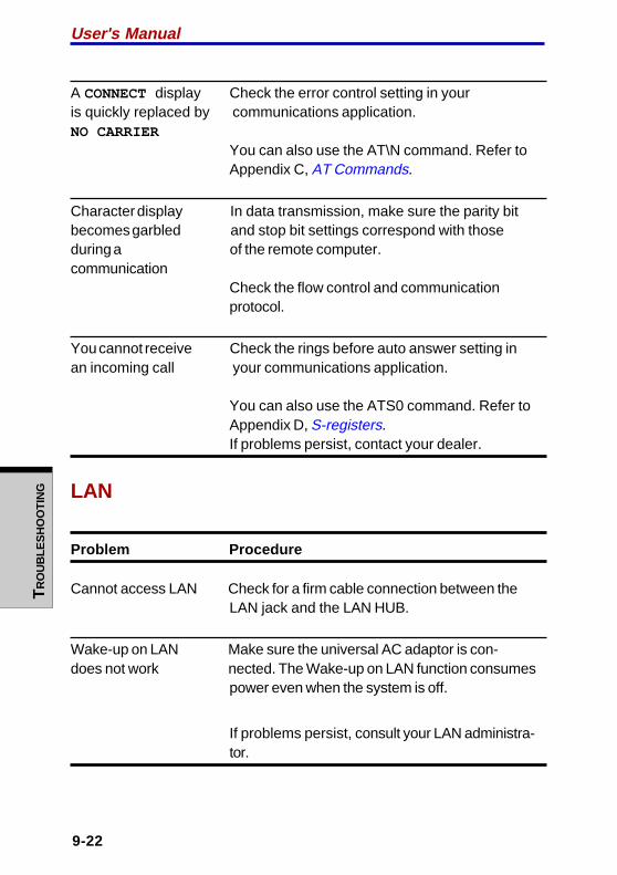
User's ManualT
RO
UB
LES
HO
OT
ING
9-22
A CONNECT display Check the error control setting in youris quickly replaced by communications application.NO CARRIER
You can also use the AT\N command. Refer toAppendix C, AT Commands.
Character display In data transmission, make sure the parity bitbecomes garbled and stop bit settings correspond with thoseduring a of the remote computer.communication
Check the flow control and communicationprotocol.
You cannot receive Check the rings before auto answer setting inan incoming call your communications application.
You can also use the ATS0 command. Refer toAppendix D, S-registers.If problems persist, contact your dealer.
LAN
Problem Procedure
Cannot access LAN Check for a firm cable connection between theLAN jack and the LAN HUB.
Wake-up on LAN Make sure the universal AC adaptor is con-does not work nected. The Wake-up on LAN function consumes
power even when the system is off.
If problems persist, consult your LAN administra-tor.

9-23
TR
OU
BLE
SH
OO
TIN
G
Wireless LANIf the following procedures do not restore LAN access, consult your LAN adminis-trator. For more information on wireless communication, refer to Chapter 4, Operat-ing Basics.
Problem Procedure
Cannot access Make sure the computer’s wirelessWireless LAN communication switch is set to on.
If problems persist, contact your LAN administra-
tor or dealer.
TV output signalRefer also to your Personal Conferencing Kit’s documentation.
Problem Procedure
Display on TV is poor Make sure the TV type is correct for your area:NTSC (US, JAPAN), PAL (Europe).
No display Try adjusting the contrast and brightness controlson the external monitor.
Press hotkeys Fn + F5 to change the display.Refer to Chapter 5, The Keyboard.
NOTE: If you turn the computer off in Standbymode while the display is on TV, the computer willselect either the internal LCD or an externalcomputer CRT as the display device.
If problems persist, contact your dealer.
Hardware and system checklist
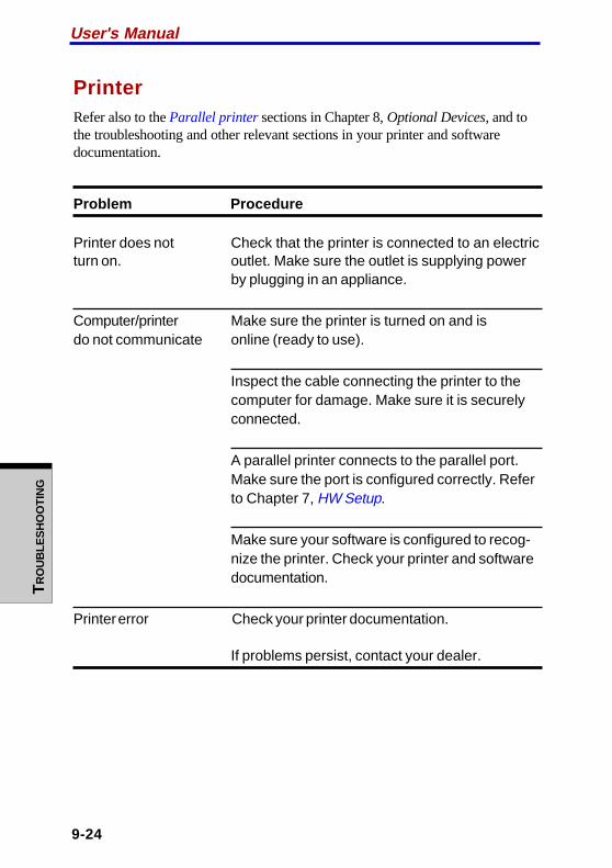
User's ManualT
RO
UB
LES
HO
OT
ING
9-24
PrinterRefer also to the Parallel printer sections in Chapter 8, Optional Devices, and tothe troubleshooting and other relevant sections in your printer and softwaredocumentation.
Problem Procedure
Printer does not Check that the printer is connected to an electricturn on. outlet. Make sure the outlet is supplying power
by plugging in an appliance.
Computer/printer Make sure the printer is turned on and isdo not communicate online (ready to use).
Inspect the cable connecting the printer to thecomputer for damage. Make sure it is securelyconnected.
A parallel printer connects to the parallel port.Make sure the port is configured correctly. Referto Chapter 7, HW Setup.
Make sure your software is configured to recog-nize the printer. Check your printer and softwaredocumentation.
Printer error Check your printer documentation.
If problems persist, contact your dealer.
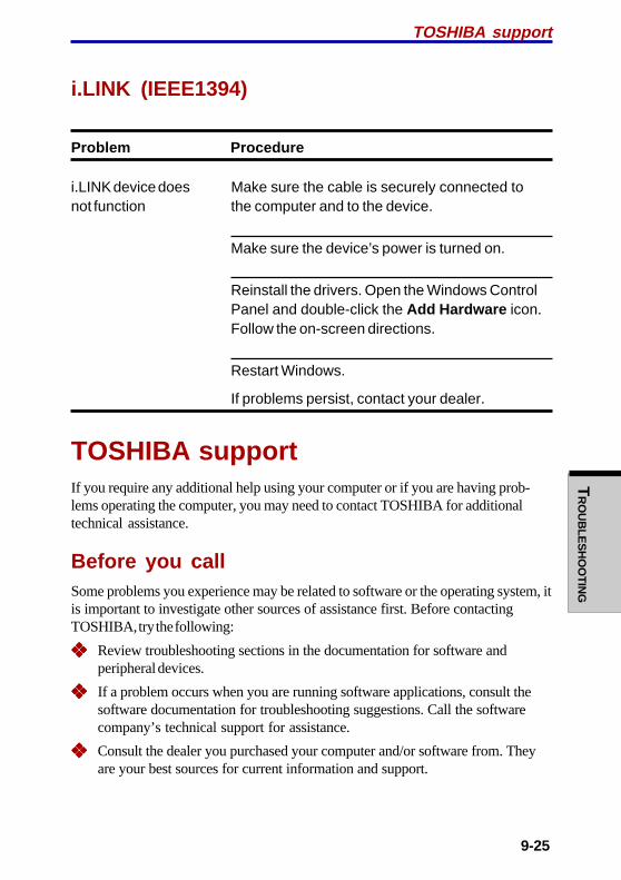
9-25
TR
OU
BLE
SH
OO
TIN
G
i.LINK (IEEE1394)
Problem Procedure
i.LINK device does Make sure the cable is securely connected tonot function the computer and to the device.
Make sure the device’s power is turned on.
Reinstall the drivers. Open the Windows ControlPanel and double-click the Add Hardware icon.Follow the on-screen directions.
Restart Windows.
If problems persist, contact your dealer.
TOSHIBA supportIf you require any additional help using your computer or if you are having prob-lems operating the computer, you may need to contact TOSHIBA for additionaltechnical assistance.
Before you callSome problems you experience may be related to software or the operating system, itis important to investigate other sources of assistance first. Before contactingTOSHIBA, try the following:
❖❖❖❖❖ Review troubleshooting sections in the documentation for software andperipheral devices.
❖❖❖❖❖ If a problem occurs when you are running software applications, consult thesoftware documentation for troubleshooting suggestions. Call the softwarecompany’s technical support for assistance.
❖❖❖❖❖ Consult the dealer you purchased your computer and/or software from. Theyare your best sources for current information and support.
TOSHIBA support
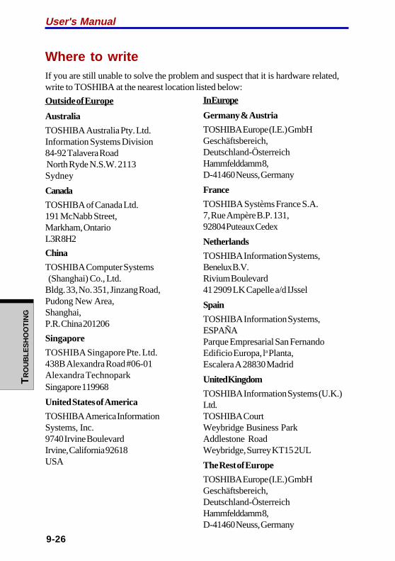
User's ManualT
RO
UB
LES
HO
OT
ING
9-26
Where to writeIf you are still unable to solve the problem and suspect that it is hardware related,write to TOSHIBA at the nearest location listed below:
Outside of Europe
Australia
TOSHIBA Australia Pty. Ltd.Information Systems Division84-92 Talavera Road North Ryde N.S.W. 2113Sydney
Canada
TOSHIBA of Canada Ltd.191 McNabb Street,Markham, OntarioL3R 8H2
China
TOSHIBA Computer Systems (Shanghai) Co., Ltd.Bldg. 33, No. 351, Jinzang Road,Pudong New Area,Shanghai,P.R. China 201206
Singapore
TOSHIBA Singapore Pte. Ltd.438B Alexandra Road #06-01Alexandra TechnoparkSingapore 119968
United States of America
TOSHIBA America InformationSystems, Inc.9740 Irvine BoulevardIrvine, California 92618USA
In Europe
Germany & Austria
TOSHIBA Europe (I.E.) GmbHGeschäftsbereich,Deutschland-ÖsterreichHammfelddamm 8,D-41460 Neuss, Germany
France
TOSHIBA Systèms France S.A.7, Rue Ampère B.P. 131,92804 Puteaux Cedex
Netherlands
TOSHIBA Information Systems,Benelux B.V.Rivium Boulevard41 2909 LK Capelle a/d IJssel
Spain
TOSHIBA Information Systems,ESPAÑAParque Empresarial San FernandoEdificio Europa, la Planta,Escalera A 28830 Madrid
United Kingdom
TOSHIBA Information Systems (U.K.)Ltd.TOSHIBA CourtWeybridge Business ParkAddlestone RoadWeybridge, Surrey KT15 2UL
The Rest of Europe
TOSHIBA Europe (I.E.) GmbHGeschäftsbereich,Deutschland-ÖsterreichHammfelddamm 8,D-41460 Neuss, Germany

AP
PE
ND
IX A
A-1
Appendix A
SpecificationsThis appendix summarizes the computer’s technical specifications.
Physical Dimensions
Weight 2.81 kilograms
Size 360 (w) x 270 (d) x 25.4/35.9 (h) millimeters (notincluding parts that extend beyond the main body)
Environmental Requirements
Ambient RelativeConditions temperature humidity
Operating 5°C (41°F) to 35°C (95°F) 20% to 80%
Non-operating -20°C (-4°F) to 65°C (149°F) 10% to 95%
Thermal Gradient 20°C per hour maximum
Wet-bulb temperature 26°C maximum
Conditions Altitude (from sea level)
Operating -60 to 3,000 meters
Non-operating -60 to 10,000 meters maximum
Power Requirements
Universal AC adaptor 100-240 volts AC
50 or 60 hertz (cycles per second)
Computer 15 VDC5.0 amperes

AP
PE
ND
IX A
A-2
User's Manual
Built-in Modem
Network control unit (NCU)
Type of NCU AA
Type of line Telephone line (analog only)
Type of dialing PulseTone
Control command AT commandsEIA-578 commands
Monitor function Computer’s speaker
Communication specifications
Communication Data: Full duplex system Fax: Half duplex
Communication Data protocol ITU-T-Rec V.21/V.22/V.22bis/V.32
(Former CCITT) /V.32bis/V.34/V.90Bell 103/212A
FaxITU-T-Rec V.17/V.29/V.27ter(Former CCITT) /V.21 ch2
Communication Data transmission and reception speed 300/1200/2400/4800/7200/9600/12000/14400/
16800/19200/21600/24000/26400/28800/31200/33600 bps
Data reception only with V.9028000/29333/30666/32000/33333/34666/36000/37333/38666/40000/41333/42666/44000/45333/46666/48000/49333/50666/52000/53333/54666/56000 bps
Fax2400/4800/7200/9600/12000/14400 bps
Transmitting level -10 dBm
Receiving level -10 to -40 dBm
Input/output 600 ohms ±30% impedance
Error correcting MNP class 4 and ITU-T V.42
Data compression MNP class 5 and ITU-T V.42bis
Power supply +3.3V (supplied by computer)
B-1
AP
PE
ND
IX B
Appendix B
Display Controller andModes
Display controllerThe display controller interprets software commands into hardware commands thatturn particular pels on or off.
The controller is an advanced Video Graphics Array (VGA) that provides WideExtended Graphics Array (WXGA) support for the internal LCD and externalmonitors.
The WXGA screen consists of 1280 x 800 pixels.
A high-resolution external monitor connected to the computer can display up to2048 horizontal and 1536 vertical pixels at 16 M colors.
The display controller also controls the video mode, which uses industry standardrules to govern the screen resolution and the maximum number of colors that can bedisplayed on screen.
Software written for a given video mode will run on any computer that supports themode.
The computer’s display controller supports all VGA and SVGA modes, the mostwidely used industry standards.

User's Manual
B-2
AP
PE
ND
IX B
Video modesThe computer supports video modes defined in the tables below. If your applicationoffers a selection of mode numbers that do not match the numbers on the table,select a mode based on mode type, resolution, character matrix, number of colorsand refresh rates. Also, if your software supports both graphics and text modes, thescreen display may appear to operate faster using a text mode.
Table1 Video modes (VGA)
Video Type Resolution Character LCD CRT Scanningmode matrix colors colors frequency
(pels) Vertical (Hz)
0, 1 VGA 40 x 25 8 x 8 16 of 256K 16 of 256K 70Text Characters
2, 3 VGA 80 x 25 8 x 8 16 of 256K 16 of 256K 70Text Characters
0*, 1* VGA 40 x 25 8 x 14 16 of 256K 16 of 256K 70Text Characters
2*, 3* VGA 80 x 25 8 x 14 16 of 256K 16 of 256K 70Text Characters
0+, 1+ VGA 40 x 25 9 x 16 16 of 256K 16 of 256K 70Text Characters
2+, 3+ VGA 80 x 25 9 x 16 16 of 256K 16 of 256K 70Text Characters
4, 5 VGA 320 x 200 8 x 8 4 of 256K 4 of 256K 70Grph Pels
6 VGA 640 x 200 8 x 8 2 of 256K 2 of 256K 70Grph Pels
7 VGA 80 x 25 9 x 14 Mono Mono 70Text Characters
7+ VGA 80 x 25 9 x 16 Mono Mono 70Text Characters

B-3
AP
PE
ND
IX BAppendix B
Table1 Video modes (VGA) continued
Video Type Resolution Character LCD CRT Scanningmode matrix colors colors frequency
(pels) Vertical (Hz)
D VGA 320 x 200 8 x 8 16 of 256K 16 of 256K 70Grph Pels
E VGA 640 x 200 8 x 8 16 of 256K 16 of 256K 70Grph Pels
F VGA 640 x 350 8 x 14 Mono Mono 70Grph Pels
10 VGA 640 x 350 8 x 14 16 of 256K 16 of 256K 70Grph Pels
11 VGA 640 x 480 8 x 16 2 of 256K 2 of 256K 60Grph Pels
12 VGA 640 x 480 8 x 16 16 of 256K 16 of 256K 60Grph Pels
13 VGA 320 x 200 8 x 8 256 of 256K256 of 256K 70Grph Pels

User's Manual
B-4
AP
PE
ND
IX B
Table 2 Video modes (WXGA)
Resolution LCD CRT Verticalcolors colors frequency (Hz)
640 x 480 256/256K 256/256K 607585
100
800 x 600 256/256K 256/256K 607585
100
1024 x 768 256/256K 256/256K 607585
100
1280 x 800 256/256K 256/256K 607585
100
1280 x 1024 256/256K 256/256K 60(Virtual) 75
85100
1600 x 1200 256/256K 256/256K 60(Virtual) 75
85100
1920 x 1440 256/256K 256/256K 60(Virtual) 75
85
2048 x 1536 256/256K 256/256K 60(Virtual) 75
NOTE: Some video modes do not support multimonitor display.
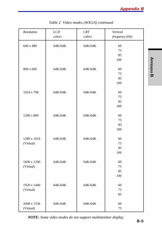
B-5
AP
PE
ND
IX BAppendix B
Table 2 Video modes (WXGA) continued
Resolution LCD CRT Verticalcolors colors frequency (Hz)
640 x 480 64K/64K 64K/64K 607585
100
800 x 600 64K/64K 64K/64K 607585
100
1024 x 768 64K/64K 64K/64K 607585
100
1280 x 800 64K/64K 64K/64K 607585
100
1280 x 1024 64K/64K 64K/64K 60(Virtual) 75
85100
1600 x 1200 64K/64K 64K/64K 60(Virtual) 75
85100
1920 x 1440 64K/64K 64K/64K 60(Virtual) 75
85
2048 x 1536 64K/64K 64K/64K 60(Virtual) 75
NOTE: Some video modes do not support multimonitor display.
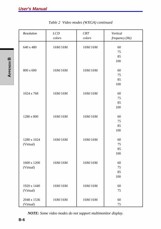
User's Manual
B-6
AP
PE
ND
IX B
Table 2 Video modes (WXGA) continued
Resolution LCD CRT Verticalcolors colors frequency (Hz)
640 x 480 16M/16M 16M/16M 607585
100
800 x 600 16M/16M 16M/16M 607585
100
1024 x 768 16M/16M 16M/16M 607585
100
1280 x 800 16M/16M 16M/16M 607585
100
1280 x 1024 16M/16M 16M/16M 60(Virtual) 75
85100
1600 x 1200 16M/16M 16M/16M 60(Virtual) 75
85100
1920 x 1440 16M/16M 16M/16M 60(Virtual) 75
2048 x 1536 16M/16M 16M/16M 60(Virtual) 75
NOTE: Some video modes do not support multimonitor display.
C-1
AP
PE
ND
IX C
Appendix C
AT CommandsIn most cases, you will not need to type AT commands manually. However, theremight be some occasions when you will need to do so.
This chapter describes AT commands for data mode. Fax and voice commandsare taken care of by application software.
The format for entering AT commands is:
ATXn
where X is the AT command, and n is the specific value for that command. Afteryou type in the command press Enter .
Any command issued is acknowledged with a response in either text or numericvalues known as result codes.
All commands and command-values accepted by the modem are described in thissection; any entry other than those listed results in an error.
+++ Escape sequence
The escape sequence allows the modem to exit data mode and enteronline command mode. While in online command mode, you cancommunicate directly to your modem using AT commands. Once youfinish, you can return to data mode using the ATO command.
A pause, the length of which is set by Escape Guard Time (S12), mustbe completed after an escape sequence is entered, This pause preventsthe modem from interpreting the escape sequence as data.
The value of the escape sequence character may be changed usingregister S2.
A/ Repeat last command
This command repeats the last command string entered. Do not precedethis command with an AT prefix or conclude it by pressing Enter .

User's Manual
C-2
AP
PE
ND
IX C
A Answer command
This command instructs the modem to go off-hook and answer anincoming call.
Bn Communication standard setting
This command determines the communication standard CCITT or Bell.
B0 Selects CCITT V.22 mode when the modem is at 1200 bps.
B1 Selects Bell 212A when the modem is at 1200 bps (default).
B15 Selects V.21 when the modem is at 300 bps.
B16 Selects Bell 103J when the modem is at 300 bps (default).
Result Codes:
OK n=0,1,15,16
ERROROtherwise
Dn Dial
This command instructs the modem to dial a telephone number. Enter n(the telephone number and any modifiers) after the ATD command.
Any digit or symbol (0-9, *, #, A, B, C, D) may be dialed as touch-tonedigits. Characters such as spaces, hyphens, and parentheses do notcount. They are ignored by the modem, but you may want to includethem to make the number and modifiers easier to read.
The following may be used as phone number modifiers:
P Pulse dialing.
T Touch-tone dialing (default).
, Pause during dialing. Pause for time specified in Register S8before processing the next character in the dial string.
W Wait for dial tone. Modem waits for a second dial tone beforeprocessing the dial string.
@ Wait for quiet answer. Wait for five seconds of silence afterdialing the number. If silence is not detected, the modem sendsa NO ANSWER result code back to the caller.
! Hook flash. Causes the modem to go on-hook for 0.5 secondsand then return to off-hook.
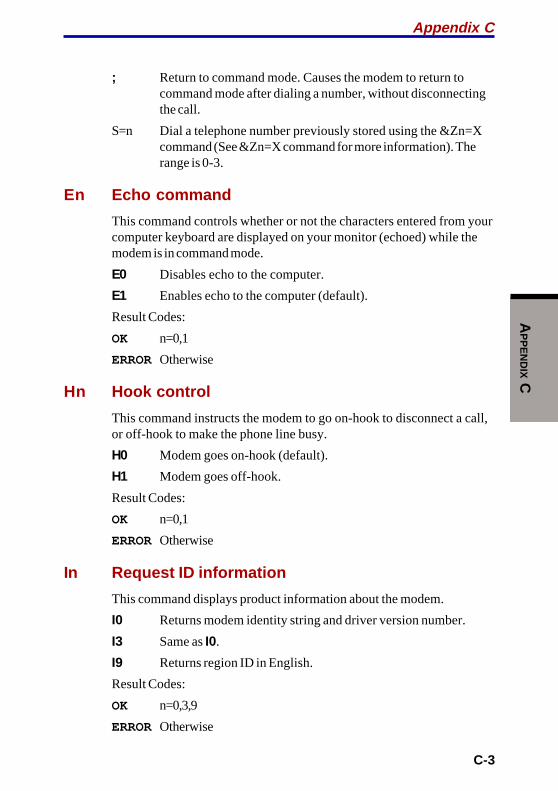
C-3
AP
PE
ND
IX C
; Return to command mode. Causes the modem to return tocommand mode after dialing a number, without disconnectingthe call.
S=n Dial a telephone number previously stored using the &Zn=Xcommand (See &Zn=X command for more information). Therange is 0-3.
En Echo command
This command controls whether or not the characters entered from yourcomputer keyboard are displayed on your monitor (echoed) while themodem is in command mode.
E0 Disables echo to the computer.
E1 Enables echo to the computer (default).
Result Codes:
OK n=0,1
ERROROtherwise
Hn Hook control
This command instructs the modem to go on-hook to disconnect a call,or off-hook to make the phone line busy.
H0 Modem goes on-hook (default).
H1 Modem goes off-hook.
Result Codes:
OK n=0,1
ERROROtherwise
In Request ID information
This command displays product information about the modem.
I0 Returns modem identity string and driver version number.
I3 Same as I0.
I9 Returns region ID in English.
Result Codes:
OK n=0,3,9
ERROROtherwise
Appendix C

User's Manual
C-4
AP
PE
ND
IX C
Ln Monitor speaker volume
This command sets speaker volume to low, medium, or high.
L0 Low volume.
L1 Low volume. (Same as L0)
L2 Medium volume (default).
L3 High volume.
Result Codes:
OK n=0,1,2,3
ERROROtherwise
Mn Monitor speaker mode
This command turns the speaker on or off.
M0 The speaker is off.
M1 The speaker is on until the modem detects the carrier signal(default).
M2 The speaker is always on when modem is off-hook.
M3 Speaker is on until the carrier is detected, except when dialing.
Result Codes:
OK n=0,1,2,3
ERROROtherwise
Nn Modulation handshake
This command controls whether or not the local modem performs anegotiated handshake at connection time with the remote modem whenthe communication speed of the two modems is different.
N0 When originating or answering, this is for handshake only atthe communication standard specified by S37 and the ATBcommand.
N1 When originating or answering, begin the handshake at thecommunication standard specified by S37 and the ATBcommand (default).
During handshake, a lower transmission speed may beselected.

C-5
AP
PE
ND
IX C
Result Codes:
OK n=0,1
ERROROtherwise
On Return online to data mode
O0 Instructs the modem to exit online command mode and returnto data mode (see AT escape sequence, +++).
O1 This command issues a retrain before returning to online datamode.
O3 This command issues a rate renegotiation before returning toonline data mode.
Result Codes:
OK n=0,1,3
ERROROtherwise
P Select pulse dialing
This command configures the modem for pulse (non touch-tone)dialing. Dialed digits are pulsed until a T command or dial modifier isreceived. Tone dial is the default setting.
Qn Result code control
Result codes are informational messages sent from the modem anddisplayed on your monitor. Basic result codes are OK, CONNECT,RING, NO CARRIER, and ERROR. The ATQ command allows the userto turn result codes on or off.
Q0 Enables modem to send result codes to the computer (default).
Q1 Disables modem from sending result codes to the computer.
Result Codes:
OK n=0,1
ERROROtherwise
Appendix C

User's Manual
C-6
AP
PE
ND
IX C
T Select tone dialing
This command instructs the modem to send DTMF tones while dialing.Dialed digits are tone dialed until a P command or dial modifier isreceived. This is the default setting.
Vn DCE response format
This command controls whether result codes (including call progressand negotiation progress messages) are displayed as words or theirnumeric equivalents.
V0 Displays result codes as digits.
V1 Displays result codes as text (default).
Result Codes:
OK n=0,1
ERROROtherwise
Xn Result code selection, call progress monitoring
This command selects which result codes will be used by the modem.
Command Dial tone Busy signal Supported Result
detect detect Code
X0 Disable Disable OK, CONNECT, RING, NO CARRIER,
ERROR
X1 Disable Disable OK, RING, NO CARRIER, ERROR,
CONNECT <RATE>
X2 Enable Disable OK, RING, NO CARRIER, ERROR,
NODIALTONE, CONNECT <RATE>
X3 Disable Enable OK, RING, NO CARRIER, ERROR,
BUSY, CONNECT <RATE>,
BLACKLISTED
X4 (default) Enable Enable OK, RING, NO CARRIER, ERROR,
NODIALTONE, BUSY, CONNECT
<RATE>, DELAYED, BLACKLISTED,
REORDER, WARBLE, CALL WAITING
DETECTED
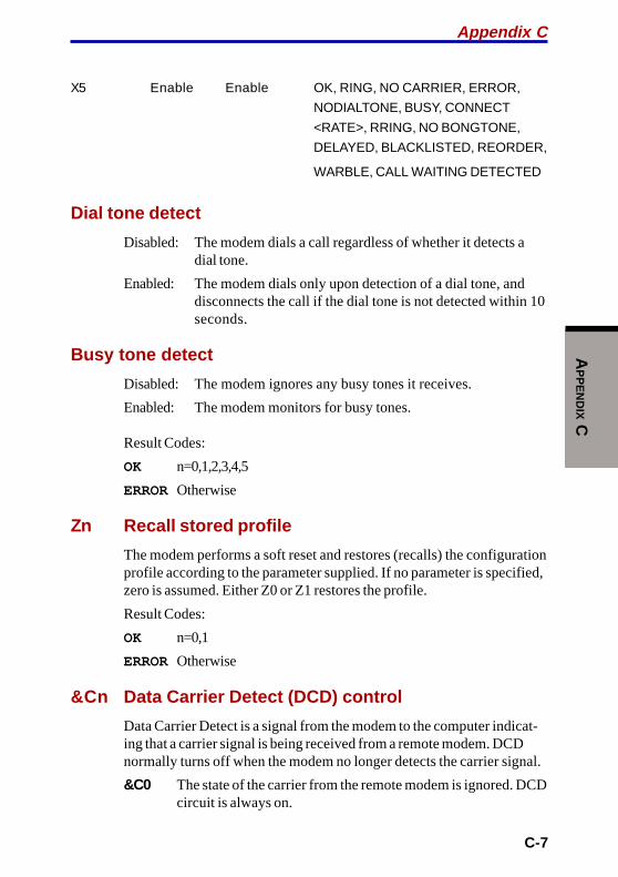
C-7
AP
PE
ND
IX C
X5 Enable Enable OK, RING, NO CARRIER, ERROR,
NODIALTONE, BUSY, CONNECT
<RATE>, RRING, NO BONGTONE,
DELAYED, BLACKLISTED, REORDER,
WARBLE, CALL WAITING DETECTED
Dial tone detect
Disabled: The modem dials a call regardless of whether it detects adial tone.
Enabled: The modem dials only upon detection of a dial tone, anddisconnects the call if the dial tone is not detected within 10seconds.
Busy tone detect
Disabled: The modem ignores any busy tones it receives.
Enabled: The modem monitors for busy tones.
Result Codes:
OK n=0,1,2,3,4,5
ERROROtherwise
Zn Recall stored profile
The modem performs a soft reset and restores (recalls) the configurationprofile according to the parameter supplied. If no parameter is specified,zero is assumed. Either Z0 or Z1 restores the profile.
Result Codes:
OK n=0,1
ERROROtherwise
&Cn Data Carrier Detect (DCD) control
Data Carrier Detect is a signal from the modem to the computer indicat-ing that a carrier signal is being received from a remote modem. DCDnormally turns off when the modem no longer detects the carrier signal.
&C0 The state of the carrier from the remote modem is ignored. DCDcircuit is always on.
Appendix C

User's Manual
C-8
AP
PE
ND
IX C
&C1 DCD turns on when the remote modem’s carrier signal isdetected, and off when the carrier signal is not detected(default).
Result Codes:
OK n=0,1
ERROROtherwise
&Dn DTR control
This command interprets how the modem responds to the state of theDTR signal and changes to the DTR signal.
&D0 Ignore. The modem ignores the true status of DTR and treats itas always on. This should only be used if your communicationsoftware does not provide DTR to the modem
&D1 If the DTR signal is not detected while in online data mode, themodem enters command mode, issues an OK result code, andremains connected.
&D2 If the DTR signal is not detected while in online data mode, themodem disconnects (default).
&D3 Reset on the on-to-off DTR transition.
Result Codes:
OK n=0,1,2,3
ERROROtherwise
&F Load factory settings
This command loads the configuration stored and programmed at thefactory. This operation replaces all of the command options and the S-register settings in the active configuration with factory values.
&F Recall factory setting as active configuration.

C-9
AP
PE
ND
IX C
&Gn V.22bis guard tone control
This command determines which guard tone, if any, to transmit whiletransmitting in the high band (answer mode). This command is onlyused in V.22 and V.22bis mode. This option is not used in NorthAmerica and is for international use only.
&G0 Guard tone disabled (default).
&G1 Sets guard tone to 550 Hz.
&G2 Sets guard tone to 1800 Hz.
Result Codes:
OK n=0,1,2
ERROROtherwise
&Kn Local flow control selection
&K0 Disable flow control.
&K3 Enable CTS/RTS flow control (default).
&K4 Enable XON/XOFF flow control.
Result Codes:
OK n=0,3,4
ERROROtherwise
&Pn Select Pulse Dial Make/Break Ratio (WW)
&P0 Selects 39% - 61% make/break ratio at 10 pulses per second.
&P1 Selects 33% - 67% make/break ratio at 10 pulses per second.
&P2 Selects 33% - 67% make/break ratio at 20 pulses per second.
Result Codes:
OK n=0,1,2
ERROROtherwise
&Tn Self-test commands
These tests can help to isolate problems if you experience periodic dataloss or random errors.
Appendix C
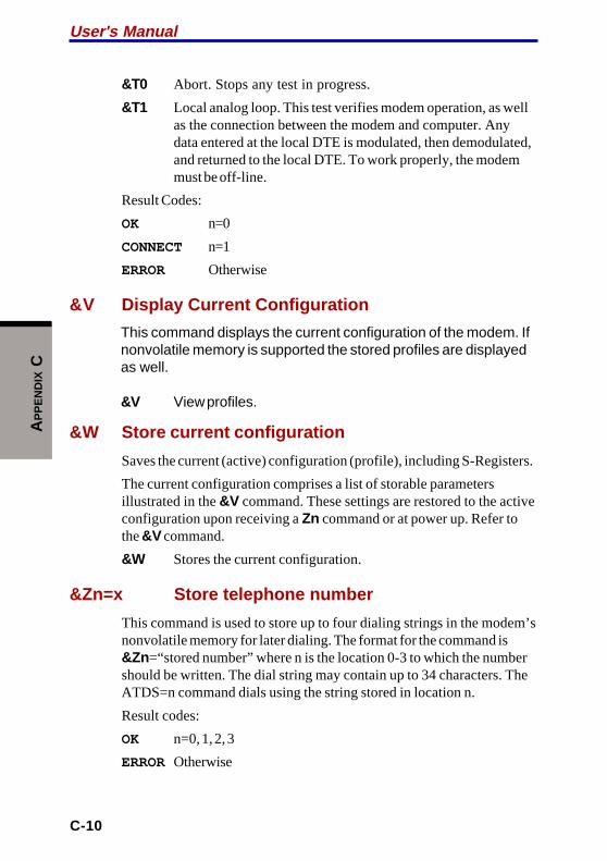
User's Manual
C-10
AP
PE
ND
IX C
&T0 Abort. Stops any test in progress.
&T1 Local analog loop. This test verifies modem operation, as wellas the connection between the modem and computer. Anydata entered at the local DTE is modulated, then demodulated,and returned to the local DTE. To work properly, the modemmust be off-line.
Result Codes:
OK n=0
CONNECT n=1
ERROR Otherwise
&V Display Current Configuration
This command displays the current configuration of the modem. Ifnonvolatile memory is supported the stored profiles are displayedas well.
&V View profiles.
&W Store current configuration
Saves the current (active) configuration (profile), including S-Registers.
The current configuration comprises a list of storable parametersillustrated in the &V command. These settings are restored to the activeconfiguration upon receiving a Zn command or at power up. Refer tothe &V command.
&W Stores the current configuration.
&Zn=x Store telephone number
This command is used to store up to four dialing strings in the modem’snonvolatile memory for later dialing. The format for the command is&Zn=“stored number” where n is the location 0-3 to which the numbershould be written. The dial string may contain up to 34 characters. TheATDS=n command dials using the string stored in location n.
Result codes:
OK n=0, 1, 2, 3
ERROROtherwise
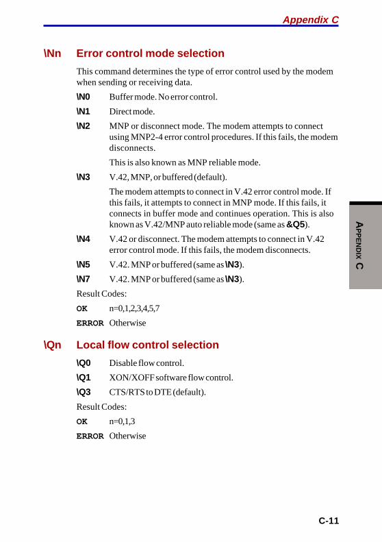
C-11
AP
PE
ND
IX C
\Nn Error control mode selection
This command determines the type of error control used by the modemwhen sending or receiving data.
\N0 Buffer mode. No error control.
\N1 Direct mode.
\N2 MNP or disconnect mode. The modem attempts to connectusing MNP2-4 error control procedures. If this fails, the modemdisconnects.
This is also known as MNP reliable mode.
\N3 V.42, MNP, or buffered (default).
The modem attempts to connect in V.42 error control mode. Ifthis fails, it attempts to connect in MNP mode. If this fails, itconnects in buffer mode and continues operation. This is alsoknown as V.42/MNP auto reliable mode (same as &Q5).
\N4 V.42 or disconnect. The modem attempts to connect in V.42error control mode. If this fails, the modem disconnects.
\N5 V.42. MNP or buffered (same as \N3).
\N7 V.42. MNP or buffered (same as \N3).
Result Codes:
OK n=0,1,2,3,4,5,7
ERROROtherwise
\Qn Local flow control selection
\Q0 Disable flow control.
\Q1 XON/XOFF software flow control.
\Q3 CTS/RTS to DTE (default).
Result Codes:
OK n=0,1,3
ERROROtherwise
Appendix C

User's Manual
C-12
AP
PE
ND
IX C
\Vn Protocol result code
\V0 Disable protocol result code appended to DCE speed.
\V1 Enable protocol result code appended to DCE speed (default).
Result Codes:
OK n=0,1
ERROROtherwise
% B View numbers in blacklist
If blacklisting is in effect, this command displays the numbers for whichthe last call attempted in the past two hours failed. The ERROR resultcode appears in regions that do not require blacklisting.
%Cn Data compression control
This command determines the operation of V.42bis and MNP class 5data compression. Online changes do not take effect until a disconnectoccurs first.
%C0 V.42bis/MNP 5 disabled. No data compression.
%C3 V.42bis/MNP 5 enabled. Data compression enabled (default).
Result Codes:
OK n=0,3
ERROROtherwise

D-1
AP
PE
ND
IX D
Appendix D
S-registersS-registers contain the settings that determine how a number of functions of theinternal modem operate. For example, how many times to let the telephone ringbefore the modem answers and how long to wait before it hangs up if a connec-tion fails. You can also customize certain AT commands such as the escapesequence and command line termination.
The contents of the registers are changed automatically when you modifycorresponding settings in your communication software. If you choose, how-ever, you can display and edit the contents of the registers manually when themodem is in command mode. If the value is out of the acceptable range, then anerror is generated.
This chapter describes the settings for each S-register.
S-register valuesThe format for displaying the value of an S-register is:
ATSn?
where n is the register number. After you type in the register press Enter .
The format for modifying the value of an S-register is:
ATSn=r
where n is the register number, and r is the new register value. After you type inthe register and its new value press Enter .
NOTE: Some registers vary from one country/region to another.
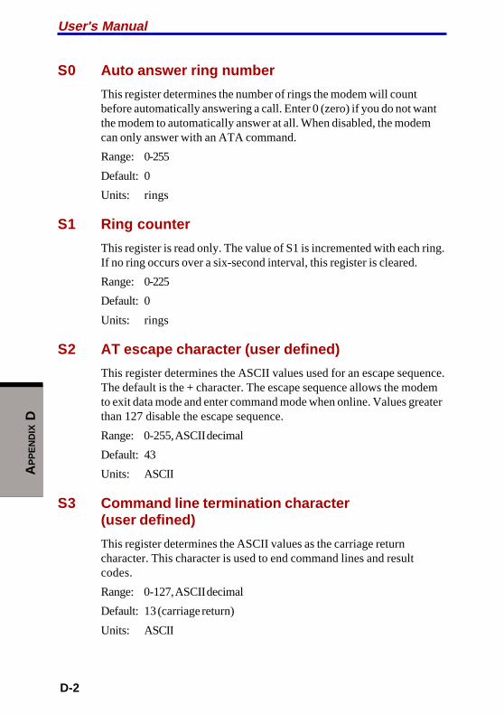
User's Manual
D-2
AP
PE
ND
IX D
S0 Auto answer ring number
This register determines the number of rings the modem will countbefore automatically answering a call. Enter 0 (zero) if you do not wantthe modem to automatically answer at all. When disabled, the modemcan only answer with an ATA command.
Range: 0-255
Default: 0
Units: rings
S1 Ring counter
This register is read only. The value of S1 is incremented with each ring.If no ring occurs over a six-second interval, this register is cleared.
Range: 0-225
Default: 0
Units: rings
S2 AT escape character (user defined)
This register determines the ASCII values used for an escape sequence.The default is the + character. The escape sequence allows the modemto exit data mode and enter command mode when online. Values greaterthan 127 disable the escape sequence.
Range: 0-255, ASCII decimal
Default: 43
Units: ASCII
S3 Command line termination character(user defined)
This register determines the ASCII values as the carriage returncharacter. This character is used to end command lines and resultcodes.
Range: 0-127, ASCII decimal
Default: 13 (carriage return)
Units: ASCII
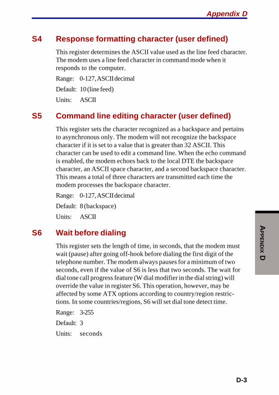
D-3
AP
PE
ND
IX D
S4 Response formatting character (user defined)
This register determines the ASCII value used as the line feed character.The modem uses a line feed character in command mode when itresponds to the computer.
Range: 0-127, ASCII decimal
Default: 10 (line feed)
Units: ASCII
S5 Command line editing character (user defined)
This register sets the character recognized as a backspace and pertainsto asynchronous only. The modem will not recognize the backspacecharacter if it is set to a value that is greater than 32 ASCII. Thischaracter can be used to edit a command line. When the echo commandis enabled, the modem echoes back to the local DTE the backspacecharacter, an ASCII space character, and a second backspace character.This means a total of three characters are transmitted each time themodem processes the backspace character.
Range: 0-127, ASCII decimal
Default: 8 (backspace)
Units: ASCII
S6 Wait before dialing
This register sets the length of time, in seconds, that the modem mustwait (pause) after going off-hook before dialing the first digit of thetelephone number. The modem always pauses for a minimum of twoseconds, even if the value of S6 is less that two seconds. The wait fordial tone call progress feature (W dial modifier in the dial string) willoverride the value in register S6. This operation, however, may beaffected by some ATX options according to country/region restric-tions. In some countries/regions, S6 will set dial tone detect time.
Range: 3-255
Default: 3
Units: seconds
Appendix D

User's Manual
D-4
AP
PE
ND
IX D
S7 Connection completion time-out
This register sets the time, in seconds, that the modem must wait beforehanging up because carrier is not detected. The timer is started whenthe modem finishes dialing (originate), or goes off-hook (answer). Inoriginate mode, the timer is reset upon detection of an answer tone ifallowed by county restriction. The timer also specifies the wait forsilence time for the @ dial modifier in seconds. S7 is not associated withthe W dial modifier.
Range: 1-255
Default: 50
Units: seconds
S8 Comma pause time
This register sets the time, in seconds, that the modem must pausewhen it encounters a comma (,) in the dial command string. In somecountries/regions, S8 will set both wait before dialing and comma pausetime.
Range: 0-255
Default: 2
Units: seconds
S11 DTMF dialing speed
This register determines the dialing speed which is prefixed for eachcountry/region.
Range: 50-255
Default: 95
Units: .001 seconds
S12 Escape guard time
This register sets the value (in 20 millisecond increments) for therequired pause after the escape sequence.
Range: 0-255
Default: 50
Units: .02 seconds
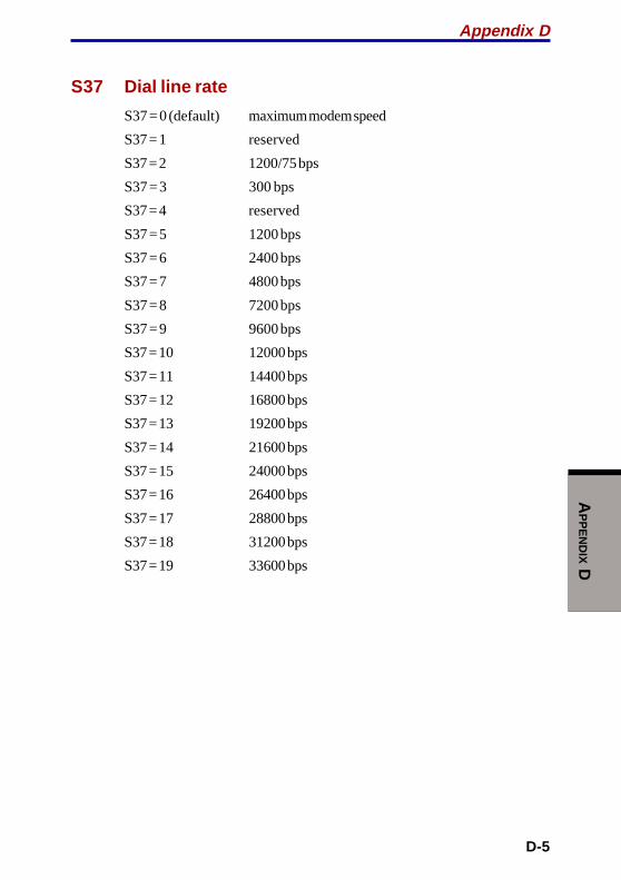
D-5
AP
PE
ND
IX D
S37 Dial line rate
S37 = 0 (default) maximum modem speed
S37 = 1 reserved
S37 = 2 1200/75 bps
S37 = 3 300 bps
S37 = 4 reserved
S37 = 5 1200 bps
S37 = 6 2400 bps
S37 = 7 4800 bps
S37 = 8 7200 bps
S37 = 9 9600 bps
S37 = 10 12000 bps
S37 = 11 14400 bps
S37 = 12 16800 bps
S37 = 13 19200 bps
S37 = 14 21600 bps
S37 = 15 24000 bps
S37 = 16 26400 bps
S37 = 17 28800 bps
S37 = 18 31200 bps
S37 = 19 33600 bps
Appendix D

User's Manual
D-6
AP
PE
ND
IX D
AT command set result codesThe following table shows the result codes.
The result code summary
Result Code Numeric Description
OK 0 Command executed
CONNECT 1 Modem connected to line
RING 2 A ring signal has been detected
NO CARRIER 3 Modem lost carrier signal, or doesnot detect carrier signal, or doesnot detect answer tone
ERROR 4 Invalid command
CONNECT 1200 EC*1 5 Connection at 1200 bps
NO DIAL TONE 6 No dial tone detected
BUSY 7 Busy signal detected
NO ANSWER 8 No quiet answer
CONNECT 2400 EC*1 10 Connection at 2400 bps
CONNECT 4800 EC*1 11 Connection at 4800 bps
CONNECT 9600 EC*1 12 Connection at 9600 bps
CONNECT 14400 EC*1 13 Connection at 14400 bps
CONNECT 19200 EC*1 14 Connection at 19200 bps
CONNECT 7200 EC*1 24 Connection at 7200 bps
CONNECT 12000 EC*1 25 Connection at 12000 bps
CONNECT 16800 EC*1 86 Connection at 16800 bps
CONNECT 300 EC*1 40 Connection at 300 bps
CONNECT 21600 EC*1 55 Connection at 21600 bps
CONNECT 24000 EC*1 56 Connection at 24000 bps
CONNECT 26400 EC*1 57 Connection at 26400 bps
CONNECT 28800 EC*1 58 Connection at 28800 bps
CONNECT 31200 EC*1 59 Connection at 31200 bps
CONNECT 33600 EC*1 60 Connection at 33600 bps
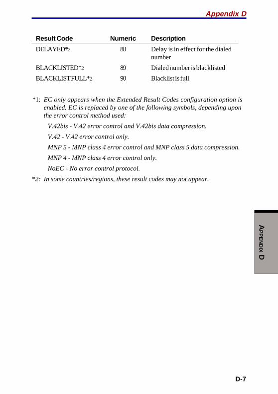
D-7
AP
PE
ND
IX D
Result Code Numeric Description
DELAYED*2 88 Delay is in effect for the dialednumber
BLACKLISTED*2 89 Dialed number is blacklisted
BLACKLIST FULL* 2 90 Blacklist is full
*1: EC only appears when the Extended Result Codes configuration option isenabled. EC is replaced by one of the following symbols, depending uponthe error control method used:
V.42bis - V.42 error control and V.42bis data compression.
V.42 - V.42 error control only.
MNP 5 - MNP class 4 error control and MNP class 5 data compression.
MNP 4 - MNP class 4 error control only.
NoEC - No error control protocol.
*2: In some countries/regions, these result codes may not appear.
Appendix D

User's Manual
D-8
AP
PE
ND
IX D
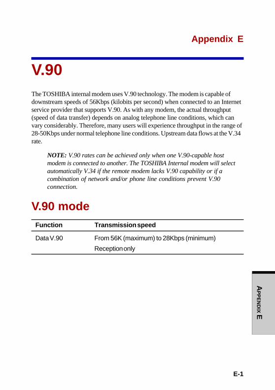
E-1
AP
PE
ND
IX E
Appendix E
V.90The TOSHIBA internal modem uses V.90 technology. The modem is capable ofdownstream speeds of 56Kbps (kilobits per second) when connected to an Internetservice provider that supports V.90. As with any modem, the actual throughput(speed of data transfer) depends on analog telephone line conditions, which canvary considerably. Therefore, many users will experience throughput in the range of28-50Kbps under normal telephone line conditions. Upstream data flows at the V.34rate.
NOTE: V.90 rates can be achieved only when one V.90-capable hostmodem is connected to another. The TOSHIBA Internal modem will selectautomatically V.34 if the remote modem lacks V.90 capability or if acombination of network and/or phone line conditions prevent V.90connection.
V.90 modeFunction Transmission speed
Data V.90 From 56K (maximum) to 28Kbps (minimum)
Reception only

User's Manual
E-2
AP
PE
ND
IX E
Table E-1 Result codes for a V.90 connection
No. Result code Description
70 CONNECT 32000 EC* Connection at 32000 bps
72 CONNECT 36000 EC* Connection at 36000 bps
74 CONNECT 40000 EC* Connection at 40000 bps
76 CONNECT 44000 EC* Connection at 44000 bps
78 CONNECT 48000 EC* Connection at 48000 bps
80 CONNECT 52000 EC* Connection at 52000 bps
82 CONNECT 56000 EC* Connection at 56000 bps
100 CONNECT 28000 EC* Connection at 28000 bps
101 CONNECT 29333 EC* Connection at 29333 bps
102 CONNECT 30666 EC* Connection at 30666 bps
103 CONNECT 33333 EC* Connection at 33333 bps
104 CONNECT 34666 EC* Connection at 34666 bps
105 CONNECT 37333 EC* Connection at 37333 bps
106 CONNECT 38666 EC* Connection at 38666 bps
107 CONNECT 41333 EC* Connection at 41333 bps
108 CONNECT 42666 EC* Connection at 42666 bps
109 CONNECT 45333 EC* Connection at 45333 bps
110 CONNECT 46666 EC* Connection at 46666 bps
111 CONNECT 49333 EC* Connection at 49333 bps
112 CONNECT 50666 EC* Connection at 50666 bps
113 CONNECT 53333 EC* Connection at 53333 bps
114 CONNECT 54666 EC* Connection at 54666 bps

E-3
AP
PE
ND
IX E
*EC stands for the Error Control method, which appears only when the extendedresult codes configuration option is enabled. EC is replaced by one of thefollowing symbols, depending on the error control method used.
V42bis V.42 error control and V.42bis data compression
V42 V.42 error control only
NoEC No error control protocol
AT Command-V90=* V.90 Dial Line Rate
-V90 sets the maximum V.90 downstream that the modem attempts toconnect.
-V90=0 V.90 disabled
-V90=1 V.90 enabled: automatic speed selection - maximum modem speed(default)
Appendix E

User's Manual
E-4
AP
PE
ND
IX E

F-1
AP
PE
ND
IX F
Appendix F
Internal Modem GuideThis appendix describes how to install and the remove the internal modem.
CAUTION: Do not disassemble the computer beyond the steps describedin this instruction or touch any components not specifically described.
Installing the internal modem
NOTE: The internal modem is preinstalled. The following is for informa-tion only.
To install the modem board and jack, follow the steps below.
1. Save your data and turn off the computer.
2. Disconnect the AC adaptor and other peripheral devices.
3. Turn the computer upside down and remove the battery pack.
4. Remove one screw securing the memory module cover.
5. Pull the guide (plastic tab) toward the direction shown by arrow, then lift theHDD. Be careful not to damage the connector.
6. Remove two screws, which you use later to secure the modem board.
7. Connect the modem board cable and seat the modem board.
8. Secure the modem board with two screws removed in step 6.
9. Secure the cover with one screw.
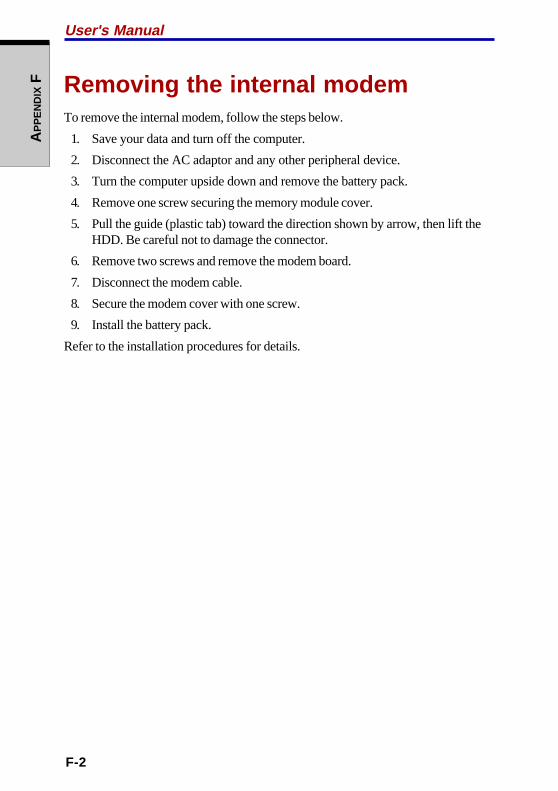
F-2
User's ManualA
PP
EN
DIX
F Removing the internal modemTo remove the internal modem, follow the steps below.
1. Save your data and turn off the computer.
2. Disconnect the AC adaptor and any other peripheral device.
3. Turn the computer upside down and remove the battery pack.
4. Remove one screw securing the memory module cover.
5. Pull the guide (plastic tab) toward the direction shown by arrow, then lift theHDD. Be careful not to damage the connector.
6. Remove two screws and remove the modem board.
7. Disconnect the modem cable.
8. Secure the modem cover with one screw.
9. Install the battery pack.
Refer to the installation procedures for details.
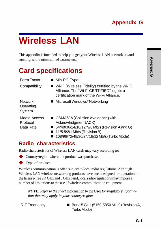
G-1
AP
PE
ND
IX G
Appendix G
Wireless LANThis appendix is intended to help you get your Wireless LAN network up andrunning, with a minimum of parameters.
Card specificationsForm Factor n Mini PCI TypeIII
Compatibility n Wi-Fi (Wireless Fidelity) certified by the Wi-FiAlliance. The “Wi-Fi CERTIFIED” logo is acertification mark of the Wi-Fi Alliance.
Network n Microsoft Windows® NetworkingOperatingSystem
Media Access n CSMA/CA (Collision Avoidance) withProtocol Acknowledgment (ACK)Data Rate n 54/48/36/24/18/12/ 9/6 Mb/s (Revision A and G)
n 11/5.5/2/1 Mb/s (Revision B)n 108/96/72/48/36/24/ 18/12 Mb/s (Turbo Mode)
Radio characteristicsRadio characteristics of Wireless LAN cards may vary according to:
❖❖❖❖❖ Country/region where the product was purchased
❖❖❖❖❖ Type of product
Wireless communication is often subject to local radio regulations. AlthoughWireless LAN wireless networking products have been designed for operation inthe license-free 2.4 GHz and 5 GHz band, local radio regulations may impose anumber of limitations to the use of wireless communication equipment.
NOTE: Refer to the sheet Information to the User for regulatory informa-tion that may apply in your country/region.
R-F Frequency n Band 5 GHz (5150-5850 MHz) (Revision A,Turbo Mode)
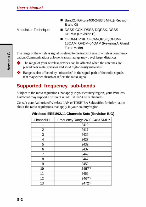
G-2
User's ManualA
PP
EN
DIX
G
n Band 2.4 GHz (2400-2483.5 MHz) (RevisionB and G)
Modulation Technique n DSSS-CCK, DSSS-DQPSK, DSSS-DBPSK (Revision B)
n OFDM-BPSK, OFDM-QPSK, OFDM-16QAM, OFDM-64QAM (Revision A, G andTurbo Mode)
The range of the wireless signal is related to the transmit rate of wireless communi-cation. Communications at lower transmit range may travel larger distances.
❖❖❖❖❖ The range of your wireless devices can be affected when the antennas areplaced near metal surfaces and solid high-density materials.
❖❖❖❖❖ Range is also affected by "obstacles" in the signal path of the radio signalsthat may either absorb or reflect the radio signal.
Supported frequency sub-bandsSubject to the radio regulations that apply in your country/region, your WirelessLAN card may support a different set of 5 GHz/2.4 GHz channels.
Consult your Authorized Wireless LAN or TOSHIBA Sales office for informationabout the radio regulations that apply in your country/region.
Wireless IEEE 802.11 Channels Sets (Revision B/G)
Channel ID Frequency Range 2400-2483.5 MHz1 24122 24173 24224 24275 24326 24377 24428 24479 2452
10 2457 *1
11 246212 2467 *2
13 2472 *2

G-3
AP
PE
ND
IX G
*1 Factory-set default channels
*2 Refer to the sheet Approved Countries/Regions for use for the countries/regionsthat in which these channels can be used.
When installing Wireless LAN Cards, the channel configuration is managed asfollows:
❖❖❖❖❖ For wireless clients that operate in a Wireless LAN Infrastructure, the WirelessLAN Card will automatically start operation at the channel identified by theWireless LAN Access Point, When roaming between different access pointsthe station can dynamically switch to another channel if required.
❖❖❖❖❖ For Wireless LAN Cards installed in Wireless clients that operating in a peer-to-peer mode, the card will use the default channel 10.
❖❖❖❖❖ In a Wireless LAN Access Point, the Wireless LAN card will use the factory-set default channel (printed in bold), unless the LAN Administrator selected adifferent channel when configuring the Wireless LAN Access Point device.
Wireless IEEE 802.11 Channels Sets (Revision A)
Channel ID Frequency Range 5150-5850 MHz Note36 518040 520044 522048 524052 526056 528060 530064 5320
149 5745153 5765157 5785161 5805
Appendix G

G-4
User's ManualA
PP
EN
DIX
G
Wireless Channels Sets (Turbo Mode)
Channel ID Frequency Range 5150-5850 MHz Note42 5210 US only *
50 5250 US only *
58 5290 US only *
152 5760 US only *
160 5800 US only *
*: Available Area: US (USA, CANADA) only

H-1
AP
PE
ND
IX H
Appendix H
AC Power Cord andConnectorsThe power cord’s AC input plug must be compatible with the various internationalAC power outlets and the cord must meet the standards for the country/region inwhich it is used. All cords must meet the following specifications:
Length: Minimum 2 meters
Wire size: Minimum 0.75 mm2
Current rating: Minimum 2.5 amperes
Voltage rating: 125 or 250 VAC(depending on country/region’s power standards)
Certification agencies
U.S. and Canada: UL listed and CSA certified
No. 18 AWG, Type SVT or SPT-2 two conductor
Europe:
Austria: OVE Italy: IMQ
Belgium: CEBEC The Netherlands: KEMA
Denmark: DEMKO Norway: NEMKO
Finland: SETI Sweden: SEMKO
France: UTE Switzerland: SEV
Germany: VDE United Kingdom: BSI
Australia: AS
Japan: DENANHO
In Europe, power cords must be VDE type, H05VVH2-F and two conductor.
For the United States and Canada, plug configuration must be a 2-15P (250 V) or 1-15P (125 V) as designated in the U.S. National Electrical code handbook and theCanadian Electrical Code Part II.

H-2
User's ManualA
PP
EN
DIX
H
The following illustrations show the plug shapes for the U.S.A. and Canada, theUnited Kingdom, Australia and Europe.
USA and Canada United Kingdom
Australia Europe
BS approvedUL approvedCSA approved
AS approved Approved by theappropriate agency

AP
PE
ND
IX I
I-1
Appendix I
Parts NumbersThe computer configuration and parts numbers, printed on a label on the bottom ofthe computer, indicate the CPU, LCD, memory, HDD, ODD, communication andgraphics devices.

APPENDIX IU
ser's Manual
I-2
ConfigurationsThe following table shows the computer configuration indicated on a label. Shaded areas indicate abbreviations used on the label.The explanations are to the left of the shading. Abbreviations are not limited to those in this chart. They may change withoutnotice.
UPCM-muitneP
DCL yromeM DDH DDO noitacinummoC scihparG
zHG04.1 4.1B AGX-TFTW"4.51 XW51 BM652 M652 G04 04 MOR-DVD/WR-DC VD/WR b11.208 bLW )BM23(M43VN V23
zHG05.1 5.1BAGX-TFTW"4.51
)VSC(CXW51 BM652+BM652 M215 G06 06 WR-/R-DVD RVD b/a11.208 baLW )BM46(43PAM V46
zHG06.1 6.1B BM215 M215 G08 08 itluMDVD MRD g11.208 gLW
zHG07.1 7.1B BM652+BM215 M867 g/a11.208 gaLW
BM215+BM215 M4201
M4201 M4201
BM652+M4201 M0821
BM215+M4201 M6351
BM4201+M4201 M8402
User's Manual
AP
PE
ND
IX I
I-2

Glossary-1
GLO
SS
AR
Y
GlossaryThe terms in this glossary cover topics related to this manual. Alternate namingis included for reference.
Abbreviations
AC: alternating current
AGP: accelerated graphics port
ANSI: American National StandardsInstitute
APM: advanced power manager
ASCII: American Standard Code forInformation Interchange
BIOS: basic input output system
CD-ROM: Compact Disc-Read OnlyMemory
CD-RW: Compact Disc-Read/Write
CMOS: complementary metal-oxidesemiconductor
CPU: central processing unit
CRT: cathode ray tube
DC: direct current
DDC: display data channel
DMA: direct memory access
DOS: disk operating system
DVD: digital versatile disc
DVD-R: Digital Versatile Disc Record-able
DVD-RAM: Digital Versatile DiscRandom Access Memory
DVD-ROM: Digital Versatile DiscRead Only Memory
DVD-RW: Digital Versatile Disc Read/Write
ECP: extended capabilities port
FDD: floppy disk drive
FIR: fast infrared
GB: gigabyte
HDD: hard disk drive
IDE: integrated drive electronics
I/O: input/output
IrDA: Infrared Data Association
IRQ: interrupt request
KB: kilobyte
LCD: liquid crystal display
LED: light emitting diode
LSI: large scale integration
MB: megabyte
OCR: optical character recognition(reader)
PCB: printed circuit board
PCI: peripheral component intercon-nect
RAM: random access memory
RGB: red, green, and blue

Glossary-2
GLO
SS
AR
Y alphanumeric: Keyboard charactersincluding letters, numbers and othersymbols, such as punctuation marks ormathematical symbols.
alternating current (AC): Electriccurrent that reverses its direction offlow at regular intervals.
analog signal: A signal whosecharacteristics such as amplitude andfrequency vary in proportion to (are ananalog of) the value to be transmitted.Voice communications are analogsignals.
ANSI: American National StandardsInstitute. An organization establishedto adopt and define standards for avariety of technical disciplines. Forexample, ANSI defined the ASCIIstandard and other informationprocessing requirements.
antistatic: A material used to preventthe buildup of static electricity.
application: A group of programsthat together are used for a specifictask such as accounting, financialplanning, spreadsheets, word process-ing and games.
ASCII: American Standard Code forInformation Interchange. ASCII code isa set of 256 binary codes that representthe most commonly used letters,numbers, and symbols.
async: Short for asynchronous.
(Abbreviations continued)
ROM: read only memory
RTC: real time clock
SCSI: small computer systeminterface
SIO: serial input/output
TFT: thin-film transistor
UART: universal asynchronousreceiver/transmitter
USB: Universal Serial Bus
VESA: Video Electronic StandardsAssociation
VGA: video graphics array
VRT: voltage reduction technology
WXGA: wide extended graphics array
XGA: extended graphics array
A
adaptor: A device that provides aninterface between two dissimilarelectronic devices. For example, theAC adaptor modifies the power from awall outlet for use by the computer.This term also refers to the add-incircuit cards that control externaldevices, such as video monitors andmagnetic tape devices.
allocate: To assign a space orfunction for a specific task.
adaptor

Glossary-3
GLO
SS
AR
Y
asynchronous: Lacking regular timerelationship. As applied to computercommunications, asynchronous refersto the method of transmitting data thatdoes not require a steady stream ofbits to be transmitted at regular timeintervals.
B
backup: A duplicate copy of files keptas a spare in case the original isdestroyed.
batch file: A file that can be executedfrom the system prompt containing asequence of operating system com-mands or executable files.
binary: The base two number systemcomposed of zeros and ones (off oron), used by most digital computers.The right-most digit of a binary numberhas a value of 1, the next a value of 2,then 4, 8, 16, and so on. For example,the binary number 101 has a value of 5.See also ASCII.
BIOS: Basic Input Output System.The firmware that controls data flowwithin the computer. See also firmware.
bit: Derived from "binary digit," thebasic unit of information used by thecomputer. It is either zero or one. Eightbits is one byte. See also byte.
board: A circuit board. An internalcard containing electronic compo-nents, called chips, which perform aspecific function or increase thecapabilities of the system.
boot: Short for bootstrap. A programthat starts or restarts the computer.The program reads instructions from astorage device into the computer’smemory.
bps: Bits per second. Typically usedto describe the data transmissionspeed of a modem.
buffer: The portion of the computer’smemory where data is temporarilystored. Buffers often compensate fordifferences in the rate of flow from onedevice to another.
bus: An interface for transmission ofsignals, data or electric power.
byte: The representation of a singlecharacter. A sequence of eight bitstreated as a single unit; also thesmallest addressable unit within thesystem.
C
cache memory: High speed memorywhich stores data that increasesprocessor speed and data transfer rate.When the CPU reads data from mainmemory, it stores a copy of this data incache memory. The next time the CPUneeds that same data, it looks for it inthe cache memory rather than the mainmemory, which saves time. Thecomputer has two cache levels. Levelone is incorporated into the processorand level two resides in externalmemory.
cache memory
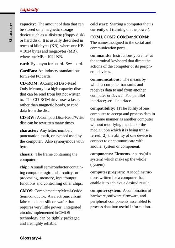
Glossary-4
GLO
SS
AR
Y capacity: The amount of data that canbe stored on a magnetic storagedevice such as a diskette (floppy disk)or hard disk. It is usually described interms of kilobytes (KB), where one KB= 1024 bytes and megabytes (MB),where one MB = 1024 KB.
card: Synonym for board. See board.
CardBus: An industry standard busfor 32-bit PC cards.
CD-ROM: A Compact Disc-ReadOnly Memory is a high capacity discthat can be read from but not writtento. The CD-ROM drive uses a laser,rather than magnetic heads, to readdata from the disc.
CD-RW: A Compact Disc-Read/Writedisc can be rewritten many times.
character: Any letter, number,punctuation mark, or symbol used bythe computer. Also synonymous withbyte.
chassis: The frame containing thecomputer.
chip: A small semiconductor contain-ing computer logic and circuitry forprocessing, memory, input/outputfunctions and controlling other chips.
CMOS: Complementary Metal-OxideSemiconductor. An electronic circuitfabricated on a silicon wafer thatrequires very little power. Integratedcircuits implemented in CMOStechnology can be tightly packagedand are highly reliable.
cold start: Starting a computer that iscurrently off (turning on the power).
COM1, COM2, COM3 and COM4:The names assigned to the serial andcommunication ports.
commands: Instructions you enter atthe terminal keyboard that direct theactions of the computer or its periph-eral devices.
communications: The means bywhich a computer transmits andreceives data to and from anothercomputer or device. See parallelinterface; serial interface.
compatibility: 1) The ability of onecomputer to accept and process data inthe same manner as another computerwithout modifying the data or themedia upon which it is being trans-ferred. 2) the ability of one device toconnect to or communicate withanother system or component.
components: Elements or parts (of asystem) which make up the whole(system).
computer program: A set of instruc-tions written for a computer thatenable it to achieve a desired result.
computer system: A combination ofhardware, software, firmware, andperipheral components assembled toprocess data into useful information.
capacity
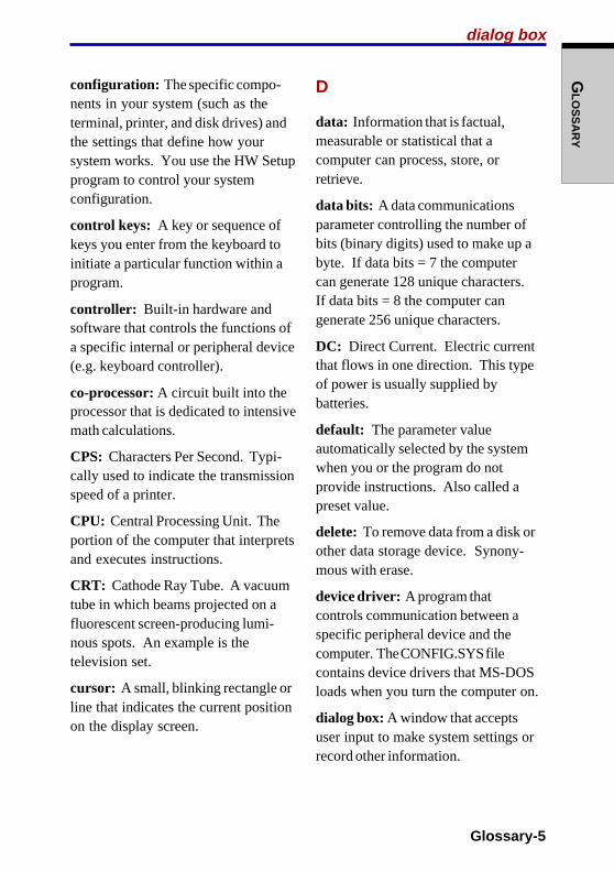
Glossary-5
GLO
SS
AR
Y
configuration: The specific compo-nents in your system (such as theterminal, printer, and disk drives) andthe settings that define how yoursystem works. You use the HW Setupprogram to control your systemconfiguration.
control keys: A key or sequence ofkeys you enter from the keyboard toinitiate a particular function within aprogram.
controller: Built-in hardware andsoftware that controls the functions ofa specific internal or peripheral device(e.g. keyboard controller).
co-processor: A circuit built into theprocessor that is dedicated to intensivemath calculations.
CPS: Characters Per Second. Typi-cally used to indicate the transmissionspeed of a printer.
CPU: Central Processing Unit. Theportion of the computer that interpretsand executes instructions.
CRT: Cathode Ray Tube. A vacuumtube in which beams projected on afluorescent screen-producing lumi-nous spots. An example is thetelevision set.
cursor: A small, blinking rectangle orline that indicates the current positionon the display screen.
D
data: Information that is factual,measurable or statistical that acomputer can process, store, orretrieve.
data bits: A data communicationsparameter controlling the number ofbits (binary digits) used to make up abyte. If data bits = 7 the computercan generate 128 unique characters.If data bits = 8 the computer cangenerate 256 unique characters.
DC: Direct Current. Electric currentthat flows in one direction. This typeof power is usually supplied bybatteries.
default: The parameter valueautomatically selected by the systemwhen you or the program do notprovide instructions. Also called apreset value.
delete: To remove data from a disk orother data storage device. Synony-mous with erase.
device driver: A program thatcontrols communication between aspecific peripheral device and thecomputer. The CONFIG.SYS filecontains device drivers that MS-DOSloads when you turn the computer on.
dialog box: A window that acceptsuser input to make system settings orrecord other information.
dialog box

Glossary-6
GLO
SS
AR
Y disk drive: The device that randomlyaccesses information on a disk andcopies it to the computer’s memory. Italso writes data from memory to thedisk. To accomplish these tasks, theunit physically rotates the disk at highspeed past a read-write head.
disk storage: Storing data on magneticdisk. Data is arranged on concentrictracks much like a phonograph record.
diskette: A removable disk that storesmagnetically encoded data. Alsocalled a floppy disk.
display: A CRT, LCD, or other imageproducing device used to viewcomputer output.
documentation: The set of manualsand/or other instructions written for theusers of a computer system or applica-tion. Computer system documentationtypically includes procedural andtutorial information as well as systemfunctions.
driver: A software program, generallypart of the operating system, thatcontrols a specific piece of hardware(frequently a peripheral device such asa printer or mouse).
DVD-R: A Digital Versatile Disc-Recordable disk can be written onceand read many times.
DVD-RAM: A Digital Versatile DiscRandom Access Memory is a high-capacity, high performance disc thatlets you store large volumes of data.The DVD drive uses a laser to readdata from the disc.
DVD-ROM: A Digital Versatile DiscRead Only Memory is a high capacity,high performance disc suitable forplay back of video and other high-density files. The DVD drive uses alaser to read data from the disc.
DVD-RW: A Compact Disc-Read/Write disc can be rewritten manytimes.
E
echo: To send back a reflection of thetransmitted data to the sendingdevice. You can display the informa-tion on the screen, or output it to theprinter, or both. When a computerreceives back data it transmitted to aCRT (or other peripheral device) andthen retransmits the data to printer,the printer is said to echo the CRT.
erase: See delete.
escape: 1) A code ( ASCII code 27),signaling the computer that whatfollows are commands; used withperipheral devices such as printersand modems. 2) A means of abortingthe task currently in progress.
disk drive
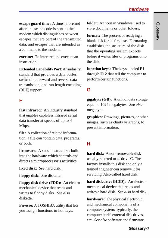
Glossary-7
GLO
SS
AR
Y
escape guard time: A time before andafter an escape code is sent to themodem which distinguishes betweenescapes that are part of the transmitteddata, and escapes that are intended asa command to the modem.
execute: To interpret and execute aninstruction.
Extended Capability Port: An industrystandard that provides a data buffer,switchable forward and reverse datatransmission, and run length encoding(RLE) support.
F
fast infrared: An industry standardthat enables cableless infrared serialdata transfer at speeds of up to 4Mbps.
file: A collection of related informa-tion; a file can contain data, programs,or both.
firmware: A set of instructions builtinto the hardware which controls anddirects a microprocessor’s activities.
fixed disk: See hard disk.
floppy disk: See diskette.
floppy disk drive (FDD): An electro-mechanical device that reads andwrites to floppy disks. See alsodiskette.
Fn-esse: A TOSHIBA utility that letsyou assign functions to hot keys.
folder: An icon in Windows used tostore documents or other folders.
format: The process of readying ablank disk for its first use. Formattingestablishes the structure of the diskthat the operating system expectsbefore it writes files or programs ontothe disk.
function keys: The keys labeled F1through F12 that tell the computer toperform certain functions.
G
gigabyte (GB): A unit of data storageequal to 1024 megabytes. See alsomegabyte.
graphics: Drawings, pictures, or otherimages, such as charts or graphs, topresent information.
H
hard disk: A non-removable diskusually referred to as drive C. Thefactory installs this disk and only atrained engineer can remove it forservicing. Also called fixed disk.
hard disk drive (HDD): An electro-mechanical device that reads andwrites a hard disk. See also hard disk.
hardware: The physical electronicand mechanical components of acomputer system: typically, thecomputer itself, external disk drives,etc. See also software and firmware.
hardware

Glossary-8
GLO
SS
AR
Y hertz: A unit of wave frequency thatequals one cycle per second.
hexadecimal: The base 16 numberingsystem composed of the digits 0through 9 and the letters A, B, C, D, E,and F.
host computer: The computer thatcontrols, regulates, and transmitsinformation to a device or anothercomputer.
hotkey: The computer’s feature inwhich certain keys in combination withthe extended function key, Fn, can beused to set system parameters, suchas speaker volume.
HW Setup: A TOSHIBA utility thatlets you set the parameters for varioushardware components.
I
icon: A small graphic image displayedon the screen or in the indicator panel.In Windows, an icon represents anobject that the user can manipulate.
infrared port: A cableless communi-cations port capable of using infraredsignals to send serial data.
input: The data or instructions youprovide to a computer, communicationdevice or other peripheral device fromthe keyboard or external or internalstorage devices. The data sent (oroutput) by the sending computer isinput for the receiving computer.
instruction: Statements or commandsthat specify how to perform a particu-lar task.
interface: 1) Hardware and/orsoftware components of a systemused specifically to connect onesystem or device to another. 2) Tophysically connect one system ordevice to another to exchangeinformation. 3) The point of contactbetween user, the computer, and theprogram, for example, the keyboard ora menu.
interrupt request: A signal that givesa component access to the processor.
I/O: Input/output. Refers to accep-tance and transfer of data to and froma computer.
I/O devices: Equipment used tocommunicate with the computer andtransfer data to and from it.
IrDA 1.1: An industry standard thatenables cableless infrared serial datatransfer at speeds of up to 4 Mbps.
K
K: Taken from the Greek word kilo,meaning 1000; often used as equiva-lent to 1024, or 2 raised to the 10thpower. See also byte and kilobyte.
KB: See kilobyte.
hertz

Glossary-9
GLO
SS
AR
Y
M
main board: See motherboard.
megabyte (MB): A unit of datastorage equal to 1024 kilobytes. Seealso kilobyte.
megahertz: A unit of wave frequencythat equals 1 million cycles persecond. See also hertz.
menu: A software interface thatdisplays a list of options on thescreen. Also called a screen.
microprocessor: A hardware compo-nent contained in a single integratedcircuit that carries out instructions.Also called the central processing unit(CPU), one of the main parts of thecomputer.
mode: A method of operation, forexample, the boot mode, standbymode or the hibernation mode.
modem: Derived from modulator/demodulator, a device that converts(modulates) digital data for transmis-sion over telephone lines and thenconverts modulated data (demodu-lates) to digital format where received.
monitor: A device that uses rows andcolumns of pixels to display alphanu-meric characters or graphic images.See also CRT.
monitor
keyboard: An input device contain-ing switches that are activated bymanually pressing marked keys. Eachkeystroke activates a switch thattransmits a specific code to thecomputer. For each key, the transmit-ted code is, in turn, representative ofthe (ASCII) character marked on thekey.
kilobyte (KB): A unit of data storageequal to 1024 bytes. See also byteand megabyte.
L
level 2 cache: See cache.
Light Emitting Diode (LED): Asemiconductor device that emits lightwhen a current is applied.
Liquid Crystal Display (LCD): Liquidcrystal sealed between two sheets ofglass coated with transparent con-ducting material. The viewing-sidecoating is etched into characterforming segments with leads thatextend to the edge of the glass.Applying a voltage between the glasssheets alters the brightness of theliquid crystal.
LSI: Large Scale Integration. 1) Atechnology that allows the inclusionof up to 100,000 simple logic gates ona single chip. 2) An integrated circuitthat uses large scale integration.
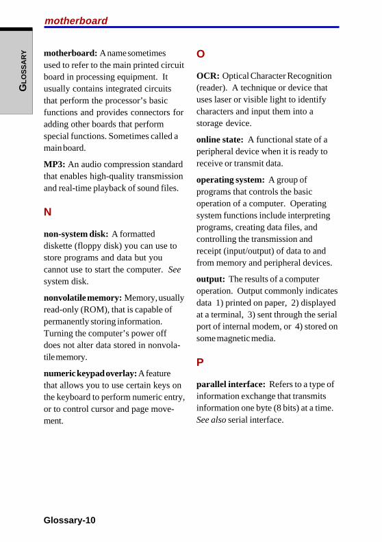
Glossary-10
GLO
SS
AR
Y O
OCR: Optical Character Recognition(reader). A technique or device thatuses laser or visible light to identifycharacters and input them into astorage device.
online state: A functional state of aperipheral device when it is ready toreceive or transmit data.
operating system: A group ofprograms that controls the basicoperation of a computer. Operatingsystem functions include interpretingprograms, creating data files, andcontrolling the transmission andreceipt (input/output) of data to andfrom memory and peripheral devices.
output: The results of a computeroperation. Output commonly indicatesdata 1) printed on paper, 2) displayedat a terminal, 3) sent through the serialport of internal modem, or 4) stored onsome magnetic media.
P
parallel interface: Refers to a type ofinformation exchange that transmitsinformation one byte (8 bits) at a time.See also serial interface.
motherboard
motherboard: A name sometimesused to refer to the main printed circuitboard in processing equipment. Itusually contains integrated circuitsthat perform the processor’s basicfunctions and provides connectors foradding other boards that performspecial functions. Sometimes called amain board.
MP3: An audio compression standardthat enables high-quality transmissionand real-time playback of sound files.
N
non-system disk: A formatteddiskette (floppy disk) you can use tostore programs and data but youcannot use to start the computer. Seesystem disk.
nonvolatile memory: Memory, usuallyread-only (ROM), that is capable ofpermanently storing information.Turning the computer’s power offdoes not alter data stored in nonvola-tile memory.
numeric keypad overlay: A featurethat allows you to use certain keys onthe keyboard to perform numeric entry,or to control cursor and page move-ment.
Glossary-11
GLO
SS
AR
Y
parity: 1) The symmetrical relation-ship between two parameter values(integers) both of which are either onor off; odd or even; 0 or 1. 2) In serialcommunications, an error detection bitthat is added to a group of data bitsmaking the sum of the bits even orodd. Parity can be set to none, odd, oreven.
password: A unique string of charac-ters used to identify a specific user.The computer provides various levelsof password protection such as user,supervisor and eject.
pel: The smallest area of the displaythat can be addressed by software.Equal in size to a pixel or group ofpixels. See pixel.
peripheral component interconnect:An industry standard 32-bit bus.
peripheral device: An I/O device thatis external to the central processorand/or main memory such as a printeror a mouse.
pixel: A picture element. The smallestdot that can be made on a display orprinter. Also called a pel.
plug and play: A capability withWindows that enables the system toautomatically recognize connectionsof external devices and make thenecessary configurations in thecomputer.
port: The electrical connectionthrough which the computer sendsand receives data to and from devicesor other computers.
Power Saver Utility: A TOSHIBAutility that lets you set the parametersfor various power-saving functions.
printed circuit board (PCB): Ahardware component of a processor towhich integrated circuits and othercomponents are attached. The boarditself is typically flat and rectangular,and constructed of fiberglass, to formthe attachment surface.
program: A set of instructions acomputer can execute that enables itto achieve a desired result. See alsoapplication.
prompt: A message the computerprovides indicating it is ready for orrequires information or an action fromyou.
prompt

Glossary-12
GLO
SS
AR
Y ROM: Read Only Memory: Anonvolatile memory chip manufac-tured to contain information thatcontrols the computer’s basicoperation. You cannot access orchange information stored in ROM.
S
SCSI: Small Computer SystemInterface is an industry standardinterface for connection of a variety ofperipheral devices.
SD cards: Secure Digital cards areflash memory widely used in a varietyof digital devices such as digitalcameras and Personal Digital Assis-tants.
SIO: Serial Input/Output. Theelectronic methodology used in serialdata transmission.
soft key: Key combinations thatemulate keys on the IBM keyboard,change some configuration options,stop program execution, and accessthe numeric keypad overlay.
software: The set of programs,procedures and related documentationassociated with a computer system.Specifically refers to computerprograms that direct and control thecomputer system’s activities. Seealso hardware.
stop bit: One or more bits of a bytethat follow the transmitted characteror group codes in asynchronous serialcommunications.
Radio frequency interference (RFI) shield
R
Radio frequency interference (RFI)shield: A metal shield enclosing theprinted circuit boards of the printer orcomputer to prevent radio and TVinterference. All computer equipmentgenerates radio frequency signals.The FCC regulates the amount ofsignals a computing device can allowpast its shielding. A Class A device issufficient for office use. Class Bprovides a more stringent classifica-tion for home equipment use.TOSHIBA portable computers complywith Class B computing deviceregulations.
Random Access Memory (RAM):High speed memory within thecomputer circuitry that can be read orwritten to.
restart: Resetting a computer withoutturning it off (also called “warm boot”or “soft reset”). See also boot.
RGB: Red, green, and blue. A devicethat uses three input signals, eachactivating an electron gun for aprimary additive color (red, green, andblue) or port for using such a device.See also CRT.
RJ11: A modular telephone jack.
RJ45: A modular LAN jack.
Glossary-13
GLO
SS
AR
Y
subpixel: Three elements, one red,one green and blue (RGB), that makeup a pixel on the color LCD. Thecomputer sets subpixels indepen-dently, each may emit a differentdegree of brightness. See also pixel.
synchronous: Having a constant timeinterval between successive bits,characters or events.
system disk: A disk that has beenformatted with an operating system.For MS-DOS the operating system iscontained in two hidden files and theCOMMAND.COM file. You can boot acomputer using a system disk. Alsocalled an operating system disk.
T
terminal: A typewriter-like keyboardand CRT display screen connected tothe computer for data input/output.
TFT: Thin-film transistor, a color LCDtechnology that applies individualtransistors to each pixel enabling finedisplay control and excellent screenlegibility.
Touch Pad: A pointing deviceintegrated into the TOSHIBA com-puter palm rest.
TTL: Transistor-transistor logic. Alogic circuit design that uses switch-ing transistors for gates and storage.
write protection
U
Universal Serial Bus: This serialinterface lets you communicate withseveral devices connected in a chainto a single port on the computer.
V
VGA: Video Graphics Array is anindustry standard video adaptor thatlets you run any popular software.
volatile memory: Random accessmemory (RAM) that stores informationas long as power is supplied to thecomputer.
W
warm start: Restarting or resetting acomputer without turning it off.
window: A portion of the screen thatcan display its own application,document or dialog box. Often used tomean a Microsoft Windows window.
Wireless LAN: Local Area Network(LAN) through wireless communica-tion.
write protection: A method forprotecting a diskette (floppy disk) fromaccidental erasure.

Glossary-14
GLO
SS
AR
Y
Index
Index-1
IND
EX
Index
Cleaning the computer 4-30ConfigFree 1-9Cooling (heat dispersal) 1-8
fan 2-2settings 4-31vents
precaution 2-2location 2-2
CPU, See Processor
D
Diskette drive 1-3USB kit 1-10, 8-10using 4-2view 2-12
Display 1-4, 2-7automatic power off 1-7brightness decrease 5-5brightness increase 5-6location 2-7opening 3-6problems 9-8selection 5-5
Documentation list 1-2Drag ’n Drop CD+DVD 1-10, 4-19DVD Multi drive 1-4, See also Optical
media driveslocation 2-3problems 9-13specifications 2-15writing CD/DVDs 4-15
DVD-R/-RW drive 1-4, See alsoOptical media drives
location 2-3problems 9-11specifications 2-15writing CD/DVDs 4-14
A
AC adaptor, See Universal AC adaptorASCII characters 5-9AT commands Appendix CAudio/Video control buttons 1-5, 2-1,
4-8location 2-1
B
Batteryautomatic hibernation 1-8charging 6-8extending life 6-11indicator 2-9, 6-2location 2-4monitoring capacity 6-9real time clock 1-3, 6-4safety precautions 6-5save mode 1-8saving power 6-10types 6-3
Battery pack 1-3, 2-5, 6-3additional 1-10, 8-9high capacity 1-10, 8-9replacing 6-12
Boot mode 3-7Boot priority 7-2
C
Cache memory 1-2CD-RW/DVD-ROM drive 1-3, See
also Optical media driveslocation 2-3problems 9-10specifications 2-14writing CDs 4-12
User's manual
Index-2
IND
EX
DVD Video Player 1-9
E
Environment 3-1Equipment checklist 1-1Equipment setup
general conditions 3-2placement 3-2
Ergonomicslighting 3-4seating and posture 3-3work habits 3-4
Expansion memory, See Memory
F
Fn + Ctrl (enhanced keyboard simula-tion) 5-3
Fn + Enter 5-3Fn + Esc (sound mute) 5-4Fn + F1 (instant security) 5-4Fn + F2 (power save mode) 5-4Fn + F3 (standby) 5-5Fn + F4 (hibernation) 5-5Fn + F5 (display selection) 5-5Fn + F6 (display brightness) 5-5Fn + F7 (display brightness) 5-6Fn + F8 (wireless setting) 5-6Fn + F9 (Touch Pad) 5-6Fn + F10 (arrow mode) 5-3Fn + F11 (numeric mode) 5-3Fn + F12 (ScrLock) 5-3Fn-esse 1-9Fn Sticky key 5-6Function keys 5-2
G
Graphics controller 1-4
H
Hard disk drive 1-3automatic power off 1-7
problems 9-9Headphone jack, See Sound systemHeat dispersal, See CoolingHibernation 1-7
automatic 1-8setting 3-8
Hot keys 1-7display brightness decrease 5-5display brightness increase 5-6display selection 5-5hibernation 5-5instant security 5-4power save mode 5-4sound mute 5-4standby 5-5Touch Pad setting 5-6wireless setting 5-6
HW Setup 1-9accessing 7-1boot priority 7-2CPU 7-4display 7-2general 7-1keyboard 7-4LAN 7-5parallel/printer 7-2window 7-1
I
i.LINK (IEEE1394) 8-12connecting 8-13disconnecting 8-13precautions 8-12problems 9-25
Indicators 2-9Infrared port 1-5, 2-2
location 2-1problems 9-16
Instant security, See Hot keysInterfaces, See Ports

Index
Index-3
IND
EX
K
Keyboard 1-4, 5-1emulating enhanced keyboard 5-2F1 … F12 function keys 5-2Fn Sticky key 5-6hot keys 5-4problems 9-8typewriter keys 5-1wakeup 7-4Windows special keys 5-7
Keypad overlay 1-8, 5-7arrow mode 5-7numeric mode 5-8temporarily using normal keyboard
(overlay on) 5-8temporarily using overlay (overlay
off) 5-9turning on the overlays 5-7
L
LAN 1-6, 2-5connecting 4-28disconnecting 4-29HW Setup 7-5jack/indicators location 2-4LAN active indicator 2-5link indicator 2-5problems 9-22
LCD, See Display, Video modes andMonitor external
Level 2 cache, See Cache memoryLock security, See Security lock
M
Media careCD/DVDs 4-22diskettes 4-22SD card 8-5
Memory 1-2expansion 1-10installing 8-7
problems 9-19removing 8-8
Microphone, See Sound systemMicrophone jack, See Sound systemMode Control button 1-5, 2-1, 4-8
location 2-1Modem 1-6, 2-5, 4-23
connecting 4-25disconnecting 4-25installation Appendix Fjack location 2-4problems 9-21properties menu 4-24region selection 4-23V.90 Appendix E
Monitor, external 1-5, 2-5, 8-10port location 2-4problems 9-20
Moving the computer 4-30
N
Numeric keypad, See Keypad overlay
O
Optical media drives 2-13, Also see theentries for each drive type
formats 2-14region codes for DVD 2-13using 4-3writable discs 2-13
Overlay, See Keypad overlay
P
Panel power on/off, See PowerParallel port, See Ports, parallel and
PrinterParts numbers Appendix IPassword
power on 1-8problems 9-7starting the computer by 6-16
User's manual
Index-4
IND
EX
supervisor 6-16token 6-15user 6-14
PC card 1-5, 2-3inserting 8-2location of slot 2-2problems 9-16removing 8-3
Pointing device, See Touch PadPorts
external monitor 1-5i.LINK 1-5infrared 1-5parallel 1-5S-Video out 1-5USB 1-5
Powerbutton location 2-7conditions 6-1cords Appendix Hindicator 6-3panel on/off 1-8, 6-18problems 9-4system auto off 6-18turning off 3-7
hibernation mode 3-8shut down mode (boot mode) 3-7standby mode 3-10
turning on 3-6Power supply 1-8Power-up modes 6-17Printer
HW Setup 7-2parallel 1-5, 2-3, 8-11port location 2-2problems 9-24
ProblemsAC power 9-5analyzing symptoms 9-2battery 9-6CD-RW/DVD-ROM drive 9-10
Diskette drive 9-15DVD Multi drive 9-13DVD-R/-RW drive 9-11hard disk drive 9-9hardware and system checklist 9-3i.LINK (IEEE1394) 9-25infrared port 9-16keyboard 9-8LAN 9-22LCD panel 9-8memory expansion 9-19modem 9-21monitor external 9-20mouse, USB 9-18overheating power down 9-5password 9-7PC card 9-16power 9-4printer 9-24RTC battery 9-7SD card 9-15self test 9-4sound system 9-20support from TOSHIBA 9-25system start-up 9-3Touch Pad 9-17TV output signal 9-23USB 9-19Wireless LAN 9-23
Processor 1-2, 7-4
R
Real time clock battery, See batteryRecovery CD-ROM 3-12Restarting the computer 3-12
S
SD card 1-5, 2-3care 8-5indicator 2-10inserting 8-4
Index
Index-5
IND
EX
location of slot 2-2problems 9-15removing 8-5
Security lock 1-6, 1-10, 2-2connecting 8-14location 2-2
Self test, See ProblemsSoft keys
emulating enhanced keyboard 5-2Enter 5-3right Ctrl key 5-3ScrLock 5-3
Sound system 1-5headphone jack 1-6, 2-4
location 2-3microphone 1-5, 2-8
control 4-10feed back 4-12
microphone jack 1-6, 2-4location 2-3
mute hot keys 5-4problems 9-20speakers 2-8
location 2-7volume control 2-2
location 2-1Specifications Appendix AS-registers Appendix DStandby 1-7
automatic 1-8setting 3-10
System indicators, See indicators
T
TOSHIBA Controls 1-9TOSHIBA Password Utility 1-10, See
also PasswordTOSHIBA Power Saver 1-9Touch Pad 1-4, 2-8
control buttons 2-8
location 2-7problems 9-17using 4-1
Troubleshooting, See ProblemsTV
changing the resolution 8-11connecting 8-10problems 9-23S-Video out port 1-5, 2-3
location 2-2
U
Universal AC adaptor 1-3, 2-5additional 1-10, 8-9connecting 3-5DC IN 15V port location 2-4view 2-16
USB 1-5, 2-4FDD kit, See Diskette drivemouse problems 9-18port location 2-3problems 9-19
V
Video modes Appendix BVideo RAM 1-2Volume control, See Sound system
W
Wireless LAN 1-6kit 1-10problems 9-23specifications Appendix Gusing 4-26wireless communication switch
indicator 2-10, 4-27location 2-10
wireless communication switch 2-2,4-27location 2-1

User's manual
Index-6
IND
EX