toshiba hv6fs vacuum circuit breaker instruction … directions that are contained in this...
TRANSCRIPT

Document: GF07Z303 Rev 1
INSTRUCTION MANUAL
INSTALLATION - OPERATION - MAINTENANCE
HV6FS Vacuum Circuit Breakers – Fixed Type4.8 & 7.2kV Voltage Classes(Fast Closing)
APPLICABLE MODEL NUMBERS:
(Motor Operation Types)
HV6FS-MUHV6FS-ML
Issued: 8/2004
Phone: 800.894.0412 - Fax: 888.723.4773 - Web: www.clrwtr.com - Email: [email protected]

Phone: 800.894.0412 - Fax: 888.723.4773 - Web: www.clrwtr.com - Email: [email protected]
PrefaceFor the Installation, Operation and Maintenance of
HV6FS Vacuum Circuit Breakers – Fixed Type4.8 & 7.2kV Voltage Classes(Fast Closing)
Never attempt to install, operate, maintain or dispose of this equipment untilyou have first read and understood all of the relevant product warnings anduser directions that are contained in this Instruction Manual.
To contact Toshiba, address all correspondence to:
Field Service DepartmentToshiba International Corporation13131 West Little York RoadHouston, Texas 77041 USA
or call:
(713) 466-0277(800) 231-1412(800) 527-1204 (Canada)
Fax: (713) 466-8773
Please complete the following information for your records and retain with this manual:
Model: ___________________________________
Serial Number:_____________________________
Date of Installation: _________________________
Inspected by: ______________________________
Reference Number: _________________________
© TOSHIBA INTERNATIONAL CORPORATION, 2004
WARNING
Phone: 800.894.0412 - Fax: 888.723.4773 - Web: www.clrwtr.com - Email: [email protected]

Phone: 800.894.0412 - Fax: 888.723.4773 - Web: www.clrwtr.com - Email: [email protected]
SAFETY Page 1
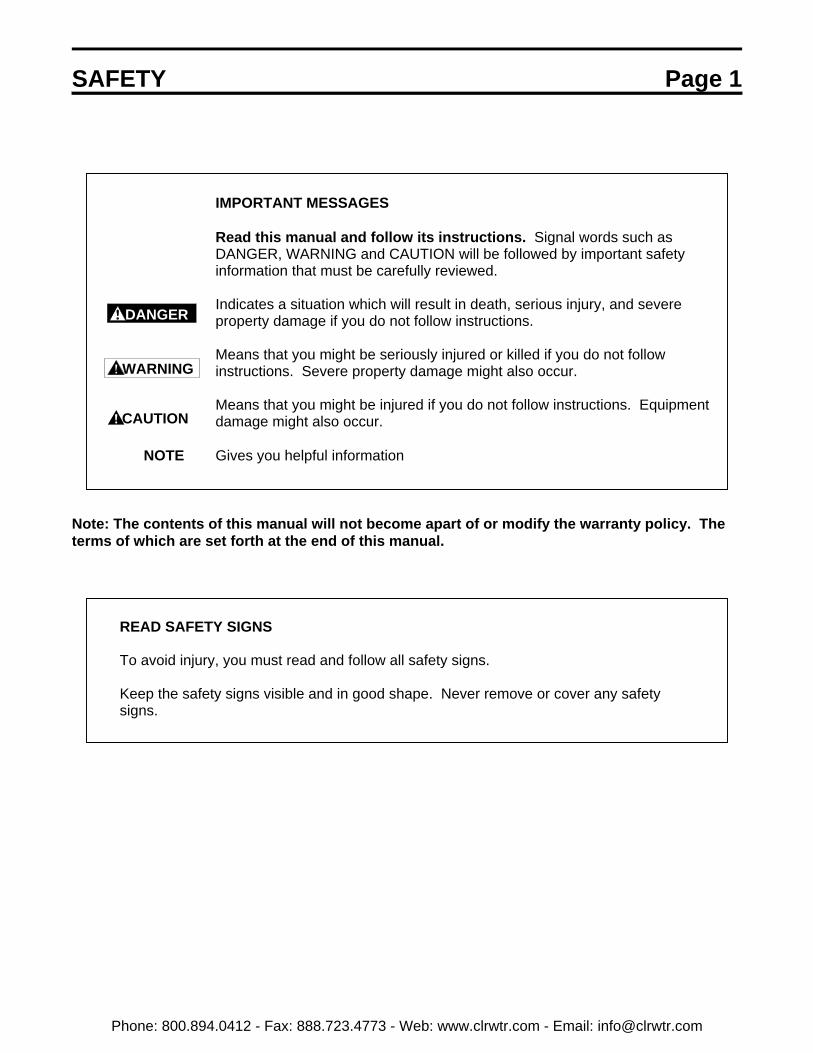
IMPORTANT MESSAGES
Read this manual and follow its instructions. Signal words such asDANGER, WARNING and CAUTION will be followed by important safetyinformation that must be carefully reviewed.
Indicates a situation which will result in death, serious injury, and severeproperty damage if you do not follow instructions.
Means that you might be seriously injured or killed if you do not followinstructions. Severe property damage might also occur.
Means that you might be injured if you do not follow instructions. Equipmentdamage might also occur.
NOTE Gives you helpful information
Note: The contents of this manual will not become apart of or modify the warranty policy. Theterms of which are set forth at the end of this manual.
READ SAFETY SIGNS
To avoid injury, you must read and follow all safety signs.
Keep the safety signs visible and in good shape. Never remove or cover any safetysigns.
DANGER
WARNING
CAUTION
Phone: 800.894.0412 - Fax: 888.723.4773 - Web: www.clrwtr.com - Email: [email protected]

Page 2 SAFETY
QUALIFIED OPERATORS ONLY
Only qualified persons are to install, operate, or service this equipment according to allapplicable codes and established safety practices.
A qualified person must:
1) Carefully read the entire instruction manual.2) Be skilled in the installation, construction or operation of the equipment and
aware of the hazards involved.3) Be trained and authorized to safely energize, de-energize, clear, ground,
lockout and tag circuits in accordance with established safety practices.4) Be trained and authorized to perform the service, maintenance or repair of
this equipment.5) Be trained in the proper care and use of protective equipment such as rubber
gloves, hard hat, safety glasses, face shield, flash clothing, etc. inaccordance with established practices.
6) Be trained in rendering first aid.
SAFETY CODES
Toshiba HV6FS vacuum circuit breakers are designed and built in accordance with JISC 4603-1990 and JEC-2300-1985. Installations must comply with all applicable stateand local codes, adhere to all applicable National Electric Code (NFPA 70) standardsand instructions provided in this manual.
Phone: 800.894.0412 - Fax: 888.723.4773 - Web: www.clrwtr.com - Email: [email protected]

SAFETY Page 3
HAZARDOUS VOLTAGE will cause severe injury, death, fire, explosion andproperty damage.
• Turn off and lock out Primary and Control Circuit Power before servicing.
• Keep all panels and covers securely in place.
• Never Defeat, Modify, or Bypass any Safety Interlocks
• Qualified Operators only
DANGER
Phone: 800.894.0412 - Fax: 888.723.4773 - Web: www.clrwtr.com - Email: [email protected]
Page 4 TABLE OF CONTENTSSAFETY....................................................................................................................................................1
INTRODUCTION ......................................................................................................................................7
GENERAL DESCRIPTION .......................................................................................................................8
Components..................................................................................................................................8Indicators and Controls .................................................................................................................9
RECEIVING, INSPECTION AND HANDLING........................................................................................10
Receiving and Unpacking ...........................................................................................................10Acceptance Inspection................................................................................................................10Handling and Moving ..................................................................................................................11
INSTALLATION......................................................................................................................................12
Rating Verification.......................................................................................................................12Mounting the Circuit Breaker to a Panel .....................................................................................13Mounting Directly to a Shelf ........................................................................................................15Main Circuit Cable Connections..................................................................................................16Ground Connections ...................................................................................................................17Control Circuit Connections ........................................................................................................18
PRE-ENERGIZATION CHECK ..............................................................................................................19
General .......................................................................................................................................19Electrical Checks ........................................................................................................................19
OPERATION...........................................................................................................................................20
Manual Operation........................................................................................................................20Electrical Operation.....................................................................................................................21Undervoltage Trip........................................................................................................................25
MAINTENANCE .....................................................................................................................................26
Maintenance Program.................................................................................................................26Maintenance Record...................................................................................................................26Servicing Equipment ...................................................................................................................26Inspection and Maintenance Types ............................................................................................27Table 1. Tightening Torques ......................................................................................................27Table 2. Check Points for Periodic Inspection ...........................................................................28Vacuum Check............................................................................................................................30
DISPOSAL..............................................................................................................................................32
STORAGE ..............................................................................................................................................33
Storage........................................................................................................................................33Inspection During Storage...........................................................................................................33
SPECIFICATIONS..................................................................................................................................34
Phone: 800.894.0412 - Fax: 888.723.4773 - Web: www.clrwtr.com - Email: [email protected]
TABLE OF CONTENTS Page 5
Table 3. Ratings – Manual Operation HV6FS-MU and HV6FS-ML Types ................................34
WARRANTY AND LIMITATION OF LIABILITY.....................................................................................35
Phone: 800.894.0412 - Fax: 888.723.4773 - Web: www.clrwtr.com - Email: [email protected]

INTRODUCTION Page 7 It is the intent of this manual to provide a guide for safely installing, operating and maintaining Toshibavacuum circuit breakers. This manual consists of a section of general safety instructions and is markedthroughout with warning symbols. Read this manual thoroughly before installation, operation andmaintenance of this equipment.
This manual and all accompanying drawings should be considered a permanent part of the equipment.They should be readily available for review and reference at all times. This manual is not intended tocover all details, combinations, or variations of the equipment. Always refer to drawings accompanyingthe equipment for additional details.
All safety warnings must be followed to ensure personal safety. General safety instructions arefound on pages 1 through 3. Read and save these instructions for future reference.
Follow all precautions to attain proper equipment performance and longevity.
Dimensions shown in the manual are in metric and/or their English equivalent.
This manual is divided into major sections of interest, as follows:
GENERAL DESCRIPTION – Provides a description of the equipment, information on majorcomponents and how they function, plus rating information.
RECEIVING, INSPECTION AND HANDLING – Describes procedures for receiving, unpacking,inspecting, handling, lifting and moving the circuit breaker.
INSTALLATION – Provides information on installing the circuit breaker in the switchgear cell along withbreaker racking procedures.
PRE-ENERGIZATION CHECK – Provides a checklist for preparing the equipment for energization.
OPERATION – Provides information on manual and electrical operation of the circuit breaker, circuitdiagrams, operating sequence description and operation of circuit breaker optional accessories.
MAINTENANCE – Lists the basic maintenance procedures for this equipment necessary for safe andreliable operation.
DISPOSAL – Lists procedures for the safe disposal of the equipment when the service life has expired.
STORAGE – Provides guidelines for storing new equipment for an extended period of time.
SPECIFICATIONS – Covers ratings and other specifications of the circuit breaker.
WARRANTY AND LIMITATION OF LIABILITY – Details Toshiba International Corporation’s standardwarranty terms.
Phone: 800.894.0412 - Fax: 888.723.4773 - Web: www.clrwtr.com - Email: [email protected]
Page 8 GENERAL DESCRIPTION
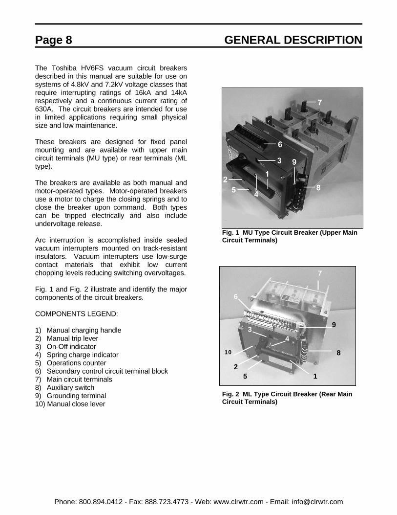
The Toshiba HV6FS vacuum circuit breakersdescribed in this manual are suitable for use onsystems of 4.8kV and 7.2kV voltage classes thatrequire interrupting ratings of 16kA and 14kArespectively and a continuous current rating of630A. The circuit breakers are intended for usein limited applications requiring small physicalsize and low maintenance.
These breakers are designed for fixed panelmounting and are available with upper maincircuit terminals (MU type) or rear terminals (MLtype).
The breakers are available as both manual andmotor-operated types. Motor-operated breakersuse a motor to charge the closing springs and toclose the breaker upon command. Both typescan be tripped electrically and also includeundervoltage release.
Arc interruption is accomplished inside sealedvacuum interrupters mounted on track-resistantinsulators. Vacuum interrupters use low-surgecontact materials that exhibit low currentchopping levels reducing switching overvoltages.
Fig. 1 and Fig. 2 illustrate and identify the majorcomponents of the circuit breakers.
COMPONENTS LEGEND:
1) Manual charging handle2) Manual trip lever3) On-Off indicator4) Spring charge indicator5) Operations counter6) Secondary control circuit terminal block7) Main circuit terminals8) Auxiliary switch9) Grounding terminal10) Manual close lever
Fig. 1 MU Type Circuit Breaker (Upper MainCircuit Terminals)
Fig. 2 ML Type Circuit Breaker (Rear MainCircuit Terminals)
6
34
7
9
10
25 1
8
Phone: 800.894.0412 - Fax: 888.723.4773 - Web: www.clrwtr.com - Email: [email protected]
GENERAL DESCRIPTION Page 9SAFETY DEVICES
Safety interlocks and guards are provided as anintegral part of the equipment design. Thesedevices are provided for safety to the operator.
Never defeat, modify orbypass any safety devices,interlocks or operatingmechanism. This wouldmake the equipmentunsafe. Fire, explosion,severe injury, death andproperty damage couldoccur.
Do not operate thisequipment unless allcovers and panels are inplace.
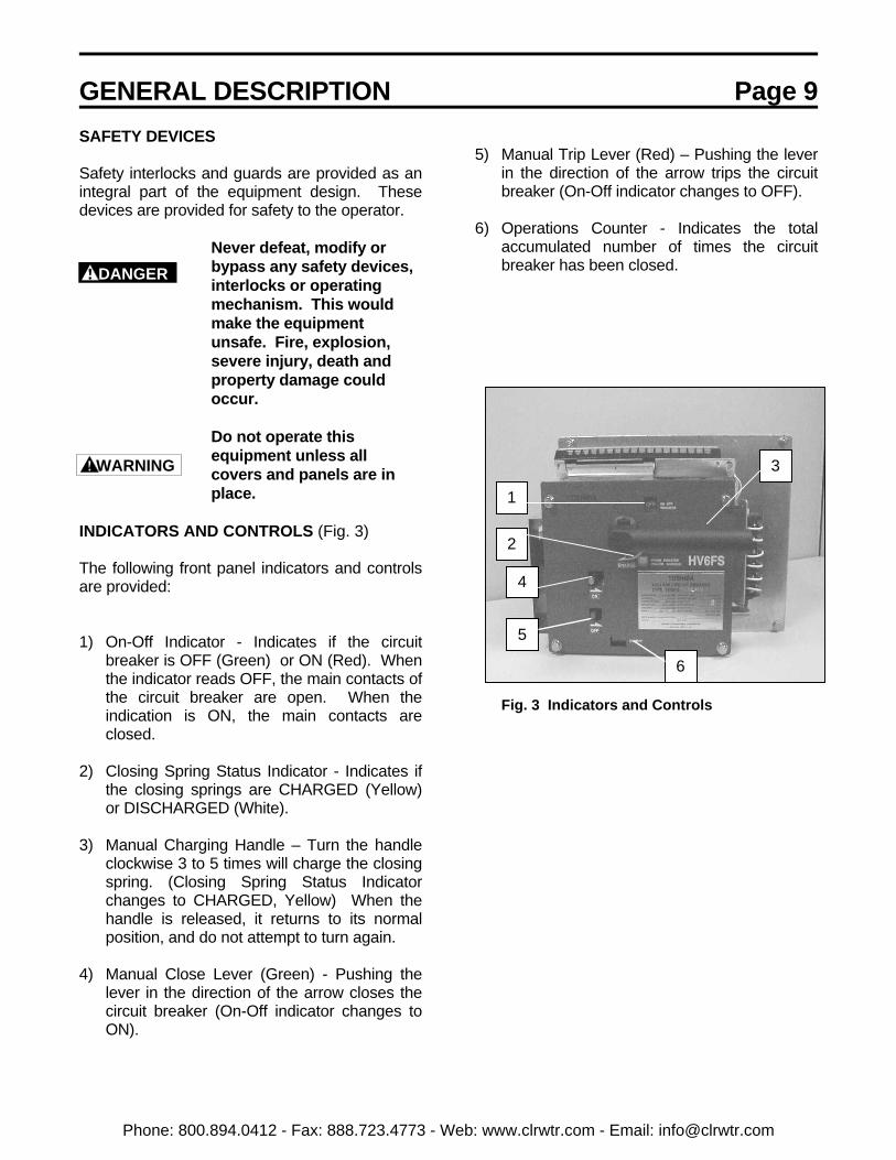
INDICATORS AND CONTROLS (Fig. 3)
The following front panel indicators and controlsare provided:
1) On-Off Indicator - Indicates if the circuit
breaker is OFF (Green) or ON (Red). Whenthe indicator reads OFF, the main contacts ofthe circuit breaker are open. When theindication is ON, the main contacts areclosed.
2) Closing Spring Status Indicator - Indicates if
the closing springs are CHARGED (Yellow)or DISCHARGED (White).
3) Manual Charging Handle – Turn the handle
clockwise 3 to 5 times will charge the closingspring. (Closing Spring Status Indicatorchanges to CHARGED, Yellow) When thehandle is released, it returns to its normalposition, and do not attempt to turn again.
4) Manual Close Lever (Green) - Pushing thelever in the direction of the arrow closes thecircuit breaker (On-Off indicator changes toON).
5) Manual Trip Lever (Red) – Pushing the lever
in the direction of the arrow trips the circuitbreaker (On-Off indicator changes to OFF).
6) Operations Counter - Indicates the total
accumulated number of times the circuitbreaker has been closed.
Fig. 3 Indicators and Controls
DANGER
WARNING
1
5
4
2
3
6
Phone: 800.894.0412 - Fax: 888.723.4773 - Web: www.clrwtr.com - Email: [email protected]
Page 10 INSTALLATION
RECEIVING AND UNPACKING
The circuit breaker units are subjected to factoryproduction testing prior to being packed andshipped.
ACCEPTANCE INSPECTION
Confirm that the circuit breaker unit is complete,correct as specified and undamaged fromshipment and handling.
Upon receipt of the equipment, do the following:
1) Make an immediate inspection for damagethat might have occurred during shipment. Ifdamage is discovered, it should be notedwith the carrier prior to accepting theshipment, if possible.
2) Carefully unpack the equipment sufficiently tocheck for missing parts or concealeddamage.
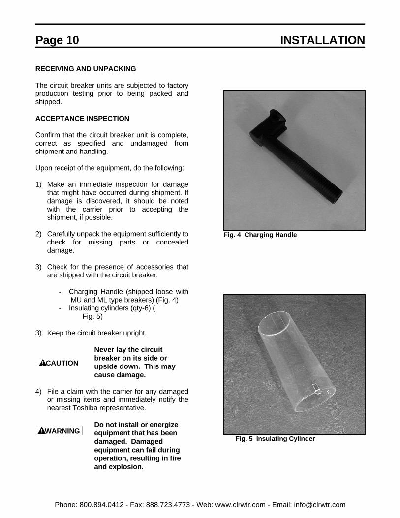
3) Check for the presence of accessories thatare shipped with the circuit breaker:
- Charging Handle (shipped loose withMU and ML type breakers) (Fig. 4)
- Insulating cylinders (qty-6) (Fig. 5)
3) Keep the circuit breaker upright.
Never lay the circuitbreaker on its side orupside down. This maycause damage.
4) File a claim with the carrier for any damagedor missing items and immediately notify thenearest Toshiba representative.
Do not install or energizeequipment that has beendamaged. Damagedequipment can fail duringoperation, resulting in fireand explosion.
Fig. 4 Charging Handle
Fig. 5 Insulating Cylinder
CAUTION
WARNING
Phone: 800.894.0412 - Fax: 888.723.4773 - Web: www.clrwtr.com - Email: [email protected]

INSTALLATION Page 11
HANDLING AND MOVING
When handling and moving the circuit breaker,the techniques shown in this section may beused.
Care and caution should be used when handlingthe circuit breaker units to avoid damage to theequipment and personal injury. Always keep thecircuit breaker in a generally upright position.
Refer to Fig. 6 and Fig. 7 for the correctmethods of lifting and moving the circuitbreakers.
Fig. 6 Correct Method for Handling the MUType Circuit Breaker
Fig. 7 Correct Method for Handling the MLType Circuit Breaker
Phone: 800.894.0412 - Fax: 888.723.4773 - Web: www.clrwtr.com - Email: [email protected]
Page 12 INSTALLATION
Do not install thisequipment in areas whereunusual service conditionsexist. Using this equipmentin other than usual serviceconditions can result inequipment failure.
Toshiba HV6FS circuit breakers are intended foruse in usual service conditions as defined inIEEE C37.20.2. The temperature of the coolingair (ambient air temperature) surrounding thebreaker should be between the limits of -5°C(23°F) and +40°C (104°F). The altitude of theequipment installation should not exceed 3300 ft(1000 m).
In particular, avoid the following installationconditions:
- Excessive dust- Corrosive gases- Extreme variations in temperature- Very high or low humidity- Vibrations- Inclined locations
If there is a chance that condensation can occur
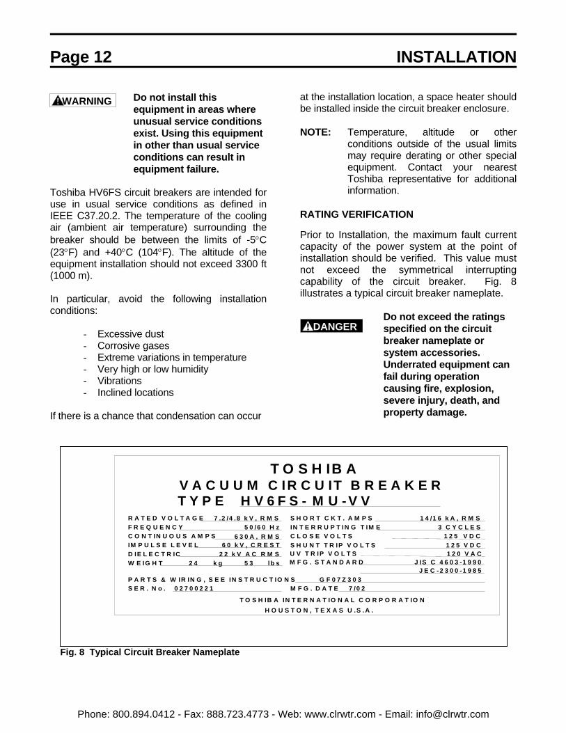
Fig. 8 Typical Circuit Breaker Nameplate
at the installation location, a space heater shouldbe installed inside the circuit breaker enclosure.
NOTE: Temperature, altitude or otherconditions outside of the usual limitsmay require derating or other specialequipment. Contact your nearestToshiba representative for additionalinformation.
RATING VERIFICATION
Prior to Installation, the maximum fault currentcapacity of the power system at the point ofinstallation should be verified. This value mustnot exceed the symmetrical interruptingcapability of the circuit breaker. Fig. 8illustrates a typical circuit breaker nameplate.
Do not exceed the ratingsspecified on the circuitbreaker nameplate orsystem accessories.Underrated equipment canfail during operationcausing fire, explosion,severe injury, death, andproperty damage.
WARNING
DANGER
H O U S T O N , T E X A S U .S . A .
R A T E D V O L T A G EF R E Q U E N C Y
IM P U L S E L E V E LD IE L E C T R IC
S E R . N o .P A R T S & W IR IN G , S E E IN S T R U C T IO N S
C O N T IN U O U S A M P S
W E IG H T
S H O R T C K T . A M P SIN T E R R U P T IN G T IM E
V A C U U M C IR C U IT B R E A K E R
U V T R IP V O L T SM F G . S T A N D A R D
S H U N T T R IP V O L T S
T O S H IB A IN T E R N A T IO N A L C O R P O R A T IO N
C L O S E V O L T S 5 0 /6 0 H z
2 2 k V A C R M S 6 0 k V , C R E S T
6 3 0 A , R M S
k g
M F G . D A T E
lb s
H V 6 F S - 7 .2 /4 .8 k V , R M S
T Y P E
J IS C 4 6 0 3 -1 9 9 0 J E C -2 3 0 0 -1 9 8 5
1 2 0 V A CV D CV D C
1 4 /1 6 k A , R M S3 C Y C L E S
2 4 5 3
1 2 51 2 5
G F 0 7 Z 3 0 3
M U - V V
0 2 7 0 0 2 2 1 7 /0 2
T O S H IB A
Phone: 800.894.0412 - Fax: 888.723.4773 - Web: www.clrwtr.com - Email: [email protected]
INSTALLATION Page 13
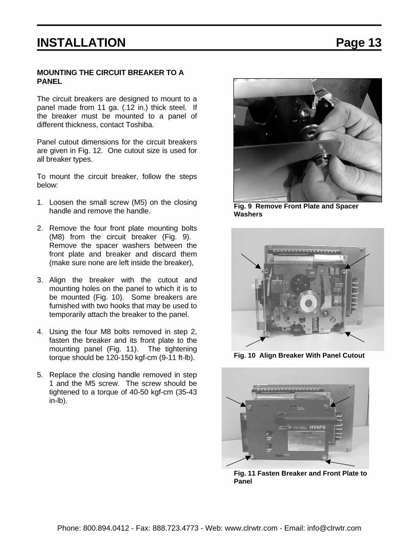
MOUNTING THE CIRCUIT BREAKER TO APANEL
The circuit breakers are designed to mount to apanel made from 11 ga. (.12 in.) thick steel. Ifthe breaker must be mounted to a panel ofdifferent thickness, contact Toshiba.
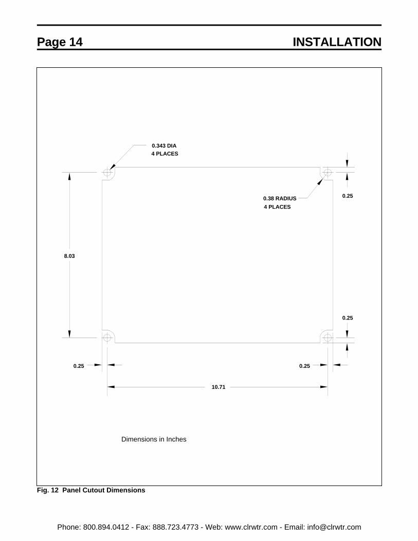
Panel cutout dimensions for the circuit breakersare given in Fig. 12. One cutout size is used forall breaker types.
To mount the circuit breaker, follow the stepsbelow:
1. Loosen the small screw (M5) on the closinghandle and remove the handle.
2. Remove the four front plate mounting bolts(M8) from the circuit breaker (Fig. 9). Remove the spacer washers between thefront plate and breaker and discard them(make sure none are left inside the breaker),
3. Align the breaker with the cutout andmounting holes on the panel to which it is tobe mounted (Fig. 10). Some breakers arefurnished with two hooks that may be used totemporarily attach the breaker to the panel.
4. Using the four M8 bolts removed in step 2,fasten the breaker and its front plate to themounting panel (Fig. 11). The tighteningtorque should be 120-150 kgf-cm (9-11 ft-lb).
5. Replace the closing handle removed in step1 and the M5 screw. The screw should betightened to a torque of 40-50 kgf-cm (35-43in-lb).
Fig. 9 Remove Front Plate and SpacerWashers
Fig. 10 Align Breaker With Panel Cutout
Fig. 11 Fasten Breaker and Front Plate toPanel
Phone: 800.894.0412 - Fax: 888.723.4773 - Web: www.clrwtr.com - Email: [email protected]
Page 14 INSTALLATION
Fig. 12 Panel Cutout Dimensions
10.71
0.38 RADIUS4 PLACES
0.343 DIA4 PLACES
0.25
0.25
0.25 0.25
8.03
Dimensions in Inches
Phone: 800.894.0412 - Fax: 888.723.4773 - Web: www.clrwtr.com - Email: [email protected]

INSTALLATION Page 15
MOUNTING DIRECTLY TO A SHELF
The shelf should be flat and level within ± 0.5mm (± 0.02 in.). If there are any noticeable gapsbetween the breaker and the shelf, fill them inusing flat washers as spacers.
Check to make sure the breaker On-Off indicatorshows OFF (green), then mount it by followingthe steps below:
1. Fasten the breaker onto steel angles or to aflate plate (Fig. 13). Use M8 hex head bolts(either 50 mm or 35 mm). The tighteningtorque should be 120-150 kgf-cm (9-11 ft-lb).
2. Either mounting method shown in (Fig. 14)may be used.
Fig. 13 Mounting Breaker to Flat Plate orAngles
Fig. 14 Optional Hardware Orientation
ANGLE
PANEL
M8 x 35MM OR M8 x 50MM BOLT
Phone: 800.894.0412 - Fax: 888.723.4773 - Web: www.clrwtr.com - Email: [email protected]

Page 16 INSTALLATION
MAIN CIRCUIT CABLE CONNECTIONS
Cables that connect to the circuit breaker shouldbe routed to avoid interference with sharp edgesand moving parts. Minimum bending radius forthe type of cable used should be observed.
Power cables should be braced and/or laced towithstand short-circuit forces wherever suchcables are unsupported. Power cables shouldbe adequately sized to carry the maximumcontinuous current in accordance with NECrequirements and should have an adequatevoltage rating. Cables should be dressed andterminated as appropriate to the voltage classand cable manufacturer’s recommendations.When terminating shielded cables, usetermination kits appropriate for the systemvoltage to taper the insulation and reduceelectrical stress. Follow the manufacturer’sinstallation instructions provided with thetermination kit.
To connect cables, follow the steps below:
1. Pass the cable through the insulatingcylinder (six cylinders are supplied with thecircuit breaker) (Fig. 15).
2. Fasten the cable to the main circuit terminal(Fig. 16). Use 35 mm Class 8.8 M10 or M12hex head bolts, 2 flat washers, a lock washerand a nut. While securely preventing the boltfrom rotating with a wrench, torque the nut to250-315 kgf-cm (18-23 ft-lb) for M10 bolts or450-565 kgf-cm (32-41 ft-lb) for M12 bolts.
Use two wrenches to torquethe connection to preventapplying excessive force tothe terminal that candamage the frame.
3. Fasten the insulating cylinder in place, thencheck to make sure that the hook is engaged(Fig. 17).
Fig. 15 Pass Cable Through InsulatingCylinder
Fig. 16 Fasten Cable to Main CircuitTerminal
Fig. 17 Fasten Insulating Cylinder
CAUTION
Phone: 800.894.0412 - Fax: 888.723.4773 - Web: www.clrwtr.com - Email: [email protected]

INSTALLATION Page 17
GROUND CONNECTIONS
The circuit breaker must be grounded inaccordance with the requirements of the NationalElectrical Code, Article 250 or applicable localstandards.
Proper groundingconnections must be madeto the circuit breaker beforeincoming power is applied.
It is very important that the circuit breaker and itsenclosure be adequately grounded to protect theoperator from injury in the event of short circuitsor other abnormal occurrences and to ensurethat the metal parts of the equipment, other thanlive parts, remain at ground potential.
For MU type circuit breakers, the ground terminalis on the left side of the operating mechanism asviewed from the rear of the breaker. To makethe ground connection, first remove the fasteningM6 hex head bolt and crimp-on terminal(provided with the breaker) and crimp theterminal to the end of the ground wire (Fig. 18).Then, reattach the terminal using the same boltpreviously removed and torque to 50-65 kgf-cm(43-56 in-lb).
For ML type circuit breakers, the ground terminalis on the left side of the terminal block as viewedfrom the rear of the breaker (Fig. 19). The sameinstructions as for the MU breaker above shouldbe followed to attach the ground wire.
Fig. 18 Ground Connection for MU TypeBreaker
Fig. 19 Ground Connection for ML TypeBreakers
WARNING
Phone: 800.894.0412 - Fax: 888.723.4773 - Web: www.clrwtr.com - Email: [email protected]

Page 18 INSTALLATION
CONTROL CIRCUIT CONNECTIONS
Control circuit wiring is connected to theterminal block on the top of the operatingmechanism (Fig. 20). Connect control wires inaccordance with the appropriate wiring diagramshown in Fig. 28 through Fig. 29 in theOPERATION section of this manual.
On the MU type breakers, connections toauxiliary contacts are made directly to theauxiliary switch (Fig. 21).
On the ML type breakers, connections toauxiliary contacts are made to a terminal blockon top of the operating mechanism (Fig. 22).
Fig. 20 Connection to Control TerminalBlock
Fig. 21 Auxiliary Contact Connections onMU Type Breakers
Fig. 22 Auxiliary Contact Connections on MLType Breakers
Phone: 800.894.0412 - Fax: 888.723.4773 - Web: www.clrwtr.com - Email: [email protected]

PRE-ENERGIZATION CHECK Page 19
GENERAL
BEFORE ENERGIZING THE CIRCUITBREAKER for the first time, follow the procedurebelow to verify that the equipment is properlyinstalled and functional.
Hazardous Voltage. Turn offand lock out all primary andcontrol circuit powersources prior to performingthis pre-energization check.
Do not operate thisequipment until a completesafety inspection has beenmade.
Do not energize damagedequipment that has notbeen repaired or verified.
Do not remove, cover ordestroy any safety signs.
Do not operate thisequipment until all panelsand covers have beeninstalled.
All blocks or other temporary braces used forshipment must be removed.
Before closing the enclosure, all metal chips,scrap wire and other debris left over frominstallation must be cleaned out.
Cover all unused openings. Install all panels,guards and covers.
A supply of spare parts should beestablished.
Instruction manuals and diagrams should becollected and filed.
ELECTRICAL CHECKS
Electrical shock hazard. Do not touch energizedcomponents during a testusing auxiliary power.
An electrical insulation resistance test shouldbe performed to verify that the circuit breakerand associated field wiring are free fromshort circuits and grounds. Refer to theMAINTENANCE Section of this manual foradditional information.
Hazardous voltages arepresent during dielectrictesting which can result inserious injury or death. High potential tests shouldbe performed only byqualified personnel.
The circuit breaker must be set to the OFFposition before energizing incoming power.
DANGER
WARNING
WARNING
WARNING
WARNING
WARNING
WARNING
Phone: 800.894.0412 - Fax: 888.723.4773 - Web: www.clrwtr.com - Email: [email protected]

Page 20 OPERATION
MANUAL OPERATION
Powerful springs. Do notplace your hands or anypart of your body insidethe circuit breaker whilethe indicators showCHARGED (yellow) or ON(red).
To avoid damaging themechanism, do not closethe circuit breaker whenthe On-Off Indicator showsON (red).
MANUAL CLOSING (Motor-Operated MU andML Types):
1. Check to make sure that the On-Offindicator shows OFF (green).
2. Attach the charging handle to the breaker if itis not already attached.
3. If the closing spring status indicator showsDISCHARGED (white):
Turn the charging handle clockwise 3 to 5times to charge the closing spring (Fig. 23).(Closing Spring Status Indicator changes toCHARGED, Yellow) When the handle isreleased, it returns to its normal position, anddo not attempt to turn again.
If the closing spring status indicator showsCHARGED (yellow):
Do not attempt to turn handle.
Pushing the Green lever (Fig. 24) in thedirection of the arrow closes the circuitbreaker (On-Off indicator changes to ON)
Fig. 23 Preparing to Manually ChargeBreaker
Fig. 24 Manually Closing Breaker
WARNING
CAUTION
Phone: 800.894.0412 - Fax: 888.723.4773 - Web: www.clrwtr.com - Email: [email protected]

OPERATION Page 21
MANUAL OPENING (All Types):
1. Push the trip lever in the direction of thearrow (Fig. 25).
2. The On-Off indicator changes to OFF(green).
3. The Spring Charge Indicator changes toWHITE.
ELECTRICAL OPERATION
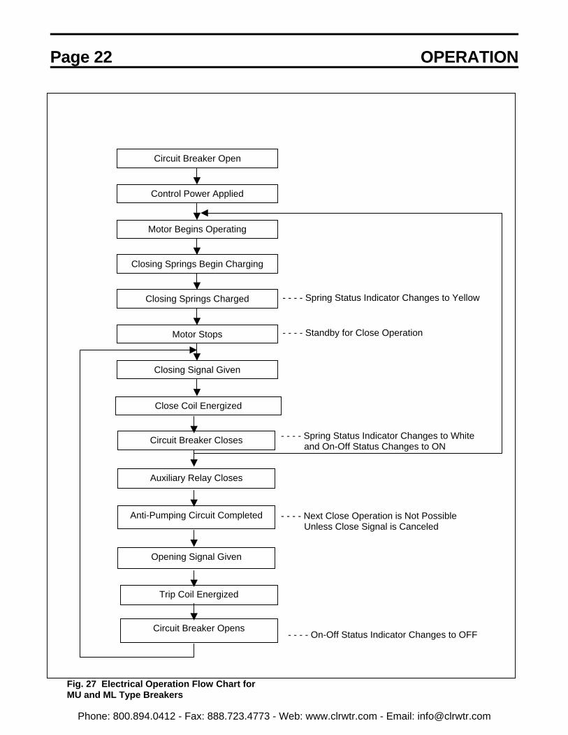
The flow chart shown in Fig. 27 illustrates thesequence of electrical operation of the MU andML type circuit breakers.
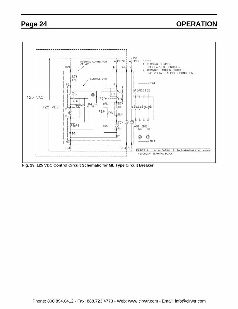
Refer to Fig. 26 and the circuit breakerschematics shown in Fig. 28 through Fig. 29 fordetermining external control circuit connectionsto the circuit breaker.
Fig. 25 Manually Opening Breaker
SYMBOL DESCRIPTIONM MotorTC Voltage Trip CoilCC Close CoilUV Undervoltage Trip Coil
a1 to a3 Auxiliary Contacts (N.O.)b1 to b2 Auxiliary Contacts (N.C.)
X Control RelayX-a Control Relay Contact (N.O.)X-b Control Relay Contact (N.C.)Y Auxiliary Relay
Y-b Auxiliary Relay Contact (N.C.)LS Limit SwitchR ResistorD DiodeC Capacitor
RL Red LampGL Green Lamp
Fig. 26 Legend for Schematics
Phone: 800.894.0412 - Fax: 888.723.4773 - Web: www.clrwtr.com - Email: [email protected]
Page 22 OPERATION
Fig. 27 Electrical Operation Flow Chart forMU and ML Type Breakers
Circuit Breaker Open
Control Power Applied
Motor Begins Operating
Closing Springs Begin Charging
Closing Springs Charged
Motor Stops
Closing Signal Given
- - - - Spring Status Indicator Changes to Yellow
- - - - Standby for Close Operation
Close Coil Energized
Circuit Breaker Closes
Auxiliary Relay Closes
Anti-Pumping Circuit Completed
Opening Signal Given
Trip Coil Energized
Circuit Breaker Opens
- - - - Spring Status Indicator Changes to White and On-Off Status Changes to ON
- - - - Next Close Operation is Not Possible Unless Close Signal is Canceled
- - - - On-Off Status Indicator Changes to OFF
Phone: 800.894.0412 - Fax: 888.723.4773 - Web: www.clrwtr.com - Email: [email protected]

OPERATION Page 23
Fig. 28 125 VDC Control Circuit Schematic for MU Type Circuit Breaker
Phone: 800.894.0412 - Fax: 888.723.4773 - Web: www.clrwtr.com - Email: [email protected]
Page 24 OPERATION
Fig. 29 125 VDC Control Circuit Schematic for ML Type Circuit Breaker
Phone: 800.894.0412 - Fax: 888.723.4773 - Web: www.clrwtr.com - Email: [email protected]
OPERATION Page 25
UNDERVOLTAGE TRIP
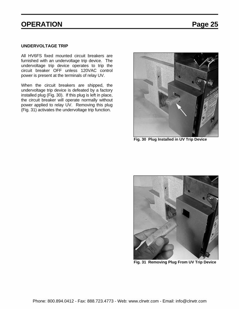
All HV6FS fixed mounted circuit breakers arefurnished with an undervoltage trip device. Theundervoltage trip device operates to trip thecircuit breaker OFF unless 120VAC controlpower is present at the terminals of relay UV.
When the circuit breakers are shipped, theundervoltage trip device is defeated by a factoryinstalled plug (Fig. 30). If this plug is left in place,the circuit breaker will operate normally withoutpower applied to relay UV. Removing this plug(Fig. 31) activates the undervoltage trip function.
Fig. 30 Plug Installed in UV Trip Device
Fig. 31 Removing Plug From UV Trip Device
Phone: 800.894.0412 - Fax: 888.723.4773 - Web: www.clrwtr.com - Email: [email protected]

Page 26 DISPOSAL
MAINTENANCE PROGRAM
In order to ensure continued reliable and safeoperation of the equipment, a program ofperiodic maintenance must be established.Operating and environmental conditions willusually dictate the frequency of inspectionrequired. NFPA Publication 70B "ElectricalEquipment Maintenance" may be used as aguide for setting up the maintenance program.
Contact with energizedcomponents can causesevere injury, death andproperty damage. Turn offand lock-out primary andcontrol circuit power beforeservicing.
Improper maintenance cancause severe injury, deathand property damage. Onlyqualified and authorizedpersons are to install,operate or service thisequipment.
Grease is conductive. Donot allow grease or anyother substances tocontaminate insulatingmaterials. Contaminatedinsulators can allow ashort-circuit or groundfault to occur.
NOTE: Refer to the SAFETY section of thismanual for important information.
MAINTENANCE RECORD
Keep a permanent record of all maintenancework. At a minimum, this record should includeinformation on:
1) Items inspected2) Reports of any testing3) Equipment condition4) Corrective actions or adjustments5) Date of work
6) Comments
The degree of detail of the record will dependsomewhat on the operating conditions.
SERVICING EQUIPMENT
For your safety, turn off and lock out main andcontrol circuit power before servicing the circuitbreaker. Certain minimum safety proceduresmust be followed:
1) Only qualified personnel should attemptthis service.
2) Never perform service on or next toexposed components energized with linevoltage.
Failure to adhere to thesesafety procedures canresult in severe injury,death and propertydamage.
WARNING
DANGER
WARNING
WARNING
Phone: 800.894.0412 - Fax: 888.723.4773 - Web: www.clrwtr.com - Email: [email protected]

MAINTENANCE Page 27
RECOMMENDED INSPECTION ANDMAINTENANCE TYPES
NOTE: Refer to the SAFETY section of thismanual for important information.
A. Acceptance Inspection
This inspection confirms that the circuitbreaker unit is complete, correct as specified,and undamaged from shipment. Theprocedure for this inspection is outlined in theRECEIVING, INSPECTION AND HANDLINGsection of this manual.
B. Patrol Inspection
Inspection is made of the condition of thecircuit breaker while it is energized. Checkthat no unusual sounds or smells existexternally.
Inspection Frequency: Once every 6 months
C. Periodic Inspection
Inspection is performed with the circuitbreaker de-energized. The lubrication ofsliding and rotating parts is checked and themechanism is lubricated if needed.
Inspection Frequency: Once every 1-3 yearsor every 3000 operations (normal). Onceevery 6 years (detailed).
Refer to Table 2 for the schedule of PeriodicInspections.
D. Unscheduled Inspection
Inspections are implemented as required.
Inspection Frequency: As needed
NOTE: The inspection frequency and pointsto be inspected may vary from theabove recommendations dependingon the status of use, frequency ofswitching, amount of currentinterrupted and other factors.
Table 1 Tightening Torques
ScrewNominal
Dia.Tightening Torque
M4 15-20 kgf-cm13-17 in-lb
M5 30-40 kgf-cm26-34 in-lb
M6 50-65 kgf-cm43-56 in-lb
M8 120-150 kgf-cm9-11 ft-lb
M10 250-315 kgf-cm18-23 ft-lb
M12 450-565 kgf-cm32-41 ft-lb
Phone: 800.894.0412 - Fax: 888.723.4773 - Web: www.clrwtr.com - Email: [email protected]
Page 28 DISPOSAL
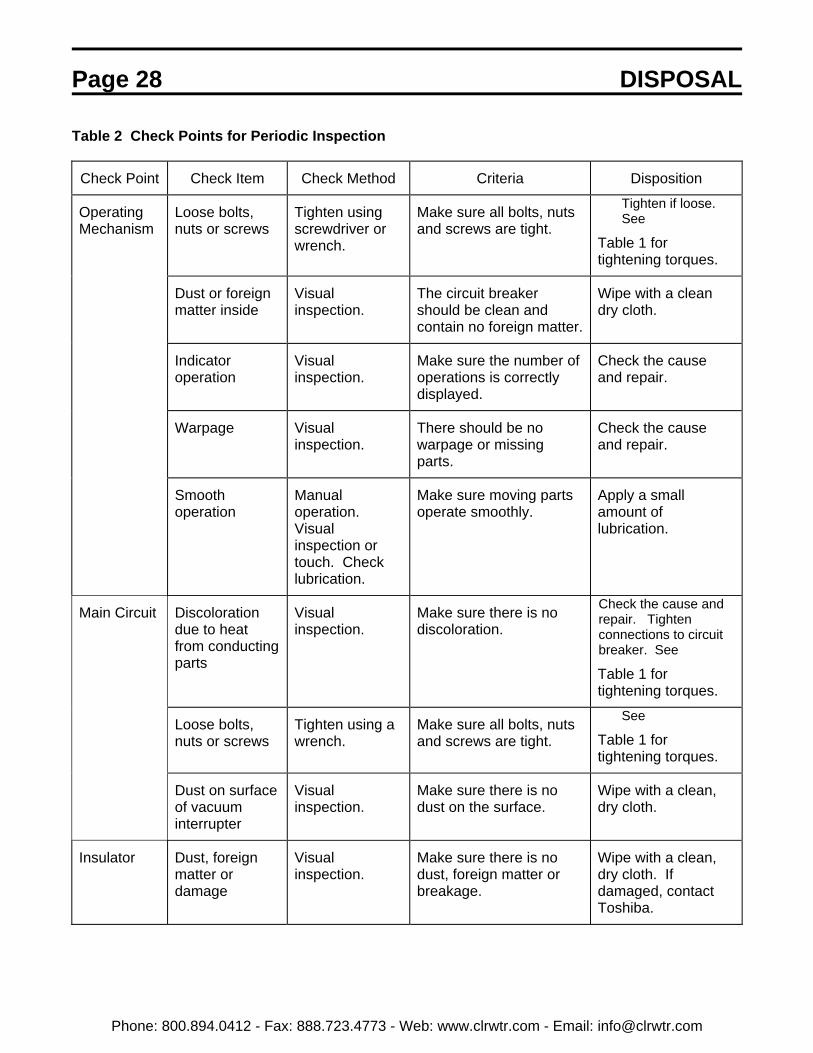
Table 2 Check Points for Periodic Inspection
Check Point Check Item Check Method Criteria Disposition
OperatingMechanism
Loose bolts,nuts or screws
Tighten usingscrewdriver orwrench.
Make sure all bolts, nutsand screws are tight.
Tighten if loose. See
Table 1 fortightening torques.
Dust or foreignmatter inside
Visualinspection.
The circuit breakershould be clean andcontain no foreign matter.
Wipe with a cleandry cloth.
Indicatoroperation
Visualinspection.
Make sure the number ofoperations is correctlydisplayed.
Check the causeand repair.
Warpage Visualinspection.
There should be nowarpage or missingparts.
Check the causeand repair.
Smoothoperation
Manualoperation. Visualinspection ortouch. Checklubrication.
Make sure moving partsoperate smoothly.
Apply a smallamount oflubrication.
Main Circuit Discolorationdue to heatfrom conductingparts
Visualinspection.
Make sure there is nodiscoloration.
Check the cause andrepair. Tightenconnections to circuitbreaker. See
Table 1 fortightening torques.
Loose bolts,nuts or screws
Tighten using awrench.
Make sure all bolts, nutsand screws are tight.
See
Table 1 fortightening torques.
Dust on surfaceof vacuuminterrupter
Visualinspection.
Make sure there is nodust on the surface.
Wipe with a clean,dry cloth.
Insulator Dust, foreignmatter ordamage
Visualinspection.
Make sure there is nodust, foreign matter orbreakage.
Wipe with a clean,dry cloth. Ifdamaged, contactToshiba.
Phone: 800.894.0412 - Fax: 888.723.4773 - Web: www.clrwtr.com - Email: [email protected]

MAINTENANCE Page 29
Table 2. Check Points for Inspection (cont’d)
Check Point Check Item Check Method Criteria What to do
AuxiliarySwitch
Terminals looseor disconnected
Visualinspection. Tighten using ascrewdriver.
Make sure terminals arenot loose or disconnected.
Repair ifdisconnected. Tightenif loose. See
Table 1 for tighteningtorques.
Case/contacts Visualinspection.
Make sure there is nodamage or warping.
Replace if damagedor warped.
ControlCircuits
Smoothmovement ofmotor chargingmechanism
Energize thecontrol circuit.
Breaker (motor-operatedtype) should chargequickly and smoothly.
If the circuit fails tooperate, check thecause and repair.
Terminals looseor disconnected
Visualinspection. Tighten using ascrewdriver.
Make sure terminals arenot loose or disconnected.
Repair ifdisconnected. Tighten if loose. See
Table 1 fortightening torques.
InsulationResistanceMeasure-ment
Measure maincircuit to ground
Megger test at1000V.
Resistance should be500MΩ or greater.
Measurebetween maincircuit terminals
Megger test at1000V.
Resistance should be100MΩ or greater.
Measure controlcircuits toground
Megger test at500V.
Resistance should be2MΩ or greater.
If the insulationresistance is low,wipe off the vacuuminterrupter and otherinsulation surfaceswith a clean drycloth and thenrepeat the test.
Phone: 800.894.0412 - Fax: 888.723.4773 - Web: www.clrwtr.com - Email: [email protected]
Page 30 MAINTENANCE
VACUUM CHECK
A sufficient level of vacuum is necessary forproper performance of the vacuum interrupters.Although vacuum leaks are rare, the vacuumintegrity should be checked periodically. Therelationship between dielectric breakdownvoltage of the contact gap and internal vacuuminterrupter pressure has been found to begenerally predictable. Therefore, vacuuminterrupter integrity is checked by performing ahigh potential test across the open gap of theinterrupter.
TEST EQUIPMENT:
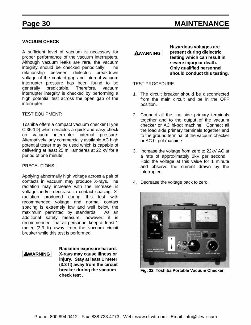
Toshiba offers a compact vacuum checker (TypeCI35-1D) which enables a quick and easy checkon vacuum interrupter internal pressure.Alternatively, any commercially available AC highpotential tester may be used which is capable ofdelivering at least 25 milliamperes at 22 kV for aperiod of one minute.
PRECAUTIONS:
Applying abnormally high voltage across a pair ofcontacts in vacuum may produce X-rays. Theradiation may increase with the increase involtage and/or decrease in contact spacing. X-radiation produced during this test withrecommended voltage and normal contactspacing is extremely low and well below themaximum permitted by standards. As anadditional safety measure, however, it isrecommended that all personnel keep at least 1meter (3.3 ft) away from the vacuum circuitbreaker while this test is performed.
Radiation exposure hazard.X-rays may cause illness orinjury. Stay at least 1 meter(3.3 ft) away from the circuitbreaker during the vacuumcheck test .
Hazardous voltages arepresent during dielectrictesting which can result insevere injury or death. Only qualified personnelshould conduct this testing.
TEST PROCEDURE:
1. The circuit breaker should be disconnectedfrom the main circuit and be in the OFFposition.
2. Connect all the line side primary terminals
together and to the output of the vacuumchecker or AC hi-pot machine. Connect allthe load side primary terminals together andto the ground terminal of the vacuum checkeror AC hi-pot machine.
3. Increase the voltage from zero to 22kV AC at
a rate of approximately 2kV per second. Hold the voltage at this value for 1 minuteand observe the current drawn by theinterrupter.
4. Decrease the voltage back to zero.
Fig. 32 Toshiba Portable Vacuum Checker
WARNING
WARNING
Phone: 800.894.0412 - Fax: 888.723.4773 - Web: www.clrwtr.com - Email: [email protected]
MAINTENANCE Page 31
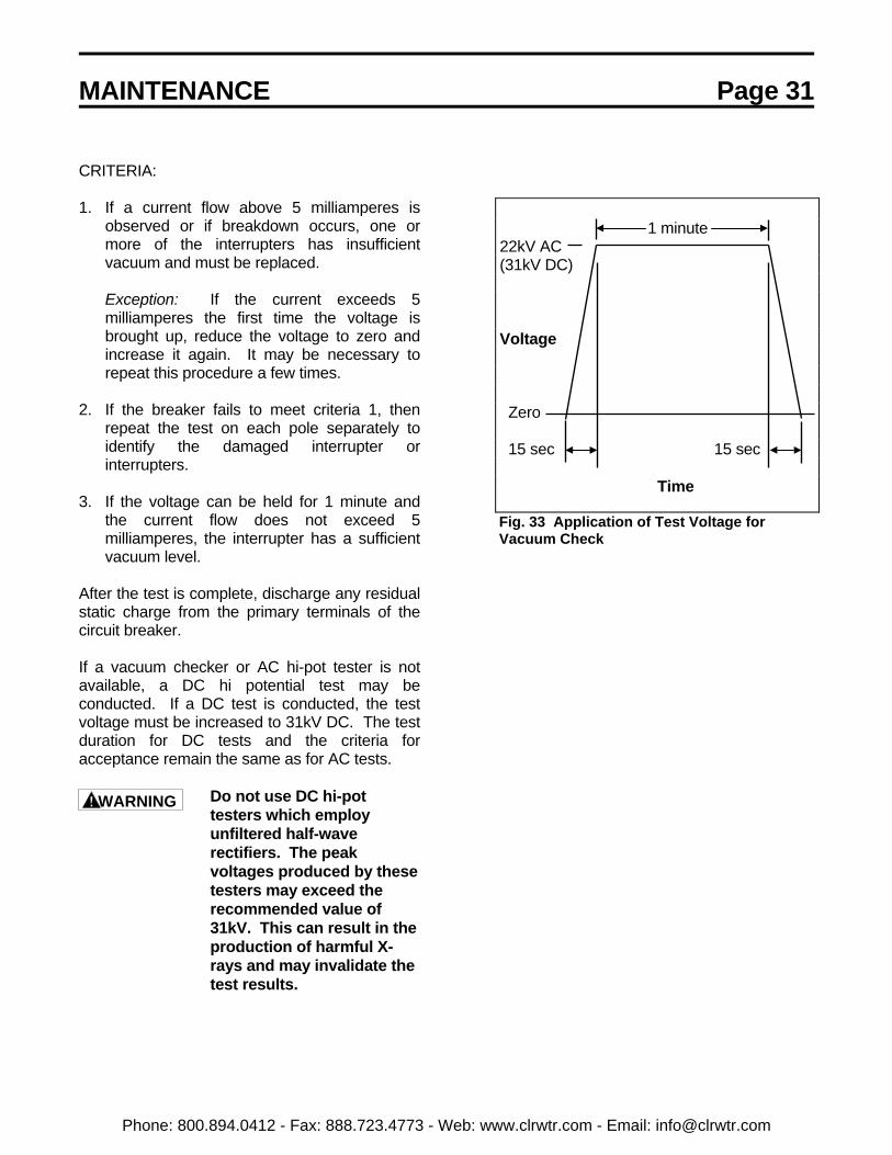
CRITERIA:
1. If a current flow above 5 milliamperes isobserved or if breakdown occurs, one ormore of the interrupters has insufficientvacuum and must be replaced.
Exception: If the current exceeds 5milliamperes the first time the voltage isbrought up, reduce the voltage to zero andincrease it again. It may be necessary torepeat this procedure a few times.
2. If the breaker fails to meet criteria 1, thenrepeat the test on each pole separately toidentify the damaged interrupter orinterrupters.
3. If the voltage can be held for 1 minute and
the current flow does not exceed 5milliamperes, the interrupter has a sufficientvacuum level.
After the test is complete, discharge any residualstatic charge from the primary terminals of thecircuit breaker.
If a vacuum checker or AC hi-pot tester is notavailable, a DC hi potential test may beconducted. If a DC test is conducted, the testvoltage must be increased to 31kV DC. The testduration for DC tests and the criteria foracceptance remain the same as for AC tests.
Do not use DC hi-pottesters which employunfiltered half-waverectifiers. The peakvoltages produced by thesetesters may exceed therecommended value of31kV. This can result in theproduction of harmful X-rays and may invalidate thetest results.
Fig. 33 Application of Test Voltage forVacuum Check
1 minute22kV AC(31kV DC)
Voltage
Zero
15 sec 15 sec
Time
WARNING
Phone: 800.894.0412 - Fax: 888.723.4773 - Web: www.clrwtr.com - Email: [email protected]
Page 32 MAINTENANCE
DISPOSAL
Contact your state environmental agency fordetails on disposal of electrical components andpackaging in your particular area.
Phone: 800.894.0412 - Fax: 888.723.4773 - Web: www.clrwtr.com - Email: [email protected]

STORAGE Page 33
STORAGE
If the circuit breaker is to be stored for any lengthof time prior to installation, the followingprecautions should be taken:
1) The original packing should be restored, ifpossible.
2) Do not subject the equipment to moisture orsun rays. Store in cool, clean, and drylocation.
3) Place a dust cover over the circuit breakerpackaging to protect against dirt andmoisture.
4) Store in an upright position.
INSPECTION DURING STORAGE
Routine scheduled inspection is necessary ifstorage is for an extended period. The unitshould be checked for condensation, moisture,corrosion, and vermin.
Prior to installation, the circuit breaker should becarefully examined for evidence of physicaldamage, corrosion, or other deterioration. Referto the PRE-ENERGIZATION Section of thismanual.
The MAINTENANCE section of this manualdescribes various types of inspectionsrecommended for this circuit breaker during theoperation period.
Phone: 800.894.0412 - Fax: 888.723.4773 - Web: www.clrwtr.com - Email: [email protected]
Page 34 SPECIFICATIONS
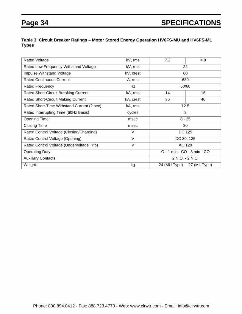
Table 3 Circuit Breaker Ratings – Motor Stored Energy Operation HV6FS-MU and HV6FS-MLTypes
Rated Voltage kV, rms 7.2 4.8Rated Low Frequency Withstand Voltage kV, rms 22Impulse Withstand Voltage kV, crest 60Rated Continuous Current A, rms 630Rated Frequency Hz 50/60Rated Short-Circuit Breaking Current kA, rms 14 16Rated Short-Circuit Making Current kA, crest 35 40Rated Short-Time Withstand Current (2 sec) kA, rms 12.5Rated Interrupting Time (60Hz Basis) cycles 3Opening Time msec 8 - 25Closing Time msec 30Rated Control Voltage (Closing/Charging) V DC 125Rated Control Voltage (Opening) V DC 30, 125Rated Control Voltage (Undervoltage Trip) V AC 120Operating Duty O - 1 min - CO - 3 min - COAuxiliary Contacts 2 N.O. - 2 N.C.Weight kg 24 (MU Type) 27 (ML Type)
Phone: 800.894.0412 - Fax: 888.723.4773 - Web: www.clrwtr.com - Email: [email protected]

WARRANTY AND LIMITATION OF LIABILITY Page 35
Toshiba International Corporation ("Company") warrants that all equipment and parts described herein will be freefrom defects in materials and workmanship. THIS WARRANTY WILL EXPIRE EIGHTEEN (18) MONTHS AFTERTHE DATE ON WHICH SUCH EQUIPMENT AND PARTS (EXCLUDING REPAIRED OR REPLACEMENTEQUIPMENT AND PARTS FURNISHED PURSUANT TO THIS WARRANTY) ARE SHIPPED BY THE COMPANYTO THE INITIAL PURCHASER OR TWELVE (12) MONTHS AFTER SUCH EQUIPMENT AND PARTS(EXCLUDING REPAIRED OR REPLACEMENT EQUIPMENT AND PARTS FURNISHED PURSUANT TO THISWARRANTY) ARE FIRST PLACED IN OPERATION, WHICHEVER PERIOD FIRST EXPIRES.
The Company will, at its option, repair or replace such equipment or part which is defective under the terms of theforegoing warranty, free of charge; provided the purchaser (1) promptly notifies the Company in writing of suchdefect, and (2) furnishes the Company satisfactory proof thereof, and (3) establishes that the equipment or part hasbeen properly installed, maintained and operated within the limits of rated capacity and normal usage and inaccordance with this manual, and (4) if requested by the Company, returns the defective equipment or part to theCompany and pays all expenses incurred in connection with such return. The repaired or replacement equipment orpart will be delivered, free of charge, to the purchaser F.O.B. the Company's warehouse or, at the Company's option,F.O.B. a Company authorized service shop, not loaded on truck or other carrier. The purchaser will pay the costsapplicable to the equipment or part following such delivery, including, without limitation, all handling, transportation,assembly, insurance, testing and inspection charges.
THE FOREGOING OBLIGATION TO REPAIR OR REPLACE EQUIPMENT PARTS SHALL BE THE SOLE ANDEXCLUSIVE REMEDY OF THE PURCHASER, ITS CUSTOMERS AND USERS OF THE EQUIPMENT ANDPARTS FOR BREACH OF THE FOREGOING WARRANTY. THE COMPANY WILL HAVE NO OBLIGATIONS TODISASSEMBLE ANY EQUIPMENT OR PART WHICH IS DEFECTIVE WITHIN THE TERMS OF THE ABOVEWARRANTY OR TO INSTALL ANY REPAIRED OR REPLACEMENT PART OR EQUIPMENT OR TO PAY ANYCOSTS INCURRED IN CONNECTION WITH ANY SUCH DISASSEMBLY OR INSTALLATION. THE COMPANY,TOSHIBA CORPORATION AND THEIR SUPPLIERS AND SUBCONTRACTORS HEREBY DISCLAIM ALLOTHER EXPRESS, STATUTORY AND IMPLIED WARRANTIES, INCLUDING, WITHOUT LIMITATION, ALLEQUIPMENT AND PARTS FURNISHED PURSUANT TO THE FOREGOING WARRANTY AND ALL IMPLIEDWARRANTIES OF MERCHANTABILITY.
The total liability of the Company, Toshiba Corporation and their suppliers and subcontractors for any loss, damageor claim, whether in contact, tort (including negligence and liability without fault), or otherwise, arising out of,connected with or resulting from the equipment and parts described in this manual or the performance or breach ofany contract for the sale or supply of such equipment and parts, or from the design, manufacture, sale, delivery,resale, installation, technical direction or supervision of installation, inspection, testing, repair, replacement,operation, maintenance or use of any such equipment or part or any service relating thereto furnished by theCompany shall not in any event exceed the price allocable to the equipment, part or service which gives claim, lossor damage. In no event, whether as a breach of contract or warranty, alleged negligence, liability without fault, orotherwise, shall the Company, Toshiba Corporation or their suppliers or subcontractors be liable for special orconsequential damages, including, without limitation, loss or profits or revenue, loss of equipment described hereinor any associated equipment, cost of capital, cost of substitute equipment or parts, facilities or services, down-timecosts, labor costs or claims of customers of the purchaser for such damages.
Phone: 800.894.0412 - Fax: 888.723.4773 - Web: www.clrwtr.com - Email: [email protected]