torus model containing a sliding well-mixed nsteady...
TRANSCRIPT
. Eng. Comm., 192305-826, 2005 right 8 Taylor & Francis Inc. : 0098-6445 printl1563-5201 online 10.1080/009864490521499
Torus Model Containing a Sliding Well-Mixed
nsteady Stirring Conditions in Agitated Vessels
J.-Y. DIEULOT Laboratoire d'Automatique et Informatique Industrielle de Lille, UMR CNRS 8021, Ecole Polytechnique Universitaire de Lille, Villeneuve d'Ascq, France
N. PETIT AND P. ROUCHON Centre Automatique et Systkmes, ~ c o l e des Mines de Paris, Paris, France
G. DELAPLACE
Institut National de la Recherche Agronomique, Laboratory for Food Process Engineering and Technology, Villeneuve d'Ascq, France
This article investigates the modeling of mixing phenomena occur at unsteady stir- ring conditions in that agitated vessels. In particular, a new model of a torus reactor including a well-mixed zone and a transport zone is proposed The originality of the arrangement of ideal reactors developed here is due to the time-dependent location of the boundaries between the two zones. This concept is applied to a model of the posi- tive influence of unsteady stirring condition on a homogenization process; the model avoids mass balance discontinuity during the transitions from steady to unsteady stirring conditions.
To ascertain the reliability of the modelproposed, experimental runs with highly vis- cousfluiak have been carried out in an agitated tank. The impeller used is a nonstandard helical ribbon impeller, fitted with an anchor at the bottom. The degree of hon~ogeneity in the tank is recorded using a conductivity method after a tracer injection.
It is shoivn that, for a given agitatedfluid and mixing system, the parameters of the model are easy to estimate and that modeling results are in close agreement with experimental ones. Moreover, it appears that this model allows the easy derivation of the control law, which is a great advantage when optimizing the dynamics of a mixing process.
Keywords Mixing; Modeling; Nonlinear dynamics; Parameter identification; Unsteady stirring; Torus model
High-viscosity mixing operations in batch mode are commonly encountered in chemical and food industries. The purpose of these mixing applications, which are
Address correspondence to J.-Y. Dieulot, Laboratoire dlAutomatique et Infonnatique Industrielle de Lille. UMR CNRS 8021. I.A.A.L. Ecole Polvtechniaue Universitaire de Lille.

J.-Y. Dieulot et al.
both time and energy consuming, is often to achieve, adequate end-product quality. However, in spite of its present wide use, the optimization of batch mixing remains an important challenge for process engineers. Depending on whether the design of the mixing system is set or not, there are different possible ways to improve mixing.
The first one is to select, for a given mixing system, the geometrical parameters that optimize the overall homogenization efficiency. Over the past few decades, this approach has been widely covered in literature. In particular, the effects of the design of the agitator and of various geometrical parameters of the mixing equipment (wall clearance, shape of the bottom, bottom clearance, number of baffles, and so on) on the efficiency of the homogenization process when stirring under steady rotational speed have been investigated. For example, one may mention studies concerning the determination of power consumption and mixing times for mixing systems equipped with close-clearance impellers such as screw or helical ribbon agitators (Tatterson, 1994; Delaplace and Leuliet, 2000; Delaplace et al., 2000a), which are known to be the best suited to achieving mixing of highly viscous media.
The second way is to consider that, for a given mixing system, the ability of a flow to homogenize viscous products can be significantly enhanced with the help of unsteady time-varying stirring methods. This approach is based on the point of view that efficient mixing in the laminar regime is related to the amount of stretching and folding generated within the tank by the agitator (Ottino, 1989; De La Villeon et al., 1998). Indeed, generally, when stirring conditions are steady, the initially designated material of fluid will follow closed streamlines in the vessel and conse- quently the mixing efficiency will be rather poor since such regular flows will induce a linear evolution of intermaterial area with time (Niederkorn and Ottino, 1994). However, when a suitable perturbation is superimposed on the steady velocity field, reorientation flows will appear, fluid elements will no be longer trapped by closed steady streamlines, and they will be free to move throughout chaotic flow domains. This is because the rate of stretching is higher in these flow regions, and the inter- material area will grow faster (Niederkorn and Ottino, 1994), and higher average efficiency values will be obtained.
Although it has been shown (Ottino, 1989; Aref, 1984) over the past two decades that a time periodic velocity field applied to two-dimensional flows (pipe for example) mixes more efficiently than a steady flow, few attempts have been made to apply this approach to a batch reactor (3-D) in order to enhance the efficiency of an existing mixing device.
For example, there is a lack of systematic studies providing us with quantitative information about the conditions under which these chaotic flows are produced and their actual benefits for mixing efficiency. Consequently, the design of a sequence of flows that involves a reorientation of material elements (for instance, when periodic or co-reverse rotation of the impeller is performed) has not been clearly identified.
Another lack appears if we analyze pioneering works (Lamberto et al., 1996; Nomura et al., 1997; Yao et al., 1998) that use unsteady stirring approaches to enhance laminar mixing in batch reactors. Most of the reported examples of the improvement of three-dimensional batch mixing using unsteady rotational speed operating conditions deal with small-diameter agitators that are usually devoted to work in turbulent regimes and are not suited to batch mixing viscous fluids. In this case, the key consider- ation of their work was to show that periodic or co-reverse rotation of the impeller can prevent the formation of the isolated mixed regions (Metzner and Taylor, 1960) (segregated regions) occur in stirred tanks for Reynolds numbers values below 500.

--
A Torus Model for Unsteady Mixing
From this survey, it appears clear that there is a strong need for rational studies that quantify the efficiency of a stretching process for a given mixing system. The lack of comparative knowledge of flow mixing ability does not allow the design of optimal control that would minimize the energy or time expense required to achieve a given degree of homogeneity. At the present state of the art, it is completety hopeless to try to achieve such a flow classification since it requires-the entire velocity field in a stirred tank to be known and to be explicitly integrated in order to obtain the stretch- ing required. To sum up, experimental and numerical studies of the hydrodynamics in an agitated vessel have so far failed to provide any solutions. It is, therefore, essential to design a proper flow model for such mixing processes that incorporates significant features of partially chaotic phenomena and can be used to assess the combined effects of unsteady and steady stirring approaches on mixing efficiency.
This article is a contribution to this purpose. In this work, a model is proposed to describe batch mixing of highly viscous fluids within a vessel equipped with a heli- cal ribbon impeller at unsteady stirring conditions. The flow model is original since it is based on a torus volume composed of a plug flow and a well-mixed region with time-varying boundaries. Experimental mixing runs (for steady and unsteady stirring approaches) are used to ascertain validity and to compare the performance of this model with that of models found in literature. Note that the ultimate framework of this scientific program is to determine an optimal controller, i.e., the rotational speed profile that minimizes the mixing energy for a given mixing time. It has been chosen to discard models based on paritial differential equations for which control design might be very difficult to carry out.
Previous Literature on Flow Modeling in Batch Reactor
Many types of models can be used to characterize real flow within a'batch reactor. For steady stirring approaches, Khang and Levenspiel (1976) have first shown that an agitated vessel can be modeled by a network of ideal reactors. Khang and Levenspiel's network consists of a plug flow reactor in series with a single continuous stirred tank reactor (CSTR1) with total recycling, in which the fluid flows with a constant flow rate Q (Figure 1). Assuming that both the volumes of these two ideal reactors (Vp for the plug flow reactor and Vd for the well-mixed zone) are constant and that the flow rate Q that appears in the model is proportional to the rotational speed of the impeller N, it was possible by one experimental run (one tracer injection)
Well mixed zone
Figure 1. Recycle models proposed by Khang and Levenspiel (1976) for batch mixing.


A Torus Model for Unsteady Mixing
the CSTR2 in the previous study) to account for changes in mixing conditions on transition from steady to unsteady stirring approaches. On the contrary, an attempt was carried out to model the increase in mixing efficiency due to unsteady stirring conditions both by varying the relative position of ideal zones that composed the final model and by not modifying the time parameter of each volume of the ideal zones. This was achieved by using the juxtaposition of a plug flow zone and a well-mixed zone within a torus volume with time-varying boundaries. In the follow- ing section, we will give more details the basis of the model and mathematical expres- sions of the space-time parameters for the ideal reactors contained in the torus
Principle of the Torus Reactor Model
Consider a torus of fixed volume V divided into two ideal reactors (a stirred tank reactor of volume Vd and a plug flow zone of volume V , ',-T V - Vd) in which flows a Newtonian fluid with a uniform time-varying flow rate Q in a clockwise direction (Figure 3). In the figure y(t) refers to the fluid concentration ( ~ ~ / m ~ ) in component y (tracer), which varies with time and space. It is assumed that the total material quantity of component y in the reactor remains constant.
The originally of the torus reactor arises from the time-dependent position of the boundaries (S1 and S2) that separate the two ideal flow zones. Indeed, it is assumed that when flow rate is non-steady, the relative position of the two ideal reactors is time varying. S1 and S2 move simultaneously with the same linear velocity and direction. Consequently, the relative volume of the two ideal reactors (Vd and vp)
Direction of rile sliding motion
I
Figure 3. Sketch of torus model proposed in this study. The intensity of gray represents the concentration in then torus. S l , S2: time-dependent boundaries of the two compartments mov- ing in counterclockwise direction; Q: fluid flow rate in the tank, moving in clockwise direction; Vd: constant volume of the well-mixed zone for the torus volume; Vn: constant volume of the plug-flow zone for the torus volume; y( t ) : tracer concentration in the well-mixed zone; 0: time-varying delay due to plug-flow transport.
: 810 J.-Y: Dieulot et A
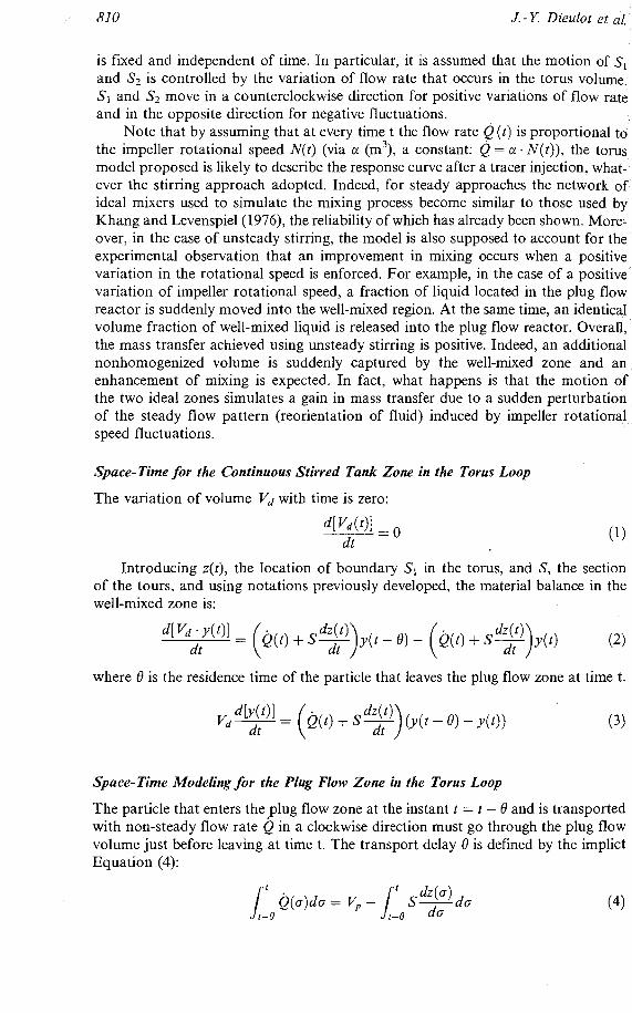
is fixed and independent of time. In particular, it is assumed that the motion of S , I and S2 is controlled by the variation of flow rate that occurs in the torus volum c S1 and S2 move in a counterclockwise direction for positive variations of flow ra t and in the opposite direction for negative fluctuations.
Note that by assuming that at every time t the flow rate Q ( t ) is proportional t 1
ever the stirring approach adopted. Indeed, for steady approaches the network t
ideal mixers used to simulate the mixing Drocess become similar to those used . ". 43, s:; ske' Khang and Levenspiel (1976), the reliability of which has already been shown. M
@: over, in the case of unsteady stirring, the model is also supposed to account for s: e4 J*
experimental observation that an improvement in mixing occurs when a positive 6 variation in the rotational meed is enforced. For exam~le. in the case of a ~osit iv
& volume fraction of well-mixed liquid is released into the plug flow reactor. Overall, the mass transfer achieved using unsteady stirring is positive. Indeed, an additional nonhomogenized volume is suddenly captured by the well-mixed zone and an enhancement of mixing is expected. In fact, what happens is that the motion the two ideal zones simulates a gain in mass transfer due to a sudden uerturbati of the steady flow pattern (reorientation of fluid) induced by impeller rotation sneed fli~ctuations~
Space-Time for the Continuous Stirred Tank Zone in the Torus Loop
The variation of volume Vd with time is zero:
d[Vd(t)l ----- = 0 dt (1)
Introducing z(t), the location of boundary S1 in the torus, and S, the section of the tours, and using notations previously developed, the material balance in the well-mixed zone is:
g Pi
d[Vd - Y ( ~ ) ] = (act) + S y ) y ( t ) g dt
(2)
C p$ where 8 is the residence time of the particle that leaves the plug flow zone at time t.
1 *Q
& vd- dlv(')] dt = ( ~ ( t ) + s%) dt ( ~ ( t - 8 ) - ~ ( t ) ) (3) %! g>; g , >.. p d Space-Time Modeling for the Plug Flow Zone in the Torus Loop F!
The particle that enters the plug flow zone at the instant t = t - 8 and is transported with non-steady flow rate Q in a clockwise direction must go through the plug flow volume just before leaving at time t. The transport delay 8 is defined by the implict

A Torus Model for Unsteady Mixing
Due to the clockwise direction of flow, the plug flow volume ahead of the particle can only decrease during the route. This decrease corresponds to the second right- hand term of Equation (4).
Matevial Balance in the Tovus Reactor
Theorem. The mass balance in the species y(t) within the torus reactor defined by Equations (3)-(4) is respected.
Proof: At time t , the quantity A ( t ) of the species y inside the reactor is the sum of that in the plug flow and the well-mixed zones,
where B(x, 2) is the time of residence of a particle whose abscissa in the plug flow zone is x (ranging from 0 to V p / S ) . The particles at position x at time t have entered the plug flow zone at time t - B(x , t ) . These particles had to travel the distance x - dz(ci), which yields the following relation that generalizes
Now let us show that the derivative of A ( t ) is zero. Deriving the equation above with respect to t and z, we obtain the useful
First, we calculate
which becomes, using previous equations,

and, integrating the last equation,
Replacing in the derivative of A ( [ ) yields:
which completes the proof.
Simulation ACgorithm Used for the Torus Reactor
Finally, using the notations previously introduced, the whole system can be charac- terized by the following differential equations:
Assuming that the total volume of torus reactor V corresponds to the volume of the fluid agitated, the proposed system involves four unknown parameters: '% V d , ~ ( t ) , and ~ ( t ) .
Providing two prerequisites, a simulation algorithm can be used to predict the
The two constant parameters (a and Vd), which are not influenced by the time- dependent rotational speed, are known. The effects of stirring conditions N ( t ) on boundary motions (S1 and S2) are estab- lished. Indeed, such knowledge will allow us to obtain z ( t ) at each instant time. Consequently, B(t) and then y ( t ) can also be computers.
The assumptions used in this article concerning the evolution of z ( t ) with stirring conditions are the following:
The simulation of a system involving an input-dependent transport delay is not always trivial since the delay is defined by an implict equation. In particular, Zenger and Ylien (1994) have shown that for most flow rate fluctuations, the expression of

A Torus Model for Unsteady Ilii-~ing
B ( t ) cannot be obtained analytically but must be computed by numerical methods. In this work, this issue is not dealt with in detail for the sake of simplicity. More infor- mation about the computational methods used in this work can be found in the orig- inal publication (Zenger and Ylinen, 1994) or a previous one (Dieulot et al., 2002).
Finally, note that the simulation algorithm has been developed considering the toroidal model as a discrete automaton. First, the torus has been divided into a large number of cells. At every simulation step, the values of the concentration should move from one cell of the plug flow zone to the next one, using the definition of a plug flow reactor (pure transport). The concentration in the well-mixed zone can then be computed using a total mass balance and the fact that the concentrations in every cell of the zone are equal. The boundaries are then updated. The time step is variable and corresponds to the residence time in a cell, which depends on the flow rate values (rotational speed).
Material and Methods
Apparatus Used to Monitov Mixing Expeviments
The mixing equipment used appears in Figure 4. During all the experiments, the level of the liquid at rest was kept constant at a 0.402m height for a total volume of 3 0 . ~ 0 - ~ rn3. Experiments were carried out with the helix pumping upward (counter- clockwise rotation). Additional information about the flow pattern produced by the mixing system is given elsewhere (Delaplace et al., 1999, 2000a,b).
The agitated fluid is an aqueous solution of glucose with a viscosity of 1.8 Pa.s at 26°C. A controlled speed rotational viscometer (Contraves, Rheomat 30) was used to determine the Newtonian viscosity of the medium. The shear rate ranged from 0 1.
t Figure 4. Photo and geometrical parameter of the mixing equipment investigated (other geo- metrical parameters of PARAVISC'~ mixing system: blade width, w = 0.032m; impeller pitch, p = 0.560 m; impeller height; L = 0.340m; tank height, H, = 0.443111).

A Torus Model for Unsteady Mixing 815
when mixing at constant impeller rotational speed (Figure 5). When the conductivity method was used, it is clear that the values of circulation and mixing times depended significantly on the location of the injection point and measurement probe. Never- theless, for the experimental conditions tested, the local values of axial circulation times obtained are in close agreement with the global values obtained by following the movement of freely suspended particles. Moreover, global values of axial circulation times deduced from computational fluid dynamics (CFD) velocity field (Delaplace et al. 2000a, 2001) were also in close agreement with those obtained by the conductivity method.
The conductivity signals (axial circulation curves) were particularly noisy, owing to recording problems and high-frequency environmental noise (Figure 5) . Filtering consisted first in the elimination of scatters. Measuring points with a derivative higher than a threshold value (empirically five times the signal derivative standard deviation) were replaced by an average value of their neighbors. The sampling period was taken to be equal to one second. This choice is important for parameter identi- fication and has been already justified and discussed elsewhere (Delaplace et al.,
n time, the ie agitation onductivity vated three ~perimental
ng and cir- racer injec- reach 95% nal period
Operating Stirring Conditions Tested
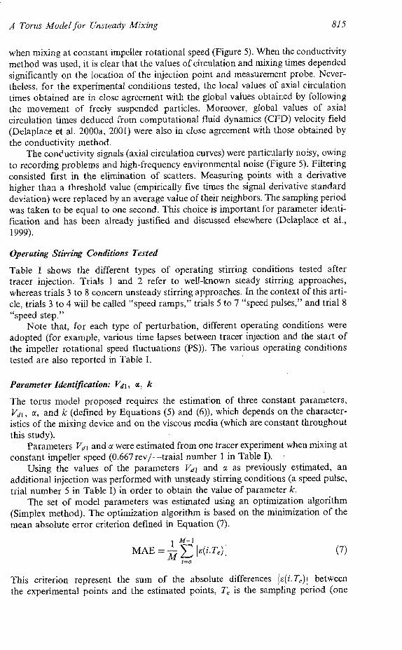
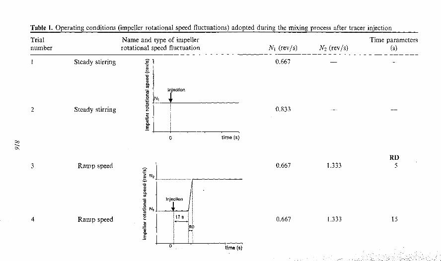
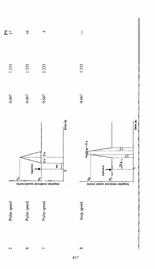
Table I shows the different types of operating stirring conditions tested after tracer injection. Trials 1 and 2 refer to well-known steady stirring approaches, whereas trials 3 to 8 concern unsteady stirring approaches. In the context of this arti- cle, trials 3 to 4 will be called "speed ramps," trials 5 to 7 "speed pulses," and trial 8 "speed step."
Note that, for each type of perturbation, different operating conditions were adopted (for example, various time lapses between tracer injection and the start of the impeller rotational speed fluctuations (PS)). The various operating conditions tested are also reported in Table I.
Parameter identification: V d l , N, k
The torus model proposed requires the estimation of three constant parameters, Vdl, a, and k (defined by Equations (5) and (6)), which depends on the character- istics of the mixing device and on the viscous media (which are constant throughout this study).
Parameters Vdk and ol were estimated from one tracer experiment when mixing at constant impeller speed (0.667 rev/-traial number 1 in Table I). ,
Using the values of the parameters Vdl and ol as previously estimated, an additional injection was performed with unsteady stirring conditions (a speed pulse, trial number 5 in Table I) in order to obtain the value of parameter k.
The set of model parameters was estimated using an optimization algorithm (Simplex method). The optimization algorithm is based on the minimization of the mean absolute error criterion defined in Equation (7).
M-1
MAE = - I E ( ~ . T , ) I i=o
This criterion represent the sum of the absolute differences Is(i.T,)I between the experimental points and the estimated points, T , is the sampling period (one
Steady stirring
Ramp speed
second), and M is the number of samples required to describe the homogen
Reliability of the Model
Using different operating conditions (trials 2-4 and 6-8 in Table 11) tha adopted for parameter estimation (trials I and 5), the validity of the mo
mixing times (obtained with the help of estimated parameters). The means abs error between experimental and model data was also computed and its compared to those obtained for the trials used for fitting.
Efficiency of Mixing Using Unsteady Stirring Conditions
The positive influence of unsteady stirring conditions on mixing efficiency is s
bations for homogenization processes.
Validity of the Model
The predictive model developed in this study was tested for our mixing equipment The well-mixed zone is supposed to account for the high-gradient zones, which
mainly lie within the gap between the helical impeller blade and the tank wall. On the other hand, the plug flow zone refers to the axial circulation motion of the fluid within the rest of the vessel. Of course, the sum of the plug flow and the well-mixed zone volumes is equal to the total volume of the vessel.
As mentioned before, one trial at constant impeller speed (trial 1) and one run at unsteady speed (a pulse, trial 5; see Table 111 were necessary to determine the set of parameters of the various ideal zones. The values of the parameters estimated (sup- posing that the surface of a section of the torus is lo-' m2) are: Vdl = 6.010-~ m3, a = 1.61 m3, and k = 0.37 m.s and were then used with other stirring conditions (see Table 111) to validate the proposed model.
Examples of curve fitting obtained by this approach are given in Figures 6-1 1. These figures show that the estimated response curve after tracer injection is close to the experimental one despite the high noise observed for the experimental curves and the nonlinearities (such as nonperiodicity of signals, which sometimes occurs at constant impeller speeds). Moreover, in order to test the accuracy of the model, the values of measured mixing times and values calculated by the model are reported in Table 111. we can note that there is close agreement between the experimental and predicted values of mixing times, whatever the stirring conditions adopted (mean error 9.2%). As previously explained, another criterion has also been computed to

.1 and mean :ed to


OUTPUT SIGNAL
I -.
0 -- - --
OUTPUT SIGNAL
---
A Torus Model for Unsteady Mixing
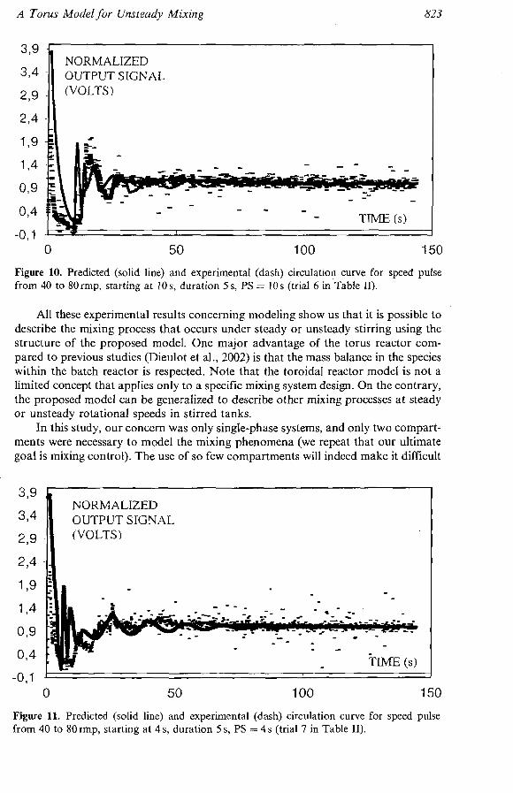
Figure 10. Predicted (solid line) and experimental (dash) circulation curve for speed pulse from 40 to 80rmp, starting at 10 s, duration 5 s, PS = 10s (trial 6 i n ~ a b l e 11).
All these experimental results concerning modeling show us that it is possible to describe the mixing process that occurs under steady or unsteady stirring using the structure of the proposed model. One major advantage of the torus reactor com- pared to previous studies (Dieulot et al., 2002) is that the mass balance in the species within the batch reactor is respected. Note that the toroidal reactor model is not a limited concept that applies only to a specific mixing system design. On the contrary, the proposed model can be generalized to describe other mixing processes at steady or unsteady rotational speeds in stirred tanks.
In this study, our concern was only single-phase systems, and only two compart- ments were necessary to model the mixing phenomena (we repeat that our ultimate goal is mixing control). The use of so few compartments will indeed make it difficult
, Figure 11. Predicted (solid line) and exper~mental (dash) circulation curve for speed pulse from 40 to 80 mp, starting at 4 s, duration 5 s, PS = 4 s (trial 7 in Table 11).

to use in multiphase mixing, such as with gas-liquid bioreactors. In this case, a m involving a network-of-zones with a large number of compartments is needed to ture the partial segregation of gas and. liquid phase reagents (Rahimi and M 2001; Zahradnik et al., 2001; Hristov et al., 2001) and related works.
the dynamics of mixing. Indeed, introducing the following change of time scale:
ds = ( ~ ( t ) + i / , f )dt
Equations (5) and (6) become:
where Q = U(s ( t ) ) ; y ( t ) = Y ( s ( t ) ) and s are defined by s = V,(U(s - s ) ) . From Equations (8) and (9), it can be seen that, if Vd is an increasing function of
u, then there is a difference when u > O(Tidf # 0) and u < O(l idf = O), and that for u > 0 the new "time" s ( t ) passes faster. Mixing is thus more efficient when the flow accelerates, which is consistent with experimental observations. This can be illu- strated by considering a flow with a sawtooth profile, for which the volumes will retain their initial value after the sawtooth is completed. In a first instance, the boundary S , moves and Vd expands. When S2 moves in turn and V, expands as u decreases, the plug flow zone will move counterclockwise and will overlap an area that was previously in the well-mixed zone. The effect of u < 0 is thus more limited than in the case where u > 0.
Finally, defining < by W = V d ( U ) as the control parameter and using volume balance in the torus, it can be written:
By construction W E [0, V ] and a positive solution for s always exists when W is a continuous function of s. When the equation has several roots, s should be chosen as the smallest. Consequently, using the torus model, an optimal solution for the control should be quite simple to obtain using algebraic methods. This will be tackled in future work.
Conclusion
A torus model has been developed to describe the mixing process at unsteady rotational speeds. The combination of ideal reactors proposed includes a well-mixed and a plug flow zone contained in a torus volume. The boundaries between the two zones vary with the flow rate (proportional to impeller rotational speed) and are sup- posed to represent the enhancement of mixing efficiency that is experimentally observed when using unsteady stirring conditions.
The knowledge of only three constant parameters, Vdl, a, and k , is required for the model proposed. Moreover, only two trials are necessary to estim'ate the three fixed parameters (one at constant impeller speed for Vdl and a, and one at unsteady rotational speed for k).
A Torus Model for Unsteady Mixing
Finally, the model proposed gives close agreement between predicted and experi- mental circulation curves and allows us to estimate the mixing times for any kind of rotational impeller speed profile. I t has been shown that the mathematical equations of the model will allow a control law for the rotational speed of the impeller to be determined.
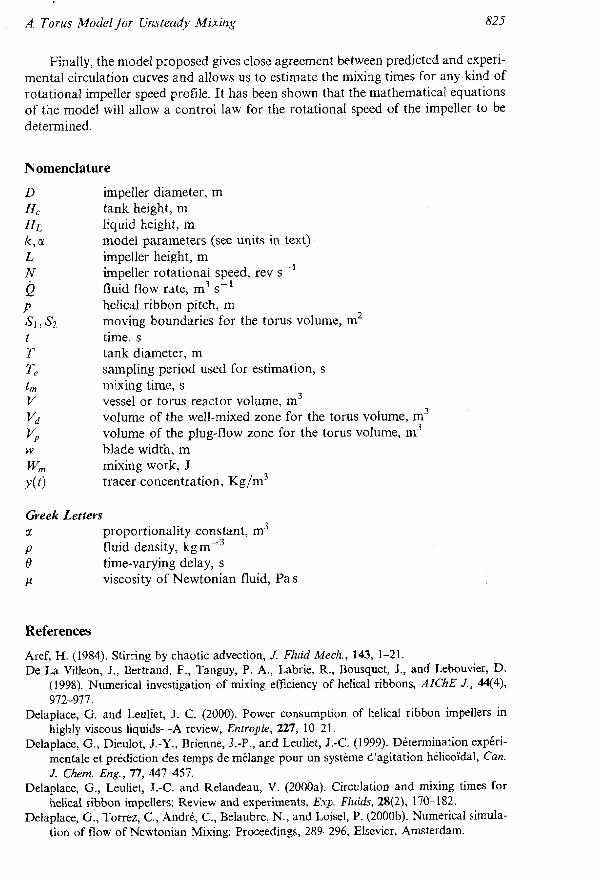
Nomenclature
impeller diameter, m tank height, m liquid height, m model parameters (see units in text) impeller height, m impeller rotational speed, rev s-' fluid flow rate, m3 s-' helical ribbon pitch, m
tank diameter, m sampling period used for estimation, s mixing time, s vessel or torus reactor volume, m3 volume of the well-mixed zone for the torus volume, m3 volume of the plug-flow zone for the torus volume, m3 blade width, m mixing work, J tracer concentration, ~ ~ / m ~
Gveek Letters proportionality constant, m3 fluid density, kg m-3 time-varying delay, s viscosity of Newtonian fluid, Pas
References
Aref, H. (1984). Stirring by chaotic advection, J. Fluid Mech., 143, 1-21. De La Villeon, J., Bertrand, F., Tanguy, P. A,, Labrie, R., Bousquet, J., and Lebouvier, D.
(1998). Numerical investigation of mixing efficiency of helical ribbons, AZChE J., w4), 972-977.
Delaplace, G . and Leuliet, J. C. (2000). Power consumption of helical ribbon impellers in highly viscous liquids-A review, Entropie, 227, 10-21.
Delaplace, G., Dieulot, J.-Y., Brienne, J.-P., and Leuliet, J.-C. (1999). Determination expkri- mentale et prediction des temps de melange pour un systeme d'agitation helico'idal, Can. J. Chem. Eng., 77, 447-457.
Delaplace, G., Leuliet, J.-C. and Relandeau, V. (2000a). Circulation and mixing times for helical ribbon impellers: Review and experiments, Exp. Fluids, 28(2), 170-182.
Delaplace, G., Torrez, C., Andre, C., Belaubre, N., and Loisel, P. (2000b). Numerical simula- tion of flow of Newtonian Mixing: Proceedings, 289-296, Elsevier, Amsterdam.

J. - Y. Dieulot el a
Delaplace, G., Torrez, C., Andre, C., and Leuliet, J.-C. (i001j. Tracer experiments, a way validate computational fluid dynamic simulations inan agitated vessel, Re'cents Progr en Ge'nie des Proce'dis, 15(79): 77-84.
Dieulot, J.-Y., Delaplace, G., Guerin, R., Brienne, J-P., and Leuliet, J. C. (2002). L mixing performances of a stirred tank equipped with helical ribbon agitator su to steady and unsteady rotational speed, TransIChemE, 80, Part A, 335-344.
Hristov, H., Mann, R., Lossev, V., Vlaev, S. D., and Seichter, P. (2001). A 3-D analysis of gas-liquid mixing, mass transfer and bioreaction in a stirred bio-reactor, Food Bioprod Process., 79, 232-24 1.
Khang, S. J. and Levenspiel, 0 . (1976). New scale-up and design method for stirrer agitated batch mixing vessels, Chem. Eng. Sci., 31, 569-577.
Lamberto, D. J., Muzzio, F. J., Swanson, P. D., and Tonkovich, A. L. (1996). Using time- dependent RPM to enhance mixing in stirred vessels, Chem. Eng. Sci., 51(5), 733-741.
Metzner, A. B. and Taylor, J. S. (1960). Flow patterns in agitated vessels, AIChE J., 6(1), 109-1 14.
Niederkorn, T. C. and Ottino, J. M. (1994). Chaotic mixing of shear-thinning fluids, AIChE J., 40(1 l), 1782-1793.
Nomura, T., Uchida, T., and Takahashi, K. (1997). Enhancement of mixing by unsteady agitation of an impeller in an agitated vessel, J. Chem. Eng. Jpn, 30(5), 875-879.
Ottino, J. M. (1989). The Kinematics of Mixing: Stretching, Chaos and Transport. Cambridge University Press, Cambridge.
Rahimi, M. and Mann, R. (2001). Macro-mixing, partial segregation and 3-D selectivity yields inside a semi-batch stirred reactor, Chem. Eng. Sci., 56, 763-769.
Tatterson, G. B. (1994). Scale Up and Design of Industrial Mixing Processes. McGraw-Hill, New York.
Yao, W. G., Sato, H., Takahashi, K., and Koyama, K. (1998). Mixing performance experi- ments in impeller stirred tanks subjected to unsteady rotational speeds, Chem. Eng. Sci., 53(17), 303 1-3043.
Zahradnik, J., Mann, R., Fialova, M., Vlaev, D., Vlaev, S. D., Lossev, V., and Seichter, P. (2001). A networks-of-zones analysis of mixing and mass transfer in three industrial bioreactors, Chem. Eng. Sci., 56, 485-492.
anger , K. and Ylinen, R. (1994). Simulation of variable delays in material transport models, Math. Comp. Simul., 37, 57-72.