torsional stiffening of wind turbine blades mitigating ... · torsional stiffening of wind turbine...
TRANSCRIPT
1
EUDP-LEX Project – Technical description
Torsional Stiffening of Wind Turbine Blades – Mitigating
leading edge damages
Project period: July, 2013 to June 2016
Supported by the EUDP-program – Project 64013-0115
Project prepared by the Partners under coordination of Bladena
Project manager: Find Mølholt Jensen, [email protected]. +45 53700276
Partners:
Bladena, Vattenfall, E.ON, Dong Energy, RWE, Total Wind Blades, RopePartner, DEWI, Aeroblade,,
ECC, DIS Engineering, Kirt-Thomsen, Boving Horn, Braendler, AAU Civil Engineering , DTU Wind
Energy, DTU Mechanical Engineering.

2
Contents
Executive technical summery ............................................................................................................................................. 5
Leading edge damages ....................................................................................................................................................... 6
Organization ...................................................................................................................................................................... 10
Output and deliverables ................................................................................................................................................... 10
WP0 Project management ................................................................................................................................................ 11
Task 0.1 – Start-up of project ....................................................................................................................................... 11
Task 0.2 – Kick-off seminar ........................................................................................................................................... 11
Task 0.3 – Project Management ................................................................................................................................... 11
Task 0.4 – Closing and final reporting to EUDP ............................................................................................................. 11
Task 0.5 – Project Communication ............................................................................................................................... 11
WP1 Development of a new Standardization process ...................................................................................................... 12
Task 1.1 – Status Standardization procedure................................................................................................................ 12
Task 1.2 – Proposal for future Standardization procedure ........................................................................................... 12
WP2 Damage assessment and measurement techniques ................................................................................................ 12
Task 2.1 - Structural assessment of reference blade .................................................................................................... 12
Task 2.2 – Instrumentation for measurement of operational response ....................................................................... 13
Task 2.3 – AE-system on Sub-component and full-scale test ........................................................................................ 13
WP3 Field measurement and testing ................................................................................................................................ 15
Task 3.1 – Reference Field Measurement of Project Turbine ....................................................................................... 15
Task 3.2 – As-is Field Measurement of Project Turbine ................................................................................................ 15
Task 3.3 – Demonstration Test of Retrofit Stiffener Solution ....................................................................................... 15
Task 3.4 – Demonstration Test of Retrofit Damping Solution ....................................................................................... 16
WP4 Full-scale fatigue testing ........................................................................................................................................... 16
Task 4.1 – Load envelope. – Responsible: DTU Wind Energy .................................... Fejl! Bogmærke er ikke defineret.
Task 4.2 - Field Test Procedures and program - Responsible: DTU Wind Energy ....... Fejl! Bogmærke er ikke defineret.
Task 4.3 - Full Scale Test Procedures and program – Responsible: DTU Wind Energy Fejl! Bogmærke er ikke defineret.
Task 4.4 - Full Scale Test Procedures and program for Retrofit Damping – Responsible: Blaest Fejl! Bogmærke er ikke
defineret.
Task 4.5 - Full Scale Test – As is – Responsible: Blaest........................................... Fejl! Bogmærke er ikke defineret.
Task 4.6 - Full Scale Test - With Retrofit Stiffener Solution – Responsible: Blaest ..... Fejl! Bogmærke er ikke defineret.
Task 4.7 - Full Scale Test - With Retrofit Damping Solution ....................................... Fejl! Bogmærke er ikke defineret.
WP5 Sub-component and sub-structure fatigue testing .................................................................................................. 17
Task 5.1: Sub-component testing of anchoring details ................................................................................................. 17
Task 5.2: Sub-structure test rig and plan for retrofit stiffener/damping solution ........................................................ 18
Task 5.3: Fatigue testing of retrofit stiffener solution .................................................................................................. 18
Task 5.4: Fatigue testing of retrofit damping solution .................................................................................................. 18
WP6 Finite Element Simulation ........................................................................................................................................ 19
Task 6.1: Development of FE models ............................................................................................................................ 19
Task 6.2: Validation and calibration of models against test results .............................................................................. 19
Task 6.3: Extract cross section data .............................................................................................................................. 19
Task 6.4: Study the effect of combined load cases ....................................................................................................... 20
Task 6.5: Study the influence of blade length ............................................................................................................... 20
Task 6.6: Simulation of Retrofit Stiffener Solution ....................................................................................................... 20
Task 6.7: Optimization Study for retrofit stiffener in Project Turbine ........................................................................... 20

3
Task 6.8: Simulation of New Design Stiffener Solution ................................................................................................. 20
Task 6.9: Simulation of Retrofit Damping Concept of project turbine.......................................................................... 20
Task 6.10: Simulation of Retrofit Damping Solution ..................................................................................................... 20
WP7 Design Tools for Wind Turbine Blades ...................................................................................................................... 21
Task 7.1: Extended Beam Theory ................................................................................................................................. 22
Task 7.2: Program documentation ............................................................................................................................... 22
Task 7.3: Comparative Design Studies .......................................................................................................................... 22
Task 7.4: Inclusion of dynamic effects primarily from damping elements ................................................................... 22
Task 7.5: Non-linear effects (Brazier effect) ................................................................................................................. 23
Task 7.6: Update of Design Guidelines for Wind Turbine Blades ................................................................................. 23
WP8 Detailed blade modelling implemented in aero-elastic analyses ............................................................................. 24
Task 8.1: Generate super-element ............................................................................................................................... 24
Task 8.2: Import super-element into HAWC2. .............................................................................................................. 24
Task 8.3: Investigate results in full FE-model ................................................................................................................ 24
Task 8.4: New solutions ................................................................................................................................................ 24
Task 8.5: Load simulation ............................................................................................................................................. 25
WP9 Product development ............................................................................................................................................... 25
Task 9.1 – First Product Concept for Retrofit Stiffener ................................................................................................. 25
Task 9.2 – Product Concept for Retrofit Stiffener ......................................................................................................... 25
Task 9.3 – Establishment of FMEA model and Critical Assumptions ............................................................................ 25
Task 9.4 – Development of Retrofit Solution with alternatives .................................................................................... 26
Task 9.5 – Comparative Analysis of Alternative Solutions ............................................................................................ 26
Task 9.6 – Design FMEA for Retrofit Stiffener Solution ................................................................................................ 26
Task 9.7 – Full Concept Description of Retrofit Stiffener Solution ................................................................................ 26
Task 9.8 – Prototype of Retrofit Stiffener Solution ....................................................................................................... 26
Task 9.9 – Installation Guide for Retrofit Stiffener for Field Testing ............................................................................. 26
Task 9.10 – Pilot Project for Retrofit Stiffener Solution ................................................................................................ 26
Task 9.11 – Product Concept for New Design Stiffener Solution .................................................................................. 26
Task 9.12 – Full Concept Description of New Design Stiffener Solution ....................................................................... 26
Task 9.13 – Development of a license product for New Design Stiffener ..................................................................... 27
Task 9.14 – Upgrade Concept for Retrofit Stiffener to Retrofit Damping ..................................................................... 27
Task 9.15 – Full Description of the Retrofit Damping Solution ..................................................................................... 27
Task 9.16 – Update design FMEA to include Retrofit Damping Stiffener...................................................................... 27
Task 9.17 – Full Concept Description of Retrofit Damping Solution ............................................................................. 27
Task 9.18 – Prototype of Retrofit Stiffener Solution ..................................................................................................... 27
WP10 Marked Entrance Barriers....................................................................................................................................... 28
Task 10.1 – First review of first product concept for retrofit stiffener .......................................................................... 28
Task 10.2 – Identification and handling of market barriers for retrofit stiffener .......................................................... 28
Task 10.3 – Update of handling of Market Barriers for Retrofit Damping .................................................................... 29
Task 10.4 – Preparation of substantiated Cost-Benefit Model for the proposed products. ......................................... 29
WP11 Visualization and Logging ....................................................................................................................................... 30
Task 11.1: Development of Visualization Model to be used in project ........................................................................ 30
Task 11.2: Hypothesis Work Out................................................................................................................................... 30
Task 11.3: Verification Work Out .................................................................................................................................. 30
Task 11.4: Retrofit Stiffener Concept Work Out ........................................................................................................... 30
Task 11.5: Retrofit Stiffener Solution Work Out ........................................................................................................... 30
Task 11.6: Product Visualization - Retrofit and New Design Stiffening Solutions Work Out ........................................ 30
Task 11.7: Project Part Evaluation Work Out ................................................................................................................ 31

4
Task 11.8: Hypothesis Work Out – Aerodynamic Instability and Edge Wise vibration ................................................. 31
Task 11.9: Retrofit Damper Solution Work Out ............................................................................................................ 31
Task 11.10: Project Closing Work Out ........................................................................................................................... 31
Task 11.11: Development of Commercial Development Program visualisation/logging tool ...................................... 31
WP12 Design of a new blade ............................................................................................................................................ 32
Task 12.1: Design of Blade ......................................................................................... Fejl! Bogmærke er ikke defineret.
Task 12.2: Manufacture of Blade ............................................................................... Fejl! Bogmærke er ikke defineret.

5
Executive technical summery
Problem definition
Wind turbine blades are during operation exposed to high stresses which have shown after few years
of operation to result in damages, visible or not from the surface and including longitudinal cracks.
The high stresses in this region of the leading edge is due to (i) edgewise static forces due to gravity,
(ii) edgewise dynamic forces, (iii) flapwise forces due to the aerodynamic shape and (iv) an important
“torsional” component caused by coupling deformations from the flapwise bending of the blade, as
seen on Figure 1, below.
Figure 1 - Torsional load contribution caused coupling deformations from flapwise bending deflections
Graph showing the distribution of edgewise loading combining static, dynamic and aerodynamic loads
6
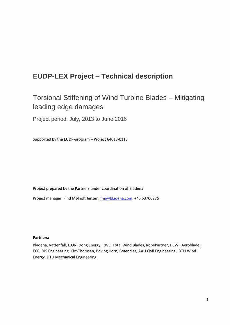
FEM simulations, full-scale and field testing all show deformation behavior of the cross-section in
shear as indicated in Figure 2, which could explain the multiple longitudinal cracks observed near the
leading edge for a wide spectrum of operational wind turbine blades of varying sizes. This type of
damage is a ofte found in blades in operation, indicating that this mode of failure is not sufficiently
taken into account in current state of-the-art turbine blade design methodology.
Figure 2 – Cross reinforcement reduce cross sectional shear deformation
Possible solution
Based on observations and hypothesis mentioned above, increased shear stiffness of the blade cross-
section is needed in order to mitigate the blade shear deformations thought to be the cause of
leading edge damages. One possible solution could be to insert a stiffener element in the shape of a
cross, (hence the name of “X-Stiffener”), as illustrated in Figure 2 above. Furthermore, a damper
element can be included on the X-Stiffener which would then reduce the edgewise vibration,
resulting in lower stress level in the leading edge area.
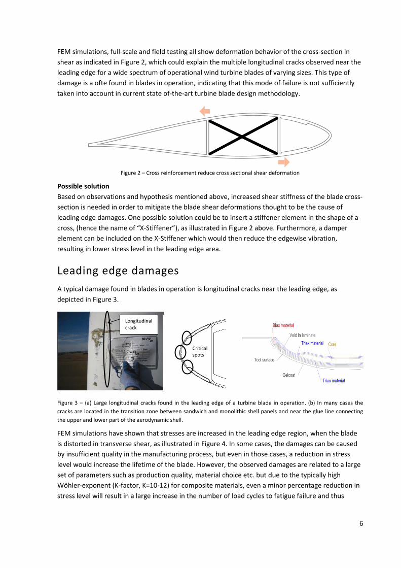
Leading edge damages
A typical damage found in blades in operation is longitudinal cracks near the leading edge, as
depicted in Figure 3.
Figure 3 – (a) Large longitudinal cracks found in the leading edge of a turbine blade in operation. (b) In many cases the
cracks are located in the transition zone between sandwich and monolithic shell panels and near the glue line connecting
the upper and lower part of the aerodynamic shell.
FEM simulations have shown that stresses are increased in the leading edge region, when the blade
is distorted in transverse shear, as illustrated in Figure 4. In some cases, the damages can be caused
by insufficient quality in the manufacturing process, but even in those cases, a reduction in stress
level would increase the lifetime of the blade. However, the observed damages are related to a large
set of parameters such as production quality, material choice etc. but due to the typically high
Wöhler-exponent (K-factor, K=10-12) for composite materials, even a minor percentage reduction in
stress level will result in a large increase in the number of load cycles to fatigue failure and thus
Longitudinal crack
Critical spots

7
structural lifetime, before leading edge damages will occur. An example: If the stresses are reduced
by 10% then the number of cycles to fatigue failure are increased by 100-120%, so if the blade has
crack issues after 5 years, then the blade can be expected to be extended 10-12 years when the X-
stiffener is retrofitted. There might be a larger reduction in stress level and therefore the problem is
solved for the remaining lifetime.
Figure 4 - Numerical simulation shows increased stresses in the leading edge region, when the blade is distorted in
transverse shear.
The cross-sectional shear distortion behavior has earlier been measured both in full-scale test at DTU
Wind Energy, see Figure 5, and in field test, as summarized in Figure 6.
Figure 5 – (a) Full-scale test performed at DTU Wind Energy, showed cross-sectional shear distortion. The blade is loaded at
a 30o angle to the flapwise direction, simulating combined flap- and edgewise loads.
Figure 6 - Results from a field test performed in an on-going EUDP-project. The measured cross-sectional shear distortion is
measured under normal operational loads around 8-10m/s.
In both the full-scale test and the field test, a clear cross-sectional shear distortion could be
measured. The results look different from Figure 5 and Figure 6, but are in fact showing the same
Increased stresses in
leading edge area
Displacement
sensors
measuring
cross-sectional
shear distortion
Graph showing cross-sectional shear distortion during operation
8
deformation behavior. In the full-scale test shown in from Figure 5 the load is static, while in the
field test shown in Figure 6, the loading is oscillating following a sinus curve following the rotation of
the rotor. Furthermore, the shear deformation will change in magnitude, when the gravity loads
direction change depending on the blade position. Both “torsional” and the flapwise load
components, shown in Figure 1, become more severe for long and more slender blades, but the
“torsional” load component has generally received less attention in blade design. It has however
been proven significant, especially for longer and more slender blades. The “torsional” load
component does not receive much attention either in the certification process. Testing for the
certification is performed with equipment which excites the blade at one of its Eigen frequencies.
The equipment does not readily allow for excitation of the Eigen frequencies for torsion and as the
test standards and certification rules do not demand torsional testing, therefore these kinds of tests
have often been omitted in the past.
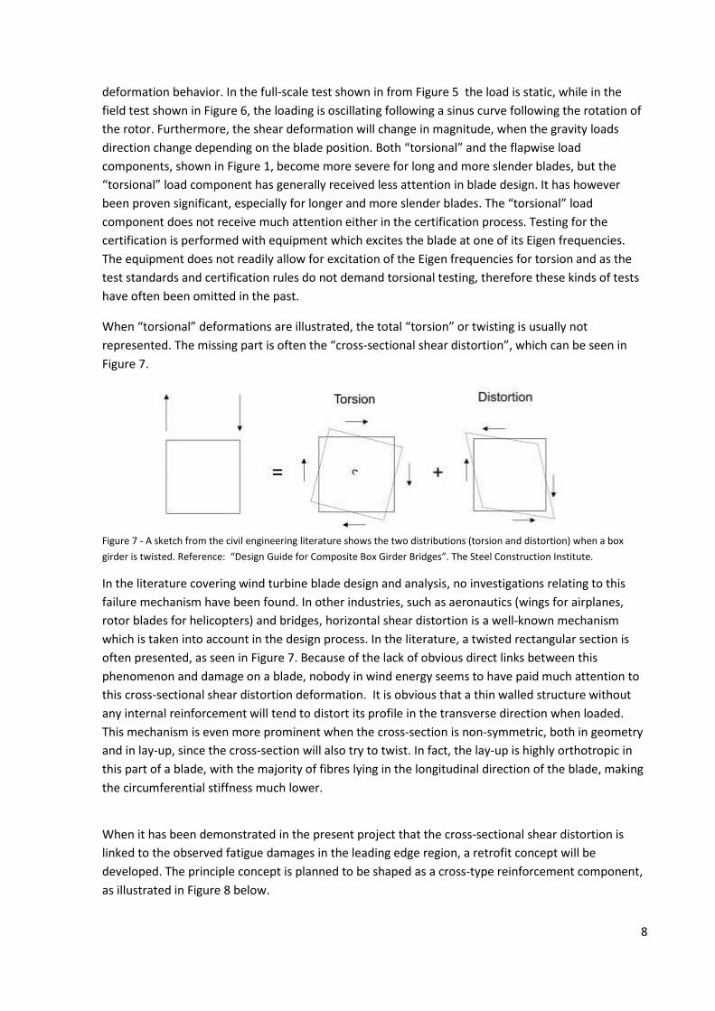
When “torsional” deformations are illustrated, the total “torsion” or twisting is usually not
represented. The missing part is often the “cross-sectional shear distortion”, which can be seen in
Figure 7.
Figure 7 - A sketch from the civil engineering literature shows the two distributions (torsion and distortion) when a box
girder is twisted. Reference: “Design Guide for Composite Box Girder Bridges”. The Steel Construction Institute.
In the literature covering wind turbine blade design and analysis, no investigations relating to this
failure mechanism have been found. In other industries, such as aeronautics (wings for airplanes,
rotor blades for helicopters) and bridges, horizontal shear distortion is a well-known mechanism
which is taken into account in the design process. In the literature, a twisted rectangular section is
often presented, as seen in Figure 7. Because of the lack of obvious direct links between this
phenomenon and damage on a blade, nobody in wind energy seems to have paid much attention to
this cross-sectional shear distortion deformation. It is obvious that a thin walled structure without
any internal reinforcement will tend to distort its profile in the transverse direction when loaded.
This mechanism is even more prominent when the cross-section is non-symmetric, both in geometry
and in lay-up, since the cross-section will also try to twist. In fact, the lay-up is highly orthotropic in
this part of a blade, with the majority of fibres lying in the longitudinal direction of the blade, making
the circumferential stiffness much lower.
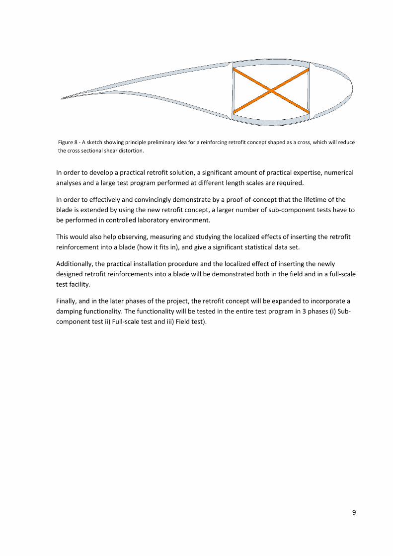
When it has been demonstrated in the present project that the cross-sectional shear distortion is
linked to the observed fatigue damages in the leading edge region, a retrofit concept will be
developed. The principle concept is planned to be shaped as a cross-type reinforcement component,
as illustrated in Figure 8 below.
9
Figure 8 - A sketch showing principle preliminary idea for a reinforcing retrofit concept shaped as a cross, which will reduce
the cross sectional shear distortion.
In order to develop a practical retrofit solution, a significant amount of practical expertise, numerical
analyses and a large test program performed at different length scales are required.
In order to effectively and convincingly demonstrate by a proof-of-concept that the lifetime of the
blade is extended by using the new retrofit concept, a larger number of sub-component tests have to
be performed in controlled laboratory environment.
This would also help observing, measuring and studying the localized effects of inserting the retrofit
reinforcement into a blade (how it fits in), and give a significant statistical data set.
Additionally, the practical installation procedure and the localized effect of inserting the newly
designed retrofit reinforcements into a blade will be demonstrated both in the field and in a full-scale
test facility.
Finally, and in the later phases of the project, the retrofit concept will be expanded to incorporate a
damping functionality. The functionality will be tested in the entire test program in 3 phases (i) Sub-
component test ii) Full-scale test and iii) Field test).

10
Organization
The project is organized in 13 work packages including a project management and a project duration of 3 years is planned. The work packages are as follows:
WP0 Project management – Find M. Jensen, Bladena
WP1 Development of a new Standardization process – John D. Sørensen, AAU Civil Engineering
WP2 Damage assessment and measurement techniques, Malcolm McGugan, DTU Wind Energy
WP3 Field measurement and testing – Johnny Plauborg, Total Wind Blades
WP4 Full-scale fatigue testing – Carsten Skamris, Blaest – WP is closed, activities moved to WP5 and
WP6
WP5 Sub-component and sub-structure fatigue testing, Christian Berggreen, DTU Mechanical
Engineering
WP6 Finite Element Simulation – Find M. Jensen, Bladena
WP7 Design Tools for Wind Turbine Blades – Lars Damkilde, AAU Civil Engineering
WP8 Detailed blade modelling implemented in aero-elastic analyses – Torben J. Larsen, DTU Wind
Energy
WP9 Product development – Laurids Egedal Kirchhoff, DIS-Engineering
WP10 Market Entrance Barriers – Søren H. Petersen, Boving Horn
WP11 Visualization and Logging – Rune Kirt, Kirt-ThomsenWP12 Design of a new blade – Pedro
Muñoz de Felipe, Aeroblade
Output and deliverables
The deliverables for each WP are organized in 3 levels for data analysis:
Deliverable at level 1: Raw data
Deliverable at level 2: Raw data analyzed
Deliverable at level 3: Analyzed data in a data report or similar
Deliverable can also be a PowerPoint presentation, arranging a workshop, a presentation, etc..
In the following description of each Work Package, each task will have a set of deliverables. The work
package leader is responsible for the timely submission of the deliverables.

11
WP0 Project management
Partners: Bladena, DTU Wind Energy, DTU Mechanical Engineering, AAU Civil Engineering, Vattenfall,
Total Wind Blades, RopePartner, Blaest, Kirt-Thomsen, ECC, Aeroblade, DEWI OCC, Boving Horn, DIS
Engineering, Braendler, RWE, E.ON, Dong Energy and BroadWind.
In this work package, the management of the project will be carried out. A steering committee will
be established consisting of one person from each partner. The progress of the project will be closely
followed and adjusted to the needs and demands of the partners ensuring that feed-back from
industrial partners will be taken into account and implemented during the entire project period.
Working groups will in the beginning of the project be set up e.g. a working group which discusses
how the retrofit reinforcement can be implemented in wind turbines.
Task 0.1 – Start-up of project Finalizing of all agreements, acceptance of grant and preparation of kick-off seminar.
Deliverable 0.1: Acceptance of Grant and invitation to kick-off seminar
Task 0.2 – Kick-off seminar Kick off seminar with all partners. Key actions points are to be prepared and the partners shall agree
on final project plan and communication plan.
Deliverable 0.2: Project and communication plans
Task 0.3 – Project Management Provide overall project management including reporting, follow up, coordinating, planning and
executing steering committee meetings administrate payments and generally manage the project to
ensure smooth and effective progress.
Deliverable 0.3: Project Management
Task 0.4 – Closing and final reporting to EUDP Closing of the project including the final audit and report.
Deliverable 0.4: Project report
Task 0.5 – Project Communication Executing the communication plan and support the project partners in their individual
communication both within the project and to external stake holders.
Deliverable 0.5: Continues and professional project communication.
Output: – Smooth delivery of the project, partner and EUDP satisfaction.

12
WP1 Development of a new Standardization process
Partners: AAU Civil Engineering, DEWI, AeroBlade, Vattenfall and Bladena.
In this work package the existing standardization procedure will be reviewed with focus on
recommendations / rules for avoiding leading edge cracks. A new standardization process will be
proposed focusing on leading edge cracks.
Task 1.1 – Status Standardization procedure An overview of the standardization on blades will be collected with particularly focus on addressing
the leading edge fatigue cracks.
Deliverable 1.1: Document which describe status of current standardization on blades with focus LE-
cracks.
Output: Input for improving the coming certification process
Task 1.2 – Proposal for future Standardization procedure A new standardization procedure has to be developed. The process must include a practical
approach which can be implemented as an add-on to the recent certification procedure.
Deliverable 1.2: Describe the standardization approach so future blades can avoid LE-cracks.
Output: Request which the Wind turbine owners should require in the future when they order new
blades.
WP2 Damage assessment and measurement techniques
Partners: DTU Wind Energy, Total Wind Blades, Bladena, Braendler and DTU Mechanical Engineering,
Vattenfall, E.ON, Dong Energy, RWE
This work package co-ordinates the application of various inspection and monitoring technologies to
provide adequate detail regarding the structural response and damage condition around the leading
edge panels during operation, during full-scale testing, and when undergoing dynamic fatigue sub-
component testing. This work package will also deliver a structural assessment of the wind turbine
blades and structural sections made available to the consortium for testing.
Task 2.1 - Structural assessment of reference blade This task includes the generation of a cutting plan for extraction of sub-component specimens,
structural assessment of the blade sections for testing (including a damage map) with annotated
images from the visual inspection, and where appropriate, the use of other non-destructive
technologies (such as ultrasonic inspection) to characterize sub-surface damages. This Work Package
can also supply non-destructive inspection of the bond line quality in sub-components for testing,
and an assessment of the damage condition prior to, during, and following dynamic testing.
Additionally, structural inspection of the blade sections before and after reinforcement and
instrumentation will document the condition of the structural material and the presence of any
damages.
Deliverable 2.1.a: Cutting plan. – Bladena, TotalWind Blades, DTU Mechnical

13
Deliverable 2.1.b: Structural assessment report. - DTU Wind Energy
Output: A structural assessment report and subsection suitable for testing in WP5.
Task 2.2 – Instrumentation for measurement of operational response This task includes agreement on and implementation of an instrumentation plan suitable for the
structural sections of interest in the operating wind turbines. All relevant measurement hardware
and attachment consumables will be assembled and tested within this task, including an appropriate
data acquisition system. The measurement suite can include displacement sensors, inclinometer,
strain gauges, accelerometers and fibre optic systems. The agreed instrumentation will be presented
to Total Wind Blades for installation in the blade, both for the reinforced and non-reinforced
condition.
Deliverable 2.2.a: Agreement on the measurement parameters of interest (local and global
deformations) – All.
Deliverable 2.2.b: All measurement and data acquisition hardware (+ installation consumables) –
DTU Wind Energy.
Deliverable 2.2.c: Instrumentation plan – DTU Wind Energy.
Deliverable 2.2.d: Data output, analysis and report – DTU Wind Energy.
Note that this task is linked to task 3.1 and some activities will overlap.
Output: Data report describing the instrumentation of both reinforced and un-reinforced sections of
the turbine blade and providing measurement analysis.
Task 2.3 – AE-system on Sub-component and full-scale test This task includes instrumentation of an Acoustic Emission (AE) system on the full-scale tests in WP5
and the sub-section test to be performed in Lyngby. The AE output will help to characterize the
response of the structure to dynamic loading by detecting (and localizing) the initiation and growth
of damage within the composite material and structural bondlines.
Deliverable 2.3.a: Instrumentation of full-scale blade prior to test in WP5. DTU Wind Energy
Deliverable 2.3.b: Instrumentation of sub-component test specimens in Lyngby. DTU Wind Energy
Deliverable 2.3.c: Data output, analysis and input to final test reports. - DTU Wind Energy
Task 2.4: Demonstration of Comprehensive ground based blade Inspection
This task includes the demonstration of a computerized ground based imaging system that captures
high resolution images across the entire surface of a blade, and then applies a consistent and
objective method of classifying blade defects, based upon the Guide2Defect criteria. The complete
blade coverage and location data on each defect allows comparison of the blade over time, and the
comparison across a blade fleet.
Deliverable 2.4.a: Onsite inspection of one wind turbine - Braendler

14
Deliverable 2.4.b: Full Defect assessment report (results provided with precise location, annotated
images, and overall blade/turbine condition) - Braendler
Deliverable 2.4.c: Defect assessment report with results provided in Guide2Defect format - Braendler
Output: A defect assessment report suitable for use in WP10.
Task 2.5: Demonstration of Fleet Management software
This task includes the demonstration of a computerized fleet management system that collates visual
and other information on turbines and displays the results in formats that assists in the development
of an appropriate site or fleet wide blade maintenance strategy.
Information displayed will include:
images captured from ground based inspection systems, rope access, and UAV.
Power curve information
Audio data
Deliverable 2.5.a: Data loaded into fleet management software - Responsible: DTU Wind Energy-
Braendler
Deliverable 2.5.b: Reports from fleet management system- Braendler
Output: A fleet management software partially preloaded with data suitable for use in WP10.

15
WP3 Field measurement and testing
Partners: Total Wind Blades, Bladena, Vattenfall, E.ON, Dong Energy, RWE, DTU Wind Energy,Rope
Partner and Broadwind.
This work package covers tests of a Vestas 2.0 MW wind turbine owned by Vattenfall. The full-scale
tests performed in this project will include comprehensive monitoring technology to measure local
and global deformation during operation. By using advanced measurement equipment, torsional and
bending deformation can be predicted in blades both with and without the X-cross retrofit
reinforcements.
Task 3.1 – Reference Field Measurement of Project Turbine Blade access at the onset of the project necessary to mount instrumentation to assess deformations
along the spar length, in order to get an initial set of distortion data edge panel displacement data.
Deliverable 3.1.a: Instrumentation plan Total Wind Blades.
Deliverable 3.1.b: Instruments delivered to Total Wind Blades from DTU Wind Energy ready to be
fitted, trial fit in blade on the ground/simulation.
Deliverable 3.1.c: Installation of equipment and data gathering by Total Wind Blades.
Deliverable 3.1.d: Raw data package supplied/transmitted to Spice Tech for analysis.
Deliverable 3.1.e: Data analysed by Spice Tech. (Sub-contractor to Total Wind Blades), and partners.
Deliverable 3.1.f: Data report submitted.
Output: Raw data package on displacements.
Task 3.2 – As-is Field Measurement of Project Turbine Blade access to mount Posiwires and load sensors alongside the spar length (inside the blade), in
order to confirm the distortion data along the length of the blade shown in task 3.1, and correlate
with load data measure in this task, between the root and up to radius 20.
Deliverable 3.2.a: Instrumentation plan to Total Wind Blades.
Deliverable 3.2.b: Instruments delivered to Total Wind Blades from DTU Wind Energy ready to be
fitted, trial fit in blade on the ground/simulation.
Deliverable 3.2.c: Installation of equipment and data gathering by Total Wind Blades.
Deliverable 3.2.d: Raw data package supplied to DTU Wind Energy for analysis.
Deliverable 3.2.e: Data analysed by DTU Wind.
Deliverable 3.2.f: Data report submitted.
Task 3.3 – Demonstration Test of Retrofit Stiffener Solution Deliverable 3.3.a: Instrumentation plan from to TWB.
Deliverable 3.3.b: Instruments delivered to TWB from DTU Wind Energy ready to be installed.
Deliverable 3.3.c: Retrofit reinforcements delivered to TWB from Bladena ready to be installed, trial
fit in blade on the ground/simulation.
Deliverable 3.3.d: Installation of equipment, retrofit reinforcements and data gathering by TWB.
Deliverable 3.3.e: Raw data package supplied to DTU Wind Energy and Spice Tech. for analysis.
16
Deliverable 3.3.f: Data analyzed by DTU Wind Energy and Spice Tech.
Deliverable 3.3.g: Data report submitted.
Task 3.4 – Demonstration Test of Retrofit Damping Solution Third blade access at the same time as installation of retrofit reinforcement with optimized sensor
position and optical measurement tools used in 3.1.
Deliverable 3.4.a: Instrumentation plan from to TWB.
Deliverable 3.4.b: Instruments delivered to TWB from DTU Wind Energy ready to be installed.
Deliverable 3.4.c: Retrofit reinforcements delivered to TWB from Bladena ready to be installed, trial
fit in blade on the ground/simulation.
Deliverable 3.4.d: Installation of equipment, retrofit reinforcements and data gathering by TWB.
Deliverable 3.4.e: Raw data package supplied to DTU Wind Energy and Spice Tech. for analysis.
Deliverable 3.4.f: Data analyzed by DTU Wind Energy and Spice Tech.
Deliverable 3.4.g: Data report submitted.
Task 3.5: Input to “Next Generation Inspection Reports” Inspection reports today is not optimized to the existing knowledge about of Root Causes and
therefore a new generation of inspection report need to be developed. In this process input from the
field is important
Deliverable 3.5: Description and photos to next generation
Task 3.6: Input to the LEX-Handbook Partners in the LEX-project are given input to the handbook explaining terms and definitions. Terms
and definitions used in the field will be explained by text and phothoes
Deliverable 3.6: Description and photos to the LEX-Handbook
Task 3.7: Extensive cutting program of samples Partners in the LEX-project have showed major interest in samples from both SSP34 and V80 blades.
TWB has access to such blades are willing to cut-out a large number of samples and polish and
transport it to partners in the partner.
Deliverable 3.7: Deliver samples to partners on their company address
Task 3.8: Technology exchange between service partners Bladena’s service partner in Europe Total Wind Blades will visit the American service partner
Broadwind. The main goal of the visit is to use the measurement equipment developed in the
project. This will be performed on a turbine which Broadwind has access to. After completion of field
test measurement and installation procedures etc. will be evaluated.
Deliverable 3.8: Field test measurement in US with new measuring equipment
WP4 Full-scale fatigue testing

17
WP is closed. WP activities are moved to WP5 and WP6
Partners: Blaest, DTU Wind Energy, Bladena and Aeroblade.
WP5 Sub-component and sub-structure fatigue testing
Partners: DTU Mechanical Engineering, Bladena and Dewi
The purpose of this work package is to perform advanced instrumented fatigue testing on blade sub-
components and sub-structures under controlled testing environments in the DTU Structural Lab
facilities of DTU Mechanical Engineering. The test specimens are extracted from the SSP 34m blade
structure based on FEM analysis carried out in WP6 using in-service load scenarios based on
aerodynamic load analysis in WP 8. Based on these analyses a fatigue rated multi-axial structural test
rig is designed and built on the strong floor of DTU Structural Lab, in order to be able to both
evaluate the residual lifetime of the test specimens without the retrofit stiffening reinforcements, as
well as for specimens retrofitted with the new retrofit stiffening concept. The test rig will be used to
measure residual lifetime in terms of leading edge loading vs. applied load cycles for both retrofitted
and non-retrofitted specimens to demonstrate the performance and applicability of the stiffener
retrofit concept. Additionally, in the later phases of the project the retrofit concept will be expanded
to also incorporate full-scale simulating hybrid blade testing concepts and damping functionality, and
the test rig will be used to evaluate the potential of this test methodology and functionality as well.
Furthermore, in order to service WP9, sub-component testing is planned and carried out on the local
design details related to the anchoring of the retrofit components in the blade structure using the
component fatigue test machine as well intermediate size strong floor structural test rig facilities of
DTU Structural Lab. Specialized component test setups will be designed and implemented into
standard test machines and climate chambers, followed by fatigue testing carried out to proof that
the anchoring design selected in WP9 will have enough toughness to outlast the lifetime of the
leading edge in the retrofitted blade exposed to both mechanical fatigue loading and temperature
and humidity environmental loading. Additionally, an intermediate size strong floor test rig to
evaluate the anchoring strength and lifetime of the retrofit concept integrated into a blade cross-
section exposed to pure shear loading will be developed and utilized for intermediate performance
testing of the retrofit concept in a built-in system configuration.
Task 5.1: Sub-component testing of anchoring details Necessary sub-component fatigue testing of the anchoring concept in specially designed and
manufactured test rigs. Both fatigue test machine and intermediate strong floor test rigs will be
designed, developed and utilized.
Deliverable 5.1a: Design of fatigue test machine based sub-component test rigs to test retrofit
concept anchoring solution.
Deliverable 5.1b: Fatigue sub-component testing of retrofit concept anchoring solution.Deliverable
5.1c: Design of intermediate size strong floor based sub-component test rig to test retrofit concept
anchoring solution in a built-in system configuration in a blade cross-section.
Deliverable 5.1d: Fatigue sub-component testing of retrofit concept anchoring solution in a built-in
system configuration in a blade cross-section.

18
Task 5.2: Sub-structure test rig and plan for retrofit stiffener/damping solution A suitable fatigue rated multi-axial test rig is designed and built for carrying out sub-structure fatigue
testing of blade sub-structure specimens, drawing on input from FEA from WP6, load analysis from
WP8 and monitoring techniques from WP2. A test plan is furthermore devised for both the first test
series of the retrofit stiffening solution, as well as for the second test series of the later developed
retrofit solution with a damping functionality.
Deliverable 5.2a: Test rig design for multi-axial fatigue testing of a 15m sub-structural blade section.
Deliverable 5.2b: Manufacturing of testing rig.
Deliverable 5.2c: Test plan for multi-axial fatigue testing of blade sub-structures.
Deliverable 5.2d: Building of test rig on strong floor.
Deliverable 5.2e: Planning of and carrying out instrumentation of 15 m blade section.
Task 5.3: Fatigue testing of retrofit stiffener solution in 15m blade section Using the developed test rig for sub-structure fatigue testing of blade sub-structure specimens, blade
sub-structure specimens are fatigue tested using a simplified bi-axial pure torsional load case, both
with and without the retrofit stiffener solution installed, in order to characterize the performance
and capacity of retrofit solution under well-controlled laboratory environments using advanced
monitoring techniques from WP2.
Deliverable 5.3a: Sub-structure testing results for specimens without retrofit stiffening solution.
Deliverable 5.3b: Sub-structure testing results of specimens with retrofit stiffening solution.
Task 5.4: Fatigue testing of retrofit damping solution in 15m blade section Using the same basic which was developed in Task 5.2 or a slightly revised version of the rig, blade
sub-structure specimens are tested both with and without the retrofit damping solution installed, in
order to characterize the performance and capacity of retrofit solution under well-controlled
laboratory environments using advanced monitoring techniques from WP2.
Deliverable 5.4a: Sub-structure testing results for specimens without retrofit damping solution.
Deliverable 5.4b: Sub-structure testing results for specimens with retrofit damping solution.
Task 5.5: Full-scale simulating hybrid fatigue testing of a 15 m blade section Using the developed test rig for sub-structure fatigue testing of blade sub-structure specimens, a 15
m long blade sub-structure specimen are fatigue tested using a multi-axial load cases, simulating full-
scale testing conditions using the hybrid testing methodology. The hybrid testing is carried out both
with and without the retrofit stiffener solution installed, in order to characterize the performance
and capacity of the retrofit solution built into 15 m blade section and tested under well-controlled
laboratory environments using hybrid testing and advanced monitoring techniques from WP2. The
hybrid testing methodology is furthermore evaluated as a viable sub-structural test supplement or
replacement of conventional full-scale testing.
Deliverable 5.5a: Modification and further development of present state-of-the-art hybrid testing
methodology

19
Deliverable 5.5b: Establishment of full-scale simulating load cases for hybrid testing
Deliverable 5.5c: Sub-structure hybrid testing results for specimens without retrofit stiffening
solution.
Deliverable 5.5d: Sub-structure hybrid testing results of specimens with retrofit stiffening
solution.Deliverable 5.5e: Evaluation of sub-structural hybrid testing
WP6 Finite Element Simulation
Partners: Bladena, DTU Wind Energy and ECC
The function of this work package has several purpose: (i) to achieve a thorough understanding of
the importance of the twisting loads caused by the combination of the flapwise bending and
edgewise loading, (ii) support the product development in WP9 and (iii) the effect of including
dampers.
The work package is split up in 10 tasks covering all from FE modelling, validation, scaling effects and
implementation and simulation of stiffening and damping retrofits. The FE models are essential in
order to carry out parameter studies, reducing the amount of needed structural testing. There will be
a close collaboration with the two other theoretical work packages: 1) Design Tools for Wind Turbine
Blades (WP7) and 2) Detailed blade modelling implemented in aero-elastic analyses (WP8).
Furthermore, it is essential that the work package have a close dialog with the Product Development
work package (WP9) ensuring proper linking between product and FE modelling.
Tasks in this WP will mainly be performed by Bladena, except Task 6.3 supported by ECC. DTU Wind
Energy function in this WP will mainly expect Task 6.3. be to review the work performed in this WP.
Task 6.1: Development of FE models Development of two FE models of (i) the V80 blade used in the field test and (ii) the SSP 34m blade
for used for full-scale testing. Both FE models will be validated and calibrated against test results
from the field and full-scale testing. An Upgrade of the existing Blade Model Tool for improved
modelling details of leading edge is also included in the task.
Deliverable 6.1a: Development of an initial FE blade model (SSP 34m Blade) – Reference Blade
Deliverable 6.1b: Establish a FE blade model of the V80 Blade – Project Turbine
Task 6.2: Validation and calibration of models against test results Validation and calibration of both FE models against test results. The focus in the validation and
calibration process will be the leading edge area.
Deliverable 6.2a: Validation and calibration of the reference blade model.
Deliverable 6.2b: Validation and calibration of the project turbine model
Task 6.3: Extract cross section data Develop a method to extract cross section data which can be used in the aeroelastic calculations in
WP8. The method will generate a stiffness matrix in an “automatic” way from the 3D-FEM program.

20
Input needed in respect to the aeroelastic load simulation and the development of the new extended
beam theory, which will be developed in WP7 and WP8. The new theory, which includes the cross
sectional shear distortions, is a result of the combination of the flap- and edgewise loads and this
load scenario generate a coupling contribution in the 6x6 stiffness matrix.
Deliverable 6.3.a: A method how to extract 6x6 stiffness matrix from a 3D-FEM program will be
developed. – Method will be develop DTU Wind Energy supported by ECC
Output: Characterization of cross section data for load simulation WP7 and new beam theory WP8
Task 6.4: Study the effect of combined load cases Study the effect of the combined loading and its influence on the stresses in the leading edge.
Deliverable 6.4: Parameter study of combined load cases effect on the leading edge.
Task 6.5: Study the influence of blade length Study the effect of the blade size influence on the cross-sectional shear distortion. Both torsional
stiffness and the flapwise stiffness are well-known to be highly blade length depended. This study
will address in what magnitude the cross-sectional shear distortions are effected by the blade length
scale effect and how this influences the stresses in the leading edge region.
Deliverable 6.5: Parameter study of the blade length scale effect on the leading edge stresses.
Task 6.6: Simulation of Retrofit Stiffener Solution Study the cross-sectional shear distortion and the effect of introducing the suggested Retrofit
Stiffener Solution between the shear webs in relation to a reduction of the stress level in the leading
edge region. The study will include different blade lengths.
Deliverable 6.6: Reporting the effect of stiffening retrofit concept
Task 6.7: Optimization Study for retrofit stiffener in Project Turbine Study and optimize the cross-sectional shear distortion and the effect of the chosen Retrofit Stiffener
Solution between the shear webs in relation to a reduction of the stress level in the leading edge
region. The study will optimize the solution for the Project Turbine.
Deliverable 6.7: Reporting the effect of stiffening retrofit concept
Task 6.8: Simulation of New Design Stiffener Solution Study the cross-sectional shear distortion and the effect of introducing the suggested New Design
Stiffener Solution between the shear webs in relation to a reduction of the stress level in the leading
edge region. The study will include different blade lengths.
Deliverable 6.8: Reporting the effect of New Design Stiffening concept
Task 6.9: Simulation of Retrofit Damping Concept of project turbine Study the cross-sectional shear distortion and the effect of introducing the suggested Retrofit
Stiffener Solution between the shear webs in relation to a reduction of the stress level in the leading
edge region. The study will include different blade lengths.
Deliverable 6.9: Reporting the effect of Retrofit Damping Concept
Task 6.10: Simulation of Retrofit Damping Solution

21
Study the cross-sectional shear distortion and the effect of introducing the suggested Retrofit
Stiffener Solution between the shear webs in relation to a reduction of the stress level in the leading
edge region. The study will include different blade lengths.
Deliverable 6.10: Reporting the effect of Retrofit Damping Solution
Task 6.11: Future inspection report Inspection reports today is not optimized to the existing knowledge about of Root Causes and
therefore a new generation of inspection report need to be developed. Bladena has experts which
have many years of analyzing root-cause failures and therefore the input of what failures are
relevant to look after is important.
Deliverable 6.11: Join meetings, workshops etc. and come with input to report
Task 6.12: Support to WP12 1 Specify the design criteria for the two new blade designs and verify the implementation of these.
Deliverable 6.12: Design criteria guidelines document
Task 6.13: Support to WP12 2 Provide boundary conditions and technical description for the new technology. A business case will
be set up based on input from WP12 regarding different cost each technology has.
Deliverable 6.13: Report regarding new technology description and business case
Task 6.14: Support to WP5 1-Static analysis A method on how to go from a full 3D blade loads to the 15m blade will be developed. In order to
have a reliable test method, boundary conditions needs to be specified. Definition of the blade area
of interest must be determined and boundary conditions in order to achieve the true blade behavior
in this area needs to be defined. A set of results that will be compared with results from full 3D blade
model will be defined. External support will be used in this task in the form of consultancy work
Deliverable 6.14: Boundary conditions and loads report to for WP5
Task 6.15 Support to WP5 2-Dynamic analysis Support to the fatigue analysis that will be performed in WP5 on the large subcomponent specimen.
Frequency response analysis and loads/boundary conditions will be provided to WP5 in order to
capture the fatigue behavior of the blade in field operation. External support will be used in this task
in the form of consultancy work.
Deliverable 6.15: frequency analysis and fatigue loads report to WP5
WP7 Design Tools for Wind Turbine Blades
Partners: AAU Civil Engineering, DTU Wind Energy, Bladena and ECC

22
The purpose of this work package is to develop a simplified method for analysis of the wind turbine
blades including the so-called “cross-sectional shear distortion” effect and the stresses from local
loading (e.g. wind-pressure). The method will be based on an extended beam theory which will
contrary to the standard beam theory be able to include deformations of the cross-section in its own
plane. The idea is that this concept in practice will give the same accuracy as the full FEM-simulations
using shell/solid elements but at a computational cost comparable to simulations based on
traditional beam elements. The approach will enable a more efficient design approach and clarify the
basic mechanical behaviour and the influence of e.g. extra stiffeners. The concept can also be
developed to take into account non-linear effects such as the Brazier effect which can have a large
influence on the stresses and thereby on the fatigue resistance.
Task 7.1: Extended Beam Theory Based on previous work on thin-walled beams a theoretical framework of an extended beam theory
taking into account the “cross-sectional shear distortion” effect and local stress fields is formulated.
Based on the numerical implementation (Task 7.2) comparisons with existing methods based on
either full FEM-model (shell/solid) or standard beam elements are made on typical wind turbine
designs.
Deliverable 7.1.a: Theory for Extended Beam elements for analysis of Wind Turbine Effects. Report.
Task 7.2: Program documentation The extended beam theory is solved by means of the Finite Element method. The numerical
implementation is done in a commercial code (Ansys) in order to ease future use. The
implementation is documented and can be freely distributed to others.
Deliverable 7.2: Add-on to an existing commercial program. Documentation will be put on an
electronic form.
Task 7.3: Comparative Design Studies
The developed approach is used in a design study of the effect of various stiffeners in order to reduce
the “cross-sectional shear distortion”. The comparisons will be made based on the stiffness, the
stress levels and associated fatigue life.
Deliverable 7.3: Journal paper describing the extended beam theory compared with other
approaches and design studies of the effect of various stiffener geometries on the so-called “cross-
sectional shear distortion”.
Task 7.4: Inclusion of dynamic effects primarily from damping elements The extended beam theory will be extended to include dynamic effects. The primary interest is to
include internal damping elements, which can reduce the dynamic amplification especially for the so-
called “cross-sectional shear distortion”. The extension will enable an implementation in a wind
simulation program is possible (WP8), and give a more realistic structural response of the wind
turbine blade.
Deliverable 7.4.a: Extension of the extended beam theory to cover dynamic effects (e.g. damper
elements). Report.
Deliverable 7.4.b: Design study of different arrangements of damper elements and their influence on
the dynamic behavior. Report.

23
Task 7.5: Non-linear effects (Brazier effect) The extended beam theory will be extended to include non-linear geometric effects the so-called
Brazier effect. The Brazier effect has in previous work shown to have a significant influence on the
stress distribution in wind turbine blades, which may have large bending deformations. The
evaluation of the implementation will be compared with full nonlinear FEM simulations based on
shell/solids.
Deliverable 7.5: Extension of the extended beam theory to non-linear effects (Brazier) including
comparisons with other methods. Report and a journal paper.
Task 7.6: Update of Design Guidelines for Wind Turbine Blades Based on the achieved results in Task 7.3, 7.4 and 7.5 an updated Design Guideline will be made and
illustrated with examples.
Deliverable 7.6: Design guideline for Wind Turbine Blades. Report.
24
WP8 Detailed blade modelling implemented in aero-elastic analyses
Partners: DTU Wind Energy, AAU Civil Engineering, Bladena and ECC
The purpose of this work package is to enable the import of structural components as one or more
super elements into the aero-elastic code HAWC2. These super elements are based on detailed 3D FE
models of the blade including detailed information about the load carrying geometry and fibre layup.
In the generation of the super element(s), the large number of degrees of freedom (DOFs) in the FE
model (100,000+) is - via reduction methods - condensed to a much lower number of generalised
DOFs, which is essential in order to obtain reasonable simulation times. The generation of these
super-elements is already possible within commercial 3D FE programs like ANSYS, ABAQUS and
NASTRAN. Special attention is however needed in order to formulate the fictitious forces resulting
from the rotation of the blades when operating on a wind turbine. In this work package, the
imported super-element will be connected to the wind turbine structure using kinematic constraints.
Secondly, the aerodynamic loading and the fictitious forces from rotational effects need to be
applied to the structure. This part may not be trivial since the aerodynamic loading is calculated in
local aerodynamic centres along the blade span, whereas it preferably has to be applied to the
structure as distributed external pressure forces. The output from the aeroelastic simulation now
contains states of the generalized DOFs of the super-element, which then has to be fed back into the
FE-program in order to investigate stress, strain and deformations.
Task 8.1: Generate super-element Based on the FE blade model generated in task 6.1, the blade will be exported in form of a super
element. Furthermore, cross sectional beam data are also extracted in both simple classical form
(Timoshenko beam properties) as well as more advanced beam data from task 6.3.
Deliverable 8.1: Technical report
Task 8.2: Import super-element into HAWC2. Describe the theory and enable the import of the super element from 3D FE-program into HAWC2.
Enable external forces from aerodynamics and gravity to insert onto the super element as well as
including the relevant fictitious forces from large rotational effects. Compare the difference between
the new and traditional approach regarding load and dynamics of selected time simulations.
Deliverable 8.2: Technical report, conference or journal paper.
Task 8.3: Investigate results in full FE-model Export the super element deflections in generalized coordinates and import these back into 3D FE-
program to investigate local stress, strain and deformation in time domain. Investigate principal
loading mechanisms of the blade. Compare the new approach to the traditional sequential approach.
Deliverable 8.3: Technical report.
Task 8.4: New solutions

25
Use the new developed approach to investigate some of the new proposed blade solutions, e.g. from
task 5.3
Deliverable 8.4: Technical report, conference or journal paper and gravity to be inserted onto the
super element.
Task 8.5: Load simulation Load simulation of a V80-turbine based on cross-sectional data from a V80-blade delivered by
Bladena. The cross-sectional data is extracted by using using the method developed in Task 6.3.
Deliverable 8.4: Load simulation - Technical report
WP9 Product development
Partners: DIS-Engineering, Bladena, DTU Mechanical Engineering, Total Wind Blades,Ropepartner
and Broadwind
The purpose of this work package is to develop cost efficient, relevant and marketable products based on the underlying patented technologies and the findings and conclusion during the present project. Two prototypes are planned in this WP one X-stiffener without damper and one with.
During the present project different concepts will be evaluated, and the best solution will be developed, verified and tested via a string of simulations, reviews with customers and sales channels, sub-component testing, full scale testing, field testing and pilot projects.
The objective is to have 3 commercial and competitive products ready for market introduction at the end of the project:
Retrofit Stiffener – for retrofit in blades in operation
New Design Stiffener – for implementation in New Designs on a license fee basis
Retrofit Damper – for retrofit in blades in operation and possible inclusion in new designs.
Task 9.1 – First Product Concept for Retrofit Stiffener Based on the performed simulations, the verified hypothesis and the “as-is” testing, the first
potential concepts for a retrofit stiffener are prepared for presentation to the project team in WP10.
Deliverable: 9.1: Concept Descriptions
Task 9.2 – Product Concept for Retrofit Stiffener Based on feedback the final concept for Retrofit stiffeners are prepared.
Deliverable: 9.2: Concept Description.
Task 9.3 – Establishment of FMEA model and Critical Assumptions In order to manage risk and systemize the development and verification of the solution, and Failure
Mode and Effect Analysis is performed and the Critical Assumptions for success is clearly identified.
Deliverable: 9.3: Design FMEA with action list
26
Task 9.4 – Development of Retrofit Solution with alternatives Development of Retrofit Solution for review and commenting including alternative methods for true
comparison and evaluation.
Deliverable: 9.4: Report with descriptions
Task 9.5 – Comparative Analysis of Alternative Solutions The proposed solution is compared with the alternatives in order to verify its competiveness and a
SWOT is prepared for the solution. Finally a presentation for the solution work-out is prepared.
Deliverable: 9.5: Report with SWOT
Task 9.6 – Design FMEA for Retrofit Stiffener Solution Updated of the FMEA and systematic verification of the action points and critical assumptions.
Deliverable: 9.6: Design FMEA with concluded action points list.
Task 9.7 – Full Concept Description of Retrofit Stiffener Solution Full product description is prepared with all conclusion and methods described and visualized.
Deliverable: 9.7: Full Description and Presentation of solution
Task 9.8 – Prototype of Retrofit Stiffener Solution Design, test, documentation and manufacture of prototype for test including for pilot projects.
Deliverable: 9.8: Prototype
Task 9.9 – Installation Guide for Retrofit Stiffener for Field Testing Development and testing of final installation method, documentation of this prior to installation,
evaluation and updating after testing.
Deliverable: 9.9: Installation Guide
Task 9.10 – Pilot Project for Retrofit Stiffener Solution Identification and agreement of pilot project, “as-is” measurement, control of feasibility, preparation
of installation guide line, installation (by relevant service partner), post-installation measurement
and preparation of case study.
Deliverable: 9.10: Case Study.
Task 9.11 – Product Concept for New Design Stiffener Solution Transfer the knowhow and finding from the performed work on the Retrofit Stiffener solution into a
concept for implementation in New Design as a licensable product used by blade designers. This is
done in close cooperation with Aeroblades.
Deliverable: 9.11: Concept Description
Task 9.12 – Full Concept Description of New Design Stiffener Solution Full product description is prepared with all conclusion and methods described and visualized.
Deliverable: 9.12: Full Description and Presentation of solution

27
Task 9.13 – Development of a license product for New Design Stiffener Develop, test and describe the commercial side of the product including deliverables, costing, pricing
strategy and pricing.
Deliverable: 9.13: Concept Description with documentation and pricing.
Task 9.14 – Upgrade Concept for Retrofit Stiffener to Retrofit Damping Develop the concept for retrofit damping based on the findings in work package 8 and the FMEA and
design descriptions developed for the Retrofit Stiffener Solution.
Deliverable: 9.14: Concept Description
Task 9.15 – Full Description of the Retrofit Damping Solution Develop the concept for retrofit damping based on the findings in work package 8 and the FMEA and
design descriptions developed for the Retrofit Stiffener Solution.
Deliverable: 9.15: Concept Description
Task 9.16 – Update design FMEA to include Retrofit Damping Stiffener Review and update the Design FMEA for the Retrofit Stiffener solution with relevant inputs for the
Retrofit Damper and conclude new action list.
Deliverable: 9.16: Design FMEA with concluded action list
Task 9.17 – Full Concept Description of Retrofit Damping Solution Full product description is prepared with all conclusion and methods described and visualized.
Deliverable: 9.17: Full Description and Presentation of solution
Task 9.18 – Prototype of Retrofit Stiffener Solution Design, test, documentation and manufacture of prototype for test including for pilot projects.
Deliverable: 9.18: Prototype

28
WP10 Marked Entrance Barriers
Partners: Boving Horn, Bladena, Braendler, AAU Civil Engineering, DEWI OCC, Aeroblade, Total Wind
Blades, Vattenfall, E.ON, Dong Energy, RWE, Ropepartner and Broadwind
The introduction of the developed retrofit stiffener and later the retrofit damper to the market place
will be very challenging, predominantly because both solutions will be implemented inside the blade
up-tower in a non-optimum installation situation and will be attached to the load carrying spar – a
very critical component of the blade structure. A lot of relevant concerns and reservations among the
future customers must thus be expected and need to be answered in a qualified way.
In order to ensure a proper product and market introduction those market barriers must be clearly
understood and addressed – on short term as well as long term - as an integrated part of all parts of
this project.
The purpose of this work package is to identify, understand, communicate, find, develop and
evaluate methods to overcome the barriers blocking or delaying the market introduction and later
hamper the systematic sales of the solutions.
To do so, the work package will include systematic interviews/surveys with relevant stakeholders
both among the project participants and 3rd party decision makers including operators, certifying
bodies, OEM’s and service organizations.
Further, the work package will include preparation of a method and tools to acquire, process and
communicate critical defect statistics and costing data with a view to produce substantiated
cost/benefit analysis for strategic marketing purposes. The method should be shareable among the
project participants, and they should be able to draw on the empiric data generated to be used in
future planning, procurement, certification and design.
Task 10.1 – First review of first product concept for retrofit stiffener First feedback from the work package team (representing all key groups of stake holders on the
market place) on the proposed product concept and the immediate identified market barriers and
issues, which needs to be addressed at this stage.
Deliverable 10.1: Opinion on the marketability of the concept and recommendation on changes in
concept and design.
Task 10.2 – Identification and handling of market barriers for retrofit stiffener Interview and systematic survey with relevant stake holders in- and outside the project team and
comprehensive work package team analysis of the retrofit stiffener with the purpose of identifying
the critical market barriers for this new solution and provide recommendations how to overcome
them. This will include both technical, testing, documentation and commercial issues.
Deliverable 10.2: Report with specific technical and documentation/testing recommendations for
implementation in the solution and the development process.

29
Task 10.3 – Update of handling of Market Barriers for Retrofit Damping On the basis of work done on task 10.2 the report will be updated with a similar comprehensive
work package team analysis of the retrofit damping with the purpose of identifying the critical
market barriers for this new solution and provide recommendations how to overcome them.
Deliverable 10.3: Report with recommendations for implementation in the solution.
Task 10.4 – Preparation of substantiated Cost-Benefit Model for the proposed
products.
On the basis of work done on task 10.2 and the review/analysis of empiric defect/operational data to
prepare a substantiated cost-benefit analysis of the future retrofit stiffener and damper for retrofit
and new sales purposes ready for use in the strategic marketing effort and provide a tool/method to
continuously improve and update the model and the investment arguments.
Deliverable 10.4.1: Map of model including input of data, required statistics and data integrity
method.
Deliverable 10.4.2: Full concept description of model including future operation among the partners
and future commercial utilization
Deliverable 10.4.3: Cost/benefit model to be used for market introduction and strategic marketing
– accepted and endorsed by all participating partners.
Deliverable 10.4.4: Tool to acquire and process the required empiric operating and defect data for
the cost/benefit model including.
Deliverable 10.4.5: Final Cost/benefit report for the retrofit stiffener ready for use in the marketing
of the product.
Deliverable 10.4.6: Roll out plan for the use of the developed tool among other owners and service
providers with the view of future income and rapid growth of empiric data for increasing support of
the marketing of the product, including statistics identifying the pain and the sensitive turbines to be
targeted.

30
WP11 Visualization and Logging
Partners: Kirt-Thomsen and Bladena
To meet the challenges of having various partners with different backgrounds, using different
technical nomenclatures and terms, and having different focus areas this work package will add a
new “tool” to the development process by creating a visual platform for logging of ideas, conclusions
and challenges. Kirt Thomsen Aps will develop this to a further commercialized service product that
helps clarify, verify and accelerate R&D projects in industry. Further, the work package will include a
number of individual meetings, study trips and lecture attendance where input from partners will be
collected and used to highlight the key aspects of the hypothesis using the visualization as a tool for
dialogue, of technical conclusions and results and logging of progress.
Task 11.1: Development of Visualization Model to be used in project Development of the overall visualization model and plan, including choice of media, method and
settings for work outs.
Deliverable 11.1: Model for visualization.
Output: The appropriate visual material co-developed with partners ensuring efficient project kick
off, and coordination of appropriate visualization methods.
Task 11.2: Hypothesis visualized Meeting, where the overall hypothesis related to the phenomenon, the link between pain and
phenomenon and the stiffening concept is prepared including all critical assumptions to be verified.
Deliverable 11.2: Visualized Hypothesis for further work and distribution to all project participants.
Task 11.3: Verification Work Out Work out, where the overall hypothesis related to the phenomenon, the link between pain and
phenomenon and the stiffening concept is verified by the work done on the critical assumption by
the project participants since the HypothesisVisualization.
Deliverable 11.3: Visualized Hypothesis for further work and distribution to all project participants.
Task 11.4: Retrofit Stiffener Concept Meeting Meeting, where the overall concepts for Retrofit Stiffener is being drafted out, including both
technical and value chain aspects – such as installation - of the upcoming product. Deliverable 11.4:
Integrating installation processes in the early product brainstorm .
Task 11.5: Retrofit Stiffener Solution Review Meeting, where the proposed solution for Retrofit Stiffener is presented, challenged, tested and
optimized due to installation process and turbine down time upon based on study trips service
partners and wind turbines in the field.
Deliverable 11.5: Collected key knowledge about work procedures, access dimensions, etc., and
prepare visual package to get feedback on annual meeting.
Task 11.6: Updated Hypothesis Visualization - Retrofit and New Design
Stiffening Solutions Work Out

31
Meetings with key partners acquiring knowledge from findings since project kickoff.
Deliverable 11.6: Full visualization of the two solutions.
Task 11.7: Project Part Evaluation Work Out Work shop where the project so far is evaluated, and it is decided whether to continue with the
Retrofit Damping concept.
Deliverable 11.7: Evaluation with go/no-go decision.
Task 11.8: Hypothesis Work Out – Aerodynamic Instability and Edge Wise
vibration Attending lecture at DTU Wind acquiring knowledge of the overall hypothesis related to the
phenomenon, the link between pain and phenomenon and the damping concept is prepared
including all critical assumptions to be verified.
Deliverable 11.8: Visualized Hypothesis for further work and distribution to all project participants.
Task 11.9: Storyboarding Based on study trips, collected knowledge, product development meetings the proposed solution will
be thought a holistic product mindset using storyboarding technics.
Deliverable 11.9: Visualized installation process and distribution to all project participants.
Task 11.10: Project Closing Visualization Full visualization of the solution, is function and effect.
Deliverable 11.10: Evaluation visualizationas input for the final report for EUDP and full solutions
visualization for external communication.
Task 11.11: Development of Commercial Development Program
visualization/logging tool Development of a commercialized service product that helps clarify, verify and accelerate R&D
projects in industry implementing the feedback and experiences gained on this project.
Deliverable 11.11: Release of Commercial Product.
Task 11.12: Visualization of “Next Generation Inspection Reports” Inspection reports today is not optimized to the existing knowledge about of Root Causes and
therefore a new generation of inspection report need to be developed. In this process visualization
and technical wind turbine knowledge is important and Kirt&Thomas (Kirt & Thomsen) has expertice
in this area.
Deliverable 11.12: Release of drawings etc.

32
WP12 Design of a new blade
Partners: Aeroblade, DEWI and Bladena
The updated purpose of this work package is twofold 1) Design of a large (60m) light weight blade
based on some of the patented technology from Bladena. 2) 39m blade including D-strings to be
designed and used for exiting turbines in 2MW blade which need refurbished blades. When the blade
is designed a discussion with the owners in the refurbishment project will be set-up and the outline
including the budget for producing these blades will be presented.
For the 39m design there are strict limitations to tip deflection, loads etc. since the blades have to be
mounted on exiting turbines. Furthermore the design freedom is very limited since exiting molds are
planned to be used if the potential owners are interested in buying the blades. Aeroblade almost has
a 39m blade design but without D-string and without having used all the technical design criteria
agreed between Bladena and Aeroblade. These new design criteria have previously been discussed
with certification bodies (including DEWI) and in general there are agreement that additional criteria
have to be added to the exiting guideline. Aeroblade will discuss with DEWI whether the criteria
agreed also can be accepted by DEWI.
The cross reinforcement solution which is found optimal for retrofit may not be optimal for a new
design. In a design process much more options are available for increased shear distortion resistance
e.g. tilted shear webs and the different methods will be analyzed. A comparison is to be performed
between an existing blade design and a new one consisting of the previous retrofitted with the New
Design Stiffeners. The analysis will include cost aspect, e.g. manufacturing cost, by introducing the
new technology. The 60m blade will be analyzed with and without the new technology will be
analyzed in order to see whether the technology is attractive for large blades e.g. for offshore
installation. All 4 blade designs (with and without new technology) will be analyzed with latest
updated knowledge about failure modes and not only nowadays certification rules. All FEM models
will be analyzed with a non-linear solver and 3D solid elements will be used.
Task 12.1: Evaluation of Existing Blade Design to additional design criteria Aeroblade’s 39m (extended 37m) and 60m blade designs are used as a baseline and will be analyzed
with the additional design criteria including combination of loads, evaluation of cross-sectional
distortion and the generated strains.
Deliverable 12.1: Aeroblade’s 39m blade design is to be verified up to design criteria agreed between
Bladena and Aeroblade. A work shop will be arranged where the frame of additional design criteria
will be discussed with DEWI.
Task 12.2: Technical evaluation of a 39m blade design with D-strings Design of a 39m blade design installed with D-strings. The blade will be compared with the reference
39m blade and the extension in lifetime will be presented in a report.
Deliverable 12.2: A Report of the technical improvement using D-string

33
Task 12.3: Cost evaluation of a 39m blade design with D-strings The 39m blade design is analyzed with regards to cost aspect by installation of D-string in the
manufacturing process. Also general manufacturing cost is analyzed to a level that it can be
presented to WTOs to see whether refurbishment plans is commercially viable.
Deliverable 12.3: A Report of the cost aspect of installation of D-string in the manufacturing process
and the general cost for manufacturing 39m blades to be used for refurbishment.
Task 12.4: Technical evaluation of a new 60m blade design Design a 60m light weight design and compare with the existing AB60 blade design. The new blade
will include Bladena’s light weight technology (transverse stiffeners), D-string technology and either a
cross or tilted shear webs. In case that other technologies/solutions are more cost efficient this is
addressed in the study.
Deliverable 12.4: A comparison of the two 60m blade designs with focus on the technical
performance and not the cost aspects. The results will be reported to Bladena and in a later stage the
results will be shared with the other partners.
Task 12.5: Cost evaluation of a new 60m blade design The cost of manufacturing 60m lightweight design compared with the existing AB60 blade design is
analyzed.
Deliverable 12.5: A comparison of the two 60m blade designs with focus on the cost aspects. The
results will be reported to Bladena and in a later stage the results will be shared the other partners.
The updated commercial Milestone is ” ”Scaling Study + Marked barrieres for innovative blade
design” and the deadline is unchanged from the previous deadline. The deadline for deliverable is
December 2015.