torsion (moment along the longitudinal...
TRANSCRIPT

Torsion (Moment along the longitudinal axis)
� In this section we will be studying
what happens to shafts under
torsional effects. We will limit
ourselves with elements having
circular cross sections.
� How do we calculate stresses at
the section under torsion, what is its
distribution, and what is angle of
twist?
� How do we analyze statically
indeterminate shafts?

TorsionTorsional deformation of circular shafts
� Torque or torsion is the moment which acts along the longitudinal axis of
the shaft. Torsion is the governing force in the design of vehicle shafts.
� We can investigate what happens to a shaft under torsional effects by
studying the shaft made of highly deformable material.

TorsionTorsional deformation of circular shafts
Before Deformation
After Deformation
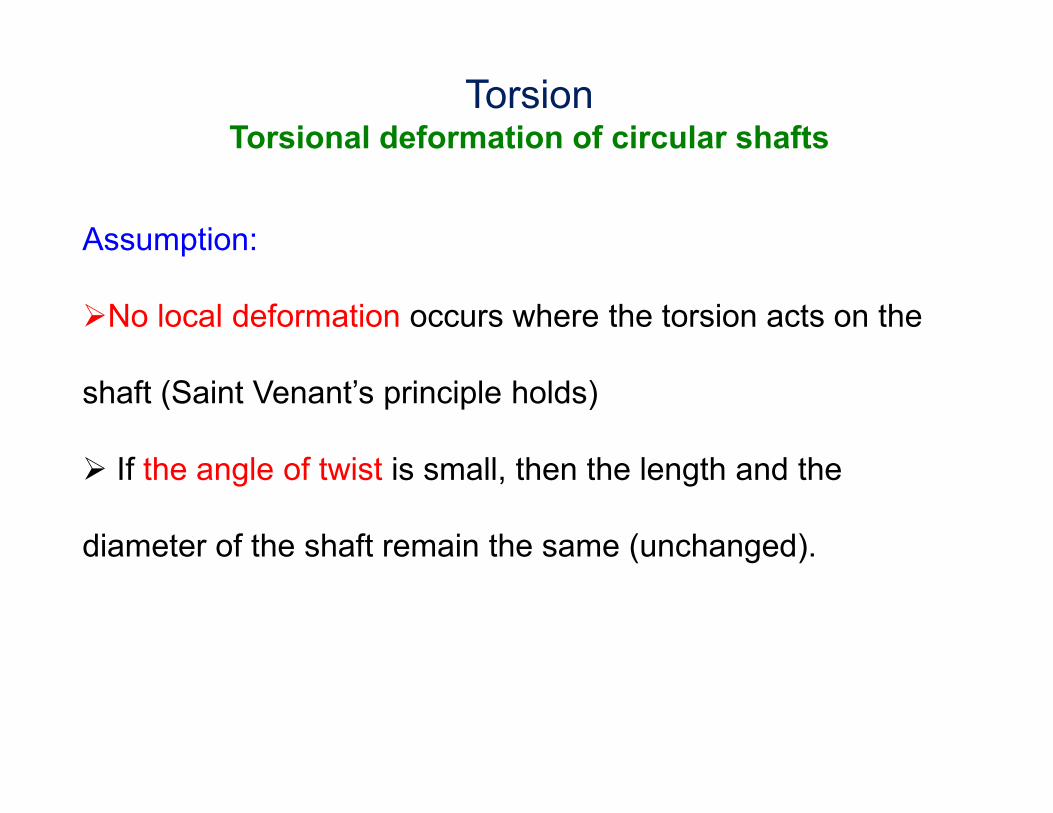
Assumption:
�No local deformation occurs where the torsion acts on the
shaft (Saint Venant’s principle holds)
� If the angle of twist is small, then the length and the
diameter of the shaft remain the same (unchanged).
TorsionTorsional deformation of circular shafts

� Consider the shaft which is fixed at one end, and the torque of T is applied to the
other end (free end). Notice that the dark-green longitudinal plane is deformed as
follows:
�The radial line at a distance
x from the fixed end rotates
about an angle ϕ(x).
� The angle ϕ(x) is called the
angle of twist, and it is a
function of the distance x.
� ϕ(x) increases with
distance x.
TorsionTorsional deformation of circular shafts
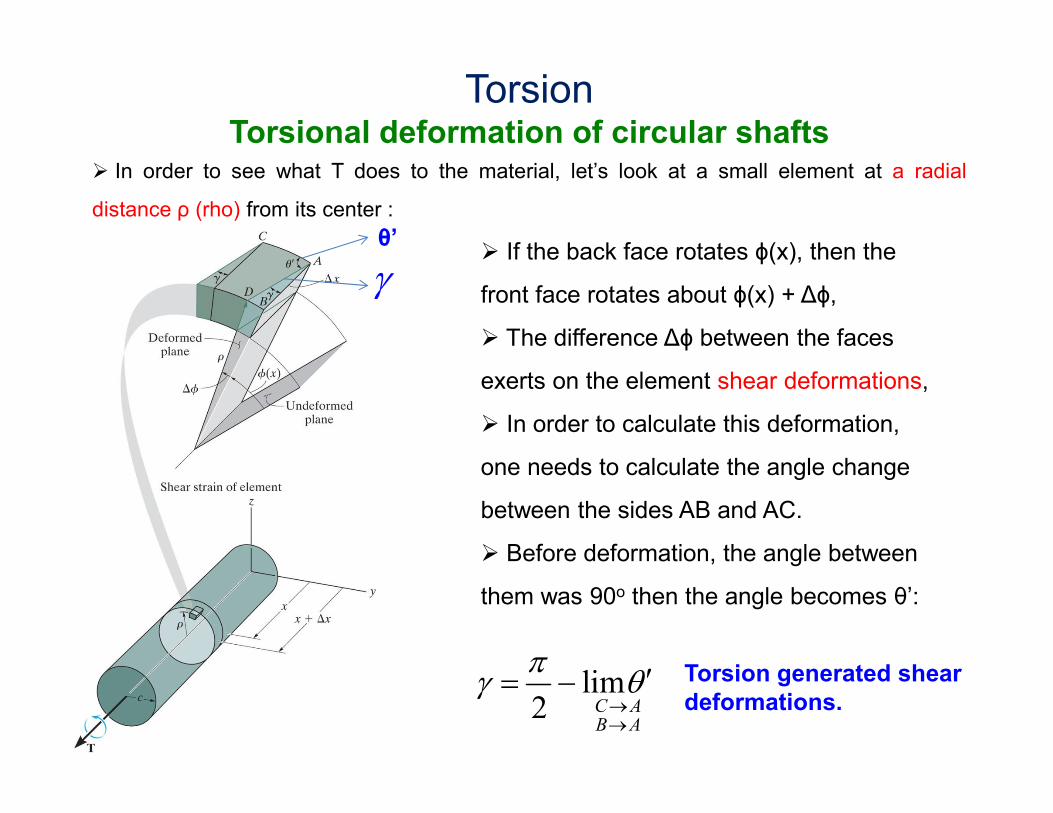
� In order to see what T does to the material, let’s look at a small element at a radial
distance ρ (rho) from its center :
� If the back face rotates ϕ(x), then the
front face rotates about ϕ(x) + Δϕ,
� The difference Δϕ between the faces
exerts on the element shear deformations,
� In order to calculate this deformation,
one needs to calculate the angle change
between the sides AB and AC.
� Before deformation, the angle between
them was 90o then the angle becomes θ’:
θ’
lim2 C A
B A
πγ θ
→→
′= −
γ
Torsion generated shear
deformations.
TorsionTorsional deformation of circular shafts
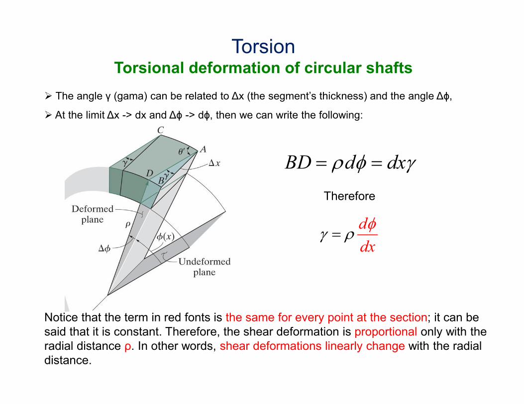
� The angle γ (gama) can be related to Δx (the segment’s thickness) and the angle Δϕ,
� At the limit Δx -> dx and Δϕ -> dϕ, then we can write the following:
BD d dxρ φ γ= =
Therefore
d
dxγ ρ
φ=
Notice that the term in red fonts is the same for every point at the section; it can be
said that it is constant. Therefore, the shear deformation is proportional only with the
radial distance ρ. In other words, shear deformations linearly change with the radial
distance.
TorsionTorsional deformation of circular shafts
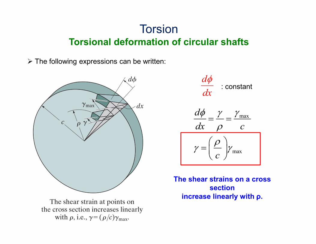
� The following expressions can be written:
max
max
d
dx c
c
γφ γρ
ργ γ
= =
=
The shear strains on a cross
section
increase linearly with ρ.
d
dx
φ: constant
TorsionTorsional deformation of circular shafts

TorsionTorsion Formula
� In this section, we will develop a relationship between internal torsional moment
and shear stresses.
� Shear strains are caused by the shear stresses. Notice that since the change in
shear strains is linear therefore the shear stress change will be linear as well.
If we assume that the material remains
linear elastic under torsional effects, we
can write the following based on the
Hooke’s law:
Gτ γ=
By referring to the figure on the left in a
full circular cross-section, the shear
stresses would start from zero and
linearly increases with the radial
distance, and becomes the largest at
the periphery .

� From the Hooke’s law, also the following expression can be written:
max
c
ρτ τ =
This expression emphasizes that also the
shear stress is a function of ρ.
� Due to the equilibrium, internal torque must be equal to the external torque T.
We can write the force on a infinitesimally small area dA as dF = (τ)dA. The
torque due to this force is dT = ρ(τdA). If we integrate that
( ) 2max
maxA A A
T dA dA dAc c
τρρ τ ρ τ ρ = = =
∫ ∫ ∫
TorsionTorsion Formula

2max
A
T dAc
τρ= ∫
� The integral given above is related to the geometry of the cross-section, and
it is known as the polar moment of inertia of the cross-section. This value is
designated as J. The formula can be rewritten as follows:
max
TcJ
τ =
Maximum shear
stress at the
cross-section
Internal torque at
the cross-section
Radius of the
cross-section.
TorsionTorsion Formula

� By using the formulas given below, we can derive a general expression to
find shear stress at any point on the cross-section.
max
c
ρτ τ =
max
TcJ
τ =
T
Jτ ρ=
This formula is known to be the torsion formula.
It can be used for circular shafts and
if the material is homogenous and linear elastic.
TorsionTorsion Formula

TorsionPolar moment of inertia (for full circular sections)
� Polar moment of inertia of a full circular cross-section can be found as follows:
( )2 2 3
0
4
02
2 2
c c
A
d cJ A d dρ ρπ
πρ ρ π ρ ρ= = = =∫ ∫ ∫
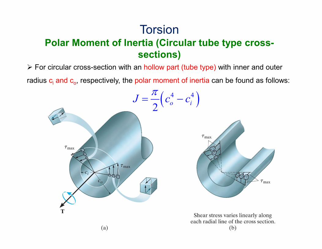
TorsionPolar Moment of Inertia (Circular tube type cross-
sections)
� For circular cross-section with an hollow part (tube type) with inner and outer
radius ci and co, respectively, the polar moment of inertia can be found as follows:
( )4 4
2o i
J c cπ
= −

Shear stresses increases
linearly along the radial
path.
Failure due to Torsion
EXAMPLE 13.1
EXAMPLE 13.1

EXAMPLE 13.1
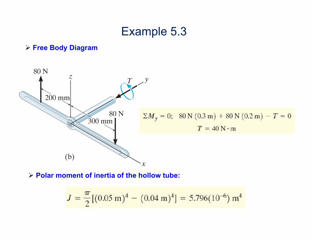
Example 5.3
� Free Body Diagram
� Polar moment of inertia of the hollow tube:

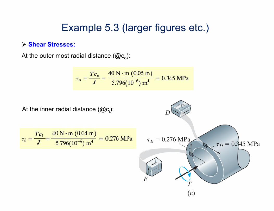
Example 5.3 (larger figures etc.)
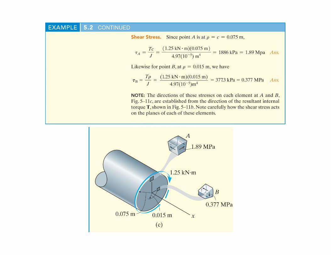
� Shear Stresses:
At the outer most radial distance (@co):
At the inner radial distance (@ci):

EXAMPLE 13.1 Hint:
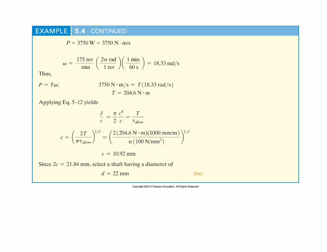
P = T × ω
where
P: power in Watt (N.m/s)
T: Torque in N.m
ω: frequency in rad/sec
EXAMPLE 13.1