torno crank - donuts · 2019-01-08 · - always observe all of the specified tightening torques for...
TRANSCRIPT
USER MANUAL
REV
.01-
04.2
018
TORNO CRANK

2
CONTENT
INTRODUCTIONPreface 3
SAFETY 4Intended use 4 Fundamental safety precautions 4Assembly and maintenance 4On the road 4Transport and storage 4
TECHNICAL SPECIFICATIONS 5 Delivery specifications 5Bottom bracket 6Size 7Tightening torques 7Application area 7
ASSEMBLY 8Installing the TORNO crankset 8Preparing the frame 8Installing the bottom bracket 8BSA/ITA 9BB30/PressFit 30/BBrightTM PressFit 9Press-fit/EVO386 10Assembling the chainring 10Adjusting unit 10Installing the crank 11Assembling the pedals 14
DISASSEMBLY 15
MAINTENANCE 16Important maintenance information 16Before every journey 16Checking the bottom bracket clearance 17Regualr maintenance 17Dismantling the bottom bracket 18Pres Fit / EVO386 19
3
INTRODUCTION
PREFACE
This manual is an integral part of your 3T component and it provides you with information regar-ding the safe operation of your 3T Torno crank system.Read this manual carefully prior to assembling your 3T component. Always read and observe all of the assembly and maintenance instructions in this manual, as well as those provided in the ma-nuals of other manufacturers whose products are used on your bicycle (e.g. frame, chainwheels, pedals, etc.).
Retain this manual for other users of your 3T components. Make sure that all users read, under-stand and observe this manual.If you ever sell or give away your 3T components, this manual should be transferred to the new owner.
4
SAFETY
INTENDED USE
ASSEMBLY & MAINTENANCE
ON THE ROAD
TRANSPORT AND STORAGE
FUNDAMENTAL SAFETY PRECAUTIONS
WARNINGAny use differing from that intended could cause an accident and result in death or serious injury.
WARNINGRisk of accident caused by assembly and maintenance work which has not been conducted in aprofessional manner.- Do not overestimate your technical ability. All assembly and maintenance work should be per-
formed by a specialist workshop for bicycles. This is the only way to ensure the work is con-ducted in a professional manner.
- Always observe all of the specified tightening torques for the screw connections.- Only use suitable, undamaged, high-quality tools.- Only ever use original 3T components which are available from your specialist dealer or directly
from 3T.- Never make any modifications to your 3T components.- Check your crank system (incl. cranks, bottom bracket, chainwheels) to make sure it is undama-
ged and functioning properly before every journey. Send us your 3T Torno component before further use if damage is visible (cracks, fractures, deformations, etc.) or if you are in any doubt about its functionality.
WARNINGDanger of accidents due to improper behaviour or improper equipment during riding .
WARNINGRisk of accident caused by damaged bicycle components.- Always transport your bicycle in an appropriate and careful manner.- Do not store your 3T components at an ambient temperature below -15°C (5°F) or above
55°C (131°F).
The following warnings for the 3T Torno component apply to all Torno models (Torno LTD and Torno TEAM), unless otherwise specified.For the time being we limit the service life of your 3T Torno crank system to 100,000 km or10 years. It is imperative you contact us before continuing to use your 3T Torno crank systemafter one of these limits has expired!
3T Torno crank systems have been exclusively designed for installation on standard road and gravel bikes. For the permitted area of application – see Area of application, page 8.

1 2
4
3 5
6 7
8
9
10
12
11
5
TECHNICAL SPECIFICATIONS
DELIVERY SPECIFICATIONS
1 Fixing bolt 7 Bearing cup, right
2 Left crankarm 8 Spacer, 2.5 mm
3 Adjustment unit ring 9 Chainring
4 Adjustment unit screw, 2x M2.5 x 3 mm
10 Extractor bolt
5 Adjustment unit sleeve 11 Right crankarm
6 Bearing cup, left 12 Chainring screw x4
6
A D
B E
C F
TECHNICAL SPECIFICATIONS
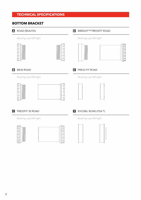
BOTTOM BRACKET
ROAD (BSA/ITA)
Bearing cup left/right Bearing cup left/right
Bearing cup left/right Bearing cup left/right
Bearing cup left/right Bearing cup left/right
BBRIGHT™ PRESSFIT ROAD
BB30 ROAD PRESS-FIT ROAD
PRESSFIT 30 ROAD EVO386: ROAD (FSA ®)
B1 B2
A
C
D
7
TECHNICAL SPECIFICATIONS
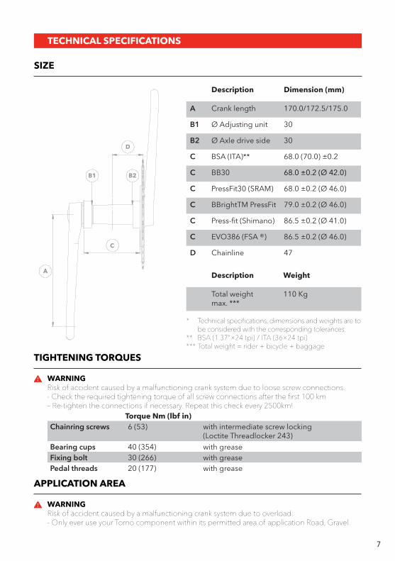
SIZE
* Technical specifications, dimensions and weights are to be considered with the corresponding tolerances.
** BSA (1.37”×24 tpi) / ITA (36×24 tpi)*** Total weight = rider + bicycle + baggage
Description Dimension (mm)
A Crank length 170.0/172.5/175.0
B1 Ø Adjusting unit 30
B2 Ø Axle drive side 30
C BSA (ITA)** 68.0 (70.0) ±0.2
C BB30 68.0 ±0.2 (Ø 42.0)
C PressFit30 (SRAM) 68.0 ±0.2 (Ø 46.0)
C BBrightTM PressFit 79.0 ±0.2 (Ø 46.0)
C Press-fit (Shimano) 86.5 ±0.2 (Ø 41.0)
C EVO386 (FSA ®) 86.5 ±0.2 (Ø 46.0)
D Chainline 47
Torque Nm (lbf in)Chainring screws 6 (53) with intermediate screw locking
(Loctite Threadlocker 243)Bearing cups 40 (354) with greaseFixing bolt 30 (266) with greasePedal threads 20 (177) with grease
Description Weight
Total weight max. ***
110 Kg
TIGHTENING TORQUES
APPLICATION AREA
WARNINGRisk of accident caused by a malfunctioning crank system due to loose screw connections.- Check the required tightening torque of all screw connections after the first 100 km– Re-tighten the connections if necessary. Repeat this check every 2500km!
WARNINGRisk of accident caused by a malfunctioning crank system due to overload.- Only ever use your Torno component within its permitted area of application Road, Gravel.

ASSEMBLY
INSTALLING THE TORNO CRANKSET
INSTALLING THE BOTTOM BRACKET
PREPARING THE FRAME
WARNINGIf not properly performed, assembly and maintenance work could cause accidents resulting in serious or fatal injury.- Do not overestimate your technical ability. All assembly and maintenance work should be per-
formed by a 3T authorized dealer. This is the only way to ensure the work is conducted in a professional manner.
WARNINGDo not use aggressive solvents that can damage the frame.
Secure your bicycle in an appropriate assembly stand.If necessary remove the crankset and the old bottom bracket.If necessary use cleaning solvent or other similar agents to clean the bottom bracket housing of your frame.
Make sure that the edges of the bottom bracket housing are plane, parallel, milled to the correct dimension and free of burrs – see Size, page 7.Double check the width of the bottom bracket housing of your bicycle frame.If necessary rework the bottom bracket housing using an appropriate milling tool (Cyclus, ParkTool or other similar tool).Make sure that the threads of the bottom bracket housing are clean, free from paint residues and adequately tapped into the housing.If necessary, rework the threads with an appropriate cutting tool (Cyclus, ParkTool or other similar tool).
Make sure that the securing bolt of the derailleur cable guide does not protrude into the bottom bracket housing by more than 1mm.Apply grease to the threads and contact surfaces of the bearing cups.
<1
8

ASSEMBLY
L
BSA & ITA BSA
ITA
R
2 1
4 3
9
BB30/PRESSFIT 30/BBRIGHTTM PRESSFIT
When dealing with BB30, PressFit 30 ant BBrightTM PressFit bottom brackets, the bearing cup with internal thread (2) or (4) is always located to the DS, while the bearing cup with external thread (3) or (5) is always located to the NDS.– see Bottom bracket, page 6.
BSA/ITA
Screw the drive side bearing cup (DS) (initially by hand) into the drive side of the bottom bracket housing using an anti-clockwise (BSA) or clockwise (ITA) motion.Screw the non-drive side bearing cup (NDS) (initially by hand) into the non-drive side of the bottom bracket housing using a clockwise motion (BSA & ITA). Tighten both bearing cups using a tightening torque of 40N·m (354lbf·in).
Insert the bearing cup (1) or (3) by hand as far as possible into the DS of the bottom bracket housing.Screw the bearing cup (2) or (4) by hand as far as possible into the NDS bearing cup using a clockwise rotation.Make sure that both bearing cups are located concentrically in front of the bottom bracket housing.Tighten the bearing cup (2) or (4) using a tightening torque of 40N·m (354lbf·in).
A
D B
C
1
2
3
10
ASSEMBLY
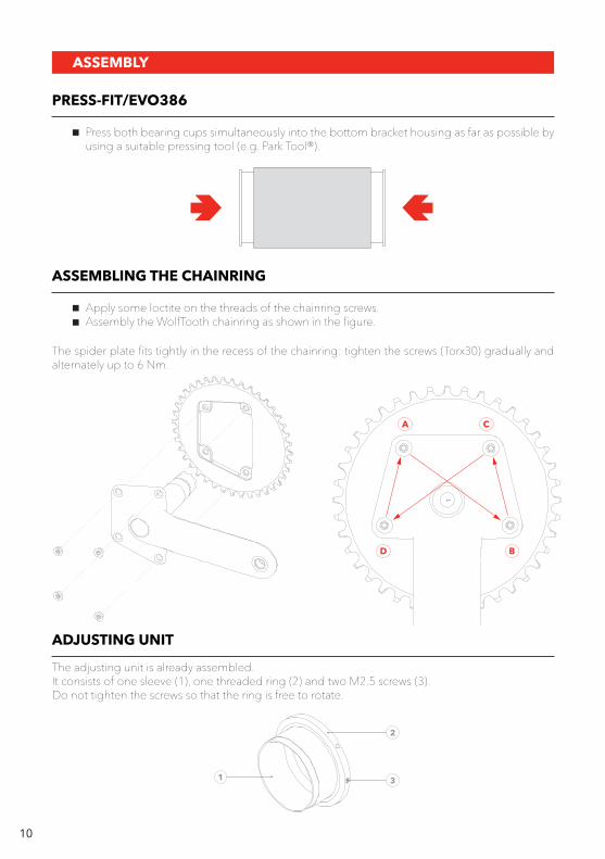
PRESS-FIT/EVO386
ASSEMBLING THE CHAINRING
Press both bearing cups simultaneously into the bottom bracket housing as far as possible by using a suitable pressing tool (e.g. Park Tool®).
Apply some loctite on the threads of the chainring screws.Assembly the WolfTooth chainring as shown in the figure.
The spider plate fits tightly in the recess of the chainring: tighten the screws (Torx30) gradually and alternately up to 6 Nm.
ADJUSTING UNIT
The adjusting unit is already assembled.It consists of one sleeve (1), one threaded ring (2) and two M2.5 screws (3).Do not tighten the screws so that the ring is free to rotate.
ASSEMBLY
left42.5 to 44.2
right45.25
Bearings width usable range87.75 to 89.45
11
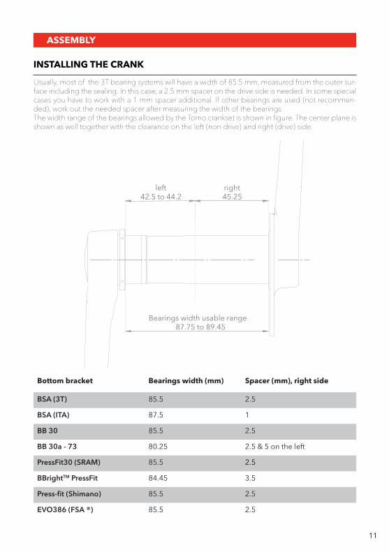
INSTALLING THE CRANK
Usually, most of the 3T bearing systems will have a width of 85.5 mm, measured from the outer sur-face including the sealing. In this case, a 2.5 mm spacer on the drive side is needed. In some special cases you have to work with a 1 mm spacer additional. If other bearings are used (not recommen-ded), work out the needed spacer after measuring the width of the bearings.The width range of the bearings allowed by the Torno crankset is shown in figure. The center plane is shown as well together with the clearance on the left (non-drive) and right (drive) side.
Bottom bracket Bearings width (mm) Spacer (mm), right side
BSA (3T) 85.5 2.5
BSA (ITA) 87.5 1
BB 30 85.5 2.5
BB 30a - 73 80.25 2.5 & 5 on the left
PressFit30 (SRAM) 85.5 2.5
BBrightTM PressFit 84.45 3.5
Press-fit (Shimano) 85.5 2.5
EVO386 (FSA ®) 85.5 2.5
12
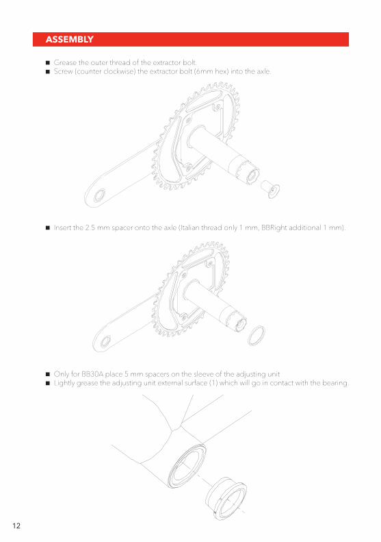
Grease the outer thread of the extractor bolt.Screw (counter clockwise) the extractor bolt (6mm hex) into the axle.
Only for BB30A place 5 mm spacers on the sleeve of the adjusting unit Lightly grease the adjusting unit external surface (1) which will go in contact with the bearing.
Insert the 2.5 mm spacer onto the axle (Italian thread only 1 mm, BBRight additional 1 mm).
ASSEMBLY
2 3
13
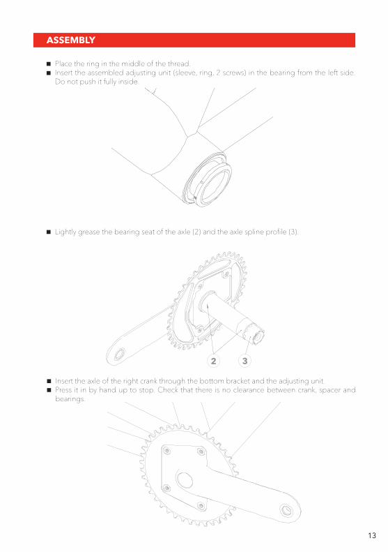
Place the ring in the middle of the thread.Insert the assembled adjusting unit (sleeve, ring, 2 screws) in the bearing from the left side. Do not push it fully inside.
ASSEMBLY
Lightly grease the bearing seat of the axle (2) and the axle spline profile (3).
Insert the axle of the right crank through the bottom bracket and the adjusting unit. Press it in by hand up to stop. Check that there is no clearance between crank, spacer and bearings.
14
ASSEMBLY
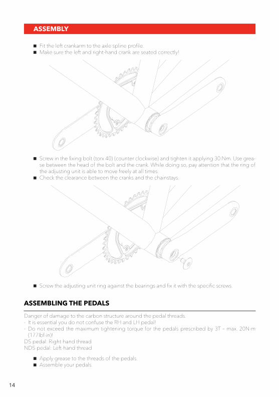
Screw in the fixing bolt (torx 40) (counter clockwise) and tighten it applying 30 Nm. Use grea-se between the head of the bolt and the crank. While doing so, pay attention that the ring of the adjusting unit is able to move freely at all times.Check the clearance between the cranks and the chainstays.
Fit the left crankarm to the axle spline profile.Make sure the left and right-hand crank are seated correctly!
Screw the adjusting unit ring against the bearings and fix it with the specific screws.
ASSEMBLING THE PEDALS
Danger of damage to the carbon structure around the pedal threads.- It is essential you do not confuse the RH and LH pedal!- Do not exceed the maximum tightening torque for the pedals prescribed by 3T – max. 20N·m
(177lbf·in)!DS pedal: Right-hand threadNDS pedal: Left-hand thread
Apply grease to the threads of the pedals.Assemble your pedals.

15
Remove fixing bolt (clockwise)Use a 6 mm Hex key on the extractor bolt from the non-drive side. Loosen it (clockwise) and push the left crankarm off.
DISASSEMBLY
Remove right crankarm pushing the axle out of the bearings.Remove the metal sleeve.
16
MAINTENANCE
IMPORTANT MAINTENANCE INFORMATION
BEFORE EVERY JOURNEY
WARNINGIf not properly performed, assembly and maintenance work could cause accidents resulting in death or serious injury.- Do not overestimate your technical ability. All assembly and maintenance work should be per-
formed by a specialist workshop for bicycles. This is the only way to ensure the work is con-ducted in a professional manner.
WARNINGRisk of accident caused by material damage or improper assembly.- Check your 3T components before each journey to ensure the surfaces are completely unda-
maged. Send us your 3T components for inspection before further use if damage is visible (deep scratches in the paintwork which extend into the carbon structure, large abrasions, etc.), if you are in any doubt about their functionality.
- Do not exceed the maximum overall weight for which your 3T components have been appro-ved – see Size, page 7.
WARNINGRisk of accident caused by damaged components.- Always read and observe all of the assembly and maintenance instructions in this manual, as
well as those provided in the manuals of other manufacturers whose products are used on your bicycle (e.g. frame, chainwheels, pedals, etc.).
- Always observe the minimum and maximum values specified (page 7).- Only use suitable, undamaged, high-quality tools.- When conducting assembly steps that require a specific tightening torque, always use an ap-
propriate torque wrench that is designed for the tightening torque specified.
Improperly performed assembly and maintenance work could also result in a loss of your warranty rights (liability for defects)!
Never use a high-pressure cleaner or steam cleaner to clean your bicycle, as the seals of your bicycle components are not able to withstand the pressure. If such cleaners are used, it would result in cor-rosion and material damage.Never use caustic solvents (such as paint thinners, acetone, nitro compounds, etc.) as they can attack the surface of your 3T components.Only use commercially available paint care products and water to clean your 3T components.Spirit or petrol should be used carefully- when using such products avoid excessive wiping and prolonged exposure times.Always ensure your bicycle is maintained in a flawless condition. Care and maintenance will prolong the service life of your bicycle and its components and improve your personal safety!If you suspect that your bicycle is defective or is not functioning properly, stop using it and contact a specialist bicycle workshop immediately!
17
MAINTENANCE
CHECKING THE BOTTOM BRACKET CLEARANCE
REGUALR MAINTENANCE
Grasp both cranks of your bicycle.Try to move the cranks to the left and right.If you feel bearing play, it means that the bottom bracket is loose and needs to be adjusted immedia-tely. In this case, disassembly the crank and repeat the installation paying attention to the following:
The maintenance intervals required for your bicycle depend on how often and in which weather conditions it is used.The following maintenance measures should be conducted more frequently if the bicycle is used in extreme conditions (rain, dirt, long distances, etc.).When conducting regular maintenance procedures make sure your bicycle is always clean and well protected by lubricants and cleaning agents. Ask your specialist dealer about appropriate lubricants and cleaning agents as well as information relating to their correct application.
Remove the chain from the chainwheel and place it onto the bottom bracket housing.The bottom bracket can now be rotated freely.Use two fingers to grasp one of the cranks directly by the bottom bracket axle and rotate the axle in its bearing.If the bottom bracket axle rotates with perceptible resistance, it means that the bottom bracket is too tight and must be adjusted immediately.In this case redo the assembly of the crankset paying attention to the steps described above.
Insert the adjustment unit into the bearing only about 5 mm.Insert the right crank up against its stop and check there is no clearance between the crank, the spacer and the bearing.Tighten the fixing bolt using 30 NmWhile doing so, pay attention that the ring of the adjusting unit is able to move freely at all times.
Clean your 3T-components at regular intervals by using water and a non-abrasive, environ-mentally friendly cleaning agent.When cleaning your 3T components always check for signs of damage (dents, cracks, scra-tches, large abrasions, worn areas, etc.).
WARNINGRisk of accident caused by a malfunctioning crank system due to loose screw connections.- Check the required tightening torque of all screw connections after the first 100 km – re-tighten the
connections if necessary. Repeat this check every 2500km! Apply fresh thread lock if necessary.
WARNINGRisk of damage to the bearings.- Never try to remove the bearing seals from the bottom bracket.- Your THM bottom bracket is elaborately sealed and provided with permanent lubrication. There is no need to re-lubricate the bearings!
8 mm
8 mm
3
3
2
2
1
2 1
4
34
8 mm
8 mm
3
3
2
2
1
2 1
4
34
8 mm
8 mm
3
3
2
2
1
2 1
4
34
18
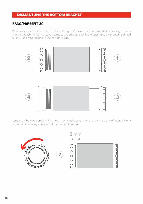
DISMANTLING THE BOTTOM BRACKET
BB30/PRESSFIT 30
When dealing with BB30, PressFit 30 and BBrightTM PressFit bottom brackets the bearing cup with internal thread (1) or (3) is always located to the drive side, while the bearing cup with external thread (2) or (4) is always located to the non-drive side.
Loosen the bearing cup (2) or (3) using an anticlockwise rotation until there is a gap of approx. 8 mm between the bearing cup and bottom bracket housing.
8 mm
8 mm
3
3
2
2
1
2 1
4
34
8 mm
8 mm
3
3
2
2
1
2 1
4
34
8 mm
8 mm
3
3
2
2
1
2 1
4
34
19
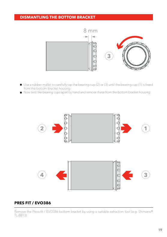
DISMANTLING THE BOTTOM BRACKET
Use a rubber mallet to carefully tap the bearing cup (2) or (3) until the bearing cup (1) is freed from the bottom bracket housing. Now twist the bearing cups apart by hand and remove these from the bottom bracket housing.
PRES FIT / EVO386
Remove the Press-fit / EVO386 bottom bracket by using a suitable extraction tool (e.g. Shimano® TL-BB13).

3T.BIKE