tornado resistance design review criteria for
TRANSCRIPT

TORNADO RESISTANCE DESIGN REVIEW CRITERIA
SAN ONOFRE NUCLEAR GENERATING STATION UNIT 1
FOR
SOUTHERN CALIFORNIA EDISON COMPANY 2244 WALNUT GROVE AVENUE
ROSEMEAD, CA 91770
Cygna Document Number DC-85028-01 Revision 0
October, 1985
Prepared by v t k U. Hamps i e Date
Structural Review by/
Day ate
Systems Review by Izz11
C. D. Ilers Date
Approved by 4k .1 gh ae
Cygna Energy Services 101 California Street, Suite 1000 San Francisco, California 94111
8612010110 861121 PDR ADOCK 05000206 P PDR

TABLE OF CONTENTS
Page
1.0 Introduction 1-1
2.0 Design Review Approach 2-1
2.1 Identification of Structures, Systems and Components 2-1
2.2 Deterministic Evaluation 2-2
2.3 Probabilistic Evaluation 2-4
2.4 Design Basis Tornado 2-5
3.0 Loads 3-1
3.1 Tornado Loads 3-1
3.1.1 Tornado Wind Load 3-2
3.1.2 Tornado Differential Pressure Load 3-3
3.1.3 Tornado Missile Load 3-4
3.2 Straight Wind Loads 3-6
3.3 Normal Operating Loads 3-7
4.0 Load Combinations 4-1
5.0. Acceptance Criteria 5-1
5.1 Concrete Structures 5-1
5.2 Steel Structures 5-2
5.3 Reinforced Concrete Masonry 5-4
5.4 Piping Components 5-5
5.5 Pipe Supports 5-6
5.6 Electrical Raceway Supports 5-9
5.7 Tanks and Miscellaneous Equipment 5-12
SotenClfri Edison Company Page i
- --... San Onofre Nuclear Generating Station Unit 1
,iiiiii~g~iniII~IDocument No. DC-85028-O1, Rev. 0

TABLE OF CONTENTS
(continued)
Page
5.8 Material Allowables and Design Strengths 5-15
5.9 Component Evaluation 5-17
5.9.1 Boundary Perforation 5-17
5.9.2 Loss of Operability 5-18
5.9.3 Structural Failure 5-19
6.0 Structural Evaluation Methods 6-1
6.1 Tornado Wind Load Evaluation 6-1
6.2 Differential Pressure Evaluation 6-3
6.3 Tornado Missile Loads 6-4
6.3.1 Local Impact Effects 6-4
6.3.2 Global, Structural Effects 6-6
. 7.0 Alternate Tornado Shutdown System Selection Criteria 7-1
7.1 General Criteria 7-1
7.2 Existing Systems 7-1
8.0 Bibliography 8-1
Appendix A Alternate Tornado Resistance Criteria for
Reinforced Masonry Walls
Southern California Edison Company Page ii _San Onofre Nuclear Generating Station Unit 1
Document No. DC-85028-01, Rev. 0

. 1.0 INTRODUCTION
This document describes the criteria being used in the tornado resistance
design review for San Onofre Nuclear Generating Station Unit 1
(SONGS 1). The design review is being performed for the resolution of
SEP Topics 111-2 and III-4.A on "Wind and Tornado Loadings" and "Tornado
Missiles," respectively.
The NRC has summarized their position on SEP-Topics 111-2 and III-4.A for
SONGS 1 in SER's contained in [4] and [5]. The review criteria have been
defined to comply with the NRC criteria and specifically, to ensure the
availability of structures, systems, and components that are required to
assure:
a. capability to shutdown the reactor and maintain it in a safe
shutdown condition, and
b. the capability to prevent accidents which could result in an
increase of offsite exposures.
These criteria are used to evaluate the current straight wind and tornado
design resistance of SONGS 1, as well as to quantify the upgrades
required for different tornado wind speeds as defined in [14], and to
determine the design basis tornado event.
The straight wind and tornado wind speeds being considered are those
corresponding to probabilities of occurrence down to 10-7 per year.
*_Southern California Edison Company P.age 1 - 1 -# - San Onofre Nuclear Generating Station Unit 1
II IIII Document No. OC-85028-01, Rev. 0

2.0 DESIGN REVIEW APPROACH
The approach used in the design review involves five basic steps. First,
structures, systems and components required for plant shutdown are
identified. Next, they are deterministically evaluated against SEP
criteria to determine availability following a tornado event. For
structures, systems and components which do not pass the deterministic
evaluation, a probabalistic evaluation is pursued. The evaluations are
performed for four tornado events of specific occurrence probability.
Plant modifications required to control the plant after each tornado
event are conceptualized and their appropriate cost estimated. A
cost/risk evaluation is performed based on these modification costs
relative to plant risk which defines the Design Basis Tornado. This
approach is shown in the flow charts of Figures 2.1 and 2.2.
2.1 Identification of Structures, Systems and Components
The Normal, Abnormal and Emergency Operating Instructions are
reviewed to determine structures, systems and components required to
place and maintain the plant in a safe shutdown condition. Based on
this review the normal and emergency methods for plant shutdown are
evaluated and the necessary components required to perform this
effort identified.
To assure that a failure of one of these components does not
threaten the operability of the entire system, a review of the
associated P&IDs is performed and redundant/alternate equipment
noted. These components, along with their associated power supply
and any structures they may be locate in or connected to, comprise
the structures, systems and components to be evaluated.
Southern California Edison Company P'ge 2 - 1 San Onofre Nuclear Generating Station Unit 1 Document No. DC-85028-01, Rev. 0

2.2 Deterministic Evaluation
The review of these structures, systems and components centers
around those safety related structures, systems and components that
were identified by the NRC [4], [5] as not being able to withstand
the postulated tornado loads or as not being adequately protected
from tornado missiles. The evaluation performed by the NRC was
based on criteria used for licensing new facilities. The SER's were
based on a tornado wind speed of 250 mph and a pressure drop
(differential pressure) of 1.5 psi occurring in 4.5 seconds. Two
postulated missiles were considered, namely a 3 foot steel rod with
a total horizontal velocity of 229 ft/sec and a utility pole with a
total horizontal velocity of 152 ft/sec. Using these tornado and
missile parameters it was concluded that the required concrete
thickness for an adequate missile protection barrier would be 10
inches for the utility pole missile and 6 inches for the steel rod
missile. It was further concluded that masonry walls, generically,
would not provide adequate protection against tornado missiles.
The following structures were considered to have inadequate
resistance to withstand a tornado with a wind speed of 250 mph and a
pressure drop of 1.5 psi:
1. Reactor Auxiliary Building (portions above grade)
2. Turbine building
3. Fuel storage building
4. Portions of the control and administration building other
than the control room
5. Ventilation equipment room
6. Turbine building gantry crane
7. Vent stack
* Southern California Edison Company Piage 2 - 2 W 'San Onofre Nuclear Generating Station Unit 1
Document No. DC-85028-01, Rev. 0

The systems and component items listed in Table 2.1 were considered to be located either in the open or in buildings with inadequate
strength and were therefore considered not to be protected from
tornado missiles.
The sphere enclosure building and the diesel generator building were
considered in the NRC review to be capable of withstanding the 250
mph tornado, as well as being adequately protected from the effects
of tornado missiles. Systems and components that were considered to
have adequate tornado missile protection are listed in Table 2.2.
Table 2.3 defines the scope of equipment targets that are evaluated
as part of the deterministic tornado resistance design review.
The deterministic evaluation will be based on the assumption that
all inadequately protected structures and components are subjected
to the site specified tornado and straight winds of [14] and struck
by the two specifically defined NRC missiles [5]. The resultant
loads will be used to determine the structural adequacy of the
components and structures to perform their required safe shutdown
functions. If components are determined to fail at a given
windspeed, based on the criteria of Table 2.4, modifications
required to protect them are conceptualized in order to allow an
overall cost risk analysis. This methodology is shown in Figure
2.1.
In addition to the potential failure of safety related structures,
systems, and components by postulated tornado missiles, safety
related active components are also reyiewed for potential failure
due to sand impingement.
Southern California Edison Company Pge 2 - 3 San Onofre Nuclear Generating Station Unit 1 Document No. DC-85028-01, Rev. 0

For those active components not located in protected structures a
review is performed to determine if sand could enter into the
component's casing or affect exposed bearings. If it is determined
that no visible pathway is available for sand to enter the
component's casing or affect the bearings, the component will be
considered protected and no further evaluation is required.
2.3 Probabilistic Evaluation
For those structures, systems and components considered to have
adequate tornado missile protection by deterministic evaluation, no
further evaluation is performed. However, equipment not protected
is evaluated to determine what modifications would be required to
comply with these criteria considering their probability of strike
and failure. The methodology used to determine if structures,
systems, and components are protected from postulated tornado
missiles is outlined on Figure 2.2.
To determine the probability of failure a Monte Carlo simulation
methodology and a simulation computer code TORMIS, which quantifies
tornado wind load and tornado-generated missile risk, is used. The
TORMIS-simulation code requires three imputs as follows:
1. Three dimensional model of the plant structural and support
configuration;
2. Site specific missile database, and;
3. Site specific windfield database.
Using the three database inputs, TORMIS determines, for each
structure and component, the probability of strike and failure for
each of the site specific missiles.
Southern California Edison Company Page 2 - 4
- - - cSan Onofre Nuclear Generating Station Unit 1 - EE ?-1Document No. DC-85028-01, Rev. O

The plant model--is determined by a review of layout drawings. The
site specific missile database is determined by a site inspection.
The site specific windfield database was determined in a previous
analysis [14].
The probability of strike and failure for each of the structures and
components is determined for tornado wind speeds with a probability
of occurrence from 10-4 to 10-7 per year. At each of these probable
wind speed occurrences a risk simulation using a set of TORMIS code
options is performed. To facilitate comparison among alternate
damage criteria, four definitions of the impact event are utilized
[24].
1. Missile impact
2. Missile impact with a velocity greater than a specified value
3. Barrier damage evaluation for a specified thickness.
4. Barrier damage evaluation for an alternate thickness greater
than the thickness in event 3 above.
This methodology is shown in Figure 2.2 and the criteria used to
determine if failure will occur is outlined in Table 2.4.
2.4 Design Basis Tornado
Once it is determined that a structure, system or component will
fail a conceptual modification and associated cost to protect it is
developed. This information is used to perform a cost/risk
evaluation for each of the wind events. Based on this evaluation it
is determined at what probable wind speed occurrence it is cost
beneficial to backfit the plant. The windspeeds associated with
this probability of occurrence represent the SONGS 1 Design Basis
Tornado.
Southern California Edison Company Page 2 - 5
San Onofre Nuclear Generating Station Unit 1 0 .Document No. DC-85028-01, Rev. 0

Upon determination of the Design Basis Tornado a review of the safe
shutdown systems will again be performed. This review is performed
to define the minimum set of structures, systems and equipment
available to place and maintain the plant in a safe shutdown
condition. If sufficient systems and equipment are not available,
modifications will be implemented to protect those necessary
components.
_ _ Southern California Edison Company Page 2 - 6 San Onofre Nuclear Generating Station Unit 1 Document No. DC-85028-01, Rev. 0

Table 2.1
Systems And Components Not Protected From Tornado Missiles Per NRC Review
(Based on 250 MPH Tornado Wind Velocity)
1 Atmospheric dump valves and steam dump control system
2 Turbine and motor-driven auxiliary feed pumps (Auxiliary
Feedwater System)
3 Water source - Condensate Storage Tank
4 Component Cooling Water System
5 Salt Water Cooling System
6 Chemical and Volume Control System
7 Refueling Water Storage Tank
8 Instrument Air System
9 Spent fuel pool storage and spent fuel pit cooling system
10 Boron Injection System
11 Ventilation system for the control room
12 Control Room
13 Safety Injection System
*14 Instrumentation for shutdown
15 Emergency power (AC and DC)
16 Main Steam and Main Feedwater System
_________Southern California Edison Company Page 2 -7 -San Onofre Nuclear Generating Station Unit 1
,F Document No. DC-85028-01, Rev. 0

Table 2.2
Tornado issile Protected System and Component Per NRC Review
(Based on 250 sph Tornado Wind Velocity)
1 Reactor Coolant Pressure Boundary
2 Steam Generators
3 Pressurizer
4 Charging Pumps
5 Diesel Generators
6 Diesel Fuel Supply
7 No. 2 125 VDC Bus, Battery and Battery Chargers
8 Control Rod Drive System
9 Liquid Radwaste System
10 Gaseous Radwaste System
11 Reactor Core and Fuel Assemblies
12 Main Steam System Inside Containment
13 Feedwater System Inside Containment
14 RHR System Inside Containment
15 Boron Injection System Inside Containment
16 Spent Fuel Pit Boundary
17 Instrumentation Inside Containment
_________Southern California Edison Company Page 2 -8 ---- San Onofre Nuclear Generating Station Unit 1
- --- - 2 Document No. DC-85028-01, Rev. 0
Table 2.3
Potential Targets to be Evaluated in the Tornado Resistance Design Review
1 Main Steam Lines & Associated Relief and Dump Valves outside containment
up to and including the Turbine Stop Valves
2 Main Feedwater Pumps and Piping outside containment
3 Motor Driven and Turbine Driven Auxiliary Feedwater Pumps and Piping
4 Condensate Storage Tank
5 Component Cooling Water Surge Tank
6 Component Cooling Water Pumps and Piping in backyard
7 Component Cooling Water Heat Exchanger
8 Refueling Water Storage Tank
9 Auxiliary Feedwater Storage Tank
10 Remote Shutdown Panel
11 Control Room and Control Room HVAC
12 RCP Seal Water Return Valve
13 Salt Water Cooling Pumps and Piping
14 Volume Control Tank
15 Boric Acid Tanks, Pumps and Piping
16 Gaseous Nitrogen System
17 Dedicated Manual Transfer Switches at Auxiliary Feedwater & Charging
Pumps
18 Instrument Air System
19 Auxiliary Feedwater System Flow Control Valves
20 Primary Plant Make-up Water Storage Tank
21 Auxiliary Salt Water Cooling Pump and Piping
22 Recirculation Heat Exchanger
23 Steam Generator Blowdown Valves and Piping
24 CCW Piping and Valves in Valve Alley
25 Spent Fuel Pit Heat Exchanger
26 Instrument A.C. Power Supplies
27 4160V Switchgear
Southern California Edison Company Pace 2 - 9 San Onofre Nuclear Generating Station Unit 1 Document No. DC-85028-01, Rev. 0

Table 2.3 (cont'd)
28 480V Switchgear 1, 2, & 3 29 4160V/480V Transformers 1, 2 & 3
30 480V Motor Control Centers
31 No. 1 125V D.C. Bus, Battery and Battery Chargers
32 D.C. Power Cables
33 A.C. Power Cables
32 Safe Shutdown Instrumentation Cables
Southern California Edison Company Page 2 - 10 -. San Onofre Nuclear Generating Station Unit 1
WDocument No. DC-85028-01, Rev. 0

TABLE 2.4 COMPONENT CRITERIA
EVALUATION
Failure Mechanism Component Boundary Loss of Structural
Perforation Operability Failure
Piping Section 5.9 NA Section 5.4, 5.5 Active Valves Treated as Piping Note 1 Note 1 Passive Valves Treated as Piping NA NA Instrumentation NA Strike = Failure Strike = Failure Tanks Treated as Piping NA Sections 5.2, 5.7 Heat Exchangers Treated as Piping NA Section 5.2, 5.7 Air/N 2 Tubing Strike = Failure Strike = Failure Strike = Failure N2 Cylinders Treated as Piping NA NA Pumps/Operators Treated as Piping Note 1 & 2 Note 1 Elec. Cabling NA Strike = Failure Strike = Failure Elec. Cable Trays NA NA Sections 5.2, 5.6, 5.9 Elec. Conduit NA NA Sections 5.2, 5.6, 5.9
Elec. Switchgear NA NA Sections 5.6, 5.9 Transformers 5.9 NA Section 5.9
MCCs 5.9 NA Section 5.9
Note 1: Missile impacts and wind loads are assumed at the eccentric center of mass (i.e, valve operator C.G.). Seismic qualification calculations are used to extrapolate seismic loads to acceptable wind/impact loads.
Note 2: Missile impacts are assumed to occur at the most critical location affecting the structural aspect of operability. For example, for pumps this may be the bearing supports or drive shaft.
Southern California Edison Company Page 2 - 11
San Onofre Nuclear Generating Station Unit I - iDocument No. DC-85028-01, Rev. 0

TABLE 2.5
SAN ONOFRE TORNADO MISSILE SUBSET CHARACTERISTICS
Weight Final per Unit Length/Depth
Missile Description Depth Length Amin Ratio Weight (lb.) Subset (Typical) d (in) (lb/ft) (in2) Min. Max. Min. Max.
1* Rebar 1.00 2.67 0.79 36.0 36.0 8 8 2 Gas Cylinder 10.02 38.64 9.45 4.0 10.0 129 323 3 Drum, Tank 19.98 23.55 311.60 2.3 6.0 90 235 4* Utility Pole 13.50 32.06 143.10 31.1 31.1 1122 1122 5 Cable Reel 42.21 140.70 126.60 0.5 0.6 247 297 6* 3" Pipe 3.50 7.58 2.20 34.3 34.3 76 76 7* 6" Pipe 6.63 18.90 5.60 27.2 27.2 284 284 8* 12" Pipe 12.75 49.60 14.60 14.1 14.1 743 743 9 Storage Bin 38.40 112.50 40.50 1.0 7.8 360 2808 10 Concrete Frag. 36.00 326.25 324.00 1.0 3.0 979 2936
Wood Beam 12.00 9.50 48.00 12.0 12.0 114 114
40 Wood Plank 12.00 3.30 12.00 8.0 12.0 26 40 13 Metal Siding 48.00 25.00 24.00 2.0 4.0 200 400 14 Plywood Sheet 48.00 15.02 50.74 2.0 2.0 120 120 15 Wide Flange 11.29 27.87 8.16 8.0 60.0 210 1573
16 Channel Section 5.11 11.88 3.49 9.0 80.0 45 405 17 Light Eqpt. 46.48 44.02 4.63 0.5 5.0 85 853 18 Heavy Eqpt. 67.07 88.67 15.70 0.5 8.0 248 3956
19 Steel Frame,
Grating 43.31 12.37 2.22 1.0 7.5 45 335
20 Large St. Frame 97.41 47.23 11.00 1.0 5.0 383 1917
21* Vehicle 66.00 250.00 2474.00 2.9 2.9 3988 3988
* Denotes membership in NRC standard spectrum of missiles
Southern California Edison Company Pag- 2 - 12 - - San Onofre Nuclear Generating Station Unit 1
- - - -a Document No. DC-85028-01, Rev. 0

Figure 2.1
DETERMINISTIC EVALUATION FLOWCHART
NRC Missiles Site Specific * Utility pole Windfield * Steel rod Database
Targets OK at 10-7 yes windspeed
no
OK at 10-.6 yes wi ndspeed
no
Targets OK at 10-5 yes windspeed
0
Targets OK at 10-4 yes windspeed
Component and Structure Qualification Levels
Southern California Edison Company Page 2 -13
* San Onofre Nuclear Generating Station Unit 1 - Document No. OC-85028-01, Rev. O

Figure 2.2
PROBABILISTIC EVALUATION FLOWCHART
Missile Plant Windfield Database Model Database
Begin TORMIS Evaluation
Probability of:
* missile impact * missile impact at
velocity > allowable * missile penetrating
barrier No. 1 * missile penetrating
barrier No. 2
Damage/Failure probability vs windspeed curve
Southern California Edison Company Page 2 - 14
- _ . - San Onofre Nuclear Generating Station Unit 1 Document No. DC-85028-01, Rev. 0

3.0 LOADS
In addition to the extreme environmental condition loads directly related
to the postulated tornado event, the design review also takes into
consideration sustained (dead weight) loads as well as live loads and
operating loads that may exist concurrently with the tornado event.
The tornado loads are defined in Section 3.1 below.
3.1 Tornado Loads
Tornado intensities in terms of wind speed and pressure drop have
been defined as functions of annual probability of occurrence for the
SONGS 1 site in a report entitled "Tornado Hazard Analysis Relating
to SEP Topic 111-2 at San Onofre Unit 1" [14].
Based on available historical and technical data it is concluded in
[14] that the Western Region tornado defined in USNRC Regulatory
Guide 1.76 [1] is not appropriate for use at SONGS 1. Instead, the
wind effects described in [14] are used in computing structural
effects and missile characteristics at the San Onofre Unit 1 site.
The significant tornado properties for use in the tornado evaluation
as specified in [14] are summarized in Table 3.1.
A tornado can potentially cause damage to a structure through three
principal interaction mechanisms: (1) pressure forces created by air
flowing around and over the structure, (2) pressure forces created by
relatively rapid changes in atmospheric pressure, and (3) impact
forces created by tornado-propelled missiles [15].
*____ Southern California Edison Company Page 3 - 1 San Onofre Nuclear Generating Station Unit 0 Document No. DC-85028-01, Rev. 0

For the structural evaluation, then, the tornado parameters are used
to define the following three categories of structural tornado
loadings:
Tornado Wind Load [WW]
Tornado Differential Pressure Load [W ]
Tornado Missile Load [Wmi
The total tornado load, consisting of a combination of the above
three tornado load categories (Wy, Wp, Wm) is designated Wt.
The individual tornado load components are addressed below in
Sections 3.1.1, 3.1.2, and 3.1.3, while the combination of the
components into total tornado load, Wt, and combination of Wt with
other operating and live loads are discussed in Section 4.0.
3.1.1 Tornado Wind Load
The tornado wind load, Ww, expressed as a maximum velocity
pressure is obtained from the representative tornado wind
speed using the following expression [6]:
P = 0.00256 V2
in which: P = maximum wind load pressure [psf]
V = representative tornado wind speed [mph]
The possibility of load reduction as a result of local
shielding effects may be taken into account when determining
the representative tornado wind speed, V, in this expression.
Southern California Edison Company Page 3 - 2 San Onofre Nuclear Generating Station Unit 1 Document No. DC-85028-01, Rev. 0

The maximum velocity pressure applies at the radius of the tornado funnel at which the maximum velocity occurs. The
tangential velocity varies with the radial distance from the
center of the tornado core. One idealization of this
variation is shown in Figure 3.1 which is obtained from
[15]. This variation, as described in [15], may be taken
into account for design purposes. In cases where structural
dimensions are large compared to the size (radius) of the
tornado this consideration may result in a reduced average
velocity pressure. It should be noted that only the
tangential wind velocity component is characterized by this
variation.
For calculating effective tornado wind velocity pressures on
structural surfaces, shape factors and pressure coefficients
from ASCE Paper No. 3269 [16] or ANSI A58.1 [26] are used.
Gust factors are taken as unity. The effective wind velocity
pressure thus obtained is considered constant with respect to
height when applied to exposed structures [6].
3.1.2 Tornado Differential Pressure Load
The differential pressure variation with respect to tornado
radius is shown schematically in Figure 3.1. The maximum
values of the differential pressures and associated rates of
pressure change for the tornado wind speed probabilities of
interest are included in Table 3.1. The differential
pressure, as shown on Figure 3.1., has its maximum at the
core of the tornado, where the 'tangential wind speed is
zero. This is reflected in the methodology used for
combining the load effects on structures from the two
Southern California Edison Company Page 3 - 3 San Onofre Nuclear Generating Station Unit 1 Document No. DC-85028-01, Rev. 0
different load phenomena, Ww and Wp, as discussed further in Section 4.0.
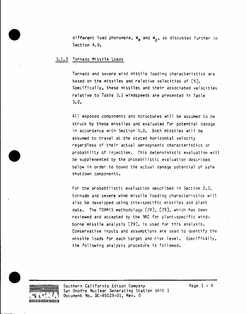
3.1.3 Tornado Missile Loads
Tornado and severe wind missile loading characteristics are
based on the missiles and relative velocities of [5].
Specifically, these missiles and their associated velocities
relative to Table 3.1 windspeeds are presented in Table
3.2.
All exposed components and structures will be assumed to be
struck by these missiles and evaluated for potential damage
in accordance with Section 5.0. Both missiles will be
assumed to travel at the stated horizontal velocity
regardless of their actual aerodynamic characteristics or
probability of injection. This deterministic evaluation will
be supplemented by the probabilistic evaluation described
below in order to bound the actual damage potential of safe
shutdown components.
For the probabilistic evaluation described in Section 2.3,
tornado and severe wind missile loading characteristics will
also be developed using site-specific missiles and plant
data. The TORMIS methodology [24], [25], which has been
reviewed and accepted by the NRC for plant-specific wind
borne missile analysis [29], is used for this analysis.
Conservative inputs and assumptions are used to quantify the
missile loads for each target and risk level. Specifically,
the following analysis procedure is followed.
Southern California Edison Company Page 3 - 4 San Onofre Nuclear Generating Station Unit 1
._ A Document No. DC-85028-01, Rev. 0

Site-Specific Missiles: A site-specific survey of SONGS 1 is
conducted to develop information on the potential types of
missiles at the plant. This data is collected in a form
consistent with the basic missile sets identified in [24].
The numbers and locations of missiles are quantified and the
missile threat to the SONGS 1 shutdown systems determined.
Site-Structures and Targets: Shutdown systems and scenarios
that comprise the targets for the missile load and impact
analysis are modeled for the TORMIS analysis. Tornado-proof
structures that tend to shield these targets from certain
missile sources or directions are included. Non-tornado
proof buildings are also considered potential sources of
missiles.
Tornado and Straight-Wind Frequency Risk: The combined
tornado and straight windspeed frequencies developed in [414]
are used in the analysis. These windspeed frequencies are
used with the TORMIS tornado windfield model for windspeeds
greater than the tornado cross-over windspeeds. Tornado
windfield characteristics are based on site specific data in
[14] as available. For windspeeds below the tornado cross
over windspeeds, straight wind profiles and site-specific
directional characteristics are used.
Missile Injection Criteria: The minimally restrained missile
injection criteria is used in the TORMIS methodology [24],
[25].
Southern California Edison Company Page 3-5
San Onofre Nuclear Generating Station Unit 1 * -- Document No. DC-85028-01, Rev. 0
lilillIllIIIIIIIIIIIIIIIIIIIi

Missile Impact Characteristics and Local Damage
Probabilities: A spectrum of missile impact characteristics
(missile type, mass, velocity) is developed for each
target. In addition, impact (hit) probabilities, failure
probabilities, and local effects damage probabilities are
estimated using the TORMIS methodology. The local effects
analysis includes perforation of steel targets and scabbing
of reinforced concrete targets. An assessment of the missile
effects on critical equipment is made based on the missile
definition and estimated impact velocities (Table 2.4).
3.2 Straight Wind Loads
The curves describing the annual occurence probabilities for fastest
mile straight wind velocity and maximum tornado wind velocity,
respectively, in [14] intersect between the 10-4 and 10-5 probability
levels. Wind speeds due to straight wind and tornadoes are not
directly comparable in terms of effects on structures since effective
pressure calculations and pressure distribution are treated
differently for straight winds and tornadoes. The straight wind case
is, however, conservatively considered the controlling event for the
10-4 annual occurence probability, which is at the upper end of the
range of interest between 10- and 10- Higher probability straight
wind (i.e., lower wind speeds) are thereby not included in the
evaluation.
Straight wind velocities are obtained from [14]. Transformation of
wind velocity to effective pressure applied to structural surfaces is
performed in accordance with ANSI A58.1-1982 [26], using gust factors
corresponding to Exposure D. Exposure D, as defined in [26],
represents coastal areas extending inland 1500 feet from the
shoreline or 10 times the height of the structure under
consideration, whichever is greater.
Southern California Edison Company Page 3- 6 San Onofre Nuclear Generating Station Unit 1 Document No. DC-85028-01, Rev. 0

The velocity pressure, q,, at height Z is determined by the following
equation [26]:
qz = 0.00256 Kz (IV)2
where:
V = basic wind velocity [mph]
Kz = velocity pressure exposure coefficient
I = importance factor = 1.0
The parameter Kz is obtained from [26]. The importance factor, 1, is
taken as unity for this design review because the occurrence
probabilities are accounted for by varying V directly. Pressure and
drag coefficients are obtained from [16] and [26] as applicable to
different types and shapes of structures and components.
3.3 Normal Operating Loads
Normal operating loads include deadloads (0), live loads (L), thermal
operating loads (T ) and pipe reaction Loads (Ro). The live load (L)
is taken to include lateral and vertical liquid pressure as well as
lateral earth pressure as applicable.
Thermal operating loads (TO) and pipe reactions (R0 ) are considered
as applicable for individual structures, unless they are shown to be
secondary and self-limiting in nature. Based on engineering
judgement and accepted industry practice, the total operating loads
(To + R0 ) are assumed to be enveloped by 5% of the dead loads (D),
except for pipe reactions from main stleam and feedwater systems,
which are considered explicitly.
Southern California Edison Company Page 3 - 7 San Onofre Nuclear Generating Station Unit 1 Document No. DC-85028-01, Rev. 0

Table 3.1 Maximum Tornado Load Parameters
and Associated Probabilities of Occurrence [14].
Annual Probability 10-4 10-5 10-6 107
Maximum Horizontal Windspeed [mph] 59(1) 98 136 176
Radius of Maximum Rotational Speed [ft] 52.7 74.3 97.0
Pressure Drop [psi] 0.23 0.47 0.77
Rate of Pressure Drop [psi/sec] 0.11 0.23 0.38
Notes:
(1) At the tornado occurrence probability of 10-4, the straight wind speed of
70 mph is controlling.
Southern California Edison Company Page 3 - 8 San Onofre Nuclear Generating Station Unit 1 Document No. DC-85028-01, Rev. 0

Table 3.2
Tornado Missile Velocities
Horizontal Velocity 'issile Vlocity (FT]SEC)
Missile Basis 1x10- 1x10 1x1O- 1x10⁻⁷
Steel Rod 0.6VT 62 87 120 156 1"0.D. x 3' Lg. Weight = 8lbs
Utility Pole 0.4VT 41 57 79 103 13.5"0.D. x 35'Lg. Weight = 1,4901bs
VT = Total tornado or straight wind velocity
Southern California Edison Company Pege 3 - 9 San Onofre Nuclear Generating Station Unit 1
II Document No. DC-85028-01, Rev. 0

Tornado core
w V/A Constant
z
Oo- VR *Constant z
z I 4I
R c Rjdius
C R ad'us
A c
CM
U (b)
FU 3
0
Tornado core
Ib)
FIGURE 3.1
Variation of wind and atimospheric-pressure change with radius (15]
Southern California Edison Company Page 3 - 10
San Onofre Nuclear Generating Station Unit 1
- - Document No. DC-85028-01, Rev. 0
HiiItIIIIIIuIIIIIIIIIIIlII
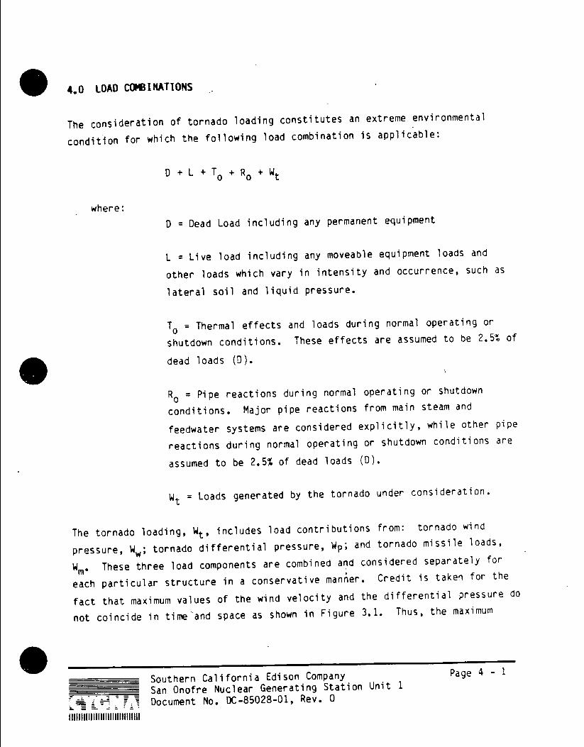
4.0 LOAD COMBINATIONS
The consideration of tornado loading constitutes an extreme environmental
condition for which the following load combination is applicable:
0 + L + T + Ro t
where:
D = Dead Load including any permanent equipment
L = Live load including any moveable equipment loads and
other loads which vary in intensity and occurrence, such as
lateral soil and liquid pressure.
To = Thermal effects and loads during normal operating or
shutdown conditions. These effects are assumed to be 2.5% of
dead loads (D).
Ro = Pipe reactions during normal operating or shutdown
conditions. Major pipe reactions from main steam and
feedwater systems are considered explicitly, while other pipe
reactions during normal operating or shutdown conditions are
assumed to be 2.5% of dead loads (D).
Wt = Loads generated by the tornado under consideration.
The tornado loading, Wt, includes load contributions from: tornado wind
pressure, Ww; tornado differential pressure, Wp; and tornado missile loads,
Wme These three load components are combined and considered separately for
each particular structure in a conservative manner. Credit is taken for the
fact that maximum values of the wind velocity and the differential pressure do
not coincide in time'and space as shown in Figure 3.1. Thus, the maximum
Southern California Edison Company Page 4 - 1
San Onofre Nuclear Generating Station Unit 1
- - I. Document No. DC-85028-01, Rev. 0
IIIIIIIIIIlIIIIIIIIIIII ll1IIII

value of WW is combined with one half of the maximum value of Wp.
The most adverse combined effect of the individual tornado load components is
included in the load combination as Wt. In general the following three
combinations are considered for any particular structure or component [6]:
1. Wt = WP
2. Wt = W + Wm 3. Wt = W + Wm + 0.5 Wp
For consideration of high probability, extreme straight wind loads, W, the
following load combination is applicable:
D + L + T0 + Ro +W
Load symbols in this combination are as defined previously in this section.
Southern California Edison Company Page 4 - 2
San Onofre Nuclear Generating Station Unit 1 Document No. DC-85028-01, Rev. 0

5.0 ACCEPTANCE CRITERIA
5.1 Concrete Structures
For evaluation of extreme environmental conditions, including tornado
effects, the strength design method for concrete is used and the
following structural acceptance criteria apply:
D + L + To + R t < U
where:
D, L, TO, Rot Wt = Loads as defined in section 4.0. A load
factor of 1.0 is implied for each load.
U = Section strength required to resist design loads based on
the strength design methods described in ACI 349 [13].
The criteria above is first satisfied without inclusion of missile
impact load, Wm. When including the concentrated impact load due to
Wm in the combination, local section strength capacities may be
exceeded provided there is no loss of function of any structure or
component required for safe shutdown of the plant; in which case,
maximum allowable ductility ratios are as defined in [3], unless
higher values are demonstrated to be applicable.
For evaluation of higher probability (greater than or equal to 10-4)
straight wind effects, the above acceptance criteria are applicable
with Wt replaced by W.
* __Stouthern California Edison Company Page 5-1 San Onofre Nuclear Generating Station Unit 1
- - = Document No. DC-85028-01, Rev. 0
IIIIIIIIIIIIIIIIIIliIIIIII111
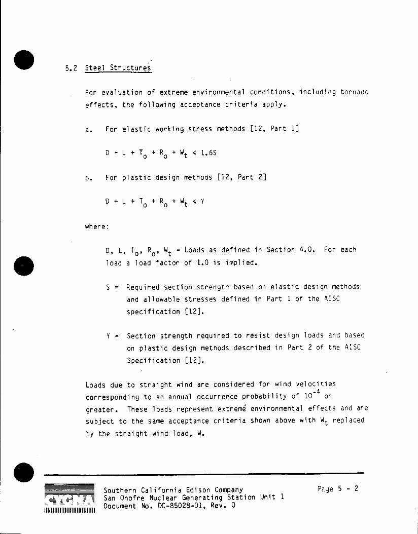
5.2 Steel Structures
For evaluation of extreme environmental conditions, including tornado
effects, the following acceptance criteria apply.
a. For elastic working stress methods [12, Part 1]
D + L + T o + R + Wt < 1.6S
b. For plastic design methods [12, Part 2]
D + L + T + R + Wt < Y
where:
D, L, TO, Ro, W = Loads as defined in Section 4.0. For each
load a load factor of 1.0 is implied.
S = Required section strength based on elastic design methods
and allowable stresses defined in Part 1 of the AISC
specification [12].
Y = Section strength required to resist design loads and based
on plastic design methods described in Part 2 of the AISC
Specification [12].
Loads due to straight wind are considered for wind velocities
corresponding to an annual occurrence probability of 10-4 or
greater. These loads represent extreme environmental effects and are
subject to the same acceptance criteria shown above with Wt replaced
by the straight wind load, W.
Southern California Edison Company Page 5 - 2
San Onofre Nuclear Generating Station Unit 1
Document No. DC-85028-01, Rev. 0

The criteria above are first satisfied without inclusion of missile
impact load, Wi. When including the concentrated impact load due to
W in the combination, local section strength capacities may be
exceeded provided there is no loss of function of any system or
component required for safe shutdown of the unit.
In an inelastic evaluation for missile impact effects on steel
structural elements, the maximum allowable ductility ratios, Wd, are
as follows [8], unless a more detailed ductility capacity analysis is
performed:
Stress Component Maximum Ductility
or Member Type Ratio, id = e/e
Tension due to flexure 10.0
Columns with 1/r < 20 1.3
Columns with 1/r > 20 1.0
Tension 0.5 (e /ey)
where: 1/r = slenderness ratio
= effective member length
r = least radius of gyration
e = strain
e = yield strain
eu = ultimate strain
Southern California Edison Company Paqe 5 - 3
San Onofre Nuclear Generating Station Unit 1
Document No. DC-85028-01, Rev. 0

5.3 Reinforced Concrete Masonry
For evaluation of the reinforced concrete masonry-walls at SONGS 1,
subjected to extreme environmental conditions including tornado
effects, the following acceptance criteria are used:
D + L + T0 + R0 + Wt < U
where:
D, L, To, Ro, W = Loads as defined in Section 4.0
U = Masonry section strength based on elastic design methods
and allowable stresses defined in ACI-531-79 [33] and
increased by factors shown in Table 5.1.
Note: The live load, L, in the combination is considered as
its full value as well as being completely absent.
The criteria above are first satisfied without inclusion of missile
impact loading, Wi. When including the concentrated impact load due
to Wm in the combination, local section strength capacities may be
exceeded provided there is no loss of function of any system or
component required for safe shutdown of the unit.
Loads due to straight wind are considered for wind velocities
corresponding to an annual occurrence probability of 10-4. These
loads represent extreme environmental effects and are subjected to
the same acceptance criteria shown above with Wt replaced by the
straight wind load, W.
In cases where the above criteria provide unacceptable results, the
capacity of reinforced masonry walls to resist straight wind,
tornado and missile impact loads will be determined by alternate
Southern California Edison Company Page 5 - 4
San Onofre Nuclear Generating Station Unit 1
I I Document No. DC-85028-01, Rev. 0
criteria [28].. These criteria are included in Appendix A. These
alternate criteria are based on testing and detailed analytical
studies and state that the determination of ultimate, lateral wind
pressure load capacities for the reinforced concrete block walls is
based on the following criteria [28]:
o Maximum reinforcement steel ductility = 45
o Maximum compressive strain in concrete blocks = 0.004
o Reinforcement steel strain hardening modulus = 0.01E (where E =
Modulus of Elasticity)
o Maximum wall deflections do not exceed the stability limit of
the wall
These criteria are consistent with the seismic reevaluation of the
SONGS 1 masonry walls.
5.4 Piping Components
Piping components essential for the safe shutdown of the unit are
subject to the acceptance criteria outlined below for load
combinations including tornado effects. The purpose of these
criteria is to ensure the pressure retaining ability of the pipes.
The potential for perforation of the pipe wall by a tornado
propelled missile is evaluated using the methods described in
Section 5.9.1.
Unless alternative approaches, such as non-linear evaluations, are
found to be necessary, the following stress criterion is used for
Southern California Edison Company Page 5 - 5 San Onofre Nuclear Generating Station Unit 1
IlIll Document No. DC-85028-01, Rev. 0

the structural response considerations of piping components
potentially exposed to wind and tornado loads:
max MA+M m no + 0.75i < 3.OSh [< 2.0 S
where:
P max = peak internal pressure [psi] D = outside pipe diameter [in]
tn = nominal pipe wall thickness [in]
i = stress intensification factor
MA = resultant moment loading on cross section due to sustained
loading [in.lbs]
MB = resultant moment loading on cross section due to extreme
wind or tornado loading [in. lbs]
Z = section modulus of pipe [in 3 Sh = basic material allowable stress at design temperature
[psi]
S = basic material yield strength at design temperature [psi]
This criterion is consistent with the consideration of other extreme
environmental loads, such as the Safe Shutdown Earthquake, in the
ASME Boiler and Pressure Vessel Code [23].
5.5 Pipe Supports
The following documents and criteria will be used to evaluate the
adequacy of pipe supports:
o AISC Steel Construction Manual, 8th Edition [12].
o Stress Limits - ASME Code, Section III, Division 1 [23].
Southern California Edison Company Page 5 - 6 San Onofre Nuclear Generating Station Unit 1 Document No. DC-85028-01, Rev. 0

Supporting structure designs will be checked for conformance to the
AISC Manual for Steel Construction.
When a member is subjected to both axial force and bending moment,
stresses shall be proportioned to satisfy the following requirement
provided that;
fa < 0.15: Fa
fa + fbx + fby < 1.0 [30]
aFa 6Fbx SFby
where:
* fa is the calculated axial stress, tensile or compressive.
Fa is the allowable compression stress.
* fbx and fby are the calculated bending stresses due to
moments Mx and My, respectively.
* Fbx and Fby are normal allowable bending stresses
* For tension a = 1.6
* For compression and Kl/r > 126, a = 1.28
For compression and Kl/r < 126, a = 1.1
* 8 = 1.6 for unsupported length < Lu
* 8 = 1.1 for unsupported length > Lu
All other terms in this and the following equation (K,1,r,Lu and bf)
are as defined in the AISC Manual for Steel Construction [12].
Southern California Edison Company Page 5 - 7
San Onofre Nuclear Generating Station Unit 1
Document No. DC-85028-01, Rev. 0
For angles in bending the following must be met:
1. Structural angles must be analyzed about their principal
axes.
2. The normal allowable (0.6Fy) should only be used if the
unsupported length is less than or equal to 76bf
F 0.5 y
For miscellaneous steel as covered by AISC, allowable tension and
bending stresses shall be assumed as equal to 1.6 times the AISC
allowables for steel design using elastic methods. For allowable
axial compression stresses, refer to above paragraph.
For the evaluation of concrete expansion bolts, the allowable loads
as given in Table 5.2 shall be used. The interaction formula as
shown below shall be used when tension and shear occur
simultaneously:
Calculated Tension) 2 + (Calculated Shear 2 1. [30] Allowable Tension Allowable Shear
For the evaluation of rock bolt expansion anchors, the allowable
loads as given in Table 5.3 shall be used. The interaction formula
as shown below shall be used when tension and shear occur
simultaneously:
Calculated Tension2 + (Calcul;ated Shear 2 1. [30] Allowable Tension 'Allowable Shear
The allowable stresses on complete and partial penetration welds are
Southern California Edison Company Page 5 - 8 9: -San Onofre Nuclear Generating Station Unit 1
Document No. DC-85028-01, Rev. 0
shown in Table 5.4, and Table 5.5 shows the allowable stresses for
fillet welds. Minimum AISC weld size requirements are not
considered for installed supports. Strength calculations of welds
are considered sufficient.
5.6 Electrical Raceway Supports
Members used in the cable tray and conduit (electrical raceway)
supports shall be qualified considering the following member forces
as appropriate:
* Flexure about both axes
* Axial loads
* Shear
In addition, local effects such as buckling of section web or
flanges shall be considered. Consideration shall be given to the
effects of unbraced lengths, slenderness ratios, and force
interaction (e.g., combined bending and compression or tension).
The section properties of members shall be appropriately modified to
consider the reduction in area due to bolt holes through the flanges
of flexural members per Reference [12].
Welded joints and connections shall be adequately checked for the
intended load transfer.
Allowable stresses and stress interaction equations shall be taken
from the appropriate sections of the. codes and standards as
specified in Ref. [34] and as summarized below:
Southern California Edison Company Page 5 - 9 San Onofre Nuclear Generating Station Unit 1 Document No. DC-85028-01, Rev. 0

a. Structural steel:
Smaller of 0.9FY or 1.5Fs in Bending, and 1.5Fs in Compression
or Tension where:
F = specified minimum yield stress for the type
of steel being used, and
Fs = allowable as defined in AISC "Specification
for the Design, Fabrication and Erection of
Structural Steel for Buildings," [12].
b. Unistrut Structural Shapes:
Smaller of 0.9Fy or 1.5Fs in bending, and 1.5 Fs in compression
or tension where:
F = minimum yield strength of material y
Fs = Allowable stress from A.I.S.I. Specification for the
Design of Cold-Formed Steel Structural Members, 1980.
[31].
NOTE: Section properties will be taken from Unistrut's General
Engineering Catalog.
c. Bolts: 1.5 Fs where:
Fs = Allowable as defined in AISC "Specification for Design
Fabrication and Erectiol of Structural Steel for
Buildings" [12],
0 Southern California Edison Company Page 5 - 10 San Onofre Nuclear Generating Station Unit 1 Document No. DC-85028-01, Rev. 0

d. Welded Connections: 1.5 Fs where:
Fs = Allowable as defined in A.I.S.I. "Specification for the
design of Cold-formed Steel Structural Members",
Section 4.2.1. [31].
e. Through Bolts in Masonry Walls:
Allowables as specified in Table 5.6.
f. Unistrut Bolt Connections
Pullout: One bolt (total for one bolt in a two bolt connection):
1. 8F
Two bolts (total for two bolts in a four bolt
connection): 2.7F
Slip: 1.8F
where: F = Recommended Unistrut bolted connection pullout or
slip allowable from Unistrut Engineering Catalog
(The recommended Unistrut allowable has a factor of
safety of 3.)
g. Conduit Clamps:
1.5F where F is the allowable design load as specified in Table
5.7.
h. Conduit Straps:
1.5F where F is the allowable design load as specified in Table
5.8.
* Southern California Edison Company Page 5 - 11 San Onofre Nuclear Generating Station Unit 1
Document No. DC-85028-01, Rev. 0

i. U-Bolt Conduit Tiedowns:
Allowables as specified in Table 5.9.
Base plate stiffness and prying effects will be considered in the
qualification of the cable tray and conduit supports. Hand
calculations, Cygna proprietary computer program EPLATE, finite
element analysis or any comparable method may be used to check the
adequacy of the base plate and to determine loading on the anchor
bolts.
Anchor bolts shall be analyzed according to the interaction
equations and allowables as specified for pipe supports in Section
5.5.
5.7 Tanks and Miscellaneous Equipment
Equipment listed in Table 2.3 as well as components required for the
intended function of this equipment are evaluated for effects caused
by extreme wind and tornado loading. The objective of these
evaluations is to ensure the availability of systems, components and
power sources required to safely shutdown the unit, and maintain it
in a shutdown condition, in case the postulated low-probability
events were to occur.
Passive, load carrying steel components such as atmospheric pressure
tanks, are subjected to acceptance criteria as defined for steel
structures in Section 5.2 and those for components in Section 5.9.
The supporting structures and anchorages of these components are
evaluated as per the criteria in Sections 5.1 and 5.2 for concrete
and steel as applicable.
Southern California Edison Company Pyae 5 - 12 San Onofre Nuclear Generating Station Unit 1
lil l Document No. DC-85028-01, Rev. 0
In-line equipment such as pumps, valves and heat exchangers that are
included in Table 2.3 are evaluated to ensure their operability and
availability, as required, during and following postulated extreme
wind and tornado events. The applicable acceptance criteria for
these components are consistent with NRC's Seismic Criteria
Reevaluation Guideline for SEP Group II Plants [27], as defined
below.
Load combination:
D + Po + N + Wt
where: D = Dead load
Po = Design or maximum operating pressure loads and design
mechanical loads
N = Nozzle loads
Wt = Tornado loads or extreme wind loads
Stress criteria:
Heat exchangers, inactive pumps, valves and other mechanical
components:
am < 2.0 S, and
al + Ob < 2.4 S
Active valves, pumps and other mechanical components:
*
am < 1.5 S, and
a1 + ab < 1.8 S
Southern California Edison Company Page 5 - 13
San Onofre Nuclear Generating Station Unit 1
- - - - Document No. DC-85028-01, Rev. 0

Bolt stresses are limited to:
Tension: the smaller of S and 0.7 S
Shear: the smaller of 0.6S and 0.42 Su
The following notes apply to the criteria for the in-line equipment
[27]:
a. Stress symbols:
am = General membrane stress
a1 = Local membrane stress
ab = Bending stress
b. Active pumps, valves and other mechanical components are defined
as those that must perform a mechanical motion to accomplish a
safety function
c. Nozzle loads include all piping loads transmitted to the
component during the extreme wind or tornado event.
d. For active mechanical equipment contained in safe shutdown
systems, it is assumed that deformation induced by the loading
on these pumps, valves and other mechanical components does not
introduce detrimental effects which preclude function of this
equipment following a postulated event. For valve operators
integrally attached to valves, binding is considered precluded
if stresses in the valve yoke or other operator supports are
less than yield.
*_ Southern California Edison Company Page 5 - 14
San Onofre Nuclear Generating Station Unit 1
Document No. DC-85028-01, Rev. 0

5.8 Material Allowables and Design Strengths
The basic materials used in the construction of structures mentioned
in Section 2.0 as being part of the scope of the tornado resistance
design review are listed below with their respective specified
minimum design strengths [18]. Actual material strengths that are
demonstrated by testing to be higher than the specified design
strengths may be taken into account for determination of allowable
stresses.
A. Concrete (a)
1. Slabs on grade, building f'c (lb/in. 2) and equipment foundations = 2,500
2. Supported floor slabs, beams, f'c (b/in. 2) walls, retaining walls, turbine 3,000 pedestal foundation, intake structure, shielding concrete
3. Prestressed decks, circulating f'c (lb/in.2)
water system gates, turbine 4,000 pedesta superstructure
4. Grout fic (b/in. 2) = 2,000
5. Hollow concrete block UBC-63 f'm (lb/in. 2) masonry, Grade A ASTM C-90 = 1,50
6. Fully grouted, hollow block UBC-63 f'm lb/in.2) masonry, Grade A ASTM C-90 1,0
7. Mortar for concrete block ASTM 0270 fm (lb/in. 2) -2,~000
B. Reinforcing steel (b)
1. Intermediate Grade No. 2 ASTM A15 f (lb/in. 2) size round bars =Y40,000
2. No. 3 thru 11 ASTM A15 f (1b/in. 2) ASTM A305 =Y4t=,000
__Sout ern California Edison Company Page 5 -15 fSan Onofre Nuclear Generating Station Unit 1
- - . Document No. DC-85028-01, Rev. 0

3. No. 14 and .18 ASTM A408 4 1 n.2
4. Welded Wire Mesh
10 gage and larger ASTM A185 f lb/in. 2) 6 A,000
11 gage and smaller ASTM A185 f (lb/in. 2) ty56,000
5. Prestressed tendons ASTM fpu lb/in. 2) A421-59T = 40,000 Type BA
C. Structural steel ASTM A36 f lb/in.2) = 36,000
D. Miscellaneous steel
1. Hilh-strength bolts > -1/8 inch ASTM A325 f 1lb/in. 2)
y81,000 2 < 1 inch ASTM A325 f (lb/in.2)
= 2000
2. Hiah-strength anchor ASTM A193, f (lb/in.2) bo ts Grade B7 -105,000
3. Anchor bolts ASTM A307 f (lb/in. 2) Grade A =Y36,000
4. Stainless Steel plates ASTM'A167 f (lb/in.2) Type 304 - 30,000
ASTM 240 (lb/in.2) Type 304L tY2 ,000
ASTM A276 f (1b/in. 2 Type 304 = 30,00
5. Insert plates ASTM A36 3 lb/in.2 )
a. f'c = compressive strength of concrete as used in the BOP Structures Reevaluation [35]
f'm = specified compressive strength of masonry block at 28 days f'm= specified compressive strength of mortar at 28 days
0
b. fy = specified yield strength of steel * fpu = ultimate strength of prestressed tendons
*_ _ Southern California Edison Company Page 5 - 16
San Onofre Nuclear Generating Station Unit 1
Document No. DC-85028-01, Rev. 0

5.9 Component Evaluation
Components required to place and maintain the plant in a safe
shutdown condition are evaluated to the criteria outlined in
Table 2.5 and as described below.
5.9.1 Boundary Perforation
To determine if perforation will occur in steel barriers two
equations developed by Stanford Research Institute (SRI) and
Ballistics Research Laboratory (BRL) are used to study the
perforation of steel shell by solid, non-deformable missiles;
E S (16,000 T2 + 1,500 --- T) (SRI Equation)
D 46,000 Ws
where: E = Critical kinetic energy required for perforation
(ft-lb)
D = diameter of missile (in)
S = ultimate tensile strength of the target steel
(psi)
T = steel thickness just to be perforated
W = length of a square side between rigid supports
(in)
Ws = length of a standard width (4 inches)
*_ Southern California Edison Company Page 5 - 17
San Onofre Nuclear Generating Station Unit 1
- - - 1 Document No. DC-85028-01, Rev. 0

0.5 M V2 T1.5 m s1. (BRL Equation)
17,400 K 20
where: T = steel thickness just to be perforated
Mm = mass of missile (lb.sec 2/ft)
Vs = Stricking velocity of the missile normal to the
target surface (ft/sec)
K = constant depending on the grade of steel (usually
K=1)
0 = diameter of missile (in)
5.9.2 Loss of Operability
In determining the loss of operability to a component,
missile impacts and wind loads are assumed to occur normal to
the eccentric center of mass (i.e., valve operator, pump and
pump driver C.G.). This provides a conservative load to the
component when evaluated for potential failure.
To determine the missile impact and wind load required to
cause the loss of operability seismic qualification
calculations are evaluated. These calculations are used to
extrapolate seismic loads to acceptable wind/impact loads.
Based on these loads the maximum missile velocities, for the
two NRC missiles and each of the site specific missiles
outlined in Table 2.4, are determined. These velocities are
then used as input results in the deterministic evaluation
and as parameters in the TORMIS code for the probabilistic
evaluation. When these loads are exceeded, failure of the
component is noted.
Southern California Edison Company Page 5 - 18 San Onofre Nuclear Generating Station Unit 1
- - - - - Document No. DC-85028-01, Rev. 0

5.9.3 Structural Failure
Missile impacts are also assumed to occur at the most
critical location affecting the structural aspect of
operability. For example in pumps this may occur at the
bearing supports or the drive shaft.
A review of these critical locations is performed to
determine the maximum force that could cause failure. This
force is determined using the criteria outlined in Section
5.7. Once these forces have been obtained, the critical
force is used to determine if failure will occur.
Southern California Edison Company Page 5 - 19
San Onofre Nuclear Generating Station Unit 1
- - Document No. DC-85028-01, Rev. 0

Table 5.1
Masonry Allowable Stress Increase Factors (10].
Axial or flexural compresion 2.5
Bearing 2.5
Reinforcement stress except shear 2.0 (< 0.9 f ) Shear reinforcement and/or bolts 1.5
Masonry tension parallel to bed joint 1.5
Shear carried by masonry 1.3
Masonry tension perpendicular to
bed joint:
for reinforced masonry 0
for unreinforced masonry 1.3
Southern California Edison Company Page 5 -20 San Onofre Nuclear Generating Station Unit 1 Document No. DC-85028-01, Rev. 0

Table 5.2
Allowable Design Loads for Concrete Expansion Anchors (1)
Allowable (2)
Design
Load Min.
Anchor Shear or Min. c/c Edge
Diameter Tension Spacing Distance
(Inches) (Kips) (Inches) (Inches)l
1/4 0.30 3 3
3/8 0.60 4-1/2 4
1/2 1.0 5 6
5/8 2.0 6 6
3/4 3.0 7-1/2 6
1 4.0 10 6
(1) For 3000 psi (f ') or higher concrete.
(2) Subject to appropriate reductions due to dynamic shock or violation of
center-to-center spacing, edge distances, or embedment length.
Southern California Edison Company Page 5 - 21
San Onofre Nuclear Generating Station Unit 1
- - - - - Document No. DC-85028-01, Rev. 0

Table 5.3
Allowable Design Loads for Rock Bolt Expansion Anchors (1)
Allowable Min. Anchor Design Load (2) Min. c/c Edge Diameter Tension Shear Spacing Distance (Inches) (Kips) (Kips) (Inches) (Inches)
1 25 33(3) 8(4)12(5) 10 6
1-3/8 50 66(3) 16(4)24(5) 14 8
2 100 133(3) 33(4)48(5) 20 10
(1) For 4000 psi (fic) or higher concrete.
(2) Subject to reductions per Note (2) of Table 5.2.
(3) These increased allowable loads are applicable only for "Abnormal/Extreme Environmental" or "Faulted" loading combinations. They are based on 0.9 times Manufacturer's maximum working load to elastic limit.
(4) Preferred design load based on AISC limits using manufacturer's ultimate strength values.
(5) Design loads increased by 1.5 applicable only for "Abnormal/Extreme Environmental" (DBE) or "Faulted" loading combinations.
Southern California Edison Company Page 5 - 22
San Onofre Nuclear Generating Station Unit 1 *- - 1 Document No. DC-85028-01, Rev. 0

Table 5.4
Allowable Stresses for Complete and Partial Penetration Groove Welds
(SA36 Material)
TYPE OF STRESS ALLOWABLE STRESS
Tension Normal to Effective Area 34.56 ksi
Compression Normal to Effective Area Same as Base Metal
Tension or Compression Parallel to Same as Base Axis of the Weld Metal
Shear on Effective Area 23.04 ksi
Southern California Edison Company Page 5 - 23
San Onofre Nuclear Generating Station Unit 1
Document No. DC-85028-01, Rev. 0

Table 5.5
Allowable Stresses for Complete and Partial Penetration Groove Welds (SA36 Material)
TYPE OF STRESS ALLOWABLE STRESS
Stress on Effective Area 28.8 ksi
Tension or Compression Parallel to Same as Base Axis of the Weld Metal
Tension Stress on Leg 20.37 ksi
Southern California Edison Company Page 5 - 24 San Onofre Nuclear Generating Station Unit 1 Document No. DC-85028-01, Rev. 0

TABLE 5.6 [34]
Allowable Design Loads for Through Bolts
IN MASONRY WALLS
Bolt Allowable Tension Allowable Shear Diameter Load (lbs) Load (lbs)
1/2" 600 800
(1) The backup plate will be a minimum of 25 square inches.
(2) No interaction formula is required.
*_ Southern California Edison Company Page 5 - 25 San Onofre Nuclear Generating Station Unit 1
- - - -Document No. DC-85028-01, Rev. 0
Table 5.7 [34]
Allowable Design Load for Conduit Clamps
Condition
Conduit Pullout Slip Transverse Slip Longitudinal Size (1bs) (1bs) (1bs)
3/4" 1,170 170 180
1" 1,310 310 300
2" 1,890 400 400
3" 1,920 480 450
411 2,700 870 770
511 2,200 420 310
Southern California Edison Company Page 5 - 26
Y - San Onofre Nuclear Generating Station Unit 1
IIlIlII Document No. 0C-85028-01, Rev. 0

Table 5.8 [34]
Allowable Design Loads for 2-Bolt Conduit Straps
UNKNURLED STRAPS:
Slip Slip Conduit Torque Pullout Transverse Longitudinal Size Bolt (Ft-Lb) (Lbs) (Lbs) (Lbs)
3/4" 1/4" 6 1340 568 337 1" 1/4" 6 1150 560 166 1-1/2" 1/4" 6 1280 495 315 2" 3/8" 19 2220 2440 462 3" 3/8" 19 3710 3150 1017 4" 3/8" 19 3710 3110 566 5" 3/8" 19 4200 2950 488 6" 3/8" 19 4000 3150 595
KNURLED STRAPS:
Slip Slip Conduit Torque Pullout Transverse Longitudinal Size Bolt (Ft-Lb) (Lbs) (Lbs) (Lbs)
3" 3/8" 30 3710 3150 1370 4" 3/8" 30 3710 3110 977
*_Southern California Edison Company Page 5 - 27 San Onofre Nuclear Generating Station Unit 1
Document No. DC-85028-01, Rev. 0

Table 5.9 [34]
U-Bolt Conduit Tiedown Allowables
U-Bolt Pullout Slip Transverse Slip Longitudinal Diameter (1bs) (lbs) (lbs)
1/4" 929 232 232
3/8" 2298 574 574
The above values have a 2.25 factor of safety against ultimate, therefore, no interaction is necessary.
*_Southern California Edison Company Page 5 -28
Z - - - San Onofre Nuclear Generating Station Unit I Document No. DC-85028-01, Rev. 0

6.0 STRUCTLRAL EVALUATION METHODS
The structural evaluations performed in the tornado resistance design
review include explicit, detailed structural analyses to account for
tornado loads as well as comparisons of loads and characteristic
responses with existing, structural analyses to qualify structures and
structural elements for the various types and intensity levels of wind
and tornado loads. Additional detailed analysis may be performed as
required in cases where the acceptance criteria of Section 5.0 are not
satisfied.
Structures and components which have been determined to require
protection from, or to have the ability to resist, the effects of tornado
events are evaluated for tornado wind speeds corresponding to
probabilities of occurrence ranging from 10-4 to 10-7 per year.
6.1 Tornado Wind Load Evaluation
The structural loads caused by wind velocity pressure during a
tornado are idealized as a static equivalent pressure load acting on
exposed surfaces of the structures in the most adverse of the
probable wind directions. The wind pressure intensities are
determined in accordance with the methods outlined in Section
3.1.1. The pressure intensity is proportional to the square of the
wind velocity for the occurrence probability being considered and is
also a function of the shape of the exposed structure.
For the structural evaluation a screening approach is used, in which
comparisons of load intensities and response characteristics are
made with existing structural analyses involving lateral loads. The
recent seismic reevaluations were performed using methods and
acceptance criteria consistent with the tornado resistance design
Southern California Edison Company Page 6 - 1
San Onofre Nuclear Generating Station Unit 1 Document No. DC-85028-01, Rev. 0
hu IIIIIhIIhIlhillIhIhI
review and are appropriate for such comparisons. Typically the
seismic structural response is characterized by a lateral inertia
force distribution that increases with elevation of the structure.
This means that a comparison of the total horizontal shear and
overturning moment at any structural elevation, between the
horizontal seismic load case and the lateral wind pressure load case
is conservative with respect to the wind pressure case; i.e., if the
total shear and moment magnitudes for the wind load case are less or
equal to to the same quantities for the horizontal seismic load
case, then the global wind load effects are enveloped by the seismic
case.
Additionally, to keep the evaluation method within a manageable
effort, selective members and connections representing the worst
anticipated cases are evaluated first. If these cases satisfy the
qualification criteria, remaining members and connections are
considered qualified by comparison. Otherwise, applying a similar
logic, a second-cut qualification is attempted on items less
limiting than those chosen for the worst case. In this manner, a
matrix is formed relating each tornado occurrence probability and
the number of items passing or failing for that occurrence
probability. This matrix is used to determine the cost/risk
relation for different possible upgrade schemes as a function of
different tornado occurrence probabilities.
When employing this method of qualification by comparison,-the
assumptions of applicability and load distribution are verified on
an individual structure basis.
The structural surfaces that are subjected directly to the wind
pressure and the structural components that transfer the lateral
wind pressure forces to the main load resisting structural elements
Southern California Edison Company Page 6 - 2 San Onofre Nuclear Generating Station Unit 1 Document No. DC-85028-01, Rev. 0

are evaluated using traditional structural methods. Here, also, a
screening approach is used in the sense that "the weakest link" or
the components subjected to the highest intensity loads are
evaluated and qualified first. Elements and components that are
stronger or are subjected to lower intensity loads are then
qualified generically in groups.
6.2 Differential Pressure Evaluation
The maximum internal pressure a structure can sustain as a result of
the atmospheric pressure drop is a function of the ratio between the
total vent area (doors, windows, etc.) and the total volume. If
this ratio exceeds certain critical values the structure can be
considered fully vented and the internal pressure is neglected
[9]. For SONGS 1 the criteria for a fully vented condition are
based on the vent area requirements listed in Table 6.1 [17].
For structures that have openings less than that required by Table
6.1, differential pressures due to atmospheric pressure drop tend to
force external surfaces outward. The magnitude of the differential
pressure loading is calculated using the pressure drops and
associated rates of pressure change shown in Table 3.1.
The methodology descri.bed in Appendix D of [9], or equivalent, is
used for the determination of air flow rates and differential
pressures between compartments of a structure and across exterior
surfaces of buildings subjected to the tornado-induced pressure
drop.
*_Southern California Edison Company Page 6 - 3
San Onofre Nuclear Generating Station Unit 1
Document No. DC-85028-01, Rev. 0

6.3 Tornado Missil.e Loads
The evaluation of structures for the effects from tornado-propelled
missiles consists of two main considerations: (1) a highly
localized damage or penetration evaluation, and (2) a global
structural response evaluation. These two considerations, which in
general can be decoupled from each other, are discussed below in
Subsections 6.3.1 and 6.3.2. The evaluation of tornado missile
loads on masonry block walls is addressed in the alternate criteria
of Appendix A to this document.
6.3.1 Local Impact Effects
The deterministic evaluation of local impact effects
addressed in this criteria is limited to reinforced concrete
walls. The failure criteria for the reinforced concrete
walls for the missile impact are the total penetration or
severe spalling of the inside of the wall (scabbing). The
equations for the reinforced concrete walls are shown as
follows:
0.4 0.5
Tss = 15.5 'U.b D0.2 c
W0.4 V 0.65
T =5.42
sp uf 00.2 c
where: Tss = thickness for threshold of spalling for low
velocity solid steel missiles (in)
Tsp thickness for threshold of spalling for low
velocity steel pipe missiles (in)
W = missile weight (lbs)
Southern California Edison Company Page 6 - 4
San Onofre Nuclear Generating Station Unit 1
Document No. DC-85028-01, Rev. 0

Vs = missile striking velocity (ft/sec)
fc = concrete compressive strength (psi)
D = missile diameter (in)
In the probabilistic evaluation of local impact effects the
TORMIS missile impact methodology distinguishes impacts for
penetration-type missiles from those for soft-type missiles,
such as vehicles. The local effects damage assessment is
based upon threshold scabbing or perforation for concrete
barriers and perforation for steel barriers. The modified
NDRC formula is used for concrete barriers and the BRL
formula is used for steel barriers. The main features of
this methodology are summarized below:
(a) Use of equivalent velocity relation to account for
conditions of oblique, noncollinear, and rotating
missile impact of slender body type missiles. The
impulse model accounts for general orientations and for
angular motions in 3-D space and is used in conjunction
with the missile time history data to compute effective
impact velocity for each barrier impact.
(b) A procedure that accounts for the effects of missile
size on the prediction of the impact probability for
small targets and the development of a simplified
geometric rule to account for offset hits.
(c) Updated coefficients for the NDRC model that reflect all
available data on reinforced concrete impact. The data
has been statistically analyzed and parameters updated
to produce unbiased estimations with minimum variance in
the error term.
- - - - Southern California Edison Company Payp 6 - 5
- -- - -1 -San Onofre Nuclear Generating Station Unit 1
IIIIIIIIIIIIIIIIIIIIIhllIIIIII Document No. DC-85028-01, Rev. 0

(d) Development of a velocity exceedance option to evaluate
the effects of overall response failure modes for each
missile type. For the automobile missile, a
distribution of impact velocities (based on 4 input
exceedance velocities) is generated.
In TORMIS methodology, the time history of each missile is
predicted and hence for each impact the following information
is generated:
(a) The position of impact on the target
(b) Whether or not the impact would damage the target
(c) The instantaneous velocity of the missile after impact.
* These results are used in a Monte Carlo procedure to estimate
local effects damage probabilities for each plant target.
6.3.2 Global, Structural Effects
In the deterministic evaluation, hand calculations or the
computer program IMPACT (Cygna Corp. Proprietary) is used for
structural response evaluations of hard missile impact.
IMPACT performs a complete impact analysis calculation for
the overall collapse margins of typical structural members.
The impact can be located anywhere along the span of various
types of structural members acting either by themselves or in
combination with other members. The analytical method used
in the program is based on the energy balance concept. The
member types considered include the following:
Southern California Edison Company Page 6 - 6
San Onofre Nuclear Generating Station Unit 1 - - -Document No. DC-85028-01, Rev. 0

1. Rectangular concrete beam
2. One-way concrete slab
3. Symmetric concrete T-beam
4. Asymmetric concrete T-beam
5. Two-way concrete slab
6. Steel beam
7. Any parallel combination of members 1 through 6
The output of IMPACT will quantify the global effects of
tornado missile loads, Wm, for use in the structural
evaluation load combination equations listed in Section 4.0.
Yield line analyses may also be performed for the structural
response evaluation of primarily concrete slabs and walls.
In the probabilistic evaluation, following the local impact
evaluation, the global, structural response is determined
using traditional structural analysis methods. The size and
boundary locations of the local area considered initially in
the impact analysis is arbitrary within a reasonable range
determined by the total size of the structural element being
evaluated and by the locations of stiffening elements, beams,
columns, etc. The reactions on the chosen boundary resulting
from the missile impact form the input load, with directions
reversed, on the structure as a whole. These reaction loads
are in general applied as equivalent static loads without
excessive conservatism.
Undeformable missiles with low mass are of design concern
primarily for their potential ability to penetrate and
otherwise locally damage the target as discussed in the
Southern California Edison Company Page 6 - 7
-- - San Onofre Nuclear Generating Station Unit 1 - - - Document No. DC-85028-01, Rev. 0

previous subsection. Soft but massive missiles on the other
hand are subjected to substantial deformation or
disintegration upon impact. The dynamic interaction between
missile and target may also be significant for large mass
missiles. Potential soft missiles are primarily those of
wood and concrete. The characteristics of soft missile
impact is taken into account by the development of impulsive
load time histories based on the stiffness and strength
properties of the missile and the target [24].
Southern California Edison Company Page 6- 8 San Onofre Nuclear Generating Station Unit 1 Document No. DC-85028-01, Rev. 0

Table 6.1
Venting Area Necessary to Alleviate Atmospheric Pressure Change Forces [17]
Atmospheric Required Venting Area Pressure Drop per 1000 cu ft Volume
[psi] [sq. ft]
0.28 0.177
0.63 0.407
1.12 0.750
1.75 1.229
Southern California Edison Company Page 6 - 9
San Onofre Nuclear Generating Station Unit 1
Document No. DC-85028-01, Rev. 0
. 7.0 ALTERNATE TORNADO SHUTDOWN SYSTEM SELECTION CRITERIA
7.1 General Criteria
The criteria for selecting an acceptable set of equipment to
comprise a system required for safe shutdown of SONGS 1 after a
tornado is based on several factors. First of all, the tornado does
not occur coincident with or immediately after a design basis event
(LOCA). In addition, no ruptures of the reactor coolant system are
assumed to occur as a result of this tornado event. Seismic and
tornado events are separate and diverse such that they are not
considered to occur simultaneously.
Second, sufficient time exists after the tornado event for operator
action to realign fluid flow paths and electrical power for an
orderly shutdown.
Third, because tornado damage to safe shutdown equipment already
represents a low probability event, no arbitrary single failures
will be assumed in shutdown equipment not directly affected by the
tornado.
Based on the foregoing, the tornado shutdown system design is not
required to be safety related.
7.2 Existing Systems
Systems and equipment available to bring the reactor to safe
shutdown status are determined by a review of the normal, abnormal
and emergency shutdown procedures and the proposed dedicated
shutdown system developed for compliance with 10CFR50, Appendix R.
Individual shutdown system trains are identified without
Southern California Edison Company Page 7 - 1
San Onofre Nuclear Generating Station Unit 1 Document No. DC-85028-01, Rev. 0

consideration of safety classification or the single failure
criterion. The single failure criterion is only used in the case
where parallel trains required for shutdown employ a single' common
system or component. For example if multiple cooling water supply
systems share a common header, this header is evaluated against the
single failure criterion. When evaluating systems and components
against the single failure criteron, only tornado induced failures
are considered. No arbitrary failure is postulated.
While the safety classification of the systems and components is not
a primary criterion, if safety related systems are available and
protected, they are selected in lieu of non-safety related
systems. When reactor protection or accident mitigation systems are
considered, only the shutdown capability is considered. No accident
mitigation functions are deemed necessary. System control from the
main control room, auxiliary control panels or local control is
* considered acceptable.
_ o Southern California Edison Company Page 7 - 2 San Onofre Nuclear Generating Station Unit 1 Document No. DC-85028-01, Rev. 0

8.0 BIBLIOGRAPHY
1. "Design Basis Tornado for Nuclear Power Plants," Regulatory Guide
1.76, USNRC April 1974.
2. "Tornado Design Classification," Regulatory Guide 1.117, Revision 1,
USNRC, April 1978.
3. "Safety-Related Concrete Structures for Nuclear Power Plants (other
than Reactor Vessels and Containment)", Regulatory Guide 1.142,
Revision 1 USNRC, October 1981.
4. "SEP Topic 111-2, Wind and Tornado Loadings San Onofre Nuclear
Generating Station, Unit 1", Docket No. 50-206, LS05-82-02-006
USNRC, February 1, 1983.
5. "SEP Topic III-4.A, Tornado Missiles San Onofre Nuclear Generating
Station, Unit 1", Docket No. 50-206, LS05-82-11-065 USNRC, November
19, 1982.
6. USNRC Standard Review Plan, NUREG-0800, Section 3.3.2 "Tornado
Loadings" Rev. 2, July 1981.
7. USNRC Standard Review Plan, NUREG-0800, Section 3.5.1.4 "Missiles
Generated by Natural Phenomena," Rev. 2, July 1981.
8. USNRC Standard Review Plan, NUREG-0800, Section 3.5.3 "Barrier
Design Procedures." Rev 1, July 1981.
9. "Tornado and Extreme Wind Design Criteria for Nuclear Power Plants,"
BC-TOP-3-A, Rev. 3, August 1974, Bechtel Power Corporation.
Southern California Edison Company Page 8 - 1 San Onofre Nuclear Generating Station Unit 1 Document No. DC-85028-01, Rev. 0

10. USNRC Standard Review Plan, NUREG-0800 Section 3.8.4 "Other Seismic
Category I Structures" Rev. 1, July 1981.
11. "Development of Criteria for Seismic Review of Selected Nuclear
Power Plants" N. M. Newmark, J. J. Hall, NUREG/CR-098 USNRC, May
1978.
12. American Institute of Steel Construction (AISC) "Steel Construction
Manual," Eighth Edition, 1980.
13. ACI 349-80 "Code Requirements for Nuclear Safety-Related
Structures," American Concrete Institute.
14. "Tornado Hazard Analysis Relating to SEP Topic 111-2 at San Onofre
Unit 1," Cygna Energy Services, July 1984.
15. "Tornado-Resistant Design of Nuclear Power Plant Structures," By
J.R. McDonald, K.C. Mehta, J.E. Minor; Nuclear Safety, Vol 15, No.
4, July-August 1974.
16. "Wind Forces on Structures," American Society of Civil Engineers
(ASCE) Paper No. 3269. Transaction of the American Society of Civil
Engineers, Vol. 126, Part II (1961).
17. "Tornadic Loads on Structures," by K. C. Mehta, J. R. McDonald, and
J. E. Minor. From "Wind Effects on Structures," Proceedings of the
Second USA-Japan Research Seminar on Wind Effects on Structures,
University of Tokyo Press.
18. "Balance of Plant Structures Seismic Reevaluation Criteria, San
Onofre Nuclear Generating Station Unit 1," Bechtel Power
Corporation, February 17, 1981.
Southern California Edison Company Page 8 - 2
San Onofre Nuclear Generating Station Unit 1 Document No. DC-85028-01, Rev. 0

19. "U.S. Reactor Containment Technology," ORNL-NSIC-5, Vol 1, Chapter
6. Oak Ridge National Laboratory.
20. "Reactor Safeguards," C.R. Russel. MacMillan, New York, 1962
21. "Full-Scale Tornado-Missile Impact Tests" A.E. Stephenson, G.E.
Sliter. (Sandia Laboratories/EPRI).
22. "A Review of Procedures for the Analysis and Design of Concrete
Structures to resist Missile Impact Effects," R.P. Kennedy; Holmes
and Narver, Inc., September 1975.
23. ASME Boiler and Pressure Vessel Code, Section III, Division 1, 1980
Edition.
24. Twisdale, L.A., Dunn, W.L., Chu, J., Lew, S.T., Davis, T.L., Hsu,
J.C., and Lee, S.T., "Tornado Missile Risk Analysis," NP-768 and
NP-769, Electric Power Research Institute, Palo Alto, California,
May 1978.
25. Twisdale, L.A., and Dunn, W.L., "Tornado Missile Simulation and
Design Methodology," NP-2005, Electric Power Research Institute,
Palo Alto, California, August 1981.
26. "Building Code Requirements for Minimum Design Loads in Buildings
and other Structures," Committee A58.1, American National Standards
Institute (ANSI A58.1-1982).
27. "Reevaluation Guideline Seismic Crite'ria for SEP Group II Plants
(Excluding Structures)" Revision 1. USNRC LS05-82-09-058.
Southern California Edison Company Page 8 - 3 San Onofre Nuclear Generating Station Unit 1
bi - - .Document No. DC-85028-01, Rev. 0

28. "Tornado Resistance Criteria for Reinforced Masonry Walls,"
Computech Engineering Services, Inc., Berkeley, California, August, 1985. Report No. R573.01.
29. Memorandum from Frank J. Miraglia to L.S. Rubenstein dated October
26, 1983, subject Safety Evaluation Report - EPRI Topical Report
Concerning Probabilistic Missile Assessment Approach (EPRI-NP-768,
NP-769, NP-2005 Vol. 1 and 2).
30. "Design Criteria for SONGS 1, Project Design Criteria Manual, Vol.
I, Seismic Upgrade General Design Criteria," SONGS-1 Document No. M
86018, Revision 3, November 1984.
31. American Iron and Steel Institute, "Cold Formed Steel Design
Manual," 1980 Edition.
32. American Welding Society, "Structural Welding Code," AWS D.1.1, 3rd
Edition, 1979.
33. ACI 531-79, "Building Code Requirements for Concrete Masonry
Structures", American Concrete Institute, 1979.
34. "Design of Raceway Support Modifications", SONGS-1 Document No. M
37452, Revision 1, September 1984.
35. Letter from M.O. Medford (SCE) to D.M. Crutchfield (NRC), dated
November 21, 1983.
Southern California Edison Company Page 8 - 4 . -San Onofre Nuclear Generating Station Unit 1
Document No. DC-85028-01, Rev. 0

APPENDIX A
Alternate Tornado Resistance Criteria
for Reinforced Masonry Walls
Computech Engineering Services
Report No. R573.01
Dated August, 1985
* _Southern California Edison Company San Onofre Nuclear Generating Station Unit 1 Document No. DC-85028-01, Rev. 0
IIIIIIIIIIIIIIIIIIIIIIII111