topworx d2-ff: foundation fieldbus installation, · pdf filed2-ff installation, operation...
TRANSCRIPT

TopWorx™ D2-FF: FOUNDATION™ Fieldbus Installation, Operation & Maintenance Manual
D2-FF Installation, Operation & Maintenance 502.969.8000
Table of Contents Cover Page………………………………………………………………………………………………………………………………………………….. 1 Table of Contents………………………………………………………………………………………………………………………………………….. 2 1. Description &Specification………………………………………………………..………….………………………………………………………. 3 1.1 Storage ………………………………………………………………………………………………………………………………………3 2. Installation ….…………..………………………………………………………………….…...………………………………………………………. 3 2.1. Orientations, Normal and Reverse Acting Actuators…..……………………..…..…………………….. ………..…….……………. 3 2.2. Mounting.…………..…………………………………………..……………………..…………………………..……........................... 4 2.3. Wiring……………….…………………………………………..……………………..……………………………………….………….. 4 2.4. Dimensions and Materials……..………………………………………………………………………………………………………… 5 2.5. Spool Valves & Pilots…………………………………………..…………………………………………………………………………. 9 2.6. Component Replacement………………………………………..………………………………………………….……………………. 10 3. Operation…..……………………………………………………..…………………………..……………..…………………….………………..…... 11 3.1. Operation Mode and Function Block Assignments…..……………………..…..………………………..………..………...………... 11 3.2. Device Calibration (Required Configuration)…..……………………..…..…………………………………………..…….…...…….. 12 3.3. End Position Deadband Adjustment …..……………………..…..…………………………………………………...…….…...…….. 13 3.4. Reverse Valve Position…..……………………..…..…………………………………………………………………..…….…...…….. 13 3.5. Flash LED…..……………………..…..………………………………………………………………………………….…….……...….. 13 3.6. Shutdown Configuration …..……………………..…..………………………………………………………………...….……….…….. 13 3.7. Button board Enable…..……………………..…..……………………………………………………………………..………….…….. 14 3.8. Valve Position Indication…..……………………..…..………………………………………………………………...….………...…... 14 3.9. Position Sensor Type Indication…..……………………..…..………………………………………………………..….……...……... 14 3.10. Temperature Indication…..……………………..…..………………………………………………………………...….……...……... 14 3.11. Device Cycle Count, Adjustment and Control…..……………………..…..………………………………………..………..……... 14 3.12. Timers…..……………………..…..…………………………………………………………………………………….………..……... 14 3.13. Field Diagnostic Alerts/Plantweb Alerts…..……………………..…..……………………………………………….………..……... 15 3.14. Restart Methods…..……………………..…..………………………………………………………………………….………...…….. 19 3.15. Device Options…..……………………..…..…………………………………………………………………………...………...…….. 19 3.16. Base Record Methods…..……………………..…..…………………………………………………………………..………..……... 19 3.17. DD Version Info…..……………………..…..………………………………………………………………………….………..……… 19 3.18. Menu structure for handheld devices and host systems that support DD menus…..……………………..…………..……….... 20 3.19. Troubleshooting…..……………………..…..………………………………………………………………………….………..……... 24 Appendix A: Resource Block Parameters…………………………………………………………………………………………………………….. 29 Appendix B: Transducer Block Parameters………………………………………………………………………………………………………….. 36 Appendix C: AI Function Block Parameters………………………………………………………………………………………………………….. 39 Appendix D: DI Function Block Parameters………………………………………………………………………………………………………….. 44 Appendix E: DO Function Block Parameters………………………………………………………………………………………………………… 45 Appendix F: PID Function Block Parameters………………………………………………………………………………………………………… 47 Appendix G: Specifications and Reference Data………………………………………………………………………………………………….... 52 Certifications & Approvals..…………………………………….………………..…………………………………………………………………….. 53 Recommended Operating Temperatures…...…………………………………………………………………….………………..………………… 54 Replacement Parts ……………………………………………………………………………………………………………………………………… 54 Notes…...…………………………………………………………………….………………..…..……………………………………………………….. 55 Contact Information……………………………………………………………………..………………………………………………………………. 56

www.topworx.com
®
1. Description & Specification The TopWorx™ D2-FF Discrete Valve Controller combines position sensing and monitoring with FOUNDATION Fieldbus communications and pilot valve output drivers. It incorporates the following features: FOUNDATION Fieldbus digital communication:
Link active scheduler capability/Link Master (LAS)
Pre-instantiated** blocks include Resource Block (RB), Transducer Block (TB), Analog Input (AI) Function Block, Discrete Output (DO) Function Block, 2 Discrete Input (DI) Function Block, Proportional, Integral, and Derivative (PID) Function Block
Function block instantiation, live download, auto commission/replacement
Fast function block execution time: DI: 15ms, AI: 15ms, DO: 20ms, PID: 20ms
Easy integration into AMS and DeltaV systems
Device Dashboards powered by enhanced Electronic Device Description Language (EDDL)
Position sensing/monitoring
Optional GO switches for open/close status
Optional potentiometer for position percentage indication, can be used for any rotation range between 20 and 320 degrees. End position offsets are adjustable.
Control and monitor inputs and outputs
Supports single/double and normal/reverse acting actuators
Local LEDs for visual indication
Local push buttons for calibration
Remote configuration from control system or field communicator
Stroke valve method
Cycle count monitoring
Open/close time monitoring
Temperature monitoring
Open/short circuit protection
Integrated field diagnostics
Embedded NAMUR NE 107 diagnostics
**Pre-instantiated blocks are the pre-installed factory default function blocks. Instantiation is the capability to add blocks to and delete blocks from FF devices on the link. Up to 15 additional copies of each function block can be added to a device (except the transducer and resource blocks). Not an available feature in some DSC systems. Additional information is provided in FF-103.
1.1 Storage Until conduit, conduit plugs, and any applicable spool valve port connections are properly installed, the TopWorx™ unit will not support its IP/NEMA
rating as the unit ships with temporary covers. Ensure that it is stored in a dry environment with a relative humidity range between 10%-95% and a
temperature ranging from -40ºF (-40ºC) to 160ºF (71ºC). Once properly installed, the temperature range listed on the nameplate will supersede this
storage temperature range.
2. Installation This section provides instruction for installing the TopWorx D2-FF Discrete Valve Controller including mounting, tubing and wiring connections.
2.1. Orientations, Normal and Reverse Acting Actuators Normal acting is full clockwise when the process valve is closed and counterclockwise when the process valve is open. Reverse acting is full clockwise when the process valve is open and counterclockwise when the process valve is closed.
The image to the left shows a TopWorx™ unit mounted parallel to the process valve in the closed position. The green arrow at the top shows the “normal acting” direction of travel to open the valve. This is the standard orientation and unless otherwise specified, your unit will be factory set to operate in this fashion. The image to the right shows a TopWorx™ mounted perpendicu-lar to the process valve in the closed position. The green arrow at the top shows the “normal acting” direction of travel to open the valve. Notice that the TopWorx™ has been rotated 90° compared to the unit on the left.
Intrinsically Safe Input Parameters: Bus Connector pins 1 to 3
I.S. Parameters FISCO Parameters
Ui 30V Ui 17.5V
Ii 380mA Ii 380mA
Pi 1.5W Pi 5.32W
Ci 5nF Ci 5nF
Li 10μH Li 10μH
Electrical Specifications
Current Consumption 17.65mA nominal
Max. Applied Voltage 35VDC
Operating Voltage 9-32VDC
Fieldbus Specifications
Topology Point to Point Bus with Spurs Daisy Chain Tree
Cable Twisted Pair
Bus Length 1900m (max)
Transmission Speed 31.25 kbit/s
Intrinsically Safe Yes
Function Block Execution Times
DI 15ms AI 15ms DO 20ms PID 20ms
D2-FF Installation, Operation & Maintenance 502.969.8000
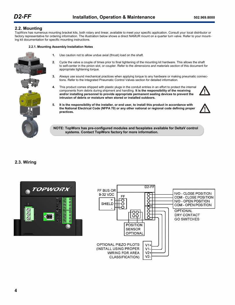
2.2. Mounting TopWorx has numerous mounting bracket kits, both rotary and linear, available to meet your specific application. Consult your local distributor or factory representative for ordering information. The illustration below shows a direct NAMUR mount on a quarter turn valve. Refer to your mount-ing kit documentation for specific mounting instructions. 2.2.1. Mounting Assembly Installation Notes
1. Use caution not to allow undue axial (thrust) load on the shaft.
2. Cycle the valve a couple of times prior to final tightening of the mounting kit hardware. This allows the shaft
to self-center in the pinion slot, or coupler. Refer to the dimensions and materials section of this document for appropriate tightening torque.
3. Always use sound mechanical practices when applying torque to any hardware or making pneumatic connec-tions. Refer to the Integrated Pneumatic Control Valves section for detailed information.
4. This product comes shipped with plastic plugs in the conduit entries in an effort to protect the internal components from debris during shipment and handling. It is the responsibility of the receiving and/or installing personnel to provide appropriate permanent sealing devices to prevent the intrusion of debris or moisture when stored or installed outdoors.
5. It is the responsibility of the installer, or end user, to install this product in accordance with the National Electrical Code (NFPA 70) or any other national or regional code defining proper practices.
2.3. Wiring
NOTE: TopWorx has pre-configured modules and faceplates available for DeltaV control systems. Contact TopWorx factory for more information.

www.topworx.com
®
2.4. Dimensions and Materials Cast aluminum bracket is recommended for installation with SS 8553 valve in vibrating environment.
2.4.1. TopWorx™ DXP
Fastener Torque Specifications
Enclosure Housing Bolts
8 ft.-lbs [10.8 N·m] +/-10%
Indicator Dome Screws
320 in-oz. [2.3 N·m] +/-10%
Bottom Mounting Holes
10 ft.-lbs [13.6 N·m] +/-10%
MATERIALS OF CONSTRUCTION
Enclosure
Cast A360 aluminum with dichromate conversion coating inside & out, epoxy coated exterior rated for 250 hrs. salt spray per ASTM B117
Fasteners 304 Stainless Steel standard 316 Stainless Steel optional
Shaft 304 Stainless Steel standard 316 Stainless Steel optional
Shaft Bushing Oilite Bronze
Indicator Dome Polycarbonate, UV F1 rated
Seals O-ring seals available in: Buna, & Silicone

D2-FF Installation, Operation & Maintenance 502.969.8000
2.4. Dimensions and Materials (Continued)
Cast aluminum bracket is recommended for installation with SS 8553 valve in vibrating environment.
2.4.2. TopWorx™ DXS
Fastener Torque Specifications
Enclosure Housing Bolts
8 ft.-lbs [10.8 N·m] +/-10%
Indicator Dome Screws
320 in-oz. [2.3 N·m] +/-10%
Bottom Mounting Holes
10 ft.-lbs [13.6 N·m] +/-10%
MATERIALS OF CONSTRUCTION
Enclosure Cast 316 Stainless Steel
Fasteners 304 Stainless Steel standard 316 Stainless Steel optional
Shaft 304 Stainless Steel standard 316 Stainless Steel optional
Shaft Bushing N/A
Indicator Dome Polycarbonate, UV F1 rated
Seals O-ring seals available in: Buna
& Silicone,

www.topworx.com
®
2.4. Dimensions and Materials (Continued) Cast aluminum bracket is recommended for installation with SS 8553 valve in vibrating environment.
2.4.3. TopWorx™ DXR
Fastener Torque Specifications
Enclosure Housing Bolts
20 in-lbs [2.3 N·m] +/-10%
Indicator Dome Screws
20 in-oz. [2.3 N·m] +/-10%
Bottom Mounting Holes
8 ft.-lbs [10.8 N·m] +/-10%
MATERIALS OF CONSTRUCTION
Enclosure Valox™ 364
Fasteners 304 Stainless Steel standard 316 Stainless Steel optional
Shaft 304 Stainless Steel standard 316 Stainless Steel optional
Shaft Bushing Delrin™ 500P white
Indicator Dome Polycarbonate, UV F1 rated
Seals Silicone
D2-FF Installation, Operation & Maintenance 502.969.8000
2.4. Dimensions and Materials (Continued)
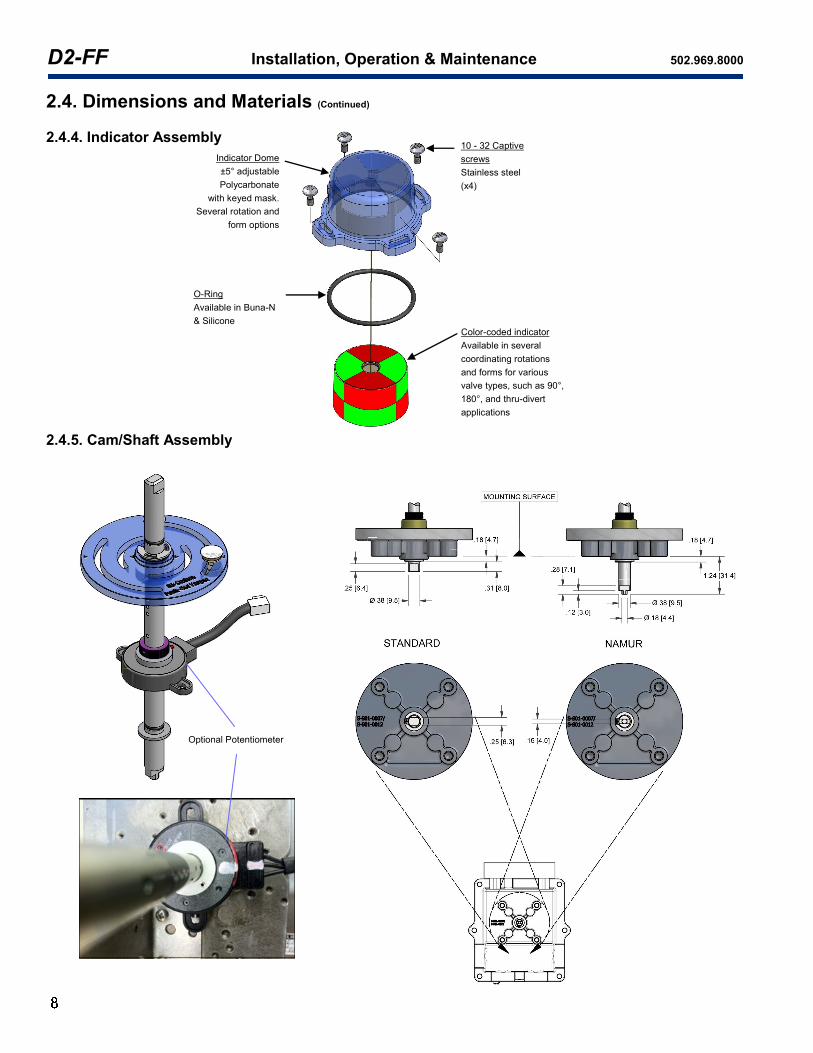
2.4.4. Indicator Assembly 2.4.5. Cam/Shaft Assembly
Indicator Dome
±5° adjustable
Polycarbonate
with keyed mask.
Several rotation and
form options
10 - 32 Captive
screws
Stainless steel
(x4)
O-Ring
Available in Buna-N
& Silicone
Color-coded indicator
Available in several
coordinating rotations
and forms for various
valve types, such as 90°,
180°, and thru-divert
applications
Optional Potentiometer
www.topworx.com
®
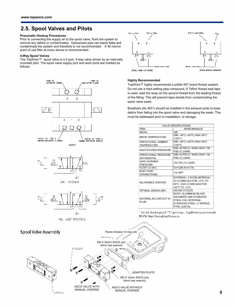
2.5. Spool Valves and Pilots
Pneumatic Hookup Procedures Prior to connecting the supply air to the spool valve, flush the system to remove any debris or contaminates. Galvanized pipe can easily flake and contaminate the system and therefore is not recommended. A 40 micron point of use filter at every device is recommended. 4-Way Spool Valves The TopWorx™ spool valve is a 5 port, 4-way valve driven by an internally mounted pilot. The spool valve supply port and work ports are marked as follows:
Highly Recommended
TopWorx™ highly recommends Locktite 567 brand thread sealant.
Do not use a hard setting pipe compound. If Teflon thread seal tape
is used, start the wrap on the second thread from the leading thread
of the fitting. This will prevent tape shreds from contaminating the
spool valve seals.
Breathers (AL-M31) should be installed in the exhaust ports to keep
debris from falling into the spool valve and damaging the seals. This
must be addressed prior to installation, or storage.
ASCO VALVE WITH MANUAL OVERIDE
ASCO VALVE WITHOUT MANUAL OVERIDE
M5 X 12mm SHCS (x4) (4mm hex wrench)
ADAPTER PLATE
Flame Arrestor O-ring (x4)
M5 X 30mm SHCS (x4) (4mm hex wrench)
D2-FF Installation, Operation & Maintenance 502.969.8000
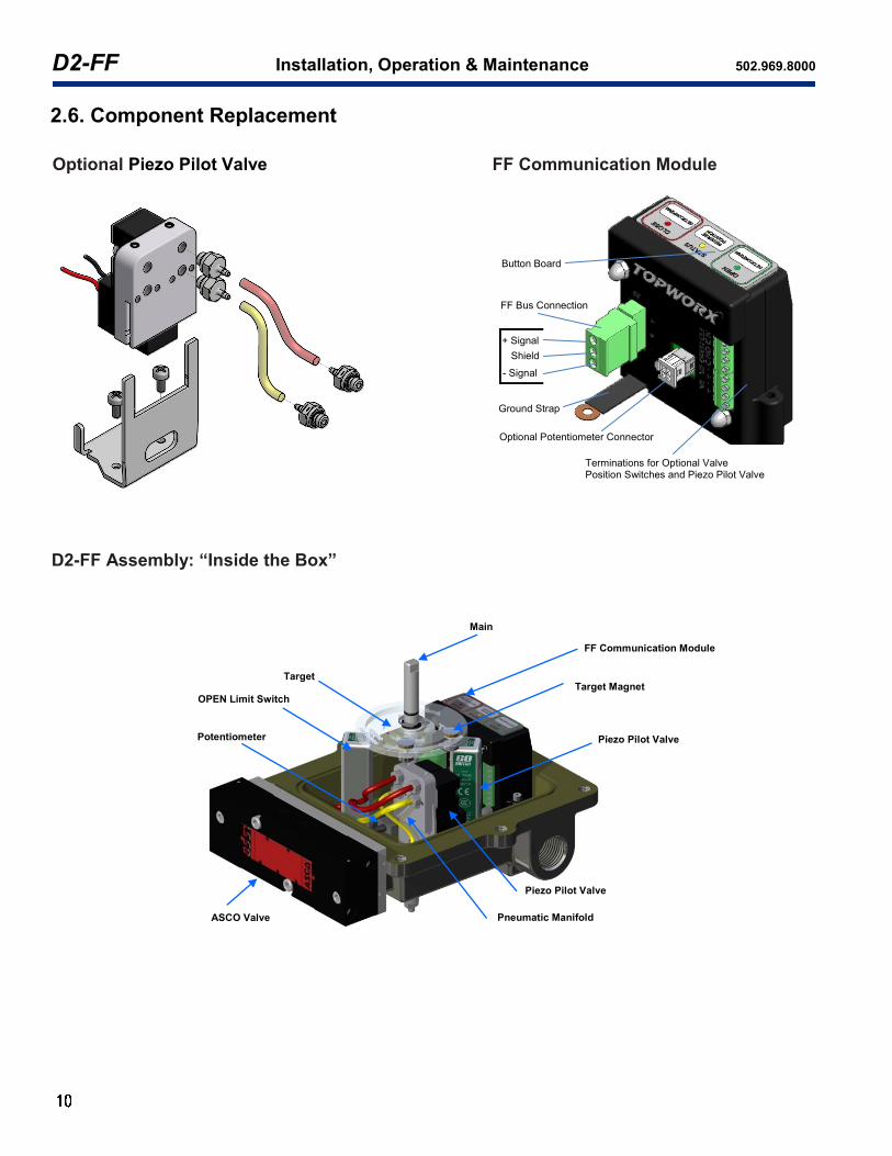
2.6. Component Replacement
Optional Piezo Pilot Valve
Button Board
Terminations for Optional Valve Position Switches and Piezo Pilot Valve
FF Bus Connection
Ground Strap
Optional Potentiometer Connector
+ Signal
Shield
- Signal
FF Communication Module
D2-FF Assembly: “Inside the Box”
ASCO Valve Pneumatic Manifold
Piezo Pilot Valve
Piezo Pilot Valve
Target Magnet
Main
FF Communication Module
OPEN Limit Switch
Potentiometer
Target

www.topworx.com
®
LED Label Off On Blink Flash
STATUS No power Device is calibrated and full functioning
Reversing valve is in process
Calibration is required or error has occurred
CLOSE Not in closed position In closed position Calibrating closed position is in process
Closed GO switch is triggered during calibration
OPEN Not in open position In open position Calibrating open position is in process
Open GO switch
is triggered during calibration
NOTE: LED duty cycle is shown on the right.
Flashing: LED is on for 5% of every second. Blinking: LED is on for 50% of every second.
Function Block Signal Channel Unit
DO Command to open or close 1 None
DI Output command readback 2 None
Open indicator input 3 None
Close indicator input 4 None
AI Instrument temperature 5 ºC
Analog position 6 %
3. Operation This section of the manual provides operational information for configuring, control and monitoring the device locally or remotely through the FOUNDATION Fieldbus Host Control System.
3.1 Operation Mode and Function Block Assignments Automatic (Auto) and Out of Service (OOS) mode are available for all the function blocks in FOUNDATION Fieldbus Host Control System. To operate device using function block, first set the required Function Block mode to OOS, then set the required channel number according to Table 1. After downloading the Function Block to system, set the Function Block mode to AUTO. Note: For DI block, if “Open Indicator Input” is chosen, FIELD_VAL_D parameter will indicate Open/Close status. If “Close Indicator Input” is cho-sen, FIELD_VAL_D parameter will indicate reversed Open/Close status.
Table 1 Function Block Assignments
Table 2 LED Functionality
Table 3 Button Board Functionality
Activity Function
REVERSE button pressed Reverse valve
OPEN button pressed once Start to calibrate open position
OPEN button pressed again Confirm current position as open position
CLOSE button pressed once Start to calibrate closed position
CLOSE button pressed again Confirm current position as closed position
(Section 3 Continued on next page)
on off on off
LED= Flashing LED= Blinking
Time

D2-FF Installation, Operation & Maintenance 502.969.8000
Status Description
Calibration needed Device is not calibrated or calibration for the other end position is needed.
Running Device calibration is in process
Timed Out Device calibration timed out (maximum 5 minutes)
Both triggered Both Go switches are triggered simultaneously
Range error Less than minimum allowed rotation range (minimum 20 degrees)
In deadband End position is too high/low or in deadband
No sensor detected No sensor is detected during calibration
Successful Device is calibrated
3. Operation (Cont.) Table 4 Calibration Statuses
3.2. Device Calibration (Required Configuration) Device can be calibrated either locally using buttons (see section 3.2.1) or remotely using bus command (see section 3.2.2). A summary for LED and button board functionalities is provided in Table 2 and 3.
3.2.1. Calibrating End Positions Locally 3.2.1.1. Perform Calibration
a. This operation is only available if Transducer Block is in OOS mode and the button board is active. If Transducer Block is in Auto mode, change the mode to OOS. If the button board is disabled, set “Buttonboard Enable” parameter to “Active in OOS”.
b. STATUS LED will flash if device is not calibrated. To start calibration procedure, identify the current shaft position by sight, press (greater than 50ms and less than 5min) either the CLOSE or OPEN button according to the position to start the calibration.
c. If CLOSE button is pressed, CLOSE LED will blink to indicate that calibration is in process, perform the following according to sensor type to calibrate the closed end position (note that either CLOSE or OPEN position can be calibrated first): Option #1: GO switch only case: Move magnet to trigger the closed switch (the GO switch labeled as closed position switch). CLOSE LED will flash to indicate the switch is triggered. Option #2: Potentiometer only case: Make sure the potentiometer is not in deadband (the red dot should not fall into the red line area). Option #3: Both GO switch and potentiometer case: Move magnet to trigger the closed switch (the GO switch labeled as closed position switch). CLOSE LED will flash to indicate the switch is triggered. Make sure the potentiometer is not in deadband (the red dot should not fall into the red line area). * Press the CLOSE button AGAIN to confirm the position. CLOSE LED will become solid on.
d. Press the REVERSE button (greater than 50ms and less than 5min) to move valve to the other position. If there is a potentiometer, as the shaft rotates, make sure the potentiometer is not rotating through its deadband area. STATUS LED will blink for 3 seconds to indi-cate the reverse action. Note: The REVERSE button is not operational in units without integral pilot valves supplied by TopWorx. For those applications, the valve will have to be moved manually or with existing controls.
e. Press the OPEN button and perform the following according to sensor type to calibrate the open end position (note that these steps are similar to the calibration for the closed end position): Option #1: GO switch only case: Move magnet to trigger the open switch (the GO switch labeled as open position switch). OPEN LED will flash to indicate the switch is triggered. Option #2: Potentiometer only case: Make sure the potentiometer is not in deadband. Option #3: Both GO switch and potentiometer case: Move magnet to trigger the open switch (the GO Switch labeled as open position switch). OPEN LED will flash to indicate the switch is triggered. Make sure the potentiometer is not in deadband. * Press the OPEN button AGAIN to confirm the position. OPEN LED will become solid on.
f. STATUS LED will become solid on if the calibration procedure is successful. It will flash if the calibration is failed. The calibration sta-tus will be shown in “Calibration Status”. Please see Table 4 for the list of calibration statuses.
Note that either end position can be re-calibrated/re-adjusted if the other end position is already calibrated. That is, after initial calibration, either position can be recalibrated individually without calibrating the other position.
3.2.2. Calibrating End Positions Remotely Calibration remotely using bus command can be done through guided method (For example, from AMS or Handheld screens, see section 3.2.2.1) or manual setup (see section 3.2.2.2).
3.2.2.1. Perform Guided Calibration through Method (Recommended) Click the method “Device Setup” or “Calibrate” on screen and follow the instructions for calibration.
3.2.2.2. Perform Calibration by Setting Parameters a. This operation is only available if the Transducer Block is in OOS mode. If Transducer Block is in Auto mode, change the
mode to OOS.
(Section 3 Continued on next page)
Deadband Indication

www.topworx.com
®
3. Operation (Cont.) b. STATUS LED will flash if device is not calibrated. To start calibration procedure, select the “Set to current position” from either the
“Open End Position” or the “Close End Position” parameter. The corresponding OPEN or CLOSE LED will blink to indicate that cali-bration is in process.
c. For calibrating the “Close End Position”, perform the following according to sensor type to calibrate the closed end position (note that either the “Open End Position” or the “Close End Position” can be calibrated first): Option #1: GO switch only case: Move magnet to trigger the closed switch (the GO switch labeled as closed position switch). CLOSE LED will flash to indicate the switch is triggered. Option #2: Potentiometer only case: Make sure the potentiometer is not in deadband (the red dot should not fall into the red line area). Option #3: Both GO switch and potentiometer case: Move magnet to trigger the closed switch (the GO Switch labeled as closed position switch). CLOSE LED will flash to indicate the switch is triggered. Make sure the potentiometer is not in deadband (the red dot should not fall into the red line area).
* The status for “Close End Position” will automatically change back to “No Action Required” if the action is performed. d. Select the “Reverse” from the “Reverse Valve Position” parameter. If there is a potentiometer, as the shaft rotates, make sure the
potentiometer is not rotating through its deadband area. STATUS LED will blink for 3 seconds to indicate the reverse action. Note: The REVERSE button and "Reverse Valve Position" is not operational in units without integral pilot valves supplied by TopWorx. For those applications, the valve will have to be moved manually or with existing controls.
e. Select the “Set to current position” from the “Open End Position”. (note that these steps are similar to the calibration for the closed end position): Option #1: GO switch only case: Move magnet to trigger the open switch (the GO switch labeled as open position switch). OPEN LED will flash to indicate the switch is triggered. Option #2: Potentiometer only case: Make sure the potentiometer is not in deadband. Option #3: Both GO switch and potentiometer case: Move magnet to trigger the open switch (the GO switch labeled as open position switch). OPEN LED will flash to indicate the switch is triggered. Make sure the potentiometer is not in deadband.
* The status for “Open End Position” will automatically change back to “No Action Required” if the action is performed. f. STATUS LED will become solid on if the calibration procedure is successful. It will flash if the calibration failed. The calibration status
will be shown in “Calibration Status”. Please see Table 4 for the list of status. *Note that either end position can be re-calibrated/re-adjusted if the other end position is already calibrated.
3.3. End Position Deadband Adjustment If there is a potentiometer, the end position deadband is determined by the value for “Open/Close Stop Offset” parameter. This value is adjustable. Its default value is 10% and the allowable range is 5% to 40%. For example, with the default value, if the open position is at 100 degree and the closed position is at 50 degree, then if actual value position is within 50±(100-50)×10%=45~55 degree, the “Close State” is “True”, and the “Open State” is “False”.
3.4. Reverse Valve Position Valve position can be reversed locally by pressing the REVERSE button on the button board if it is enabled. It can also be done remotely by select-ing the “Reverse” from the “Reverse Valve” parameter when device is in OOS mode. The value for “Reverse Valve” will automatically change back to “No action” (default value) if the action is performed. STATUS LED will blink for 3 seconds to indicate the reverse action. Note: The REVERSE button is not operational in units without integral pilot valves supplied by TopWorx. For applications, the valve will have to be moved manually or with existing controls.
3.5. Flash LED To identify a device in the plant, put Transducer Block into OOS mode and select the “Flash LED” for the “Flash LED” parameter. Status LED on the unit will blink for 5 minutes. After 5 minutes, status for “Flash LED” will automatically change back to “Finished” (default value).
3.6. Shutdown Configuration Shutdown configuration controls the behavior of the valve in case of an internal communications failure in the electrical module. This is independent of the FF communication on the bus line. The “shutdown action” parameter is also re-used as the default position (initial status) for a device encoun-tered a power loss. 3.6.1. Parameters and functions
a. Shutdown enable (SHUTD_ENABLE parameter): Enable, auto recovery: If there is an internal failure, valve will move to certain position according to the setting of parameter SHUTDOWN_ACTION. When the internal failure is solved, the valve will automatically go to its current setpoint position. Enable, manual recovery: If there is an internal failure, valve will move to certain position according to the setting of parameter SHUTDOWN_ACTION. When the internal failure is solved, the valve will NOT automatically go to its current setpoint position unless SHUTD_RESET parameter is manually selected as “reset”. Disable: Shutdown functionality is not operational; the valve will stay in its last position after an internal failure.
b. Shutdown action (SHUTD_ACTION parameter): Open: When performing shutdown operation or starting up after a power loss, valve will go to open position. Close: When performing shutdown operation or starting up after a power loss, valve will go to close position. Hold: When performing shutdown operation or starting up after a power loss, valve will stay in original position. Note: The shutdown action is not operational in units without integral pilot valves supplied by TopWorx. For those applications, the valve will have to be moved manually or with existing controls.
c. Shutdown delay (SHUTD_DELAY_TIME parameter): The time waited to perform shutdown operation after the internal failure occurs. The default value is 5 seconds. The allowable range is from 2 to 255 seconds.
(Section 3 Continued on next page)

D2-FF Installation, Operation & Maintenance 502.969.8000
3. Operation (Cont.)
d. Shutdown reset (SHUTD_RESET parameter): Inactive: Shutdown reset function is not active. If “manual recovery” is selected for SHUTD_ENABLE parameter and there is an internal error, after the internal failure is solved, the valve will NOT automatically go to its current setpoint position. Device stays in shutdown status. Reset: Shutdown reset function is active. If “manual recovery” is selected for SHUTD_ENABLE parameter and there is an internal error, after the internal failure is solved, shutdown status will be reset, and the valve will automatically go to its current setpoint position. When this reset is completed, the SHUTD_STATUS parameter will be “Device is operational” and the SHUTD_RESET parameter will return to “inactive”.
e. Shutdown status (SHUTD_STATUS parameter): Device operational: there is no internal error. Device shutdown: there is internal error.
3.6.2. Examples
a. For internal communications failure The factory default shutdown configuration settings are as following: Shutdown enable: Enable, Manual Recovery Shutdown action: Close Shutdown delay: 5 seconds Shutdown reset: Inactive If there is an internal failure, after 5 seconds, valve will move to close position according to the setting of parameter SHUTDOWN_ACTION. When the internal failure is solved, the valve will NOT automatically go to its current setpoint position unless SHUTD_RESET parameter is manually selected as “reset”.
b. For power lose If the “shutdown action” is “Open”, when power is re-applied to device after a power loss, before valve receives the bus command (for example, the SP_D from DO function block), valve will go to open position. If the “shutdown action” is “Hold”, when power is re-applied to device after a power loss, before valve receives the bus command (for example, the SP_D from DO function block), valve will stay in the previous position, that is, the position that power is off.
3.7. Buttonboard Enable Local operation through push buttons is only available when the button board is active. The factory default value for “Buttonboard Enable” parameter is “Active in OOS”. When device is in OOS mode, the button board can be enabled by setting the “Buttonboard Enable” parameter to “Active in OOS” or disabled by setting it to “Never active”.
3.8. Valve Position Indication The “Analog position” parameter will indicate current valve position in percentage (the display range for AI block: -200% to +199%, the display range for TB block: 0%~100%) if there is a potentiometer and the calibration is successful, otherwise, the value is 0. The percentage is calculated as the distance in degrees from current position to close position versus the full open to close distance in degrees. The “Final Discrete Position” parameter will indicate current valve position as “Closed”, “Open”, “Opening” or “Closing”. Device will indicate “Closed” or “Open” according to the discrete position. The assigned position from DO block is indicated by “DO Command” parameter as “Close” or “Open”.
3.9. Position Sensor Type Indication The “Position Sensor Type” parameter will indicate the sensor type detected by the device during calibration. This parameter will indicate “GO switch only”, “Potentiometer only”, or “Both GO switch and potentiometer” if sensor type is detected. Otherwise, it will indicate “Not assigned” (default value).
3.10. Temperature Indication Temperature is measured every 100 millisecond by the sensor on the circuit board and indicated as degree C by “Temperature” parameter. The allowed temperature range is -25 to +65 degree C. An alarm will be triggered if temperature is out of range (Please see the Alert section for more details). The maximum/minimum measured temperature is recorded in the device. It can be viewed through the command in base record.
3.11. Device Cycle Count, Adjustment and Control The parameter “Cycle Count” (this parameter is read only) indicates the total end position cycles. The parameter “Adjusted Count” indicates the end position cycles after adjustment. If valve position changes from close to open and back to close, the value for both parameters will be increased by one. Users can set “Adjusted Count” to any non-negative value and the adjusted cycle count will start to increase based on this set value. Users can set a limit for them using the “Cycle Count Limit” and “Adjusted Count Limit” parameters. The default limit is 1000000 cycles. The allowed input value for “Cycle Count Limit” must be greater than the current cycle count and less than 4294967296. The allowed input value for “Adjusted Count Limit” must be greater than the current adjusted cycle count and less than 4294967296. An alarm will be triggered if the count is out of range limit (Please see the Alert section for more details).
3.12 Timers There are 3 timers available in this device: Time in position: the time in seconds that device is in current position since the last movement. It is automatically reset to zero when the power is switched off. Open travel time: the time between when pilot valve position is changed due to request and when the open end position is reached. It is indicated in seconds with accuracy in 10 milliseconds. Close travel time: the time between when pilot valve position is changed due to request and when the close end position is reached. It is indicated in seconds with accuracy in 10 milliseconds.
(Section 3 Continued on next page)
www.topworx.com
®
3. Operation (Cont.) These values are important in determining abnormal events that recently occurred. For example, a temporary drop in pressure or a sticky process valve (valve that has been left in the same position for a long time without cycling) will affect the performance of the last operation of the valve, but does not necessarily mean the mechanical device is worn out. The average open/close travel time (in seconds) of the last 30 strokes is calculated and indicated in parameter “Average Time”. Process valve/actuators typically wear out at a constant steadily pace. A good indication of wear will be the average travel times since the change is slow, but constant. Users can set an upper limit for “Time in position” using the “Time in Position Hi Limit” parameter. The default value is 864000 seconds (10 days). The allowed input value must be less than 4294967296. Users can also set the low/high limits for the open/close travel time and the average open/close travel time using their “Travel Lo Limit” and “Travel Hi Limit” parameters. The default value is 0 for the low limit and 300 seconds for the high limit. The allowed input value must be less than 65536. An alarm will be trig-gered if any time value is out of range limit (Please see the Alert section for more details).
3.13 Field Diagnostic Alerts/Plantweb Alerts 3.13.1. List of Alerts
Check: The Check condition is true if any transducer block has a normal mode other than Out of Service and the actual mode is not AUTO. Calibration Failed: Device has not been calibrated or the calibration has failed. Please refer to Table 4 Calibration Statuses for the reason of failure. Bad Temperature Sensor: Temperature sensor is malfunctioning. Temperature value is not reliable. System Temperature Exceeded: Maximum/minimum temperature exceeds the value set in the limit. Software Error: Controller card memory error occurs. Travel Deviation:
a. Valve/actuator moves to an undesired position. For example, the device energizes an output to OPEN a spring return actuator. The position feedback indicates the device has reached the OPEN position. Afterwards, air pressure is lost and the actuator moves back to the CLOSED position (spring-return). The position feedback sensor will indicate the actuator is in the CLOSED position although a command to CLOSE the actuator has never been issued. In this situation a Travel Deviation alert will be generated indicating the actuator was in a desired position, but moved to an undesired position.
b. Valve/actuator doesn’t move to a desired position. For example, the device energizes an output to OPEN a spring return actuator. But the air pressure is lost so the actuator doesn’t move. After 5 minutes, the position feedback indicates the device still has not reached the OPEN position. Travel Deviation alert will be generated indicating the actuator can not move to a desired position.
Shutdown is Set: Device shutdown is operating due to an internal communications failure in the electrical module. Buttonboard Failure: Button board is malfunctioning. Open/Short Circuit: There is an open circuit for the main Piezo or there is a short circuit for any Piezos. If there is an open circuit or the main Piezo, only this alert is triggered. Device will automatically operate as normal once there is no open circuit for the main Piezo. If there is a short circuit for any Piezos, device will power off both Piezos. Device will return to normal Piezo operation only if no short circuit is detected after a power cycle. Adjusted Cycle Count Exceeded: Adjusted cycle count has exceeded the value set in the limit. Control Module Life Cycle Exceeded: Cycle count has exceeded the value set in the limit. Time in Position Limit Exceeded: Time value has exceeded the value set in the limit. Open Travel Time Limit Exceeded: Time value has exceeded the value set in the limit. Close Travel Time Limit Exceeded: Time value has exceeded the value set in the limit. Internal I/O Failure: Internal communications are lost; device will act according to shutdown configuration. NV Memory Failure: Non-volatile EEPROM data corruption was detected on the Fieldbus electronics board. Default values were loaded into the faulty block. If the failure reoccurs it may indicate a faulty EEPROM memory chip. Electronics Failure: The device has detected a fault with an electrical component on the Fieldbus electronics module assembly. Note: The Travel Deviation and Open/Short Circuit Alerts are not monitored in units without integral pilot valves supplied by TopWorx. For those applications, the valve will have to be moved manually or with existing controls.
3.13.2. Alert handling Both field diagnostics and PlantWeb alerts are supported in this device. Although these alerts have default settings (see table 5), these can be changed by the customer to match their requirements. For field diagnostic alerts, there are four levels of alerts available:
a. Failed Alerts A Failure Alert indicates a failure within a device that will make the device or some part of the device non-operational. This implies that the device is in need of repair and must be fixed immediately. This alert has the following five parameters: FD_FAIL_MAP: Enables or disables conditions to be detected as active for this alarm category. Thus the same condition may be active in all, some, or none of the alarm categories. FD_FAIL_MASK: allows the user to suppress any single or multiple conditions that are active, in this category, from being broadcast to the host through the alarm parameter. FD_FAIL_PRI: Designates the priority. FD_FAIL_ACTIVE: Reflects the error conditions that are being detected as active as selected for this category. Multiple conditions may be shown. FD_FAIL_ALM: To report the particular failed condition to the host system.
(Section 3 Continued on next page)

D2-FF Installation, Operation & Maintenance 502.969.8000
3. Operation (Cont.)
b. Off Spec Alerts An Off Spec Alert indicates a condition within a device that is out of the range of the specification. The alert is used to notify the host that the device has detected a condition within the device that is not critical, will not cause a failure if left unat-tended but should be reported to the host for awareness and possible action. This alert has the following five parameters: FD_OFFSPEC_MAP: Enables or disables conditions to be detected as active for this alarm category. Thus the same condi-tion may be active in all, some, or none of the alarm categories. FD_OFFSPEC_MASK: allows the user to suppress any single or multiple conditions that are active, in this category, from being broadcast to the host through the alarm parameter. FD_OFFSPEC_PRI: Designates the priority. FD_OFFSPEC_ACTIVE: Reflects the error conditions that are being detected as active as selected for this category. Multiple conditions may be shown. FD_OFFSPEC_ALM: To report the particular failed condition to the host system.
c. Maintenance Alerts A Maintenance Alert indicates a condition within a device that, if not attended to in the near future (the type of alert defines the time period for “Near Future”) will make the device or some part of the device non-operational. This implies that the de-vice is in need of repair and must be fixed as soon as possible. This alert has the following five parameters: FD_MAINT_MAP: Enables or disables conditions to be detected as active for this alarm category. Thus the same condition may be active in all, some, or none of the alarm categories. FD_MAINT_MASK: allows the user to suppress any single or multiple conditions that are active, in this category, from being broadcast to the host through the alarm parameter. FD_MAINT_PRI: Designates the priority. FD_MAINT_ACTIVE: Reflects the error conditions that are being detected as active as selected for this category. Multiple conditions may be shown. FD_MAINT_ALM: To report the particular failed condition to the host system.
d. Check Alerts A Check Alert indicates output signal temporarily invalid (e.g. frozen) due to on-going work on the device. This alert has the following five parameters: FD_CHECK_MAP: Enables or disables conditions to be detected as active for this alarm category. Thus the same condition may be active in all, some, or none of the alarm categories. FD_CHECK_MASK: allows the user to suppress any single or multiple conditions that are active, in this category, from being broadcast to the host through the alarm parameter. FD_CHECK_PRI: Designates the priority. FD_CHECK_ACTIVE: Reflects the error conditions that are being detected as active as selected for this category. Multiple conditions may be shown. FD_CHECK_ALM: To report the particular failed condition to the host system.
For Plantweb alerts, there are three levels of alerts available:
a. Failed Alerts
A Failure Alert indicates a failure within a device that will make the device or some part of the device non-operational. This implies that the device is in need of repair and must be fixed immediately. This alert has the following five parameters: FAILED_ENABLE: Enable the indication and reporting. FAILED_MASK: Suppress reporting. FAILED_PRI: Designates the priority. FAILED_ACTIVE: Displays which of the conditions within the alert is active. FAILED_ALM: To report the particular failed condition to the host system.
b. Maintenance Alerts A Maintenance Alert indicates a condition within a device that, if not attended to in the near future (the type of alert defines the time period for “Near Future”) will make the device or some part of the device non-operational. This implies that the de-vice is in need of repair and must be fixed as soon as possible. This alert has the following five parameters: MAINT_ENABLE: Enable the indication and reporting. MAINT_MASK: Suppress reporting. MAINT_PRI: Designates the priority. MAINT_ACTIVE: Displays which of the conditions within the alert is active. MAINT_ALM: To report the particular failed condition to the host system.
c. Advisory Alerts An Advisory Alert indicates a condition within a device that is informational in nature. The alert is used to notify the host that the device has detected a condition within the device that is not critical, will not cause a failure if left unattended but should be reported to the host for awareness and possible action. This alert has the following five parameters: ADVISE_ENABLE:Enable the indication and reporting. ADVISE_MASK: Suppress reporting. ADVISE_PRI: Designates the priority. ADVISE_ACTIVE: Displays which of the conditions within the alert is active. ADVISE_ALM: To report the particular failed condition to the host system.
(Section 3 Continued on next page)

www.topworx.com
®
3. Operation (Cont.) 3.13.3. Alert parameter description
a. Alerts – Enable/Map These parameters are used to enable the indication and reporting of each corresponding alert. When an alert is disabled, the device shall not detect that particular alert; it shall not be indicated in the xxxx_ACTIVE parameters or be reported via respectively alerts. If an alert enable parameter is changed to “disabled” while the alert is active, it shall clear the alert and re-evaluate the alert.
b. Alerts - Mask These parameters will mask any of the failed conditions listed in respectively alerts. Setting a bit to true will cause the corresponding alert to be indicated in the xxxx_ACTIVE parameters but not reported to the host via the alerts. If an alert mask is changed while the alert is active, the alert is cleared and all the conditions are reevaluated.
c. Alerts - Priority This designates the priority of the alerts. The default is 0 and the recommended value is between 10 and 15. If left as initial value, no alerts will be delivered to the HOST.
d. Alerts - Active These parameters display which of the conditions is active. When a device detects a condition has become active, it shall set the corresponding bit in the xxxx_ACTIVE parameters. If it is not suppressed/masked, it will be reported using the associated alert pa-rameter. These parameters are read only.
e. Alerts - Alarm These parameters are used to report the particular condition to the host. These parameters are read only.
3.13.4. Recommended Actions and Default Settings for Alerts. Please see the Table 5 below for the recommended actions and default
settings for all alerts. Note: Enabling/disabling and masking for PlantWeb Alerts follow the NAMUR Field Diagnostics alerts and are not independent. However, the alarm priorities are independent such that it is possible to get "double" or no alerts.
Table 5 Recommended Actions and Default Setting/Mapping for Alerts (Note that no alert is masked in factory default settings)
Alerts
Recommended Actions
Default Enabled Alert
Field Diagnostic Plantweb
Failed Off Spec Maint. Check Failed Maint. Advisory
Check Check transducer block mode.
Calibration Failed
Calibration required or failed, check calibration status for reasons, check air pressure, check valve system, re-calibrate valve controller.
Bad Temperature Sensor Temperature sensor is not functioning, replace valve controller when possible.
System Temperature Exceeded
Temperatures too high/low, take cor-rective actions to bring temperature within specified range.
Software Error Software error detected, cycle power, if problem persists, replace valve control-ler when possible.
Travel Deviation
Lost position, check air pressure, check shaft assembly and position, check open/close go switch and/or potentiom-eter connection if available.
Shutdown is Set
Internal communications problem, check shutdown configuration for re-start, if problem persists after restart, replace valve controller when possible.
Buttonboard Failure
Button board is not functioning correct-ly, replace valve controller when possi-ble.
Open or Short Circuit
Output to pilot valve disabled because of open/short circuit, check pilot valve connection. Replace malfunctioning Piezo. When short circuit issue is re-solved, device must be power cycled.
Adjusted Cycle Count Exceeded
Adjusted cycle counter exceeded limit, re-assign limit or re-adjust cycle count.
(Section 3 Continued on next page)

D2-FF Installation, Operation & Maintenance 502.969.8000
3. Operation (Cont.) Table 5 Recommended Actions and Default Setting/Mapping for Alerts (Cont.) (Note that no alert is masked in factory default
settings)
(Table 5 Continued on next page)
Alerts
Recommended Actions
Default Enabled Alert
Field Diagnostic Plantweb
Failed Off Spec Maint. Check Failed Maint. Advisory
Control Module Life Cycle Exceeded
Valve controller life cycle exceeded limit, replace valve controller. Recom-mend complete switchbox replace-ment.
Time in Position Limit Ex-ceeded
Time in position exceeded, check control system configuration, and check valve and valve actuator.
Open Travel Time Limit Ex-ceeded
Open travel timer exceeded, check air pressure, check shaft assembly and position, check open/close go switch and/or potentiometer connection if available.
Close Travel Time Limit Ex-ceeded
Close travel timer exceeded, check air pressure, check shaft assembly and position, check open/close go switch and/or potentiometer connection if available.
Internal I/O Failure
Internal communications are lost; valve controller will act according to shutdown configuration. If problem persists, replace valve controller when possible.
NV Memory Failure
Non-volatile EEPROM data corruption was detected on the Fieldbus Elec-tronics Board. Default values were loaded into the faulty block. 1. Check the device configuration for changes in the block parameter val-ues. 2. Reset the processer to clear the error. 3. Download a Device Configuration. NOTE: If the failure reoccurs it may indicate a faulty EEPROM memory chip.
Electronics Failure
The valve controller has detected a fault with an electrical component on the Fieldbus Electronics Module As-sembly. Replace the valve controller.
www.topworx.com
®
3. Operation (Cont.)
3.14. Restart Methods You can restart the module via different mechanisms. Depending on which restart option is used; the communication links, static parameters, etc. may be affected. However, due to the effect that a restart can have on the module, and therefore the process, restarting the module should be used cautiously.
3.14.1. Restart using bus command There are several Restart options as described bellow. This can be done via parameter RESTART in the Resource block. The following is a brief description for each of the restart options:
a. Resource Performing a “Resource”-restart resets the dynamic variables in the Function Blocks but has no observable effect on the module. However, the dynamic variable within the module are reset and this could cause a “bump” in your process.
b. Defaults Performing a “Restart with Defaults” should be done with care. This restart sets the static parameters of the function blocks in the module to their default state. It also disconnects all links within the module. After performing a “Restart with Defaults”, a “Restart Processor” should be performed.
c. Processor Performing a “Restart Processor” has the same effect as removing power from the module and re-applying power. This is typically used to restart the module if device shutdown is set due to internal communication lost caused by incorrect power application.
d. Valve Controller Processor Performing a “Valve Controller Processor”-Restart has the same effect as removing power from the module and re-applying power. This is typically used to restart the control part of the module.
e. Valve Controller Defaults Performing a “Valve Controller Defaults”-restart should be done with care. This restart sets the calibration to default. It will erase the calibration information. It has the same effect as “restart locally using buttons” in the following subsection.
f. Restore Factory Default Blocks Performing “Restore Factory Default Blocks” restores default blocks i.e. manufacturer pre-instantiated blocks. It will clear complete NV memory of device and this will result in NV Memory Failure error. To clear this error in device, a “Restart Processor” should be performed.
3.14.2. Restart locally using buttons To set valve controller to factory default locally using buttons: power off device, push both OPEN and CLOSE buttons, power on device, release buttons when status LED is on.
3.15. Device Options 3.15.1. Enable/disable field diagnostics alerts simulation
This method will enable/disable field diagnostics alerts simulation. 3.15.2. Enable/disable access to the TB base record parameter
This method will enable/disable access to the Transducer Block base record parameter.
3.16. Base Record Methods 3.16.1. Get current real position: get position in percentage. 3.16.2. Get open endpoint: Get open endpoint in degrees. Due to 18 degrees dead band, the range is from 0 to 341. 3.16.3. Get close endpoint: Get close endpoint in degrees. 3.16.4. Get minimum temperature ever in degree C. 3.16.5. Get maximum temperature ever in degree C.
3.17. DD Version Info This method will show the build number, date and info for the device description files.
(Section 3 Continued on next page)

D2-FF Installation, Operation & Maintenance 502.969.8000
3. Operation (Cont.)
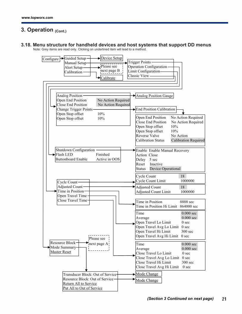
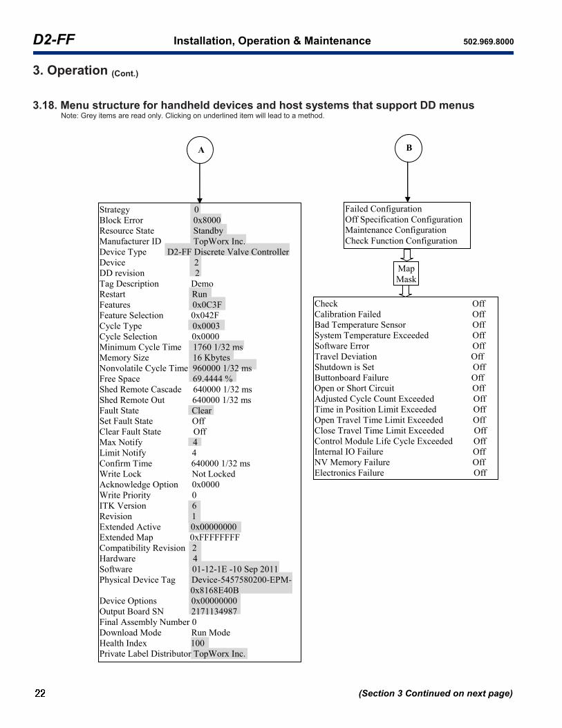
3.18. Menu structure for handheld devices and host systems that support DD menus Note: Grey items are read only. Clicking on underlined item will lead to a method.
(Section 3 Continued on next page)
Device Type D2-FF Discrete Valve Controller
Device 2
DD Revision 2
ITK version 6
Output Board SN 2171134987
Hardware 4
Software 01-12-1E -10 Sep 2011
Control Card SW 1.3
Identification
Revisions
Calibration Information
Security and Simulation
Instrument Temperature
Analog Position
Value Closed
Cycle Count 18
Adjusted Count 18
Position Sensor Type GO Switches Only
Time in Position 697 sec
Open Travel
Close Travel
All Mode Toggle
Overview Device Status: Good
Mode:Out of service
Analog Position 0%
DO Command Closed
Final Discrete Position Closed
Variables
Device Information
Instrument Temperature Gauge
Analog Position Gauge
Time 0.000 sec
Average 0.000 sec
Time 0.000 sec
Average 0.000 sec
Model Number 0200
Serial Number 0001
Calibration Status Calibration required
Location Louisville
Date 09/10/2011 12:13:14
Performed by TopWorx
Write Lock Not Locked
Simulate Enable/Disable Disabled
Device Options
www.topworx.com
®
3. Operation (Cont.)
3.18. Menu structure for handheld devices and host systems that support DD menus Note: Grey items are read only. Clicking on underlined item will lead to a method.
(Section 3 Continued on next page)
Device Setup
Analog Position
Open End Position No Action Required
Close End Position No Action Required
Change Trigger Points
Open Stop offset 10%
Open Stop offset 10%
Analog Position Gauge
Shutdown Configuration
Flash LED Finished
Buttonboard Enable Active in OOS
End Position Calibration
Open End Position No Action Required
Close End Position No Action Required
Open Stop offset 10%
Open Stop offset 10%
Reverse Valve No Action
Calibration Status Calibration Required
Trigger Points
Operation Configuration
Limit Configuration
Classic View Calibrate
Configure Guided Setup
Manual Setup
Alert Setup
Calibration
Please see next page B
Enable Enable Manual Recovery
Action Close
Delay 5 sec
Reset Inactive
Status Device Operational
Cycle Count 18
Cycle Count Limit 1000000
Adjusted Count 18
Adjusted Count Limit 1000000
Time in Position 8888 sec
Time in Position Hi Limit 864000 sec
Time 0.000 sec
Average 0.000 sec
Open Travel Lo Limit 0 sec
Open Travel Avg Lo Limit 0 sec
Open Travel Hi Limit 300 sec
Open Travel Avg Hi Limit 0 sec
Time 0.000 sec
Average 0.000 sec
Close Travel Lo Limit 0 sec
Close Travel Avg Lo Limit 0 sec
Close Travel Hi Limit 300 sec
Close Travel Avg Hi Limit 0 sec
Cycle Count
Adjusted Count
Time in Position
Open Travel Time
Close Travel Time
Transducer Block: Out of Service
Resource Block: Out of Service
Return All to Service
Put All to Out of Service
Mode Change
Mode Change
Resource Block
Mode Summary
Master Reset
Please see
next page A
D2-FF Installation, Operation & Maintenance 502.969.8000
3. Operation (Cont.)
3.18. Menu structure for handheld devices and host systems that support DD menus Note: Grey items are read only. Clicking on underlined item will lead to a method.
Map
Mask
Check Off
Calibration Failed Off
Bad Temperature Sensor Off
System Temperature Exceeded Off
Software Error Off
Travel Deviation Off
Shutdown is Set Off
Buttonboard Failure Off
Open or Short Circuit Off
Adjusted Cycle Count Exceeded Off
Time in Position Limit Exceeded Off
Open Travel Time Limit Exceeded Off
Close Travel Time Limit Exceeded Off
Control Module Life Cycle Exceeded Off
Internal IO Failure Off
NV Memory Failure Off
Electronics Failure Off
Failed Configuration
Off Specification Configuration
Maintenance Configuration
Check Function Configuration
Strategy 0
Block Error 0x8000
Resource State Standby
Manufacturer ID TopWorx Inc.
Device Type D2-FF Discrete Valve Controller
Device 2
DD revision 2
Tag Description Demo
Restart Run
Features 0x0C3F
Feature Selection 0x042F
Cycle Type 0x0003
Cycle Selection 0x0000
Minimum Cycle Time 1760 1/32 ms
Memory Size 16 Kbytes
Nonvolatile Cycle Time 960000 1/32 ms
Free Space 69.4444 %
Shed Remote Cascade 640000 1/32 ms
Shed Remote Out 640000 1/32 ms
Fault State Clear
Set Fault State Off
Clear Fault State Off
Max Notify 4
Limit Notify 4
Confirm Time 640000 1/32 ms
Write Lock Not Locked
Acknowledge Option 0x0000
Write Priority 0
ITK Version 6
Revision 1
Extended Active 0x00000000
Extended Map 0xFFFFFFFF
Compatibility Revision 2
Hardware 4
Software 01-12-1E -10 Sep 2011
Physical Device Tag Device-5457580200-EPM-
0x8168E40B
Device Options 0x00000000
Output Board SN 2171134987
Final Assembly Number 0
Download Mode Run Mode
Health Index 100
Private Label Distributor TopWorx Inc.
B A
(Section 3 Continued on next page)

www.topworx.com
®
3. Operation (Cont.)
3.18. Menu structure for handheld devices and host systems that support DD menus Note: Grey items are read only. Clicking on underlined item will lead to a method.
Service Tools Alerts
Variables
Trends
Maintenance
Simulate
Active Alerts Device Status: Good
Instrument Temperature
Analog Position
Value Closed
Cycle Count 18
Adjusted Count 18
Position Sensor Type GO Switches Only
Time in Position 697 sec
Open Travel
Close Travel
Instrument Temperature Gauge
Analog Position Gauge
Time 0.000 sec
Average 0.000 sec
Time 0.000 sec
Average 0.000 sec
Analog Position
Instrument Temperature
Trend
Analog Position 0 %
Analog Position Trend
Trend
Instrument Temperature 19 ºC
Instrument Temperature Trend
Calibrate
Simulate Enable/Disable Disabled
Device Options
Simulate Alerts
Check Off
Calibration Failed Off
Bad Temperature Sensor Off
System Temperature Exceeded Off
Software Error Off
Travel Deviation Off
Shutdown is Set Off
Buttonboard Failure Off
Open or Short Circuit Off
Adjusted Cycle Count Exceeded Off
Time in Position Limit Exceeded Off
Open Travel Time Limit Exceeded Off
Close Travel Time Limit Exceeded Off
Control Module Life Cycle Exceeded Off
Internal IO Failure Off
NV Memory Failure Off
Electronics Failure Off
(Section 3 Continued on next page)
D2-FF Installation, Operation & Maintenance 502.969.8000
3. Operation (Cont.)
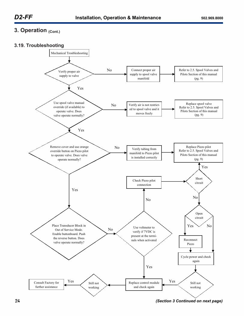
3.19. Troubleshooting
(Section 3 Continued on next page)
Yes
No
Cycle power and check
again
Yes
Yes
No
No
Verify proper air
supply to valve
Mechanical Troubleshooting
Connect proper air
supply to spool valve
manifold
Refer to 2.5. Spool Valves and
Pilots Section of this manual
(pg. 9)
No
Yes
Use spool valve manual
override (if available) to
operate valve. Does
valve operate normally?
Place Transducer Block in
Out of Service Mode.
Enable buttonboard. Push
the reverse button. Does
valve operate normally?
Verify air is not restrict-
ed to spool valve and it
moves freely
Replace spool valve
Refer to 2.5. Spool Valves and
Pilots Section of this manual
(pg. 9)
Remove cover and use orange
override button on Piezo pilot
to operate valve. Does valve
operate normally?
Verify tubing from
manifold to Piezo pilot
is installed correctly
Replace Piezo pilot
Refer to 2.5. Spool Valves and
Pilots Section of this manual
(pg. 9)
Consult Factory for
further assistance
Replace control module
and check again
Use voltmeter to
verify if 7VDC is
present at the termi-
nals when activated
Check Piezo pilot
connection
Still not
working
Short
circuit
Open
circuit
Still not
working
Yes
Yes
Yes
No
Yes
No
No
Reconnect
Piezo

www.topworx.com
®
3. Operation (Cont.)
3.19. Troubleshooting (Cont.)
Search for solutions in this manual
according to the Alert Description
(pg. 15-18) to resolve the issue
Put device in Out of
Service Mode, enable
button board. Push the
reverse button. Does valve operate normally?
Put device in Auto
Mode. Verify device
is live on segment, in
commissioned state, and
downloaded.
FF Troubleshooting
Put device in Auto Mode
and check to see if there
are any alerts. Is there an
alert?
Refer to Mechanical Troubleshooting
Procedures (pg. 24) to resolve the
issue
Follow Device Calibration /
Configuration procedures (pg. 12)
in 3.0. Operations Section
(Section 3 Continued on next page)
No
Yes
No
Yes

D2-FF Installation, Operation & Maintenance 502.969.8000
3. Operation (Cont.)
3.19. Troubleshooting (Cont.)
Problem: Calibration status is: Calibration needed Analysis: Device is not calibrated or calibration for the other end position is needed. Device calibration has failed or has not been finished. Solution: Redo calibration for both open and closed end positions. If after calibration, it still shows the same message, check GO switch or potentiometer connections. Problem: Calibration status is: Running Analysis: Device calibration is in process. Solution: Finish the calibration. If unable, wait 5 minutes for the device calibration to time out, then start the calibration process over. Problem: Calibration status is: Timed Out Analysis: Device calibration timed out (maximum 5 minutes). Device calibration has not been finished within 5 minutes. Solution: Redo calibration. Problem: Calibration status is: Both triggered Analysis: Both Go switches are triggered simultaneously. Solution: Check magnet position or go switch wiring. Problem: Calibration status is: Range error Analysis: Distance between the open and closed position is less than minimum allowed rotation range (20 degrees). Solution: Redo calibration. During calibration, make sure the distance in degree between open and closed position is greater than 20 degrees, and make sure the red dot does not go through or fall into the red line area when confirming open/closed position. Problem: Calibration status is: In deadband Analysis: The red dot on potentiometer falls into the red line area when confirming open/closed position. Solution: Redo calibration. During calibration, make sure the distance in degree between open and closed position is greater than 20 degrees, and make sure the red dot does not fall into the red line area when confirming open/closed position. Problem: Calibration status is: No sensor detected Analysis: No sensor is detected during calibration. Solution: Check wire connections. Redo calibration. During calibration, for those with go switches, make sure go switch is triggered; for those with potentiometer, make sure the red dot does not fall into the red line area. Problem: Active alert is: Check Analysis: Transducer block is in OOS mode and resource block is in AUTO mode. Solution: Put transducer block into AUTO mode. Problem: Active alert is: Calibration Failed Analysis: Calibration is required or the calibration procedure has failed Solution: Re-calibrate valve controller. Check calibration status for reasons. Check air pressure. Check valve system. Problem: Active alert is: Bad Temperature Sensor Analysis: Valve Controller circuit board temperature sensor is not functioning properly. Solution: Temperature sensor problem, replace valve controller when possible. Problem: Active alert is: System Temperature Exceeded Analysis: Valve controller circuit temperature range has been exceeded. Temperature is too high or too low. Solution: Temperature is too high or too low. Take corrective actions to bring valve controller temperature within specified range. Problem: Active alert is: Software Error Analysis: Software error has been detected. Solution: Cycle power to valve controller. If problem persists, replace valve controller. Problem: Active alert is: Travel Deviation Analysis: Current shaft position is not correct or not detected. Solution: Check air pressure. Check shaft assembly and position. Check Open and Close Go Switch connections (if GO switches are available). Check potentiometer connection (if potentiometer is available). Problem: Active alert is: Shutdown is Set Analysis: Device has internal communication failure. Solution: Internal communications problem, check shutdown configuration for restart. If problem persists after restart, replace valve con troller when possible. Problem: Active alert is: Buttonboard Failure Analysis: Button board is not functioning correctly. Solution: Replace valve controller when possible. Make sure button board is activated in Transducer Block.
(Section 3 Continued on next page)

www.topworx.com
®
3. Operation (Cont.)
3.19. Troubleshooting (Cont.)
Problem: Active alert is: Open/Short Circuit Analysis: Output to pilot valve disabled because of short/open circuit. Solution: Check pilot valve connection. Possible Piezo Valve malfunction, replace. Note: When short circuit or open circuit issue is resolved, valve controller must be power cycled. Problem: Active alert is: Adjusted Cycle Count Exceeded Analysis: Adjusted cycle counter limit has been exceeded. Solution: Adjusted cycle counter exceeded, re-assign limit or re-adjust cycle count. Problem: Active alert is: Control Module Life Cycle Exceeded Analysis: Valve controller life cycle has been exceeded. Solution: Valve controller life cycle exceeded, replace valve controller. Recommend complete switchbox replacement. Problem: Active alert is: Time in Position Limit Exceeded Analysis: Set time that valve has been in one position has been exceeded. Solution: Time in position exceeded. Check control system configuration. Check valve and valve actuator. Problem: Active alert is: Open Travel Time Limit Exceeded Analysis: Time to reach open position has been exceeded. Solution: Check air pressure. Check shaft assembly and position. Check Open and Close GO switch connections if GO switches are available. Check potentiometer connections if it is available. Problem: Active alert is: Close Travel Time Limit Exceeded Analysis: Time to reach close position has been exceeded. Solution: Check air pressure. Check shaft assembly and position. Check Open and Close GO switch connections if GO switches are available. Check potentiometer connection if it is available. Problem: Active alert is: Internal I/O Failure Analysis: Loss of device internal communications. Solution: Internal communications are lost. Device will act according to shutdown configuration. Replace valve controller when possible if problem persists. Problem: Active alert is: NV Memory Failure Analysis: Non-volatile EEPROM data corruption was detected on the Fieldbus electronics board. Default values were loaded into the faulty block. Restart “Restore Factory Default Blocks” may have been performed. Solution: Check the device configuration for changes in the block parameter values. Perform Restart “Processor” in resource block to clear the error. NOTE: If the failure reoccurs it may indicate a faulty EEPROM memory chip. Problem: Active alert is: Electronics Failure Analysis: The device has detected a fault with an electrical component on the Fieldbus electronics module assembly. Solution: Replace the valve controller. Problem: Potentiometer does not move as the shaft moves. Analysis: Shaft is loose from potentiometer Solution: Tighten set screw using an Allen wrench. Problem: Status LED does not illuminate Analysis: Bad LED or button board. Bad control module. Solution: Apply power to device. Make sure at least 9VDC is connected to FF terminals. Cycle power. Change button board or control module. Problem: Status LED is flashing. Analysis: There are alerts. Solution: Check calibration status. Put device to Auto mode and check for field diagnostics alerts. Take action to remove alerts. Problem: Sensor type is wrong. Analysis: Bad calibration. Solution: Restart valve controller to factory default and redo calibration. During calibration, for those with go switches, make sure go switch is triggered; for those with potentiometer, make sure the red dot does not fall into the red line area. If problem persists, check wire connections. Problem: Valve shifts according to control system command but is not moving after pushing reverse button Analysis: Device is in incorrect mode Solution: Change device to OOS mode and make sure button board is enabled.
(Section 3 Continued on next page)

D2-FF Installation, Operation & Maintenance 502.969.8000
3. Operation (Concluded)
3.19. Troubleshooting (Cont.)
Problem: Valve shifts according to reverse button push but is not moving after sending reverse command Analysis: Device is not commissioned Solution: Commission the device. Problem: Valve will not shift due to reverse button push or reverse command Analysis: Check electrical and mechanical setup Solution: 1) Put device to Auto, check if there is alerts such as open/short circuit or NV memory error. If yes, fix it.
2) Put device to OOS, enable buttonboard. Check the voltage supply to Piezos while pushing reverse button several times. 3) Verify proper air supply to valve, verify air is not restricted to spool valve and it moves freely, and verify tubing from manifold to Piezo pilot is installed correctly.
Problem: Potentiometer rotates through the deadband during calibration. Analysis: Analog position will not change between 0 to 100%. Solution: Redo calibration. Problem: Analog position is not correct. Analysis: Calibration error. Solution: Make sure there is a potentiometer and it is calibrated correctly. Redo calibration if needed. Please note that the display range for AI block is -200% ~199%, the display range for TB block is 0% ~100%. Problem: Device shifts to un-wanted position on a power cycle. Analysis: Shutdown action is not configured correctly. Solution: Reconfigure shutdown action and test it by cycling power. Problem: Buttonboard is not functioning Analysis: Device is in Auto mode. Buttonboard is not enabled or bad. Solution: Put device to Out of Service mode and enable buttonboard. If still not working, replace buttonboard or control module. Problem: Parameter writing error occurs for “Simulation” parameter Analysis: The Field Diagnostics Alerts Simulation has not been enabled in “Device options” method. Solution: Use “Device options” method to enable Field Diagnostics Alerts simulation, then put Simulation parameter to Enabled. Problem: Cannot write a parameter or perform an action. Analysis: Value is out of range. The block is not in the right mode or there is NV memory error. Solution: Make sure the value for this parameter is a valid value. Put transducer block or resource block into the OOS mode and write parameter again. If still not working, put resource block into AUTO mode, check FD_FAIL_ACTIVE for NV Memory Failure. If there is NV Memory Failure, restart processor. Problem: Losing calibration. Analysis: Restart “Valve Controller Defaults” has been performed. Solution: Need recalibration.
(Section 3 Continued on next page)
www.topworx.com
®
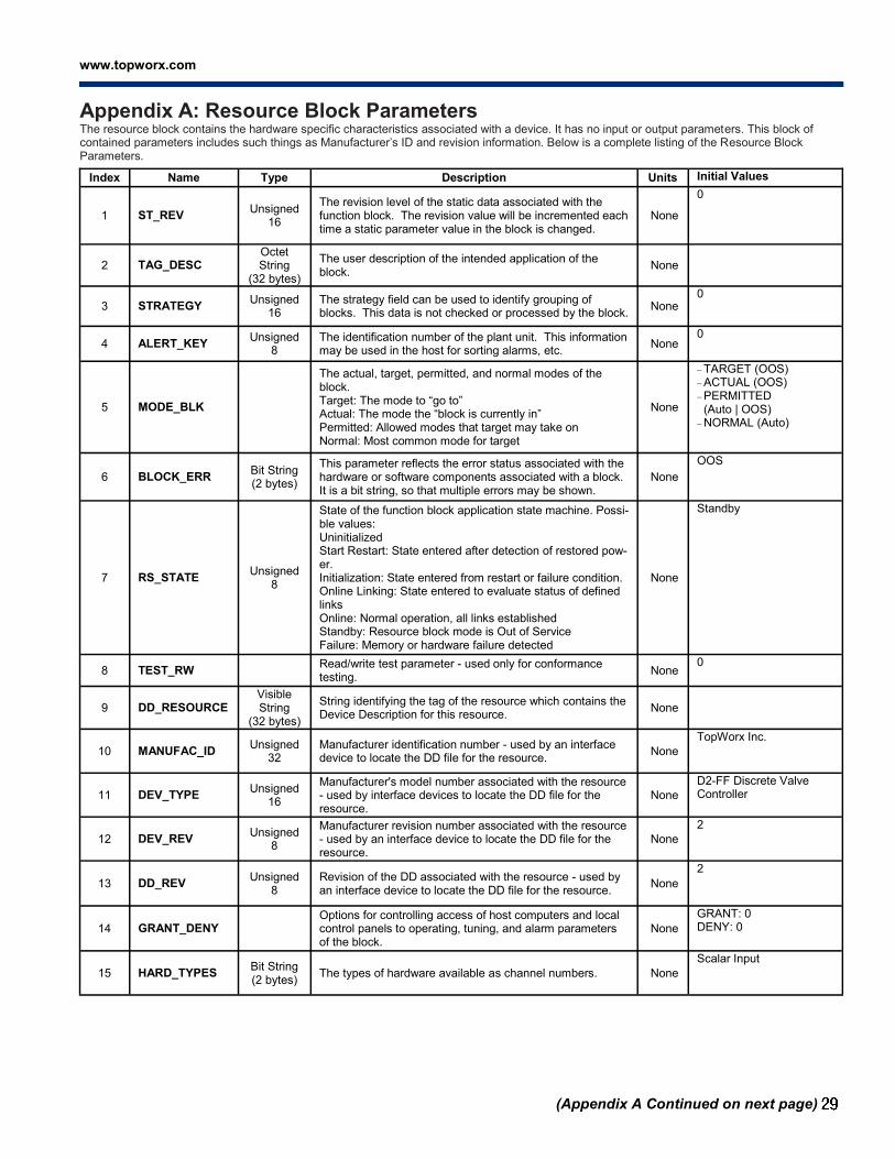
Appendix A: Resource Block Parameters The resource block contains the hardware specific characteristics associated with a device. It has no input or output parameters. This block of contained parameters includes such things as Manufacturer’s ID and revision information. Below is a complete listing of the Resource Block Parameters.
Index Name Type Description Units Initial Values
1 ST_REV Unsigned
16
The revision level of the static data associated with the function block. The revision value will be incremented each time a static parameter value in the block is changed.
None
0
2 TAG_DESC Octet String
(32 bytes)
The user description of the intended application of the block.
None
3 STRATEGY Unsigned
16 The strategy field can be used to identify grouping of blocks. This data is not checked or processed by the block.
None 0
4 ALERT_KEY Unsigned
8 The identification number of the plant unit. This information may be used in the host for sorting alarms, etc.
None 0
5 MODE_BLK
The actual, target, permitted, and normal modes of the block. Target: The mode to “go to” Actual: The mode the “block is currently in” Permitted: Allowed modes that target may take on Normal: Most common mode for target
None
TARGET (OOS) ACTUAL (OOS) PERMITTED
(Auto | OOS) NORMAL (Auto)
6 BLOCK_ERR Bit String (2 bytes)
This parameter reflects the error status associated with the hardware or software components associated with a block. It is a bit string, so that multiple errors may be shown.
None
OOS
7 RS_STATE Unsigned
8
State of the function block application state machine. Possi-ble values: Uninitialized Start Restart: State entered after detection of restored pow-er. Initialization: State entered from restart or failure condition. Online Linking: State entered to evaluate status of defined links Online: Normal operation, all links established Standby: Resource block mode is Out of Service Failure: Memory or hardware failure detected
None
Standby
8 TEST_RW Read/write test parameter - used only for conformance testing.
None 0
9 DD_RESOURCE Visible String
(32 bytes)
String identifying the tag of the resource which contains the Device Description for this resource.
None
10 MANUFAC_ID Unsigned
32 Manufacturer identification number - used by an interface device to locate the DD file for the resource.
None
TopWorx Inc.
11 DEV_TYPE Unsigned
16
Manufacturer's model number associated with the resource - used by interface devices to locate the DD file for the resource.
None
D2-FF Discrete Valve Controller
12 DEV_REV Unsigned
8
Manufacturer revision number associated with the resource - used by an interface device to locate the DD file for the resource.
None
2
13 DD_REV Unsigned
8
Revision of the DD associated with the resource - used by an interface device to locate the DD file for the resource.
None
2
14 GRANT_DENY Options for controlling access of host computers and local control panels to operating, tuning, and alarm parameters of the block.
None
GRANT: 0 DENY: 0
15 HARD_TYPES Bit String (2 bytes)
The types of hardware available as channel numbers. None
Scalar Input
(Appendix A Continued on next page)

D2-FF Installation, Operation & Maintenance 502.969.8000
Appendix A: Resource Block Parameters (Cont.)
Index Name Type Description Units Initial Values
16 RESTART Unsigned 8
Allows a manual restart to be initiated. Supported options: 0: Uninitialized 1: Run: Setting for normal operation 2: Restart resource: Restart resource as though power fail had occurred using NVM values 3: Restart with defaults: Restart resource as through power fail had occurred using default values 4: Restart processor: Reset processor and initiate execu-tion as though power fail had occurred 5: Valve Controller Defaults: Restart D2-FF valve controller board as through power fail had occurred using default values 6: Valve Controller Processor: Reset D2-FF valve controller board processor and initiate execution as though power fail had occurred 11: Restore Factory Default Blocks
None Run
17 FEATURES Bit String (2 bytes)
Used to shows supported resource block options. None
Unicode | Reports | Faultstate | Soft W Lock | Hard W Lock | Out Readback | Multi-bit Alarm (Bit-Alarm) Support | Restart/Relink after FB_Action
18 FEATURE_SEL Bit String (2 bytes)
Used to select resource block options. None
Unicode | Reports | Faultstate | Soft W Lock | Out Readback | Multi-bit Alarm (Bit-Alarm) Support
19 CYCLE_TYPE Bit String (2 bytes)
Identifies the block execution methods available for this resource. Supported values: Scheduled: Block execution is scheduled through system management. Block Execution: Block execution is scheduled the comple-tion of another block Manuf Specific: Block execution is determined by the man-ufacturer
None Scheduled | Block Execution
20 CYCLE_SEL Bit String (2 bytes)
Used to select the block execution method for this re-source. Supported values: Scheduled: Block execution is scheduled through system management. Block Execution: Block execution is scheduled the comple-tion of another block Manuf Specific: Block execution is determined by the man-ufacturer
None 0
21 MIN_CYCLE_T Unsigned 32
Time duration of the shortest cycle interval of which the resource is capable.
1/32 ms
1760
22 MEMORY_SIZE Unsigned 16
Available configuration memory in the empty resource. To be checked before attempting a download.
Kbytes
16
23 NV_CYCLE_T Unsigned 32
Interval between writing copies of NV parameters to non-volatile memory. Zero means never.
1/32 ms
960000
24 FREE_SPACE Float Percent of memory available for further configuration. Zero in a preconfigured device.
% 69.4444
25 FREE_TIME Float Percent of the block processing time that is free to process additional blocks.
% 0
(Appendix A Continued on next page)
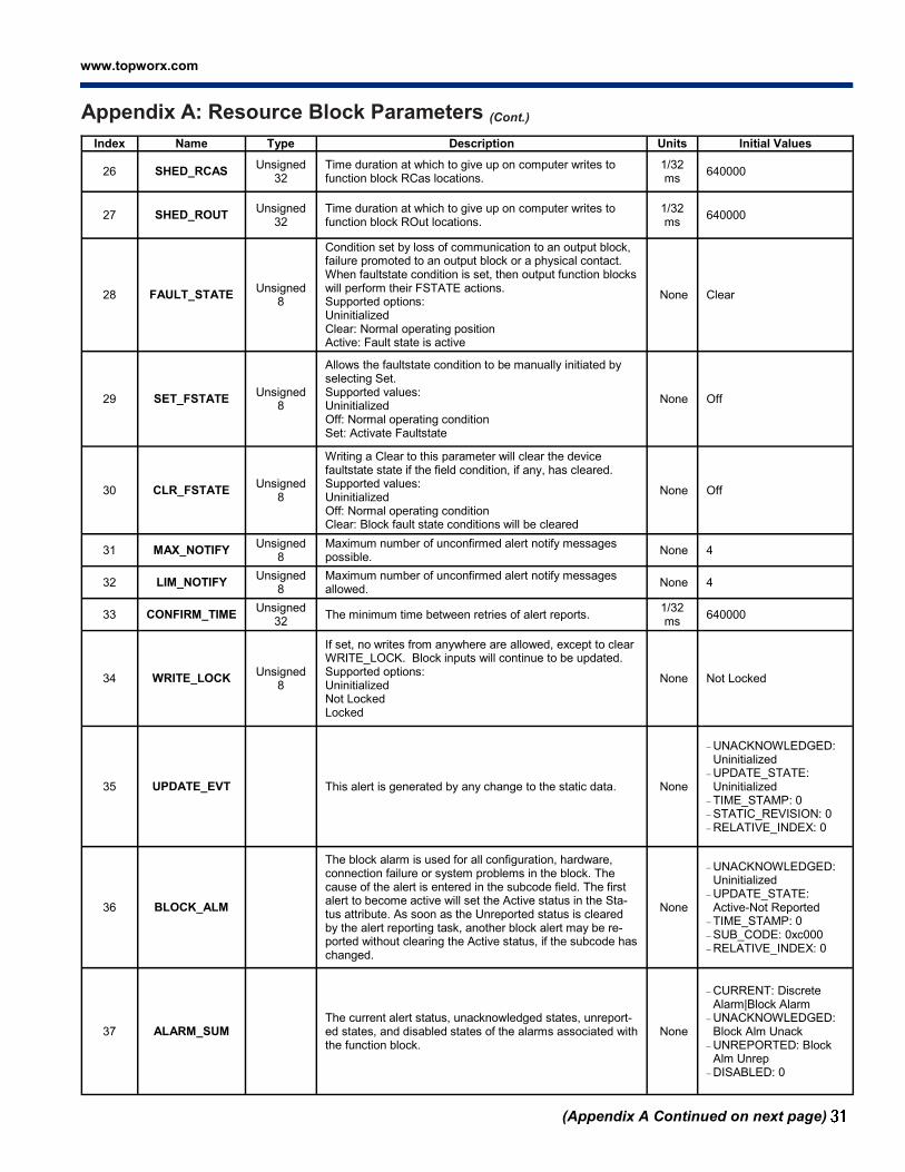
www.topworx.com
®
Index Name Type Description Units Initial Values
26 SHED_RCAS Unsigned
32
Time duration at which to give up on computer writes to function block RCas locations.
1/32 ms
640000
27 SHED_ROUT Unsigned
32
Time duration at which to give up on computer writes to function block ROut locations.
1/32 ms
640000
28 FAULT_STATE Unsigned
8
Condition set by loss of communication to an output block, failure promoted to an output block or a physical contact. When faultstate condition is set, then output function blocks will perform their FSTATE actions. Supported options: Uninitialized Clear: Normal operating position Active: Fault state is active
None Clear
29 SET_FSTATE Unsigned
8
Allows the faultstate condition to be manually initiated by selecting Set. Supported values: Uninitialized Off: Normal operating condition Set: Activate Faultstate
None Off
30 CLR_FSTATE Unsigned
8
Writing a Clear to this parameter will clear the device faultstate state if the field condition, if any, has cleared. Supported values: Uninitialized Off: Normal operating condition Clear: Block fault state conditions will be cleared
None Off
31 MAX_NOTIFY Unsigned
8
Maximum number of unconfirmed alert notify messages possible.
None 4
32 LIM_NOTIFY Unsigned
8
Maximum number of unconfirmed alert notify messages allowed.
None 4
33 CONFIRM_TIME Unsigned
32 The minimum time between retries of alert reports.
1/32 ms
640000
34 WRITE_LOCK Unsigned
8
If set, no writes from anywhere are allowed, except to clear WRITE_LOCK. Block inputs will continue to be updated. Supported options: Uninitialized Not Locked Locked
None Not Locked
35 UPDATE_EVT This alert is generated by any change to the static data. None
UNACKNOWLEDGED: Uninitialized
UPDATE_STATE: Uninitialized
TIME_STAMP: 0 STATIC_REVISION: 0
RELATIVE_INDEX: 0
36 BLOCK_ALM
The block alarm is used for all configuration, hardware, connection failure or system problems in the block. The cause of the alert is entered in the subcode field. The first alert to become active will set the Active status in the Sta-tus attribute. As soon as the Unreported status is cleared by the alert reporting task, another block alert may be re-ported without clearing the Active status, if the subcode has changed.
None
UNACKNOWLEDGED: Uninitialized
UPDATE_STATE: Active-Not Reported
TIME_STAMP: 0
SUB_CODE: 0xc000
RELATIVE_INDEX: 0
37 ALARM_SUM The current alert status, unacknowledged states, unreport-ed states, and disabled states of the alarms associated with the function block.
None
CURRENT: Discrete Alarm|Block Alarm
UNACKNOWLEDGED: Block Alm Unack
UNREPORTED: Block Alm Unrep
DISABLED: 0
(Appendix A Continued on next page)
Appendix A: Resource Block Parameters (Cont.)

D2-FF Installation, Operation & Maintenance 502.969.8000
(Appendix A Continued on next page)
Appendix A: Resource Block Parameters (Cont.)
Index Name Type Description Units Initial Values
38 ACK_OPTION Bit String (2 bytes)
Selection of whether alarms associated with the function block will be automatically acknowl-edged. Supported options: Disc Alm Auto Ack Blk Alm Auto Ack Fail Alm Auto Ack Off Spec Alm Auto Ack Maint Alm Auto Ack Check Alm Auto Ack
None
0
39 WRITE_PRI Unsigned
8
Priority of the alarm generated by clearing the write lock.
None
0
40 WRITE_ALM This alert is generated if the write lock parameter is cleared.
None
UNACKNOWLEDGED: Acknowledged
UPDATE_STATE: Clear-Reported
TIME_STAMP: 0 SUB_CODE: Other VALUE: State 0
41 ITK_VER Unsigned
16
Major revision number of the interoperability test case used to register this device.
None
6
42 FD_VER Unsigned
16
The major version of the Field Diagnostics speci-fication used for the development of this device.
None
1
43 FD_FAIL_ACTIVE Bit String (4 bytes)
This parameter reflects the error conditions that are being detected as active as selected for this category. It is a bit string, so that multiple condi-tions may be shown.
None
0
44 FD_OFFSPEC_ACTIVE Bit String (4 bytes)
This parameter reflects the error conditions that are being detected as active as selected for this category. It is a bit string, so that multiple condi-tions may be shown.
None
0
45 FD_MAINT_ACTIVE Bit String (4 bytes)
This parameter reflects the error conditions that are being detected as active as selected for this category. It is a bit string, so that multiple condi-tions may be shown.
None
0
46 FD_CHECK_ACTIVE Bit String (4 bytes)
This parameter reflects the error conditions that are being detected as active as selected for this category. It is a bit string, so that multiple condi-tions may be shown.
None
0
47 FD_FAIL_MAP Bit String (4 bytes)
This parameter enables or disables conditions to be detected as active for this alarm category. Thus the same condition may be active in all, some, or none of the 3 alarm categories.
None
NV Memory Failure
Electronics Failure
Bad Temperature Sensor Software Error Travel Deviation
Shutdown is Set Buttonboard Failure
Open or Short Circuit Internal I/O Failure
48 FD_OFFSPEC_MAP Bit String (4 bytes)
This parameter enables or disables conditions to be detected as active for this alarm category. Thus the same condition may be active in all, some, or none of the 3 alarm categories.
None
System Temperature Exceeded
Control Module Life Cycle Exceeded
Adjusted Cycle Count Exceeded
Time in Position Limit Exceeded
Open Travel Time Limit Exceeded
Close Travel Time Limit Exceeded
49 FD_MAINT_MAP Bit String (4 bytes)
This parameter enables or disables conditions to be detected as active for this alarm category. Thus the same condition may be active in all, some, or none of the 3 alarm categories.
None
Calibration Failed
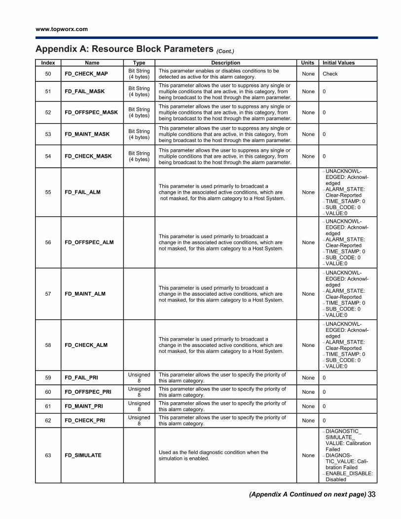
www.topworx.com
®
Index Name Type Description Units Initial Values
50 FD_CHECK_MAP Bit String (4 bytes)
This parameter enables or disables conditions to be detected as active for this alarm category.
None Check
51 FD_FAIL_MASK Bit String (4 bytes)
This parameter allows the user to suppress any single or multiple conditions that are active, in this category, from being broadcast to the host through the alarm parameter.
None 0
52 FD_OFFSPEC_MASK Bit String (4 bytes)
This parameter allows the user to suppress any single or multiple conditions that are active, in this category, from being broadcast to the host through the alarm parameter.
None 0
53 FD_MAINT_MASK Bit String (4 bytes)
This parameter allows the user to suppress any single or multiple conditions that are active, in this category, from being broadcast to the host through the alarm parameter.
None 0
54 FD_CHECK_MASK Bit String (4 bytes)
This parameter allows the user to suppress any single or multiple conditions that are active, in this category, from being broadcast to the host through the alarm parameter.
None 0
55 FD_FAIL_ALM This parameter is used primarily to broadcast a change in the associated active conditions, which are not masked, for this alarm category to a Host System.
None
UNACKNOWL-EDGED: Acknowl-edged
ALARM_STATE: Clear-Reported
TIME_STAMP: 0
SUB_CODE: 0 VALUE:0
56 FD_OFFSPEC_ALM This parameter is used primarily to broadcast a change in the associated active conditions, which are not masked, for this alarm category to a Host System.
None
UNACKNOWL-EDGED: Acknowl-edged
ALARM_STATE: Clear-Reported
TIME_STAMP: 0
SUB_CODE: 0 VALUE:0
57 FD_MAINT_ALM This parameter is used primarily to broadcast a change in the associated active conditions, which are not masked, for this alarm category to a Host System.
None
UNACKNOWL-EDGED: Acknowl-edged
ALARM_STATE: Clear-Reported
TIME_STAMP: 0
SUB_CODE: 0
VALUE:0
58 FD_CHECK_ALM This parameter is used primarily to broadcast a change in the associated active conditions, which are not masked, for this alarm category to a Host System.
None
UNACKNOWL-EDGED: Acknowl-edged
ALARM_STATE: Clear-Reported
TIME_STAMP: 0 SUB_CODE: 0
VALUE:0
59 FD_FAIL_PRI Unsigned
8
This parameter allows the user to specify the priority of this alarm category.
None 0
60 FD_OFFSPEC_PRI Unsigned
8
This parameter allows the user to specify the priority of this alarm category.
None 0
61 FD_MAINT_PRI Unsigned
8
This parameter allows the user to specify the priority of this alarm category.
None 0
62 FD_CHECK_PRI Unsigned
8
This parameter allows the user to specify the priority of this alarm category.
None 0
63 FD_SIMULATE Used as the field diagnostic condition when the simulation is enabled.
None
DIAGNOSTIC_ SIMULATE_ VALUE: Calibration Failed
DIAGNOS-TIC_VALUE: Cali-bration Failed
ENABLE_DISABLE: Disabled
(Appendix A Continued on next page)
Appendix A: Resource Block Parameters (Cont.)
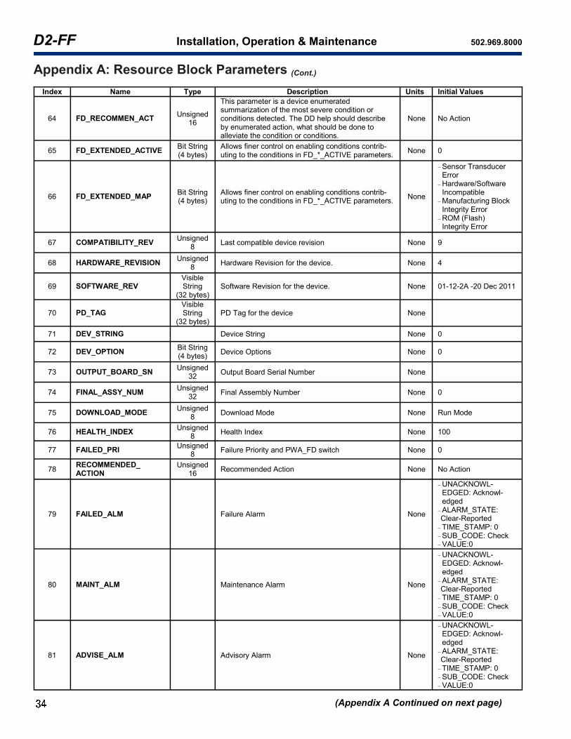
D2-FF Installation, Operation & Maintenance 502.969.8000
(Appendix A Continued on next page)
Appendix A: Resource Block Parameters (Cont.)
Index Name Type Description Units Initial Values
64 FD_RECOMMEN_ACT Unsigned
16
This parameter is a device enumerated summarization of the most severe condition or conditions detected. The DD help should describe by enumerated action, what should be done to alleviate the condition or conditions.
None No Action
65 FD_EXTENDED_ACTIVE Bit String (4 bytes)
Allows finer control on enabling conditions contrib-uting to the conditions in FD_*_ACTIVE parameters.
None 0
66 FD_EXTENDED_MAP Bit String (4 bytes)
Allows finer control on enabling conditions contrib-uting to the conditions in FD_*_ACTIVE parameters.
None
Sensor Transducer Error
Hardware/Software Incompatible
Manufacturing Block Integrity Error
ROM (Flash) Integrity Error
67 COMPATIBILITY_REV Unsigned
8 Last compatible device revision None 9
68 HARDWARE_REVISION Unsigned
8 Hardware Revision for the device. None 4
69 SOFTWARE_REV Visible String
(32 bytes) Software Revision for the device. None 01-12-2A -20 Dec 2011
70 PD_TAG Visible String
(32 bytes) PD Tag for the device None
71 DEV_STRING Device String None 0
72 DEV_OPTION Bit String (4 bytes)
Device Options None 0
73 OUTPUT_BOARD_SN Unsigned
32 Output Board Serial Number None
74 FINAL_ASSY_NUM Unsigned
32 Final Assembly Number None 0
75 DOWNLOAD_MODE Unsigned
8 Download Mode None Run Mode
76 HEALTH_INDEX Unsigned
8 Health Index None 100
77 FAILED_PRI Unsigned
8 Failure Priority and PWA_FD switch None 0
78 RECOMMENDED_ ACTION
Unsigned 16
Recommended Action None No Action
79 FAILED_ALM Failure Alarm None
UNACKNOWL-EDGED: Acknowl-edged
ALARM_STATE: Clear-Reported
TIME_STAMP: 0
SUB_CODE: Check VALUE:0
80 MAINT_ALM Maintenance Alarm None
UNACKNOWL-EDGED: Acknowl-edged
ALARM_STATE: Clear-Reported
TIME_STAMP: 0
SUB_CODE: Check VALUE:0
81 ADVISE_ALM Advisory Alarm None
UNACKNOWL-EDGED: Acknowl-edged
ALARM_STATE: Clear-Reported
TIME_STAMP: 0
SUB_CODE: Check VALUE:0

www.topworx.com
®
Index Name Type Description Units Initial Values
82 FAILED_ENABLE Bit String (4 bytes)
Failure Enable None
NV Memory Failure
Electronics Failure Bad Temperature Sensor Software Error Travel Deviation Shutdown is Set Buttonboard Failure
Open or Short Circuit Internal I/O Failure
83 FAILED_MASK Bit String (4 bytes)
Failure Mask None 0
84 FAILED_ACTIVE Bit String (4 bytes)
Failure Active None 0
85 MAINT_PRI Unsigned
8 Maintenance Priority None 0
86 MAINT_ENABLE Bit String (4 bytes)
Maintenance Enable None
System Temperature Exceeded
Control Module Life Cycle Exceeded
Adjusted Cycle Count Exceeded
Time in Position Limit Exceeded
Open Travel Time Limit Exceeded
Close Travel Time Limit Exceeded
87 MAINT_MASK Bit String (4 bytes)
Maintenance Mask None 0
88 MAINT_ACTIVE Bit String (4 bytes)
Maintenance Active None 0
89 ADVISE_PRI Unsigned
8 Advisory Priority None 0
90 ADVISE_ENABLE Bit String (4 bytes)
Advisory Enable None Check | Calibration Failed
91 ADVISE_MASK Bit String (4 bytes)
Advisory Mask None 0
92 ADVISE_ACTIVE Bit String (4 bytes)
Advisory Active None 0
93 DISTRIBUTOR Unsigned
32 Private Label Distributor None 0x00545758 (TopWorx Inc.)
94 ELECTRONICS_ SN
Unsigned 8
The Manufacturer Specific Serial Number for the Electronics assembly within the instrument.
None 1
95 FACTORY_SN Visible
String (9 bytes)
The Serial number of the Instrument as assigned at the Factory. This parameter can only be changed by the Factory.
None
96 FIELD_SN
Visible String (32
bytes)
This is the Instrument Serial Number, as assigned by the user, as applied to his field application.
None
97 DIAG_OPTIONS Bit String (4 bytes)
Diagnostic Options None 0
98 CONTROL_ CARD_SW_REV
Float Control card software revision number None 1.3 (1.4 for applications with-out integral piezo pilots)
(Appendix A Continued on next page)
Appendix A: Resource Block Parameters (Cont.)
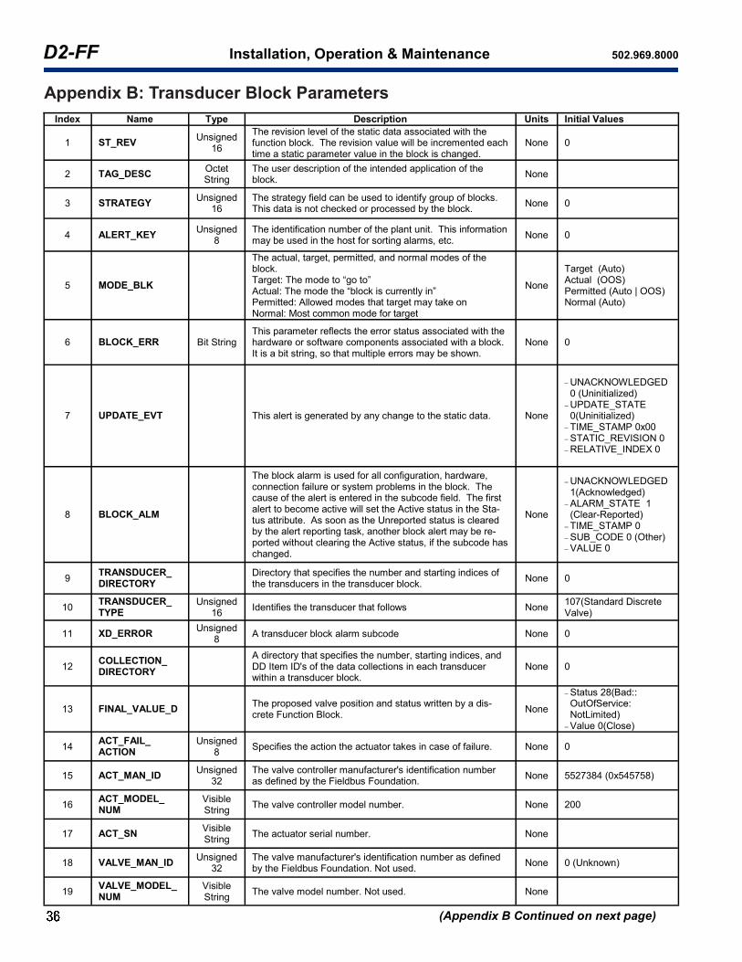
D2-FF Installation, Operation & Maintenance 502.969.8000
(Appendix B Continued on next page)
Appendix B: Transducer Block Parameters
Index Name Type Description Units Initial Values
1 ST_REV Unsigned
16
The revision level of the static data associated with the function block. The revision value will be incremented each time a static parameter value in the block is changed.
None 0
2 TAG_DESC Octet String
The user description of the intended application of the block.
None
3 STRATEGY Unsigned
16 The strategy field can be used to identify group of blocks. This data is not checked or processed by the block.
None 0
4 ALERT_KEY Unsigned
8
The identification number of the plant unit. This information may be used in the host for sorting alarms, etc.
None 0
5 MODE_BLK
The actual, target, permitted, and normal modes of the block. Target: The mode to “go to” Actual: The mode the “block is currently in” Permitted: Allowed modes that target may take on Normal: Most common mode for target
None
Target (Auto) Actual (OOS) Permitted (Auto | OOS) Normal (Auto)
6 BLOCK_ERR Bit String This parameter reflects the error status associated with the hardware or software components associated with a block. It is a bit string, so that multiple errors may be shown.
None 0
7 UPDATE_EVT This alert is generated by any change to the static data. None
UNACKNOWLEDGED 0 (Uninitialized)
UPDATE_STATE 0(Uninitialized)
TIME_STAMP 0x00
STATIC_REVISION 0 RELATIVE_INDEX 0
8 BLOCK_ALM
The block alarm is used for all configuration, hardware, connection failure or system problems in the block. The cause of the alert is entered in the subcode field. The first alert to become active will set the Active status in the Sta-tus attribute. As soon as the Unreported status is cleared by the alert reporting task, another block alert may be re-ported without clearing the Active status, if the subcode has changed.
None
UNACKNOWLEDGED 1(Acknowledged)
ALARM_STATE 1(Clear-Reported)
TIME_STAMP 0
SUB_CODE 0 (Other) VALUE 0
9 TRANSDUCER_ DIRECTORY
Directory that specifies the number and starting indices of the transducers in the transducer block.
None 0
10 TRANSDUCER_ TYPE
Unsigned 16
Identifies the transducer that follows None 107(Standard Discrete Valve)
11 XD_ERROR Unsigned
8 A transducer block alarm subcode None 0
12 COLLECTION_ DIRECTORY
A directory that specifies the number, starting indices, and DD Item ID's of the data collections in each transducer within a transducer block.
None 0
13 FINAL_VALUE_D The proposed valve position and status written by a dis-crete Function Block.
None
Status 28(Bad:: OutOfService: NotLimited)
Value 0(Close)
14 ACT_FAIL_ ACTION
Unsigned 8
Specifies the action the actuator takes in case of failure. None 0
15 ACT_MAN_ID Unsigned
32
The valve controller manufacturer's identification number as defined by the Fieldbus Foundation.
None 5527384 (0x545758)
16 ACT_MODEL_ NUM
Visible String
The valve controller model number. None 200
17 ACT_SN Visible String
The actuator serial number. None
18 VALVE_MAN_ID Unsigned
32
The valve manufacturer's identification number as defined by the Fieldbus Foundation. Not used.
None 0 (Unknown)
19 VALVE_MODEL_NUM
Visible String
The valve model number. Not used. None
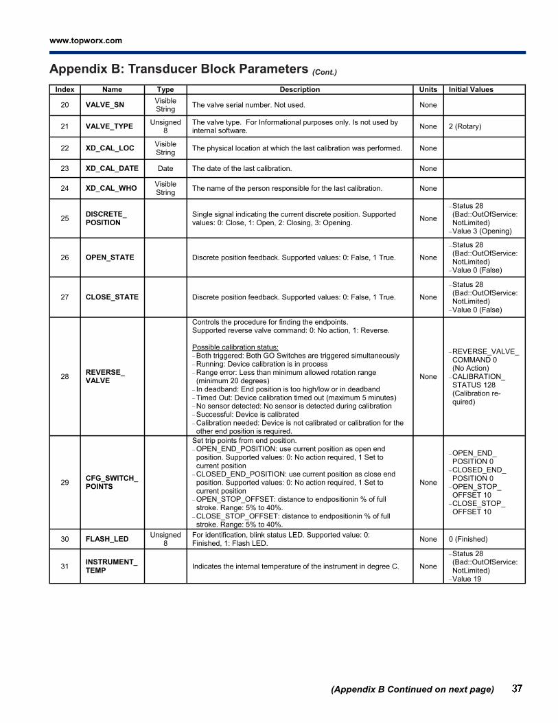
www.topworx.com
®
Index Name Type Description Units Initial Values
20 VALVE_SN Visible String
The valve serial number. Not used. None
21 VALVE_TYPE Unsigned
8 The valve type. For Informational purposes only. Is not used by internal software.
None 2 (Rotary)
22 XD_CAL_LOC Visible String
The physical location at which the last calibration was performed. None
23 XD_CAL_DATE Date The date of the last calibration. None
24 XD_CAL_WHO Visible String
The name of the person responsible for the last calibration. None
25 DISCRETE_ POSITION
Single signal indicating the current discrete position. Supported values: 0: Close, 1: Open, 2: Closing, 3: Opening.
None
Status 28 (Bad::OutOfService: NotLimited)
Value 3 (Opening)
26 OPEN_STATE Discrete position feedback. Supported values: 0: False, 1 True. None
Status 28(Bad::OutOfService:NotLimited)
Value 0 (False)
27 CLOSE_STATE Discrete position feedback. Supported values: 0: False, 1 True. None
Status 28(Bad::OutOfService:NotLimited)
Value 0 (False)
28 REVERSE_ VALVE
Controls the procedure for finding the endpoints. Supported reverse valve command: 0: No action, 1: Reverse. Possible calibration status: Both triggered: Both GO Switches are triggered simultaneously
Running: Device calibration is in process
Range error: Less than minimum allowed rotation range (minimum 20 degrees)
In deadband: End position is too high/low or in deadband
Timed Out: Device calibration timed out (maximum 5 minutes) No sensor detected: No sensor is detected during calibration
Successful: Device is calibrated Calibration needed: Device is not calibrated or calibration for the other end position is required.
None
REVERSE_VALVE_ COMMAND 0 (No Action)
CALIBRATION_ STATUS 128 (Calibration re-quired)
29 CFG_SWITCH_ POINTS
Set trip points from end position. OPEN_END_POSITION: use current position as open end position. Supported values: 0: No action required, 1 Set to current position
CLOSED_END_POSITION: use current position as close end position. Supported values: 0: No action required, 1 Set to current position
OPEN_STOP_OFFSET: distance to endpositionin % of full stroke. Range: 5% to 40%.
CLOSE_STOP_OFFSET: distance to endpositionin % of full stroke. Range: 5% to 40%.
None
OPEN_END_ POSITION 0
CLOSED_END_ POSITION 0
OPEN_STOP_ OFFSET 10
CLOSE_STOP_ OFFSET 10
30 FLASH_LED Unsigned
8
For identification, blink status LED. Supported value: 0: Finished, 1: Flash LED.
None 0 (Finished)
31 INSTRUMENT_ TEMP
Indicates the internal temperature of the instrument in degree C. None
Status 28(Bad::OutOfService:NotLimited)
Value 19
(Appendix B Continued on next page)
Appendix B: Transducer Block Parameters (Cont.)

D2-FF Installation, Operation & Maintenance 502.969.8000
(Appendix B Continued on next page)
Appendix B: Transducer Block Parameters
Index Name Type Description Units Initial Values
32 SHUTDOWN_CFG
Configures what actions to take after internal communications are lost. SHUTDOWN_ENABLE: Shutdown Enable. Supported values:
0: Enable auto recovery, 1: Enable manual recovery, 2: Disable
SHUTDOWN_ACTION: Action that the valve will take if there is a Shutdown. Supported values: 0: Close, 1: Open, 2: Hold
SHUTDOWN_DELAY_TIME: Time in seconds before action will be taken after an event has occurred.
SHUTDOWN_RESET: If shutdown status indicates shutdown enable was set to manual recovery, then operator must set this parameter to normal operation before the device can recover. Supported values: 0: Inactive, 1: Reset.
SHUTDOWN_STATUS: Indicates if the system is shutdown or operational. Supported values: 0: Device operational, 1: Device shutdown.
None
SHUTDOWN_ ENABLE 1 (Enable manual recovery)
SHUTDOWN_ ACTION 0(Close) SHUTDOWN_ DELAY_TIME 5 SHUTDOWN_
RESET 0(Inactive) SHUTDOWN_ STATUS 0 (Device operational)
33 SENSOR_TYPE_ TOPWORX
Unsigned 8
The sensor type that determines the position. Supported values:0: Not assigned, 1: GO switches only, 2: Potentiometer only, 3: Both potentiometer and GO Switches.
None 0 (Not assigned)
34 BUTTONBOARD_ ENABLE
Unsigned 8
Enables and disables the buttonboard for initialization and reas-signment of end positions. Can only be enabled when device is in OOS. Supported values: 0: Never active, 1: Active in OOS.
None 1 (Active in OOS)
35 INTERNAL_ ALERTS
Bit String
Internal Alerts. Available items: Open/short circuit error, Calibration Failure, Bad temperature sensor, System temperature exceeded, Software error IO card, Travel deviation alert, Device shutdown, Buttonboard failure
None 0x4000 (Calibration Failure)
36 FUNCTION_ MODULE_ COUNTER
Counts the end position cycles performed by the control module. FM_COUNTER_VALUE: Control module cycle count value. FM_COUNTER_LIMIT: Control module cycle count limit.
None
FM_COUNTER_ VALUE 5
FM_COUNTER_ LIMIT 1000000
37 PNEUMATIC_ MODULE_ COUNTER
Counts the end position cycles performed by the control module. ADJUSTED_COUNT_VALUE: Adjusted control module cycle count value. ADJUSTED_COUNT_LIMIT: Adjusted control module cycle count limit.
None
ADJUSTED_ COUNT_VALUE 5
ADJUSTED_ COUNT_LIMIT 1000000
38 VALVE_POSITION Unsigned
32 Indicates valve position in percentage % 0
39 TIMERS
Diagnostic timers in seconds for device
TIME_IN_POSTION: Holds the time in current position but not saved in NV, so reset when power is switched off.
TIME_IN_POSITION_HI_LIM: Sets a limit for an alert for the time in position.
OPEN_TRAVEL_TIME: Indicates time between position change commanded and open trip position reached.
OPEN_TRAVEL_TIME_HI_LIM: Open travel time high limit. OPEN_TRAVEL_TIME_LO_LIM: Open travel time low limit. OPEN_TRAVEL_TIME_AVERAGE: Open travel time average. OPEN_TRAVEL_AVERAGE_HI_LIM: Open travel time average high limit.
OPEN_TRAVEL_AVERAGE_LO_LIM: Open travel time average low limit.
CLOSE_TRAVEL_TIME: Indicates time between position change commanded and close trip position reached.
CLOSE_TRAVEL_TIME_HI_LIM: Close travel time high limit. CLOSE_TRAVEL_TIME_LO_LIM: Close travel time low limit. CLOSE_TRAVEL_TIME_AVERAGE: Close travel time average. CLOSE_TRAVEL_AVERAGE_HI_LIM: Close travel time average high limit.
CLOSE_TRAVEL_AVERAGE_LO_LIM: Close travel time aver-age low limit.
None
TIME_IN_POSTION 0 TIME_IN_POSITION_
HI_LIM 864000 OPEN_TRAVEL_
TIME 0 OPEN_TRAVEL_
TIME_HI_LIM 300 OPEN_TRAVEL_
TIME_LO_LIM 0 OPEN_TRAVEL_
TIME_AVERAGE 0 OPEN_TRAVEL_
AVERAGE_HI_LIM 300 OPEN_TRAVEL_
AVERAGE_LO_LIM 0 CLOSE_TRAVEL_
TIME 0 CLOSE_TRAVEL_
TIME_HI_LIM 300 CLOSE_TRAVEL_
TIME_LO_LIM 0 CLOSE_TRAVEL_
TIME_AVERAGE 0 CLOSE_TRAVEL_
AVERAGE_HI_LIM 300 CLOSE_TRAVEL_
AVERAGE_LO_LIM 0

www.topworx.com
®
Index Name Type Description Units Initial Values
40 FF_COMM_ STATS
Statistics which indicate interboard communication quality. FF_COMM_ATTEMPTS: States the number of interboard communication attempts. Counter will be reset to 0 when max count is reached.
FF_COMM_TIMOUTS: Counts the communication attempts that timed out.
None
FF_COMM_ ATTEMPTS 0
FF_COMM_ TIMEOUTS 0
41 BASE_RECORD
Base Record for Low Level Device Access. BASE_VALUE: Value to be sent or received from valve controller.
BASE_COMMAND: Command controlling base array. Supported commands are listed as following: No Command/Exit Method Get Current Real Position
Get Open Endpoint Get Close Endpoint Get Min Temp Ever Get Max Temp Ever
None BASE_VALUE 0 BASE_ COMMAND 0
(Appendix C Continued)
Appendix B: Transducer Block Parameters (Concluded)
Index Name Type Description Units Initial Values
1 ST_REV Unsigned
16
The revision level of the static data associated with the function block. The revision value will be incremented each time a static parameter value in the block is changed.
None 0
2 TAG_DESC Octet String
The user description of the intended application of the block.
None
3 STRATEGY Unsigned
16
The strategy field can be used to identify grouping of blocks. This data is not checked or processed by the block.
None 0
4 ALERT_KEY Unsigned
8
The identification number of the plant unit. This information may be used in the host for sorting alarms, etc.
None 0
5 MODE_BLK
The actual, target, permitted, and normal modes of the block. Target: The mode to “go to” Actual: The mode the “block is currently in” Permitted: Allowed modes that target may take on Normal: Most common mode for target
None
TARGET (OOS) ACTUAL (OOS) PERMITTED (Auto | Man | OOS)
NORMAL (Auto)
6 BLOCK_ERR Bit String
This parameter reflects the error status associated with the hardware or software components associated with a block. It is a bit string, so that multiple errors may be shown.
None 0
7 PV Either the primary analog value for use in executing the function, or a process value associated with it. May also be calculated from the READBACK value of an AO block
EU of XD_ SCALE
STATUS 0 VALUE 0
8 OUT The primary analog value calculated as a result of execut-ing the function block
EU of OUT_ SCALE
STATUS 0 VALUE 0
Appendix C: AI Function Block Parameters

D2-FF Installation, Operation & Maintenance 502.969.8000
(Appendix C Concluded on next page)
Appendix C: AI Function Block Parameters (Cont.)
Index Name Type Description Units Initial Values
9 SIMULATE
Allows the transducer analog input or output to the block to be manually supplied when simulate is enabled. When simulate is disabled, the simulate value and status track the actual value and status.
None
SIMULATE_STATUS 0
SIMULATE_VALUE 0
TRANSDUCER_ STATUS 0 Bad::NonSpecific: NotLimited)
TRANSDUCER_ VALUE 0
ENABLE_DISABLE 1(Disabled)
10 XD_SCALE The high and low scale values, engineering units code, and number of digits to the right of the decimal point used with the value obtained from the transducer for a specified channel.
None
EU_100 100
EU_0 0
UNITS_INDEX 1342(%)
DECIMAL 2
11 OUT_SCALE The high and low scale values, engineering units code, and number of digits to the right of the decimal point to be used in displaying the OUT parameter and parameters which have the same scaling as OUT
None
EU_100 100
EU_0 0
UNITS_INDEX 1342(%)
DECIMAL 0
12 GRANT_DENY Options for controlling access of host computers and local control panels to operating, tuning, and alarm parameters of the block.
None GRANT 0
DENY 0
13 IO_OPTS Bit String Option which the user may select to alter input and output block processing.
None 0
14 STATUS_OPTS Bit String Options which the user may select in the block processing of status. None 0
15 CHANNEL Unsigned
16
The number of the logical hardware channel that is connected to this I/O block. This information defines the transducer to be used going to or from the physical world. Supported channels are listed on the following: 0: No Channel Selected 5: Instrument Temperature 6: Analog Position
None 0 (No channel selected)
16 L_TYPE Unsigned
8
Determines if the values passed by the transducer block to the
AI block may be used directly (Direct) or if the value is in different units and must be converted linearly (Indirect), or with square root (Ind Sqr Root), using the input range defined for the transducer and the associated output range.
None 1 (Direct)
17 LOW_CUT Float
Limit used in square root processing. A value of zero percent of scale is used in block processing if the transducer value falls below this limit, in % of scale. This feature may be used to eliminate noise near zero from a flow sensor.
% 0
18 PV_FTIME Float Time constant of a single exponential filter for the PV, in seconds. Seconds 0
19 FIELD_VAL Raw value of the field device in % of PV range, with a status reflecting the Transducer condition, before signal characterization (L_TYPE) or filtering (PV_FTIME).
% STATUS 0
VALUE 0
20 UPDATE_EVT This alert is generated by any change to the static data. None
UNACKNOWLEDGED 0 (Uninitialized)
UPDATE_STATE 0
TIME_STAMP 0
STATIC_REVISION 0
RELATIVE_INDEX 0
21 BLOCK_ALM
The block alarm is used for all configuration, hardware, connection failure or system problems in the block. The cause of the alert is entered in the subcode field. The first alert to become active will set the Active status in the Status attribute. As soon as the Unreported status is cleared by the alert reporting task, another block alert may be reported without clearing the Active status, if the subcode has changed.
None
UNACKNOWLEDGED 0(Uninitialized)
ALARM_STATE 0
TIME_STAMP 0
SUB_CODE 0
VALUE 0
22 ALARM_SUM The current alert status, unacknowledged states, unreported states, and disabled states of the alarms associated with the function block.
None
CURRENT 0
UNACKNOWLEDGED 0
UNREPORTED 0
DISABLED 0

www.topworx.com
®
(Appendix C Concluded)
Appendix C: AI Function Block Parameters (Concluded)
Index Name Type Description Units Initial Values
23 ACK_OPTION Bit String Selection of whether alarms associated with the function block will be automatically acknowl-edged.
None 0
24 ALARM_HYS Float Amount the PV must return within the alarm limits before the alarm condition clears. Alarm hystere-sis expressed as a percent of the span of the PV.
% 0.5
25 HI_HI_PRI Unsigned
8 Priority of the high high alarm. None 0
26 HI_HI_LIM Float The setting for high high alarm in engineering units.
EU of PV_SCALE Positive Infinity
27 HI_PRI Unsigned
8 Priority of the high alarm None 0
28 HI_LIM Float The setting for high alarm in engineering units EU of PV_SCALE Positive Infinity
29 LO_PRI Unsigned
8 Priority of the low alarm None 0
30 LO_LIM Float The setting for the low alarm in engineering units. EU of PV_SCALE Negative Infinity
31 LO_LO_PRI Unsigned
8 Priority of the low low alarm. None 0
32 LO_LO_LIM Float The setting of the low low alarm in engineering units
EU of PV_SCALE Negative Infinity
33 HI_HI_ALM The status for high high alarm and its associated time stamp
None
UNACKNOWLEDGED 0(Uninitialized)
ALARM_STATE 0
TIME_STAMP 0
SUB_CODE 0
VALUE 0
34 HI_ALM The status for high alarm and its associated time stamp.
None
UNACKNOWLEDGED 0(Uninitialized)
ALARM_STATE 0
TIME_STAMP 0
SUB_CODE 0
VALUE 0
35 LO_ALM The status of the low alarm and its associated time stamp.
None
UNACKNOWLEDGED (Uninitialized)
ALARM_STATE 0
TIME_STAMP 0
SUB_CODE 0
VALUE 0
36 LO_LO_ALM The status of the low low alarm and its associated time stamp.
None
UNACKNOWLEDGED 0(Uninitialized)
ALARM_STATE 0
TIME_STAMP 0
SUB_CODE 0
VALUE 0
37 OUT_D The primary discrete value calculated as a result of executing the function block.
None STATUS 0
(Bad::NonSpecific:NotLimited) VALUE 0
38 ALM_SEL Bit String Selected alarms that activate the alarm output None 0
39 STDDEV Float Standard deviation of the measurement. % 0
40 CAP_STDDEV
Float Capability standard deviation, the best deviation that can be achieved.
Seconds 0

D2-FF Installation, Operation & Maintenance 502.969.8000
(Appendix C Concluded on next page)
Appendix C: AI Function Block Parameters (Cont.)
Index Name Type Description Units Initial Values
9 SIMULATE
Allows the transducer analog input or output to the block to be manually supplied when simulate is enabled. When simulate is disabled, the simulate value and status track the actual value and status.
None
SIMULATE_STATUS 0
SIMULATE_VALUE 0
TRANSDUCER_ STATUS 0 Bad::NonSpecific: NotLimited)
TRANSDUCER_ VALUE 0
ENABLE_DISABLE 1 (Disabled)
10 XD_SCALE The high and low scale values, engineering units code, and num-ber of digits to the right of the decimal point used with the value obtained from the transducer for a specified channel.
None
EU_100 100
EU_0 0
UNITS_INDEX 1342(%) DECIMAL 2
11 OUT_SCALE
The high and low scale values, engineering units code, and num-ber of digits to the right of the decimal point to be used in display-ing the OUT parameter and parameters which have the same scaling as OUT
None
EU_100 100
EU_0 0
UNITS_INDEX 1342(%) DECIMAL 0
12 GRANT_DENY Options for controlling access of host computers and local control panels to operating, tuning, and alarm parameters of the block.
None GRANT 0
DENY 0
13 IO_OPTS Bit String Option which the user may select to alter input and output block processing.
None 0
14 STATUS_OPTS Bit String Options which the user may select in the block processing of status.
None 0
15 CHANNEL Unsigned
16
The number of the logical hardware channel that is connected to this I/O block. This information defines the transducer to be used going to or from the physical world. Supported channels are listed on the following: 0: No Channel Selected 5: Instrument Temperature 6: Analog Position
None 0 (No channel selected)
16 L_TYPE Unsigned
8
Determines if the values passed by the transducer block to the AI
block may be used directly (Direct) or if the value is in different units and must be converted linearly (Indirect), or with square root (Ind Sqr Root), using the input range defined for the transducer and the associated output range.
None 1 (Direct)
17 LOW_CUT Float
Limit used in square root processing. A value of zero percent of scale is used in block processing if the transducer value falls below this limit, in % of scale. This feature may be used to elimi-nate noise near zero from a flow sensor.
% 0
18 PV_FTIME Float Time constant of a single exponential filter for the PV, in seconds. Seconds 0
19 FIELD_VAL Raw value of the field device in % of PV range, with a status reflecting the Transducer condition, before signal characterization (L_TYPE) or filtering (PV_FTIME).
% STATUS 0
VALUE 0
20 UPDATE_EVT This alert is generated by any change to the static data. None
UNACKNOWLEDGED 0 (Uninitialized)
UPDATE_STATE 0
TIME_STAMP 0
STATIC_REVISION 0
RELATIVE_INDEX 0
21 BLOCK_ALM
The block alarm is used for all configuration, hardware, connec-tion failure or system problems in the block. The cause of the alert is entered in the subcode field. The first alert to become active will set the Active status in the Status attribute. As soon as the Unreported status is cleared by the alert reporting task, anoth-er block alert may be reported without clearing the Active status, if the subcode has changed.
None
UNACKNOWLEDGED 0 (Uninitialized)
ALARM_STATE 0
TIME_STAMP 0
SUB_CODE 0
VALUE 0
22 ALARM_SUM The current alert status, unacknowledged states, unreported states, and disabled states of the alarms associated with the function block.
None
CURRENT 0
UNACKNOWLEDGED 0
UNREPORTED 0
DISABLED 0
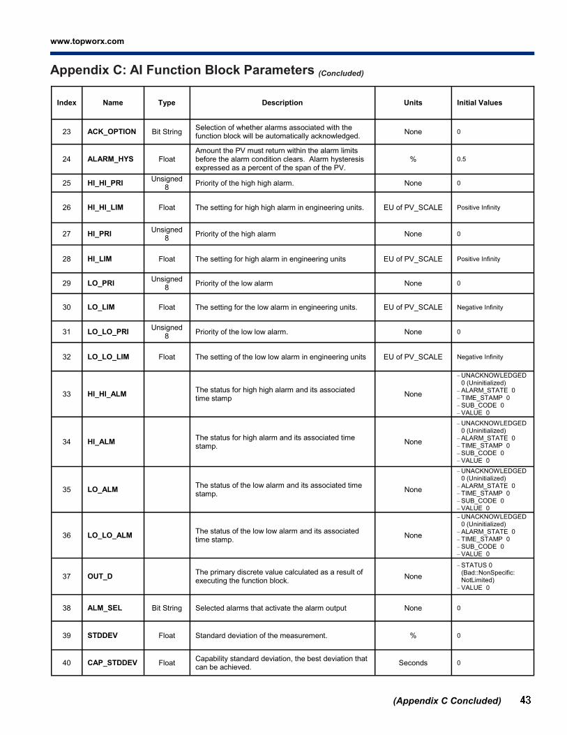
www.topworx.com
®
(Appendix C Concluded)
Appendix C: AI Function Block Parameters (Concluded)
Index Name Type Description Units Initial Values
23 ACK_OPTION Bit String Selection of whether alarms associated with the function block will be automatically acknowledged.
None 0
24 ALARM_HYS Float Amount the PV must return within the alarm limits before the alarm condition clears. Alarm hysteresis expressed as a percent of the span of the PV.
% 0.5
25 HI_HI_PRI Unsigned
8 Priority of the high high alarm. None 0
26 HI_HI_LIM Float The setting for high high alarm in engineering units. EU of PV_SCALE Positive Infinity
27 HI_PRI Unsigned
8 Priority of the high alarm None 0
28 HI_LIM Float The setting for high alarm in engineering units EU of PV_SCALE Positive Infinity
29 LO_PRI Unsigned
8 Priority of the low alarm None 0
30 LO_LIM Float The setting for the low alarm in engineering units. EU of PV_SCALE Negative Infinity
31 LO_LO_PRI Unsigned
8 Priority of the low low alarm. None 0
32 LO_LO_LIM Float The setting of the low low alarm in engineering units EU of PV_SCALE Negative Infinity
33 HI_HI_ALM The status for high high alarm and its associated time stamp
None
UNACKNOWLEDGED 0 (Uninitialized)
ALARM_STATE 0
TIME_STAMP 0
SUB_CODE 0
VALUE 0
34 HI_ALM The status for high alarm and its associated time stamp.
None
UNACKNOWLEDGED 0 (Uninitialized)
ALARM_STATE 0
TIME_STAMP 0
SUB_CODE 0
VALUE 0
35 LO_ALM The status of the low alarm and its associated time stamp.
None
UNACKNOWLEDGED 0 (Uninitialized)
ALARM_STATE 0
TIME_STAMP 0
SUB_CODE 0
VALUE 0
36 LO_LO_ALM The status of the low low alarm and its associated time stamp.
None
UNACKNOWLEDGED 0 (Uninitialized)
ALARM_STATE 0
TIME_STAMP 0
SUB_CODE 0
VALUE 0
37 OUT_D The primary discrete value calculated as a result of executing the function block.
None
STATUS 0(Bad::NonSpecific: NotLimited)
VALUE 0
38 ALM_SEL Bit String Selected alarms that activate the alarm output None 0
39 STDDEV Float Standard deviation of the measurement. % 0
40 CAP_STDDEV Float Capability standard deviation, the best deviation that can be achieved.
Seconds 0

D2-FF Installation, Operation & Maintenance 502.969.8000
(Appendix D Contcluded on next page)
Appendix D: DI Function Block Parameters
Index Name Type Description Units Initial Values
1 ST_REV Unsigned
16
The revision level of the static data associated with the function block. The revision value will be incremented each time a static parameter value in the block is changed.
None 0
2 TAG_DESC Octet String
The user description of the intended application of the block.
None
3 STRATEGY Unsigned
16 The strategy field can be used to identify grouping of blocks. This data is not checked or processed by the block.
None 0
4 ALERT_KEY Unsigned
8
The identification number of the plant unit. This information may be used in the host for sorting alarms, etc.
None 0
5 MODE_BLK
The actual, target, permitted, and normal modes of the block. Target: The mode to “go to” Actual: The mode the “block is currently in” Permitted: Allowed modes that target may take on Normal: Most common mode for target
None
TARGET (OOS) ACTUAL (OOS) PERMITTED
(Auto | Man | OOS) NORMAL (Auto)
6 BLOCK_ERR Bit String This parameter reflects the error status associated with the hardware or software components associated with a block. It is a bit string, so that multiple errors may be shown.
None 0
7 PV_D Either the primary discrete value for use in executing the function, or a process value associated with it. May also be calculated from the READBACK_D value of a DO block.
None STATUS 0(Bad) VALUE 0(Close)
8 OUT_D The primary discrete value calculated as a result of execut-ing the function block.
None STATUS 0(Bad) VALUE 0(Close)
9 SIMULATE_D
Allows the transducer discrete input or output to the block to be manually supplied when simulate is enabled. When simulate is disabled, the simulate value and status track the actual value and status.
None
SIMULATE_STATUS 0
SIMULATE_VALUE 0 (Close)
TRANSDUCER_STATUS 0 (Bad::NonSpecific: NotLimited)
TRANSDUCER_VALUE 0 (Close)
ENABLE_DISABLE 1(Disabled)
10 XD_STATE Unsigned
16
Index to the text describing the states of a discrete for the value obtained from the transducer.
None 0
11 OUT_STATE Unsigned
16 Index to the text describing the states of a discrete output. None 0
12 GRANT_DENY Options for controlling access of host computers and local control panels to operating, tuning, and alarm parameters of the block.
None GRANT 0
DENY 0
13 IO_OPTS Bit String (2 bytes)
Option which the user may select to alter input and output block processing.
None 0
14 STATUS_OPTS Bit String (2 bytes)
Options which the user may select in the block processing of status.
None 0
15 CHANNEL Unsigned
16
The number of the logical hardware channel that is connect-ed to this I/O block. This information defines the transducer to be used going to or from the physical world. Supported channels are listed on the following: 0:No Channel Selected 2:Output Command Readback 3:Open Indicator Input 4:Close Indicator Input
None
3 (Open Indicator Input) or 4 (Close Indicator Input)
16 PV_FTIME Float Time constant of a single exponential filter for the PV, in seconds.
Seconds 0
17 FIELD_VAL_D Raw value of the field device discrete input, with a status reflecting the Transducer condition.
None STATUS 0 (Close) VALUE 0 (Bad)

www.topworx.com
®
Index Name Type Description Units Initial Values
18 UPDATE_EVT This alert is generated by any change to the static data. None
UNACKNOWLEDGED 0 (Uninitialized)
UPDATE_STATE 0 (Uninitialized)
TIME_STAMP 0
STATIC_REVISION 0
RELATIVE_INDEX 0
19 BLOCK_ALM
The block alarm is used for all configuration, hardware, connec-tion failure or system problems in the block. The cause of the alert is entered in the subcode field. The first alert to become active will set the Active status in the Status attribute. As soon as the Unreported status is cleared by the alert reporting task, another block alert may be reported without clearing the Active status, if the subcode has changed.
None
UNACKNOWLEDGED 0 (Uninitialized)
ALARM_STATE 0 (Uninitialized)
TIME_STAMP 0
SUB_CODE 0
VALUE 0
20 ALARM_SUM The current alert status, unacknowledged states, unreported states, and disabled states of the alarms associated with the function block.
None
CURRENT 0
UNACKNOWLEDGED 0
UNREPORTED 0
DISABLED 0
21 ACK_OPTION Bit String Selection of whether alarms associated with the function block will be automatically acknowledged.
None 0
22 DISC_PRI Unsigned
8 Priority of the discrete alarm. None 0
23 DISC_LIM Unsigned
8 State of discrete input which will generate an alarm. None 0
24 DISC_ALM The status and time stamp associated with the discrete alarm. None
UNACKNOWLEDGED 0 (Uninitialized)
ALARM_STATE 0
TIME_STAMP 0
SUB_CODE 0
VALUE 0
(Appendix E Continued on next page)
Appendix D: DI Function Block Parameters (Contcluded)
Index Name Type Description Units Initial Values
1 ST_REV Unsigned
16
The revision level of the static data associated with the function block. The revision value will be incremented each time a static parameter value in the block is changed.
None 0
2 TAG_DESC Octet String
The user description of the intended application of the block. None
3 STRATEGY Unsigned
16
The strategy field can be used to identify grouping of blocks. This data is not checked or processed by the block.
None 0
4 ALERT_KEY Unsigned
8 The identification number of the plant unit. This information may be used in the host for sorting alarms, etc.
None 0
5 MODE_BLK
The actual, target, permitted, and normal modes of the block. Target: The mode to “go to” Actual: The mode the “block is currently in” Permitted: Allowed modes that target may take on
Normal: Most common mode for target
None
TARGET (OOS) ACTUAL (OOS) PERMITTED
(RCas | Cas | Auto | Man | OOS)
NORMAL (Cas | Auto)
6 BLOCK_ERR Bit String
This parameter reflects the error status associated with the hard-ware or software components associated with a block. It is a bit string, so that multiple errors may be shown.
None 0
7 PV_D Either the primary discrete value for use in executing the function, or a process value associated with it. May also be calculated from the READBACK_D value of a DO block.
None STATUS 0(Bad) VALUE 0(Close)
8 SP_D The discrete setpoint of this block. None STATUS 0(Bad) VALUE 0(Close)
9 OUT_D The primary discrete value calculated as a result of executing the function block.
None
STATUS 128(Good_NonCascade::NonSpecific: NotLimited)
VALUE 0 (Close)
Appendix E: DO Function Block Parameters

D2-FF Installation, Operation & Maintenance 502.969.8000
(Appendix E Contcluded)
Appendix E: DO Function Block Parameters (Concluded)
Index Name Type Description Units Initial Values
10 SIMULATE_D
Allows the transducer discrete input or output to the block to be manually supplied when simulate is enabled. When simulate is disabled, the simulate value and status track the actual value and status.
None
SIMULATE_STATUS 0
SIMULATE_VALUE 0 (Close)
TRANSDUCER_ STATUS 0(Bad::NonSpecific: NotLimited)
TRANSDUCER_ VALUE 0 (Close)
ENABLE_DISABLE 1(Disabled)
11 PV_STATE Unsigned
16 Index to the text describing the states of a discrete PV. None 0
12 XD_STATE Unsigned
16 Index to the text describing the states of a discrete for the value obtained from the transducer.
None 0
13 GRANT_DENY Options for controlling access of host computers and local control panels to operating, tuning, and alarm parameters of the block.
None GRANT 0
DENY 0
14 IO_OPTS Bit String (2 bytes)
Option which the user may select to alter input and output block processing.
None 0
15 STATUS_OPTS Bit String (2 bytes)
Options which the user may select in the block processing of status.
None 0
16 READBACK_D This indicates the readback of the actual discrete valve or other actuator position, in the transducer state. Available readback value: 0: Close, 1: Open, 2: Closing, 3: Opening.
None STATUS 0 (Bad) VALUE 0 (Close)
17 CAS_IN_D This parameter is the remote setpoint value, which must come from another Fieldbus block, or a DCS block through a defined link.
None STATUS 0 (Bad) VALUE 0 (Close)
18 CHANNEL Unsigned
16
The number of the logical hardware channel that is connect-ed to this I/O block. This information defines the transducer to be used going to or from the physical world. Supported channel number: 0: No Channel Selected, 1: Output Com-mand.
None 1 (Output Command)
19 FSTATE_TIME Float The time in seconds from detection of failure of the output block remote setpoint to the output action of the block out-put if the condition still exists.
Sec-onds
0
20 FSTATE_VAL_D Unsigned
8
The preset discrete SP_D value to use when failure occurs. This value will be used if the I/O option Faultstate to value is selected.
None 0
21 BKCAL_OUT_D
The output value and status provided to an upstream block output tracking when the loop is broken, as determined by the status bits. This information is used to provide bumpless transfer to closed loop control.
None STATUS 0 (Bad) VALUE 0 (Close)
22 RCAS_IN_D Target setpoint and status provided by a supervisory Host to a discrete control or output block.
None STATUS 0 (Bad) VALUE 0 (Close)
23 SHED_OPT Unsigned
8
Defines action to be taken on remote control device timeout.
None 0 (Uninitialized)
24 RCAS_OUT_D Block setpoint and status provided to a supervisory Host for back calculation and to allow action to be taken under limit-ing conditions or mode change.
None STATUS 0 (Bad) VALUE 0 (Close)
25 UPDATE_EVT This alert is generated by any change to the static data None
UNACKNOWLEDGED 0 (Uninitialized)
ALARM_STATE 0(Uninitialized)
TIME_STAMP 0
SUB_CODE 0
VALUE 0
26 BLOCK_ALM
The block alarm is used for all configuration, hardware, connection failure or system problems in the block. The cause of the alert is entered in the subcode field. The first alert to become active will set the Active status in the Status attribute. As soon as the Unreported status is cleared by the alert reporting task, another block alert may be reported without clearing the Active status, if the subcode has changed.
None
UNACKNOWLEDGED 0 (Uninitialized)
ALARM_STATE 0(Uninitialized)
TIME_STAMP 0
SUB_CODE 0
VALUE 0

www.topworx.com
®
Index Name Type Description Units Initial Values
1 ST_REV Unsigned
16
The revision level of the static data associated with the function block. The revision value will be incremented each time a static parameter value in the block is changed.
None 0
2 TAG_DESC Octet String
The user description of the intended application of the block. None
3 STRATEGY Unsigned
16
The strategy field can be used to identify grouping of blocks. This data is not checked or processed by the block.
None 0
4 ALERT_KEY Unsigned
8
The identification number of the plant unit. This information may be used in the host for sorting alarms, etc.
None 0
5 MOD_BLK
The actual, target, permitted, and normal modes of the block. Target: The mode to “go to” Actual: The mode the “block is currently in” Permitted: Allowed modes that target may take on Normal: Most common mode for target
None
TARGET (OOS) ACTUAL (OOS) PERMITTED (ROut
| RCas | Cas | Auto | Man | OOS)
NORMAL (Auto)
6 BLOCK_ERR Bit String This parameter reflects the error status associated with the hardware or software components associated with a block. It is a bit string, so that multiple errors may be shown.
None 0
7 PV Either the primary analog value for use in executing the function, or a process value associated with it. May also be calculated from the READBACK value of an AO block.
EU of PV_SCAL
E
STATUS 0
VALUE 0
8 SP The analog setpoint of this block. EU of PV_
SCALE
STATUS 0
VALUE 0
9 OUT The primary analog value calculated as a result of executing the function block.
EU of OUT_
SCALE
STATUS 0
VALUE 0
10 PV_SCALE
The high and low scale values, engineering units code, and number of digits to the right of the decimal point to be used in displaying the PV parameter and parameters which have the same scaling as PV.
None
EU_100 100 EU_0 0
UNITS_INDEX 1342(%)
DECIMAL 0
11 OUT_SCALE
The high and low scale values, engineering units code, and number of digits to the right of the decimal point to be used in displaying the OUT parameter and parameters which have the same scaling as OUT.
None
EU_100 100 EU_0 0
UNITS_INDEX 1342(%)
DECIMAL 0
12 GRANT_DENY Options for controlling access of host computers and local control panels to operating, tuning, and alarm parameters of the block.
None GRANT 0 DENY 0
13 CONTROL_ OPTS
Bit String
Options which the user may select to alter the calculations done in a control block. Supported options are the following: Bypass Enable SP-PV Track in Man SP-PV Track in Rout SP-PV Track in LO or Iman SP Track retain Direct acting Track if Bad TRK_IN_D Track enable Track in manual PV for BKCal_Out Restrict SP to limits in Cas and RCas No output limits in Man
None 0
14 STATUS_OPTS Bit String
Options which the user may select in the block processing of status. IFS if Bad IN IFS if Bad CAS_IN Use Uncertain as Good Target to Man if Bad IN Target to next permitted mode if BAD CAS_IN Target to Man if Bad TRK_IN_D IFS if Bad TRK_IN_D
None 0
(Appendix F Continued on next page)
Appendix F: PID Function Block Parameters
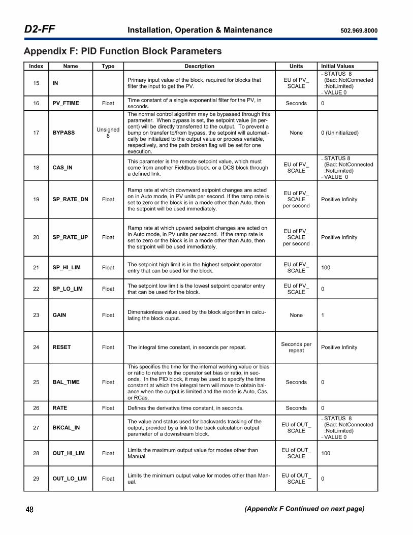
D2-FF Installation, Operation & Maintenance 502.969.8000
(Appendix F Continued on next page)
Appendix F: PID Function Block Parameters
Index Name Type Description Units Initial Values
15 IN Primary input value of the block, required for blocks that filter the input to get the PV.
EU of PV_ SCALE
STATUS 8(Bad::NotConnected:NotLimited)
VALUE 0
16 PV_FTIME Float Time constant of a single exponential filter for the PV, in seconds.
Seconds 0
17 BYPASS Unsigned
8
The normal control algorithm may be bypassed through this parameter. When bypass is set, the setpoint value (in per-cent) will be directly transferred to the output. To prevent a bump on transfer to/from bypass, the setpoint will automati-cally be initialized to the output value or process variable, respectively, and the path broken flag will be set for one execution.
None 0 (Uninitialized)
18 CAS_IN This parameter is the remote setpoint value, which must come from another Fieldbus block, or a DCS block through a defined link.
EU of PV_ SCALE
STATUS 8(Bad::NotConnected:NotLimited)
VALUE 0
19 SP_RATE_DN Float
Ramp rate at which downward setpoint changes are acted on in Auto mode, in PV units per second. If the ramp rate is set to zero or the block is in a mode other than Auto, then the setpoint will be used immediately.
EU of PV_ SCALE
per second
Positive Infinity
20 SP_RATE_UP Float
Ramp rate at which upward setpoint changes are acted on in Auto mode, in PV units per second. If the ramp rate is set to zero or the block is in a mode other than Auto, then the setpoint will be used immediately.
EU of PV_ SCALE
per second
Positive Infinity
21 SP_HI_LIM Float The setpoint high limit is in the highest setpoint operator entry that can be used for the block.
EU of PV_ SCALE
100
22 SP_LO_LIM Float The setpoint low limit is the lowest setpoint operator entry that can be used for the block.
EU of PV_ SCALE
0
23 GAIN Float Dimensionless value used by the block algorithm in calcu-lating the block ouput.
None 1
24 RESET Float The integral time constant, in seconds per repeat. Seconds per
repeat Positive Infinity
25 BAL_TIME Float
This specifies the time for the internal working value or bias or ratio to return to the operator set bias or ratio, in sec-onds. In the PID block, it may be used to specify the time constant at which the integral term will move to obtain bal-ance when the output is limited and the mode is Auto, Cas, or RCas.
Seconds 0
26 RATE Float Defines the derivative time constant, in seconds. Seconds 0
27 BKCAL_IN The value and status used for backwards tracking of the output, provided by a link to the back calculation output parameter of a downstream block.
EU of OUT_ SCALE
STATUS 8(Bad::NotConnected:NotLimited)
VALUE 0
28 OUT_HI_LIM Float Limits the maximum output value for modes other than Manual.
EU of OUT_ SCALE
100
29 OUT_LO_LIM Float Limits the minimum output value for modes other than Man-ual.
EU of OUT_ SCALE
0

www.topworx.com
®
Index Name Type Description Units Initial Values
30 BKCAL_HYS
Float The amount that the block output must change away from its output limit before the limit status is turned off, ex-pressed as a percent of the span of the output.
% 0.5
31 BKCAL_OUT
The output value and status provided to an upstream block for output tracking when the loop is broken or lim-ited, as determined by the status bits. This information is used to provide bumpless transfer to closed loop control and to prevent windup under limited conditions when that becomes possible.
EU of PV_ SCALE
STATUS 0
VALUE 0
32 RCAS_IN Target setpoint and status provided by a supervisory Host to an analog control or output block.
EU of PV_ SCALE
STATUS 8(Bad::NotConnected:NotLimited)
VALUE 0
33 ROUT_IN Target output and status provided by a Host to the control block for use as the output (ROut mode).
EU of OUT_ SCALE
STATUS 8(Bad::NotConnected:NotLimited)
VALUE 0
34 SHED_OPT Unsigned
8 Defines action to be taken on remote control device timeout.
None 0 (Uninitialized)
35 RCAS_OUT Block setpoint and status after ramping - provided to a supervisory Host for back calculation and to allow action to be taken under limiting conditions or mode change.
EU of PV_ SCALE
STATUS 0
VALUE 0
36 ROUT_OUT Block output and status - provided to a Host for back calculation in ROut mode and to allow action to be taken under limited conditions or mode change.
EU of OUT_ SCALE
STATUS 0
VALUE 0
37 TRK_SCALE The high and low scale values, engineering units code, and number of digits to the right of the decimal point as-sociated with TRK_VAL.
None
EU_100 100 EU_0 0
UNITS_INDEX 1342(%)
DECIMAL 0
38 TRK_IN_D This discrete input is used to initiate external tracking of the block output to the value specified by TRL_VAL.
None
STATUS 8(Bad::NotConnected:NotLimited)
VALUE 0
39 TRK_VAL This input is used as the track value when external track-ing is enabled in TRK_IN_D.
None
STATUS 8(Bad::NotConnected:NotLimited)
VALUE 0
40 FF_VAL The feed forward value and status. EU of FF_
SCALE
STATUS 0
VALUE 0
41 FF_SCALE The feed forward input high and low scale values, engi-neering units code, and number of digits to the right of the decimal point.
None
EU_100 100 EU_0 0
UNITS_INDEX 1342(%)
DECIMAL 0
42 FF_GAIN Float The gain that the feed forward input is multiplied by be-fore it is added to the calculated control output.
None 0
43 UPDATE_ EVT
This alert is generated by any change to the static data. None
UNACKNOWLEDGED 0 (Uninitialized)
UPDATE_STATE 0 (Uninitialized)
TIME_STAMP 0
STATIC_REVISION 0 RELATIVE_INDEX 0
44 BLOCK_ ALM
The block alarm is used for all configuration, hardware, connec-tion failure or system problems in the block. The cause of the alert is entered in the subcode field. The first alert to become active will set the Active status in the Status attribute. As soon as the Unreported status is cleared by the alert reporting task, anoth-er block alert may be reported without clearing the Active status, if the subcode has changed.
None
UNACKNOWLEDGED 0 (Uninitialized)
ALARM_STATE 0 (Uninitialized)
TIME_STAMP 0
SUB_CODE 0 (Other) VALUE 0
(Appendix F Continued on next page)
Appendix F: PID Function Block Parameters (Continued)

D2-FF Installation, Operation & Maintenance 502.969.8000
(Appendix F Continued on next page)
Appendix F: PID Function Block Parameters (Continued)
Index Name Type Description Units Initial Values
45 ALARM_ SUM
The current alert status, unacknowledged states, unreported states, and disabled states of the alarms associated with the function block.
None
CURRENT 0 UNACKNOWLEDGED 0 UNREPORTED 0 DISABLED 0
46 ACK_ OPTION
Bit String Selection of whether alarms associated with the function block will be automatically acknowledged.
None 0
47 ALARM_ HYS
Float Amount the PV must return within the alarm limits before the alarm condition clears. Alarm hysteresis expressed as a percent of the span of the PV.
% 0.5
48 HI_HI_PRI Unsigned 8 Priority of the high high alarm None 0
49 HI_HI_LIM Float The setting for high high alarm in engineering units. EU of PV_
SCALE Positive Infinity
50 HI_PRI Unsigned 8 Priority of the high alarm. None 0
51 HI_LIM Float The setting for high alarm in engineering units. EU of PV_
SCALE Positive Infinity
52 LO_PRI Unsigned 8 Priority of the low alarm. None 0
53 LO_LIM Float The setting for the low alarm in engineering units. EU of PV_
SCALE Negative Infinity
54 LO_LO_PRI Unsigned 8 Priority of the low low alarm. None 0
55 LO_LO_ LIM
Float The setting of the low low alarm in engineering units. EU of PV_
SCALE Negative Infinity
56 DV_HI_PRI Unsigned 8 Priority of the high deviation alarm. None 0
57 DV_HI_LIM Float The setting of the high deviation alarm limit in engineering units.
EU of PV_ SCALE
Positive Infinity
58 DV_LO_PRI Unsigned 8 Priority of the low deviation alarm. None 0
59 DV_LO_ LIM
Float The setting of the low deviation alarm limit in engineering units.
EU of PV_ SCALE
Negative Infinity
60 HI_HI_ALM The status for high high alarm and its associated time stamp. None
UNACKNOWLEDGED 0(Uninitialized)
ALARM_STATE 0(Uninitialized)
TIME_STAMP 0
SUB_CODE 0 (Other) VALUE 0
61 HI_ALM The status for high alarm and its associated time stamp. None
UNACKNOWLEDGED 0(Uninitialized)
ALARM_STATE 0(Uninitialized)
TIME_STAMP 0
SUB_CODE 0 (Other) VALUE 0
62 LO_ALM The status of the low alarm and its associated time stamp. None
UNACKNOWLEDGED 0(Uninitialized)
ALARM_STATE 0(Uninitialized)
TIME_STAMP 0
SUB_CODE 0 (Other) VALUE 0
63 LO_LO_ ALM
The status of the low low alarm and its associated time stamp.
None
UNACKNOWLEDGED 0(Uninitialized)
ALARM_STATE 0(Uninitialized)
TIME_STAMP 0
SUB_CODE 0 (Other) VALUE 0
64 DV_HI_ ALM
The status and time stamp associated with the high deviation alarm.
None
UNACKNOWLEDGED 0(Uninitialized)
ALARM_STATE 0(Uninitialized)
TIME_STAMP 0
SUB_CODE 0 (Other) VALUE 0
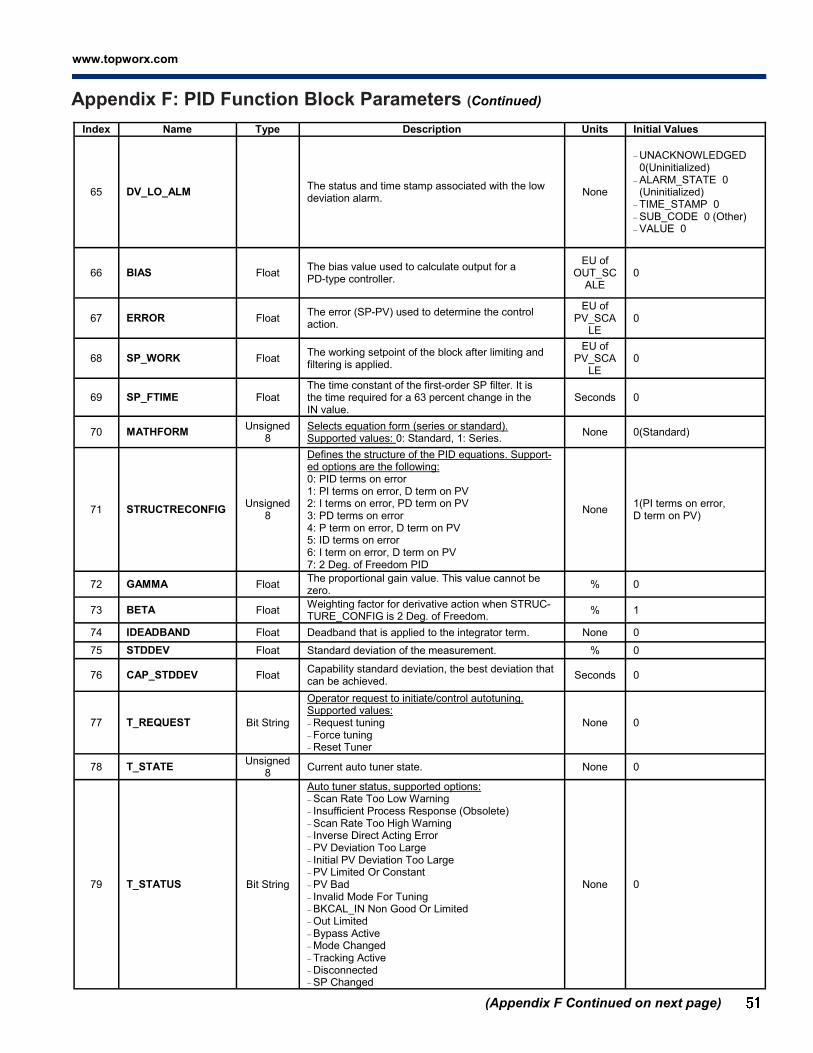
www.topworx.com
®
Index Name Type Description Units Initial Values
65 DV_LO_ALM The status and time stamp associated with the low deviation alarm.
None
UNACKNOWLEDGED 0(Uninitialized)
ALARM_STATE 0(Uninitialized)
TIME_STAMP 0
SUB_CODE 0 (Other) VALUE 0
66 BIAS Float The bias value used to calculate output for a PD-type controller.
EU of OUT_SC
ALE 0
67 ERROR Float The error (SP-PV) used to determine the control action.
EU of PV_SCA
LE 0
68 SP_WORK Float The working setpoint of the block after limiting and filtering is applied.
EU of PV_SCA
LE
0
69 SP_FTIME Float The time constant of the first-order SP filter. It is the time required for a 63 percent change in the IN value.
Seconds 0
70 MATHFORM Unsigned
8
Selects equation form (series or standard). Supported values: 0: Standard, 1: Series.
None 0(Standard)
71 STRUCTRECONFIG Unsigned
8
Defines the structure of the PID equations. Support-ed options are the following: 0: PID terms on error 1: PI terms on error, D term on PV 2: I terms on error, PD term on PV 3: PD terms on error 4: P term on error, D term on PV 5: ID terms on error 6: I term on error, D term on PV 7: 2 Deg. of Freedom PID
None 1(PI terms on error, D term on PV)
72 GAMMA Float The proportional gain value. This value cannot be zero.
% 0
73 BETA Float Weighting factor for derivative action when STRUC-TURE_CONFIG is 2 Deg. of Freedom.
% 1
74 IDEADBAND Float Deadband that is applied to the integrator term. None 0
75 STDDEV Float Standard deviation of the measurement. % 0
76 CAP_STDDEV Float Capability standard deviation, the best deviation that can be achieved.
Seconds 0
77 T_REQUEST Bit String
Operator request to initiate/control autotuning. Supported values: Request tuning
Force tuning Reset Tuner
None 0
78 T_STATE Unsigned
8 Current auto tuner state. None 0
79 T_STATUS Bit String
Auto tuner status, supported options: Scan Rate Too Low Warning
Insufficient Process Response (Obsolete) Scan Rate Too High Warning Inverse Direct Acting Error PV Deviation Too Large
Initial PV Deviation Too Large PV Limited Or Constant PV Bad
Invalid Mode For Tuning BKCAL_IN Non Good Or Limited
Out Limited
Bypass Active Mode Changed
Tracking Active
Disconnected SP Changed
None 0
(Appendix F Continued on next page)
Appendix F: PID Function Block Parameters (Continued)
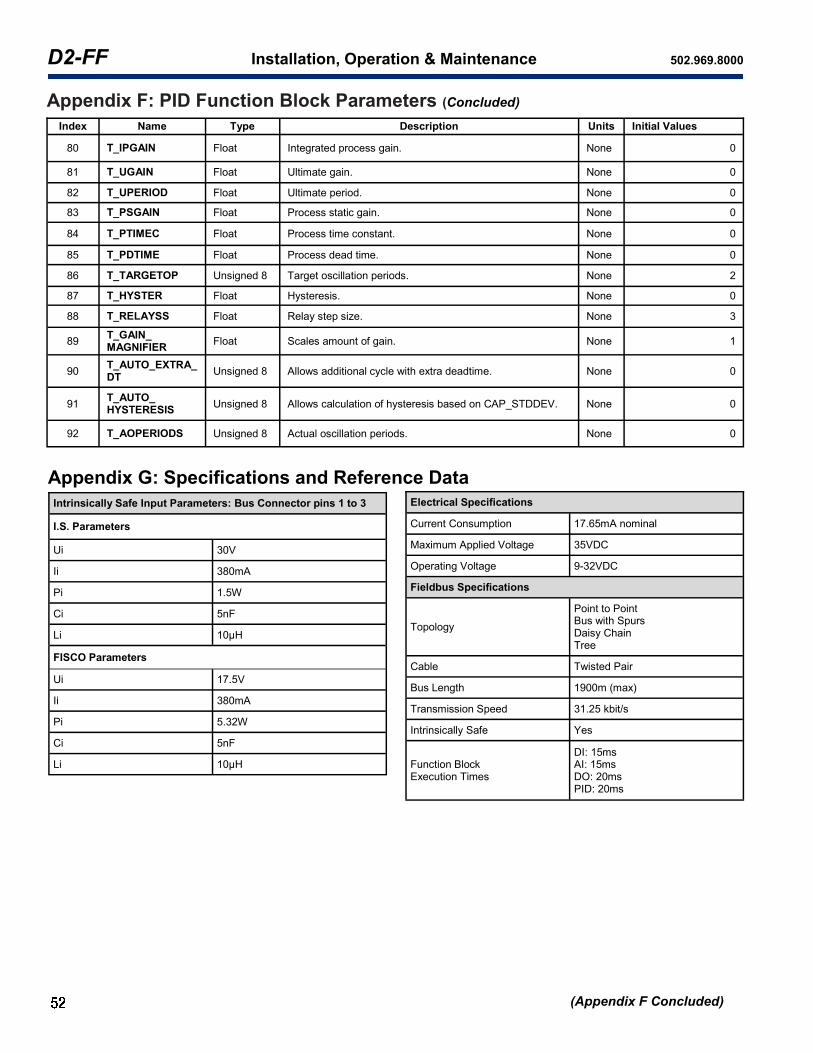
D2-FF Installation, Operation & Maintenance 502.969.8000
(Appendix F Concluded)
Appendix F: PID Function Block Parameters (Concluded)
Index Name Type Description Units Initial Values
80 T_IPGAIN Float Integrated process gain. None 0
81 T_UGAIN Float Ultimate gain. None 0
82 T_UPERIOD Float Ultimate period. None 0
83 T_PSGAIN Float Process static gain. None 0
84 T_PTIMEC Float Process time constant. None 0
85 T_PDTIME Float Process dead time. None 0
86 T_TARGETOP Unsigned 8 Target oscillation periods. None 2
87 T_HYSTER Float Hysteresis. None 0
88 T_RELAYSS Float Relay step size. None 3
89 T_GAIN_ MAGNIFIER
Float Scales amount of gain. None 1
90 T_AUTO_EXTRA_DT
Unsigned 8 Allows additional cycle with extra deadtime. None 0
91 T_AUTO_ HYSTERESIS
Unsigned 8 Allows calculation of hysteresis based on CAP_STDDEV. None 0
92 T_AOPERIODS Unsigned 8 Actual oscillation periods. None 0
Appendix G: Specifications and Reference Data
Intrinsically Safe Input Parameters: Bus Connector pins 1 to 3
I.S. Parameters
Ui 30V
Ii 380mA
Pi 1.5W
Ci 5nF
Li 10μH
FISCO Parameters
Ui 17.5V
Ii 380mA
Pi 5.32W
Ci 5nF
Li 10μH
Electrical Specifications
Current Consumption 17.65mA nominal
Maximum Applied Voltage 35VDC
Operating Voltage 9-32VDC
Fieldbus Specifications
Topology
Point to Point Bus with Spurs Daisy Chain Tree
Cable Twisted Pair
Bus Length 1900m (max)
Transmission Speed 31.25 kbit/s
Intrinsically Safe Yes
Function Block Execution Times
DI: 15ms AI: 15ms DO: 20ms PID: 20ms

www.topworx.com
®
(Appendix F Concluded)
Certifications & Approvals
Safe Use Special Conditions of Safe Use (All installations) Clean only with a damp cloth to prevent possibility of electrostatic discharge. For Explosion Proof installations, the internal ground connection shall be used and the external ground connection, if supplied in addition, is supplemental bonding allowed where local authorities permit, or is required. When installing with a third party listed nipple-mount solenoid, it is the responsibility of the installer to provide fittings, and apparatus, suitable for the area classification in accordance with the National Electrical Code. All cable entry devices or conduit stopping boxes shall be certified in type of explosion protection ‘d’, suitable for the conditions of use and correctly installed. The IIC enclosures are excluded from use in carbon disulphide atmospheres. The air pressure to the valve block, when fitted, shall not exceed 7bar. For
ambient temperatures higher than 110 C, the IP66/IP67
protection level is not guaranteed.
Preventative Maintenance The TopWorx™ is designed to operate for one million cycles without servicing. Call TopWorx when you are approaching this milestone for a preventative maintenance kit and instructions.
PESO Ex ia IIC T* Gb; Ex tb IIIC T* Db Ex ib IIC T* GB; Ex tb IIIC T* Db IECEx SIR 14.0078X / Sira 14ATEX2241X IECEx BAS 11.0022X / Baseefa 11ATEX0035X (FF) USL/CNL Class I, Div 1, GrABCD UL File E125326 EAC RU C-US.ГБ08.В.01717 NEPSI GYJ13.1297X InMetro NCC12.1260X, NCC12.0767X PESO P347552
Ex d IIC T* Gb or Ex d IIB+H2 T* Gb; Ex tb IIC T* Db IECEx SIR 07.0093X / Sira 07ATEX1273X USL/CNL Class I, Div 1, GrCD; Class II, Div 1, GrEFG UL File E125326 EAC RU C-US.ГБ08.В.01717 KOSHA 13-AV4BO-0003X & 14-AV4BO-0073X NEPSI GYJ13.1295X InMetro NCC 12.1138X PESO P353049
Ex e MB IIC T* Gb; Ex tb IIIC T* Db IECEx SIR 09.0088X / Sira 09ATEX3209X (DXR)
Ex nA nC IIC T* Gc; Ex tb IIIC T* Dc IECEx BAS 11.0023X / Baseefa 11ATEX0036X (FF) USL/CNL Class I, Div 2, GrABCD; Class II, Div 2, GrFG UL File E125326
USL/CNL General Purpose UL File E359150
Environmental Ratings: Type 4, 4X; IP 66/67
Conformance to Directives: ATEX 2014/34/EU, EMC 2004/108/EC, LVD 2006/95/EC
*Operating and Ambient temperature ratings vary depending on bus/sensor option(s), reference certificate for specif-ic markings available.
Consult factory for certification questions or to request a custom product.

D2-FF Installation, Operation & Maintenance 502.969.8000
Pilot Replacement Kits
AV-SP20PMRK Piezo pilot/manifold replacement kit
Spool Valve Replacement Assemblies
AV-AB1A20 ASCO 8551 Spool Valve, Fail Open/Closed, Aluminum
AV-AB1620 ASCO 8551 Spool Valve, Fail Open/Closed, SST
AV-AV2A20 ASCO 8551 Spool Valve, Fail Last, Aluminum
AV-AB2620 ASCO 8551 Spool Valve, Fail Last, SST
AV-AB1A30 ASCO 8553 Spool Valve, Fail Open/Closed, Aluminum
AV-AB1630 ASCO 8553 Spool Valve, Fail Open/Closed, SST
AV-AB2A30 ASCO 8553 Spool Valve, Fail Last, Aluminum
AV-AB2630 ASCO 8533 Spool Valve, Fail Last, SST
No Approvals (DXP/DXS) *DXR Enclosure limited to -40°C to 80°C
Option Switch Description Switchbox (NO Integrated Solenoid) Switchbox (WITH Integrated Solenoid)
FF Foundation Fieldbus -40 to +80°C Consult Factory
FL Foundation Fieldbus w/GO -40 to +80°C Consult Factory
FP FF w/GO and potentiometer -40 to +80°C Consult Factory
TopWorx™ D-Series Replacement Part Number List
Recommended Operating Temperatures

www.topworx.com
®
Notes:

ES-02512-1 R8
www.topworx.com
GLOBAL SUPPORT OFFICES
North America
Middle East
Asia-Pacific
Africa
Europe