topology optimization using nx nastran & simcenter · nx nastran results • for each subcase,...
TRANSCRIPT
Topology Optimization using
NX Nastran & SimcenterGuy Wills
Simcenter 3D Topology Optimization Product Manager
Realize innovation.Restricted © Siemens AG 2017

Unrestricted © Siemens AG 20182017.MM.DDPage 2 Siemens PLM Software
Topology Optimization for Analysts – Highlights
• Created to enable CAE Analysts to use advanced CAE and optimization
functionality to execute design concept studies.
• Topology Optimization embedded into NX Nastran. Based on industry proven
Optimization architecture (SOL200).
• Topology Optimization workflow integrated into Simcenter 3D Engineering
Desktop to aid the model construction and post processing of the results.
• Multi-discipline optimization with a mix of solution types in the same
optimization.
• Geometry shape control (Manufacturing Constraints).
• Lattice zone prediction – Designing for Lattices.
• Smoothed facet model
available to guide further
design work.
Mesh with
Lattice
Changes included
in CAD with
Lattice
Unrestricted © Siemens AG 20182017.MM.DDPage 3 Siemens PLM Software
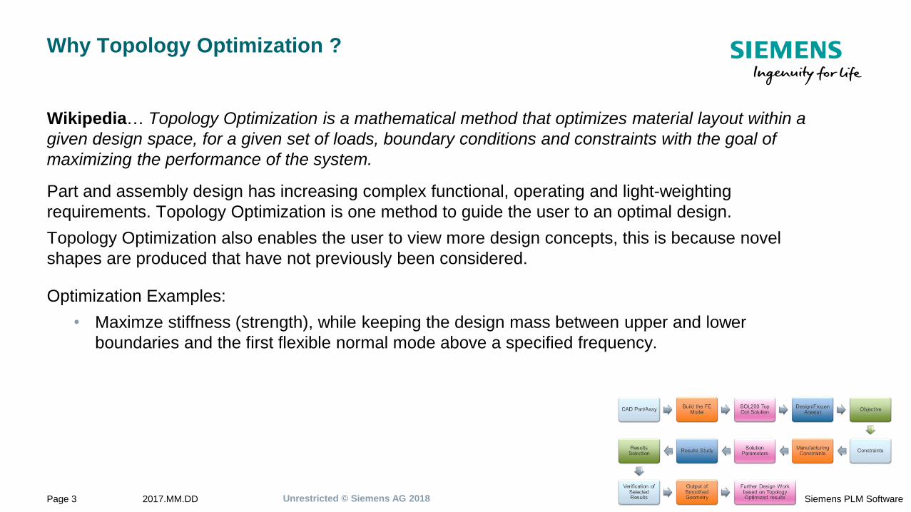
Why Topology Optimization ?
Wikipedia… Topology Optimization is a mathematical method that optimizes material layout within a
given design space, for a given set of loads, boundary conditions and constraints with the goal of
maximizing the performance of the system.
Part and assembly design has increasing complex functional, operating and light-weighting
requirements. Topology Optimization is one method to guide the user to an optimal design.
Topology Optimization also enables the user to view more design concepts, this is because novel
shapes are produced that have not previously been considered.
Optimization Examples:
• Maximze stiffness (strength), while keeping the design mass between upper and lower
boundaries and the first flexible normal mode above a specified frequency.
Unrestricted © Siemens AG 20182017.MM.DDPage 4 Siemens PLM Software
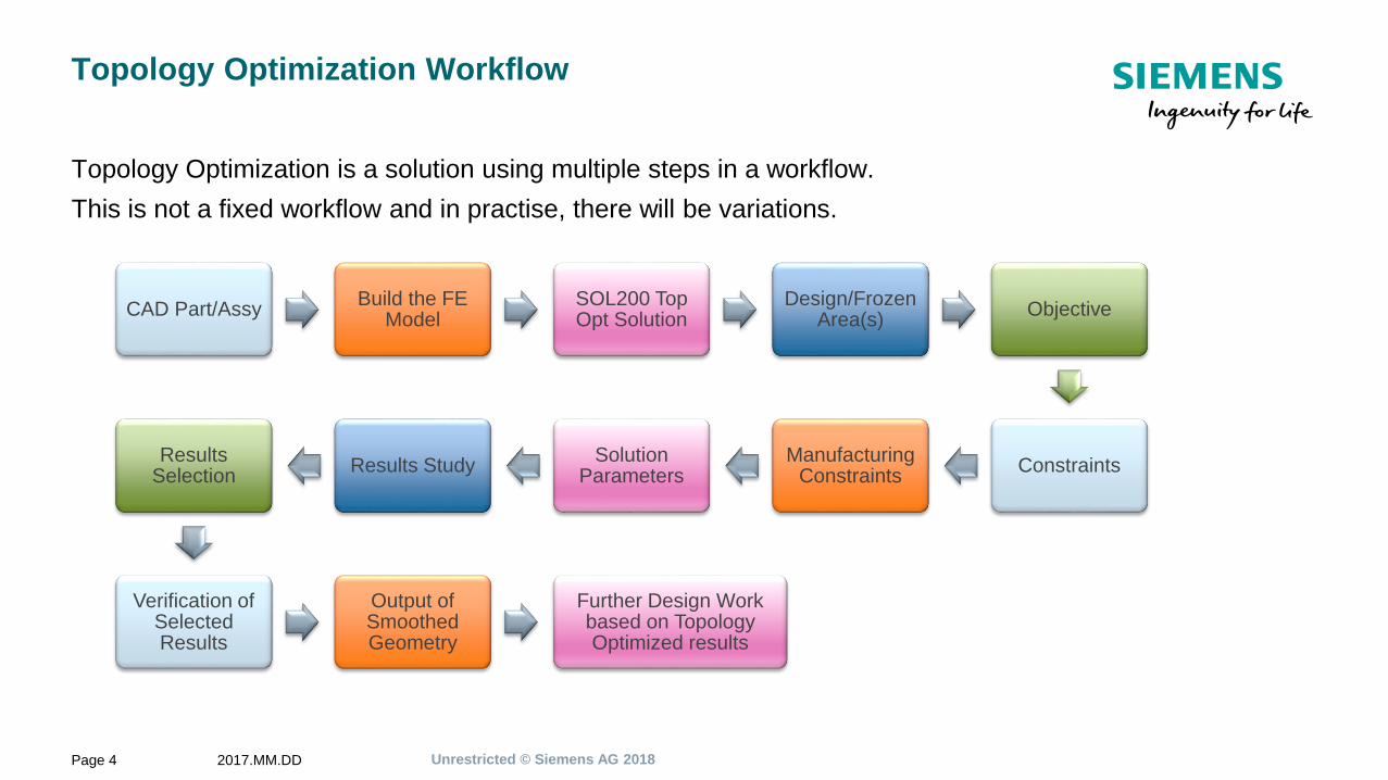
Topology Optimization Workflow
Topology Optimization is a solution using multiple steps in a workflow.
This is not a fixed workflow and in practise, there will be variations.
CAD Part/AssyBuild the FE
ModelSOL200 Top Opt Solution
Design/Frozen Area(s)
Objective
ConstraintsManufacturing
ConstraintsSolution
ParametersResults Study
Results Selection
Verification of Selected Results
Output of Smoothed Geometry
Further Design Work based on Topology Optimized results
Unrestricted © Siemens AG 20182017.MM.DDPage 5 Siemens PLM Software
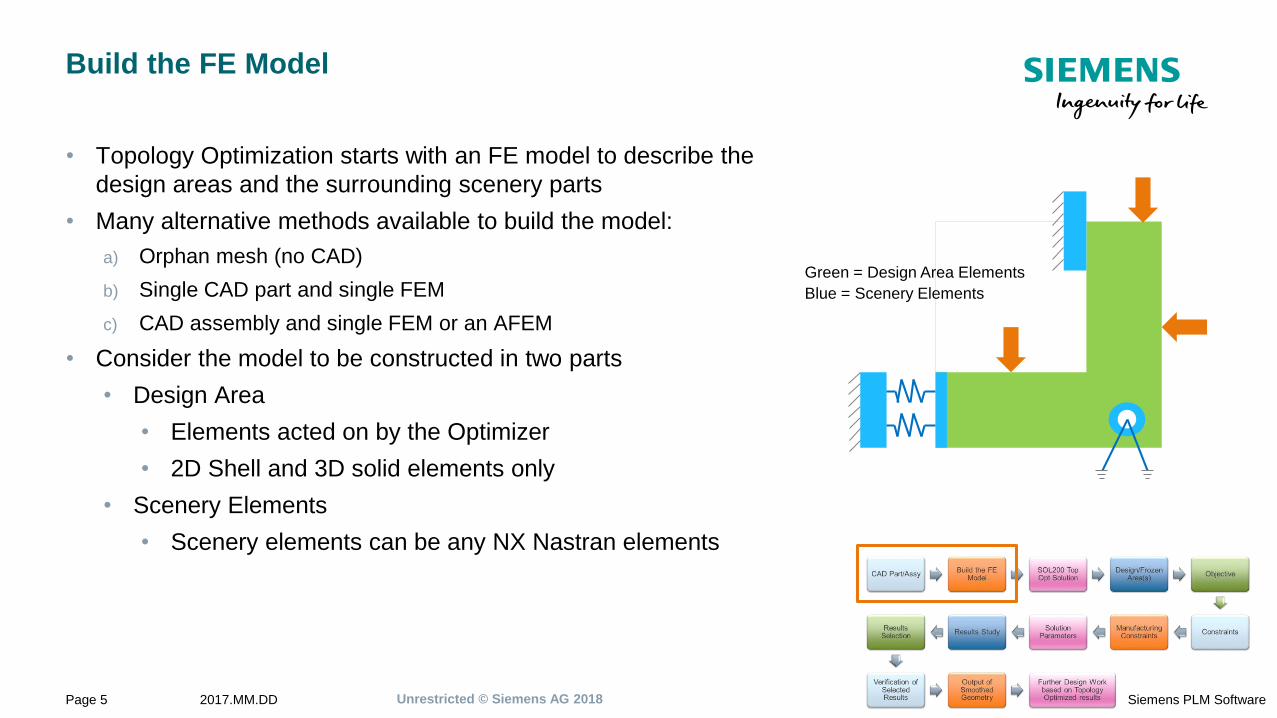
Build the FE Model
• Topology Optimization starts with an FE model to describe the
design areas and the surrounding scenery parts
• Many alternative methods available to build the model:
a) Orphan mesh (no CAD)
b) Single CAD part and single FEM
c) CAD assembly and single FEM or an AFEM
• Consider the model to be constructed in two parts
• Design Area
• Elements acted on by the Optimizer
• 2D Shell and 3D solid elements only
• Scenery Elements
• Scenery elements can be any NX Nastran elements
Green = Design Area Elements
Blue = Scenery Elements
Unrestricted © Siemens AG 20182017.MM.DDPage 6 Siemens PLM Software
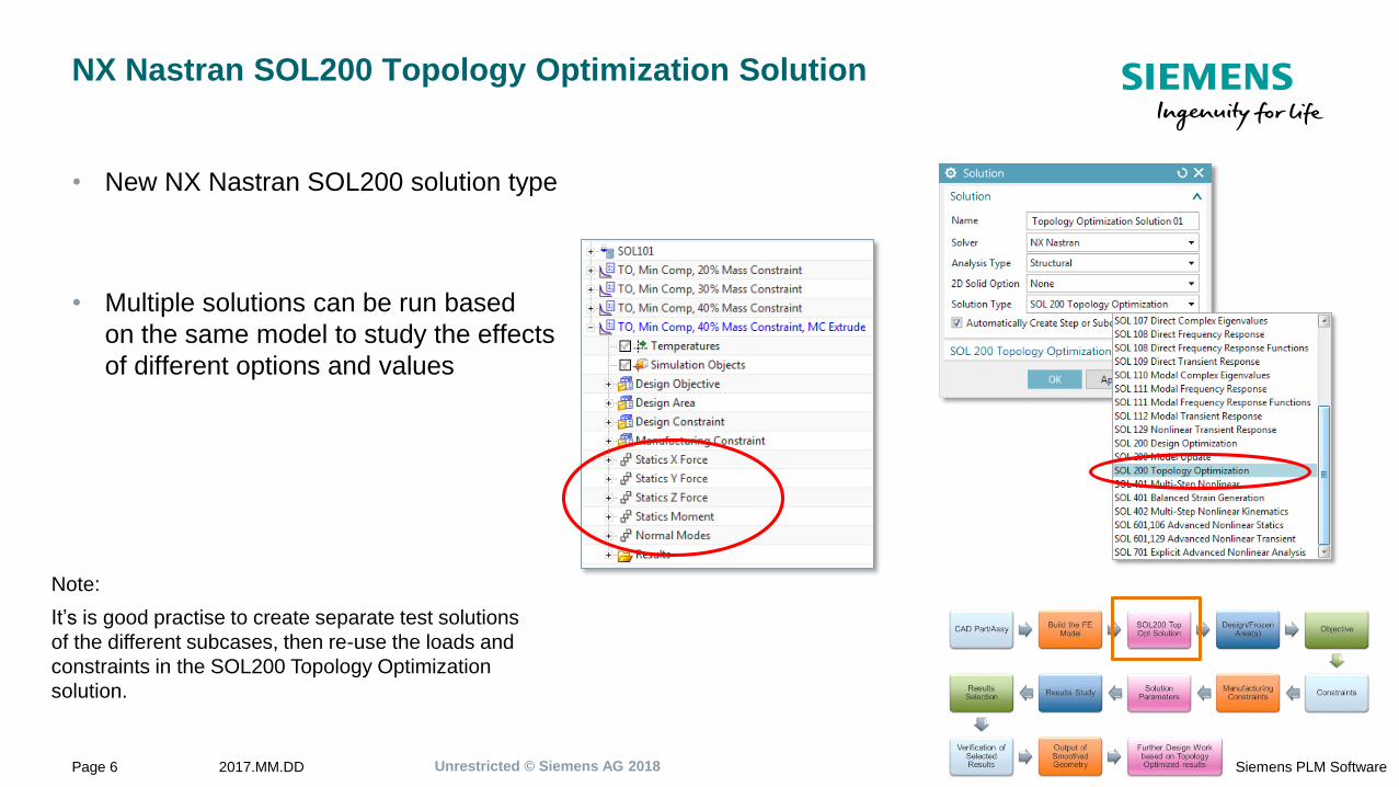
NX Nastran SOL200 Topology Optimization Solution
• New NX Nastran SOL200 solution type
• Multiple solutions can be run based
on the same model to study the effects
of different options and values
Note:
It’s is good practise to create separate test solutions
of the different subcases, then re-use the loads and
constraints in the SOL200 Topology Optimization
solution.
Unrestricted © Siemens AG 20182017.MM.DDPage 7 Siemens PLM Software
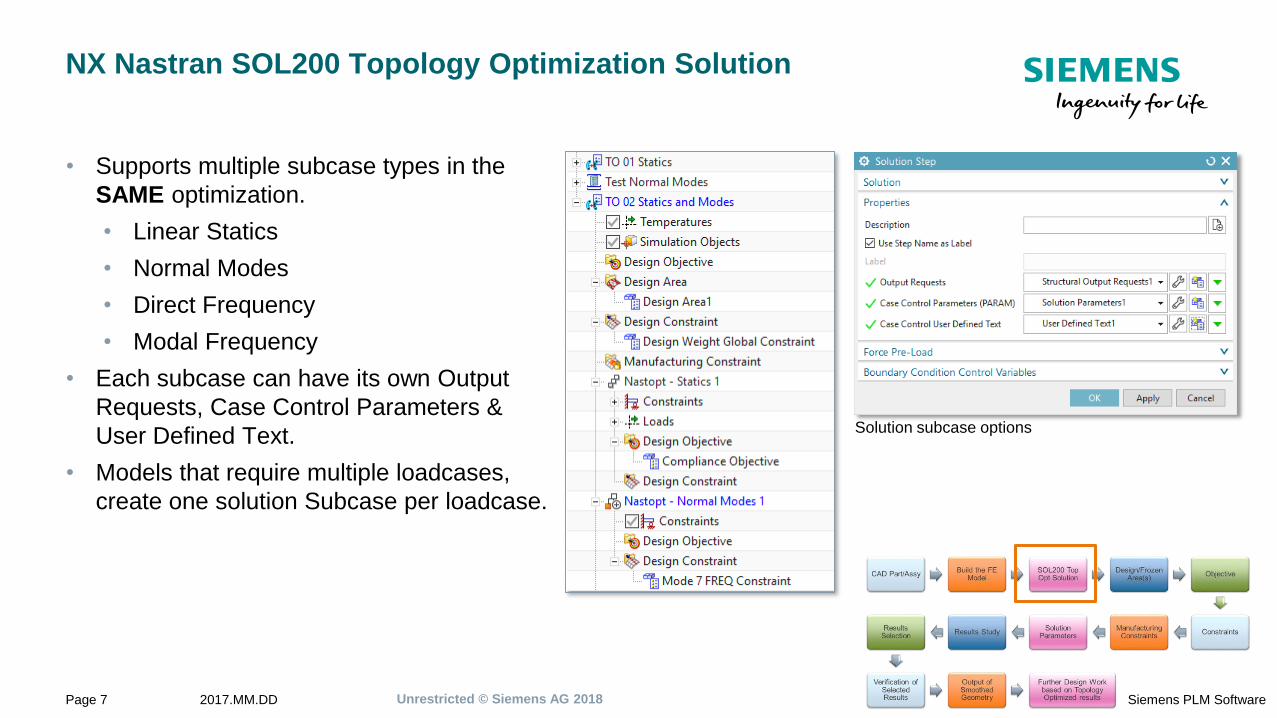
NX Nastran SOL200 Topology Optimization Solution
• Supports multiple subcase types in the
SAME optimization.
• Linear Statics
• Normal Modes
• Direct Frequency
• Modal Frequency
• Each subcase can have its own Output
Requests, Case Control Parameters &
User Defined Text.
• Models that require multiple loadcases,
create one solution Subcase per loadcase.
Solution subcase options
Unrestricted © Siemens AG 20182017.MM.DDPage 8 Siemens PLM Software
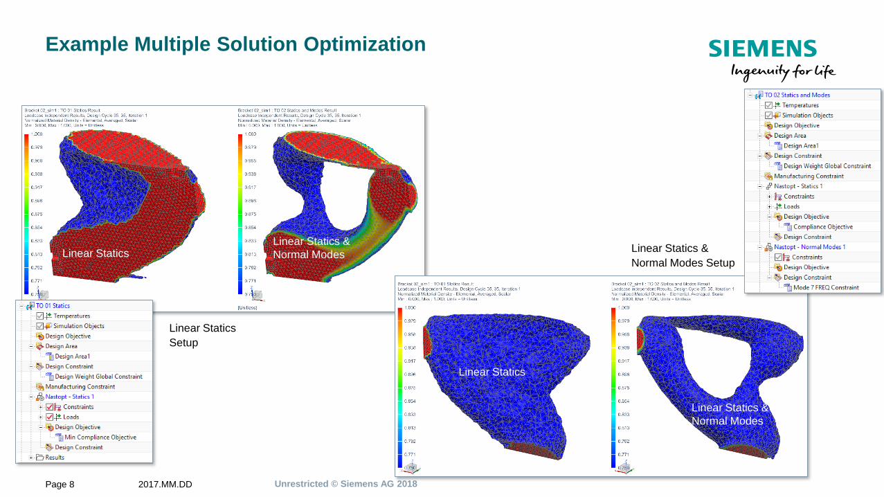
Example Multiple Solution Optimization
Linear Statics Linear Statics &
Normal Modes
Linear Statics
Setup
Linear Statics &
Normal Modes Setup
Linear Statics &
Normal Modes
Linear Statics
Unrestricted © Siemens AG 20182017.MM.DDPage 9 Siemens PLM Software
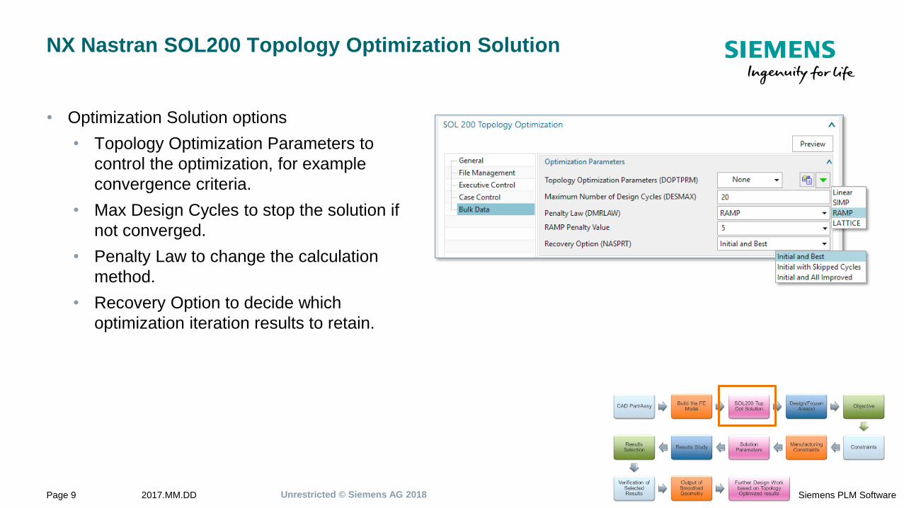
NX Nastran SOL200 Topology Optimization Solution
• Optimization Solution options
• Topology Optimization Parameters to
control the optimization, for example
convergence criteria.
• Max Design Cycles to stop the solution if
not converged.
• Penalty Law to change the calculation
method.
• Recovery Option to decide which
optimization iteration results to retain.
Unrestricted © Siemens AG 20182017.MM.DDPage 10 Siemens PLM Software
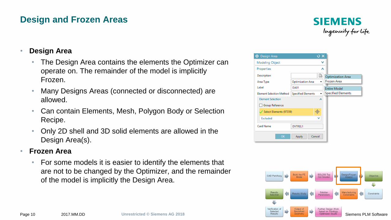
Design and Frozen Areas
• Design Area
• The Design Area contains the elements the Optimizer can
operate on. The remainder of the model is implicitly
Frozen.
• Many Designs Areas (connected or disconnected) are
allowed.
• Can contain Elements, Mesh, Polygon Body or Selection
Recipe.
• Only 2D shell and 3D solid elements are allowed in the
Design Area(s).
• Frozen Area
• For some models it is easier to identify the elements that
are not to be changed by the Optimizer, and the remainder
of the model is implicitly the Design Area.
Unrestricted © Siemens AG 20182017.MM.DDPage 11 Siemens PLM Software
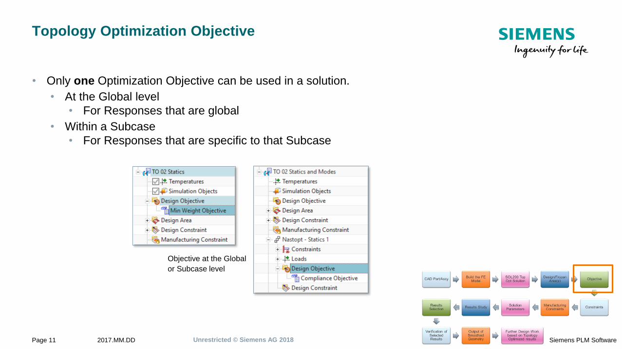
Topology Optimization Objective
• Only one Optimization Objective can be used in a solution.
• At the Global level
• For Responses that are global
• Within a Subcase
• For Responses that are specific to that Subcase
Objective at the Global
or Subcase level
Unrestricted © Siemens AG 20182017.MM.DDPage 12 Siemens PLM Software
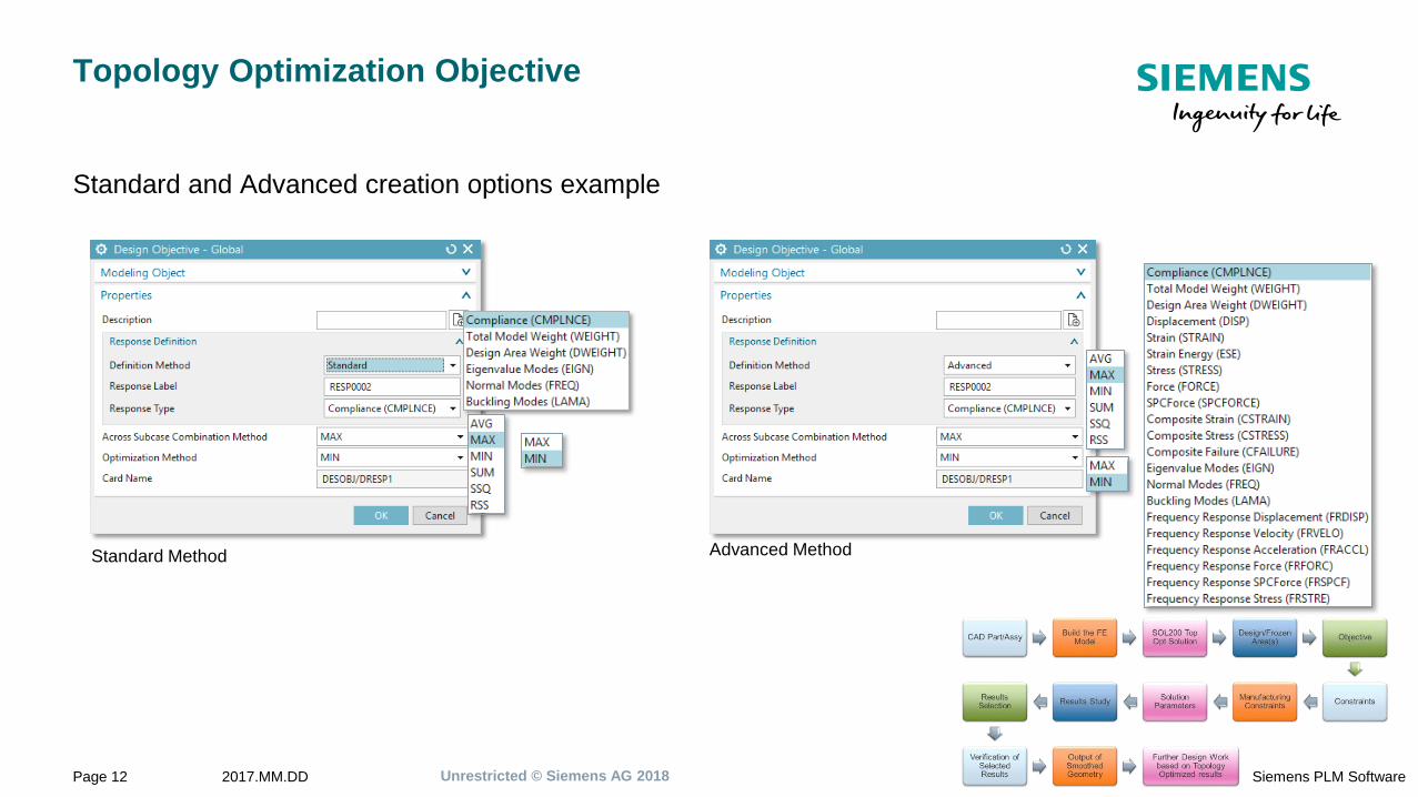
Topology Optimization Objective
Standard and Advanced creation options example
Standard Method Advanced Method
Unrestricted © Siemens AG 20182017.MM.DDPage 13 Siemens PLM Software
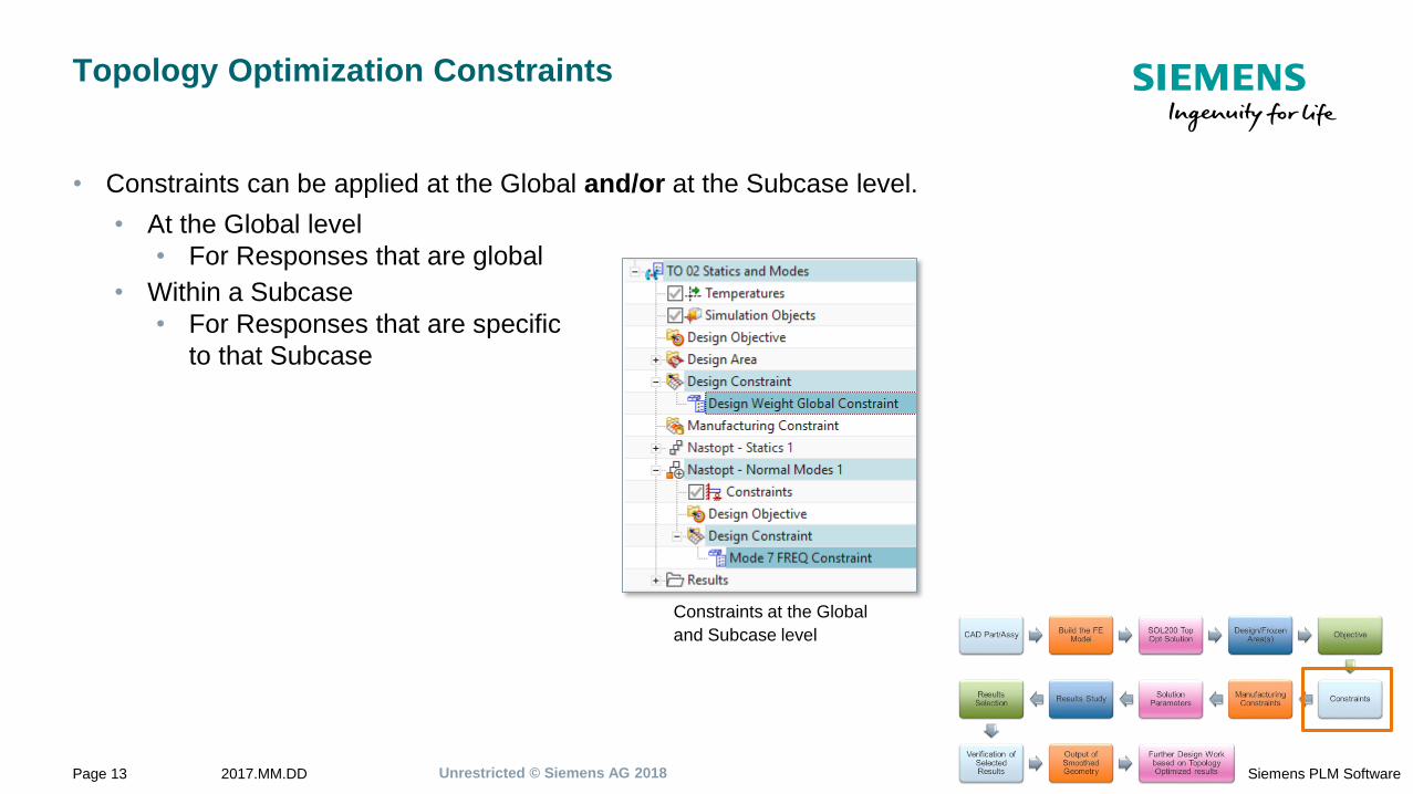
Topology Optimization Constraints
• Constraints can be applied at the Global and/or at the Subcase level.
• At the Global level
• For Responses that are global
• Within a Subcase
• For Responses that are specific
to that Subcase
Constraints at the Global
and Subcase level
Unrestricted © Siemens AG 20182017.MM.DDPage 14 Siemens PLM Software
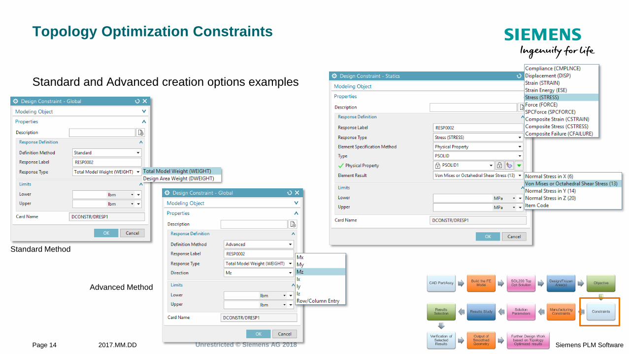
Topology Optimization Constraints
Standard and Advanced creation options examples
Standard Method
Advanced Method
Unrestricted © Siemens AG 20182017.MM.DDPage 15 Siemens PLM Software
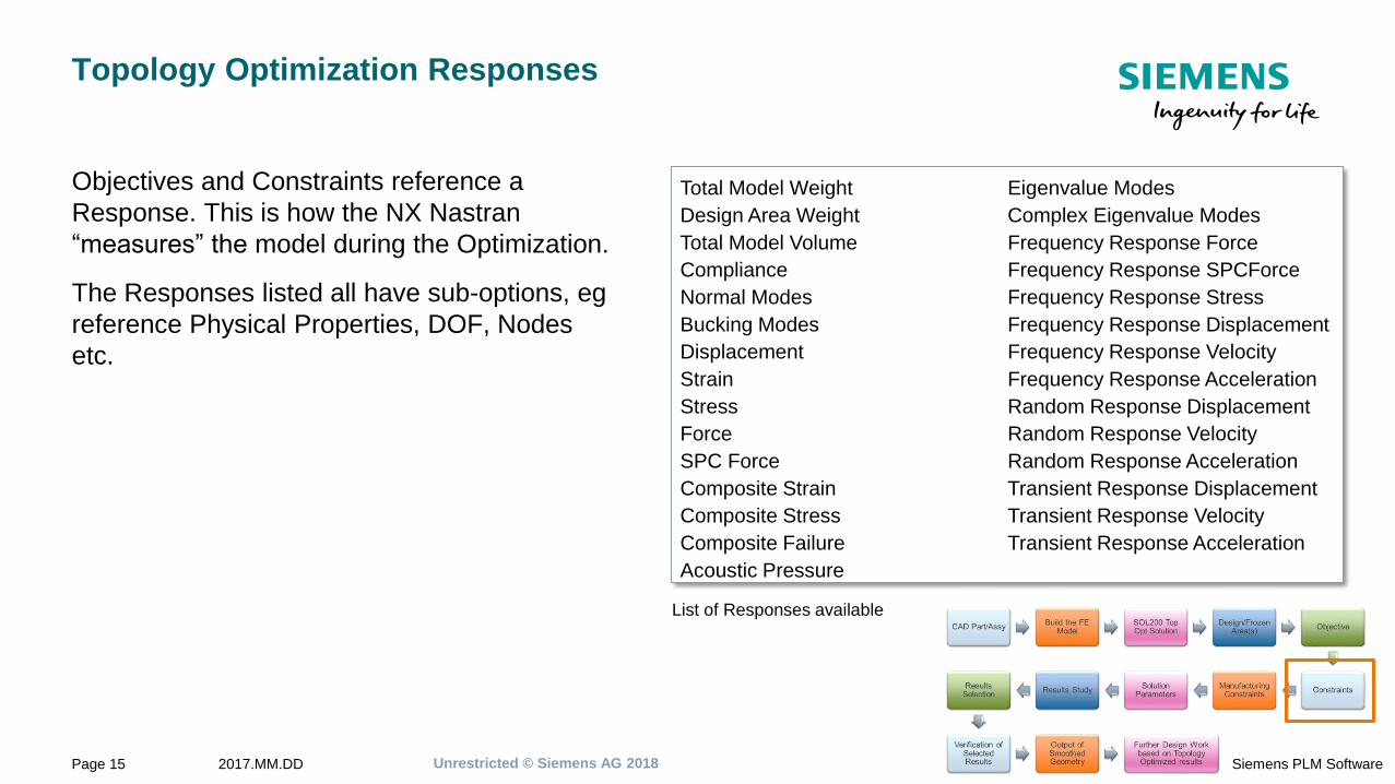
Topology Optimization Responses
Objectives and Constraints reference a
Response. This is how the NX Nastran
“measures” the model during the Optimization.
The Responses listed all have sub-options, eg
reference Physical Properties, DOF, Nodes
etc.
Total Model Weight
Design Area Weight
Total Model Volume
Compliance
Normal Modes
Bucking Modes
Displacement
Strain
Stress
Force
SPC Force
Composite Strain
Composite Stress
Composite Failure
Acoustic Pressure
Eigenvalue Modes
Complex Eigenvalue Modes
Frequency Response Force
Frequency Response SPCForce
Frequency Response Stress
Frequency Response Displacement
Frequency Response Velocity
Frequency Response Acceleration
Random Response Displacement
Random Response Velocity
Random Response Acceleration
Transient Response Displacement
Transient Response Velocity
Transient Response Acceleration
List of Responses available
Unrestricted © Siemens AG 20182017.MM.DDPage 16 Siemens PLM Software
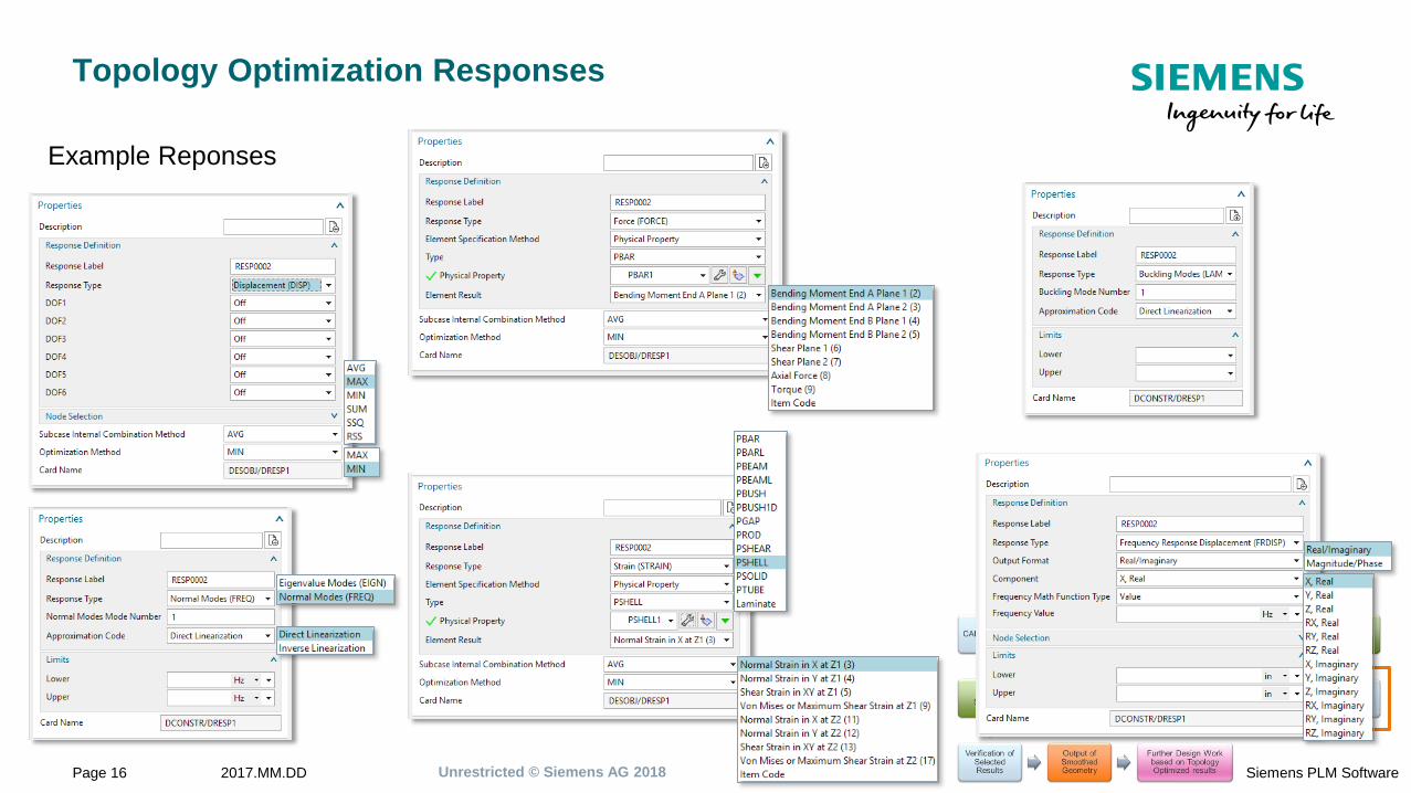
Topology Optimization Responses
Example Reponses

Unrestricted © Siemens AG 20182017.MM.DDPage 17 Siemens PLM Software
Advanced Objective and Constraint Construction
NX Nastran provides the following cards that can be used to create more complex
constructions for the Objective and Constraints
NX Nastran Card Section Description
SET Control List of DRESP1 responses.
DRSPAN Control Exclusively assigns a SET of DRESP1 responses to a specific subcase.
DRESP2 Bulk Defines equation responses that are used for the objective and/or design constraints.
DRESP3 Bulk Defines responses to be evaluated in an external user-supplied program.
DEQTN Bulk Defines one or more equations.
DLINK Bulk Relates one design variable to one or more other design variables.
DSCREEN Bulk Defines screening data for constraint deletion.
DESVAR Bulk Defines a design variable.
DTABLE Bulk Defines a table of real constants that are used in equations.
Unrestricted © Siemens AG 20182017.MM.DDPage 18 Siemens PLM Software
Advanced Objective and Constraint Construction
Examples:
• Taking the Compliance response from 3 subcases and make the sum the Objective.
• Taking the Displacement response from 3 subcases and averaging them as a global Constraint.
• Introduce a variable that is intendant to the model data.
• Introduce a table of constants to be used in multiple equations.
Unrestricted © Siemens AG 20182017.MM.DDPage 19 Siemens PLM Software
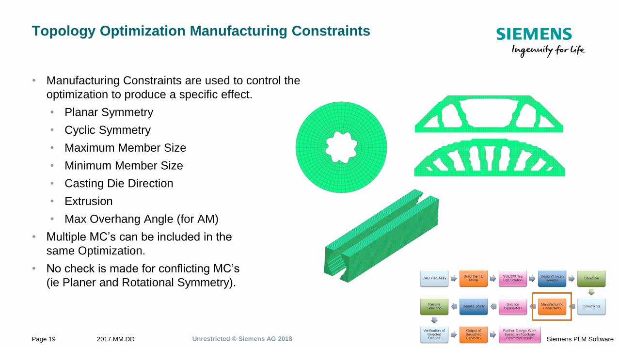
Topology Optimization Manufacturing Constraints
• Manufacturing Constraints are used to control the
optimization to produce a specific effect.
• Planar Symmetry
• Cyclic Symmetry
• Maximum Member Size
• Minimum Member Size
• Casting Die Direction
• Extrusion
• Max Overhang Angle (for AM)
• Multiple MC’s can be included in the
same Optimization.
• No check is made for conflicting MC’s
(ie Planer and Rotational Symmetry).
Unrestricted © Siemens AG 20182017.MM.DDPage 20 Siemens PLM Software
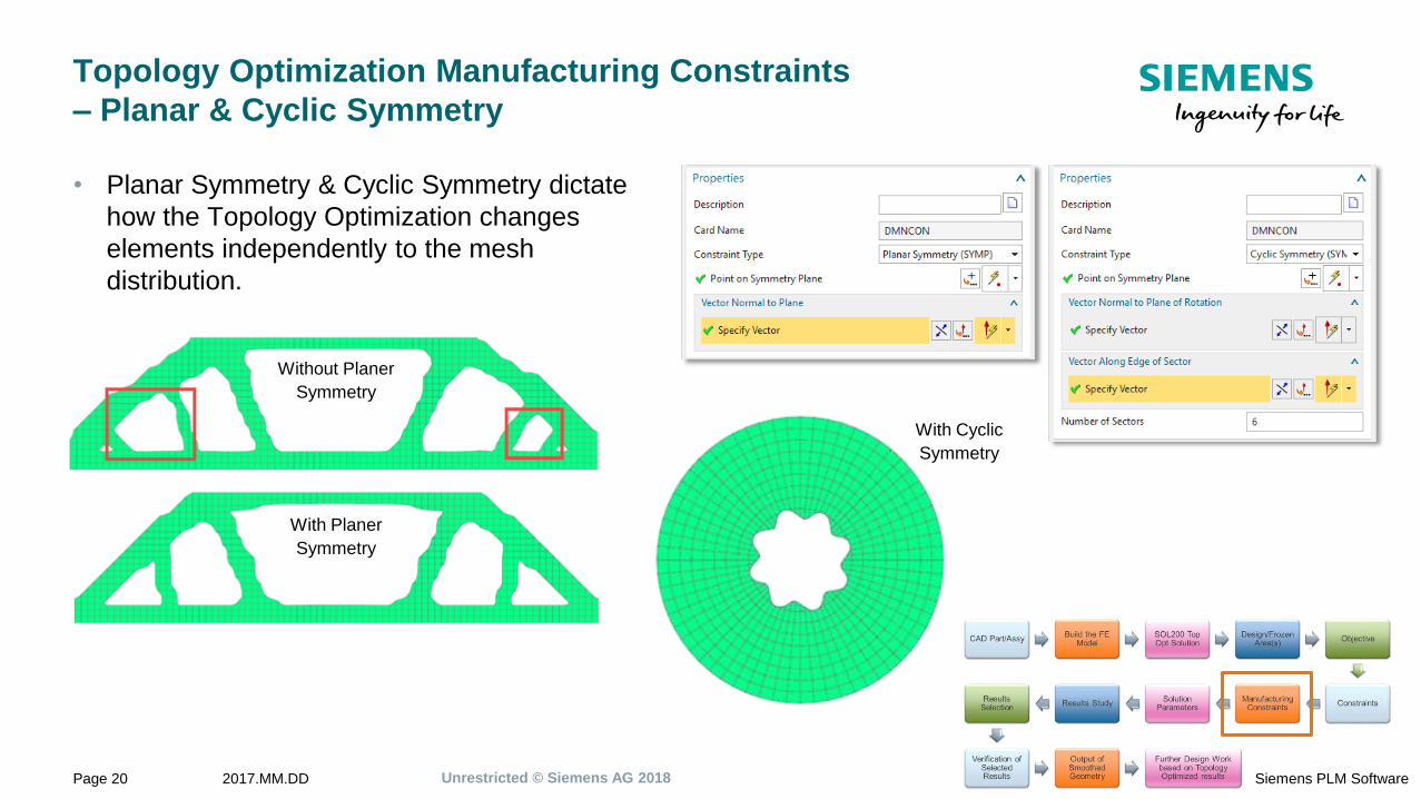
Topology Optimization Manufacturing Constraints
– Planar & Cyclic Symmetry
• Planar Symmetry & Cyclic Symmetry dictate
how the Topology Optimization changes
elements independently to the mesh
distribution.
Without Planer
Symmetry
With Planer
Symmetry
With Cyclic
Symmetry
Unrestricted © Siemens AG 20182017.MM.DDPage 21 Siemens PLM Software
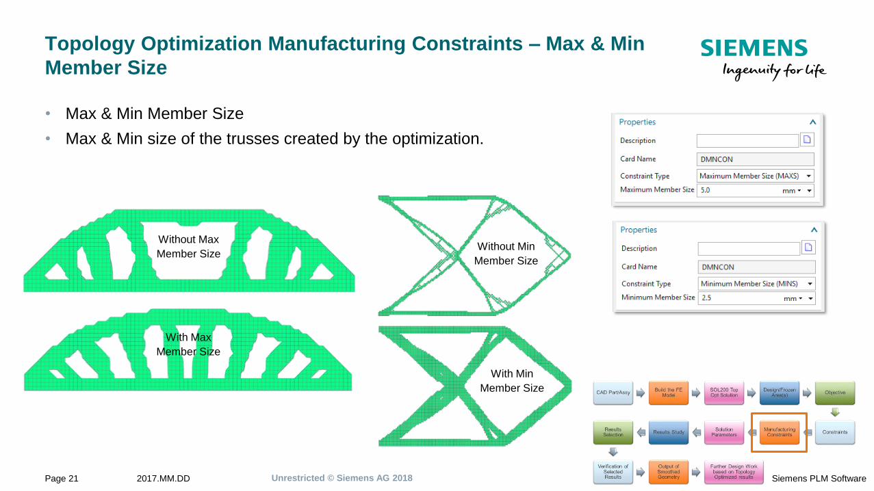
Topology Optimization Manufacturing Constraints – Max & Min
Member Size
• Max & Min Member Size
• Max & Min size of the trusses created by the optimization.
Without Max
Member Size
With Max
Member Size
Without Min
Member Size
With Min
Member Size
Unrestricted © Siemens AG 20182017.MM.DDPage 22 Siemens PLM Software
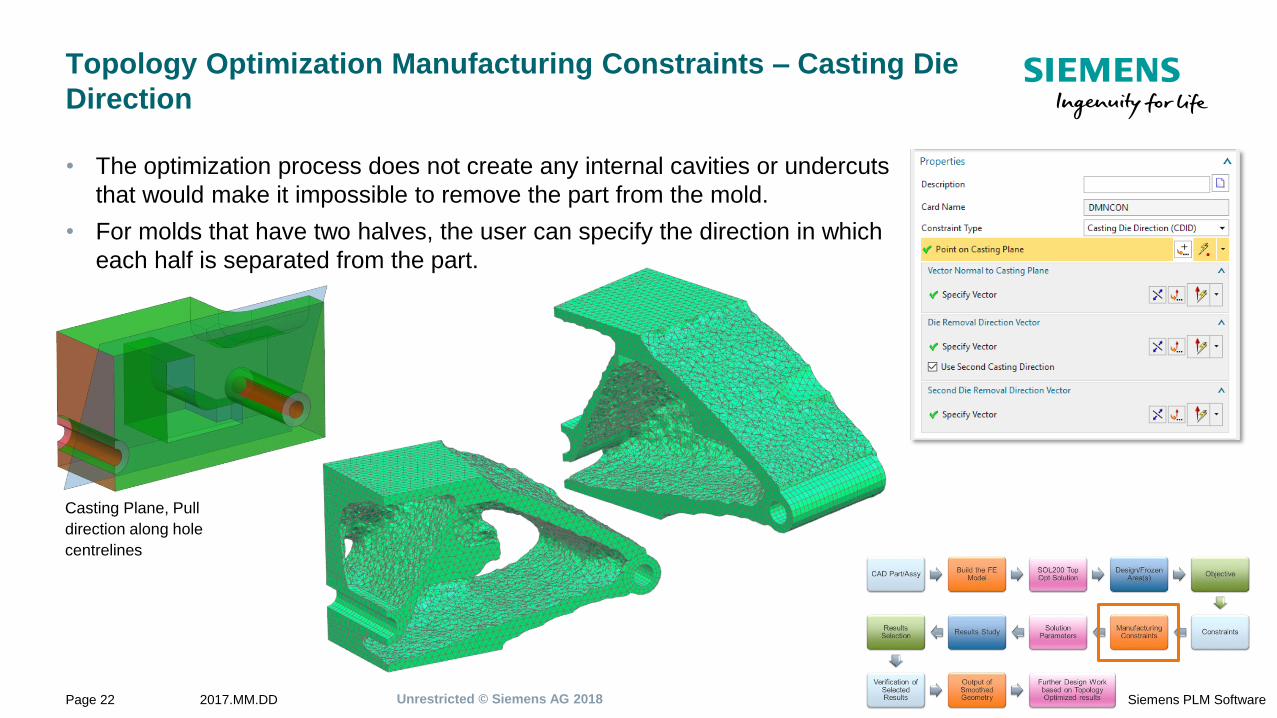
Topology Optimization Manufacturing Constraints – Casting Die
Direction
• The optimization process does not create any internal cavities or undercuts
that would make it impossible to remove the part from the mold.
• For molds that have two halves, the user can specify the direction in which
each half is separated from the part.
Casting Plane, Pull
direction along hole
centrelines
Unrestricted © Siemens AG 20182017.MM.DDPage 23 Siemens PLM Software
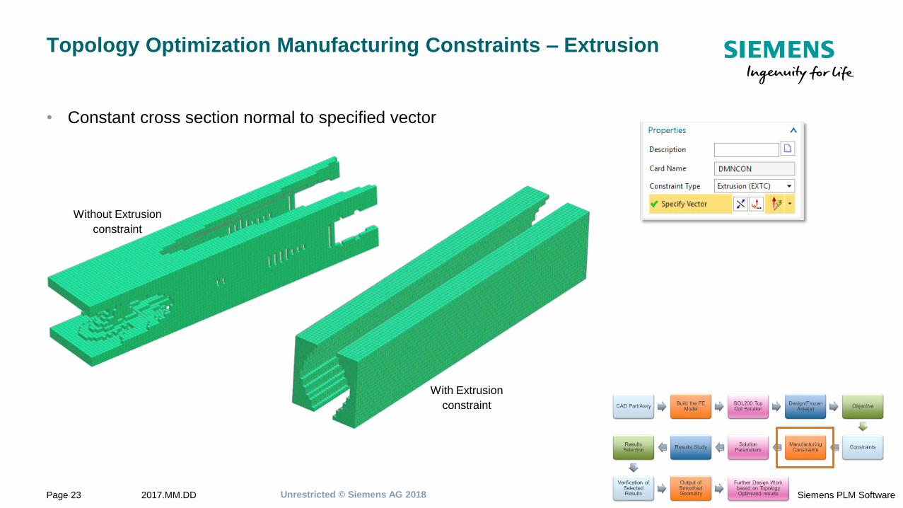
Topology Optimization Manufacturing Constraints – Extrusion
• Constant cross section normal to specified vector
Without Extrusion
constraint
With Extrusion
constraint
Unrestricted © Siemens AG 20182017.MM.DDPage 24 Siemens PLM Software
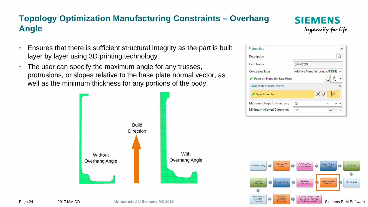
Topology Optimization Manufacturing Constraints – Overhang
Angle
• Ensures that there is sufficient structural integrity as the part is built
layer by layer using 3D printing technology.
• The user can specify the maximum angle for any trusses,
protrusions, or slopes relative to the base plate normal vector, as
well as the minimum thickness for any portions of the body.
With
Overhang Angle
Build
Direction
Without
Overhang Angle
Unrestricted © Siemens AG 20182017.MM.DDPage 25 Siemens PLM Software
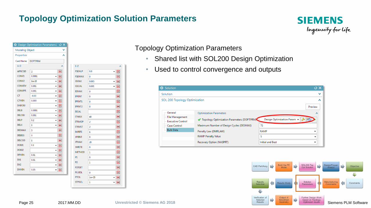
Topology Optimization Solution Parameters
Topology Optimization Parameters
• Shared list with SOL200 Design Optimization
• Used to control convergence and outputs
Unrestricted © Siemens AG 20182017.MM.DDPage 26 Siemens PLM Software
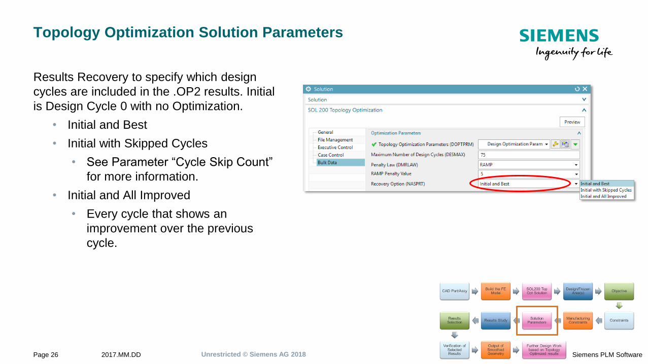
Topology Optimization Solution Parameters
Results Recovery to specify which design
cycles are included in the .OP2 results. Initial
is Design Cycle 0 with no Optimization.
• Initial and Best
• Initial with Skipped Cycles
• See Parameter “Cycle Skip Count”
for more information.
• Initial and All Improved
• Every cycle that shows an
improvement over the previous
cycle.
Unrestricted © Siemens AG 20182017.MM.DDPage 27 Siemens PLM Software
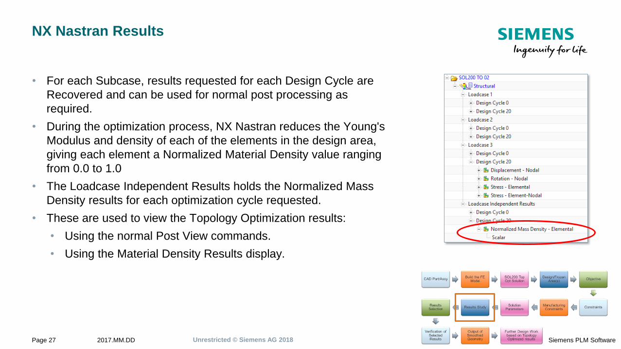
NX Nastran Results
• For each Subcase, results requested for each Design Cycle are
Recovered and can be used for normal post processing as
required.
• During the optimization process, NX Nastran reduces the Young's
Modulus and density of each of the elements in the design area,
giving each element a Normalized Material Density value ranging
from 0.0 to 1.0
• The Loadcase Independent Results holds the Normalized Mass
Density results for each optimization cycle requested.
• These are used to view the Topology Optimization results:
• Using the normal Post View commands.
• Using the Material Density Results display.
Unrestricted © Siemens AG 20182017.MM.DDPage 28 Siemens PLM Software
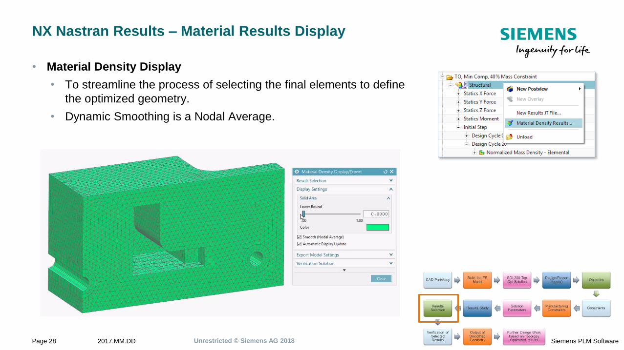
NX Nastran Results – Material Results Display
• Material Density Display
• To streamline the process of selecting the final elements to define
the optimized geometry.
• Dynamic Smoothing is a Nodal Average.
Unrestricted © Siemens AG 20182017.MM.DDPage 29 Siemens PLM Software
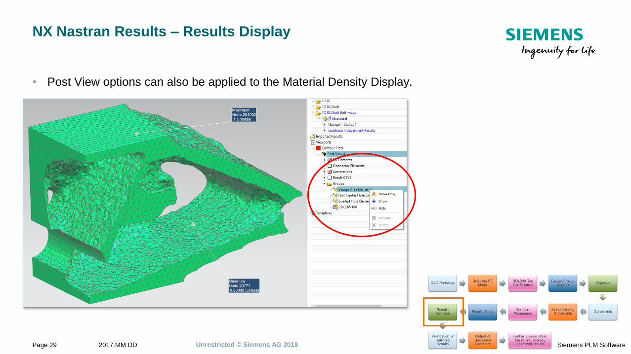
NX Nastran Results – Results Display
• Post View options can also be applied to the Material Density Display.
Unrestricted © Siemens AG 20182017.MM.DDPage 30 Siemens PLM Software
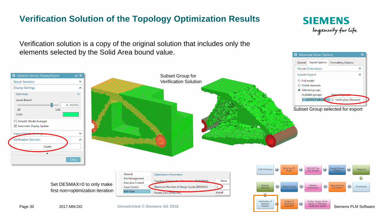
Verification Solution of the Topology Optimization Results
Verification solution is a copy of the original solution that includes only the
elements selected by the Solid Area bound value.
Subset Group for
Verification Solution
Set DESMAX=0 to only make
first non=optimization iteration
Subset Group selected for export
Unrestricted © Siemens AG 20182017.MM.DDPage 31 Siemens PLM Software
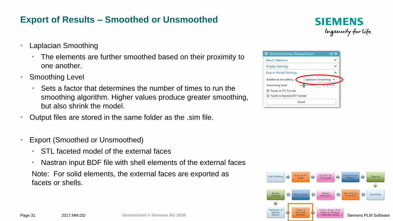
Export of Results – Smoothed or Unsmoothed
• Laplacian Smoothing
• The elements are further smoothed based on their proximity to
one another.
• Smoothing Level
• Sets a factor that determines the number of times to run the
smoothing algorithm. Higher values produce greater smoothing,
but also shrink the model.
• Output files are stored in the same folder as the .sim file.
• Export (Smoothed or Unsmoothed)
• STL faceted model of the external faces
• Nastran input BDF file with shell elements of the external faces
Note: For solid elements, the external faces are exported as
facets or shells.
Unrestricted © Siemens AG 20182017.MM.DDPage 32 Siemens PLM Software
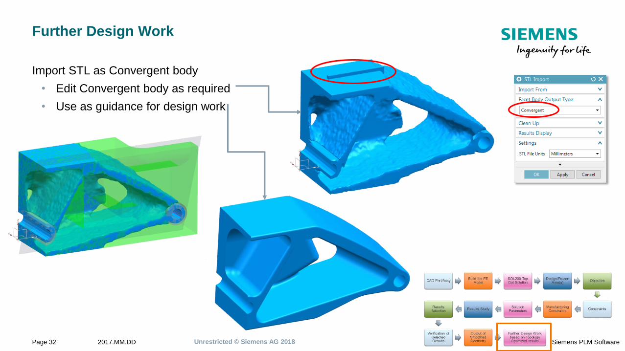
Further Design Work
Import STL as Convergent body
• Edit Convergent body as required
• Use as guidance for design work
Unrestricted © Siemens AG 20182017.MM.DDPage 33 Siemens PLM Software
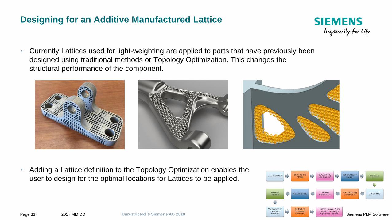
Designing for an Additive Manufactured Lattice
• Currently Lattices used for light-weighting are applied to parts that have previously been
designed using traditional methods or Topology Optimization. This changes the
structural performance of the component.
• Adding a Lattice definition to the Topology Optimization enables the
user to design for the optimal locations for Lattices to be applied.
Unrestricted © Siemens AG 20182017.MM.DDPage 34 Siemens PLM Software
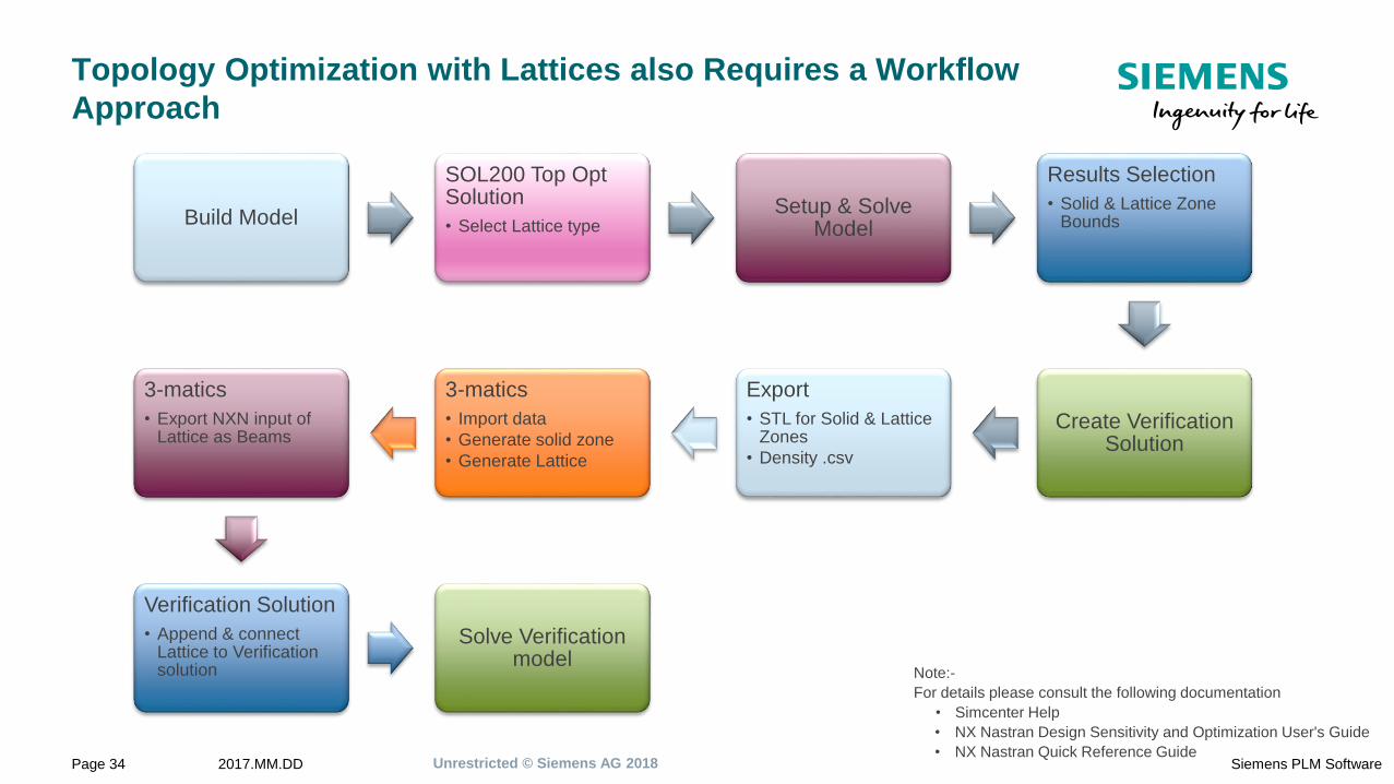
Topology Optimization with Lattices also Requires a Workflow
Approach
Build Model
SOL200 Top Opt Solution
• Select Lattice typeSetup & Solve
Model
Results Selection
• Solid & Lattice Zone Bounds
Create Verification Solution
Export
• STL for Solid & Lattice Zones
• Density .csv
3-matics
• Import data
• Generate solid zone
• Generate Lattice
3-matics
• Export NXN input of Lattice as Beams
Verification Solution
• Append & connect Lattice to Verification solution
Solve Verification model
Note:-
For details please consult the following documentation
• Simcenter Help
• NX Nastran Design Sensitivity and Optimization User's Guide
• NX Nastran Quick Reference Guide
Unrestricted © Siemens AG 20182017.MM.DDPage 35 Siemens PLM Software
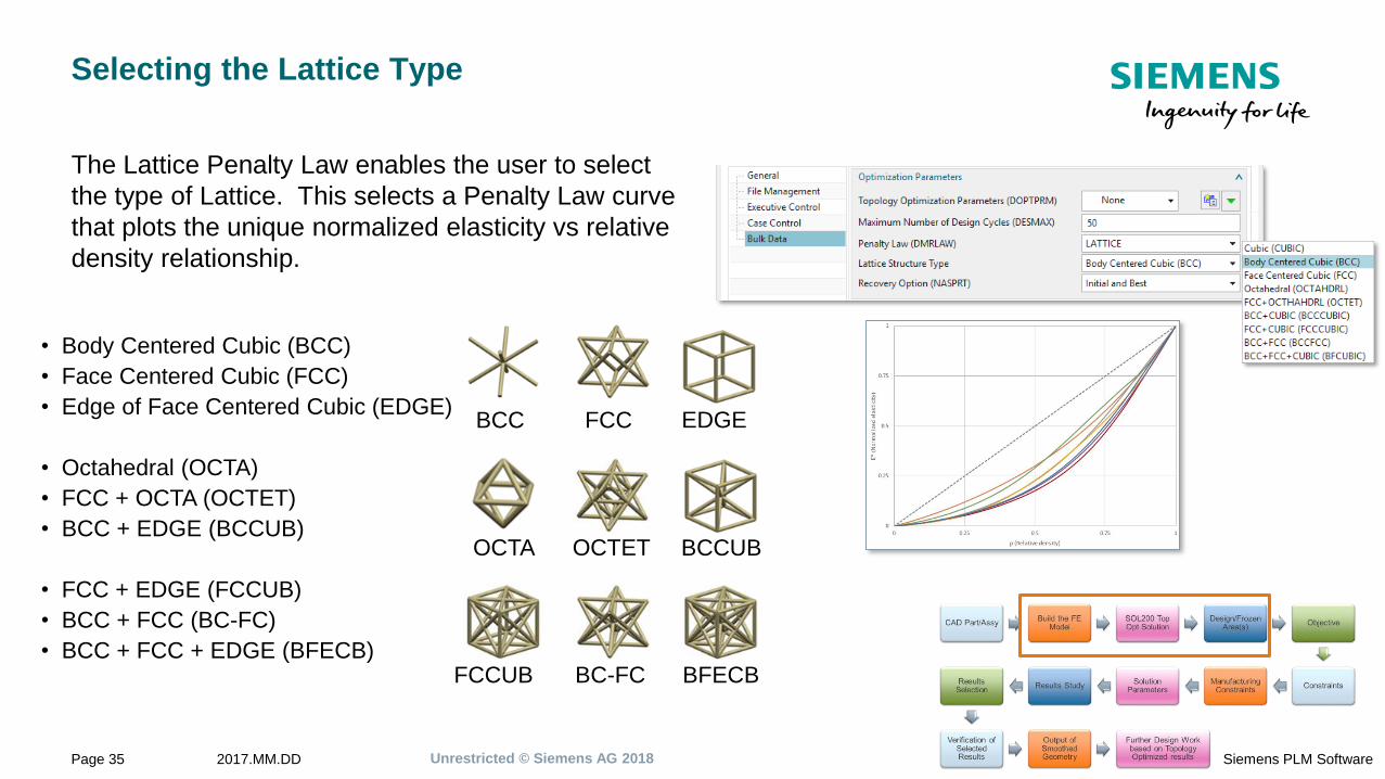
Selecting the Lattice Type
The Lattice Penalty Law enables the user to select
the type of Lattice. This selects a Penalty Law curve
that plots the unique normalized elasticity vs relative
density relationship.
• Body Centered Cubic (BCC)
• Face Centered Cubic (FCC)
• Edge of Face Centered Cubic (EDGE)
• Octahedral (OCTA)
• FCC + OCTA (OCTET)
• BCC + EDGE (BCCUB)
• FCC + EDGE (FCCUB)
• BCC + FCC (BC-FC)
• BCC + FCC + EDGE (BFECB)
BCC FCC EDGE
OCTA OCTET BCCUB
FCCUB BC-FC BFECB
Unrestricted © Siemens AG 20182017.MM.DDPage 36 Siemens PLM Software
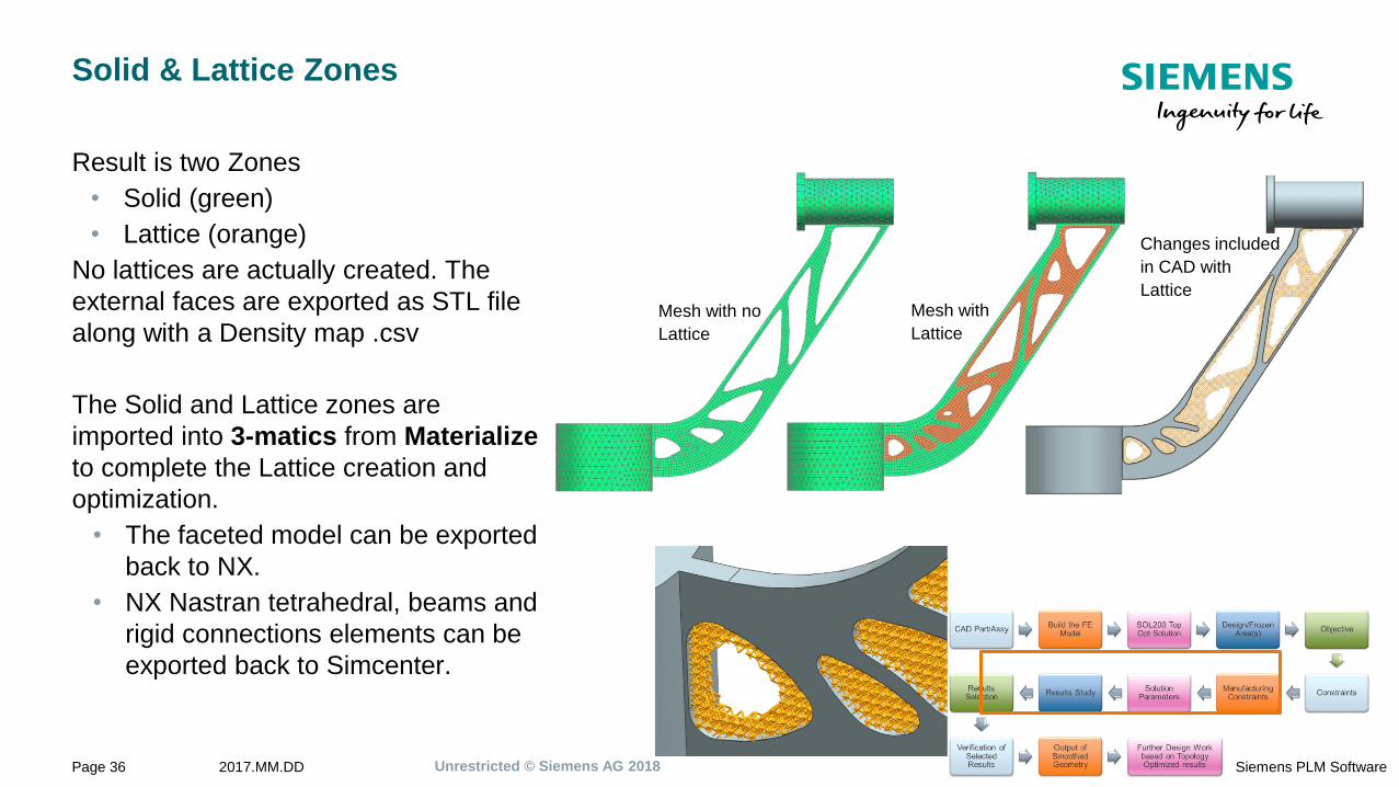
Solid & Lattice Zones
Result is two Zones
• Solid (green)
• Lattice (orange)
No lattices are actually created. The
external faces are exported as STL file
along with a Density map .csv
The Solid and Lattice zones are
imported into 3-matics from Materialize
to complete the Lattice creation and
optimization.
• The faceted model can be exported
back to NX.
• NX Nastran tetrahedral, beams and
rigid connections elements can be
exported back to Simcenter.
Mesh with no
Lattice
Mesh with
Lattice
Changes included
in CAD with
Lattice
Unrestricted © Siemens AG 20182017.MM.DDPage 37 Siemens PLM Software
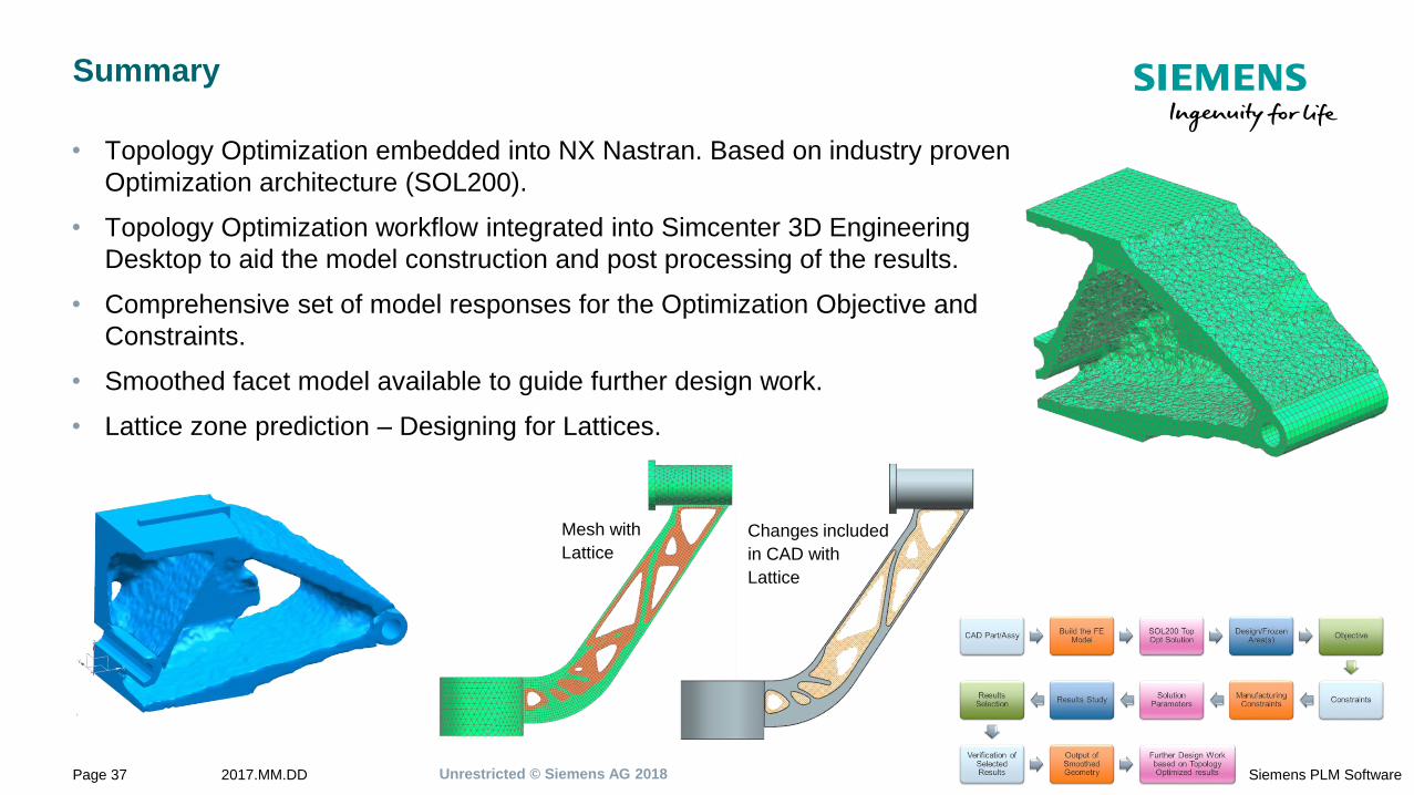
Summary
• Topology Optimization embedded into NX Nastran. Based on industry proven
Optimization architecture (SOL200).
• Topology Optimization workflow integrated into Simcenter 3D Engineering
Desktop to aid the model construction and post processing of the results.
• Comprehensive set of model responses for the Optimization Objective and
Constraints.
• Smoothed facet model available to guide further design work.
• Lattice zone prediction – Designing for Lattices.
Mesh with
Lattice
Changes included
in CAD with
Lattice
Guy WillsProduct Manager
Simcenter 3D Engineering Desktop
E-mail:
Realize innovation.