topology control of tactical wireless sensor … the nps institutional archive faculty and...
TRANSCRIPT

Calhoun: The NPS Institutional Archive
Faculty and Researcher Publications Faculty and Researcher Publications Collection
2016
Topology control of tactical wireless sensor
networks using energy efficient zone routing
Thulasiraman, Preetha
Chongqing University of Posts and Communications
Digital Communications and Networks (2016) 2, 1–14
http://hdl.handle.net/10945/50291

H O S T E D B Y
journal homepage: www.elsevier.com/locate/dcan
Available online at www.sciencedirect.com
Topology control of tactical wireless sensornetworks using energy efficient zone routing
Preetha Thulasiramann, Kevin A. White
Department of Electrical and Computer Engineering, Naval Postgraduate School, 833 Dyer Road,Spanagel Hall Rm 448C, Monterey, CA 93940, USA
Received 12 June 2015; received in revised form 3 December 2015; accepted 12 January 2016Available online 28 January 2016
KEYWORDSRouting;Energy efficiency;Wireless sensor net-works;Zones;Topology control
AbstractThe US Department of Defense (DoD) routinely uses wireless sensor networks (WSNs) for militarytactical communications. Sensor node die-out has a significant impact on the topology of a tacticalWSN. This is problematic for military applications where situational data is critical to tacticaldecision making. To increase the amount of time all sensor nodes remain active within the networkand to control the network topology tactically, energy efficient routing mechanisms must beemployed. In this paper, we aim to provide realistic insights on the practical advantages anddisadvantages of using established routing techniques for tactical WSNs. We investigate thefollowing established routing algorithms: direct routing, minimum transmission energy (MTE), LowEnergy Adaptive Cluster Head routing (LEACH), and zone clustering. Based on the node die outstatistics observed with these algorithms and the topological impact the node die outs have on thenetwork, we develop a novel, energy efficient zone clustering algorithm called EZone. Viaextensive simulations using MATLAB, we analyze the effectiveness of these algorithms on networkperformance for single and multiple gateway scenarios and show that the EZone algorithmtactically controls the topology of the network, thereby maintaining significant service areacoverage when compared to the other routing algorithms.& 2016 Chongqing University of Posts and Communications. Production and Hosting by Elsevier B.V.
This is an open access article under the CC BY-NC-ND license(http://creativecommons.org/licenses/by-nc-nd/4.0/).
1. Introduction
A Wireless Sensor Network (WSN) is a group of autonomoussensor nodes that are geographically distributed to gather dataand monitor events. WSNs are finding increased applicability tothe Department of Defense (DoD) in areas specific to surveil-lance and reconnaissance. A tactical WSN is used in a remotegeographic location in order to monitor deployed systems andtrigger alerts at a Command-and-Control (C&C) site when
http://dx.doi.org/10.1016/j.dcan.2016.01.0022352-8648/& 2016 Chongqing University of Posts and Communications. Production and Hosting by Elsevier B.V. This is an open access articleunder the CC BY-NC-ND license (http://creativecommons.org/licenses/by-nc-nd/4.0/).
nCorresponding author. Tel.: +1-(831) 656-3456fax: +1-(831) 656-2760
E-mail addresses: [email protected] (P. Thulasiraman),[email protected] (K.A. White).Peer review under responsibility of Chongqing University of Posts
and Telecommunications.
Digital Communications and Networks (2016) 2, 1–14

certain events occur. Each sensor node in the WSN must havethe ability to simultaneously serve as a sensing device and awireless communication device that can exchange informationwith nearby nodes [1]. The gateway serves as the destinationfor a node's packets is the bridge between the tactical WSN andthe backbone infrastructure which includes the C&C site.Because the gateway is a significant component of the WSNarchitecture, its location must be considered. We focus ourattention toward gateway locations on the periphery of thesensor field. For tactical WSNs, we assume that a location onthe periphery is more likely to be a safe zone compared towhere the sensor nodes are deployed. Our use of safe zonerefers to a location where the gateway is outside normalenvironmental and physical constraints to which sensor nodesmay be subjected.
In this paper, we investigate two types of tactical WSNs:(1) a single gateway scenario and (2) a multi-gatewayscenario. The majority of existing research on WSNs gen-erally includes the perspective of a single gateway [1–5].The few works that study multigateway sensor networksfocus on reliable routing, not taking into consideration theenergy efficiency requirements of the sensor nodes [6,7].Thus, it is important to extend WSN concepts to a multi-gateway framework and identify the resulting performanceimprovements by including an additional gateway.
1.1. Deployment challenges of tactical WSNs
A tactical WSN must operate reliably and increase sensornetwork coverage for as long as possible in the absence ofhuman contact. A key challenge in the deployment of tacticalWSNs is the limited battery power of each sensor node. This hasa significant impact on the service life of the network. Wedefine service life of a tactical WSN to be the amount of timethat nodes are able to transmit information to the gatewaywithout significant interruption. The service life of the networkis contingent upon the network topology. As nodes begin to dieout, the remaining live nodes may be disconnected from oneanother, undermining their ability to communicate with thegateway node. For example, if only 20% of the nodes in thenetwork remain alive (i.e., have enough residual energy to usefor transmitting, sensing and/or receiving), but they areconcentrated within transmission range one another, thencommunications can still take place for that area. This is thepreferred situation. However, with 80% of the nodes dead, thepossibility of live nodes residing in areas where they aredetached from one another is also possible. While this situationmay also occur in a commercially used WSN, the ramificationsof information not getting to the gateway may not be as severeas in a tactical WSN where important information from thebattlespace is being transmitted from the sensor nodes andbeing used for tactical decision making. Thus, the ability tocontrol the network topology using an effective routing algo-rithm is essential to ensuring that the network remains usablefor the longest amount of time. In this paper, topology controlrefers to the ability of the routing algorithm to ensure thatnodes with residual energy in one or more areas remainconnected to one another and/or the gateway for continueddata transfer.
1.2. Motivations and contributions
Energy efficient routing is not a new topic in WSN research.Extensive studies have been conducted in this area [1,2,8–14].Many of these works offer modifications to already wellestablished WSN routing algorithms. Both [12] and [13]provide algorithms for the modified Low Energy AdaptiveClustering Hierarchy (LEACH) algorithm [2]. In addition,[10,11,14] and [15] develop algorithms based on the idea ofclustering. Clustering is a common hierarchical routing pro-cedure implemented in WSNs. The idea is that energyconsumption is reduced by allowing only a select number ofnodes, known as Cluster Heads (CH), to aggregate data frommember nodes and transmit to the gateway. A disadvantagewith clustering is the CH election process. Depending on thetype of procedure used, CHs may be elected such that theyreside on the opposite end of the network [16]. This situationis common in LEACH where CHs are elected randomly basedon a probability model. This means that an elected CH maynot be physically close to node members. This then nullifiesany energy savings that clustering achieves. There have beenvarious modifications to LEACH in recent years, includingimprovements to LEACH security [17]. However, the funda-mental CH election procedure remains the same, exposingthe problem of CH election as mentioned above.
There has been some work that has been done on tacticalWSNs that serve as a foundation for our work [18,19]. While[18] and [19] provide architectural constraints for tacticalWSN deployment, the routing process and its impact onnetwork topology is not discussed. In [20], the authorsdevelop a cross layer load balancing/routing scheme fortactical WSNs. However, the authors do not provide an indepth analysis on the impact of tactical topology controlwhen using load balancing and routing algorithms.
In this paper we show traditional routing algorithms that areregularly used in commercial WSNs have a negative impact onthe service life of a tactical WSN because their design is notmeant to meet the requirements of tactical WSN applications.More specifically, we extend our work in [20] by showing thatestablished routing algorithms regularly seen in the literaturedo not effectively control the topology of the network. We aimto provide realistic insights on how an energy efficient routingalgorithm can increase service life by tactically controlling thenetwork topology. To the best of our knowledge, this is the firstwork to provide an extensive analysis of how different routingalgorithms impact the operational capability of a tactical WSN.
Our contributions in this paper can be summarized asfollows:
! Develop a novel energy efficient zone routing algorithmthat tactically controls the network topology. We call thisalgorithm EZone. We identify performance improvementsof EZone and compare it to the following establishedrouting techniques: (1) Direct Routing, (2) MinimumTransmission Energy (MTE), (3) Low Energy AdaptiveClustering Hierarchy (LEACH), and (4) Zone routing. Wealso identify performance improvements of adding anadditional gateway to these algorithms.
! As sensor-node battery levels are depleted and nodessubsequently die out, we show how EZone affects thetopology of live nodes and dead nodes in the sensor field
P. Thulasiraman, K.A. White2
and how this affects the continuous service coveragethroughout the sensor field. We compare EZone servicelife with the network service life obtained using each ofthe four routing algorithms mentioned above and showEZone's ability to tactically provide continuous service.
The remainder of this paper is organized as follows. InSection 2, we discuss the models implemented at each layerof the tactical WSN protocol stack. In Section 3, we discussthe EZone algorithm and its implementation. Ezone iscompared with four traditional routing algorithms that arealso described. We provide our simulations and analysis ofthe results in Section 4. We conclude the paper in Section 5.
2. Tactical WSN protocol stackimplementation
We implemented the following models into each layer of theprotocol stack.
Physical layer: All nodes in our simulations begin with astarting energy level of 0.5 Joules (J). This is a valuecommonly used in the literature because it provides smallenough energy to quickly see the effects of the varyingalgorithms involved yet it provides enough energy todemonstrate node life longevity by making algorithmicimprovements.
The physical model relates to the amount of energy asensor node consumes during transmit and receive opera-tions. Several power energy consumption models exist inthe literature [21–24]. Each model presents a different wayof calculating total energy consumption for different sensornodes. We chose to utilize a first order power amplifier andsensor model for simplicity and because it is more preva-lently used in the literature [2,25,26]. This model assigns anenergy cost-per-bit to collect, transmit and receive infor-mation. It considers direct path and multi-path wirelesssignal propagation theory to identify the amount of infor-mation required to transmit one bit of information over acertain distance between nodes while guaranteeing ade-quate signal-to-noise (SNR) ratio at the receiving node. Weutilize the first order radio energy model to relate theenergy expended to send and receive an L-bit message overa distance d when considering direct path and multi-pathpropagation [1,2,16,27].
The energy expended in the transmit electronics for freespace (direct path) propagation, ETx" fs, is described by
ETx" fsðL;dÞ ¼ ETx"elecðLÞþETx"ampðL; dÞ ¼ EelecLþεfsLd2 ð1Þ
and for multipath propagation by
ETx"mpðL; dÞ ¼ ETx"elecðLÞþETx"ampðL; dÞ ¼ EelecLþεmpLd4
ð2Þ
where Eelec corresponds to the energy per bit required intransmit and receive electronics to process the information,ETx"amp is the electrical energy required to transmit anL-bit message over a distance d, and εfs and εmp areconstants corresponding to the energy per bit required inthe transmit amplifier to transmit an L-bit message withadequate SNR over a distance d2 and d4 for free space andmulti-path propagation modes, respectively.
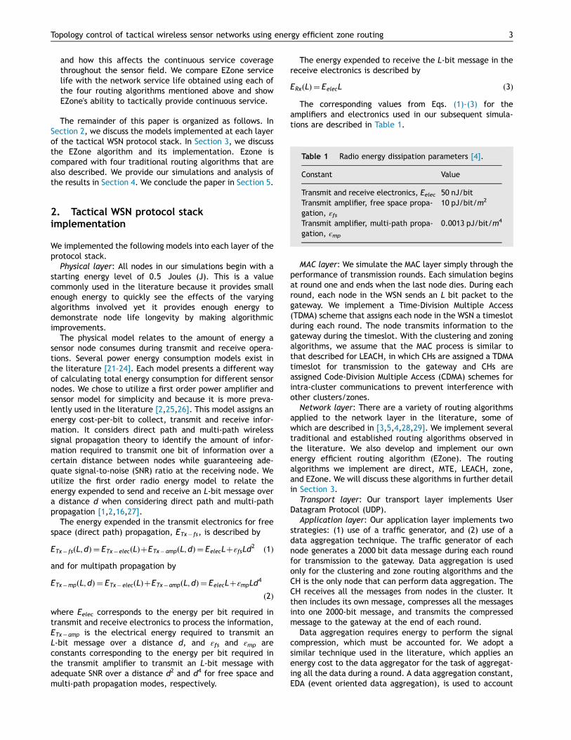
The energy expended to receive the L-bit message in thereceive electronics is described by
ERxðLÞ ¼ EelecL ð3Þ
The corresponding values from Eqs. (1)–(3) for theamplifiers and electronics used in our subsequent simula-tions are described in Table 1.
MAC layer: We simulate the MAC layer simply through theperformance of transmission rounds. Each simulation beginsat round one and ends when the last node dies. During eachround, each node in the WSN sends an L bit packet to thegateway. We implement a Time-Division Multiple Access(TDMA) scheme that assigns each node in the WSN a timeslotduring each round. The node transmits information to thegateway during the timeslot. With the clustering and zoningalgorithms, we assume that the MAC process is similar tothat described for LEACH, in which CHs are assigned a TDMAtimeslot for transmission to the gateway and CHs areassigned Code-Division Multiple Access (CDMA) schemes forintra-cluster communications to prevent interference withother clusters/zones.
Network layer: There are a variety of routing algorithmsapplied to the network layer in the literature, some ofwhich are described in [3,5,4,28,29]. We implement severaltraditional and established routing algorithms observed inthe literature. We also develop and implement our ownenergy efficient routing algorithm (EZone). The routingalgorithms we implement are direct, MTE, LEACH, zone,and EZone. We will discuss these algorithms in further detailin Section 3.
Transport layer: Our transport layer implements UserDatagram Protocol (UDP).
Application layer: Our application layer implements twostrategies: (1) use of a traffic generator, and (2) use of adata aggregation technique. The traffic generator of eachnode generates a 2000 bit data message during each roundfor transmission to the gateway. Data aggregation is usedonly for the clustering and zone routing algorithms and theCH is the only node that can perform data aggregation. TheCH receives all the messages from nodes in the cluster. Itthen includes its own message, compresses all the messagesinto one 2000-bit message, and transmits the compressedmessage to the gateway at the end of each round.
Data aggregation requires energy to perform the signalcompression, which must be accounted for. We adopt asimilar technique used in the literature, which applies anenergy cost to the data aggregator for the task of aggregat-ing all the data during a round. A data aggregation constant,EDA (event oriented data aggregation), is used to account
Table 1 Radio energy dissipation parameters [4].
Constant Value
Transmit and receive electronics, Eelec 50 nJ/bitTransmit amplifier, free space propa-gation, εfs
10 pJ/bit/m2
Transmit amplifier, multi-path propa-gation, ϵmp
0.0013 pJ/bit/m4
3Topology control of tactical wireless sensor networks using energy efficient zone routing

for the energy to compress messages into one final L=2000bit message. The data aggregation constant used in ourscenarios is consistent with the literature (EDA=5 nJ/bit)and results in an aggregation cost of EDA' L [1,2,27,30,31].
3. Routing algorithms for tactical WSNs:traditional vs EZone
In this section, we describe the five routing algorithms thatwere simulated: direct, MTE, LEACH, Zone, and EZone.
3.1. Traditional routing algorithms: direct, MTE,LEACH and zone
Direct transmission to the gateway involves each node sending apacket to the gateway directly without using any other nodesalong the way. During each round, the Euclidean distance iscalculated between the node and the gateway. The distancealong with the transmit amplifier parameters given in Table 1 isused to determine the propagation mechanism [16]. The node'senergy is decremented in proportion to the required energy forpacket transmission to the gateway.
In MTE routing we minimize the propagation distance tothe gateway in order to produce a route that minimizes theoverall sensor energy depletion rate. We utilize propagationdistance as our link cost parameter to input into the MTEalgorithm. We use Dijkstra's algorithm to generate our MTEroutes. In MTE routing, the node closest to the gateway isalways chosen to be included in the route. This node isknown as the hot node. Since the hot node is the relay pointbetween the gateway and all traffic from other nodes, it isoverwhelmed with traffic during each round and diesquickly. Another hot node is then immediately chosen. Thishot node concept in MTE routing causes nodes that areclosest to the gateway to die out first.
The LEACH algorithm is a well-known clustering algorithmdeveloped specifically for WSNs. LEACH routing elects oneor more CHs and nodes associate with the nearest CH. Therole of CH is rotated among the nodes in the following way:each node picks a random number between zero and one.Each node also computes a threshold number (Tn), which isa number between zero and one and is proportional to thecurrent round. The probability for any node to serve as a CHis denoted as p. If a node has been a CH in the last 1
p rounds,it is excluded from being a CH during the round. Otherwise,if the temporary random number is less than Tn, the node iselected as a CH during the round. The desired probabilityfor a node to be chosen as a CH is an input to the algorithmand must be specified. The original authors of LEACHperformed analysis to determine the optimum value for pto be 0.05 [1]. Each node transmits its data message to itsCH. Each CH collects all the messages of its nodes andretransmits them collectively to the gateway. This processrepeats during subsequent rounds until all nodes have died.
Zone clustering appears less frequently in the literatureas compared to LEACH. However, for a tactical network, itmay be a preferred routing algorithm because the user canspecify how zones are characterized for the network. Thegeneral methods used for the zone routing algorithm arebased on techniques described in [8]. In [8], the authorsutilize a sensor field comprised of homogeneous zones.
Partitioning the network in zones essentially creates severalsmaller WSNs that all utilize the same gateway. A sensor ineach zone has a probability p of becoming a CH during eachround. The probability p is determined to be relative to thenumber of nodes in the zone: p¼ 1
ðnumber of nodes in zoneÞ. Thezone clustering algorithm divides the sensor field into zequal zones. Equal zones span along the Cartesian x-axis tocreate z vertical rectangular zones. We use five zones in oursimulations. Five zones were chosen to provide a compar-ison with the LEACH algorithm. Recall that in the LEACHalgorithm, the probability of any node being chosen as a CHis p=0.05. Thus, in a 100 node network, we would have fiveCHs. To ensure that there are five CHs for our zoneclustering algorithm, we must have five zones and eachzone is only allowed to have one CH.
During each round, the set of live nodes for each zone isidentified, and the CH is chosen based on a random assign-ment from this set. Each node in the zone then transmits itsL-bit packet to the zone's CH and its energy is decrementedaccording to our radio energy model. The CH for the zonethen aggregates all the messages from the nodes in the zoneand transmits the aggregated message to the gateway.
For all four routing algorithms discussed in this section,the multigateway scenarios operate the same way asdescribed, except the gateway that is closest to each nodein terms of Euclidean distance is chosen to receive data.
3.2. EZone: zone clustering with energy efficientcluster head selection
The zone clustering case described in Section 3.1 choosesthe CH for each zone randomly. A clustering algorithm thatpartitions nodes into specific zones is an energy savingtechnique when compared to the LEACH algorithm becausethere is a lower maximum distance that any node musttransmit to reach its CH. Zone routing guarantees a nearbyCH in the zone as compared to that of LEACH. In LEACH thenearest CH may be on the other side of the network sincethe criteria for a node to be elected as a CH may have onlybeen met randomly on the other side of the field [16].
There are significant differences in energy distribution ofthe nodes in the network. The differences in energy levelsacross the WSN cause some nodes to die out earlier andsome nodes to die out later. Therefore, in the EZonealgorithm, we modify the CH election criteria in thefollowing way: in any given round, if the highest energynode is chosen to be the CH, individual node energydepletion rates are decreased allowing battery levels inany zone to deplete at a uniform rate.
To accomplish this strategy, the zone routing algorithm isrevised. Instead of randomly choosing the CH from the livenodes in the zone, we choose the CH that has the maximumenergy level in the zone. Based on this election criterion,nodes that are in a more preferred location (a location thatdecreases energy depletion rate such as locations closer tothe gateway) are chosen to be the CH for the zone morethan those in a less preferred location (a location fartheraway from the gateway).
The EZone algorithm is executed in three phases: (1) net-work setup; (2) CH election for each zone; and (3) packettransmission from CH to gateway. The network setup phase
P. Thulasiraman, K.A. White4

creates the WSN and partitions the network into therequired number of zones. The number of zones is basedon user requirements and application scenario. We use5 zones to facilitate comparison with the zone routingalgorithm using random CH election given in [8]. Partition-ing the network into zones effectively creates severalsmaller WSNs that all utilize the same gateway. The zoneassigned to any node is based on the node's x-coordinate inthe network field. Once all nodes are assigned to a zone, webegin the simulation at round one. In each round, the set oflive nodes for each zone is identified and the CH is electedbased on highest node energy.
Electing the highest energy node to be the CH during eachround in each zone requires additional processing by thegateway to perform CH election. In order for the gateway tomake an effective CH choice for each zone, it must beaware of all the alive nodes in each zone and the residualenergy (remaining energy) of each alive node. Each node inthe zone maintains a power meter that is used to maintainnode residual power. Each alive node in each zone decre-ments its power meter each time it transmits a packet tothe clusterhead of that zone. The decrement is based on theradio energy model given in Eqs. (1) and (2). All alive nodescommunicate with the gateway during the start of eachround. During round 1 only, the gateway chooses the CHrandomly, similar to [8]. The reason the CH is chosenrandomly for round 1 is because it is assumed that at thestart of the algorithm all nodes have equal energy and thusany node can be the CH. The CH of round 1 transmits anaggregated packet to the gateway. The aggregated packetincludes the residual node energies for each alive node inthe zone (including the current CH) in the packet header.The gateway uses the residual power values to choose theCH for each zone for the next simulation round. The nodewith the highest residual energy is chosen by the gateway tobe the CH for the subsequent round. The CH choice is thenbroadcast back to each zone. Once a CH is elected by thegateway, the CH maintains its power meter by (1) decre-menting the energy required to aggregate and send thepacket for that round to the gateway based on the radioenergy model and (2) decrementing the energy cost for theCH to receive packets from nodes in its zone. The decre-ment is calculated based on Eq. (3).
This CH selection based on highest node residual energy isa minor adjustment from the traditional zone routingalgorithm but it has a significant effect on the service lifeand network topology of a tactical WSN, as will be shownin Section 4.
4. Simulations and result analysis
In our simulations, sensors and gateways are all placed on aCartesian grid with axes x and y. Our simulations andanalysis involve a grid of 100 sensors such that each sensor'sx and y coordinate is modeled as a uniformly distributedrandom variable between 0 and 50 meters (m). The singlegateway scenario employs the gateway at (x, y)=(25 m,"100 m). In the multigateway scenario an additional gate-way is placed at the position (25 m, 150 m). In the subse-quent figures, gateways are displayed as solid green nodesand live nodes are represented by a blue outline circle. We
show the perimeter and zone fields as solid red lines. Allnodes have a starting energy of 0.5 J, except the gateway(s) which is assumed to have unlimited energy (they are notenergy constrained). The traffic routed in the network isgenerated using a Constant Bit Rate (CBR). The size of eachmessage (L) is 2000 bits.
All our simulations assume that each node is withinwireless transmission range of the gateway which alsomeans that each node is within communication range ofany other node in the WSN. We make this assumption inorder to simplify the simulation scenario. This simplificationmakes it easier to analyze node-die out statistics andnetwork topology characteristics for each routing algorithmexecuted. In our future work, we will loosen this assump-tion. All our simulations were executed in MATLAB.
4.1. Topology control analysis of routingalgorithms: traditional vs EZone
In every round we generate several plots to characterizeenergy consumption and the distribution of live and deadnodes in the network. We produce three plots during eachround. The first plot is a bar plot that provides the energy ofeach node from 1 to 100 where node 1 is the closest node tox=0 (the y-axis) and node 100 is on the other side of thesensor field closest to the line x=50 m. The second plot is athree-dimensional energy stem plot where each stem islocated in the position of the node in the field, and theheight of the stem represents the amount of residualbattery energy available. The energy stem plot is green,and the elevation (energy level) decreases during eachround, corresponding to energy consumption. When thestem reaches zero energy (the floor), the green bubblechanges to red to indicate the node has died. The final plotis an overview of the sensor field topology including thegateway during a particular round. We refer to the first plotas the energy bar plot, the second plot as the energy stemplot and the third plot as the node distribution plot. Thenode distribution plot shows live nodes as a circle with ablue outline and dead nodes as solid red bubbles. The nodedistribution plot also contains the round from which allthree plots are drawn. The energy bar and stem plots arestacked on top of each other on the left hand side of thefigures, and the node distribution plot is on the right side ofthe figures. For each simulation, this is plotted four timescorresponding to the round the first node dies and the roundthat 10%, 50%, and 80% of nodes have died. To constrain thelength of this paper, we provide the plots for 80% of nodesdead to illustrate the operational mechanism of the directand MTE routing algorithms. We provide the plots for 10%and 50% of nodes dead to illustrate LEACH and generic zonerouting. We provide plots for 10%, 50%, and 80% of nodesdead for the EZone routing algorithm. Due to space, theseplots are graphically shown for the single gateway scenarioonly (in Section 4.2 we provide further discussion on themultigateway scenarios by providing ensemble graphs thatshow the performance of each routing algorithm in multi-gateway scenarios). The results depicted in Figs. 1–9 aresimulations of one specific topological configuration.
Direct transmission: The plot for 80% of nodes dead isshown in Fig. 1. The energy stem plot demonstrates that
5Topology control of tactical wireless sensor networks using energy efficient zone routing

nodes closest to the gateway remain in service longer thannodes farther from the gateway because our physical layerdepletes energy proportional to distance.
MTE with Dijkstra routing: The plot for 80% of nodes deadis shown in Fig. 2. The energy stem plot and node distribu-tion plots demonstrate that nodes closest to the gatewaydie out first and then fan out as subsequent live nodesclosest to the gateway become the hot nodes. As expected,this quickly eliminates service coverage in those areas.Nodes that are farthest away from the gateway are notused by their peers as frequently for routing, thus theirenergy is preserved. This creates a large energy varianceand the quickest die out for all results collected in thispaper (variance results produced by each routing algorithmare further examined in the next section).
LEACH: The 10% and 50% of nodes dead are plotted inFigs. 3 and 4, respectively. The CHs are indicated by a blueasterisk that fills the nodes. Our display of CHs involves onecaveat for LEACH and zone routing algorithms. In somecases, the CH asterisk indicator is plotted over with a solidred circle because its energy was fully depleted in its lastround as the CH. Our plots are drawn at the end of eachround; thus, if a node is dead and it was the CH during theround, it is depicted as a dead node. The energy stem plotand node distribution plots in both figures demonstrate thatnodes die out starting in the middle of the network andprogress out. From this outward progression, nodes toward
the top of the network die out more quickly than nodes atthe bottom of the sensor field because nodes at the top usemore energy to transmit a cluster's payload to the gatewayduring the random times they are selected as the CH. Nodesat the center of the field start to die out first as a result ofLEACH's mechanism for determining CHs and cluster assign-ments at each round. Thus, this shows that LEACH ineffi-ciently partitions the sensor field with CHs, without regardto any spatial arrangement.
Zone routing: The plots for 10% and 50% of nodes deadare shown in Figs. 5 and 6, respectively. The energy stemplot and node distribution plots demonstrate much moreuniform energy depletion as compared to all the otheralgorithms tested thus far. Since any node can be randomlyselected to be a CH more than any other node in thenetwork, this creates a random mode for nodes to die out.Zones in the node distribution plots die out consistently withno one zone dying out earlier than another zone. We foundthat when the zone algorithm is run, the first node dies atround 1649, providing the longest service life of 100% ofnodes alive of all algorithms tested thus far. This will befurther discussed in the next section.
EZone: We provide plots for the EZone routing algorithmwhen 10%, 50% and 80% of the nodes die. These plots areshown in Figs. 7–9. The energy stem plot and node distribu-tion plots demonstrate that zones die out from the outerzones in the sensor network, progressing toward the center.
Fig. 1 Illustration of a single gateway tactical WSN for direct routing. The network topology when 80% of the nodes are dead is onthe right of each subplot, the energy stem plot is shown in the lower left and the energy bar plot is on the upper left of the subplots.
P. Thulasiraman, K.A. White6
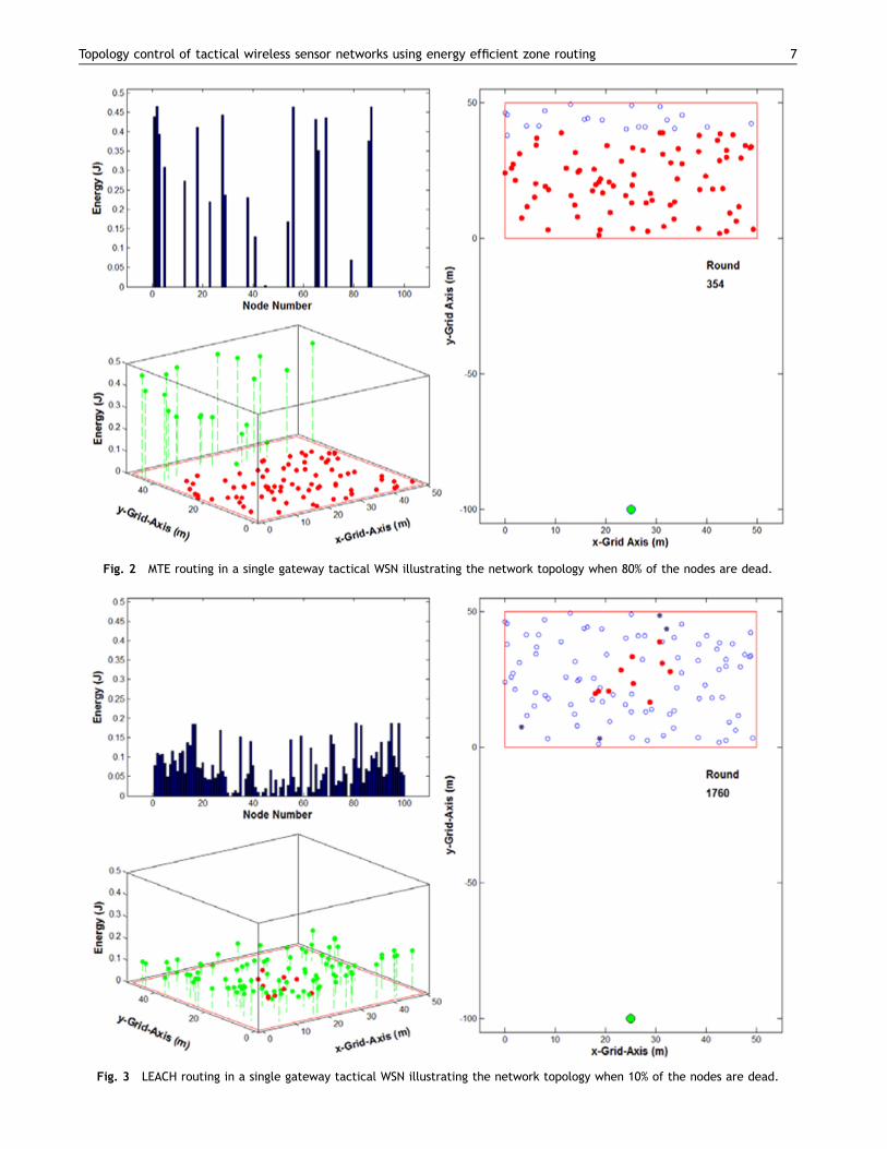
Fig. 2 MTE routing in a single gateway tactical WSN illustrating the network topology when 80% of the nodes are dead.
Fig. 3 LEACH routing in a single gateway tactical WSN illustrating the network topology when 10% of the nodes are dead.
7Topology control of tactical wireless sensor networks using energy efficient zone routing

Fig. 4 LEACH routing in a single gateway tactical WSN illustrating the network topology when 50% of the nodes are dead.
Fig. 5 Zone routing in a single gateway tactical WSN illustrating the network topology when 10% of the nodes are dead.
P. Thulasiraman, K.A. White8

Fig. 6 Zone routing in a single gateway tactical WSN illustrating the network topology when 50% of the nodes are dead.
Fig. 7 EZone routing in a single gateway tactical WSN illustrating the network topology when 10% of the nodes are dead.
9Topology control of tactical wireless sensor networks using energy efficient zone routing
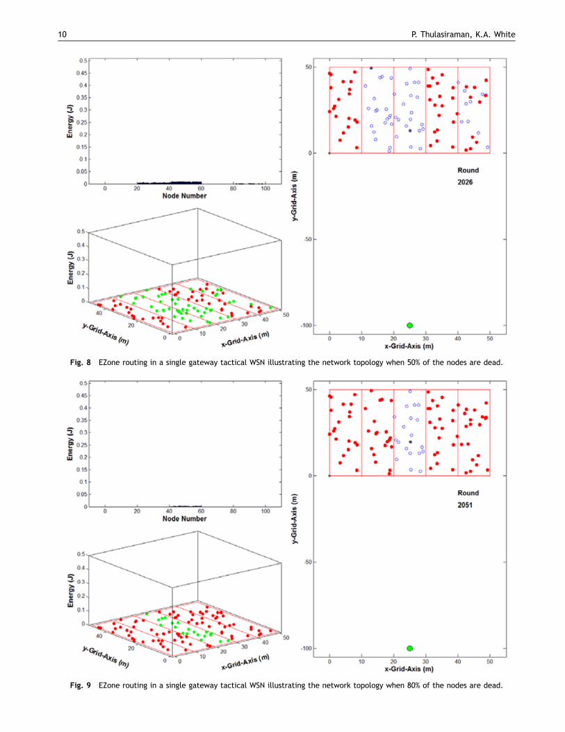
Fig. 8 EZone routing in a single gateway tactical WSN illustrating the network topology when 50% of the nodes are dead.
Fig. 9 EZone routing in a single gateway tactical WSN illustrating the network topology when 80% of the nodes are dead.
P. Thulasiraman, K.A. White10

By restricting CH election criteria to choose the highestenergy node in a zone, the energy level of all nodes in acommon zone are uniformly preserved throughout thesimulation and thus nodes die out evenly.
Notice in Fig. 9, the middle zone is 100% still in serviceeven when all nodes in the other four zones are dead. This isa valuable consequence of the EZone algorithm. Eventhough 80% of the nodes are dead, the fact that one zoneis still fully operational is significant for tactical operations;data sensed and transmitted within that middle zone will besent to the gateway. Nodes within that middle zone haveneighboring nodes that are still alive through which totransmit data. This ensures that the network remainsvaluable from a tactical perspective.
4.2. Comparisons of the algorithms based onenergy consumption
We plotted the total tactical WSN system energy levelduring each transmission round (Fig. 10), the energy var-iance that resulted from the distribution of individual nodebattery levels (Fig. 11) and the number of live nodes duringeach round (Fig. 12). We visually observed how nodesgeographically die out throughout the simulation. Theresults shown in Figs. 10–12 were obtained when 5000different network topologies were simulated. Each routingalgorithm was executed on each of the 5000 topologies andthe average results are depicted in the figures. In eachlegend of Figs. 10–12, S after an algorithm name refersto the single gateway scenario, and M refers to the multi-gateway scenario. The variance is given by the followingequation.
Var Eð Þ ¼1n
Xn
i ¼ 1
ðei"μÞ2 ð4Þ
where E is the random variable for energy, n represents thenumber of live nodes in the round, ei is the energy of the ithlive node in the round and μ is the mean energy forthe round.
The clustering algorithms dramatically outperformed theMTE and direct routing algorithms. This is a result of rotatingand distributing the high energy role of nodes that performlong-range transmission and data aggregation. The single andmultigateway clustering algorithms generally displayed simi-lar energy depletion rates that are illustrated in the linearregions of Fig. 10. The clustering algorithms decrease theenergy variance of the tactical WSN, and our energy efficientzone routing algorithm, EZone, provided an indistinguishableflat variance plot compared to the other algorithms, asshown in Fig. 11. In Fig. 12 it can be seen that EZoneincreased the time when all nodes are alive, with the singlegateway EZone simulation outperforming all the otheralgorithms.
Our EZone algorithm outperformed all other algorithmsfrom a topology perspective during node die out as well.While the algorithms created a pattern for die out, ourenergy efficient algorithm kept all nodes in one area/zonealive for the longest time possible. Node dies out of theother routing algorithms occurred in an unfavorable fashion.For example, in the direct case, live nodes farther from thegateway died first since their energy is depleted propor-tional to their distance from the gateway. As a result, areasfarthest from the gateway lost service first, while areasclosest to the gateway remained in service longest. In MTErouting the nodes closest to the gateway died first. TheLEACH algorithm inefficiently creates clusters that causethe network to die out starting in the center of the sensorfield and progressing radially outward. As a result of this dieout mechanism, we lose coverage in the middle of thesensor field first. These dying out mechanisms warrant the
Fig. 10 Total tactical WSN system energy versus transmission round for direct, MTE, LEACH, zone and EZone routing algorithms insingle gateway and multigateway scenarios.
11Topology control of tactical wireless sensor networks using energy efficient zone routing
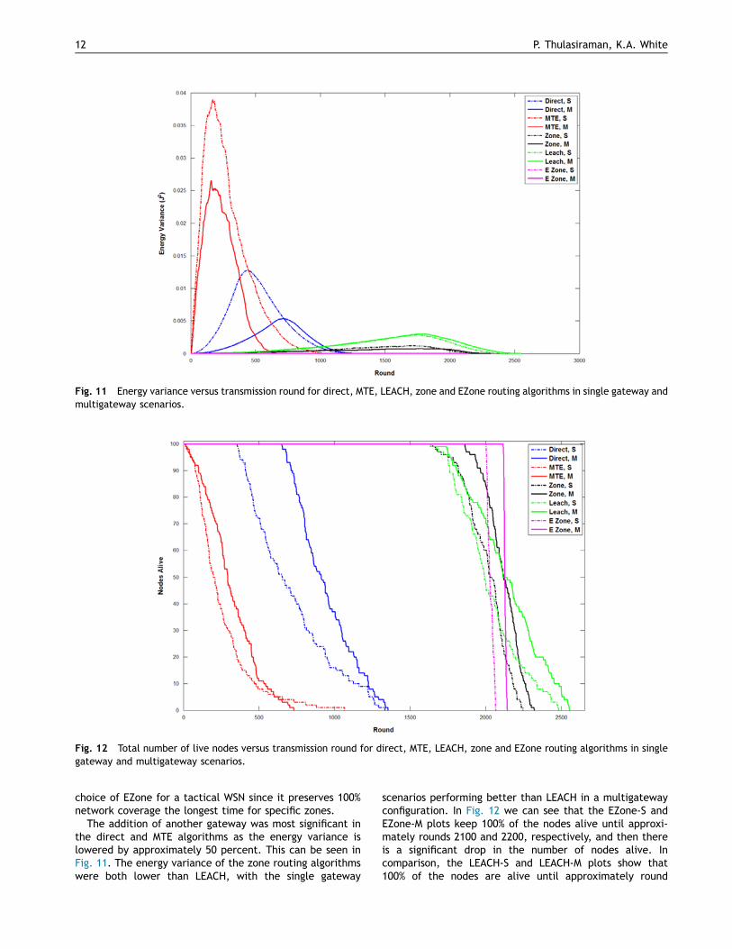
choice of EZone for a tactical WSN since it preserves 100%network coverage the longest time for specific zones.
The addition of another gateway was most significant inthe direct and MTE algorithms as the energy variance islowered by approximately 50 percent. This can be seen inFig. 11. The energy variance of the zone routing algorithmswere both lower than LEACH, with the single gateway
scenarios performing better than LEACH in a multigatewayconfiguration. In Fig. 12 we can see that the EZone-S andEZone-M plots keep 100% of the nodes alive until approxi-mately rounds 2100 and 2200, respectively, and then thereis a significant drop in the number of nodes alive. Incomparison, the LEACH-S and LEACH-M plots show that100% of the nodes are alive until approximately round
Fig. 11 Energy variance versus transmission round for direct, MTE, LEACH, zone and EZone routing algorithms in single gateway andmultigateway scenarios.
Fig. 12 Total number of live nodes versus transmission round for direct, MTE, LEACH, zone and EZone routing algorithms in singlegateway and multigateway scenarios.
P. Thulasiraman, K.A. White12
1800 but there is a more gradual drop off in the number ofnodes alive. This supports our assertion that EZone offersthe most time with all nodes alive whereas LEACH offers themost time with at least one node alive.
This is an important distinction, particularly when dealingwith tactical operations. While having at least one nodealive may be useful in commercial WSNs, it is not practicalfor WSNs deployed for tactical operations. With one nodealive, there is very little that can be done, unless the nodeis very close to the gateway. Even if more than one node isalive, the possibility of having nodes alive in different areasof the network that are not connected is also not helpful intactical operations. Thus, EZone's ability to keep all nodesalive for a longer period of time than LEACH combined withits ability to keep all nodes within one zone alive (see Fig. 9)makes it more applicable for use in tactical networks.
5. Conclusion
Tactical WSNs are used by the military to obtain informationabout ground situational awareness. This information facil-itates tactical decision making. In order to increase servicelife in various areas of a tactical WSN, we need to controlthe network topology such that nodes with residual energyare used and maintained for continuing communication. Wedevelop an energy efficient zone routing algorithm, calledEZone, to tactically control the network topology byproviding 100% service life of all nodes in specific zones/areas of the network for a longer period of time whencompared to other energy aware routing schemes, inparticular LEACH. Our EZone algorithm offers the bestopportunity to extend tactical WSN service life whilemaintaining tactical control of the network in both singleand multigateway configurations. It produced the leastvariance in energy distribution at any round and smartlybalanced cluster and node traffic balancing to decreaseenergy consumption.
References
[1] W.R. Heinzelman, A. Chandrakasan, H. Balakrishnan, Energy-efficient communication protocol for wireless microsensornetworks, in: Proceedings of Hawaii International Conferenceon System Sciences (HICSS), 2000, pp. 1–10.
[2] W.R. Heinzelman, A. Chandrakasan, H. Balakrishnan, Anapplication specific protocol architecture for wireless micro-sensor networks, IEEE Trans. Wirel. Commun. 1 (October (4))(2002) 660–670.
[3] J. Hao, H. Mouftah, Routing protocols for duty cycled wirelesssensor networks: a survey, IEEE Commun. Mag. 50 (December(12)) (2012) 116–123.
[4] C. Cirstea, Energy efficient routing protocols for wirelesssensor networks: a survey, in: Proceedings of IEEE InternationalSymposium for Design and Technology in Electronic Packaging(SIITME), 2011, pp. 277–282.
[5] D. Goyal, M.R. Tripathy, Routing protocols in wireless sensornetworks: a survey, In: Proceedings of IEEE Advanced Comput-ing and Communication Technologies (ACCT), 2012, pp. 474–480.
[6] P. Thulasiraman, S. Ramasubramaniam, M. Krunz, Disjointmultipath routing in dual homing networks using colored trees,in: Proceedings of IEEE Global Communications Conference(Globecom), 2006, pp. 1–5.
[7] P. Thulasiraman, S. Ramasubramaniam, M. Krunz, Disjointmultipath routing to two distinct drains in a multi-drainsensor network, In: Proceedings of IEEE InternationalConference on Computer Communications (INFOCOM), 2007,pp. 643–651.
[8] S.K. Singh, M.P. Singh, D.K. Singh, Energy efficient homogenousclustering algorithm for wireless sensor networks, Int. J. Wirel.Mob. Netw. 2 (3) (2010) 49–61.
[9] F. Bouabdallah, N. Bouabdallah, R. Boutaba, Load-balancedrouting scheme for energy-efficient wireless sensor networks,In: Proceedings of IEEE Global Communications Conference(Globecom), 2008, pp. 1–6.
[10] A.S.K. Mammu, A. Sharma, U. Hernandez-Jayo, N. Sainz, Anovel cluster-based energy efficient routing in wireless sensornetworks, In: Proceedings of IEEE Advanced Information Net-working and Applications (AINA), 2013, pp. 41–47.
[11] R. Ibrahim, H. Quang-Duang, T. Le-Ngoc, An energy-efficientand load-balancing cluster-based routing algorithm for csma-based wireless sensor networks, In: Proceedings of IEEEVehicular Technology Conference (VTC), 2013, pp. 1–5.
[12] M. Rangchi, H. Bakhshi, A new energy efficient routingalgorithm based on load balancing for wireless sensor net-works, in: Proceedings of International Symposium of Tele-communications (IST), 2014, pp. 1201–1205.
[13] D. Kumar, Performance analysis of energy efficient clusteringprotocols for maximising lifetime of wireless sensor networks,IET Wirel. Sens. Netw. 4 (1) (2013) 9–16.
[14] S. Soro, W. Heinzelmann, Cluster head election techniques forcoverage preservation in wireless sensor networks, Ad HocNetw. 7 (5) (2009) 955–972.
[15] J.-Y. Lee, K. Jung, H. Jung, D. Lee, Improving the energyefficiency of a cluster head election for wireless sensor net-works, Int. J. Distrib. Sens. Netw. 2014 (2014) 1–6.
[16] K.A. White, Tactical network load balancing in multigatewaywireless sensor networks (M.S. thesis), Naval PostgraduateSchool, Monterey, CA, USA, December 2013.
[17] M. Alshowkan, K. Elleithy, H. Alhassan, Ls-leach: A new secureand energy efficient routing protocol for wireless sensor net-works, In: Proceedings of IEEE/ACM 17th International Sympo-sium on Distributed Simulation and Real Time Applications (DS-RT), 2013, pp. 215–220.
[18] H. Song, S. Lee, S. Lee, H. Lee, 6lowpan-based tacticalwireless sensor network architecture for remote large-scalerandom deployment scenarios, In: Proceedings of IEEE MilitaryCommunications Conference (MilCom), 2009, pp. 1–7.
[19] S. Lee, S. Lee, H. Song, H. Lee, Wireless sensor network designfor tactical military applications: remote large-scale environ-ments, In: Proceedings of IEEE Military Communications Con-ference (MilCom), 2009, pp. 911–917.
[20] K.A. White, P. Thulasiraman, Energy efficient cross layer loadbalancing in tactical multigateway wireless sensor networks,in: Proceedings of IEEE International Inter-Disciplinary Con-ference on Cognitive Method in Situation Awareness andDecision Support (CogSIMA), 2015, pp. 193–199.
[21] E. Shih, N. Ickes, R. Min, A. Sinha, A. Wang, A. Chandrakasan,Physical layer driven protocol and algorithm design for energyefficient wireless sensor networks, In: Proceedings of ACMMobiCom, 2001, pp. 272–287.
[22] J. Hill, R. Szewczyk, A. Woo, S. Hollar, D. Culler, K. Pister,System architecture directions for networked sensors, ACMSIGPLAN Not. 35 (11) (2000) 93–104.
[23] J. Polastre, J. Hill, D. Culler, Versatile low power media accessfor wireless sensor networks, In: Proceedings of ACM SenSys,2004, pp. 95–107.
[24] V. Shnayder, M. Hempstead, B. Chen, G. Allen, M. Welsh,Simulating the power consumption of largescale sensor net-work applications, In: Proceedings of ACM SenSys, 2004,pp. 188–200.
13Topology control of tactical wireless sensor networks using energy efficient zone routing
[25] I. Akyildiz, W. Su, Y. Sankarasubramaniam, E. Cayirci, Wirelesssensor networks: a survey, Comput. Netw. 38 (March (4))(2002) 393–422.
[26] Tinyos, ⟨http://www.tinyos.net⟩.[27] G. Smaragdakis, I. Matta, A. Bestavros, Sep: A Stable Election
Protocol for Clustered Heterogeneous Wireless Sensor Net-works, Technical Report, Boston University, 2004.
[28] A.A. Abbasi, M. Younis, A survey on clustering algorithms forwireless sensor networks, Comput. Commun. 30 (14–15) (2007)2826–2841.
[29] K. Akkaya, M. Younis, A survey on routing protocols for wirelesssensor networks, Ad Hoc Netw. 3 (3) (2005) 325–349.
[30] C. Intanagonwiwat, R. Govindan, D. Estrin, Directed diffusion:a scalable and robust communication paradigm for sensornetworks, In: Proceedings of ACM International Conferenceon Mobile Computing and Networking (MobiCom), 2000,pp. 56–67.
[31] F. Ye, H. Luo, J. Cheng, S. Lu, L. Zhang, A two-tier datadissemination model for large-scale wireless sensor networks,In: Proceedings of ACM International Conference on MobileComputing and Networking (MobiCom), 2012, pp. 148–159.
P. Thulasiraman, K.A. White14