topical report april 2005 - national energy … library/research/coal/major... · topical report...
TRANSCRIPT
TOPICAL REPORT APRIL 2005
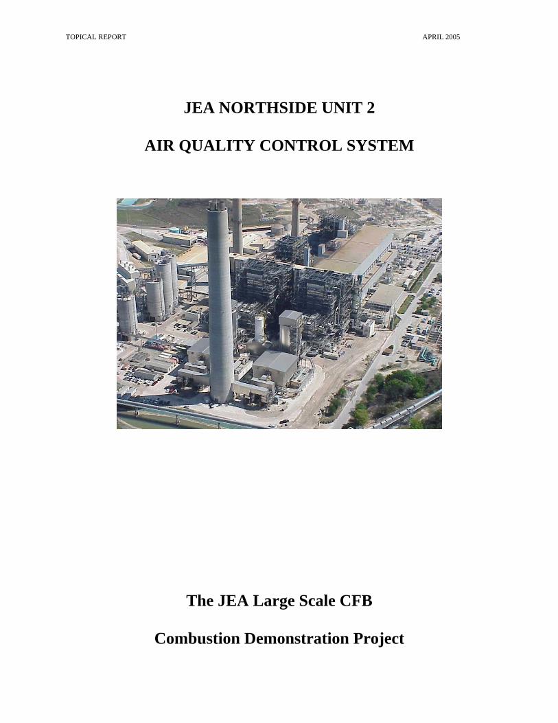
JEA NORTHSIDE UNIT 2
AIR QUALITY CONTROL SYSTEM
The JEA Large Scale CFB
Combustion Demonstration Project

TOPICAL REPORT APRIL 2005
Table of Contents
Dry Scrubbing System Process Description ............................................................................... 1 Spray Dryer Absorber .................................................................................................................. 5 Spray Dryer Absorber Process Control...................................................................................... 6 Pulse Jet Fabric Filter .................................................................................................................. 8 Feed Slurry Preparation System ............................................................................................... 10 Pebble Lime Slaking System ...................................................................................................... 11

JEA Large-Scale CFB Combustion Demonstration Project
AQCS Topical Report p-1
AIR QUALITY CONTROL SYSTEM TOPICAL REPORT
Dry Scrubbing System Process Description As part of a major repowering project undertaken by JEA at the Northside Generating Station, two 300 MW circulating fluidized bed (CFB) boilers were installed in conjunction with two semi-dry spray dryer-absorber (SDA) air quality control systems (AQCS). The AQCS systems were installed as polishing scrubbers to insure removal of up to 98.4 percent of the SO2 produced by the fuel, and to reduce emissions of the trace metals lead, mercury and fluorine. Each AQCS Dry Scrubbing System consists of a Wheelabrator Air Pollution Control (WAPC) 48 ft. diameter SDA followed by an eight compartment JET VIP™ Intermediate Pressure Pulse Jet Fabric Filter (PJFF) as indicated in Figures 1, 2, & 3. A lime-based slurry is atomized into the flue gas using 16 two-fluid nozzles in each SDA. The slurry feed into the SDA consists of lime slurry with boiler fly ash and recycled reaction products collected by the fabric filter. The atomized slurry is mixed with the flue gas. SO2 is initially absorbed into the slurry droplets. The heat of the flue gas evaporates the slurry water and cools the flue gas. SO2 continues to be adsorbed onto the dried slurry surface. Flue gas exits the SDA and is ducted to the fabric filter. Cooling the flue gas condenses some of the mercury and additional trace metals. Solid particulate, additional sulfur dioxide, sulfur trioxide, and trace metals are removed in the fabric filter. Flue gas travels down the inlet plenum and into the eight compartments. The flue gas then flows horizontally across the compartment. The fabric filter bags are 5.25 in. diameter, 23.5 ft long, sewn from PPS felt. The fabric filter bags do not have a membrane coating. The fabric filter is cleaned on-line using intermediate pressure (<35 psig) pulse air. Solids collected in the fabric filter are pneumatically conveyed to a recycle surge bin or to the plant fly ash storage silos. Solids from the recycle surge bin are slurried and blended with additional fresh lime slurry to make up the SDA slurry feed. The solids that fall out of suspension in the SDA are mechanically conveyed directly to the recycle mix tank. The reaction products from the SDA contain excess calcium hydroxide (Ca(OH)2). Recycling the reaction products reduces the requirement for fresh lime slurry feed to the system. Approximately half of the solids collected in the fabric filter are pneumatically conveyed to the fly ash storage silos. The ash is then hydrated and transported as a dense slurry to the byproduct storage area where the product cures and can be reclaimed for beneficial reuse. The total amount of slurry feed to the process is controlled to obtain maximum SO2 removal, while producing a dry product. The system is designed to operate at an SDA outlet temperature set-point of approximately 165oF. This is 30o F above the flue gas adiabatic saturation or wet bulb temperature. The spray dryer absorber is designed to provide twelve (12) seconds flue gas residence time at these conditions. Additional SO2 removal occurs in the fabric filter when the flue gas passes through the built-up filter cake on the fabric filter bags. The fabric filter uses on-line cleaning. Cleaning is initiated

JEA Large-Scale CFB Combustion Demonstration Project
AQCS Topical Report p-2
on reaching a high fabric filter differential pressure setpoint. Two rows of bags in each compartment are pulsed on-line without isolating a fabric filter compartment. This design maximizes the filter cake on the bags, improving SO2 removal across the fabric filter. The design performance conditions for each CFB boiler and Dry Scrubbing System were as follows:
• 6.7% Sulfur Petroleum Coke Fuel
• 85% SO2 Removal in the CFB
• 89.5% SO2 Removal in the SDA/FF
SO2 removal requirements for the SDA/FF range between 70 and 95.1% depending on the fuel fired, the fuel sulfur content, and the SO2 removal in the CFB (75-90%). Cooling the flue gas condenses SO3, Hg, and other heavy metals in the flue gas. These materials can then be collected as an aerosol on the filter cake in the fabric filter. The Dry Scrubbing System emission requirements are listed in Table 1.
TABLE 1 EMISSION REQUIREMENTS
SO2 <0.15 lb/mmbtu NOx <0.09 lb/mmbtu CO <0.22 lb/mmbtu Particulates <0.011 lb/mmbtu PM10 <0.011 lb/mmbtu SO3 1.1 lb/hr Fluoride 0.43 lb/hr Lead 0.070 lb/hr Mercury 0.03 lb/hr VOC 14 lb/hr Opacity <10% Ammonia Slip <40 ppm Steam Flow >1,794 Klb/hr Boiler Efficiency 88.1%

JEA Large-Scale CFB Combustion Demonstration Project
AQCS Topical Report p-3
The Dry Scrubbing System design parameters are listed in Table 2.
TABLE 2 DRY SCRUBBING SYSTEM DESIGN CONDITIONS
Fuel Petroleum Coke Performance
Coal Performance Maximum
Inlet Flue Gas lb/hr 2,630,000 2,576,000 2,724,000 ACFM 831,700 826,000 879,280 °F 280 280 280 Static Pressure in. wg. -20 -19 -22 Sulfur Dioxide ppmv 660 366 1,405 lb/mmBTU 1.42 0.77 3.05 SO2 Removal % 89.4% 80.5% 95.1% Fly Ash gr/ACF 2.9 2.9 2.9 SO3 lb/mmBTU 0.054 0.018 0.054 HF lb/mmBTU 0.016 0.0028 0.0106 Pb lb/mmBTU 0.0028 0.0028 0.0028 Hg lb/mmBTU 1.7x10⁻⁵ 1.7x10⁻⁵ 1.7x10⁻⁵


JEA Large-Scale CFB Combustion Demonstration Project
AQCS Topical Report p-4
Figure 3. JEA Northside Unit 2, WAPC Spray Dryer Absorber/Fabric Filter

JEA Large-Scale CFB Combustion Demonstration Project
AQCS Topical Report p-5
Spray Dryer Absorber Flue gas is ducted from the multiple boiler air heater outlets to the SDA inlet plenum. Flue gas enters the side of the inlet plenum. Ladder vanes turn the gas down into a perforated plate and egg crate flow straightener system. The duct transition/elbow and SDA inlet plenum are designed to create an even gas distribution (plug flow) pattern at the SDA nozzle injection point. See Figure 4. Sixteen (16), multiple-port two-fluid nozzle atomizers spray the feed slurry down into the SDA vessel, parallel to the gas flow. The flue gas and the evaporating slurry droplets pass down through the vessel. The flue gas makes a 90o turn, exits the SDA, and enters the fabric filter (FF). The entire duct system was modeled to optimize gas pressure loss and minimize dust fallout. Each nozzle is provided with a feed lance assembly consisting of a concentric feed pipe (air around slurry), and the nozzle head. The nozzle head is constructed of stainless steel with multiple ceramic inserts. The feed lance assembly is inserted down through the SDA roof (penthouse floor) through a nozzle shroud assembly. See Figures 4 & 5. The feed lance has quick-disconnects for slurry and atomizing air. Each nozzle uses nine - 7 mm diameter abrasion resistant ceramic inserts. Slurry enters through the back of the nozzle head and is distributed to the nine nozzle inserts. Atomizing air enters concentrically into a reservoir in the nozzle head. The atomizing air expands as it passes through the insert. This expansion creates the shear necessary to atomize the slurry. A penthouse enclosure is provided for nozzle and slurry feed system maintenance. If a nozzle requires cleaning, it is accomplished with the unit on-line, without affecting SO2 removal performance. The nozzle is isolated using local slurry shutoff valves, and removed using a chain fall suspended from an overhead trolley/monorail. A spare feed lance is lowered into the shroud and connected. A nozzle can be removed and a spare nozzle installed in approximately five to ten minutes. The flue gas passes to the bottom of the spray dryer absorber and then out of the side of the vessel. The majority of the fly ash entering the spray dryer absorber and the solids generated by the spray dryer absorber are conveyed with the flue gas to the downstream fabric filter. A small portion falls out in the spray dryer absorber hopper. Hopper heaters maintain the hopper plate at the flue gas temperature, minimizing condensation and the buildup of solids.
Figure 4 Spray Dryer Absorber

JEA Large-Scale CFB Combustion Demonstration Project
AQCS Topical Report p-6
Fly ash and reaction products continually exit the SDA through a live bottom and gate airlock, to a drag chain conveyor. The drag chain conveyor transports the material to the Recycle Mix Tank. A delumper is provided on top of the Mix Tank to break up any oversized material. Spray Dryer Absorber Process Control Feed slurry is pumped from the Feed Slurry Transfer Pump to a head tank at the top of each SDA. The head tank provides slurry to the redundant SDA feed pumps located in the SDA penthouse enclosure. See Figure 1. Slurry is distributed to the multiple two fluid nozzles through a header and hose system. The main control loops for the spray dryer absorber are outlet temperature control and stack SO2 concentration. Temperature is measured at the spray dryer outlet by four redundant thermocouples which provide a DCS temperature indication and a feedback signal to the SDA outlet temperature controller. The output from this controller is used as a flow set point (gpm) for the SDA total flow controller. This controller modulates the speed of the Feed Slurry Pump based on a feed back signal from a total flow meter. The SDA design outlet temperature is 165oF. Figure 5. SDA Nozzle

JEA Large-Scale CFB Combustion Demonstration Project
AQCS Topical Report p-7
Alarms are provided to indicate high and low spray dryer absorber outlet temperature. A separate low-low temperature alarm is provided for slurry feed shutdown. Atomizing air flow to each nozzle is controlled at a constant rate by an individual Atomizing Air Flow Controller and is measured by a local flow indicating switch. Low atomizing air flow is alarmed on the DCS and is used to automatically stop slurry flow to a nozzle. SO2 concentration is monitored at the stack. An SO2 controller controls the ratio of fresh lime slurry feed and recycle slurry to the feed slurry pumps. Recycle slurry is made up by mixing water with solids from the Recycle Ash Storage Bin and SDA hopper. The ratio of solids to water is automatically controlled based on a feedback from a density meter.
Figure 6. SDA Penthouse

JEA Large-Scale CFB Combustion Demonstration Project
AQCS Topical Report p-8
Pulse Jet Fabric Filter Flue gas leaves the SDA and immediately enters the fabric filter inlet plenum. The plenum is tapered along its length to maintain gas velocity and to promote gas/duct distribution to the eight compartments. Flue gas leaves through the bottom of the plenum into the bottom side of each compartment. See Figure 7. An automatic compartment inlet damper is provided to isolate the compartment for maintenance. The flue gas flows down through the plenum floor minimize dust fallout. Baffles evenly distribute flue gas and dust into the eight compartments.
Flue gas and particulate is directed upward toward the top of the bags by an internal baffle system in each compartment. Heavier particles are separated from the gas stream before reaching the filter bags. Gas flow on the dirty side of the filter bags is primarily downward. This flow pattern enhances even gas distribution and minimizes dust abrasion and reintrainment when pulsing on line.
BagsInlet
Plenum
OutletPlenum
Removable Roof Door
Pulse Header
Baffle
Figure 7 Fabric Filter

JEA Large-Scale CFB Combustion Demonstration Project
AQCS Topical Report p-9
Each compartment has 1,040, 5.25 in. dia. by 23.5 ft. long PPS felt bags. This provides a total filter surface area of over 250,000 square feet (5.8 acres) of filtering surface. The PPS felt weighs a nominal 16 oz/yd2. The felt is rated at a 375°F maximum continuous operating temperature. This allows the fabric filter and boiler to continue to safely operate if the SDA should trip off line. Each bag is supported on a 9 gauge, 10 wire, two piece cage. The units were designed to operate at a 3.5:1 air to cloth ratio. Bags are cleaned by pulsing with intermediate pressure (35 psig) compressed air. The pulse valves are mounted on four oversized headers per compartment to assure adequate air supply to each pulse valve. Each valve pulses 20 bags. Pulse air travels down the 3.5 in. manifold pipe and is directed into the center of each bag using a nozzle. The size of the discharge orifices from the manifold pipes are varied along its length to provide even cleaning force for each bag. No venturis are required at the top of the bags. The bags are normally cleaned on-line using a pressure loss initiation signal. Two rows of bags are cleaned in a compartment. The sequence then steps to the next compartment and repeats until the pressure loss setpoint is satisfied. The controls also provide for automatic off-line cleaning, manually initiated off-line cleaning, and a timer initiated sequence. Pulsed dust is collected in a pyramidal hopper and is discharged through a 12 in. opening to a pneumatic conveying system. Hopper heaters are provided to minimize dust hang-up on the hopper walls. Fluidizing pads using heated air are installed along the discharge to minimize packing and ratholeing.
Figure 8 FF Cleaning System
The Fabric Filter is sized to allow a compartment to be isolated for maintenance at full boiler load. The compartment inlet/outlet dampers are locked closed. Two roof doors are removed

JEA Large-Scale CFB Combustion Demonstration Project
AQCS Topical Report p-10
from the compartment to allow access to the top of the bags. This allows inspection for failed bags and their replacement.
Feed Slurry Preparation System The feed slurry to the SDA consists of lime slurry from the lime slaking system and recycle slurry prepared by reslurrying flyash and reaction products collected in the SDA/FF. The ratio of the two slurry feeds is modulated to maintain the required outlet SO2 emission concentration. The dried solids from the SDA and FF contain excess Ca(OH)2. Recycling the dried reaction products allows the use of this excess alkalinity, lowering the amount of lime slurry added from the slaking system. Flyash and reaction products collected in the FF are pneumatically conveyed to a recycle ash storage bin. This material is metered to a recycle mix tank. Solids that drop out in the SDA are
mechanically conveyed using a drag conveyor directly to the mix tank. The SDA solids drop through a delumper before entering the tank. The flow of water, lime slurry and solids feed from the recycle surge bin are controlled to make up a 35 wt % slurry concentration. The slurry from the mix tank is pumped to a grit screen to remove any tramp materials (>20 mesh). The slurry then flows by gravity to the recycle slurry storage tank. Two (2) 100% capacity Feed Slurry Transfer Pumps transport the recycle slurry from the storage tank to the head tank at the top of the SDA. Excess slurry overflows the Head Tank back to the Feed Slurry transfer pump inlet. Lime slurry from the lime slurry recirculation loop is added to the recycle slurry at the feed transfer pump inlets. Fresh lime slurry flow is modulated to maintain the required SO2 emission concentration at the FF outlet based on the CEM signal. Redundant variable speed feed slurry pumps are provided at the top of each SDA. The feed slurry pumps pump the combined lime/recycle feed slurry to the
two fluid nozzle atomizers, from the head tank. Calcium carbonate (CaCO3) is fed to the CFB boiler for primary SO2 control. The CaCO3 calcines to form CaO which adsorbs SO2 and forms Calcium Sulfate (CaSO4). The fly ash
JEA Large-Scale CFB Combustion Demonstration Project
AQCS Topical Report p-11
particles leaving the boiler include unreacted CaO. Some of the CaO in the fly ash is slaked to form Ca(OH)2 when the recycled ash is mixed with water to make up the recycle slurry. This further reduces the fresh lime slurry feed to the system. Heated recycle water is used to improve the slaking reaction. A heat exchanger is used to recover waste heat from the atomizing air compressors. An eight hour recycle slurry storage tank is also provided to allow the slaking reaction to continue after the material is degritted. The unit has operated at times using no lime slurry from the slaking system, using only the recovered CaO from the CFB fly ash. Provisions have been made in the ball mill slaking system to utilize CFB bed ash as a sorbent in the future. The CFB bed ash will likely be slurried at the silos and pumped to the ball mills. The grinding action of the mills will free up the surface area of the CaO particles to promote slaking. Pebble Lime Slaking System A common 200% capacity slaking system is provided for both units. Pebble lime delivered by pneumatic self unloading trucks is stored in a single 700 ton, storage silo. Redundant 100% capacity vertical ball mill slaking systems are provided to prepare a lime (Ca(OH)2) slurry. Each slaking system feeds slurry to individual unit lime slurry storage tanks. A dual discharge live bin bottom feeds the two redundant slaking systems. Lime is discharged from the silo live bottom to each slaking system weigh belt feeder. The feeder discharges to a premix chamber where the slaking water is blended with the lime. This discharges to the top of vertical ball mill. The vertical ball mill consists of a lined chamber with a helical screw driven from a top mounted gear box and motor. The screw agitates the ball charge. Slurry overflows the mill to a separator tank. The separator tank is a conical discharge tank with a center vertical baffle plate. The mill recycle pump draws slurry from the bottom of the tank and discharges to the bottom of the mill. The high flow through the tank causes the larger slurry particles to be drawn out the bottom of the tank and to be recycled back into the mill. The slurry with the finer particles makes a 180° turn, under the baffle, at the bottom of the tank. Slurry overflows to the lime slurry transfer tank. A lime slurry transfer pump conveys the slurry to the lime slurry storage tank.