top of engine gaskets, seals, and parts...
TRANSCRIPT

TOP of ENGINETOP of ENGINEGaskets, Seals, and PartsGaskets, Seals, and Parts
OVERHAULOVERHAUL

• TOP: This is a view of the Engine before my major attack on it.
• BOTTOM: This is a view with the Fuel Injector cover removed, as well as the front protection cover.
• You can see the main wire housing, the fuel injector wires, both the left and right throttle body/DK motors and the two pressure regulators, located in the middle front of the picture.
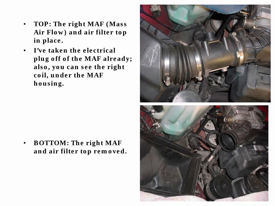
• TOP: The right MAF (Mass Air Flow) and air filter top in place.
• I’ve taken the electrical plug off of the MAF already; also, you can see the right coil, under the MAF housing.
• BOTTOM: The right MAF and air filter top removed.

• TOP: Left MAF, with electrical plug still in place, and air filter top in place.
• BOTTOM: Left MAF and air filter top removed.
• The left coil is to the left of the oil filter housing.

• TOP: The right side Throttle Body (yellow arrow) and DK motor (green arrow) on.
• BOTTOM: The right side Throttle Body and DK motor removed.
• The PCV valve and hoses (arrow) are still in the valve cover.

• TOP: Left side Throttle Body and DK motor on.
• BOTTOM: Left side Throttle Body and DK motor off.
• The left PCV valve is still in the valve cover.

• TOP: Left side fuel injector plugs on.
• To remove the electrical plugs, just push in on the wire clip and pull straight up.
• The silver (looks like a long rectangle aluminum) bar, under the wire housing,is the left side fuel rail.
• BOTTOM: Left side fuel injector plugs removed. I’ve also removed the front and rear brackets that the fuel injector cover is bolted to.

• TOP: Right side fuel injector plugs on.
• You will have the same removal for the electrical plugs.
• BOTTOM: Right side fuel injector plugs removed. I’ve also removed the front and rear brackets that the fuel injector cover is bolted to.
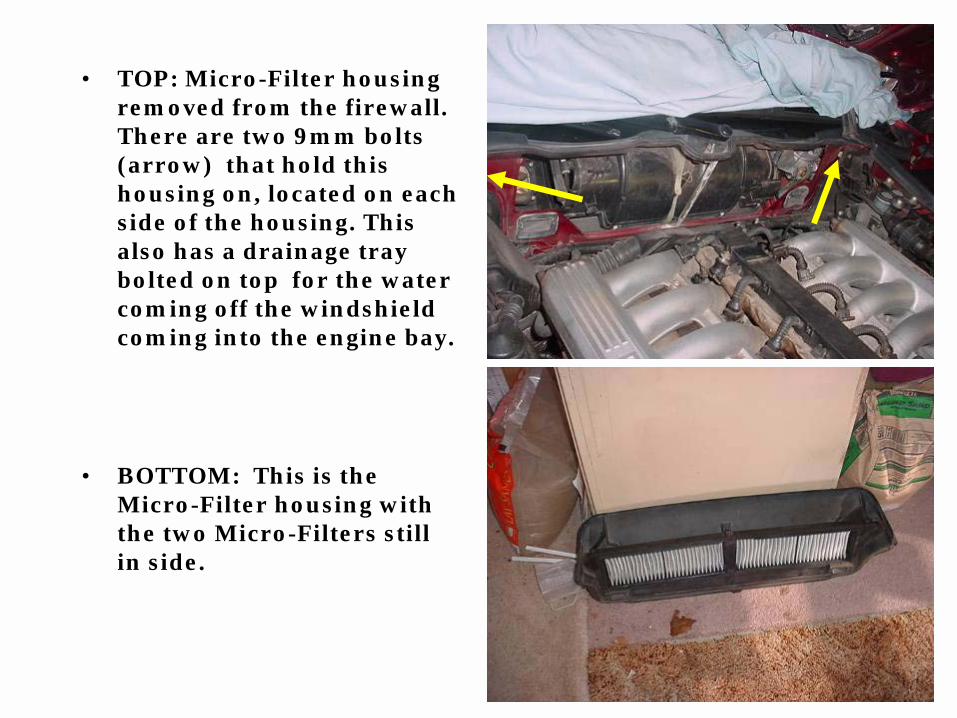
• TOP: Micro-Filter housing removed from the firewall. There are two 9mm bolts (arrow) that hold this housing on, located on each side of the housing. This also has a drainage tray bolted on top for the water coming off the windshield coming into the engine bay.
• BOTTOM: This is the Micro-Filter housing with the two Micro-Filters still in side.

• TOP: These are the rear fuel line hoses (arrow) going to the fuel rail.
• You can’t really see it, but there is another hose under the top hose.
• The top hose goes to the left side fuel rail and the bottom goes over to the right fuel rail.
• BOTTOM: This is a view with the two hoses removed from the two fuel lines.
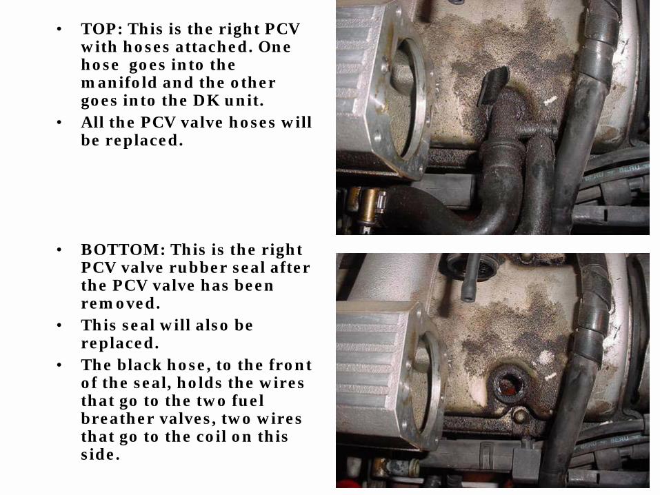
• TOP: This is the right PCV with hoses attached. One hose goes into the manifold and the other goes into the DK unit.
• All the PCV valve hoses will be replaced.
• BOTTOM: This is the right PCV valve rubber seal after the PCV valve has been removed.
• This seal will also be replaced.
• The black hose, to the front of the seal, holds the wires that go to the two fuel breather valves, two wires that go to the coil on this side.

• TOP: This is the left PCV valve with hoses attached.
• BOTTOM: This is the left PCV valve rubber seal after the PCV valve has been removed.
• The black hose, in front of the seal, has the wires that go to the small wire that goes to the alternator, and the two wires that go to the coil.

• This is one of two temperature sensors located at the back of each of the intake manifold, this is the one on the left side.
• BOTTOM: This is a view of the two fuel tank breather valves. One on top has a black connector and the one on the bottom has a tan connector, don’t get these mixed up!
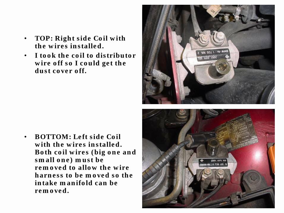
• TOP: Right side Coil with the wires installed.
• I took the coil to distributor wire off so I could get the dust cover off.
• BOTTOM: Left side Coil with the wires installed. Both coil wires (big one and small one) must be removed to allow the wire harness to be moved so the intake manifold can be removed.

• TOP: This is a view of the nut that holds the positive cable on the Alternator, 13mm nut and small wire with 10mm nut; also there is a small wire below. Once you get both the wires off, just pull the small wire up through the rubber cover. This is a PITA to get to, but it’s do-able!
• BOTTOM: This is a view of the cables, and the cover removed from the Alternator. The cover will need to ‘snap’ back on to the bracket; the small wire will need to be pushed through; before you bolt the two cables on and snap the cover back on.
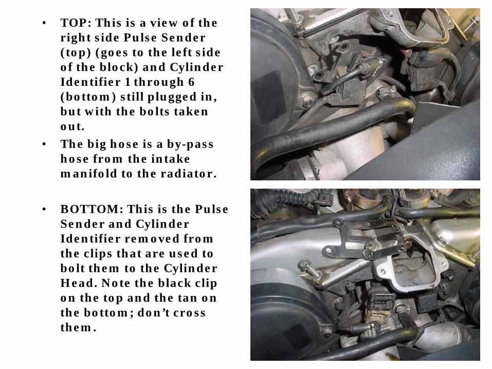
• TOP: This is a view of the right side Pulse Sender (top) (goes to the left side of the block) and Cylinder Identifier 1 through 6 (bottom) still plugged in, but with the bolts taken out.
• The big hose is a by-pass hose from the intake manifold to the radiator.
• BOTTOM: This is the Pulse Sender and Cylinder Identifier removed from the clips that are used to bolt them to the Cylinder Head. Note the black clip on the top and the tan on the bottom; don’t cross them.

• TOP: This is a view of the left side Pulse Sender (top) and Cylinder Identifier 7 through 12 (bottom) with the bolts taken out.
• BOTTOM: This is the Pulse Sender and Cylinder Identifier removed from the clips that are used to bolt them to the Cylinder Head. Note the black clip on the top and the tan on the bottom; don’t cross them.

• TOP: This is the broken Pulse Sender (arrow) for cylinder 1 through 6. Remember even thought it’s on the left side it goes to the right side of the block. This is the only thing I “broke” during the hole operation.
• BOTTOM: I’m pointing at a small plastic nut that holds the back of the electric lead duck on the back of the engine. After all the electrical plugs are loose this is the only thing that is holding the unit on.

• TOP: This is one of the vacuum hoses that goes to the pressure regulator (yellow arrow) on the left side of the engine. It goes to the DK unit.
• All the vacuum hoses will need to be replaced.
• The small wires (red arrow) coming out of the front of the wire housing, between the regulators, go to the pulse senders and cylinder identifiers.
• BOTTOM: This is the electrical lead duct and all the electrical wires that connect to all the sensors and Alternator being held up out of the way of the intake manifold.

• TOP: This is the fuel injector rails with the fuel injector still in place, after the wire housing as been removed.
• BOTTOM: This is one of four bolts (two on each side) that holds the fuel injector on the intake manifold.

• TOP: This is the intake manifold with the fuel rails and the fuel injectors removed
• BOTTOM: Here are the 12 fuel injectors. I’ve taken the upper (the part that fits inside the fuel rail), and lower (the part that fits inside the manifold) O-rings out; they will also need to be replaced.
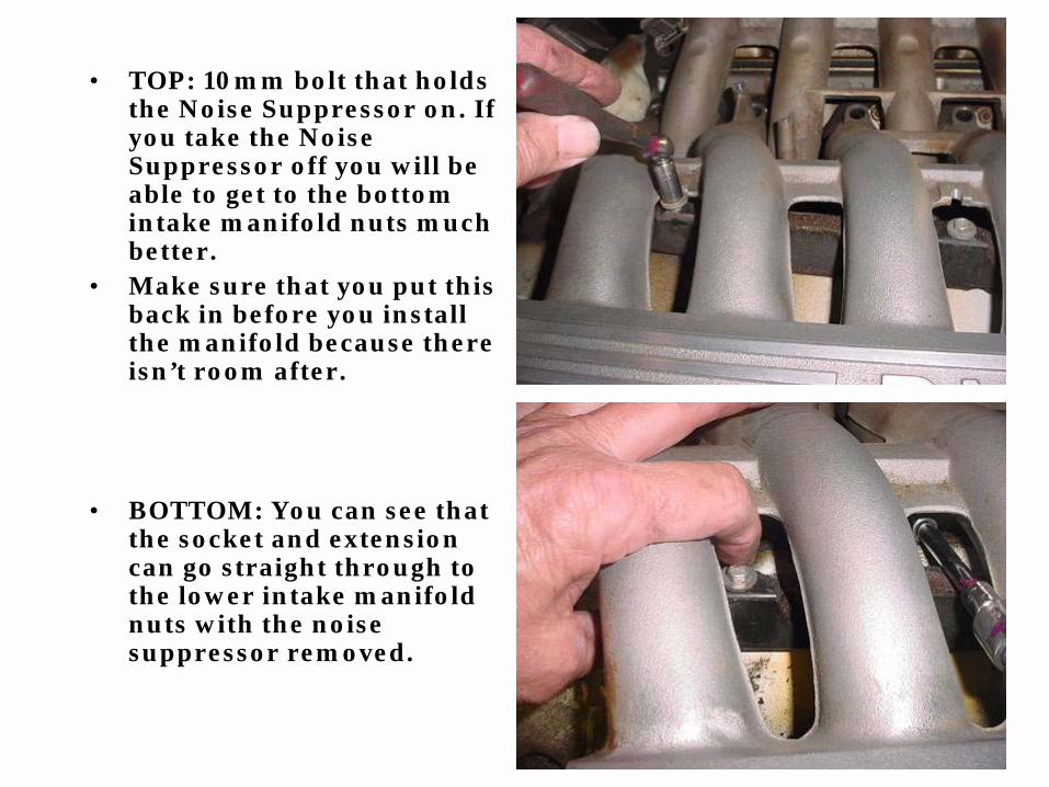
• TOP: 10mm bolt that holds the Noise Suppressor on. If you take the Noise Suppressor off you will be able to get to the bottom intake manifold nuts much better.
• Make sure that you put this back in before you install the manifold because there isn’t room after.
• BOTTOM: You can see that the socket and extension can go straight through to the lower intake manifold nuts with the noise suppressor removed.

• TOP and BOTTOM: As you can see, the bottom bolts are very hard to see and to get to. I used a little grease inside of the 10mm socket to help keep the nut from falling out.
• You really don’t need to worry about the nuts dropping at this point, because once the manifolds are removed you can get to them using a magnet.
• In the top picture; the holes (arrow) to the left of the nuts is where the fuel injectors go.

• TOP: This is 1 of 4 nuts that hold the intake manifold on to the 4 holders located on each outside corner of the valve cover, above the spark plugs.
• BOTTOM: Here is a picture showing the intake manifold gaskets after the removal of the manifold. Be careful as you take the right side manifold off, because of the fuel return line pipes that are held on by two of the manifold nuts.
• The fuel return lines are on the outside of the studs; be careful getting this back on.

• TOP: This is the right side showing the intake manifold gaskets. Note the engine pulling bracket at the front on this side. The two pipes are the return fuel lines that go from the front of the fuel rails to the back of the engine.
• BOTTOM: This is the left side showing the intake manifold gaskets. Not the engine pulling bracket at the back on this side.

• TOP: This is the right side rear intake manifold holder. It is bolted to the valve cover bolt, just like the other 3.
• You will need to make sure that these are lined up straight and tight with they are reinstalled.
• BOTTOM: This is the right side front intake manifold holder. The hole is the right PCV valve.
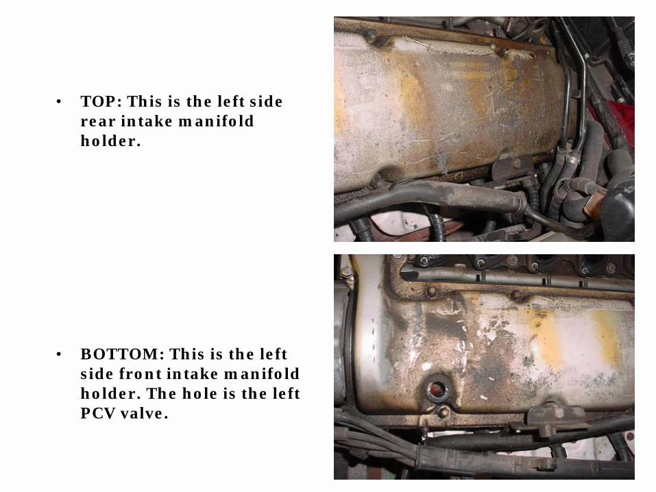
• TOP: This is the left side rear intake manifold holder.
• BOTTOM: This is the left side front intake manifold holder. The hole is the left PCV valve.
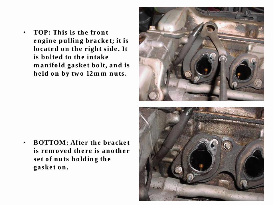
• TOP: This is the front engine pulling bracket; it is located on the right side. It is bolted to the intake manifold gasket bolt, and is held on by two 12mm nuts.
• BOTTOM: After the bracket is removed there is another set of nuts holding the gasket on.

• This is the rear engine pulling bracket; it is located on the left side. It is bolted to the intake manifold gasket bolt, and is held on by two 12mm nuts. Just like the front, after the bracket is removed there is another set of nuts holding the gasket on.

• TOP: This is the right cylinder head with the intake gaskets removed.
• BOTTOM: This is the left cylinder head with the intake gaskets removed.

• Here are the four intake manifold gaskets. The top two are from the right side and the bottom two are from the left side. I don’t think it matters where they go, but because I’m using them I’ll put them back where they were.
• The blue substance around the edges and the bolts is Hylomar (sealer). It will be used on both sides of the intake gaskets and the valve covers when reinstalled.

• TOP: This is on the right rear and it’s the fuel return line. The bolt that holds the bracket on (arrow) is bolted to the valve cover nut.
• BOTTOM: This is after the bracket has been removed (red arrow) and I’m pointing at (yellow arrow) the rear manifold holder, which is also bolted to one of the valve cover nuts.

• TOP: This is the left rear manifold holder, also bolted to the valve cover nut.
• You can see the two fuel hoses (arrows) going to the two fuel lines that go to the fuel rails.
• BOTTOM: This is the left front Manifold holder.
• All four of the bolts that rest on these brackets also will hold the spark plug wire harness (arrow), one on each side of the head.

• TOP: This is the left cylinder head with the valve cover removed.
• I will take the four banjo bolts (arrow) and the oil line (pipe) off and clean them. Then using new crush washers, ‘blue’locktite on the bolts, and torque the nuts back on.
• BOTTOM: this is the right cylinder head with the valve cover removed.
• I’ve put paper towels inside of each of the intake ports to help keep the inside clean.

THIS IS WHAT I’VE DONE UP TO THIS POINT:
Removed the fuel injector coverRemoved both MAF sensors, air filters and top housingsRemoved both throttle bodies and DK motorsRemoved the fuel injector plugs from the injectorsRemoved the Micro-filter housing from the firewallRemoved all the various fuel hoses from their connectorsRemoved both the PCV valves, seals, and hosesRemoved both temperature sensor and fuel tank breather valve plugsRemoved both (small and large) coil wires and coil to distributor wiresRemoved both (small and large) alternator wires from the back of the alternatorRemoved both the pulse senders and the cylinder identifiers plugsRemoved the all the electrical wires and the complete housing off of the manifoldRemoved both of the fuel injector railsRemoved all twelve of the fuel injectorsRemoved both of the intake manifoldsRemoved the four intake manifold gasketsRemoved the two valve coversRemoved the eight banjo bolts and the two oil lines I’ve cleaned all the major parts; both intake manifolds, both valve covers, all nuts and bolts, and the parts that will go back onI’ve painted both intake manifolds and polished the BMW lettersI’ve painted both valve coversI’ve painted all the parts that will be going back on

• TOP: This is the left intake manifold after being cleaned, the runners painted silver and the plenum being painted black.
• BOTTOM: This is the right intake manifold after I’ve polished the BMW and horizontal lines.

• TOP: Here are the two intake manifolds ready to be reinstalled.
• BOTTOM: Here are the two valve covers after being painted black. I’ve installed the PCV valve seals and the covers are ready to be installed.

• Here are the eight banjo bolts and the two oil lines after being cleaned.
• When I put these back on I’ll put new crush washers on as well.

• TOP: As you can see, the bottom pipe shows the holes that are between the banjo bolts. Make sure all these holes are cleaned out before putting them back on.
• BOTTOM: Here are the banjo bolts, with the blue locktite on, ready to go back on the head.

• TOP: This is the right side spark plug wire harness; removing this makes it easer to reinstall the valve cover.
• Besides the plug wires (first six wires, from the left), there is the coil wire and the 1-6 cylinder identifier, and the distributor cap (arrows).
• BOTTOM: This is the left side spark plug wire harness.
• It has the same wires as the right side has.

• TOP: Here are both the distributor housings with the rotor caps (arrows) still in place.
• I’ll be taking both the housing off so I can replace the gaskets and seals.
• BOTTOM: Here, I’ve installed the valve covers but I haven’t put the nuts back on yet.

• TOP: I’m taking the three bolts out of the rotor using a 3mm Allen wrench
• BOTTOM: I’m taking the rotor off of the drive flange

• TOP: Using a 6mm Allen socket I’m taking the drive flange bolt out of the end of the camshaft.
• BOTTOM: I’m taking the bolt out of the drive flange at this point.

• TOP: This what happens to the inside cover with you try and ‘pry’ the drive flange off.
• I had to use a pry bar, going from one side to the other to get the drive flange off. I should have used a puller, but because I pushed on the plastic (BMW ‘old’ plastic is very ‘brittle’ and breaks very easy) and broke it I just did the same to both sides. I will replace the inside covers.
• BOTTOM: This is the drive flange being removed; there is a small pin that needs to be lined up to a hole on the end of the camshaft.

• TOP: Using a 5mm Allen socket I’m taking the three bolts out of the Distributor housing.
• BOTTOM: I’m taking the Distributor housing off of the cylinder head.

• Here is a view of both the cylinder heads with the parts removed
• I still haven’t put the valve cover nuts/bolts on. I will take the valve cover back off before putting everything back together.
• This is the crankshaft speed sensor (arrow) that became disenable during the tear-down.

• TOP: This is the Distributor housing gasket (green arrow) and inside is the oil seal (black arrow).
• Both of these (one each for both sides) will be replaced.
• BOTTOM: Going clockwise, these are the two drive flanges, two rotors, one drive flange bolt, and six Distributor housing bolts.

• TOP: Here I’m knocking the seal out of the housing, using a large socket and a plastic hammer.
• BOTTOM: Here I’m putting the seal back in, using the same socket.
• Make sure that the ‘lip’ is facing the back of the housing.

• TOP: This is a view of the old seal (left) and the new seal (inside the housing on the right).
• BOTTOM: This is the new gasket that goes on the back of the housings.

• This is a picture of both the distributor housings, with the inside covers, and rotors, installed on the front of both the heads.
• The new left and right PCV Valves and hoses (yellow arrow) are also ready to be installed into the new seals (green arrow).
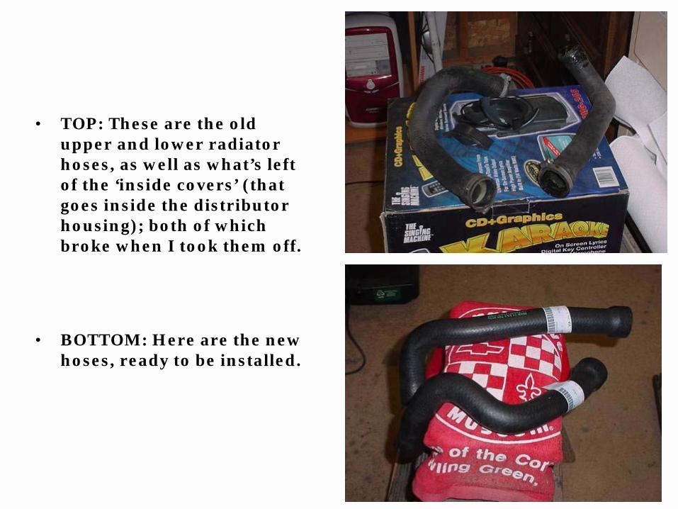
• TOP: These are the old upper and lower radiator hoses, as well as what’s left of the ‘inside covers’ (that goes inside the distributor housing); both of which broke when I took them off.
• BOTTOM: Here are the new hoses, ready to be installed.
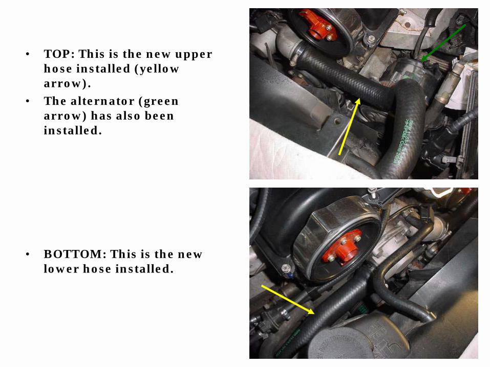
• TOP: This is the new upper hose installed (yellow arrow).
• The alternator (green arrow) has also been installed.
• BOTTOM: This is the new lower hose installed.

• TOP: This is a view of the Alternator Ribbed Belt, after I took it off.
• This is a ‘crack’ all the way across the belt. It was just a matter of time before it BROKE!
• BOTTOM: This is a view of the A/C Ribbed Belt, after I took it off.
• As you can see, it has ‘cracks’ all along it’s edges.

• TOP: Here are the two new Ribbed Belts ready to put on.
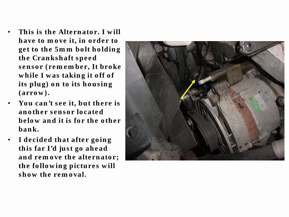
• This is the Alternator. I will have to move it, in order to get to the 5mm bolt holding the Crankshaft speed sensor (remember, It broke while I was taking it off of its plug) on to its housing (arrow).
• You can’t see it, but there is another sensor located below and it is for the other bank.
• I decided that after going this far I’d just go ahead and remove the alternator; the following pictures will show the removal.

• TOP: This is the bottom bolt that holds the adjusting pulley on to the bottom of the block.
• BOTTOM: This is the adjusting pulley after it was removed for the block.
• I’ve left it at this position to show how it will be put back on.
• I will also be replacing both the Alternator and water pump V-belts.

• TOP: This is the bottom bolt (13mm), one of three, that holds the Alternator on.
• I had to remove the Alternator V-belt in order to get the Alternator off.
• The belt (arrow) is around the power steering pump and also goes around the water pump.
• BOTTOM: Here is the ‘hole’where the Alternator was. Note the bracket (yellow arrow) that the Alternator is attached to.
• The V-belt (red arrow) runs the water pump; one of two V-belts used on the engine.
• Also, I had to remove the upper radiator hose. This is the intake neck (white arrow).

• TOP: This is a view of the Alternator on its back. This is about the position it is in when on the engine.
• BOTTOM: Here, the alternator is placed on its top; this, because I wanted to show the position of the cooling duck, to help in putting it back on the right way.

• TOP: Here is a picture of the distributor covers after I’ve cleaned, sanded and polished them.
• BOTTOM: Here are the two distributor covers installed on the front of the heads.

• TOP: This is the back of the throttle body and the DK motor.
• I’m going to take both sides apart and clean/check them and make sure they are working properly.
• BOTTOM: Here are the five Philips head screws (yellow arrow) and the one T-30 Torx tip bolt (red arrow), along with the one ‘odd’ tip bolt (green arrow) needed to be removed in order to take the cover off.

• TOP: I had to use a small set of vise grip pliers to take this bolt out, as I didn’t have a tool to do it.
• This is the only bolt that was like this on the throttle body/KD unit.
• BOTTOM: Here is the ‘different’ bolt used above compared to the T 30 Torx bolt used.
• I will have to get two of the T 30 Torx bolts to replace these bolts.

• TOP: Here is the throttle body (yellow arrow, DK/armature housing (red arrow), and the armature (green arrow).
• BOTTOM: This is the inside of the DK/ armature housing.
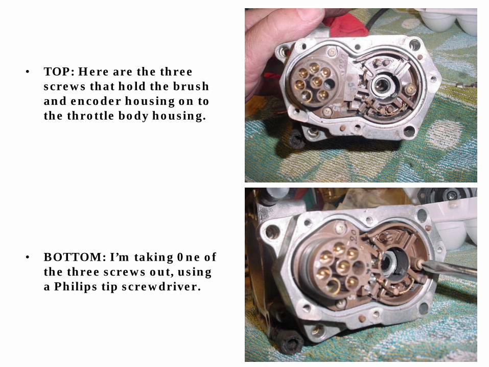
• TOP: Here are the three screws that hold the brush and encoder housing on to the throttle body housing.
• BOTTOM: I’m taking 0ne of the three screws out, using a Philips tip screwdriver.

• TOP: Here I’ve taken the brush/encoder housing off of the throttle body housing.
• If you should decide to go deeper into to throttle body, be careful of the position of the encoder wiper (arrow).
• BOTTOM: Here is a picture of the encoder wiper in the ‘correct’ position inside the throttle body housing.

• TOP:This is showing the commulator before it is cleaned.
• BOTTOM: Here I’m cleaning the groves in the commulator.
• I will put some grease on the tip of the shaft and re-insert this unit bck into the housing.

• TOP: This area is where the oil filter housing goes.
• The arrow shows the area that the bolts go that hold the housing on.
• BOTTOM: Here is the oil filter housing (top arrow) and the cap (bottom arrow) after being cleaned, polished.

•TOP: This is the wire harness getting ready to be cleaned, before being put back on.
•BOTTOM: This is the four intake manifold gaskets after being cleaned.
•They are ready for the Hylomar sealer to be installed to both sides.
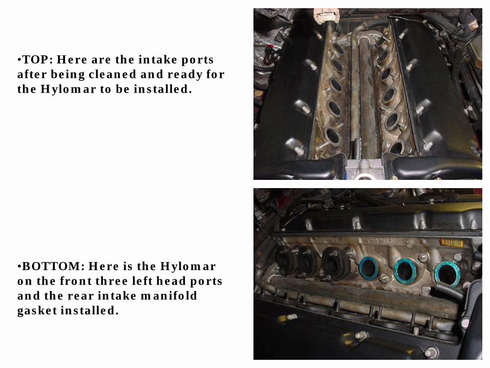
•TOP: Here are the intake ports after being cleaned and ready for the Hylomar to be installed.
•BOTTOM: Here is the Hylomar on the front three left head ports and the rear intake manifold gasket installed.
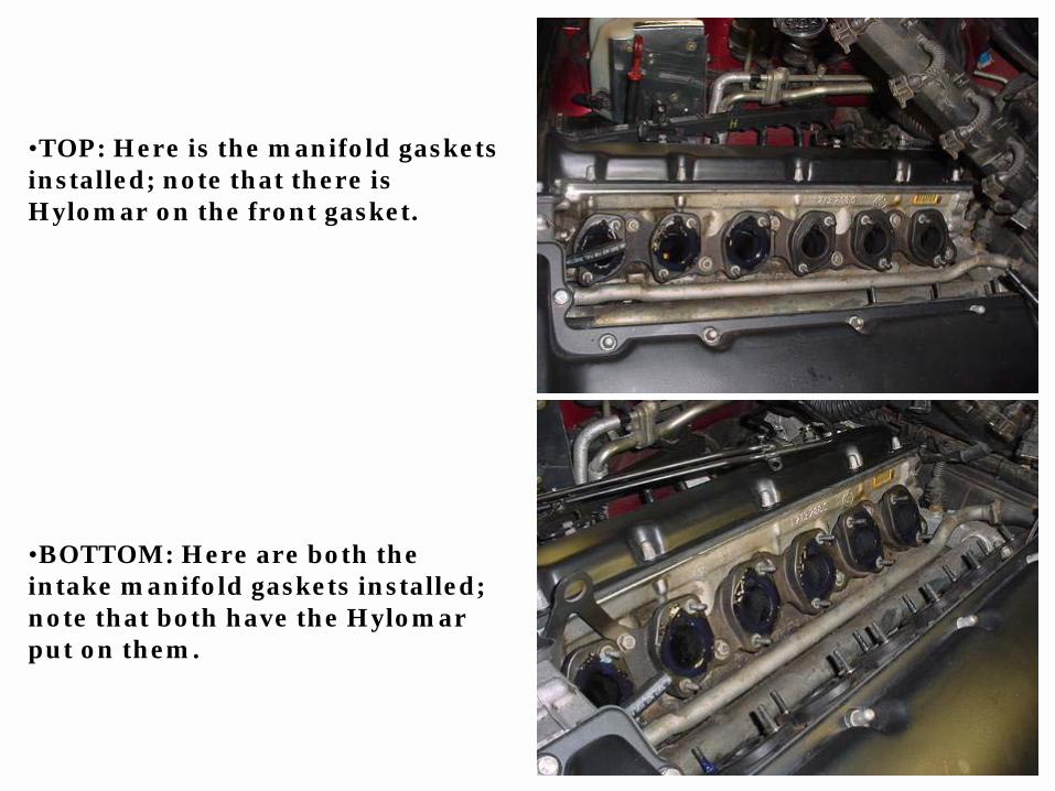
•TOP: Here is the manifold gaskets installed; note that there is Hylomar on the front gasket.
•BOTTOM: Here are both the intake manifold gaskets installed; note that both have the Hylomar put on them.

•TOP: This is the right intake manifold installed.
•Remember to put the fuel return line on before putting the nuts back on (arrows).
•BOTTOM: Here are both the intake manifolds installed. (I only lost one nut; I just got a new one because I didn’t want to waste time trying to find it under there!)

•TOP: Here is the twelve fuel injectors after being installed into the two fuel rails.
•BOTTOM: Here are the fuel rails (with the fuel injectors) installed into both the intake manifolds.

•TOP: This is the right throttle body/DK unit installed.
•All fuel and vacuum hoses have been installed as well as all the electrical connections on this side.
•BOTTOM: This is the left throttle body/DK unit installed; again all fuel and vacuum hose and electrical connections have been installed.

• TOP: Here are the two (large and small) alternator wires, with the rubber protector, installed.
• The small wire was broken and I had to ‘splice’ a new wire on.
• By removing the oil filter housing, it was much easer to get to this area.
• BOTTOM: This is a front view of the engine after both throttle body/DK motors installed.

• Here are two pictures of the engine, after putting everything put back on.

• TOP: This is a view of the right side of the engine, after all the part have been installed.
• BOTTOM: This is a view of the left side of the engine, after all the part have been installed.

• TOP: This is a picture of the engine before all this work was started.
• BOTTOM: This is a picture of the engine after all this work was done.