tooth fillet profile optimization for gears with symmetric and asymmetric
TRANSCRIPT

TOOTH FILLET PROFILE OPTIMIZATION FOR GEARS WITH SYMMETRIC AND ASYMMETRIC TEETH
Alex Kapelevich, AKGears, LLC and Yuriy Shekhtman, One Step Molding Solution INTRODUCTION
Historically, gear geometry improvement efforts were concentrated on the working involute flanks. They are nominally well described and classified by different standard accuracy grades, depending on gear application and defining their tolerance limits for such parameters as runout, profile, lead, pitch variation, and others. Working involute flanks are also modified to localize a bearing contact and provide required performance at different tolerance combinations and possible misalignment as a result of operating conditions (temperature, loads, etc.). Their accuracy is thoroughly controlled by gear inspection machines. The gear tooth fillet is an area of maximum bending stress concentration. However, its profile and accuracy are marginally defined on the gear drawing by typically very generous root diameter tolerance and, in some cases, by the minimum fillet radius, which is difficult to inspect. In fact, tooth bending strength improvement is usually provided by gear technology (case hardening and shot peening to create compressive residual stress layer, for example) rather than gear geometry.
Fig. 1. Gear tooth fillet generation by the rack cutter (gear hob); 1 –
cutter tooth tip; 2 – gear tooth fillet, as a trajectory of the cutter tooth tip; α - rack profile (pressure) angle; A – addendum; C – radial clearance; R –
cutter tip radius.
The gear tooth fillet profile is typically determined by the generating cutting tool (gear hob or shaper cutter) tooth tip trajectory (Fig. 1), also called the trochoid. If the cutter parameters are chosen or designed to generate the involute flank profile, which must work for the specific gear application and satisfy certain operation conditions, the fillet profile is just a byproduct of the cutter motion. The fillet profile and, as a result, bending stress are also dependent on the cutter radial clearance and tip radius. The standard radial clearance usually is 0.25/P or 0.20/P+0.002”, where P is the standard diametral pitch. The standard cutter tooth radius for the coarse pitch gears is 0.3/P. For the fine

pitch gears the standard cutter tooth radius is not standardized and can be as low as zero [1]. Unlike the contact Hertz stress, the bending stress does not define the major dimensions or the gears, such as pitch diameters or center distance. If the calculated bending stress is too high, in many cases, the number or teeth can be reduced and the coarser diametral pitch (larger module) can be applied to keep the same pitch diameters, center distance, and the same (or close) gear ratio. This makes the gear tooth physically larger and reduces bending stress to an acceptable level. Of course, this increases specific sliding and reduces contact ratio and gear mesh efficiency, but this is better than the broken teeth. There are two general approaches to reducing bending stress for the given tooth size. One of them is to alter the generating cutter tooth tip — most common application of this approach is the rack with the full tip radius. Another approach is to alter the gear tooth fillet profile — the most common application here is the circular (instead of trochoid) fillet. Further development of both these approaches is based on a mathematical function fitting technique where the cutter tip radius or the gear tooth trochoid fillet profile is replaced by a parabola, ellipsis, chain curve, or other curve, reducing the bending stress (see for example [2, 3]). Bending stress reduction achieved by such fillet profile improvement is varied and greatly depends on the cutter or gear tooth parameters. The resulting tooth fillet profile must be checked for interference with the mating gear at various gear (and center distance) tolerance combinations. This paper presents the Direct Gear Design fillet profile optimization technique, which allows for a substantial bending stress reduction in comparison to traditionally designed gears. It also describes how bending stress reduction can produce other gear performance benefits. OPTIMIZATION METHOD Direct Gear Design [4] defines all gear geometry parameters without using the pre-selected basic or generating rack. It is applied for custom gears and allows for the separation of the active involute flank and tooth fillet design. The flank profiles are designed first to satisfy primary performance requirements, such as maximum load capacity with acceptable contact stress level, maximum gear mesh efficiency (minimum specific sliding), etc. The tooth fillet design is based on completely defined involute flank parameters. The initial fillet profile is a trajectory of the mating gear tooth tip in the tight (zero backlash) mesh. For practical purposes, this trajectory is defined at the minimum center distance (including both gears’ runout), maximum tooth thickness, and maximum outer diameter of the external mating gear (for an internal mating gear the minimum inner diameter is used). This allows the exclusion of interference with the mating gear tooth. The fillet optimization consists of three major components [5]:
- trigonometric functions for fillet profile approximation; - FEA for stress calculation; - a random search method to define the optimal set of the trigonometric
functions’ coefficients, which allows them to reach the minimum bending stress.
a
b
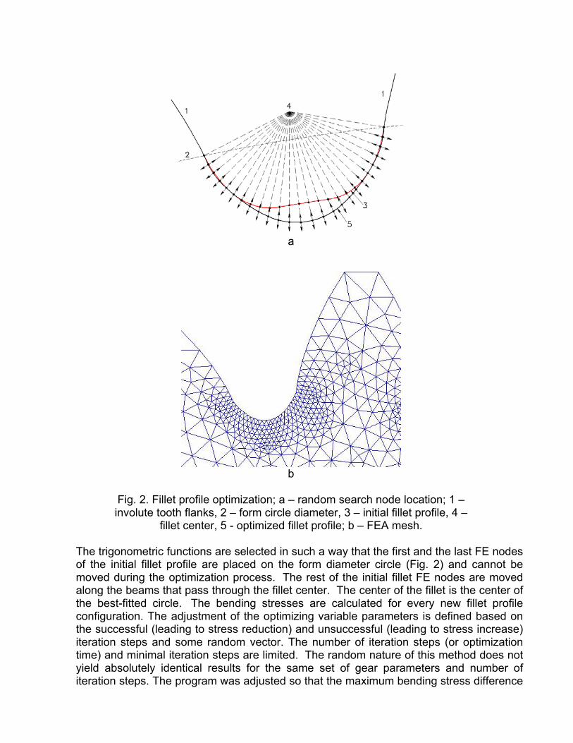
Fig. 2. Fillet profile optimization; a – random search node location; 1 – involute tooth flanks, 2 – form circle diameter, 3 – initial fillet profile, 4 –
fillet center, 5 - optimized fillet profile; b – FEA mesh.
The trigonometric functions are selected in such a way that the first and the last FE nodes of the initial fillet profile are placed on the form diameter circle (Fig. 2) and cannot be moved during the optimization process. The rest of the initial fillet FE nodes are moved along the beams that pass through the fillet center. The center of the fillet is the center of the best-fitted circle. The bending stresses are calculated for every new fillet profile configuration. The adjustment of the optimizing variable parameters is defined based on the successful (leading to stress reduction) and unsuccessful (leading to stress increase) iteration steps and some random vector. The number of iteration steps (or optimization time) and minimal iteration steps are limited. The random nature of this method does not yield absolutely identical results for the same set of gear parameters and number of iteration steps. The program was adjusted so that the maximum bending stress difference

between repeated calculations does not exceed 2%. The fillet shapes for these cases are also slightly different. OPTIMIZATION RESULTS As an example of the fillet profile optimization, different fillets were constructed for the gear pair with the standard involute tooth profile and the following parameters (see Fig. 3):
- Number of teeth of both mating gears – 24; - Diametral Pitch – 12; - Generating rack profile (pressure) angle – 20o; - Addendum coefficient (a.k.a. Normalized Addendum coefficient) – 1.0; - Face width of both mating gears – 1.0”; - Operating torque – 200 in-lb.
Fig. 3. Standard gear tooth with different fillets; X and Y coordinates at the center of the gear; F – applied load; H – radial distance between load application and max. stress points; C – actual radial clearance; 1 – fillet profile (black) generated by the standard (for coarse diametral pitch) rack with the tip radius 0.3/P; 2 – fillet profile (pink) generated by the standard (for fine diametral pitch) rack with the tip radius equal zero; 3 – fillet profile (dark blue)generated by the full tip radius rack; 4 - circular fillet profile (light blue); 5 – optimized fillet profile (green); 6 – trajectory of the mating gear tooth tip in tight mesh (red).
Table 1 presents the FEA of the different fillet profiles. It also indicates that the optimized fillet has the largest curvature radius at the maximum stress point and the
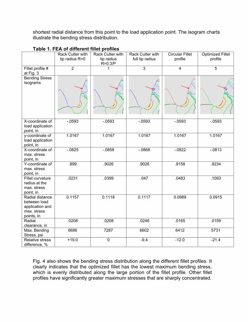
shortest radial distance from this point to the load application point. The isogram charts illustrate the bending stress distribution. Table 1. FEA of different fillet profiles
Rack Cutter with tip radius R=0
Rack Cutter with tip radius R=0.3/P
Rack Cutter with full tip radius
Circular Fillet profile
Optimized Fillet profile
Fillet profile # at Fig. 3
2
1
3
4
5
Bending Stress Isograms
X-coordinate of load application point, in
-.0593 -.0593 -.0593 -.0593 -.0593
y-coordinate of load application point, in
1.0167 1.0167 1.0167 1.0167 1.0167
X-coordinate of max. stress point, in
-.0825 -.0858 -.0868 -.0822 -.0813
Y-coordinate of max. stress point, in
.899 .9026 .9026 .9158 .9234
Fillet curvature radius at the max. stress point, in
.0231 .0399 .047 .0483 .1093
Radial distance between load application and max. stress points, in
0.1157 0.1118 0.1117 0.0989 0.0915
Radial clearance, in
.0208 .0208 .0246 .0165 .0159
Max. Bending Stress, psi
8686 7287 6602 6412 5731
Relative stress difference, %
+19.0 0 -9.4 -12.0 -21.4
Fig. 4 also shows the bending stress distribution along the different fillet profiles. It clearly indicates that the optimized fillet has the lowest maximum bending stress, which is evenly distributed along the large portion of the fillet profile. Other fillet profiles have significantly greater maximum stresses that are sharply concentrated.

Fig. 4. Bending stress distribution chart along the fillet profiles. 1 – fillet profile (black) generated by the standard (for coarse diametral pitch) rack with the tip radius 0.3/P; 2 – fillet profile (pink) generated by the standard (for fine diametral pitch) rack with the tip radius equal zero; 3 – fillet profile (dark blue) generated by the full tip radius rack; 4 - circular fillet profile (light blue); 5 – optimized fillet profile (green).
BENEFITS OF FILLET OPTIMIZATION If load capacity of the gears with conventional (trochoidal or circular) fillet profiles is limited by the maximum bending stress, the fillet optimization increases gear load capacity proportionally to the bending stress reduction. However, very often, gear load capacity, and consequently gear drive size and weight reduction, is limited by the tooth surface durability, which greatly depends on the contact stress. In this case, the bending stress reduction provided by the fillet optimization can be converted into the contact stress reduction. The Fig. 5a presents the charts of the bending (black) and contact (blue) stresses, calculated for the gear pairs with the standard involute profiles. These gears have gear ratio 1:1, the constant center distance aw = 60 mm, the face width of both gears b = 10 mm, and the driving torque T = 50 Nm. The number of teeth varies from 12 to 75 and module varies accordingly from 5 mm to 0.8 mm to keep the constant center distance. The bending stresses are presented in two charts; one for the gears with the standard (generated by 20o pressure angle rack) trochoidal fillet profile and another one for the gears with the optimized fillet profile. For example, the bending stress level of 180 MPa is considered acceptable. This level is achievable for the 20-tooth gears with the standard fillet or for the 28 tooth gears (with finer module). However, the 28 tooth gears have a higher contact ratio and as a result lower contact stress. The

fillet optimization allowed converting potential bending stress into the 6% contact stress reduction by using the gears with greater number of teeth. This 6% contact stress reduction doubles life of the steel case hardened gears with a high number of load cycles.
Fig. 5. a – contact stress reduction; b – increased mesh efficiency.
Similarly to the conversion of the bending stress reduction into contact stress reduction and longer life, the fillet optimization allows achieving higher gear mesh efficiency. The Fig. 5b presents the charts of the bending stresses (black) and gear mesh efficiency (blue) for the same gear pairs. In this example, the finer module gears with greater number of teeth and the optimized fillet, which have the same maximum bending stress level, provide less specific profile sliding and, as a result, 0.6% higher gear mesh efficiency in one gear pair. This can be very beneficial for high power multistage gear transmission, because this will reduce heat generation, required lubrication system, etc. The potential benefits of the bending stress concentration reduction by the tooth fillet profile optimization can be extended. This allows using a gear with a greater

number of teeth and finer module that generates less noise and vibration. It is likely possible to increase the hydrodynamic oil film thickness and reduce the flash temperature, because of the reduced profile sliding. APPLICATION OF FILLET OPTIMIZATION FOR SYMMETRIC AND ASYMMETRIC GEARS
The fillet profile optimization is for custom gears. In previous paragraphs, the optimized fillets were constructed to the standard involute tooth flanks only to compare them with the fillet profiles of the standard gear teeth and demonstrate possible bending stress concentration reduction. The authors have no intention of recommending using fillet optimization for standard gears. The benefits of the standard gears include their universality and suitability to the majority of non-critical gear applications. They are available off-the-shelf; their design validation is simple and typically does not require special testing. In custom gears the nonstandard gear geometry, including the optimized fillet profile, is necessary to guarantee required performance. Custom gears are used for extreme and highly competitive applications like aerospace and racing drives, automotive gear transmissions, etc. Forming gear technology, like plastic and metal injection molding, powder metal processing, precision gear forging, extrusion, and die casting allow to extend the implementation of the nonstandard gears with the optimized fillet profile for many custom gear application. Examples, of such gears are presented in the Fig. 6.
a b
Fig. 6. Examples of the custom gears with the optimized fillet profile; a – polyurethane die cast gear for industrial application; b – metal machined
gears for automotive application. Many gear applications, like for propulsion drives, have one main direction for the torque transmission. The design intent of asymmetric gear teeth is to improve performance of the primary drive profiles at the expense of the performance for the opposite coast profiles. The coast profiles are unloaded or lightly loaded during a relatively short work period. The main advantage of asymmetric gears is contact stress reduction on the drive flanks, resulting in higher torque density (load capacity per gear size). Another important advantage is the possibility to design

the coast flanks and fillet independently from the drive flanks, managing the tooth bending strength and stiffness, and load sharing. Asymmetric gear geometry [6] is not defined or limited by any standards. This makes asymmetric gears naturally suitable for tooth fillet optimization. Fig. 7 presents the asymmetric gear with the optimized fillet profile.
a b
c
Fig. 7. Asymmetric gear with the optimized fillet profile; a – FEA mesh, b – stress isograms, c – experimental gear for aerospace application
The tooth fillet profile optimization is applicable for all kinds of involute (and non-involute) gears including spur, helical, bevel, face, worm gears, etc. The fillet profile is optimized in the normal section of the tooth and then it can be protruded or swapped to define the complete gear tooth.
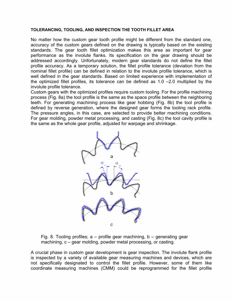
TOLERANCING, TOOLING, AND INSPECTION THE TOOTH FILLET AREA No matter how the custom gear tooth profile might be different from the standard one, accuracy of the custom gears defined on the drawing is typically based on the existing standards. The gear tooth fillet optimization makes this area as important for gear performance as the involute flanks. Its specification on the gear drawing should be addressed accordingly. Unfortunately, modern gear standards do not define the fillet profile accuracy. As a temporary solution, the fillet profile tolerance (deviation from the nominal fillet profile) can be defined in relation to the involute profile tolerance, which is well defined in the gear standards. Based on limited experience with implementation of the optimized fillet profiles, its tolerance can be defined as 1.0 –2.0 multiplied by the involute profile tolerance. Custom gears with the optimized profiles require custom tooling. For the profile machining process (Fig. 8a) the tool profile is the same as the space profile between the neighboring teeth. For generating machining process like gear hobbing (Fig. 8b) the tool profile is defined by reverse generation, where the designed gear forms the tooling rack profile. The pressure angles, in this case, are selected to provide better machining conditions. For gear molding, powder metal processing, and casting (Fig. 8c) the tool cavity profile is the same as the whole gear profile, adjusted for warpage and shrinkage.
Fig. 8. Tooling profiles; a – profile gear machining, b – generating gear machining, c – gear molding, powder metal processing, or casting.
A crucial phase in custom gear development is gear inspection. The involute flank profile is inspected by a variety of available gear measuring machines and devices, which are not specifically designated to control the fillet profile. However, some of them like coordinate measuring machines (CMM) could be reprogrammed for the fillet profile

inspection. Optical inspection devices like ToolScope (or SmartScope) are also suitable for this purpose. CONCLUSIONS
- The article presented the Direct Gear Design tooth fillet profile optimization method;
- The tooth fillet profile optimization provides significant (10-20%) bending stress reduction in comparison with traditionally defined tooth fillet profiles;
- The bending stress reduction provided by the fillet optimization can be converted into other gear performance benefits, such as the contact stress reduction and increased gear mesh efficiency;
- Presented implementation example of the gears with the optimized fillet profile; - Considered approaches to the tolerancing, tooling, and inspection of the gears with
the optimized fillet profile. REFERENCES
1. Townsend D.P. Dudley’s Gear Handbook, McGraw-Hill, 1991. 2. DER HOVANESIAN J., ERICKSON M. A., HATHAWAY R. B.,
SAVOYARD J. P. JR, Gear root stress optimization using photoelastic optimization techniques, SAE transactions ISSN 0096-736X, 1989, vol. 97 (4), pp. 748-755
3. Pulley F.T., M.W. Kipling, G.A. Matson, D.L. Thurman, B.W. Avery “Method for producing and controlling a fillet on a gear”, US Patent #6164880, 2000.
4. Kapelevich A. L., “Direct Design Approach for High Performance Gear Transmissions”, Gear Solutions, December 2007, 22-31. This article was presented at the Global Powertrain Congress 2007 June 17-19, 2007, Berlin, Germany and published in the Global Powertrain Congress Proceedings, Vol. 39-42, 66-71.
5. Kapelevich A. L., Shekhtman Y. V., “Direct Gear Design: Bending Stress Minimization”, Gear Technology, September/October 2003, 44 – 49.
6. Kapelevich A.L., “Geometry and design of involute spur gears with asymmetric teeth”, Mechanism and Machine Theory, 2000, Issue 35, pp. 117-130.
AUTHORS Dr. Alexander L. Kapelevich is the owner of the consulting firm AKGears, LLC, developer of modern Direct Gear Design® methodology and software. He has thirty years of experience in gear transmission development. Dr. Kapelevich can be reached by e-mail at [email protected]. Dr. Yuriy Shekhtman is an expert in mathematical modeling and stress analysis with a 40-year experience. He created a number of computer programs based on FEA and other numerical methods. Dr. Shekhtman is a software developer for AKGears. He can be reached by e-mail at [email protected]