tools for intel® x86/x64 - lauterbach · la-4607 quadprobe-intel-x86 (for la-4616) tools for...
TRANSCRIPT

Tools for Intel® x86/x64
TRACE32 Online Help
TRACE32 Directory
TRACE32 Index
TRACE32 Documents ......................................................................................................................
ICD In-Circuit Debugger ................................................................................................................
Processor Architecture Manuals ..............................................................................................
x86 ............................................................................................................................................
Tools for Intel® x86/x64 ....................................................................................................... 1
Introduction ....................................................................................................................... 2
Legend ................................................................................................................................ 2
TRACE32 QuadProbe ........................................................................................................ 3
QuadProbe and PowerDebug Module USB 3.0 4
Delivery Content 4
Assembling 6
Extra (CONV-MIPI60Q-XDP60) 9
Extras (POWER Connector) 9
Extra (USB-2-CABLE) 10
Extra (TRIGGER-CONNECTOR) 10
QuadProbe and PowerDebug PRO 11
Delivery Content 11
Assembling 13
Extra (CONV-MIPI60Q-XDP60) 16
Extras (POWER Connector) 16
Extra (USB-2-CABLE) 17
Extra (TRIGGER-CONNECTOR) 17
Extra ................................................................................................................................... 18
Extra (USB-2-CABLE) 18
Extras (TRIGGER-CONNECTOR) 19
Tools for Intel® x86/x64 1 ©1989-2020 Lauterbach GmbH

Tools for Intel® x86/x64
Version 21-Feb-2020
Introduction
This manual presents the delivery content for the individual Lauterbach tools for Intel® x86/x64 and describes how the individual components are assembled to a ready-to-use debug tool.
Legend
Most TRACE32 products have on their back a sticker that provide identification information. The order code and the subsequent product name printed there are used in the delivery content photos to identify the individual products.
Some products are additionally marked as Variant. Variant means, there is an alternative for the shown product, which is functionally identical.
Some products are additionally marked as Extra. Extra products are delivered as standard, however, are not required in the default configuration. When these products are needed and how they are integrated into the configuration, is described in an extra chapter.
Tools for Intel® x86/x64 2 ©1989-2020 Lauterbach GmbH
TRACE32 QuadProbe
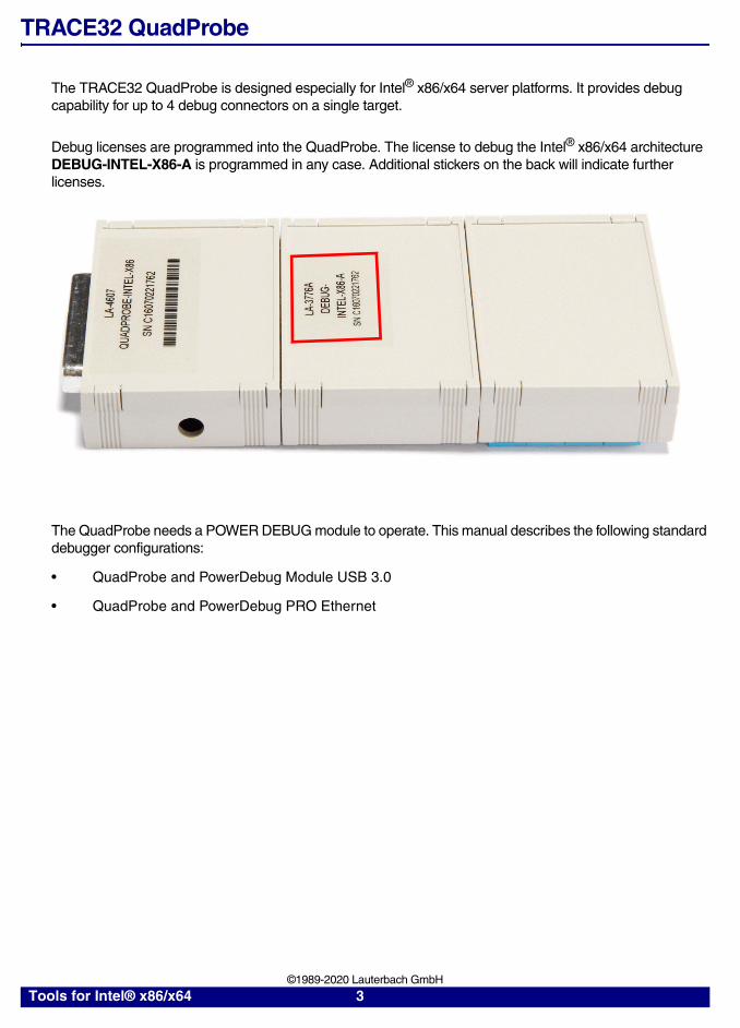
The TRACE32 QuadProbe is designed especially for Intel® x86/x64 server platforms. It provides debug capability for up to 4 debug connectors on a single target.
Debug licenses are programmed into the QuadProbe. The license to debug the Intel® x86/x64 architecture DEBUG-INTEL-X86-A is programmed in any case. Additional stickers on the back will indicate further licenses.
The QuadProbe needs a POWER DEBUG module to operate. This manual describes the following standard debugger configurations:
• QuadProbe and PowerDebug Module USB 3.0
• QuadProbe and PowerDebug PRO Ethernet
Tools for Intel® x86/x64 3 ©1989-2020 Lauterbach GmbH

QuadProbe and PowerDebug Module USB 3.0
Delivery Content
In order to assemble a “QuadProbe and PowerDebug Module USB 3.0” debugger you need:
Package QP Intel x86/x64 Single MIPI60-Q
Deliveries of LA-4614 “Package QP Intel x86/x64 Single MIPI60-Q” or LA-4616 “Package QP Intel x86/x64 Single MIPI60-Q Long” comprise the following parts:
lf you want to use more than a single WHISKER-QP-MIPI60-Q, you need further sets comprising of:
• LA-4611 — WHISKER-QP-MIPI60-Q
• LA-1248 or LA-1249 — flex extension cable
• LA-3879 (optional) — converter to XDP60 pin-out
LA-4611 WHISKER-QP-MIPI60-Q LA-1248 FLEXEXT-SAM-QTH-QSHM (8 inch)(for LA-4614)
Variant: LA-1249 FLEXEXT-SAM-QTH-QSHE (24 inch)
Extra: LA-3879 CONV-MIPI60Q-XDP60
LA-4607 QUADPROBE-INTEL-X86
(for LA-4616)
Tools for Intel® x86/x64 4 ©1989-2020 Lauterbach GmbH
PowerDebug Module USB 3.0
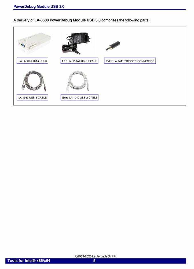
A delivery of LA-3500 PowerDebug Module USB 3.0 comprises the following parts:
LA-3500 DEBUG-USB3 Extra: LA-7411 TRIGGER-CONNECTOR LA-1952 POWERSUPPLY-PP
LA-1943 USB-3-CABLE Extra:LA-1942 USB-2-CABLE
Tools for Intel® x86/x64 5 ©1989-2020 Lauterbach GmbH

Assembling
1. Assemble the QUADPROBE.
Connect the flex extension cable to the WHISKER-QP-MIPI60-Q.
Connect the WHISKER-QP-MIPI60-Q to the QUADPROBE.
The QUADPROBE provides 4 sockets for the WHISKER-QP-MIPI60-Q cables. The outer socket is socket A. The first WHISKER-QP-MIPI60-Q has to be connected to this socket.
If you are using more than one WHISKER-QP-MIPI60-Q the assembling order is as follows:
The second WHISKER-QP-MIPI60-Q has to be connected to socket B.
The third WHISKER-QP-MIPI60-Q has to be connected to socket C.
The fourth WHISKER-QP-MIPI60-Q has to be connected to socket D.
QUADPROBE WHISKER-QP-MIPI60-Q
LAU
TER
BA
CH
LAU
TER
BA
CH
CD
CABLE
B A
QU
ADPR
OB
E
DEB
UG
CA
BLE
POW
ER7-
9V
QU
ADPR
OB
EM
IPI6
0-Q
LAU
TER
BA
CH
LAU
TER
BA
CH
C B AD
Tools for Intel® x86/x64 6 ©1989-2020 Lauterbach GmbH

2. Connect the QUADPROBE to the POWER DEBUG INTERFACE / USB 3.
3. Connect the USB cable to POWER DEBUG INTERFACE / USB 3. Then connect the power supply to POWER DEBUG INTERFACE / USB 3 to power the tool.
Tools for Intel® x86/x64 7 ©1989-2020 Lauterbach GmbH

4. Connect the tool, respectively the WHISKER-QP-MIPI60-Q to your target.
For the standard assembling it is presumed that your target provides one or more
“Intel® MIPI60 Converged” connectors, you can connect the WHISKER-QP-MIPI60-Q cables via the flex extension cable directly.
If your target provides one or more Intel® XDP60 connectors, please refer to “Extra (CONV-MIPI60Q-XDP60)”, page 9.
If the “Intel® MIPI60 Converged” connectors are numbered in ascending order, it is recommended:
- to connect the WHISKER-QP-MIPI60-Q connected to the QUADPROBE socket A to the connector with the lowest number.
- to connect the WHISKER-QP-MIPI60-Q connected to the QUADPROBE socket B to the connector with the next higher number and so on.
5. Start the TRACE32 software.
6. Power your target.
Information on how to set up your debug environment can be found in the following manuals:
• “Intel® Application Note for Server Setup” (app_x86_server.pdf)
• “Intel® x86/x64 Debugger” (debugger_x86.pdf).
Tools for Intel® x86/x64 8 ©1989-2020 Lauterbach GmbH

Extra (CONV-MIPI60Q-XDP60)
If your target provides one or more Intel® XDP60 connectors, you have to use the converter
CONV-MIPI60Q-XDP60. It converts the “Intel® MIPI60 Converged” pinout from the
WHISKER-QP-MIPI60-Q to Intel® XDP60 pinout.
Connect CONV-MIPI60Q-XDP60 to each flex extension cable for each WHISKER-QP-MIPI60-Q.
Then continue as described on the previous page.
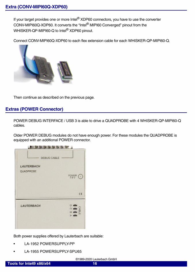
Extras (POWER Connector)
POWER DEBUG INTERFACE / USB 3 is able to drive a QUADPROBE with 4 WHISKER-QP-MIPI60-Q cables.
Older POWER DEBUG modules do not have enough power. For these modules the QUADPROBE is equipped with an additional POWER connector.
Both power supplies offered by Lauterbach are suitable:
• LA-1952 POWERSUPPLY-PP
• LA-1955 POWERSUPPLY-SPU65
Tools for Intel® x86/x64 9 ©1989-2020 Lauterbach GmbH

Extra (USB-2-CABLE)
For more information refer to “Extra (USB-2-CABLE)”, page 18.
Extra (TRIGGER-CONNECTOR)
For more information refer to “Extras (TRIGGER-CONNECTOR)”, page 19.
Tools for Intel® x86/x64 10 ©1989-2020 Lauterbach GmbH

QuadProbe and PowerDebug PRO
Delivery Content
In order to assemble a “QuadProbe and PowerDebug PRO” debugger, you need:
Package QP Intel x86/x64 Single MIPI60-Q
Deliveries of LA-4614 “Package QP Intel x86/x64 Single MIPI60-Q” or LA-4616 “Package QP Intel x86/x64 Single MIPI60-Q Long” comprise the following parts:
lf you want to use more than a single WHISKER-QP-MIPI60-Q, you need further sets comprising of:
• LA-4611 — WHISKER-QP-MIPI60-Q
• LA-1248 or LA-1249 — flex extension cable
• LA-3879 (optional) — converter to XDP60 pin-out
LA-4611 WHISKER-QP-MIPI60-Q LA-1248 FLEXEXT-SAM-QTH-QSHM (8 inch)(for LA-4614)
Variant: LA-1249 FLEXEXT-SAM-QTH-QSHE (24 inch)
Extra: LA-3879 CONV-MIPI60Q-XDP60
LA-4607 QUADPROBE-INTEL-X86
(for LA-4616)
Tools for Intel® x86/x64 11 ©1989-2020 Lauterbach GmbH

PowerDebug PRO Ethernet
LA-3505 POWER-DEBUG-PRO Extra: LA-7411 TRIGGER-CONNECTOR LA-1955 POWERSUPPLY-SPU65
LA-1943 USB-3-CABLE Extra:LA-1942 USB-2-CABLE
Tools for Intel® x86/x64 12 ©1989-2020 Lauterbach GmbH

Assembling
1. Assemble the QUADPROBE.
Connect the flex extension cable to the WHISKER-QP-MIPI60-Q.
Connect the WHISKER-QP-MIPI60-Q to the QUADPROBE.
The QUADPROBE provides 4 sockets for the WHISKER-QP-MIPI60-Q cables. The outer socket is socket A. The first WHISKER-QP-MIPI60-Q has to be connected to this socket.
If you are using more than one WHISKER-QP-MIPI60-Q the assembling order is as follows:
The second WHISKER-QP-MIPI60-Q has to be connected to socket B.
The third WHISKER-QP-MIPI60-Q has to be connected to socket C.
The fourth WHISKER-QP-MIPI60-Q has to be connected to socket D.
QUADPROBE WHISKER-QP-MIPI60-Q
LA
UT
ER
BA
CH
LA
UT
ER
BA
CH
CD
CABLE
B A
QU
AD
PR
OB
E
DE
BU
G C
AB
LE
PO
WE
R7-
9V
QU
AD
PR
OB
EM
IPI6
0-Q
LA
UT
ER
BA
CH
LA
UT
ER
BA
CH
C B AD
Tools for Intel® x86/x64 13 ©1989-2020 Lauterbach GmbH

2. Connect the QUADPROBE to POWER-DEBUG-PRO.
3. Connect the USB cable or a etherent cable to POWER DEBUG PRO.
The Lauterbach standard delivery does not contain an ethernet cable.
Then connect the power supply to POWER DEBUG PRO to power the tool.
Tools for Intel® x86/x64 14 ©1989-2020 Lauterbach GmbH

4. Connect the tool, respectively the WHISKER-QP-MIPI60-Q to your target.
For the standard assembling it is presumed that your target provides one or more
“Intel® MIPI60 Converged” connectors, you can connect the WHISKER-QP-MIPI60-Q cables via the flex extension cable directly.
If your target provides one or more Intel® XDP60 connectors, please refer to “Extra (CONV-MIPI60Q-XDP60)”, page 9.
If the “Intel® MIPI60 Converged” connectors are numbered in ascending order, it is recommended:
- To connect the WHISKER-QP-MIPI60-Q connected to the QUADPROBE socket A to the connector with the lowest number.
- To connect the WHISKER-QP-MIPI60-Q connected to the QUADPROBE socket B to the connector with the next higher number and so on.
5. Start the TRACE32 software.
6. Power your target.
Information on how to set up your debug environment can be found in the following manuals:
• “Intel® Application Note for Server Setup” (app_x86_server.pdf)
• “Intel® x86/x64 Debugger” (debugger_x86.pdf).
Tools for Intel® x86/x64 15 ©1989-2020 Lauterbach GmbH
Extra (CONV-MIPI60Q-XDP60)
If your target provides one or more Intel® XDP60 connectors, you have to use the converter
CONV-MIPI60Q-XDP60. It converts the “Intel® MIPI60 Converged” pinout from the
WHISKER-QP-MIPI60-Q to Intel® XDP60 pinout.
Connect CONV-MIPI60Q-XDP60 to each flex extension cable for each WHISKER-QP-MIPI60-Q.
Then continue as described on the previous page.
Extras (POWER Connector)
POWER DEBUG INTERFACE / USB 3 is able to drive a QUADPROBE with 4 WHISKER-QP-MIPI60-Q cables.
Older POWER DEBUG modules do not have enough power. For these modules the QUADPROBE is equipped with an additional POWER connector.
Both power supplies offered by Lauterbach are suitable:
• LA-1952 POWERSUPPLY-PP
• LA-1955 POWERSUPPLY-SPU65
Tools for Intel® x86/x64 16 ©1989-2020 Lauterbach GmbH

Extra (USB-2-CABLE)
For more information refer to “Extra (USB-2-CABLE)”, page 18.
Extra (TRIGGER-CONNECTOR)
For more information refer to “Extras (TRIGGER-CONNECTOR)”, page 19.
Tools for Intel® x86/x64 17 ©1989-2020 Lauterbach GmbH

Extra
Extra (USB-2-CABLE)
If your host computer does not provide a USB 3.0 interface or if the USB 3 communication is weak, you can use USB-2-CABLE as an alternative.
Use Interface Config from the Misc menu to open an IFCONFIG window. Use the TEST button to test the communication quality. Lauterbach considers the connection to be weak if the warp 16 value is smaller than 100 MB.
Tools for Intel® x86/x64 18 ©1989-2020 Lauterbach GmbH

Extras (TRIGGER-CONNECTOR)
All Lauterbach POWER DEBUG modules provides a TRIG input/output. If this TRIG input/output is connected to the target:
• a trigger generated by TRACE32 can be used to trigger an external device e.g. a logic analyzer.
• a trigger generated by the target can be used to trigger TRACE32.
To use the TRIGGER-CONNECTOR, proceed as follows:
1. Build a trigger cable.
Open the BLACK COVER of the TRIGGER CONNECTOR.
2. Solder the signal cable to SNG and the ground cable to GND.
GND
SNG
Tools for Intel® x86/x64 19 ©1989-2020 Lauterbach GmbH

3. Connect the trigger jack to the TRIG connector of POWER DEBUG module.
4. Connect the signal cable and the ground cable to the external device/target.
The configuration of the trigger within TRACE32 is done via the TRBUS command group.
Tools for Intel® x86/x64 20 ©1989-2020 Lauterbach GmbH