tonyw.h.sheui,s.f.tsai,andt.p.chiang ...homepage.ntu.edu.tw/~twhsheu/member/paper/50-1999.pdf ·...
TRANSCRIPT

Numerical Heat Transfer, Part A, 35:797 ± 814, 1999
Copyright Q 1999 Taylor & Francis
1040 ± 7782 rrrrr 99 $12.00 H .00
NUMERICAL STUDY OF HEAT TRANSFERIN TWO-ROW HEAT EXCHANGERS HAVINGEXTENDED FIN SURFACES
Tony W. H. Sheui, S. F. Tsai, and T. P. ChiangDepartment of Naval Architecture and Ocean Engineering,National Taiwan University, 73 Chou-Shan Road, Taipei, Taiwan ,
Republic of China
This paper reports on a three-dimensional study of air through two-row cylinder tubes. The
analysis is intended to present a comparison of numerical and experimental data to validate
the laminar flow postulation . The current study explores the influence of four perforated fin
surfaces on the pressure drop and heat transfer rate. To gain further insight into the
three-dimensional vortical flow structure, we conduct a topological study of the velocity field.
Examination of the surface flow topology and the flow patterns at cross-flow planes sheds
some light on the complex interaction of the cylinder tube with the mainstream flow. This
study clearly reveals a saddle point in front of the first row of cylinder tubes.
Also clearly revealed by the computed solution s is a flow reversal found in the wake of the
tube. The character of the critical-point-induced flow is also addressed. This study shows
that the addition of perforated fins is not without deficiency. There is, in fact, a trade-off
between the benefit of having an improved heat transfer and the penalty of having an
increased pressure drop.
INTRODUCTION
The present study was undertaken in order to gain a more comprehensive
understanding of the effect of fin types used in conjugate heat exchangers on the
heat transfer between the gas and the fin. Among fins, which can be classified
mainly as plain, corrugated, punched, and slotted types, slotted fins have received
considerable attention and seen increasing use. The main reason slotted fins can
provide heat transfer enhancement is the secondary flow formation, which aidsmixing of flow in the transverse plane. The other important factor is the repeated
formation-destruction of the thin boundary layer flow.
Among the various fins in existence, we consider slotted fins because of their
wider popularity. Slotted fins can be divided into louvered, Forgo, radial-strip,
parallel-strip, and wavy-strip types. Among these, wavy- and parallel-strip fins are
probably the most attractive. The flow pattern is considered to be complex even inthe geometrically simplest plate-fin heat exchanger. The physical complexity comes
from the three-dimensional boundary layer development and the subsequent flow
separation. The introduction of slotted fins adds further complications. Experimen-
Received 13 September 1998; accepted 2 December 1998.
Financial support was made available by the Teco Electric & Machinery Co. Ltd. We are glad to
have this opportunity to acknowledge this support and to record our thanks.
Address correspondence to Professor Tony W. H. Sheu, Institute of Naval Architecture, National
Taiwan University, 73 Chou-Shan Road, Taipei Taiwan, Republic of China.
797

T. W. H. SHEU ET AL.798
NOMENCLATURE
2A maximum flow area of a cell, m P span-averaged pressure, Pa2 2A minimum flow area in a cell, m q heat flux, W r mÇc
2 2A transfer area of a cell, m q span-averaged heat flux, W r mÇf p
B tube pitch, m Re Reynolds numbers .c specific heat of the air, J r kg K T temperature, Kp
D tube diameter, m u velocity component along ii
D hydraulic diameter, m direction, m r sh
H spacing between two plates, m U inlet velocity of the air, m r s2s . s .k thermal conductivity, W r m K a thermal diffusivity s k r r c , m r sp
L streamwise length of the channel, m D P pressure drop, Pa
m flow rate of the air, kg r s D Q span-averaged heat transfer rate,ÇNu Nusselt number J r s
2Nu span-averaged Nusselt number n kinematic viscosity, m r s3p pressure, Pa r density of the air, kg r m
tal investigation of conjugate heat transfer in regions between two fin surfaces is
w xstill a challenging task. In fact, according to Fiebig et al. 1, 2 , no experimentalmethod exists that allows measurement of heat transfer in a finned-tube element.
The alternative to experimental study is to numerically solve the governing
equations for the working media. With the advent of cost-effective high-speed
computers and computational models that have evolved to a high level of sophisti-
cation and reliability, it is now possible to simulate heat transfer characteristics of
finned-tube heat exchangers. In the literature, only a limited number of publica-tions focus on three-dimensional simulations of the slotted-fin heat transfer
problem. The goal for the present work was to assess the performance of wavy-strip
and parallel-strip type fins. This is regarded as the first step toward improvement of
existing designs and thus reduction of the heat exchanger size.
The remainder of this paper is organized as follows. Working equations and
the problem specifications are given in the next section. This is followed by a briefoutline of the segregated solution algorithm, which was devised to compute the
finite volume discretization equations in an iterative manner. To present a clear
picture of the vortical flow structure, we choose limiting streamlines in our
topology study. The numerical results, along with the validation study, and conclu-
sions are presented in the remaining sections.
THEORETICAL ANALYSIS
Using a user-prescribed convective heat transfer coefficient on the fin sur-
face, computation of heat transfer can be performed with little effort, making
design of heat exchangers a practical alternative. One can also apply a moresophisticated model to obtain a detailed account of the complex physics involved in
the flow passage . In order to predict essentially all possible flow and heat transfer
features, we simultaneously work with the convective heat transfer problem for the
working fluid and the heat conduction problem for the fin itself.

HEAT TRANSFER IN TWO-ROW HEAT EXCHANGERS 799
We consider here a Newtonian fluid with constant properties. The equations
of motion that govern the fluid are Navier-Stokes equations and the kinematiccondition that the velocity be divergence-free. The inherent nature of the problem
under investigation warrants full unsteady, three-dimensional calculations that can
be quite expensive. The results shown below lend credence to the assumption of
steady state analysis. Numerical modeling of the flow field in V was thus per-
formed under the steady and laminar assumptions:
u is .s 0 1
xi
1 p 2 u is . s .u u s y q n 2m i x r x x xm i m m
s .where u are the velocity components i s 1 ] 3 and p is the pressure. For thisi
study, the flow under investigation was characterized by the Reynolds number,
defined as Re s u H r n . Here H is the spacing between two fins, while u is the` `
inlet free-stream velocity, which enters the physical domain having a cross-sec-tional area of H = B. The rationale behind adopting the velocity-pressure formula-
s . s .tion is that we can solve the set of equations, Eqs. 1 ] 2 , with well-posed
boundary conditions to determine the fluid flow and heat transfer fields.
FINITE VOLUME METHOD AND SOLUTION ALGORITHM
To conduct an analysis that is amenable to computer simulation, we begin by
transforming the working equations into their algebraic counterparts. The present
incompressible flow analysis was conducted on staggered grids to avoid even-odd
w xpressure oscillations 3 . It is the velocity, which is offset by a half mesh size in its
respective coordinate direction from the pressure, that adds considerable complex-
ity to the programming.Use of primitive variables to simulate incompressible Navier-Stokes equa-
tions may further complicate the analysis. Complications are due to the absence of
pressure in the continuity equation. Not only will this absence tend to increase the
condition number for the discrete system, but it will also cause more zero diagonals
to occur. The resulting lack of diagonal dominance presents difficulties in the use
of iterative solvers to solve for the algebraic system of equations. To overcomethese difficulties, a segregated solution algorithm that is currently in widespread
use is considered to be compensation for the mixed formulation. In the segregated
formulation, working equations are solved in a strongly decoupled fashion. Satis-
faction of the continuity equation is accomplished through increasingly improved
pressure solutions. The correction of the pressure, which is governed by the
Poisson equation, corresponds to incorporating the incompressibility constraintinto the formulation. The storage demand for matrix equations is thus considerably
reduced. Without loss of stability, this semi-implicit solution algorithm provides the
same steady state solution but at much lower computational cost than does the
equivalent mixed formulation.

T. W. H. SHEU ET AL.800
Under conditions where grid lines are skewed to streamlines, false diffusion
errors cause the prediction accuracy to deteriorate. Care must be taken; otherwise,the simulation quality may be seriously harmed by the added cross-wind diffusion
errors. Deterioration of accuracy is particularly severe under high-Re circum-
stances. To remedy this defect, nonlinear flux terms are discretized using upwind
w xschemes. We apply here the QUICK scheme 4 in the domain that has been
nonuniformly discretized. As was the case with the elliptic problem, both diffusive
fluxes and pressure gradients are approximated by means of a second-ordercentered scheme.
Because of geometric complexity, the study of a heat exchanger with ex-
tended fin surfaces has traditionally been a time-consuming effort, employing such
techniques as coordinate transformation . However, it is now well accepted that
discretization errors arising from curvilinear coordinate transformation are gener-
ally considerable and hard to resolve for problems involving highly curved gridlines. Thus, we conduct analysis here in the Cartesian coordinate system so as to
predict physically realistic results with less computational effort.
PROBLEM DESCRIPTION AND BOUNDARY CONDITION
Depending on the application area, we can choose from integrating one-row
or two-row cylinder tubes into the heat exchanger shown in Figure 1. Because of
the lack of space, no consideration is given here to determine whether or not heat
exchangers with two-row coils will outperform those with one-row coils. Our
attention is simply directed toward dealing with two-row coils. A schematic illustra-
tion of the physical problem shown in Figure 2 reveals that vertical tubes ofcircular cross r sections are staggered with respect to each other. In the arrange-
Figure 1. Schematic of two-row fin and tube heat
exchanger.

HEAT TRANSFER IN TWO-ROW HEAT EXCHANGERS 801
ment of these tubes, the centroids of three adjacent tubes form an equilateral
triangle. This fin-tube configuration is characterized by H r D s 0.187, B r D s 2.72,and L r D s 1.693 for a fixed value of H s 1.4 mm.
In this study, airflow with a free-stream velocity of u approaches the inlet`
plane, which is upstream of the leading edge of the fin by a distance of 4.5 mm.
The proper streamwise location at which the inlet velocity profile is applied is a
subject requiring further investigation and will not be addressed here. At fin
surfaces where no-slip boundary conditions apply, pressure boundary condition isnot permitted. In the numerical simulation of inflow-outflow problems, it is of
necessity to truncate the physical domain at a synthetic outlet so as to reduce the
computational expense. We prescribe here the parallel flow at the synthetic plane,
which is 5 mm downstream of the trailing edge of the fin. At the outlet plane, we
apply a zero temperature gradient, since this plane has been shown to be suffi-
ciently far away from the fin surface. In order to solve the energy equation
T 2Ts . s .q u T s a 3m t x x xm m m
s .we prescribe fixed temperatures at the tube surface T s 323 K and at the inlettube
with T s 300 K. At the two vertical walls, the periodic condition is prescribed toin
allow analysis to be conducted in the dotted area shown in Figure 1.
Figure 2. A finned-tube element as module geometry for the investigation.
Included in this figure are also prescribed boundary conditions.

T. W. H. SHEU ET AL.802
RESULTS AND DISCUSSION
As a validation study of the analysis code, we consider first a much simpler
problem that involves a plate fin surface shown in Figure 1. It is the geometricsimplicity that simplifies the analysis and also facilitates illustration of the flow
structure. The Re under investigation is in the range of 83 ( Re ( 258, which isD
defined by the inlet velocities given in Figure 3. In this study, all the analyses were
conducted on 142 = 84 = 40 grids for the case with plate fins and on 142 = 84 = 54
grids for the slotted cases. For accurately capturing the temperature and velocity
boundary layers, nodal points, shown in Figure 4, are nonuniformly distributedalong the x, y, z directions, respectively.
Before any computational results can be deemed reliable enough to illumi-
nate the physical phenomenon, the computational results must be justified through
the grid-independent tests. To this end, we have conducted the grid-independence
study simply for the plate fin case to avoid the geometric complication. Three gridss .142 = 84 = 40, 82 = 43 = 40, 42 = 23 = 40 have been attempted, from whichthe computed heat transfer rates are plotted in Figure 5. As this figure shows, we
are led to know that grids of resolution 142 = 84 = 40 are sufficient to provide
Figure 3. Definitions of Reynolds numbers and running flow conditions.

HEAT TRANSFER IN TWO-ROW HEAT EXCHANGERS 803
Figure 4. Grids used for the present plate fin heat transfer analysis.
grid-independent solutions both for flow and heat transfer characteristics. Figures
6 and 7 show that the experimental data agree well with the computed data in the
investigated Re range, not only for the heat transfer rate, but also for the pressure
drop. As Re was increased further, the deviation between the two sets of databecame appreciable. We are currently trying to confirm whether this deviation is
susceptible to the lack of turbulence modeling.
To gain a better understanding of flow physics and heat transfer characteris-
tics in the conjugate heat exchanger, we have plotted limiting streamlines to show
the precise surface topology. It is worth noting that the limiting streamlines shown
in Figure 8 correspond to oil-streak lines in the experimental surface flow visualiza-
w xtion 5 . In the topology study on the velocity vector field, we can obtain the critical
w xpoints in the flow. Based on the eigenvalue characterization 6 , we can find from
Figure 8 saddle point, which is located in front of the cylinder and a wake flow
pattern behind the cylinder. The location of the saddle point in the z plane is the
key to determining the lines of separation on the vertical tube. We also plot in

T. W. H. SHEU ET AL.804
Figure 5. Grid-independence studies for the heat transfer analy-
ses for the inlet ve locity with 1.2 m r s. Analyses are conducted on
three grids with resolutions of 142 = 84 = 40, 82 = 43 = 40, ands . s .42 = 23 = 40. a Heat transfer rate. b Pressure drop.

HEAT TRANSFER IN TWO-ROW HEAT EXCHANGERS 805
Figure 6. Comparison study of computed and measured
heat transfer rate against inlet velocities summarized in
Figure 3.
Figure 7. Comparison study of computed and measured
pressure drops against inlet ve locities summarized in
Figure 3.
Figure 9 the three-dimensional separation and reattachment. The flow reversal
seen clearly in the wake also has a great influence on the pressure drop.
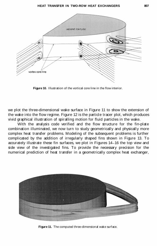
In order to clearly depict the three-dimensional vortical flow structure, we
plot flow lines at different cutting planes. As shown in Figure 10, critical pointsfound at different cutting planes are integrated to form the so-called vortical core

T. W. H. SHEU ET AL.806
Figure 8. Limiting streamlines on the fin as well as on the tube surface.
Figure 9. Illustration of lines of separation and reattachment for flows over the
vertical tube.
line. The spiraling flow is found to prevail in the vicinity of the vortical core line.
The spiral flow motion enhances the transfer of heat but causes the pressure drop
to increase in the recirculation region, and thus more power must be consumed. It
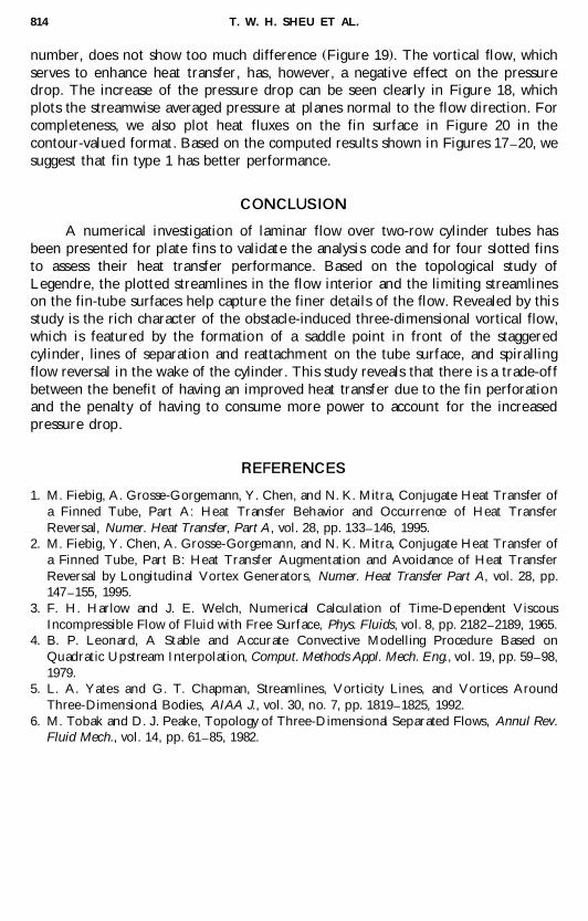
is also important to note that the size of the wake region determines the extent ofheat transfer deterioration and the increase of the pressure drop. For this reason,
HEAT TRANSFER IN TWO-ROW HEAT EXCHANGERS 807
Figure 10. Illustration of the vortical core line in the flow interior.
we plot the three-dimensional wake surface in Figure 11 to show the extension of
the wake into the flow regime. Figure 12 is the particle tracer plot, which produces
vivid graphical illustration of spiralling motion for fluid particles in the wake.
With the analysis code verified and the flow structure for the fin-plate
combination illuminated, we now turn to study geometrically and physically more
complex heat transfer problems. Modeling of the subsequent problems is further
complicated by the addition of irregularly shaped fins shown in Figure 13. Toaccurately illustrate these fin surfaces, we plot in Figures 14 ] 16 the top view and
side view of the investigated fins. To provide the necessary precision for the
numerical prediction of heat transfer in a geometrically complex heat exchanger,
Figure 11. The computed three-dimensional wake surface.

T. W. H. SHEU ET AL.808
Figure 12. Illustration of the spiralling flow motion in the wake behind the cylinder tube.
s . s . s .Figure 13. Schematic configurations of investigated fins: a slit type, b wavy type, c fin type 1, ands .d fin type 2.

HEAT TRANSFER IN TWO-ROW HEAT EXCHANGERS 809
Figure 14. Top and side views of the investigated slit-type heat exchanger.
Figure 15. Top and side views of the investigated wavy-type heat exchanger.

T. W. H. SHEU ET AL.810
Figure 16. Top and side views of the other two investigated fins.
Figure 17. Span-averaged heat transfer in the streamwise direction for five investigated fin
surfaces.

HEAT TRANSFER IN TWO-ROW HEAT EXCHANGERS 811
Figure 18. Averaged pressure distribution in the streamwise direction for five investigated fin
surfaces.
Figure 19. Span-averaged Nusselt numbers in the streamline direction as a function of
Reynolds numbers for the plate fin under investigation.

T. W. H. SHEU ET AL.812
Figure 20. Contour plots of heat flux q on different fin surfaces of heat exchanger.Ç
nonuniform grids were invoked. The grid resolution is 142 = 84 = 54 with D x smin
0.25 mm, D y s 0.25 mm, and D z s 0.014375 mm. According to the obtainedmin min
heat transfer capability, as shown in Figure 17, and the pressure drop, as shown in
Figure 18, we are led to conclude that all the fins have increased heat transfer. Fin
perforation also serves as a factor, aiding vortical flow formation, which can also

HEAT TRANSFER IN TWO-ROW HEAT EXCHANGERS 813
s .Figure 20. Contour plots of heat flux q on different fin surfaces of heat exchanger Continued .Ç
enhance heat transfer between the fin surface and the surrounding airflow. As a
result, it is clearly seen from Figure 17 that heat exchangers with slotted-finsurfaces outperform heat exchangers with plain surfaces. Among the slotted fins,
heat transfer performance, as measured in terms of the span-averaged Nusselt
T. W. H. SHEU ET AL.814
s .number, does not show too much difference Figure 19 . The vortical flow, which
serves to enhance heat transfer, has, however, a negative effect on the pressuredrop. The increase of the pressure drop can be seen clearly in Figure 18, which
plots the streamwise averaged pressure at planes normal to the flow direction. For
completeness, we also plot heat fluxes on the fin surface in Figure 20 in the
contour-value d format. Based on the computed results shown in Figures 17 ] 20, we
suggest that fin type 1 has better performance.
CONCLUSION
A numerical investigation of laminar flow over two-row cylinder tubes has
been presented for plate fins to validate the analysis code and for four slotted fins
to assess their heat transfer performance . Based on the topological study of
Legendre, the plotted streamlines in the flow interior and the limiting streamlineson the fin-tube surfaces help capture the finer details of the flow. Revealed by this
study is the rich character of the obstacle-induced three-dimensional vortical flow,
which is featured by the formation of a saddle point in front of the staggered
cylinder, lines of separation and reattachment on the tube surface, and spiralling
flow reversal in the wake of the cylinder. This study reveals that there is a trade-off
between the benefit of having an improved heat transfer due to the fin perforationand the penalty of having to consume more power to account for the increased
pressure drop.
REFERENCES
1. M. Fiebig, A. Grosse-Gorgemann, Y. Chen, and N. K. Mitra, Conjugate Heat Transfer of
a Finned Tube, Part A: Heat Transfer Behavior and Occurrence of Heat Transfer
Reversal, Numer. Heat Transfer, Part A, vol. 28, pp. 133 ] 146, 1995.
2. M. Fiebig, Y. Chen, A. Grosse-Gorgemann, and N. K. Mitra, Conjugate Heat Transfer of
a Finned Tube, Part B: Heat Transfer Augmentation and Avoidance of Heat Transfer
Reversal by Longitudinal Vortex Generators, Numer. Heat Transfer Part A, vol. 28, pp.
147 ] 155, 1995.
3. F. H. Harlow and J. E. Welch, Numerical Calculation of Time-Dependent Viscous
Incompressible Flow of Fluid with Free Surface, Phys. Fluids, vol. 8, pp. 2182 ] 2189, 1965.
4. B. P. Leonard, A Stable and Accurate Convective Modelling Procedure Based on
Quadratic Upstream Interpolation, Comput. Methods Appl. Mech. Eng., vol. 19, pp. 59 ] 98,
1979.
5. L. A. Yates and G. T. Chapman, Streamlines, Vorticity Lines, and Vortices Around
Three-Dimensional Bodies, AIAA J., vol. 30, no. 7, pp. 1819 ] 1825, 1992.
6. M. Tobak and D. J. Peake, Topology of Three-Dimensional Separated Flows, Annul Rev.
Fluid Mech., vol. 14, pp. 61 ] 85, 1982.