toner dcm4-700 series digital settop converte - toner cable
TRANSCRIPT
DCM4-700V
HD Set-Top Box User Guide
1. DCM4-700V 1.1 Front Panel 1.2 Rear Panel 1.3 Remote Control 2. Installation 3. Getting Started With DCM4-700V 4. Main Menu 4.1 Main Menu 4.2 Program List 4.3 AV Settings/ Video Output 4.4 HD Output/ SD Output 4.5 Smart Card 4.6 Settings 4.7 Language/ Change PIN 4.8 Time Zone 4.9 System Reset
Table Of Contents
5. Important Information
6. FCC 7. Troubleshooting
1.DCM4-700V
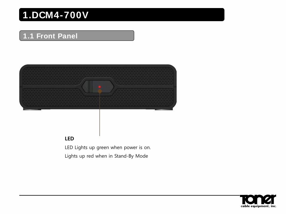
1.1 Front Panel
LED
LED Lights up green when power is on.
Lights up red when in Stand-By Mode
1.DCM4-700V
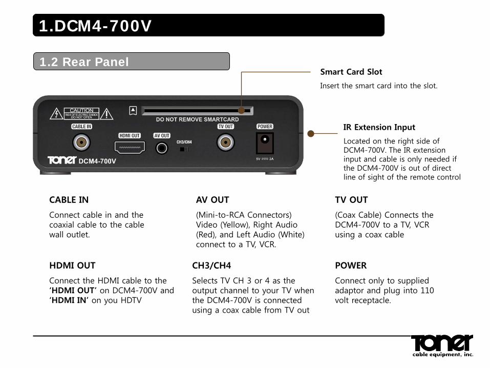
1.2 Rear Panel Smart Card Slot
Insert the smart card into the slot.
CABLE IN
Connect cable in and the coaxial cable to the cable wall outlet.
HDMI OUT
Connect the HDMI cable to the ‘HDMI OUT’ on DCM4-700V and ‘HDMI IN’ on you HDTV
AV OUT
(Mini-to-RCA Connectors) Video (Yellow), Right Audio (Red), and Left Audio (White) connect to a TV, VCR.
CH3/CH4
Selects TV CH 3 or 4 as the output channel to your TV when the DCM4-700V is connected using a coax cable from TV out
TV OUT
(Coax Cable) Connects the DCM4-700V to a TV, VCR using a coax cable
POWER
Connect only to supplied adaptor and plug into 110 volt receptacle.
IR Extension Input
Located on the right side of DCM4-700V. The IR extension input and cable is only needed if the DCM4-700V is out of direct line of sight of the remote control
1.DCM4-700V
1.3 Remote Control
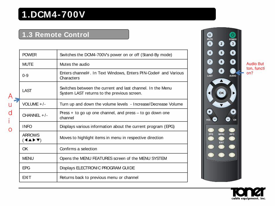
POWER Switches the DCM4-700V's power on or off (Stand-By mode)
MUTE Mutes the audio
0-9 Enters channel#. In Text Windows, Enters PIN-Code# and Various Characters
LAST Switches between the current and last channel. In the Menu System LAST returns to the previous screen.
VOLUME +/- Turn up and down the volume levels - Increase/Decrease Volume
CHANNEL +/- Press + to go up one channel, and press – to go down one channel
INFO Displays various information about the current program (EPG)
ARROWS (◀▲▶▼)
Moves to highlight items in menu in respective direction
OK Confirms a selection
MENU Opens the MENU FEATURES screen of the MENU SYSTEM
EPG Displays ELECTRONIC PROGRAM GUIDE
EXIT Returns back to previous menu or channel
Audio Button, function?
Audio
2.Installation
RCA Connection to TV
2.Installation
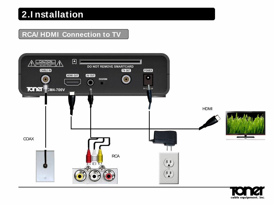
RCA/HDMI Connection to TV
HDMI
COAX
RCA
2.Installation
IR Remote Sensor Connection to TV
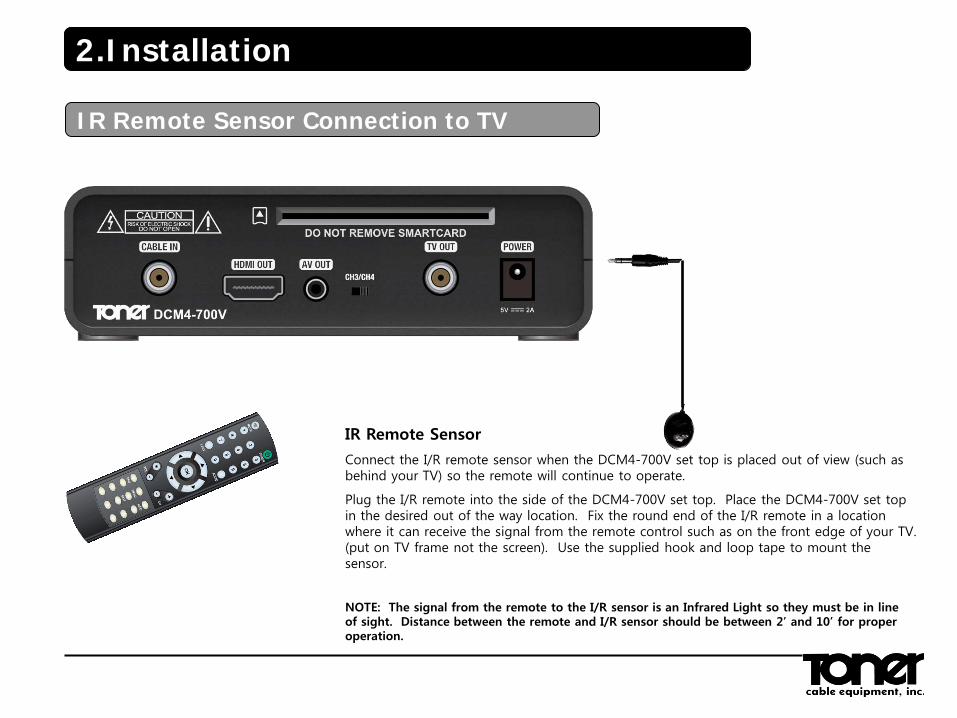
IR Remote Sensor
Connect the I/R remote sensor when the DCM4-700V set top is placed out of view (such as behind your TV) so the remote will continue to operate.
Plug the I/R remote into the side of the DCM4-700V set top. Place the DCM4-700V set top in the desired out of the way location. Fix the round end of the I/R remote in a location where it can receive the signal from the remote control such as on the front edge of your TV. (put on TV frame not the screen). Use the supplied hook and loop tape to mount the sensor.
NOTE: The signal from the remote to the I/R sensor is an Infrared Light so they must be in line of sight. Distance between the remote and I/R sensor should be between 2’ and 10’ for proper operation.
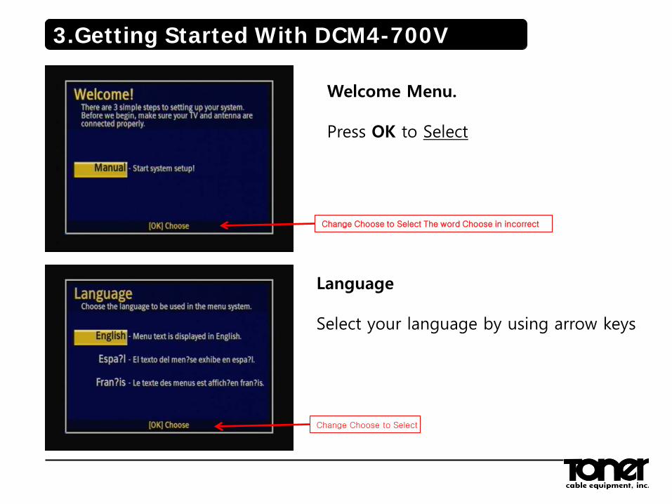
Welcome Menu. Press OK to Select
Language Select your language by using arrow keys
3.Getting Started With DCM4-700V
Change Choose to Select The word Choose in incorrect
Change Choose to Select
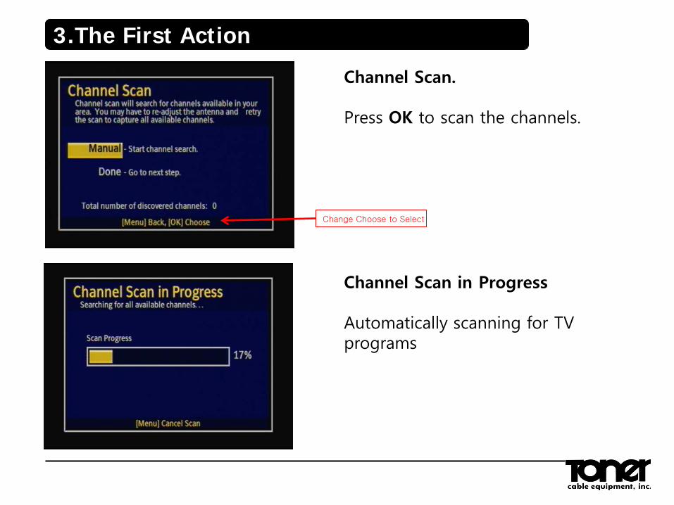
Channel Scan. Press OK to scan the channels.
Channel Scan in Progress Automatically scanning for TV programs
3.The First Action
Change Choose to Select
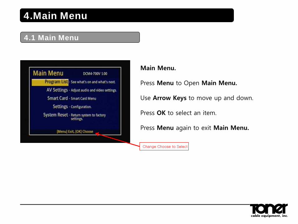
Main Menu. Press Menu to Open Main Menu. Use Arrow Keys to move up and down. Press OK to select an item. Press Menu again to exit Main Menu.
4.1 Main Menu
4.Main Menu
Change Choose to Select
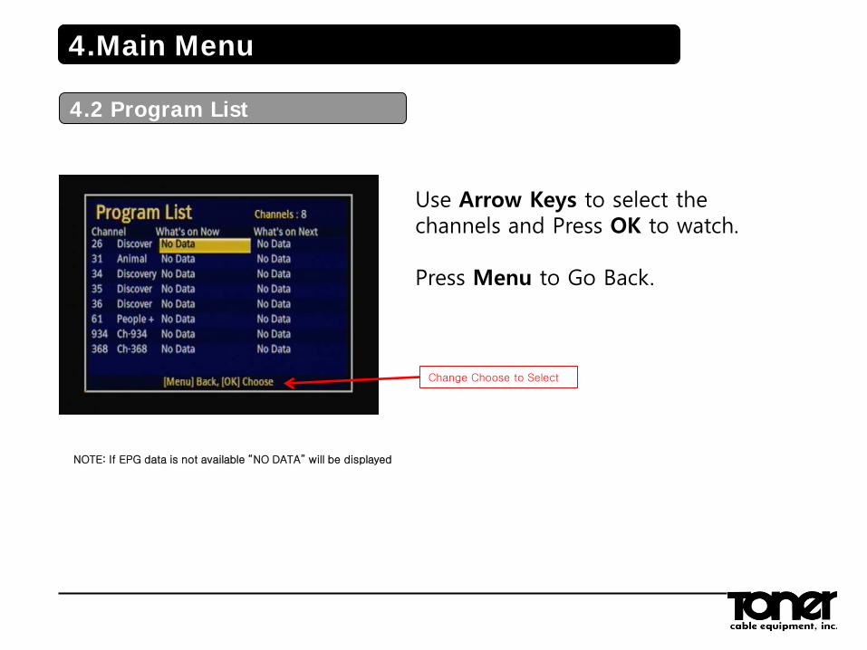
Use Arrow Keys to select the channels and Press OK to watch. Press Menu to Go Back.
4.2 Program List
4.Main Menu
NOTE: If EPG data is not available “NO DATA” will be displayed
Change Choose to Select
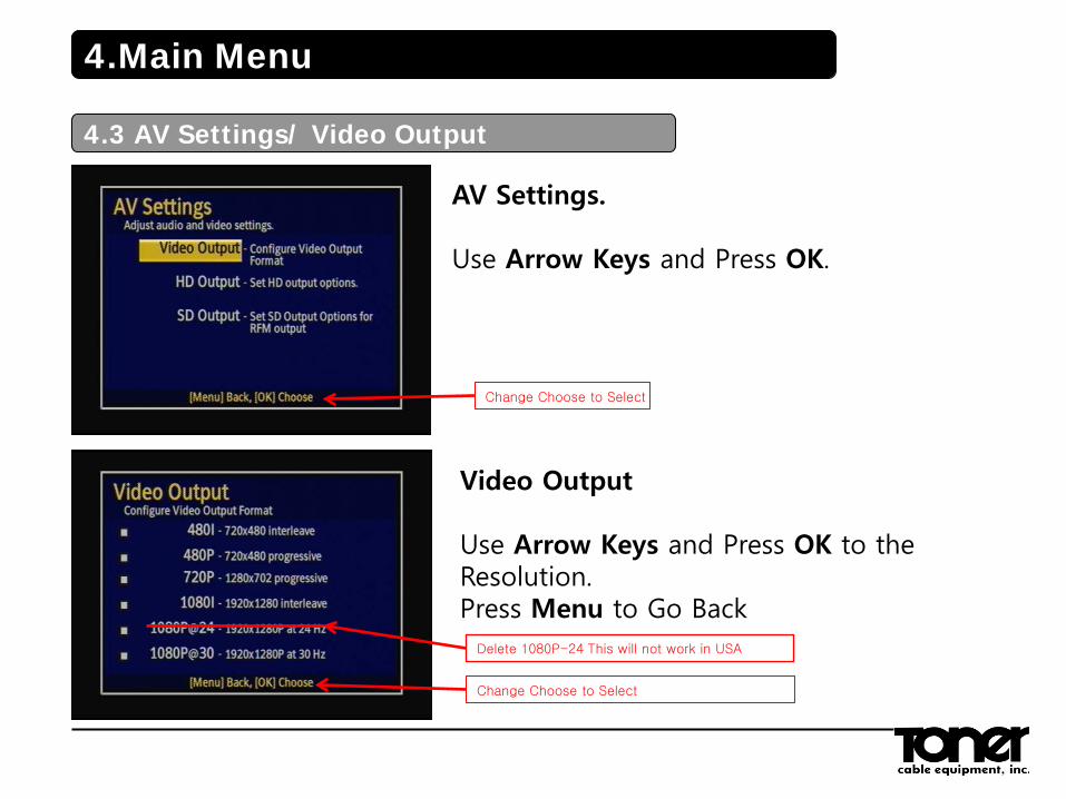
AV Settings. Use Arrow Keys and Press OK.
Video Output Use Arrow Keys and Press OK to the Resolution. Press Menu to Go Back
4.3 AV Settings/ Video Output
4.Main Menu
Change Choose to Select
Change Choose to Select
Delete 1080P-24 This will not work in USA
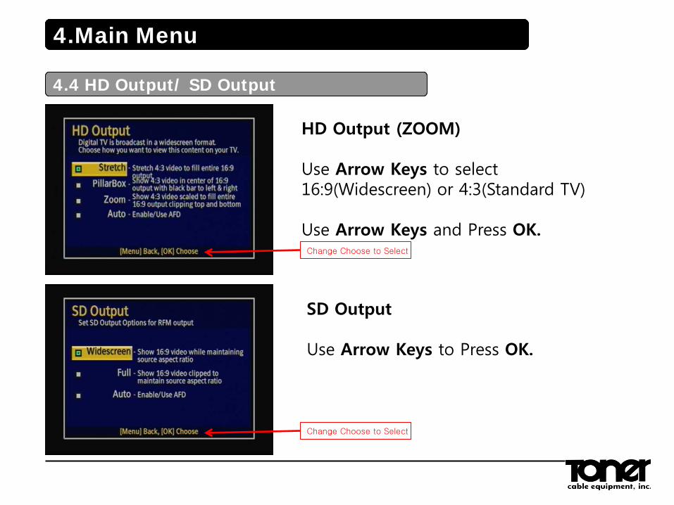
HD Output (ZOOM) Use Arrow Keys to select 16:9(Widescreen) or 4:3(Standard TV) Use Arrow Keys and Press OK.
SD Output Use Arrow Keys to Press OK.
4.Main Menu
4.3 HD Output/ SD Output
4.Main Menu
4.4 HD Output/ SD Output
Change Choose to Select
Change Choose to Select
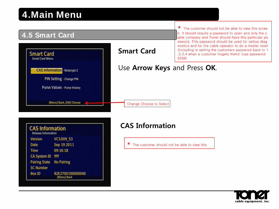
Smart Card Use Arrow Keys and Press OK.
CAS Information
4.Main Menu
4.4 Smart Card
4.Main Menu
4.5 Smart Card
* The customer should not be able to view this
* The customer should not be able to view this scree
n. It should require a password to open and only the cable company and Toner should have this particular password. This password should be used for settop diagnostics and for the cable operator to do a master reset (including re setting the customers password back to 1,2,3,4 when a customer forgets theirs! (use password 6358)
Change Choose to Select
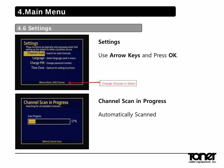
Settings Use Arrow Keys and Press OK.
Channel Scan in Progress Automatically Scanned
4.Main Menu
4.5 Settings
4.Main Menu
4.6 Settings
Change Choose to Select
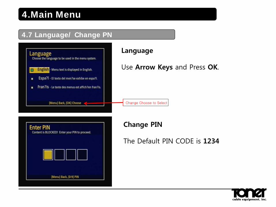
Language Use Arrow Keys and Press OK.
Change PIN The Default PIN CODE is 1234
4.Main Menu
4.7 Language/ Change PN
Change Choose to Select
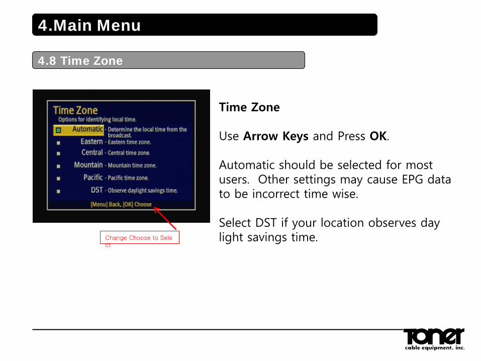
Time Zone Use Arrow Keys and Press OK. Automatic should be selected for most users. Other settings may cause EPG data to be incorrect time wise. Select DST if your location observes day light savings time.
4.Main Menu
4.8 Time Zone
Change Choose to Select
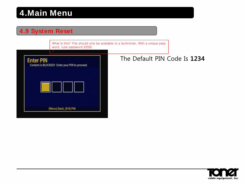
The Default PIN Code Is 1234
4.Main Menu
4.9 System Reset
What is this? This should only be available to a technician. With a unique password. (use password 6358) 3
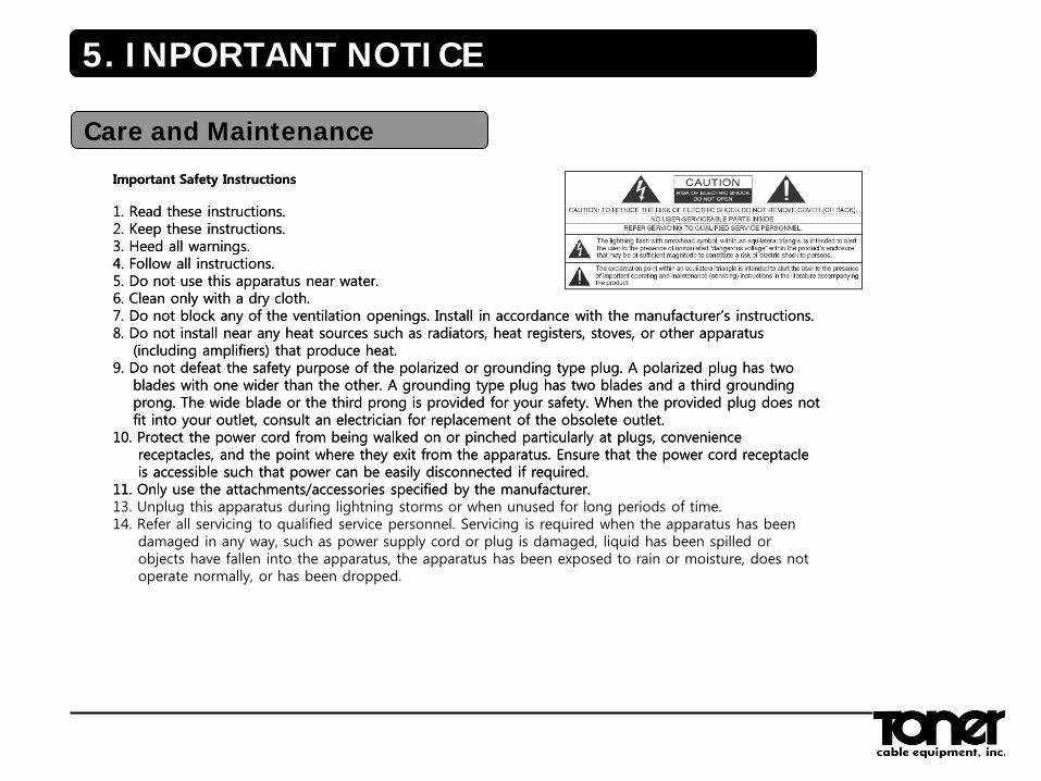
Important Safety Instructions 1. Read these instructions. 2. Keep these instructions. 3. Heed all warnings. 4. Follow all instructions. 5. Do not use this apparatus near water. 6. Clean only with a dry cloth. 7. Do not block any of the ventilation openings. Install in accordance with the manufacturer’s instructions. 8. Do not install near any heat sources such as radiators, heat registers, stoves, or other apparatus (including amplifiers) that produce heat. 9. Do not defeat the safety purpose of the polarized or grounding type plug. A polarized plug has two blades with one wider than the other. A grounding type plug has two blades and a third grounding prong. The wide blade or the third prong is provided for your safety. When the provided plug does not fit into your outlet, consult an electrician for replacement of the obsolete outlet. 10. Protect the power cord from being walked on or pinched particularly at plugs, convenience receptacles, and the point where they exit from the apparatus. Ensure that the power cord receptacle is accessible such that power can be easily disconnected if required. 11. Only use the attachments/accessories specified by the manufacturer. 13. Unplug this apparatus during lightning storms or when unused for long periods of time. 14. Refer all servicing to qualified service personnel. Servicing is required when the apparatus has been damaged in any way, such as power supply cord or plug is damaged, liquid has been spilled or objects have fallen into the apparatus, the apparatus has been exposed to rain or moisture, does not operate normally, or has been dropped.
5. INPORTANT NOTICE
Care and Maintenance
Important Safety Instructions 1. Read these instructions. 2. Keep these instructions. 3. Heed all warnings. 4. Follow all instructions. 5. Do not use this apparatus near water. 6. Clean only with a dry cloth. 7. Do not block any of the ventilation openings. Install in accordance with the manufacturer’s instructions. 8. Do not install near any heat sources such as radiators, heat registers, stoves, or other apparatus (including amplifiers) that produce heat. 9. Do not defeat the safety purpose of the polarized or grounding type plug. A polarized plug has two blades with one wider than the other. A grounding type plug has two blades and a third grounding prong. The wide blade or the third prong is provided for your safety. When the provided plug does not fit into your outlet, consult an electrician for replacement of the obsolete outlet. 10. Protect the power cord from being walked on or pinched particularly at plugs, convenience receptacles, and the point where they exit from the apparatus. Ensure that the power cord receptacle is accessible such that power can be easily disconnected if required. 11. Only use the attachments/accessories specified by the manufacturer.
This equipment has been tested and found to comply with the limits for a Class B digital device, pursuant to Part 15 of the FCC Rules. These limits are designed to provide reasonable protection against harmful interference in a residential installation. This equipment generates, uses and can radiate radio frequency energy and, if not installed and used in accordance with the instructions, may cause harmful interference to radio communications. However, there is no guarantee that interference will not occur in a particular installation. If this equipment does cause harmful interference to radio or television reception which can be determined by turning the equipment off and on, the user is encouraged to try to correct the interference by one or more of the following measures: • Increase the separation between the equipment and receiver. • Connect the equipment into an outlet on a circuit different from that to which the receiver is connected. • Consult the dealer or an experienced radio/TV technician for help. • Only shielded interface cable should be used. Finally, any changes or modifications to the equipment by the user not expressly approved by the grantee or manufacturer could void the user’s authority to operate such equipment.
6.FCC
FCC Information
6.FCC
FCC Information
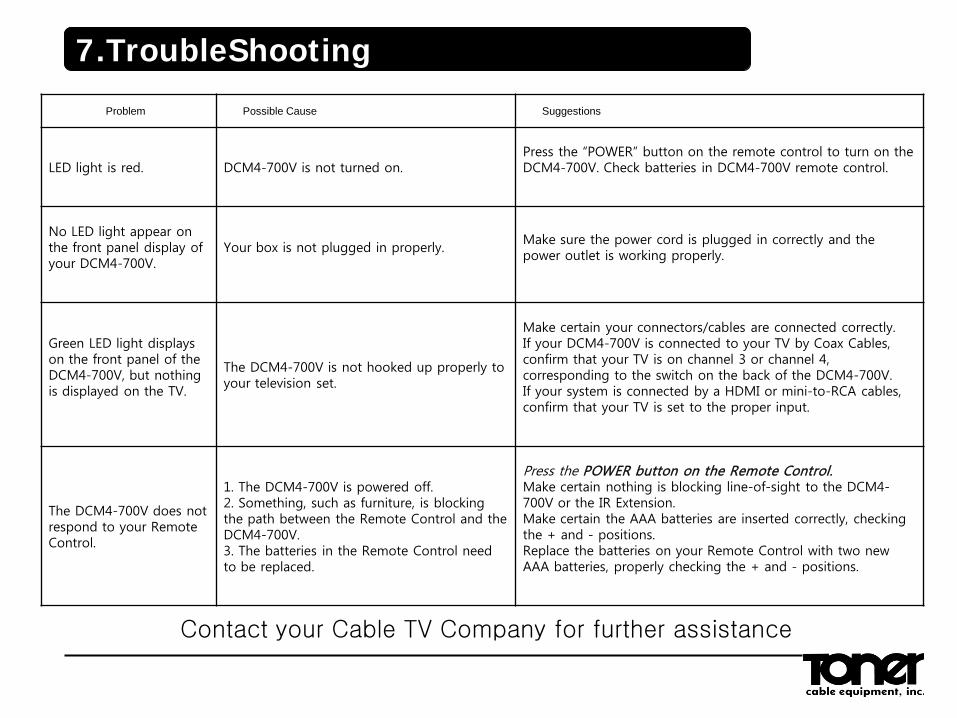
Problem Possible Cause Suggestions
LED light is red.
DCM4-700V is not turned on.
Press the “POWER” button on the remote control to turn on the DCM4-700V. Check batteries in DCM4-700V remote control.
No LED light appear on the front panel display of your DCM4-700V.
Your box is not plugged in properly.
Make sure the power cord is plugged in correctly and the power outlet is working properly.
Green LED light displays on the front panel of the DCM4-700V, but nothing is displayed on the TV.
The DCM4-700V is not hooked up properly to your television set.
Make certain your connectors/cables are connected correctly. If your DCM4-700V is connected to your TV by Coax Cables, confirm that your TV is on channel 3 or channel 4, corresponding to the switch on the back of the DCM4-700V. If your system is connected by a HDMI or mini-to-RCA cables, confirm that your TV is set to the proper input.
The DCM4-700V does not respond to your Remote Control.
1. The DCM4-700V is powered off. 2. Something, such as furniture, is blocking the path between the Remote Control and the DCM4-700V. 3. The batteries in the Remote Control need to be replaced.
Press the POWER button on the Remote Control. Make certain nothing is blocking line-of-sight to the DCM4-700V or the IR Extension. Make certain the AAA batteries are inserted correctly, checking the + and - positions. Replace the batteries on your Remote Control with two new AAA batteries, properly checking the + and - positions.
7.TroubleShooting
Contact your Cable TV Company for further assistance