tolerating memory latency through push prefetching …alvy/papers/taco.pdftolerating memory latency...
TRANSCRIPT
Tolerating Memory Latency through PushPrefetching for Pointer-Intensive Applications
CHIA-LIN YANG
National Taiwan University
and
ALVIN R. LEBECK
Duke University
and
HUNG-WEI TSENG and CHIEN-HAO LEE
National Taiwan University
Prefetching is often used to overlap memory latency with computation for array-based appli-cations. However, prefetching for pointer-intensive applications remains a challenge because ofthe irregular memory access pattern and pointer-chasing problem. In this paper, we proposed acooperative hardware/software prefetching framework, the push architecture, which is designedspecifically for linked data structures. The push architecture exploits program structure for futureaddress generation instead of relying on past address history. It identifies the load instructionsthat traverse a LDS and uses a prefetch engine to execute them ahead of the CPU execution.This allows the prefetch engine to successfully generate future addresses. To overcome the serialnature of LDS address generation, the push architecture employs a novel data movement model.It attaches the prefetch engine to each level of the memory hierarchy and pushes, rather thanpulls, data to the CPU. This push model decouples the pointer dereference from the transfer ofthe current node up to the processor. Thus a series of pointer dereferences becomes a pipelinedprocess rather than a serial process. Simulation results show that the push architecture can re-duce up to 100% of memory stall time on a suite of pointer-intensive applications, reducing overallexecution time by an average 15%.
Categories and Subject Descriptors: Memory Structures [Design Styles]: Cache memories
General Terms: Design,Experimentation,Performance
Additional Key Words and Phrases: Prefetch, Linked Data Structures, Pointer-Chasing, MemoryHierarchy
This research was supported in part by the ROC NSC Grant NSC-93-2752-E-002-008-PAE,DARPA Grant DABT63-98-1-0001, NSF Grants CDA-97-2637, CDA-95-12356, and EIA-99-72879,Duke University, Intel Corporation through a Ph.D. Fellowship and the T4E 2000 program.Author’s addresses: C.-L. Yang, H.-W. Tseng and C.-H. Lee, Department of Computer Scienceand Information Engineering, National Taiwan University. No. 1, Sec. 4, Roosevelt Rd., Taipei,Taiwan, R.O.C.; Alvin R. Lebeck, Department of Computer Science, Duke University, Durham,NC 27708Permission to make digital/hard copy of all or part of this material without fee for personalor classroom use provided that the copies are not made or distributed for profit or commercialadvantage, the ACM copyright/server notice, the title of the publication, and its date appear, andnotice is given that copying is by permission of the ACM, Inc. To copy otherwise, to republish,to post on servers, or to redistribute to lists requires prior specific permission and/or a fee.c© 2004 ACM 0164-0925/2004/0500-0001 $5.00
ACM Transactions on Architecture and Code Optimization, Vol. V, No. N, October 2004, Pages 1–0??.
2 · C. Yang et al.
1. INTRODUCTION
Since 1980, microprocessor performance has improved 60% per year, however, mem-ory access time has improved only 10% per year. As the performance gap betweenprocessors and memory continues to grow, techniques to reduce the effect of thisdisparity are essential to build a high performance computer system. The use ofcaches between the CPU and main memory is recognized as an effective methodto bridge this gap. If programs exhibit good temporal and spatial locality, themajority of memory requests can be satisfied by caches without having to accessmain memory. However, a cache’s effectiveness can be limited for programs withpoor locality.
Prefetching is a common technique that attempts to hide memory latency byissuing memory requests earlier than demand fetching a cache block when a missoccurs. Prefetching works very well for programs with regular access patterns. Un-fortunately, many applications create sophisticated data structures using pointers,and do not exhibit sufficient regularity for conventional prefetch techniques to ex-ploit. Furthermore, prefetching pointer-intensive data structures can be limited bythe serial nature of pointer dereferences—known as the pointer chasing problem—since the address of the next node is not known until the contents of the currentnode is accessible.
For these applications, performance may improve if lower levels of the memoryhierarchy could derefence pointers and proactively push data up to the processorrather than requiring the processor to fetch each node before initating the nextrequest. An oracle could accomplish this by knowing the layout and traversal orderof the pointer-based data structure, and thus overlap the transfer of consecutivelyaccessed nodes up the memory hierarchy. The challenge is to develop a realizablememory hierarchy that can obtain these benefits.
This paper presents a novel memory architecture to perform pointer dereferencesin the lower levels of the memory hierarchy and push data up to the CPU. In thisarchitecture, if the cache block containing the data corresponding to pointer p (*p)is found at a particular level of the memory hierarchy, the request for the nextelement (*p+offset) is issued from that level. This allows the access for the nextnode to overlap with the transfer of the previous element. In this way, a series ofpointer dereferences becomes a pipelined process rather than a serial process.
The push architecture is a cooperative software/hardware prefetching frameworkthat supports the above push model. The push architecture identifies instructionsthat traverse LDS (LDS traversal kernels) statically and uses a micro-controllerto execute traversal kernels only. This micro-controller is called a prefetch engine(PFE). A PFE can successfully generate future addresses when it runs ahead of theCPU. To realize the push model, the push architecture attaches a PFE to each levelof the memory hierarchy. These PFEs at different levels of the memory hierarchyexecute LDS traversal kernels cooperatively. Cache blocks accessed by the PFEsat the L2 and memory levels are pro-actively pushed up to the CPU. In our earlierwork [Yang and Lebeck 2000], the PFE is a specialized engine which only supportslinked-list traversal. In this paper, the PFE is a programmable processor which cansupport a multitude of LDS traversal kernels. In addition, we address three maindesign issues in implementing the proposed push architecture:ACM Transactions on Architecture and Code Optimization, Vol. V, No. N, October 2004.
Tolerating Memory Latency through Push Prefetching for Pointer-Intensive Applications · 3
(1) Interaction among PFEsThe PFEs at different levels of the memory hierarchy work cooperatively toperform the prefetching task. Therefore, the push architecture needs to specifyhow they interact with one another. In this paper, we establish a generalinteraction scheme among three PFEs, particularly how a PFE suspends andresumes execution and when the lower level PFEs should be activated.
(2) Reducing the effect of redundant prefetchesOne potential problem of the push model is that the cache blocks pushed upby the lower level PFEs could already exist in the upper level. These are calledredundant prefetches. Redundant prefetches can impact performance by wast-ing bus bandwidth or causing the PFE to run behind the main computation.To reduce the effect of redundant prefetches, the push architecture uses smalldata caches in the L2 and memory PFEs to capture recently accessed cacheblocks.
(3) Synchronization between the processor and PFEsTiming is an important factor for the success of a prefetching scheme. Prefetch-ing too late results in useless prefetches; prefetching too early can cause cachepollution. In this paper, we present a throttle mechanism to control the prefetchdistance according to a program’s runtime behavior. The PFEs aggressivelyissue prefetch requests and suspend execution when the CPU is not able tokeep up with the prefetching thread.
Simulation results show that the push model proposed in this paper is very effec-tive at reducing the impact of the pointer-chasing problem on prefetching perfor-mance. For applications that have little computation between node accesses, thepush architecture reduces execution time by 13% to 23% (using a single-issue, in-order programmable PFE), while the traditional pull method is not able to achieveany speedup. Increasing the issue width of the programmable PFE can furtherimprove performance. With throttling, the push model can achieve performancecomparable to a perfect memory system when there is enough computation be-tween node accesses. Simulation results also show that adding a small data cachein the L2 and memory PFEs yields between 4% to 25% performance improvementfor applications that experience a significant amount of redundant prefetches. Wealso examine if we can reduce the hardware cost of the push architecture by usingfewer PFEs. Simulation results show that the push architecture using the PFEonly at the L1 and main memory levels can achieve performance close to the oneattaching the PFE to each level of the memory hierarchy. If the CPU is a multi-threading processor, we can further reduce the hardware cost by invoking a helperthread to execute the LDS traversal kernel instead of using a PFE at the L1 level.We also compare the push architecture against jump-pointer prefetching [Roth andSohi 1999], which is a pull-based prefetching mechanism but overcomes the pointer-chasing problem by providing additional pointers to connect non-adjacent nodes.Ideally, jump-pointer prefetching can tolerate any amount of memory latency aslong as the jump-pointer interval is set appropriately. However, due to the lim-itations imposed by jump-pointer creation, jump-pointer prefetching shows littleperformance advantage or even adverse effects on some applications studied in thispaper. Therefore, the push architecture outperforms jump-pointer prefetching for
ACM Transactions on Architecture and Code Optimization, Vol. V, No. N, October 2004.

4 · C. Yang et al.
list = head; while (list)while (list) {{
p = list->patient; p = list->patient; data = p->data; data = p->data; process(data); list = list->next; list = list ->next ;
} } (a) (b)
Fig. 1. Traversal Kernel
these applications. Simulation results show that the push architecture providescomparable average performance with jump-pointer prefetching.
The rest of this paper is organized as follows. Section 2 presents the high leveloverview of the push architecture. The implementation details are addressed inSection 3. Section 4 presents our simulation results. Related work is discussed inSection 5. We conclude in Section 6.
2. THE PUSH ARCHITECTURE
The push architecture is a cooperative software/hardware prefetching frameworkdesigned specifically for linked data structures. Prefetching linked data structures ischallenging because of address irregularity and the pointer-chasing problem. Thissection describes how the proposed push architecture overcomes these two chal-lenges.
2.1 LDS Traversal Kernels
Traditional prefetching schemes rely on the regularity of the address stream topredict future addresses. These schemes work well for array-based numeric appli-cations because the address stream presents arithmetic regularity. But they arenot effective for linked data structures (LDS), because elements are allocated dy-namically from the heap and adjacent elements are not necessarily contiguous inmemory. Although linear layout of an LDS may be achieved through careful dataplacement [?], the linearity property often disappears as the data structures evolve.
Instead of relying on address regularity, program structure can be used for futureaddress generation [Roth et al. 1998]. Consider the LDS traversal example of alist traversal shown in Figure 1(a). The first instruction (list=head) loads theroot address of the LDS list, while the three pointer loads form the body of thetraversal kernel (see Figure 1(b)). The first load—called a traversal load—traversesinternal links of the list. The second load—called a data load—accesses data otherthan memory addresses. The third load (list=list→next)—called a recurrent load—generates the address of the next element of the list structure.
By executing only the instructions in a traversal kernel, a prefetch engine couldrun ahead of the main computation, correctly generating future addresses. Roth etal. [Roth et al. 1998] propose identifying traversal kernels dynamically in hardware.Their method represents the traversal kernel as a collection of explicit data depen-dence relationships. Once a pointer load is resolved, all the loads that depend onit are issued. This might be efficient for list-based applications but not necessarilyACM Transactions on Architecture and Code Optimization, Vol. V, No. N, October 2004.

Tolerating Memory Latency through Push Prefetching for Pointer-Intensive Applications · 5
for tree traversals, because it prefetches all child nodes once the parent node isobtained. This may result in many early prefetches if the program traverses thetree in depth-first order.
In this work, we construct the LDS traversal kernel statically, so we can includeinformation on traversal order. Although we construct kernels by hand in thispaper, compiler or executable editor static analysis generally has larger analysisscope, and can consider traversal orders when constructing the kernels. However,there are cases when the traversal order or LDS access footprints (i.e., which fieldsof a LDS structure are accessed) cannot be determined statically.
In some cases runtime information is available prior to traversal kernel executionand can be incorporated into the traversal kernel, for example, a key value usedin searching a hash table. For access patterns with unpredictable traversal order,we can either aggressively prefetch all LDS elements or conservatively prefetchonly those guaranteed to be accessed. The key thing is that the PFE does notperform computation beyond simple value comparison for flow control. Similarly,for applications that dynamically change the data structure during traversal, we canconservatively limit the prefetch distance to a few LDS elements. This prevents thePFE from prefetching down the wrong path if the CPU has modified the structure.
To support these various access patterns, we simply create different traversal ker-nels. Some run until they encounter a NULL pointer, others can include runtimeinformation provided by the main CPU to determine which portion of a data struc-ture to prefetch. Finally, we can limit prefetch distances by setting loop iterationcounts or inlining a fixed number of instructions to control how many LDS elementsare prefetched.
2.2 The Push Model
The conventional data movement model initiates all memory requests (demandfetch or prefetch) by the processor or upper level of the memory hierarchy. Wecall it the pull model because cache blocks are moved up the memory hierarchy inresponse to requests issued from the upper levels. Since pointer dereferences arerequired to generate addresses for successive prefetch requests (recurrent loads),these techniques serialize the prefetch process.
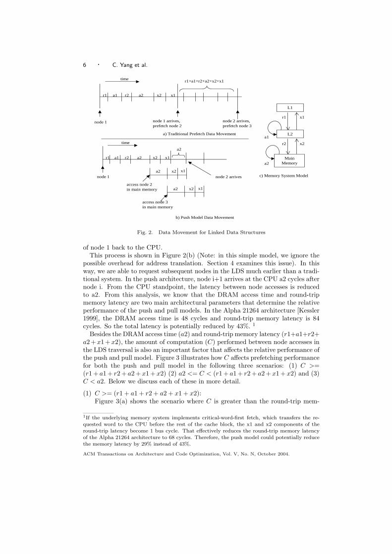
Consider the prefetch schedule shown in Figure 2(a), assuming each recurrentload is a L2 cache miss. The memory latency is divided into six parts (r1: sendinga request from L1 to L2; a1: L2 access; r2: sending a request from L2 to mainmemory; a2: memory access; x2: transferring a cache block back to L2; x1: trans-ferring a cache block back to L1). Using this timing, node i+1 arrives at the CPU(r1+a1+r2+a2+x2+x1) cycles (the round-trip memory latency) after node i.
In contrast, the push model performs pointer dereferences at the lower levels ofthe memory hierarchy by executing traversal kernels in micro-controllers associ-ated with each memory hierarchy level. The accessed cache blocks are pro-activelypushed up to the processor. This eliminates the request from the upper levels tothe lower level, and enables overlapping the data transfer of node i with the RAMaccess of node i+1. For example, assume that the request for node i accesses mainmemory at time t. The result is known to the memory controller at time t+a2,where a2 is the memory access latency. The controller then issues the request fornode 2 to main memory at time t+a2, thus overlapping this access with the transfer
ACM Transactions on Architecture and Code Optimization, Vol. V, No. N, October 2004.
6 · C. Yang et al.
node 1 node 1 arrives,prefetch node 2
node 2 arrives,prefetch node 3
r1 a1 a2r2 x2 x1
r1+a1+r2+a2+x2+x1time
a2 x2 x1
access node 2in main memory a2 x2 x1
access node 3in main memory
node 2 arrives
a2
node1
r1 a1 a2r2 x2 x1
time
a) Traditional Prefetch Data Movement
b) Push Model Data Movement
L1
r1
a1
x1
L2
r2 x2
a2Main
Memory
c) Memory System Model
Fig. 2. Data Movement for Linked Data Structures
of node 1 back to the CPU.This process is shown in Figure 2(b) (Note: in this simple model, we ignore the
possible overhead for address translation. Section 4 examines this issue). In thisway, we are able to request subsequent nodes in the LDS much earlier than a tradi-tional system. In the push architecture, node i+1 arrives at the CPU a2 cycles afternode i. From the CPU standpoint, the latency between node accesses is reducedto a2. From this analysis, we know that the DRAM access time and round-tripmemory latency are two main architectural parameters that determine the relativeperformance of the push and pull models. In the Alpha 21264 architecture [Kessler1999], the DRAM access time is 48 cycles and round-trip memory latency is 84cycles. So the total latency is potentially reduced by 43%. 1
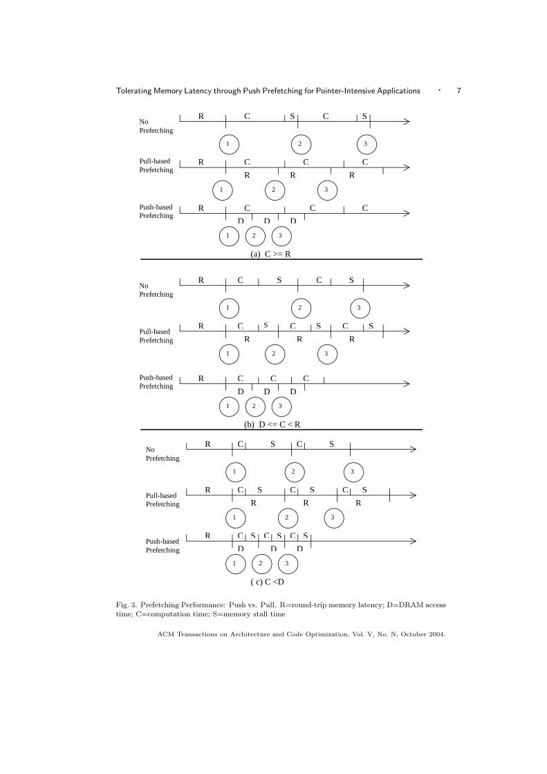
Besides the DRAM access time (a2) and round-trip memory latency (r1+a1+r2+a2+x1+x2), the amount of computation (C) performed between node accesses inthe LDS traversal is also an important factor that affects the relative performance ofthe push and pull model. Figure 3 illustrates how C affects prefetching performancefor both the push and pull model in the following three scenarios: (1) C >=(r1 + a1 + r2 + a2 + x1 + x2) (2) a2 <= C < (r1 + a1 + r2 + a2 + x1 + x2) and (3)C < a2. Below we discuss each of these in more detail.
(1) C >= (r1 + a1 + r2 + a2 + x1 + x2):Figure 3(a) shows the scenario where C is greater than the round-trip mem-
1If the underlying memory system implements critical-word-first fetch, which transfers the re-quested word to the CPU before the rest of the cache block, the x1 and x2 components of theround-trip latency become 1 bus cycle. That effectively reduces the round-trip memory latencyof the Alpha 21264 architecture to 68 cycles. Therefore, the push model could potentially reducethe memory latency by 29% instead of 43%.
ACM Transactions on Architecture and Code Optimization, Vol. V, No. N, October 2004.
Tolerating Memory Latency through Push Prefetching for Pointer-Intensive Applications · 7
C S
1
C S
Pull-based Prefetching
No Prefetching
R
1
R
2
C
R
2
C
3
R
3
Push-based Prefetching
R C C
1
D D
2 3
D
(a) C >= R
C S
1
C S No Prefetching
R
2 3
C S
1
Pull-based Prefetching
R
2 3
R
C S
R
C S
R
Push-based Prefetching
R C
1
D D
2 3
D
C C
(b) D <= C < R
C S
1
C S No Prefetching
R
2 3
C S
1
Pull-based Prefetching
R
2 3
R
C S
R
C S
R
C S
1
Push-based Prefetching
R
2 3
D
C S
D
C S
D
( c) C <D
R
C
C
Fig. 3. Prefetching Performance: Push vs. Pull. R=round-trip memory latency; D=DRAM accesstime; C=computation time; S=memory stall time
ACM Transactions on Architecture and Code Optimization, Vol. V, No. N, October 2004.
8 · C. Yang et al.
Prefetch Buffer L1
L2
Main
Memory
prefetched blocks
prefetched blocks
Prefetch Engine
Prefetch Engine
Prefetch Engine
prefetch req
prefetch req
prefetch req
L2 Bus
Memory Bus
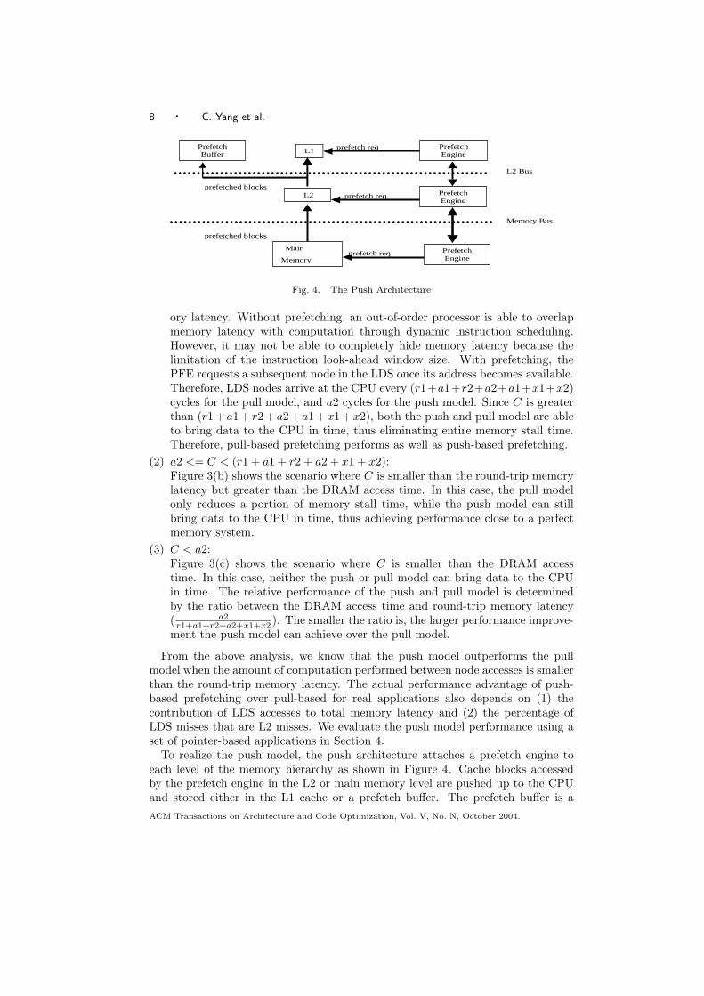
Fig. 4. The Push Architecture
ory latency. Without prefetching, an out-of-order processor is able to overlapmemory latency with computation through dynamic instruction scheduling.However, it may not be able to completely hide memory latency because thelimitation of the instruction look-ahead window size. With prefetching, thePFE requests a subsequent node in the LDS once its address becomes available.Therefore, LDS nodes arrive at the CPU every (r1+a1+r2+a2+a1+x1+x2)cycles for the pull model, and a2 cycles for the push model. Since C is greaterthan (r1 + a1 + r2 + a2 + a1 + x1 + x2), both the push and pull model are ableto bring data to the CPU in time, thus eliminating entire memory stall time.Therefore, pull-based prefetching performs as well as push-based prefetching.
(2) a2 <= C < (r1 + a1 + r2 + a2 + x1 + x2):Figure 3(b) shows the scenario where C is smaller than the round-trip memorylatency but greater than the DRAM access time. In this case, the pull modelonly reduces a portion of memory stall time, while the push model can stillbring data to the CPU in time, thus achieving performance close to a perfectmemory system.
(3) C < a2:Figure 3(c) shows the scenario where C is smaller than the DRAM accesstime. In this case, neither the push or pull model can bring data to the CPUin time. The relative performance of the push and pull model is determinedby the ratio between the DRAM access time and round-trip memory latency( a2
r1+a1+r2+a2+x1+x2 ). The smaller the ratio is, the larger performance improve-ment the push model can achieve over the pull model.
From the above analysis, we know that the push model outperforms the pullmodel when the amount of computation performed between node accesses is smallerthan the round-trip memory latency. The actual performance advantage of push-based prefetching over pull-based for real applications also depends on (1) thecontribution of LDS accesses to total memory latency and (2) the percentage ofLDS misses that are L2 misses. We evaluate the push model performance using aset of pointer-based applications in Section 4.
To realize the push model, the push architecture attaches a prefetch engine toeach level of the memory hierarchy as shown in Figure 4. Cache blocks accessedby the prefetch engine in the L2 or main memory level are pushed up to the CPUand stored either in the L1 cache or a prefetch buffer. The prefetch buffer is aACM Transactions on Architecture and Code Optimization, Vol. V, No. N, October 2004.
Tolerating Memory Latency through Push Prefetching for Pointer-Intensive Applications · 9
small, fully-associative cache, which can be accessed in parallel with the L1 cache.In the next section, we present the implementation details of the push architec-ture, including the architecture of the PFE, the interaction scheme among thePFEs, mechanisms to avoid early and redundant prefetches and modifications tothe cache/memory controller to support the push model.
3. IMPLEMENTATIONS OF THE PUSH ARCHITECTURE
In this section, we describe the implementation details of the push architecture.Section 3.1 describes the architecture of the prefetch engine. Section 3.2 explainshow the PFEs at different levels of the memory hierarchy interact with one another.Then, we present a mechanism to synchronize the CPU and PFE execution inSection 3.3. The push model also places new demands on the memory hierarchy.Section 3.4 addresses this issue. In Section 3.5, we present two variations of the pusharchitecture. Finally, we discuss the issues on supporting the push architecture inthe multiprogramming and multiprocessor systems in Section 3.6.
3.1 PFE Design
The task of the PFE is to execute the traversal kernel. It does not perform massivecomputation except for calculating addresses and value comparison for control flow.Therefore, the PFE does not need to have the full computation capabilities of ageneral purpose processor, such as multiply, division and floating-point operations.However, to execute different traversal patterns, the engine needs the ability todecode a sequence of instructions. We implement the prefetch engine as a 5 stagepipeline, in-order single issue processor. The processor pipeline stages are: 1)Fetch: fetch instructions from the program instruction stream, 2) Decode: decodeinstructions, 3) Execute: execute ready instructions if the required functional unitsare available, 4) Memory: issue request to the memory system, and 5) Writeback:write results to the register file.
The PFE supports three types of load instructions. They are ld recurrent, ld dataand ld local. Ld recurrent and ld data are used for recurrent and data loads, re-spectively. The use of ld recurrent is explained in the next section. The ld datainstruction is a non-binding load similar to the existing prefetch instructions. It isused for loads that do not have dependent instructions. The third kind is ld local,which is used to access local memory inside an engine. The local memory serves asa stack for recursive traversal kernels and can be accessed in one cycle. The size ofthe stack needed is proportional to the height of a tree. Thus, the maximum stacksize for a 32-level tree is 4K, assuming all registers (32 registers) are modified inthe program. So one cycle access time is feasible.
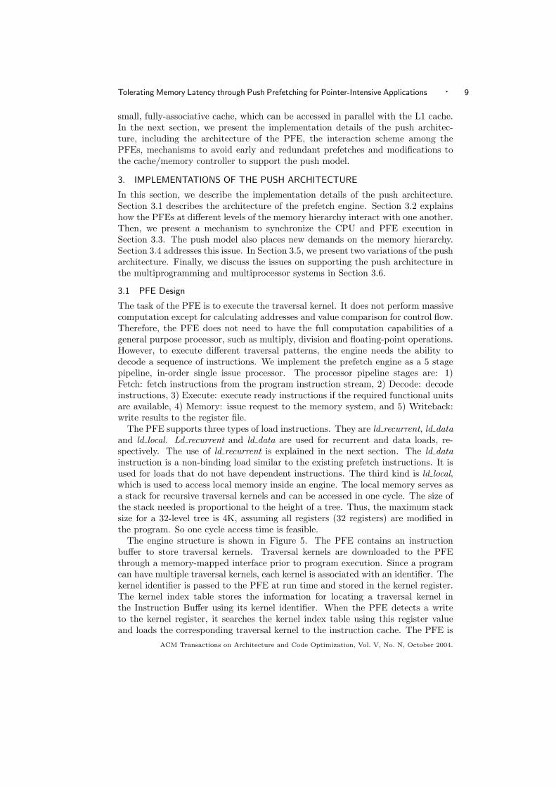
The engine structure is shown in Figure 5. The PFE contains an instructionbuffer to store traversal kernels. Traversal kernels are downloaded to the PFEthrough a memory-mapped interface prior to program execution. Since a programcan have multiple traversal kernels, each kernel is associated with an identifier. Thekernel identifier is passed to the PFE at run time and stored in the kernel register.The kernel index table stores the information for locating a traversal kernel inthe Instruction Buffer using its kernel identifier. When the PFE detects a writeto the kernel register, it searches the kernel index table using this register valueand loads the corresponding traversal kernel to the instruction cache. The PFE is
ACM Transactions on Architecture and Code Optimization, Vol. V, No. N, October 2004.
10 · C. Yang et al.
Instruction Cache
Processor
TLB
Cache/M emory
Stack local access
non-local access
Root Register Register File
PFE Data Cache
hit
miss
Instruction Buffer
Kernel Index Table
Kernel Register
Fig. 5. The Prefetch Engine
activated when the root address of the LDS being traversed is written into the rootregister. The traversal kernel may need other run time information in addition tothe root address, such as a key value used in searching a hash table. So a portionof PFE registers are memory-mapped to allow the CPU to convey other run timeinformation down the PFE if necessary.
The PFE contains a TLB for address translation for non-local loads because thecache/memory is indexed using physical addresses. We assume hardware-managedTLB. TLBs at different levels of the memory hierarchy are updated independently.The L2 and memory PFE contains a local data cache to reduce the performanceimpact of redundant prefetches, which push up cache blocks that already exist inthe upper level of memory hierarchy. Redundant prefetches could cause the PFEsto run behind of the main execution because memory accesses are satisfied moreslowly in the lower levels of the memory hierarchy. This is particularly importantfor applications with small amounts of locality, such as depth-first tree traversal.When the execution moves up the tree, all the parent nodes are revisited. For nodesclose to the leaves, the second access could be a cache hit and become a redundantprefetch. Therefore, we use a data cache in the L2 and memory PFE to capturethis locality. Only memory requests that miss in the local data cache are sent tothe cache/memory controller. In this way, we can avoid issuing prefetches for thosecache blocks that have been pushed up to the upper level of the memory hierarchydue to earlier prefetches. Therefore, the size of the local data cache should be thesame as the size of the push buffer at the L1 level.
3.2 Interaction Among Prefetch Engines
The PFEs need two pieces of information to start execution: the root address andthe kernel identifier. These values are communicated to the engines through storeoperations to memory-mapped registers of the PFEs. The root address is onlywritten to the L1 engine, which then triggers the L1 PFE.
The idea behind the push model is to perform pointer dereferences at the levelwhere the LDS element resides such that the cache blocks can arrive at the CPUearlier than a pull-based prefetch. Since a recurrent load is responsible for loadingthe next node address, we use it as a hint for which memory level should performprefetching activity. The ld recurrent instruction is used to distinguish a recurrentload from other loads. When a recurrent load causes a L1 miss, the cache controllersignals the L1 PFE to stop execution. If this recurrent load is a hit in the L2 cache,ACM Transactions on Architecture and Code Optimization, Vol. V, No. N, October 2004.
Tolerating Memory Latency through Push Prefetching for Pointer-Intensive Applications · 11
00400950 addi u $sp[ 29] , $sp[ 29] , - 56 00400958 sw $r a[ 31] , 48( $sp[ 29] ) 00400960 sw $s8[ 30] , 44( $sp[ 29] ) 00400968 sw $s0[ 16] , 40( $sp[ 29] ) 00400970 addu $s8[ 30] , $zer o[ 0] , $sp[ 29] 00400978 addu $s0[ 16] , $zer o[ 0] , $a0[ 4] 00400980 beq $s0[ 16] , $zer o[ 0] , 004009a8(x)00400988 l w $a0[ 4] , 4( $s0[ 16] ) 00400990 j al 00400950 <K_Tr eeAdd>(y)00400998 l w $a0[ 4] , 8( $s0[ 16] ) 004009a0 j al 00400950 <K_Tr eeAdd> 004009a8 addu $sp[ 29] , $zer o[ 0] , $s8[ 30] 004009b0 l w $r a[ 31] , 48( $sp[ 29] ) 004009b8 l w $s8[ 30] , 44( $sp[ 29] ) 004009c0 l w $s0[ 16] , 40( $sp[ 29] ) 004009c8 addi u $sp[ 29] , $sp[ 29] , 56 004009d0 j r $r a[ 31]
1
2 5
3 4 6 7
x y
Recurrent Load PC Resume PC400988 400998400998 4009a8
(a) Traversal Kernel
(b) Data Structure
(c) Resume PC Table
Fig. 6. Tree Traversal
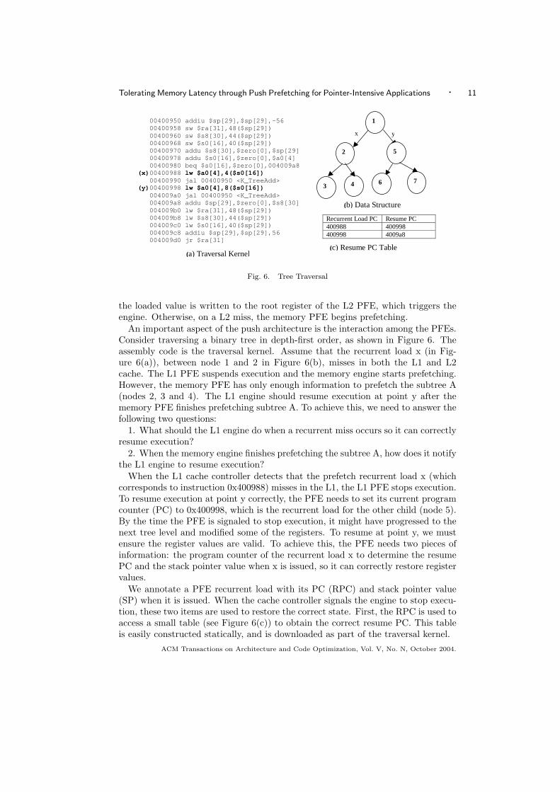
the loaded value is written to the root register of the L2 PFE, which triggers theengine. Otherwise, on a L2 miss, the memory PFE begins prefetching.
An important aspect of the push architecture is the interaction among the PFEs.Consider traversing a binary tree in depth-first order, as shown in Figure 6. Theassembly code is the traversal kernel. Assume that the recurrent load x (in Fig-ure 6(a)), between node 1 and 2 in Figure 6(b), misses in both the L1 and L2cache. The L1 PFE suspends execution and the memory engine starts prefetching.However, the memory PFE has only enough information to prefetch the subtree A(nodes 2, 3 and 4). The L1 engine should resume execution at point y after thememory PFE finishes prefetching subtree A. To achieve this, we need to answer thefollowing two questions:
1. What should the L1 engine do when a recurrent miss occurs so it can correctlyresume execution?
2. When the memory engine finishes prefetching the subtree A, how does it notifythe L1 engine to resume execution?
When the L1 cache controller detects that the prefetch recurrent load x (whichcorresponds to instruction 0x400988) misses in the L1, the L1 PFE stops execution.To resume execution at point y correctly, the PFE needs to set its current programcounter (PC) to 0x400998, which is the recurrent load for the other child (node 5).By the time the PFE is signaled to stop execution, it might have progressed to thenext tree level and modified some of the registers. To resume at point y, we mustensure the register values are valid. To achieve this, the PFE needs two pieces ofinformation: the program counter of the recurrent load x to determine the resumePC and the stack pointer value when x is issued, so it can correctly restore registervalues.
We annotate a PFE recurrent load with its PC (RPC) and stack pointer value(SP) when it is issued. When the cache controller signals the engine to stop execu-tion, these two items are used to restore the correct state. First, the RPC is used toaccess a small table (see Figure 6(c)) to obtain the correct resume PC. This tableis easily constructed statically, and is downloaded as part of the traversal kernel.
ACM Transactions on Architecture and Code Optimization, Vol. V, No. N, October 2004.
12 · C. Yang et al.
To restore the register values, we can take advantage of the stack maintainedby the traversal kernel itself. Recursive programs always save the current registervalues on the stack before proceeding to the next level. Thus, we can restoreregisters from the stack with the SP information. The tricky part is that theengine can be in the middle of saving registers to the stack when it is signaledto stop. In our example shown in Figure 6, the code segment from 0x400958 to0x400968 is responsible for saving register values to the stack. When the engine issignaled to stop execution due to the missing recurrent load x (which correspondsto instruction 0x400988), it can be executing any instruction between 0x400950 and0x400978 (the PFE should stall at 0x400978 because of a dependency hazard).
If the PFE has finished executing the code sequence from 0x400958 to 0x400968,we can safely restore the register values from the stack. Otherwise, the currentregister values are valid and the engine should not restore registers from the stack.To determine whether to restore the register values from the stack or not, we usea register to store the last PC of the save codes in the kernel (0x400968 in thisexample). If the current PC is greater than this value at the time the engine issignaled to stop execution, the engine should restore registers from the stack and setthe stack pointer to SP. Otherwise, the engine only needs to set the stack pointer toSP. The other solution is to delay restoring registers from the stack until the PFEfinishes saving registers. This is similar to the approach used in making interruptsto achieve atomic execution.
To resume execution we assume a dedicated bus, called the PFE Channel, forcommunication between PFEs. From the previous example, when the memoryengine finishes prefetching subtree A, it broadcasts a Resume message, and theL1 engine, which suspends execution because of a recurrent load miss, resumesexecution when it observes this Resume message.
Note that the interaction scheme described above imposes limitations on thepush architecture since it supports only tree and linked-list traversals. However, webelieve that the supported traversal kernels are commonly seen in pointer-intensiveapplications, such as database retrieval and 3D graphics applications. If the traver-sal kernels do not fall into the supported access patterns, we can simply invoke onlythe engine on the memory side (i.e., the 1 PFE architecture described in Section 3.5)to take advantage of the proposed push model.
Having described the PFE structure and the interaction scheme among 3 levelPFEs, we now present two architectural features for preventing redundant and earlyprefetches.
3.3 Synchronization between the Processor and PFEs
Timing is an important factor for the success of a prefetching scheme. Prefetchingtoo late results in useless prefetches; prefetching too early can cause cache pollution.The prefetch schedule depends on the amount of computation available to overlapwith memory accesses, which can vary throughout application execution. Thissection presents a throttle mechanism that adjusts the prefetch distance accordingto the program’s runtime behavior.
The idea of this scheme is to throttle PFE execution to match the rate of processordata consumption. Our approach is built around the prefetch buffer, where thePFEs produce its contents and the CPU consumes them. We augment each cacheACM Transactions on Architecture and Code Optimization, Vol. V, No. N, October 2004.

Tolerating Memory Latency through Push Prefetching for Pointer-Intensive Applications · 13
Pb_Free
Stop
1 2
Tr igger Recur rent load missPb_Full Pb_FullPb_Full
Pb_Free orStop
Pb_Free Resume
0
Resume Finish prefetching
4 53
Tr igger Recur rent load miss
Stop
Fig. 7. Complete PFE State Diagram
line of the prefetch buffer with a free bit [Smith 1982a]. The free bit is set to 0 whena new cache block is brought in. Once this block is accessed by the processor, thefree bit is set to 1 and this cache block is moved into the L1 cache. The desirablebehavior is a balance between the producing and consuming rate. If the prefetchbuffer is full, it indicates there is a mismatch in these two rates and the followingthree scenarios are possible:
(1) The engine is running on the correct path but is too far ahead of the CPU,
(2) The engine is on the wrong path, and the PFEs place incorrect cache blocks inthe buffer, or
(3) The engine is on the correct path but is behind the CPU execution.
When the prefetch buffer is full, the CPU broadcasts a Pb Full message to thePFEs through the PFE channel, and the active engine suspends execution. In thefirst case, the CPU will eventually access the prefetch buffer. Once an entry isfreed up, the CPU broadcasts a Pb Free message, and the active engine resumesexecution. Note that because of the delay for the communication, cache blocks canstill arrive at the L1 level even though the prefetch buffer is full. The LRU policyis used in this case to replace blocks in the prefetch buffer. The replaced blocks arestored in the L1 cache for later accesses.
For the next two cases, most of the time, the CPU will never access data in theprefetch buffer, and the PFE should start at a new point. The method to detectthese cases is to use a recurrent load as a synchronization point. If the prefetchbuffer is full and a recurrent load is a miss in both the L1 cache and prefetch buffer,it is very likely that the engine is behind or running on the wrong path. Thus, theCPU broadcasts a message to tell the PFEs to stop prefetching. This recurrentload then serves as a new triggering point.
The complete PFE state diagram with throttle mechanism is shown in Figure 7.The PFE transits to state 1, the active state, when its root register is written.When a recurrent load miss occurs, the engine suspends execution, restores thecorrect state and moves to state 2. When a PFE finishes executing the traversalkernel, it broadcasts a Resume message on the PFE Channel and returns to state
ACM Transactions on Architecture and Code Optimization, Vol. V, No. N, October 2004.
14 · C. Yang et al.
L1
L2
Main Memory
MSHR
L2 Bus
MSHR Memory Bus
Request Buffer
Request Buffer
data
data
data
req
req
data
Fig. 8. The Block Diagram of the Memory Hierarchy
0. A PFE in state 2 resumes execution when it observes a Resume message. Whenan engine observes a Pb Full message, it moves to state 3, 4 or 5 depending onwhat the current state is. Note that a PFE can still receive Recurrent load miss,Resume and Trigger events after observing a Pb Full message. So an engine atstate 3, 4 and 5 also needs to respond to these events (i.e., transition among thesethree states). An engine at state 3, 4 or 5 moves to state 0, 1 or 2 when observinga Pb Free message and returns to state 0 when observing a Stop message.
3.4 Modifications to the Cache/Memory Controller
The push model also places new demands on the memory hierarchy to correctlyhandle cache blocks that were not requested by the processor. This section addressesthis issue.
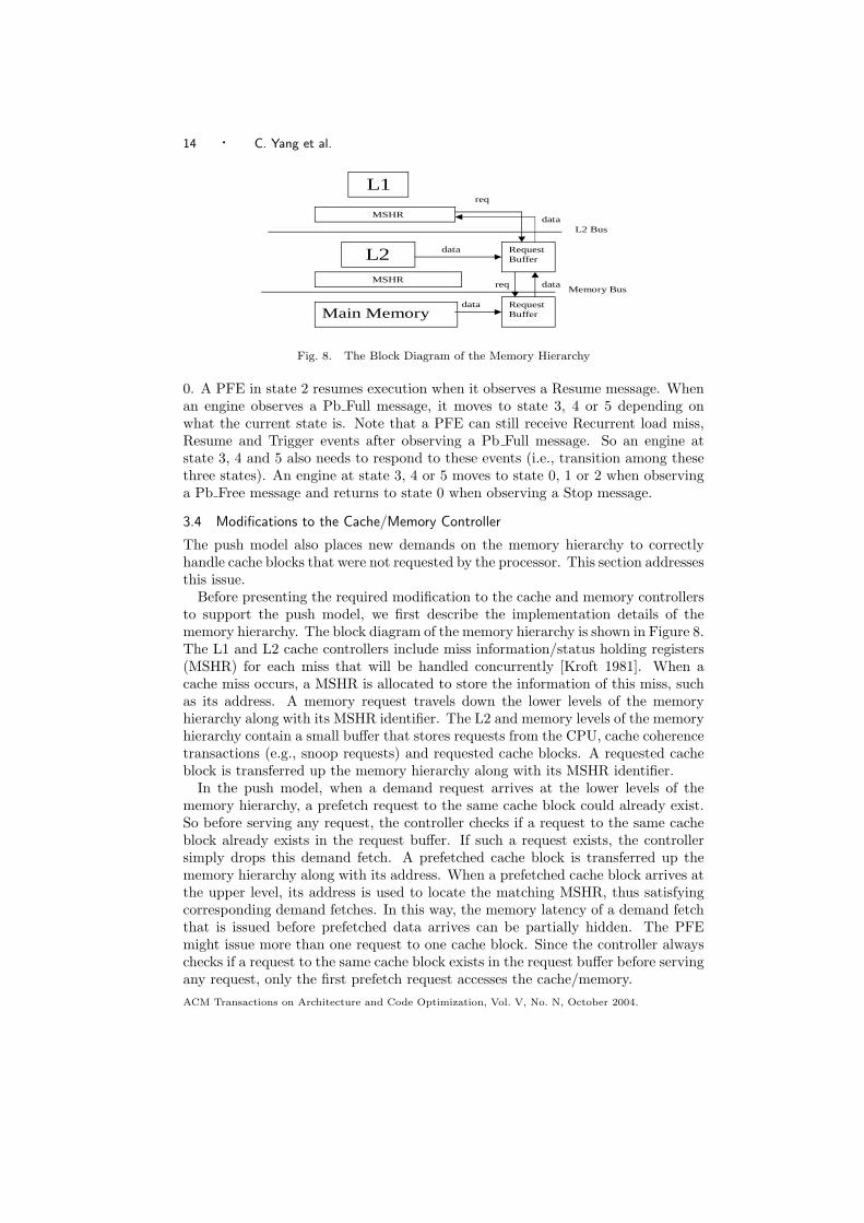
Before presenting the required modification to the cache and memory controllersto support the push model, we first describe the implementation details of thememory hierarchy. The block diagram of the memory hierarchy is shown in Figure 8.The L1 and L2 cache controllers include miss information/status holding registers(MSHR) for each miss that will be handled concurrently [Kroft 1981]. When acache miss occurs, a MSHR is allocated to store the information of this miss, suchas its address. A memory request travels down the lower levels of the memoryhierarchy along with its MSHR identifier. The L2 and memory levels of the memoryhierarchy contain a small buffer that stores requests from the CPU, cache coherencetransactions (e.g., snoop requests) and requested cache blocks. A requested cacheblock is transferred up the memory hierarchy along with its MSHR identifier.
In the push model, when a demand request arrives at the lower levels of thememory hierarchy, a prefetch request to the same cache block could already exist.So before serving any request, the controller checks if a request to the same cacheblock already exists in the request buffer. If such a request exists, the controllersimply drops this demand fetch. A prefetched cache block is transferred up thememory hierarchy along with its address. When a prefetched cache block arrives atthe upper level, its address is used to locate the matching MSHR, thus satisfyingcorresponding demand fetches. In this way, the memory latency of a demand fetchthat is issued before prefetched data arrives can be partially hidden. The PFEmight issue more than one request to one cache block. Since the controller alwayschecks if a request to the same cache block exists in the request buffer before servingany request, only the first prefetch request accesses the cache/memory.ACM Transactions on Architecture and Code Optimization, Vol. V, No. N, October 2004.

Tolerating Memory Latency through Push Prefetching for Pointer-Intensive Applications · 15
(a) 2_PFE (b) 1_PFE
L1
L2
Main Memory
PFE
PFE
PB L1
L2
Main Memory
PFE
PB
Fig. 9. Variations of the Push Architecture
It is not guaranteed that a prefetched cache block will find a correspondingMSHR. One could exist if the processor executed a load for the corresponding cacheblock. If there is no matching MSHR, the returned cache block can be stored in afree MSHR or in the request buffer. If neither one is available, this cache block isdropped. Dropping these cache blocks does not affect the program correctness, sincethey are a result of a non-binding prefetch operation, not a demand fetch from theprocessor. Before updating the cache using prefetched data, the cache controllerneeds to check if the corresponding cache block exists in the cache (redundantprefetch) to avoid keeping multiple copies of the same block in the cache.
3.5 Variations of the Push Architecture
The push architecture described above attaches the PFE to each level of the memoryhierarchy (3 PFE). To reduce the hardware cost, we present two design alternatives:2 PFE and 1 PFE. 2 PFE attaches the PFE to the L1 and main memory levels,while 1 PFE only uses one PFE at the main memory level.
Figure 9 shows the block diagram of these two architectures. 2 PFE performspull-based prefetching between the L1 and L2 cache until a recurrent load misses inthe L2 cache. As a result, data in the L2 cache is pulled up to the CPU instead ofbeing pushed up as in 3 PFE. Based on the analytical model presented in Section 2,the latency between recurrent prefetches is r1 + a1 + x1 for the pull model anda1 for the push model for objects that exist in the L2 (r1: time to send a requestfrom L1 to L2; a1: L2 access time; x1: time to transfer a cache block from L2to L1). So the push model brings data to the L1 level only r1 + x1 cycles earlierthan the pull model. For most computer systems, r1+x1 is only a small portion ofthe round-trip memory latency. So 2 PFE should perform comparably to 3 PFE.We can further reduce the hardware cost of 2 PFE if the CPU is a multithreadingprocessor. Instead of using a separate processor at the L1 level for prefetching,we can invoke a helper thread to execute the LDS traversal kernel. This approachhas been used in several pre-execution studies [Roth and Sohi 2001; Zilles and Sohi2001]. In this way, 2 PFE only needs to employ one PFE at the main level.
In the 1 PFE architecture, all prefetches are issued from the main memory level.1 PFE greatly simplifies the push architecture design because the interaction issueamong the PFEs no longer exists. 1 PFE should work effectively if a large portionof the LDS being traversed exists only in main memory. However, for applicationsin which the L2 cache is able to capture most of the L1 misses, load instructions
ACM Transactions on Architecture and Code Optimization, Vol. V, No. N, October 2004.
16 · C. Yang et al.
are resolved more slowly in the memory PFE than in the CPU. So 1 PFE may notbe able to achieve any prefetching effect because the memory PFE is very likely torun behind the CPU.
3.6 Discussion
in this section, we discuss issues on supporting the push model in the multipro-gramming and multiprocessor systems.
3.6.1 Context Switch Issues. In the multiprogramming environment, a process could suspend execution at anyinstance. The operating system is responsible for saving and restoring processstate correctly during a context switch. In the push architecture, in addition to theCPU state, the operating system also needs to save and restore the state of threePFEs if we want the PFE to resume execution at the point when it is interrupted.This incurs extra overhead for a context switch. One design alternative is to re-activate the PFE using a recurrent load miss as a triggering point when a suspendedprocess resumes execution. The traversal kernels for the running process can bedownloaded into the PFE during a context switch. The other approach is to waituntil the first instruction TLB miss occurs to download the traversal kernels. Thisrequires the operating system to associate a process’s traversal kernel informationwith its instruction TLB entries. This paper focuses on the performance impact ofthe push model on a single program, so we do not evaluate how a context switchaffects prefetching performance further.
3.6.2 Impacts on the Multiprocessor Memory Systems. To support the push model on the multiprocessor memory systems, we can attacha PFE to each memory module as proposed in [Hughes 2002]. A memory-sideprefetch engine issues prefetch requests to its local memory. The requested data ispushed back to the requesting processor if it is found in the local memory. Since theentire data structures being traversed may distribute on different memory modules,multiple memory-side PFEs need to work cooperatively to finish the prefetchingtask. The interaction scheme among PFEs at different levels of memory hierarchydescribed in Section 3.2 can be extended to handle the interaction among the PFEsat different memory modules. We leave the detailed design as future work.
4. EVALUATION
In this section, we present simulation results that demonstrate the effectiveness ofthe proposed prefetching scheme. Section 4.1 describes our simulation framework.In Section 4.2, we show the analysis of a microbenchmark to provide insight intothe performance advantage of the push model over the conventional pull model. Wethen examine the prefetching scheme in detail using a set of pointer-based applica-tions in Section 4.3. We first evaluate the performance improvement achieved bythe prefetching scheme using a single-issue processor as the PFE. We then analyzehow the issue width of a PFE affects performance. We finish by evaluating thevarious push architectures discussed in Section 3.5.ACM Transactions on Architecture and Code Optimization, Vol. V, No. N, October 2004.
Tolerating Memory Latency through Push Prefetching for Pointer-Intensive Applications · 17
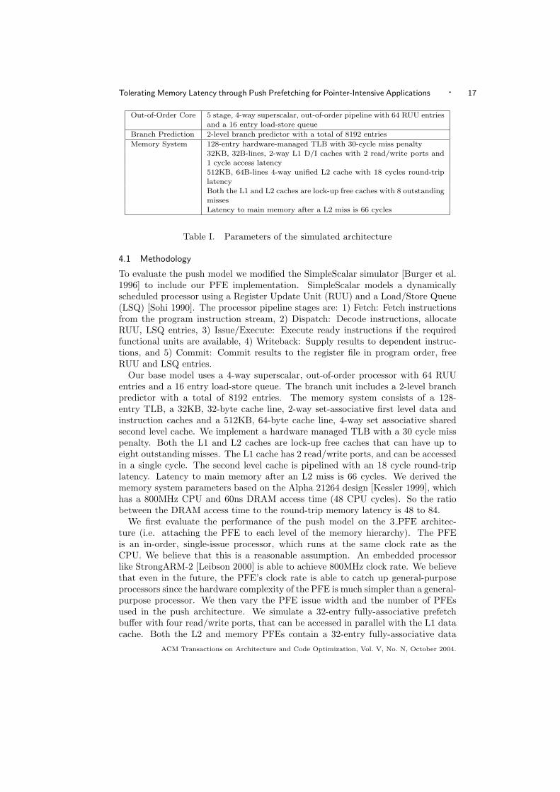
Out-of-Order Core 5 stage, 4-way superscalar, out-of-order pipeline with 64 RUU entriesand a 16 entry load-store queue
Branch Prediction 2-level branch predictor with a total of 8192 entries
Memory System 128-entry hardware-managed TLB with 30-cycle miss penalty32KB, 32B-lines, 2-way L1 D/I caches with 2 read/write ports and1 cycle access latency512KB, 64B-lines 4-way unified L2 cache with 18 cycles round-triplatencyBoth the L1 and L2 caches are lock-up free caches with 8 outstandingmissesLatency to main memory after a L2 miss is 66 cycles
Table I. Parameters of the simulated architecture
4.1 Methodology
To evaluate the push model we modified the SimpleScalar simulator [Burger et al.1996] to include our PFE implementation. SimpleScalar models a dynamicallyscheduled processor using a Register Update Unit (RUU) and a Load/Store Queue(LSQ) [Sohi 1990]. The processor pipeline stages are: 1) Fetch: Fetch instructionsfrom the program instruction stream, 2) Dispatch: Decode instructions, allocateRUU, LSQ entries, 3) Issue/Execute: Execute ready instructions if the requiredfunctional units are available, 4) Writeback: Supply results to dependent instruc-tions, and 5) Commit: Commit results to the register file in program order, freeRUU and LSQ entries.
Our base model uses a 4-way superscalar, out-of-order processor with 64 RUUentries and a 16 entry load-store queue. The branch unit includes a 2-level branchpredictor with a total of 8192 entries. The memory system consists of a 128-entry TLB, a 32KB, 32-byte cache line, 2-way set-associative first level data andinstruction caches and a 512KB, 64-byte cache line, 4-way set associative sharedsecond level cache. We implement a hardware managed TLB with a 30 cycle misspenalty. Both the L1 and L2 caches are lock-up free caches that can have up toeight outstanding misses. The L1 cache has 2 read/write ports, and can be accessedin a single cycle. The second level cache is pipelined with an 18 cycle round-triplatency. Latency to main memory after an L2 miss is 66 cycles. We derived thememory system parameters based on the Alpha 21264 design [Kessler 1999], whichhas a 800MHz CPU and 60ns DRAM access time (48 CPU cycles). So the ratiobetween the DRAM access time to the round-trip memory latency is 48 to 84.
We first evaluate the performance of the push model on the 3 PFE architec-ture (i.e. attaching the PFE to each level of the memory hierarchy). The PFEis an in-order, single-issue processor, which runs at the same clock rate as theCPU. We believe that this is a reasonable assumption. An embedded processorlike StrongARM-2 [Leibson 2000] is able to achieve 800MHz clock rate. We believethat even in the future, the PFE’s clock rate is able to catch up general-purposeprocessors since the hardware complexity of the PFE is much simpler than a general-purpose processor. We then vary the PFE issue width and the number of PFEsused in the push architecture. We simulate a 32-entry fully-associative prefetchbuffer with four read/write ports, that can be accessed in parallel with the L1 datacache. Both the L2 and memory PFEs contain a 32-entry fully-associative data
ACM Transactions on Architecture and Code Optimization, Vol. V, No. N, October 2004.
18 · C. Yang et al.
for (i = 0; i<10; i++) node = head; while (node) for (j=0; j < iters; j++) sum = sum+j; node = node->next; endwhileendfor
0%
50%
100%
150%
200%
250%
300%
2 8 14 20 26 32 38 44 50 56 62 68 74 80 86 92 98
Compute Iteration per Node Access
Sp
eed
up
(%)
Perfect Memory
Push
Push_throttle
Pull
Pull_throttle
(a) Microbenchmark Source Code (b) Push vs. Pull: Microbenchmark Results
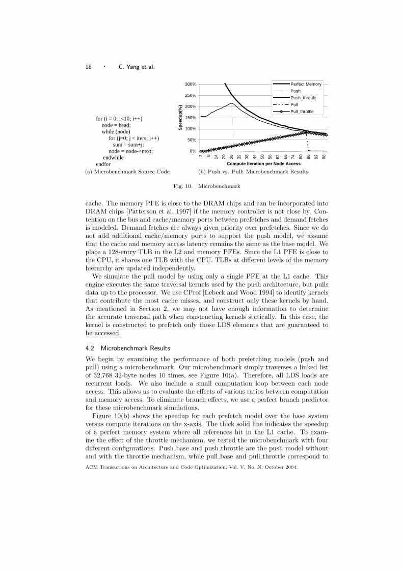
Fig. 10. Microbenchmark
cache. The memory PFE is close to the DRAM chips and can be incorporated intoDRAM chips [Patterson et al. 1997] if the memory controller is not close by. Con-tention on the bus and cache/memory ports between prefetches and demand fetchesis modeled. Demand fetches are always given priority over prefetches. Since we donot add additional cache/memory ports to support the push model, we assumethat the cache and memory access latency remains the same as the base model. Weplace a 128-entry TLB in the L2 and memory PFEs. Since the L1 PFE is close tothe CPU, it shares one TLB with the CPU. TLBs at different levels of the memoryhierarchy are updated independently.
We simulate the pull model by using only a single PFE at the L1 cache. Thisengine executes the same traversal kernels used by the push architecture, but pullsdata up to the processor. We use CProf [Lebeck and Wood 1994] to identify kernelsthat contribute the most cache misses, and construct only these kernels by hand.As mentioned in Section 2, we may not have enough information to determinethe accurate traversal path when constructing kernels statically. In this case, thekernel is constructed to prefetch only those LDS elements that are guaranteed tobe accessed.
4.2 Microbenchmark Results
We begin by examining the performance of both prefetching models (push andpull) using a microbenchmark. Our microbenchmark simply traverses a linked listof 32,768 32-byte nodes 10 times, see Figure 10(a). Therefore, all LDS loads arerecurrent loads. We also include a small computation loop between each nodeaccess. This allows us to evaluate the effects of various ratios between computationand memory access. To eliminate branch effects, we use a perfect branch predictorfor these microbenchmark simulations.
Figure 10(b) shows the speedup for each prefetch model over the base systemversus compute iterations on the x-axis. The thick solid line indicates the speedupof a perfect memory system where all references hit in the L1 cache. To exam-ine the effect of the throttle mechanism, we tested the microbenchmark with fourdifferent configurations. Push base and push throttle are the push model withoutand with the throttle mechanism, while pull base and pull throttle correspond toACM Transactions on Architecture and Code Optimization, Vol. V, No. N, October 2004.
Tolerating Memory Latency through Push Prefetching for Pointer-Intensive Applications · 19
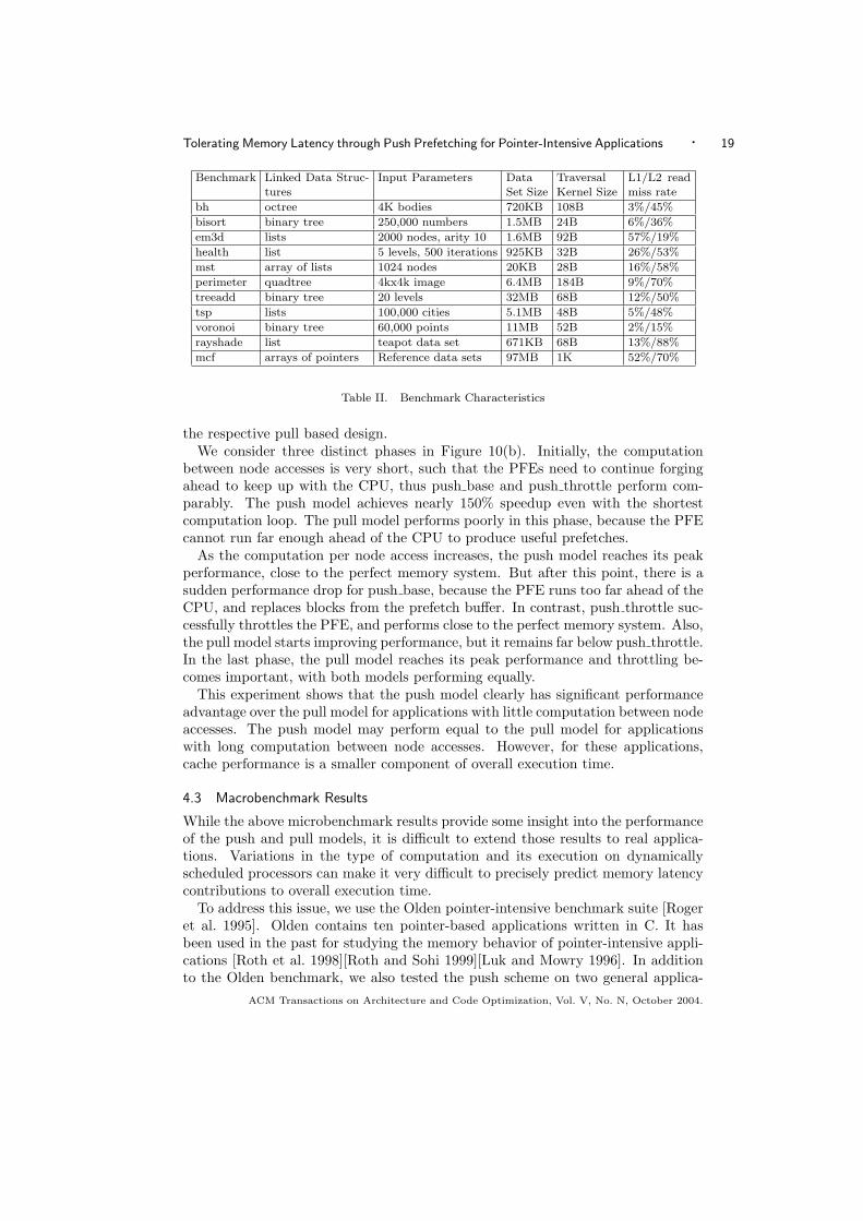
Benchmark Linked Data Struc-tures
Input Parameters DataSet Size
TraversalKernel Size
L1/L2 readmiss rate
bh octree 4K bodies 720KB 108B 3%/45%
bisort binary tree 250,000 numbers 1.5MB 24B 6%/36%
em3d lists 2000 nodes, arity 10 1.6MB 92B 57%/19%
health list 5 levels, 500 iterations 925KB 32B 26%/53%
mst array of lists 1024 nodes 20KB 28B 16%/58%
perimeter quadtree 4kx4k image 6.4MB 184B 9%/70%
treeadd binary tree 20 levels 32MB 68B 12%/50%
tsp lists 100,000 cities 5.1MB 48B 5%/48%
voronoi binary tree 60,000 points 11MB 52B 2%/15%
rayshade list teapot data set 671KB 68B 13%/88%
mcf arrays of pointers Reference data sets 97MB 1K 52%/70%
Table II. Benchmark Characteristics
the respective pull based design.We consider three distinct phases in Figure 10(b). Initially, the computation
between node accesses is very short, such that the PFEs need to continue forgingahead to keep up with the CPU, thus push base and push throttle perform com-parably. The push model achieves nearly 150% speedup even with the shortestcomputation loop. The pull model performs poorly in this phase, because the PFEcannot run far enough ahead of the CPU to produce useful prefetches.
As the computation per node access increases, the push model reaches its peakperformance, close to the perfect memory system. But after this point, there is asudden performance drop for push base, because the PFE runs too far ahead of theCPU, and replaces blocks from the prefetch buffer. In contrast, push throttle suc-cessfully throttles the PFE, and performs close to the perfect memory system. Also,the pull model starts improving performance, but it remains far below push throttle.In the last phase, the pull model reaches its peak performance and throttling be-comes important, with both models performing equally.
This experiment shows that the push model clearly has significant performanceadvantage over the pull model for applications with little computation between nodeaccesses. The push model may perform equal to the pull model for applicationswith long computation between node accesses. However, for these applications,cache performance is a smaller component of overall execution time.
4.3 Macrobenchmark Results
While the above microbenchmark results provide some insight into the performanceof the push and pull models, it is difficult to extend those results to real applica-tions. Variations in the type of computation and its execution on dynamicallyscheduled processors can make it very difficult to precisely predict memory latencycontributions to overall execution time.
To address this issue, we use the Olden pointer-intensive benchmark suite [Rogeret al. 1995]. Olden contains ten pointer-based applications written in C. It hasbeen used in the past for studying the memory behavior of pointer-intensive appli-cations [Roth et al. 1998][Roth and Sohi 1999][Luk and Mowry 1996]. In additionto the Olden benchmark, we also tested the push scheme on two general applica-
ACM Transactions on Architecture and Code Optimization, Vol. V, No. N, October 2004.
20 · C. Yang et al.
tions, Rayshade [Kolb ] and mcf. Rayshade is a real-world graphics application thatimplements a raytracing algorithm. Mcf is taken from SpecINT2K suite. Table IIlists the types of linked-data structures, the data set size and traversal kernel sizeused in this study. Note that we only list the data structure types for the traversalkernels executed by the PFEs. We omit the power application because it has alow (1%) miss rate. We evaluate the push model performance for both a perfectand 128-entry TLB. Since the proposed push architecture is designed to improvedata cache performance, by assuming a prefetch TLB, we are able to evaluate theeffectiveness of the push architecture from memory stall time reduction. Usinga realistic TLB configuration could decrease the overall execution time reductionachieved by the push architecture. However, for this set of benchmark tested, a 128-entry TLB has less than 1% impact on the push architecture performance exceptfor health 2. Therefore, we only present simulation results assuming a perfect TLBin this paper. Note that unlike the microbenchm ark results, the branch predictioneffect are considered when evaluating this set of macrobenchmarks.
4.3.1 Performance Comparison Between The Push and Pull Model. Figure 11 shows execution time normalized to the base system without prefetch-ing. For each benchmark, the three bars correspond to the base, push and pullmodels, respectively. Execution time is divided into 2 components, memory stalltime and computation time. We obtain the computation time by assuming a per-fect memory system. For the set of benchmarks with tight traversal loops (health,mst, treeadd), the push model is able to reduce between 25% and 38% of memorystall time (13% to 25% overall execution time reduction) while the pull model canonly reduce the stall time by at most 4%. Perimeter traverses down a quad-treein depth-first order, but has an unpredictable access pattern once it reaches a leaf.Therefore, we only prefetch the main traversal kernel. Although perimeter performssome computation down the leaves, it has very little computation to overlap withthe memory access when traversing the internal nodes. So the pull model is notable to achieve any speedup, but the push model reduces the execution time by 4%.
For applications that have longer computation lengths between node accesses(bh, rayshade, em3d), we expect larger reductions in memory stall time than forprograms with little computation between node accesses. From Figure 11 we seethat the push model performs close to a perfect memory system for rayshade andbh (89% and 100% memory stall time reduction), reducing execution time by 57%and 36%, respectively. The pull model achieves similar improvements for bh, butreduces execution time by only 39% for rayshade. The exception is em3d, whichshows only a 31% reduction in memory stall time and 25% in execution time, withsimilar performance for the pull model.
When the pull model performs comparable to the push model, we expect perfor-mance close to a perfect memory system (see Section 4.2). While this is true forbh, it is not for em3d. Em3d has poor L1 cache performance (57% load miss rate),but the L2 cache is able to capture 80% of these misses. For LDS elements thatexist in the L2 cache, the latency between recurrent prefetches in the pull model isr1 + a1 + x1 (r1: time to send a request from L1 to L2; a1: L2 access time; x1:
2128-entry has 5% performance impact on Health
ACM Transactions on Architecture and Code Optimization, Vol. V, No. N, October 2004.

Tolerating Memory Latency through Push Prefetching for Pointer-Intensive Applications · 21
pull
push
base
0.00
0.10
0.20
0.30
0.40
0.50
0.60
0.70
0.80
0.90
1.00
health em3d mst perimeter bh bisort treeadd tsp voronoi rayshade mcf
Nor
mal
ized
Exe
cutio
n T
ime
memory latencycomputation time
Fig. 11. Performance comparison between the push and pull model
time to transfer a cache block from L2 to L1). For the push model, the latencybetween recurrent prefetches is a1 since prefetches are issued from the L2 level.So the push model brings data to the L1 level r1 + x1 cycles earlier than the pullmodel. R1 + x1 is equal to 6 in this experiment, so the push model does not showsignificant performance improvement over the pull model for em3d.
Bisort and tsp dynamically change the data structure while traversing it. Asmentioned in Section 3, the prediction accuracy is low for this type of application.For tsp, we are able to identify some traversal kernels that do not change thestructure dynamically. The push model is able to reduce the execution time by 4%and the pull model 1%. For bisort, neither the push or pull model is able to improveperformance because the prediction accuracy is low (only 20% of prefetched cacheblocks are useful). By only prefetching one node ahead, both the push and pullcan reduce the execution time by 3%. For mcf, the data structure traversed inthe main kernel is arrays of pointers. The traversal pattern is not supported bythe interaction scheme among three PFEs described in Section 3.2. As a result,the PFE at the lower levels of the memory hierarchy is never triggered. Therefore,the push model performs the same as the pull model. 3 Voronoi uses pointers, butarray and scalar loads cause most of the cache misses. So we are not able to seeany performance improvement for either the push or pull model.
The macrobenchmark results match our expectations based on the microbench-mark analysis in the previous section. The push model is effective even when theapplications have very tight loops where the performance of the traditional pullmodel is limited because of the pointer-chasing problem. For applications withenough computation between node accesses, the push model is able to achieve per-formance close to the perfect memory system when the pull model is still not ableto deliver comparable performance.
The pull-based prefetching mechanism assumed in the above discussion does not
3We tested mcf on the 1 PFE architecture where all prefetches are issued from the main memorylevel, and observed close to 10% speedup.
ACM Transactions on Architecture and Code Optimization, Vol. V, No. N, October 2004.
22 · C. Yang et al.
0
0.1
0.2
0.3
0.4
0.5
0.6
0.7
0.8
0.9
1
1.1
health em3d mst perimeter bh bisort treeadd tsp voronoi
Nor
mal
ized
Exe
cutio
n T
ime
PushJump pointer
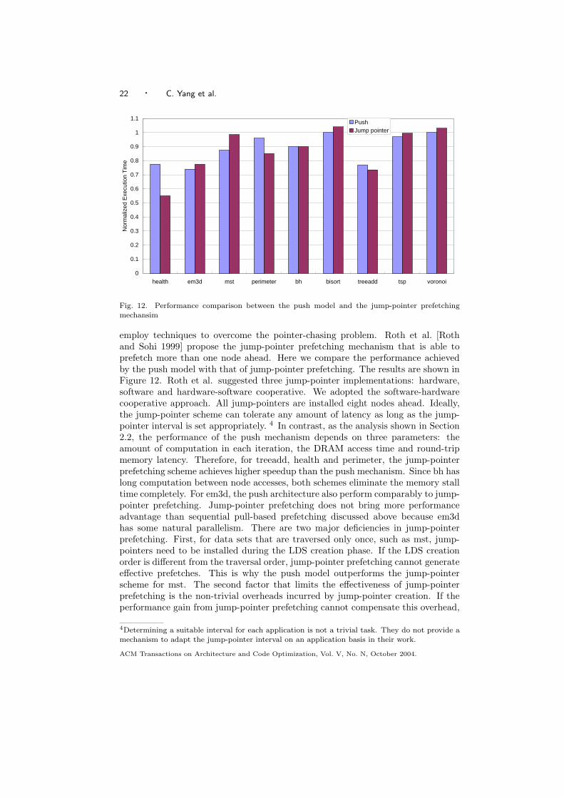
Fig. 12. Performance comparison between the push model and the jump-pointer prefetchingmechansim
employ techniques to overcome the pointer-chasing problem. Roth et al. [Rothand Sohi 1999] propose the jump-pointer prefetching mechanism that is able toprefetch more than one node ahead. Here we compare the performance achievedby the push model with that of jump-pointer prefetching. The results are shown inFigure 12. Roth et al. suggested three jump-pointer implementations: hardware,software and hardware-software cooperative. We adopted the software-hardwarecooperative approach. All jump-pointers are installed eight nodes ahead. Ideally,the jump-pointer scheme can tolerate any amount of latency as long as the jump-pointer interval is set appropriately. 4 In contrast, as the analysis shown in Section2.2, the performance of the push mechanism depends on three parameters: theamount of computation in each iteration, the DRAM access time and round-tripmemory latency. Therefore, for treeadd, health and perimeter, the jump-pointerprefetching scheme achieves higher speedup than the push mechanism. Since bh haslong computation between node accesses, both schemes eliminate the memory stalltime completely. For em3d, the push architecture also perform comparably to jump-pointer prefetching. Jump-pointer prefetching does not bring more performanceadvantage than sequential pull-based prefetching discussed above because em3dhas some natural parallelism. There are two major deficiencies in jump-pointerprefetching. First, for data sets that are traversed only once, such as mst, jump-pointers need to be installed during the LDS creation phase. If the LDS creationorder is different from the traversal order, jump-pointer prefetching cannot generateeffective prefetches. This is why the push model outperforms the jump-pointerscheme for mst. The second factor that limits the effectiveness of jump-pointerprefetching is the non-trivial overheads incurred by jump-pointer creation. If theperformance gain from jump-pointer prefetching cannot compensate this overhead,
4Determining a suitable interval for each application is not a trivial task. They do not provide amechanism to adapt the jump-pointer interval on an application basis in their work.
ACM Transactions on Architecture and Code Optimization, Vol. V, No. N, October 2004.

Tolerating Memory Latency through Push Prefetching for Pointer-Intensive Applications · 23
0
0.1
0.2
0.3
0.4
0.5
0.6
0.7
0.8
0.9
1
1.1
health em3d mst rayshade perimeter bh treeadd tsp
Nor
mal
ized
Exe
cutio
n T
ime
basepush_basepush_bufferpush_throttlepush_buffer_throttle
Fig. 13. Effect of the PFE Data Cache and Throttle Mechanism
jump-pointer prefetching could actually degrade performance. That is the reasonfor the adverse effect caused by jump-pointer prefetching for tsp, bisort and voronoi.Both bisort and tsp have dynamically changing structures, and voronoi has morearray/scalar loads than pointer loads. Even though the push architecture does notshow performance benefit for these applications either, it does not incur significantrun-time overheads as jump-pointer prefetching. Overall, the push architectureperforms comparably to jump-pointer prefetching. Jump-pointer prefeching onlyshows 1.6% average performance advantage over the push model.
Since bisort, mcf and voronoi do not benefit from the push model, we omit theseapplications in the following discussion.
4.3.2 Effect of the PFE data cache and Throttle Mechanism. Recall that the push architecture uses two mechanisms to avoid redundant andearly prefetches: the PFE data cache and throttle mechanism. The result pre-sented above show the combined effect of both features. In this section, we eval-uate the effect of the PFE data cache and throttle mechanism separately in Fig-ure 13. Push base is a plain push model with no data caches or throttle mechanism.Push throttle is push base with throttling and push buffer is push base with datacaches in the L2 and memory PFEs. The performance impact from these twotechniques are not exclusive. The data caches can speed up PFE execution, whilethrottling slows down the PFE execution when they run too far ahead. There-fore, push buffer throttle shows the combined effect of both features, which is thepreviously presented results in Figure 11.
From Figure 13 we can see that em3d and treeadd benefit most from data caches.Push base is only able to reduce execution time by 12% for em3d. Adding a datacache (push buffer) further reduces execution time by 20%. Treeadd does not showperformance improvement for push base but push buffer reduces execution time by25%. Perimeter does not see performance improvement comparing push base andpush buffer. However, adding this feature on top of the throttle mechanism (i.e.
ACM Transactions on Architecture and Code Optimization, Vol. V, No. N, October 2004.
24 · C. Yang et al.
0%
10%
20%
30%
40%
50%
health em3d mst rayshade perimeter bh treeadd tsp
% o
f pr
efet
ches
L2
Memory
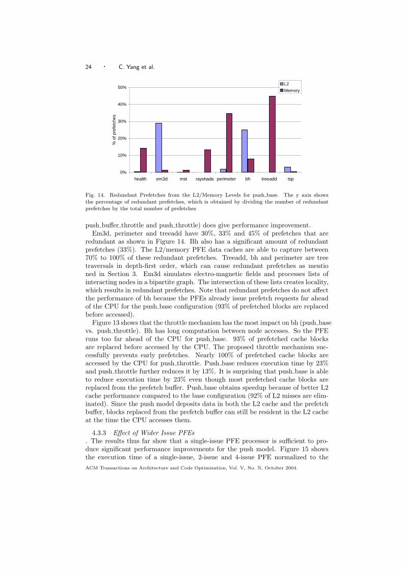
Fig. 14. Redundant Prefetches from the L2/Memory Levels for push base. The y axis showsthe percentage of redundant prefetches, which is obtained by dividing the number of redundantprefetches by the total number of prefetches
push buffer throttle and push throttle) does give performance improvement.Em3d, perimeter and treeadd have 30%, 33% and 45% of prefetches that are
redundant as shown in Figure 14. Bh also has a significant amount of redundantprefetches (33%). The L2/memory PFE data caches are able to capture between70% to 100% of these redundant prefetches. Treeadd, bh and perimeter are treetraversals in depth-first order, which can cause redundant prefetches as mentioned in Section 3. Em3d simulates electro-magnetic fields and processes lists ofinteracting nodes in a bipartite graph. The intersection of these lists creates locality,which results in redundant prefetches. Note that redundant prefetches do not affectthe performance of bh because the PFEs already issue prefetch requests far aheadof the CPU for the push base configuration (93% of prefetched blocks are replacedbefore accessed).
Figure 13 shows that the throttle mechanism has the most impact on bh (push basevs. push throttle). Bh has long computation between node accesses. So the PFEruns too far ahead of the CPU for push base. 93% of prefetched cache blocksare replaced before accessed by the CPU. The proposed throttle mechanism suc-cessfully prevents early prefetches. Nearly 100% of prefetched cache blocks areaccessed by the CPU for push throttle. Push base reduces execution time by 23%and push throttle further reduces it by 13%. It is surprising that push base is ableto reduce execution time by 23% even though most prefetched cache blocks arereplaced from the prefetch buffer. Push base obtains speedup because of better L2cache performance compared to the base configuration (92% of L2 misses are elim-inated). Since the push model deposits data in both the L2 cache and the prefetchbuffer, blocks replaced from the prefetch buffer can still be resident in the L2 cacheat the time the CPU accesses them.
4.3.3 Effect of Wider Issue PFEs. The results thus far show that a single-issue PFE processor is sufficient to pro-duce significant performance improvements for the push model. Figure 15 showsthe execution time of a single-issue, 2-issue and 4-issue PFE normalized to theACM Transactions on Architecture and Code Optimization, Vol. V, No. N, October 2004.
Tolerating Memory Latency through Push Prefetching for Pointer-Intensive Applications · 25
0
0.1
0.2
0.3
0.4
0.5
0.6
0.7
0.8
0.9
1
health em3d mst rayshade perimeter bh treeadd tsp
Nor
mal
ized
Exe
cutio
n T
ime
base
single
2issue
4issue
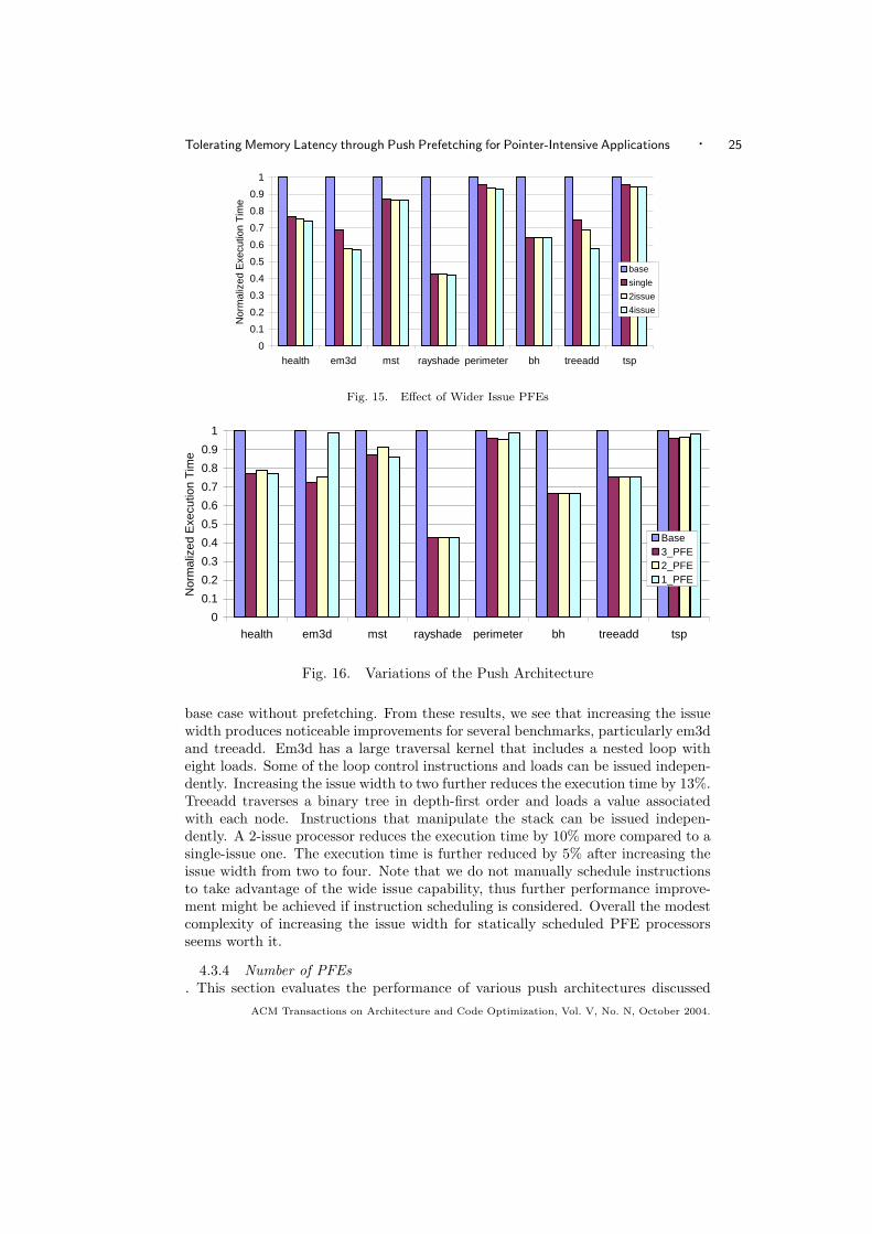
Fig. 15. Effect of Wider Issue PFEs
0
0.1
0.2
0.3
0.4
0.5
0.6
0.7
0.8
0.9
1
health em3d mst rayshade perimeter bh treeadd tsp
Nor
mal
ized
Exe
cutio
n T
ime
Base 3_PFE2_PFE1_PFE
Fig. 16. Variations of the Push Architecture
base case without prefetching. From these results, we see that increasing the issuewidth produces noticeable improvements for several benchmarks, particularly em3dand treeadd. Em3d has a large traversal kernel that includes a nested loop witheight loads. Some of the loop control instructions and loads can be issued indepen-dently. Increasing the issue width to two further reduces the execution time by 13%.Treeadd traverses a binary tree in depth-first order and loads a value associatedwith each node. Instructions that manipulate the stack can be issued indepen-dently. A 2-issue processor reduces the execution time by 10% more compared to asingle-issue one. The execution time is further reduced by 5% after increasing theissue width from two to four. Note that we do not manually schedule instructionsto take advantage of the wide issue capability, thus further performance improve-ment might be achieved if instruction scheduling is considered. Overall the modestcomplexity of increasing the issue width for statically scheduled PFE processorsseems worth it.
4.3.4 Number of PFEs. This section evaluates the performance of various push architectures discussed
ACM Transactions on Architecture and Code Optimization, Vol. V, No. N, October 2004.

26 · C. Yang et al.
in Section 3.5: 3 PFE, 2 PFE and 1 PFE. 3 PFE attaches the PFE to each levelof the memory hierarchy, which is the push architecture examined so far. 2 PFEattaches the PFE to the L1 and main memory levels, which performs pull-basedprefetching until a recurrent load misses in the L2 cache. 1 PFE only uses oneengine at the main memory level, so all prefetches are issued from the bottom ofthe memory hierarchy. Figure 16 shows execution time of these three architecturesnormalized to the base configuration.
From Figure 16 we see that the performance of 2 PFE is comparable to 3 PFE.This indicates that 3 PFE gains most of its performance from pushing data upto the L2 level. 1 PFE achieves similar performance to 3 PFE and 2 PFE for allbenchmarks except for em3d. As mentioned in Section 3.5, 3 PFE issues most ofthe prefetches at the L2 level for em3d because 80% of L1 misses are satisfied bythe L2 cache. For the 1 PFE architecture, all prefetches are now issued at the mainmemory level instead. If a LDS node exists in the L2 cache, it takes r1 + a1 + x1cycles (r1: sending a request from L1 to L2; a1: L2 access; x1: transferring acache block back to L1) to fetch a node up to the processor. For 1 PFE, thelatency between recurrent prefetches is the DRAM access time, which is larger thanr1 + a1 + x1 for the configuration tested (48 vs. 18 cycles). In this case, 1 PFE isnot able to produce any prefetching effect. 2 PFE can deliver similar performanceto 3 PFE because it simply performs pull-based prefetching. For em3d, the pullmodel performs comparably to the push model as shown in Figure 11.
From this experiment we know that 2 PFE achieves comparable performance to3 PFE for all benchmarks. 1 PFE only needs one prefetch engine but it performspoorly if the L2 cache is able to capture most of the L1 misses, like em3d. Asmentioned in Section 3.5, 2 PFE only needs one PFE if the CPU is a multithreadingprocessor, which is the trend for future processors [Gwennap 1998]. Therefore,2 PFE is the best design choice considering both cost and performance.
5. RELATED WORK
Early data prefetching research focused on array-based applications with regularaccess patterns. Hardware prefetching detects array access strides from the addresshistory at run time [Jouppi 1990][Baer and Chen 1991][Fu and Patel 1992]. Softwareprefetching [Callahan et al. 1991][Porterfield 1989][Klaiber and Levy 1991][Mowryet al. 1992] exploits compile-time information to insert prefetch instructions in aprogram. Correlation-based prefetching [Joseph and Grunwald 1997][Alexanderand Kedem 1996] also relies the address history to predict future references, butthey can capture complex access patterns. The prediction accuracy relies on thesize of the prediction table and stable access patterns.
The Spaid scheme [Lipasti et al. 1995] proposed by Lipasti et al. is a compiler-based pointer prefetching mechanism. It inserts prefetch instructions for the ob-jects pointed by pointer arguments at call sites. Luk et al. [Luk and Mowry 1996]propose three compiler-based prefetching algorithms, greedy, history-pointer anddata-linearization prefetching. Chilimbi et al. [Chilimbi et al. 1999][Chilimbi et al.1999] reorganize data layouts to improve cache performance for irregular applica-tions. Zhang et al. [Zhang and Torrellas 1995] use object information to guideprefetching for irregular applications in shared-memory multiprocessors. MehrotraACM Transactions on Architecture and Code Optimization, Vol. V, No. N, October 2004.
Tolerating Memory Latency through Push Prefetching for Pointer-Intensive Applications · 27
et al. [Mehrotra and Harrison 1996] extends stride detection schemes to captureboth linear and recurrent access patterns. Roth et al. [Roth et al. 1998][Roth andSohi 1999] propose a dynamic scheme to capture LDS traversal kernels and a jump-pointer prefetching framework to overcome the pointer-chasing problem. Ideally,the jump-pointer scheme can tolerate any amount of latency as long as the jump-pointer interval is set appropriately. However, determining a suitable interval foreach application is not a trivial task. Roth et. al do not provide a mechanismto adapt the jump-pointer interval on an application basis. Moreover, there areseveral limitations on jump-pointer prefetching. First, the jump-pointer schemeincurs non-trivial run-time overhead, therefore, it could cause adverse effects onperformance for applications with traversal patterns that is not suitable for jump-pointer prefetching (e.g., dynamically changing data structures). Even though thepush architecture does not work well for highly dynamic structures either, we donot degrade performance. Second, the performance of jump-pointer is affected bythe number of traversals performed on data sets since it requires one pass to installjump pointers. For applications that traverse data sets only once, jump-pointershave to be installed during structure construction. If the construction order is differ-ent from the traversal order, jump-point prefetching is not able to generate correctfuture addresses. The push architecture does not have this limitation. Third, sincejump-pointer prefetching relies on earlier traversals to install jump-pointers, it doesnot work well if traversal orders change frequently (e.g., tree searching). In con-trast, the push architecture executes traversal kernels to generate future addresses,therefore, it can still provide correct prefetches even traversal orders are not fixed.Karlsson et al. [Karlsson et al. 1999] presents a prefetch array approach, whichaggressively prefetches all possible nodes a few iterations ahead. The downside ofthis approach is that it could issue many unnecessary prefetches.
Several studies [Patterson et al. 1997][Kang et al. 1999] [Oskin et al. 1998] alsocombine processing power and memory in the same chip. The main function ofDRAM processors is performing computation. Impulse [Carter et al. 1999] providesconfigurable physical address remapping in the memory controller to improve busand cache utilization. The memory controller is also capable of prefetching data.But they only prefetch next cache line and data are not pushed up the memoryhierarchy as proposed in this work. Concurrent with this study, Hughes [Hughes2002] evaluates memory-side prefetching in multiprocessor systems. His schemedoes not provide solutions for two important design issues of the push model: theinteraction protocol among prefetch engines at different memory modules and amechanism to synchronize the CPU and PFE execution. Solihin et al. [Solihinet al. 2002] also propose a memory-side prefetching scheme. They adopt the pushmodel proposed in this work. They employ correlation prefetching, , and target atgeneral irregular applications instead of linked data structures as this work. Eventhough they solve many problems in conventional correlation prefetching, theirperformance is still limited if repeated access patterns are absent. In contrast, ourscheme does not rely on the past address history for future address prediction.
Some work also proposes using a separate processor for memory access. Struc-tured memory access [Pleszkun and Davidson 1983] and the Decoupled Access Ex-ecute [Smith 1982b] try to overlap demand memory requests with computation.
ACM Transactions on Architecture and Code Optimization, Vol. V, No. N, October 2004.
28 · C. Yang et al.
VanderWiel et al. [VanderWiel and Lilja 1999] proposes a separate processor forprefetching purposes for regular applications. Recently, several studies [Annavaramet al. 2001; Collins et al. 2001; Dundas and Mudge 1997; Roth and Sohi 2001; Sun-daramoorthy et al. 2000; Zilles and Sohi 2001; Luk 2001] suggest using pre-executionto improve cache performance for irregular applications. The idea of pre-executionis to execute a sequence of instructions (speculative slice) early and speculativelyto hide memory latency. They either employ a separate processor at the L1 levelto execute a speculative slice or simply invoke a helper thread if the CPU is amultithreading processor. This is essentially the pull model that we evaluate, andit can be limited by the conventional pull based data movement.
6. CONCLUSIONS
In this paper, we propose a cooperative hardware/software prefetching frameworkfor linked data structures – the push architecture. The push architecture uses aprefetch engine (PFE) to execute LDS traversal kernels (instructions that traverseLDSs) ahead of the CPU, thus successfully generating future addresses. LDS traver-sal kernels are constructed statically. The PFE is attached to each level of thememory hierarchy. Cache blocks accessed by these processors are pushed up tothe CPU. The push model decouples the pointer dereference (obtaining the nextnode address) from the transfer of the current node up to the processor and allowsimplementations to pipeline these two operations. In this way, the latency betweenrecurrent prefetches is reduced to only the DRAM access time as opposed to round-trip memory latency (including latency to access L1/L2 caches and bus transfer)in a pull-based prefetching scheme.
Our simulation results show that the push architecture is able to reduce 13% to23% of the overall execution time for applications with very tight loops, which thetraditional pull model is not able to run ahead of CPU to give significant perfor-mance improvement. Tree traversals benefit most from adding a small data cache inthe L2/memory PFEs (e.g., treeadd). We have also shown that the proposed throt-tle mechanism successfully adjusts the prefetch distance to avoid early prefetches.For applications with enough computation between node accesses, the push archi-tecture is able to achieve performance comparable to a perfect memory system.Simulations also show that the 2 PFE architecture, which only attaches the PFEto the L1 and main memory levels, performs comparably to 3 PFE, which attachesthe PFE to each level of the memory hierarchy. We also compare the push ar-chitecture against jump-pointer prefetching, which is the state-of-art pulled-basedprefetching mechanism, and find that the push architecture provides comparableaverage performance with jump-pointer prefetching.
REFERENCES
Alexander, T. and Kedem, G. 1996. Distributed predictive cache design for high performancememory system. In Proceedings of the 2th International Symposium on High-PerformanceComputer Architecture.
Annavaram, M. M., Patel, J. M., and Davidson, E. S. 2001. Data prefetching by depen-dence graph precomputation. In Proceedings of the 28th Annual International Symposium onComputer Architecture. 52–61.
Baer, J.-L. and Chen, T.-F. 1991. An effective on-chip preloading scheme to reduce data accesspenalty. In Proceedings of the 1991 Conference on SuperComputing. 176–186.
ACM Transactions on Architecture and Code Optimization, Vol. V, No. N, October 2004.
Tolerating Memory Latency through Push Prefetching for Pointer-Intensive Applications · 29
Burger, D. C., Austin, T. M., and Bennett, S. 1996. Evaluating future microprocessors-the simplescalar tool set. Tech. Rep. 1308, Computer Sciences Department, University ofWisconsin–Madison. July.
Callahan, D., Kennedy, K., and Porterfield, A. 1991. Software prefetching. In Proceedingsof the Fourth International Conference on Architectural Support for Programming Languagesand Operating Systems (ASPLOS IV). 40–52.
Carter, J., Hsieh, W., Stoller, L., Swanson, M., and Zhang, L. 1999. Impulse: Buildinga smarter memory controller. In Proceedings of 5th Symposium High-Performance ComputerArchitecture. 70–79.
Chilimbi, T. M., Davidson, B., and Larus, J. R. 1999. Cache-conscious struture definition. InProceedings of the SIGPLAN ’99 Conference on Programming Language Design and Imple-mentation. 13–24.
Chilimbi, T. M., Hill, M. D., and Larus, J. R. 1999. Cache-conscious struture layout. InProceedings of the SIGPLAN ’99 Conference on Programming Language Design and Imple-mentation. 1–12.
Collins, J. D., Wang, H., Tullsen, D. M., Christopher, H. J., Lee, Y. F., Lavery, D., andShen, J. P. 2001. Speculative precomputation: Long-range prefetching of delinquent loads. InProceedings of the 28th Annual International Symposium on Computer Architecture. 14–25.
Dundas, J. and Mudge, T. 1997. Improving data cache performance by pre-executing instruc-tions under a cache miss. In Proceedings of the ACM International Conference on Supercom-puting. 176–186.
Fu, J. W. C. and Patel, J. H. 1992. Stride directed prefetching in scalar processors. In Pro-ceedings of the 25th Annual International Symposium on Microarchitecture. 102–110.
Gwennap, L. 1998. Alpha 21364 to ease memory bottleneck. Microprocessor Report .
Hughes, C. J. 2002. Prefetching linked data structures in systems with merged dram-logic. M.S.thesis, Department of Computer Science, University of Illinois at Urbana-Champaign.
Joseph, D. and Grunwald, D. 1997. Prefetching using markov predictors. In Proceedings of the24th Annual International Symposium on Computer Architecture. 252–263.
Jouppi, N. P. 1990. Improving direct-mapped cache performance by the addition of a smallfully-associative cache and prefetch buffers. In Proceedings of the 17th Annual InternationalSymposium on Computer Architecture. 364–373.
Kang, Y., Huang, W., Yoo, S.-M., Keen, D., Ge, Z., Lam, V., Pattnaik, P., and Torrellas,J. 1999. Flexram: Toward an advanced intelligent memory system. In Proceedings of the 1999International Conference on Computer Design. 192–201.
Karlsson, M., Dahlgren, F., and Stenstrom, P. 1999. A prefetching technique for irregu-lar accesses to linked data structures. In Proceedings of Sixth Symposium High-PerformanceComputer Architecture. 206–217.
Kessler, R. E. 1999. The alpha 21264 microprocessor. IEEE Micro, 34–36.
Klaiber, A. C. and Levy, H. M. 1991. An architecture for software-controlled data prefetching.In Proceedings of the 18th Annual International Symposium on Computer Architecture. 43–53.
Kolb, C. The rayshade user’s guide. In http://graphics.stanford.edu/- cek/-rayshade.
Kroft, D. 1981. Lockup-free instruction fetch/prefetch cache organization. In Proceedings of the8th Annual International Symposium on Computer Architecture. 81–87.
Lebeck, A. and Wood, D. 1994. Cache profiling and the spec benchmarks: A case study. InIEEE Computer. 15–26.
Leibson, S. 2000. Xscale (strongarm-2) muscles in. Microprocessor Report .
Lipasti, M. H., Schmidt, W. J., Kunkel, S. R., and Roediger, R. R. 1995. Spaid: Softwareprefeteching in pointer- and call-intensive environments. In Proceedings of the 28th AnnualInternational Symposium on Microarchitecture.
Luk, C.-K. 2001. Tolerating memory latency through software-controlled pre-execution in simul-taneous multithreading processors. In Proceedings of the 28th Annual International Symposiumon Computer Architecture. 40–51.
ACM Transactions on Architecture and Code Optimization, Vol. V, No. N, October 2004.
30 · C. Yang et al.
Luk, C.-K. and Mowry, T. C. 1996. Compiler based prefetching for recursive data structure. InProceedings of the Seventh International Conference on Architectural Support for ProgrammingLanguages and Operating Systems (ASPLOS VII). 222–233.
Mehrotra, S. and Harrison, L. 1996. Examination of a memory access classification scheme forpointer-intensive and numeric program. In Proceedings of the 10th International Conferenceon Supercomputing. 133–139.
Mowry, T. C., Lam, M. S., and Gupta, A. 1992. Design and evaluation of a compiler algorithmfor prefetching. In Proceedings of the Fifth International Conference on Architectural Supportfor Programming Languages and Operating System. 62–73.
Oskin, M., Chong, F. T., and Sherwood, T. 1998. Active pages: a computation model forintelligent memory. In Proceedings of the 25th Annual International Symposium on ComputerArchitecture. 192–203.
Patterson, D., Andreson, T., Cardwell, N., Fromm, R., Keaton, K., Kazyrakis, C.,Thomas, R., and Yellick, K. 1997. A case for intelligent ram. IEEE Micro, 34–44.
Pleszkun, A. R. and Davidson, E. S. 1983. Strutured memory access architecture. In Prceedind-ings of International Conference on Parallel Processing. 461–471.
Porterfield, A. K. 1989. Software methods for improvement of cache performance on super-computer applications. Ph.D. thesis, Department of Computer Science, Rice University.
Roger, A., Carlisle, M., Reppy, J., and Hendren, L. 1995. Supporting dynamic data struc-tures on distributed memory machines. ACM Transactions on Programming Languages andSytems 17, 2 (March).
Roth, A., Moshovos, A., and Sohi, G. 1998. Dependence based prefetching for linked datastructures. In Proceedings of the Eigth International Conference on Architectural Support forProgramming Languages and Operating Systems (ASPLOS VIII). 115–126.
Roth, A. and Sohi, G. 1999. Effective jump-pointer prefetching for linked data structures. InProceedings of the 26th Annual International Symposium on Computer Architecture. 111–121.
Roth, A. and Sohi, G. 2001. Speculative data-driven multithreading. In Proceedings of 7thSymposium High-Performance Computer Architecture. 134–143.
Smith, B. 1982a. Architecture and applications of the hep multiprocessor computer system. InProceedings of the Int. Soc. for Opt. Engr. 241–248.
Smith, J. E. 1982b. Decoupled access/execute computer architectures. In Proceedings of the 9thAnnual International Symposium on Computer Architecture. 112–119.
Sohi, G. 1990. Instruction issue logic for high performance, interruptable, multiple functionalunit, pipelined computers. IEEE Transactions on Computers 39, 3 (March), 349–359.
Solihin, Y., Lee, J., and Torrellas, J. 2002. Using a user-level memory thread for correla-tion prefetching. In Proceedings of the 29th Annual International Symposium on ComputerArchitecture. 171–182.
Sundaramoorthy, K., Purser, Z., and Rotenberg, E. 2000. Slipstream processors: Improvingboth performance and fault tolerance. In ASPLOS9. 257–268.
VanderWiel, S. and Lilja, D. J. 1999. A compiler-assisted data prefetch controller. Tech. Rep.ARCTiC-99-05, Department of Electrical and Computer Engineering, University of Minnesota.May.
Yang, C. and Lebeck, A. R. 2000. Push vs. pull: Data movement for linked data structures. InProceedings of the ACM International Conference on Supercomputing. 176–186.
Zhang, Z. and Torrellas, J. 1995. Speeding up irregular applications in shared-memory multi-processors: Memory binding and group prefetching. In Proceedings of the 22nd Annual Inter-national Symposium on Computer Architecture. 188–200.
Zilles, C. B. and Sohi, G. 2001. Execution-base prediction using speculative slices. In Proceed-ings of the 28th Annual International Symposium on Computer Architecture. 2–13.
ACM Transactions on Architecture and Code Optimization, Vol. V, No. N, October 2004.