to increase energy efficiency
TRANSCRIPT
Furnaces
Glass International February 2020
www.glass-international.com
25
Continued>>
In-furnace thermal surveys to increase energy efficiencyNeil G Simpson* looks at how to increase energy efficiency using in-furnace thermal glass surveys.
Thermal images from static permanently mounted near infrared borescope thermal imagers can
be used to trouble-shoot and optimise furnaces in terms of glass quality and yield, furnace pull, asset protection, and energy and emission reduction.
Ametek Land’s NIR-B Glass thermal imaging cameras have been operating continuously since 2014 with more than 50 reference installations in glass melting furnaces globally, more recently, transportable instruments are being used to perform dedicated in-furnace thermal surveys of glass melt tanks.
The potential scope of a survey is significant, and the challenge is to decide the priority of what to look at. With more than 324,000 thermal data points in one image, the analysis and interpretation of the data can take longer than the time taken to take the actual measurements. The amount of data measured and recorded is contingent on the customer site in terms of access, preparation and quality of utilities. The equipment used is almost the same as used in the fixed system but without the automatic
retraction mechanism, however, for extended surveys or regenerator repairs, a retraction system may be utilised to protect the instrument.
The in-furnace thermal glass survey is not an alternative to a conventional traditional refractory inspection but a supplementary service.
The thermal imager design is straight and does not have the potential for a 90-degree angle as in conventional endoscopic photographs. The imager can generate equivalent colour and black and white (B&W) images, however, also shows the actual temperature of the refractory when the flame is off.
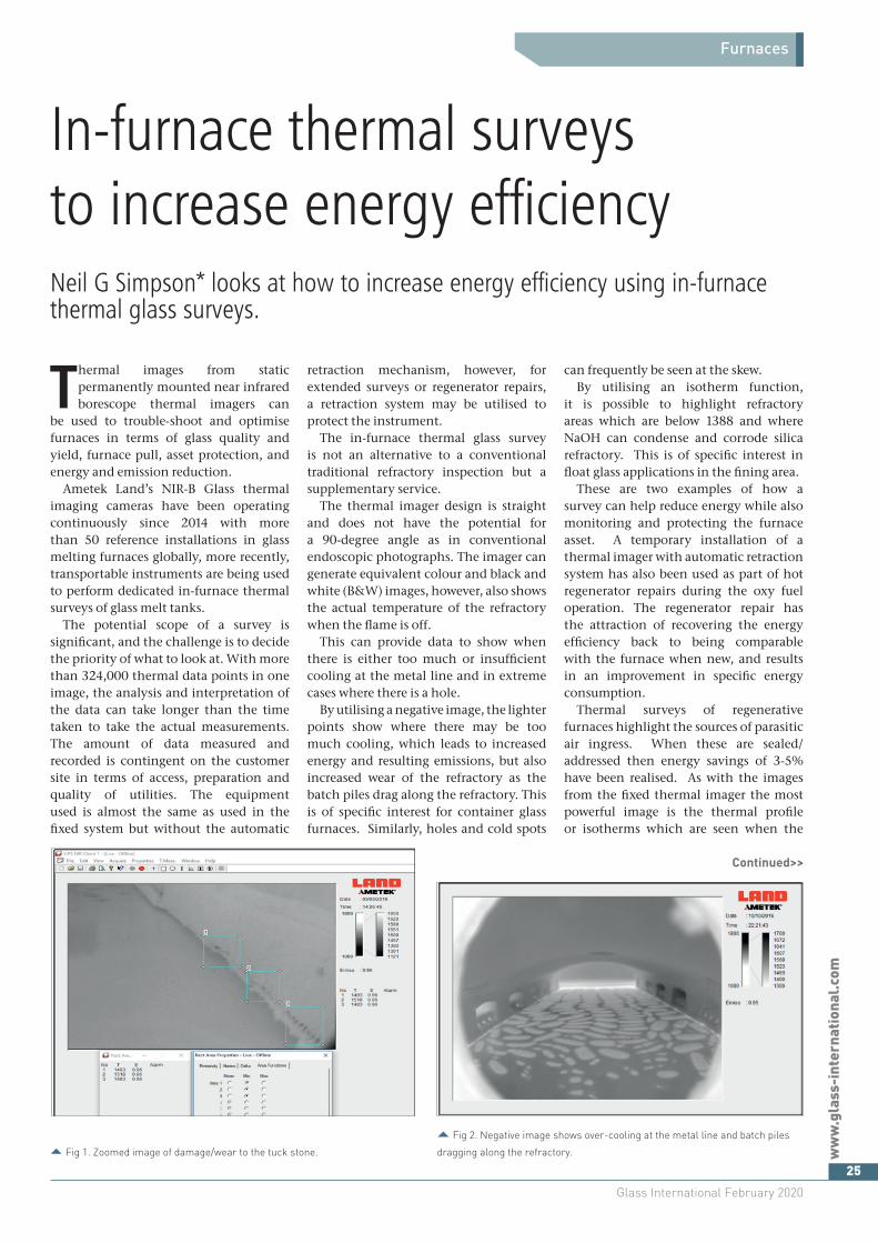
This can provide data to show when there is either too much or insufficient cooling at the metal line and in extreme cases where there is a hole.
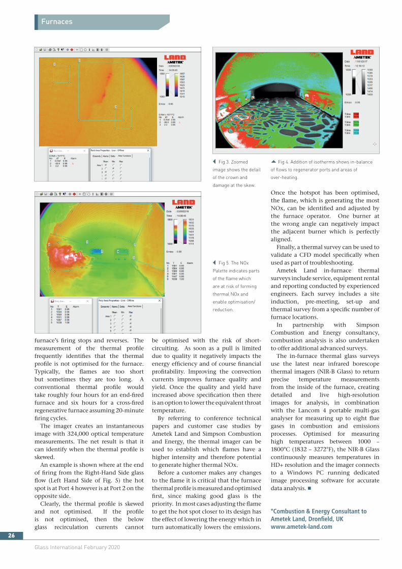
By utilising a negative image, the lighter points show where there may be too much cooling, which leads to increased energy and resulting emissions, but also increased wear of the refractory as the batch piles drag along the refractory. This is of specific interest for container glass furnaces. Similarly, holes and cold spots
can frequently be seen at the skew. By utilising an isotherm function,
it is possible to highlight refractory areas which are below 1388 and where NaOH can condense and corrode silica refractory. This is of specific interest in float glass applications in the fining area.
These are two examples of how a survey can help reduce energy while also monitoring and protecting the furnace asset. A temporary installation of a thermal imager with automatic retraction system has also been used as part of hot regenerator repairs during the oxy fuel operation. The regenerator repair has the attraction of recovering the energy efficiency back to being comparable with the furnace when new, and results in an improvement in specific energy consumption.
Thermal surveys of regenerative furnaces highlight the sources of parasitic air ingress. When these are sealed/addressed then energy savings of 3-5% have been realised. As with the images from the fixed thermal imager the most powerful image is the thermal profile or isotherms which are seen when the
� Fig 2. Negative image shows over-cooling at the metal line and batch piles
dragging along the refractory.� Fig 1. Zoomed image of damage/wear to the tuck stone.
Furnaces
Glass International February 2020
026
furnace’s firing stops and reverses. The measurement of the thermal profile frequently identifies that the thermal profile is not optimised for the furnace. Typically, the flames are too short but sometimes they are too long. A conventional thermal profile would take roughly four hours for an end-fired furnace and six hours for a cross-fired regenerative furnace assuming 20-minute firing cycles.
The imager creates an instantaneous image with 324,000 optical temperature measurements. The net result is that it can identify when the thermal profile is skewed.
An example is shown where at the end of firing from the Right-Hand Side glass flow (Left Hand Side of Fig. 5) the hot spot is at Port 4 however is at Port 2 on the opposite side.
Clearly, the thermal profile is skewed and not optimised. If the profile is not optimised, then the below glass recirculation currents cannot
be optimised with the risk of short-circuiting. As soon as a pull is limited due to quality it negatively impacts the energy efficiency and of course financial profitability. Improving the convection currents improves furnace quality and yield. Once the quality and yield have increased above specification then there is an option to lower the equivalent throat temperature.
By referring to conference technical papers and customer case studies by Ametek Land and Simpson Combustion and Energy, the thermal imager can be used to establish which flames have a higher intensity and therefore potential to generate higher thermal NOx.
Before a customer makes any changes to the flame it is critical that the furnace thermal profile is measured and optimised first, since making good glass is the priority. In most cases adjusting the flame to get the hot spot closer to its design has the effect of lowering the energy which in turn automatically lowers the emissions.
� Fig 5. The NOx
Palette indicates parts
of the flame which
are at risk of forming
thermal NOx and
enable optimisation/
reduction.
Once the hotspot has been optimised, the flame, which is generating the most NOx, can be identified and adjusted by the furnace operator. One burner at the wrong angle can negatively impact the adjacent burner which is perfectly aligned.
Finally, a thermal survey can be used to validate a CFD model specifically when used as part of troubleshooting.
Ametek Land in-furnace thermal surveys include service, equipment rental and reporting conducted by experienced engineers. Each survey includes a site induction, pre-meeting, set-up and thermal survey from a specific number of furnace locations.
In partnership with Simpson Combustion and Energy consultancy, combustion analysis is also undertaken to offer additional advanced surveys.
The in-furnace thermal glass surveys use the latest near infrared borescope thermal imagers (NIR-B Glass) to return precise temperature measurements from the inside of the furnace, creating detailed and live high-resolution images for analysis, in combination with the Lancom 4 portable multi-gas analyser for measuring up to eight flue gases in combustion and emissions processes. Optimised for measuring high temperatures between 1000 – 1800°C (1832 – 3272°F), the NIR-B Glass continuously measures temperatures in HD+ resolution and the imager connects to a Windows PC running dedicated image processing software for accurate data analysis. �
*Combustion & Energy Consultant to Ametek Land, Dronfield, UKwww.ametek-land.com
� Fig 3. Zoomed
image shows the detail
of the crown and
damage at the skew.
� Fig 4. Addition of isotherms shows in-balance
of flows to regenerator ports and areas of
over-heating.