to enjoy safe operation, read and fully understand the … operati… · to enjoy safe operation,...
TRANSCRIPT

To enjoy safe operation, read and fully understand thecontents of this Operating Manual before attemptingto operate the equipment.
Store this Operating Manual in a safe and convenientplace where it can be referred to easily when needed.

Thank you very much for purchasing our product, HE-770. ■ Please be sure to read this operating manual carefully and understand the
contents before the actual operation in order to keep your safety. ■ Please store this manual safely at the convenient place so that you can read it
when needed. ■ Please pass this manual to new owner when you resell or give this unit to
someone else. ■ We are not responsible for any physical injuries and property damages under
product liability (PL) law by wrong usage or any other operations not described in this manual.
INTRODUCTION
・Do not reproduce a part or all of contents described in this manual without our
approval.
・Please understand that the unit may differ from the contents described in this
manual due to the specifications change etc.
・Please inform us if you see any errors and/or unclear descriptions in this manual.
DEFINITION OF SYMBOL MARK [CAUTION FOR SAFETY]
: Incur the accident resulting in the death or serious woundunless you keep the descriptions.
: Be in danger of incurring the accident resulting in the
death or serious wound unless you keep the descriptions. : Be in danger or incurring the slight wound to human or
damage to other physical property unless you keep thedescriptions.
: Prohibited : Obligation

TABLE OF CONTENTS 1. CAUTION ON SAFETY (BE SURE TO READ THIS)·····························1
1-1. CAUTION ON SAFETY···································································1 1-2. HANDLING OF CABLE···································································2 1-3. HANDLING OF TRANSDUCER AND WATER TEMP SENSOR ····3 1-4. TFT LCD PANEL ·············································································3 1-5. CAUTION OF OPERATION ····························································4
2. FEATURE ································································································5 3. SPECIFICATIONS···················································································6 4. STANDARD CONFIGURATION······························································7 5. DIMENSION ····························································································8 6. INSTALLATION OF UNIT ·······································································9 7. BUILT-IN INSTALLATION ·····································································10 8. CONNECTION WITH UNIT ···································································12 9. INSTALLATION OF TRANSDUCER·····················································13
9-1. INSIDE-HULL ················································································14 9-2. THRU-HULL ··················································································14 9-3. INSIDE CASE················································································15
10. CONNECTING DIAGRAM ··································································16 11. DESCRIPTION OF KEYS ···································································17
11-1. FRONT PANEL············································································17 12. DISPLAY INFORMATION ···································································18 13. OPERATION························································································19
13-1. POWER KEY···············································································19 13-2. BRIGHTNESS KEY·····································································19 13-3. CLUTTER····················································································20 13-4. SHIFT KEY··················································································21 13-5. GAIN KEY····················································································22 13-6. RANGE KEY ···············································································23 13-7. MODE KEY··················································································24 13-8. USER KEY ··················································································25 13-9. AUTO KEY···················································································26 13-10. MENU KEY················································································26
14. MENU LIST AND EACH MEANING ···················································27 15. MENU ··································································································29 16. FUNCTIONS IN MENU ·······································································30
16-1. MENU 1·······················································································30 Sweep Speed··············································································30 Display Image ·············································································30 Scale Line ···················································································31

Water Temp Graph······································································31 Color Configuration ·····································································31 Background Color ·······································································31
16-2. MENU 2·······················································································32 Expansion Ratio ··········································································32 A-Mode························································································32 Split Screen·················································································32 Water Temp Alarm·······································································33 Depth Alarm ················································································33 Fish Alarm ···················································································34 Battery Alarm···············································································34 Unit Set ·······················································································34
Temp Unit············································································34 Depth Unit ···········································································35
Adjust ··························································································35 Keel Offset ··········································································35 Water Temp·········································································35 Voltage ················································································35
Other Set·····················································································36 Auto Range ·········································································36 Clean Echo ·········································································36 Output Power ······································································36 Pulse Length ·······································································37 Auto Key ·············································································38
Readout 1····················································································39 Depth ··················································································39 Super Range·······································································39 Depth Marker ······································································40 Color Bar·············································································40
Readout 2····················································································40 Latitude/Longitude ······························································40 Vessel Speed ······································································40 Bearing················································································40
System Menu ··············································································41 Simulation ···········································································41 Display ················································································41 System Reset······································································42
17. THEORY OF FISHFINDER ·································································43 18. CAUTION OF SAFETY ·······································································45

This section explains the important cautions in order to prevent the users and surrounding people from physical injuries and property damages.
1-1. CAUTION ON SAFETY
1. CAUTION ON SAFETY (BE SURE TO READ THIS)
● High voltage is used for the unit inside. No one besides authorized personnel should disassemble ormodify the unit. If not followed, it may result in electronic shock.
※Please be sure to consult with the local dealer for any repairs.
● Install the unit firmly. If not, it may cause the accidents such as human injuries.
● Do not use the information displayed on the screen for navigation.
It causes the marine accidents and incidents. ※Be sure to use the official marine charts for navigation judgement.
● Do not operate the unit while piloting the vessel.
It causes the marine accidents and incidents. ※Be sure to confirm the surrounding safety before the usage.
● Do not put the power on in the presence of flammable materials.
It causes the fire. ● Do not use the power supply besides the specified one.
It causes the firing and heating. ● Do not disassemble and modify the unit.
It causes the firing, electronic shock, and injury. ● Do not operate the unit with wet hands.
It causes the electronic shock and damage. ● Disconnect the power cable in the case of problem, smoke, and fire.
It causes the firing and electronic shock. Be sure to contact the shop or customer support.
1

2
1-2. HANDLING OF CABLE
● Do not install the unit where rain or spray dashes hit directly. It causes the firing and electronic shock.
● Do not install the unit at heated places.
It causes the firing from the increase of internal temperature, injury, and electronic shock.
● Away from direct sun light. It causes the difficulty of future vision and heat problem.
● Be sure to use the specified power supply cable. It causes firing and heating.
● Do not leave the power plug after its removal.
It causes firing and heating if the plug gets wet. ● Be sure to wire the cables in order for safety pilot.
The improper wiring causes the accident. ※Do not put the heavy object on cables or bend cables excessively.
● Do not disassemble or modify the cables. It causes to firing, heating, or electronic shock.
● Do not use damaged cables.
It causes firing or electronic shock.
● Do not pull out the cable when disconnecting the plug. The cable damage causes firing and electronic shock. ※Be sure to hold and pull the plug itself for the removal.
● Do not put any pressures on cables when installing the unit.
It causes line cut and shortage.

3
1-3. HANDLING OF TRANSDUCER AND WATER TEMP SENSOR
● Any works on the boat are very unstable and risky. Installation/maintenance of transducer and water temp sensor shouldbe handled after landing the vessel on ground or fixing the vessel atshipyard etc.
● Be sure to ventilate well inside the vessel when installing the transducer at the bottom of vessel. Volatile gas from solvent etc causes the toxic symptoms.
● Water proof treatment is required for Thru-Hull installation. If not, it causes the marine accident. ※It is not allowed for aluminum vessels due to the risk of corrosion.
● Do not operate the electronic tools with wet hands.
It causes electronic shock. ● Do not remove the transducer plug when the power is ON.
It causes electronic shock.
● Only use with selected transducers and water temp sensors. The use of wrong parts may cause the damage on the unit.
1-4. TFT LCD PANEL
● TFT LCD panel is made with high precision technology. Therefore, the
effective pixel is over 99%, and pixel loss and continuous lighting pixel exist0.01% or more. Please understand the specifications.

1-5. CAUTION OF OPERATION
Battery voltage varies when the engine starts. It may cause some damage onto the unit. Set the power OFF when starting the engine. * Battery may go flat by operating the unit with engine off condition.
Power OFF when Starting Engine
Operate the unit within the range of DC 11V~35V.
Power Supply 11-35V
Do not clean the unit with organic solution like thinner or alcohol etc becausemost parts are made with plastic. For heavy dirt, soak the soft cloth in synthetic detergent and clean it after wring.
Organic Solution is Prohibited
The unit is not designed for storing the data permanently. Important datashould be recorded on the notebook etc.
Take Note of Important Data
4

2. FEATURE
★Dual frequency (50kHz/200kHz) is supported. ★Crystal clear precision 7 inch wide LCD (LED backlight) ★Low power consumption
★Automatic gain/depth control function ★Multiple installations supported
Display mode can be changed (vertical/horizontal) for different installations.
★Easy panel operation Each key is assigned for best location to support user friendly operation.
5

3. SPECIFICATIONS
Display 7 inch Wide Color LCD Number of Pixel 480×234
Operating Voltage DC11V~35V Power Consumption 8.4W
Dimension 230(H)×236(W)×108(D)mm Weight Approx. 1.4Kg
Frequency 50, 200kHz Output Power 600W
Display
Depth Range 3~1000m Auto Range OFF/Range/Shift Auto Gain OFF/ON
A –mode Display OFF/ON Fish Alarm OFF / /
Temp Alarm OFF/Within Range/Out of Range Depth Alarm OFF/Within Range/Out of Range
Expansion Mode Bottom Lock/Auto Exp/Manual Exp Expansion Ratio x2, x4, x8 Sweep Speed 6 Steps + Freeze
Background Color 4 Colors (Black, Blue, White, Dark Blue) Color Configuration 6 Patterns
Depth Unit Meter/Feet/Fathoms/Brazas Super Range OFF/ON Pulse Width Short/Medium/Long Clean Echo OFF/Weak/Strong
Transmitting Output High/Low Depth Display OFF/Small/Large
Simulation Mode OFF/ON Voltage Display ○
Water Temp Display ○ Temp Sensor Option
Function
Backlight LED 5 steps �Specifications and appearance are subject to change without further notice.
6
7
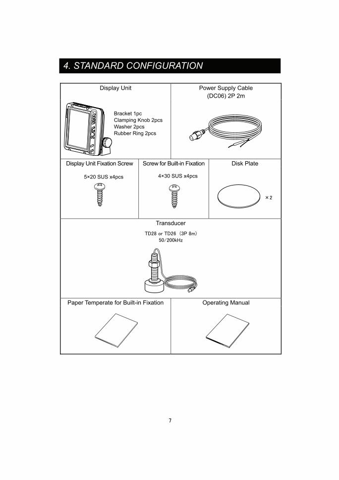
Display Unit Power Supply Cable (DC06) 2P 2m
Display Unit Fixation Screw Screw for Built-in Fixation Disk Plate
Transducer
Paper Temperate for Built-in Fixation Operating Manual
4. STANDARD CONFIGURATION
Bracket 1pc Clamping Knob 2pcsWasher 2pcs Rubber Ring 2pcs
4×30 SUS x4pcs 5×20 SUS x4pcs
×2
TD28 or TD26 (3P 8m)
50/200kHz

5. DIMENSION <Display Unit> Unit : mm
<Bracket Holes>
8

9
6. INSTALLATION OF UNIT
● Install the unit firmly.
If not, it may cause the human injuries. �Install the unit correctly according to the following instruction. �For overhead mounting, install the unit to safe location with the consideration of dropping incident.
● Install the unit to the location with less vibration.
[Procedure of Installation] <Installation of Unit>
Fix the unit with enclosed screws by using bracket holes(4 locations). Refer to the picture below.
1.<Positioning> Set the unit with mounting bracket and fixation spot. Put the mark. �Leave some room in the backside of unit for cable connections.
2.<Installation of Bracket> Fix it with enclosed screws by using 4 holes on the bracket. �The cutting slits for both edges of bracket’s face to front side.
3.<Installation of Unit> Refer to the picture below and fix the unit.
Display Unit
Rubber Ring
Put the disk plate for unused hole for knob.
Clamping Knob
Tapping Screw 5×20 SUS
Washer

10
7. BUILT-IN INSTALLATION
● Install the unit firmly. If not, it may cause the human injuries. �Install the unit correctly according to the following instruction.
[Procedure of Built-in Installation] Fix the unit by using 4 holes on the front panel.
Cover for built-in installation(4 locations)
1. Create the space by using the enclosed paper temperate for built-in installation.
Unit : mm
108.
5
188
108.
5
※This drawing faces from the front panel.
M4 screws locations
188
Bui l t- in size
66 37
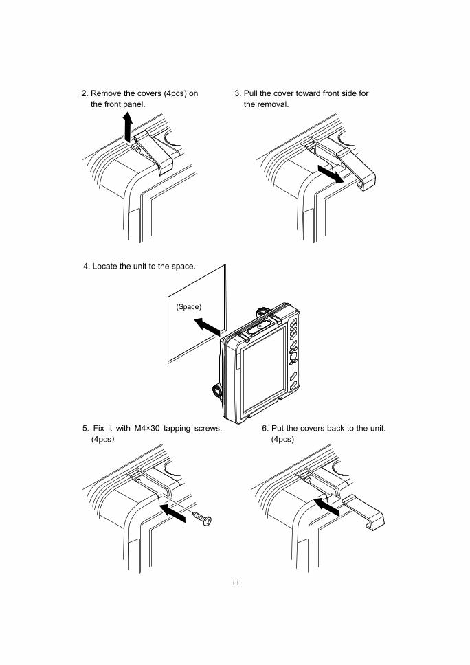
2. Remove the covers (4pcs) on the front panel.
5. Fix it with M4×30 tapping screws. (4pcs)
6. Put the covers back to the unit. (4pcs)
3. Pull the cover toward front side for the removal.
(Space)
4. Locate the unit to the space.
11

8. CONNECTION WITH UNIT
12
Temp Sensor (Option)
NMEA Input/Output
Transducer (TD28 or TD26)
Battery 11~35V DC
White (+) Black (-)

13
9. INSTALLATION OF TRANSDUCER
[Installation Methods] The following installations can be applied. Please refer to the each instruction. 1. Inside-Hull 2. Thru-Hull 3. Inside Case �These methods prohibit the use of aluminum vessels for the risk of corrosion. �Be careful about the following points when using the method 1 and 3.
No protruding object in front oftransducer such as screw outdeck plate and drain. Transducer
2/3 from the bow.
Do not install the transducer atthe tilted locations more than 15°.
Do not install the transducer at the locationshaving obstruction like keel etc.
● Any works on the boat are very unstable and risky. Installation/maintenance of transducer and water temp sensor shouldbe handled after landing the vessel on ground or fixing the vessel at shipyard etc.
● Be sure to ventilate well inside the vessel when installing the transducer at the bottom of vessel. Volatile gas from solvent etc causes the toxic symptoms.
● Water proof treatment is required for Thru-Hull installation. If not, it causes the marine accident.
● Do not operate the electronic tools with wet hands.
It causes electronic shock.

�Effective for FRP vessels with single hull layer of 10mm or less. Look for the best picture location before the fixation by putting adequate water on the transducer surface and vessel bottom followed by pressing the transducer onto the vessel bottom. (1)Polish the adhesive surface (transducer bottom surface and vessel bottom) well
with sandpaper(#240 or around) and alcohol in order to remove oil, water, and dirt on the surface.
(2)Put silicon bond on the adhesive surface (transducer bottom surface and vessel bottom) and press firmly for the bonding so that no air bubble is contained inside.
9-2. THRU-HULL
9-1. INSIDE-HULL
Single layer(10mm or less)vessel bottom
BondVessel bottom
Transom
(1)Make a hole of approx. φ23 at the vessel bottom. (Alminum vessels are not subject to the installation for the risk of corrosion.)
(2)Insert the screw part of transducer into the hole and fix it with 1pc cork washer, 1pc washer, and 1pc nut. (Extra cork washer is for spare.)
�Execute the water proof care for the junction part. For tilted hull, use a block etc to face directly to the vessel bottom.
Keep the inclination of transducer surfacebelow 10°or less.
Washer Nut
Cork
Hull Block
Put the seal at jointpoint for waterproof.
Put the seal at joint point for waterproof.
Hull
Cork
NutWasher
14

9-3. INSIDE CASE
�Effective for FRP vessels with single hull layer of 10mm or less.
Look for the best picture location before the fixation by putting the transducer inside the case.
(1)Take out all the water inside the case. (2)When installing the transducer at the bottom of case, please refer to “9-1 INSIDE-HULL”.
Single layer(10mm or less)
Fish tank
15

Connector for Input/Output Used for NMEA input/output.
Transfer Rate Data Format Transfer Format
NMEA0183 Start bit=1, Data bit=8 4800 bps (GGA, VTG) Parity bit =none, Stop bit=1
10. CONNECTING DIAGRAM
NMEA Unit
Data output
External power
Input/Output Connector
NMEA Input/Output
16

11-1. FRONT PANEL
11. DESCRIPTION OF CONTROL KEYS
①Power ON key (→page 19) Set the power ON.
②Power OFF key (→page 19)
Set the power OFF. ③Brightness key (→page 19)
Adjust the backlight brightness. ④Zoom key (→page 24)
Change the display mode. Display changes every time pressing this key.
Exp OFF → B/L → Auto Exp → Manual Exp ⑤User key (→page 25)
Customized key assignment by user. ⑥Direction key (→page 29)
Move the depth marker with [ , ] key. Select the item when menu is activated.
⑦Auto key (→page 26)
Set the sensitivity and depth automatically. Press this key to activate/deactivate Auto mode (gain/range).
⑧Menu key (→page 26)
Display menu. ⑨Clutter key (→page 20)
Adjust the clutter. ⑩Shift key (→page 21)
Shift the display. ⑪⑫Gain key (→page 22)
Adjust the sensitivity. ⑬Range key (→page 23)
Change the depth range.
17

12. DISPLAY INFORMATION Dual frequency mode ※1
18
Longitude
Speed
Direction
Latitude
Voltage Depth unitDepth Water temp display
2nd echo
Color bar
Shown only under auto mode.
Auto mode display
Sweep speed
Frequency display for the right side
Frequency display for the left side When using the specific mode, the selected mode (B/L, Auto Exp, or Man Exp)
Time marker
Gain bar
30sec bar appears every minute.
Depth marker
Fish school
200kHz mode
50kHz mode
Depth
Sea bottom
※2
(Optional water temp sensor is required.)
※1 Frequency display
Display appears differently for single and dual frequency. ※2 Display Lattitude/Longitude/Speed/Direction when connecting to NMEA
(GGA,VTG) device. (Activate NMEA display ON in menu 2.)

13-2. BRIGHTNESS KEY
13-1. POWER KEY
13. OPERATION
Power ON/OFF Set the power ON/OFF of unit. P1 ress&Hold [ON] key for 1sec or more to set the power ON after alarm sound. The display appears on the screen. Press [OFF] key to set the power OFF after alarm sound. ※[OFF] key is disabled during the star-up until the
display appears on the screen.
Caution1) Set the power OFF when starting the engine because the battery voltage varies causing the problems into unit.
ON key OFF key
Brightness Adjustment
Brightness key
Press [BRIGHT] key for brighter. Press [BRIGHT] key for darker.
1 Adjust the brightness.
19

13-3. CLUTTER KEY
Clutter
Press clutter key to adjust the color. The color bar on the left side changes. Press&Hold [CLUTTER] key to remove he color of weak reflection. t Press&Hold [CLUTTER] key to display the color of strong reflection.
[Clutter] Fish school or sea bottom is shown by the strength of reflected echo and color configuration. “Clutter” removes the color from the weak echo so that plankton or water contamination are reduced for easier detection of fish school etc.
1 Clutter key
Color bar
20

13-4. SHIFT KEY
Possible to shift the display range of depth. For example, execute 10m shift to 0~8m display range. The changed range will be 10~18m. Also, you can expand small target with this feature.
Shift key 1
Press shift key to move the display range. Depth display is changed. [Shift to shallow direction] Press [SHIFT] key toward shallow direction. [Shift to deep direction] Press [SHIFT] key toward deep direction. ※Shift key is disabled when selecting
automatic range.
10m shift
Shift (Display Range Shift)
21

13-5. GAIN KEY [Sensitivity] Adjust the sensitivity in order to detect the sea bottom and fish school. (Numeric and bar display of 32 steps from 0~31) The optimized sensitivity is where 2nd reflected echo appears some on the screen. [2nd echo] 1st echo is the primary reflected echo from the sea bottom. 2nd echo is that reflected 1st echo on the water surface returning to the sea bottom followed by reflecting back to the water surface once again. Normally, 2nd echo is located around twice deeper than 1st echo.
22
<Too poor sensitivity> <Good> <Too much sensitivity>
As image is pale, it isdifficult to distinct the fishschool.
As 2nd reflection isshown, it is easy todistinct the fish school.
As plankton and stainare shown, it is difficultto distinct the fish.
Sea bottom
Gain AdjustmentPress gain key to adjust the sensitivity. [Higher sensitivity] Press [GAIN-1] or [GAIN-2] key for high sensitivity and longer bar. (Numeric value beside gain bar goes up.) [Lower sensitivity] Press [GAIN-1] or [GAIN-2] key for low sensitivity and shorter bar. (Numeric value beside gain bar goes down.) �Use [GAIN-1] key to change the sensitivity of upper&right display of dual frequency. Use [GAIN-2] key to change the sensitivity of lower&left display.
1
Gain 2
Gain 1
Left display Sensitivity bar
Right display Sensitivity bar
2nd echo

13-6. RANGE KEY [Depth (Display Range)] Set-up the depth (display range) from the water surface. Select from 23 steps: Min 0~3m to Max 0~1000m.
23
538
1015
2030
4050
6080
100125
150180
200250
300400
500
m
0
600800
1000
Depth key [Deep range] Press [RANGE] key for deep range.
Press range key to change the depth. The display range of depth changes. [Shallow range] Press [RANGE] key for shallow range.
1
Depth Range (Display Range)

13-7. ZOOM KEY
Press key to change the mode. Current selection is shown on the top left of screen. Normal picture appears when zoom mode is OFF. (Bottom Lock) Bottom contour is indicated as a straight line. (Auto. Expansion) The bottom is expanded and shown. (Expansion range marker cannot be moved.) (Manual Expansion) Selected area is expanded and shown. Move the direction key [ , ] to select the target area.
There are 3 different zoom selections: bottom lock expansion, automatic expansion, and manual expansion. Expansion range mark appears when selecting auto and manual expansion.
1
Zoom mode key
Expansion range marker
24

13-8. USER KEY
<MENU 1>
1 SWEEP2 PICTURE3 SCALE LINE4 TEMP GRAPH5 COLOR6 BACK GRD
[FRZ,1,2,3,4,×2,×3][50+200][OFF,ON][OFF,2°,10°][1,2,3,4,5,6][ ]
[MENU]:TO MENU 2
Press key (user). Set-up display appears. Set-up is changed in order every time pressing key. Direction key [ , ] can be used to change the set-up as well. Set-up display disappears after pressing
key (user) or direction key [ , ] for 2sec or more. Also, you can clear the set-up display by pressing any keys other than key (user). ※Default set-up is set to “sweep speed”. ※Allocation method of user key
Look for underlined items in menu display. These functions can be assigned for user key.
Select the function from menu. Press&Hold key (user) for 2sec or more. The underline of selected function gets thicker after beep sound.
Possible to assign the selected function to user key. By doing so, there is no need to go into the set-up from menu display. All you need is to press user key for faster, easy, convenient function.
1
Underline 1
3 2
2 User key
25

13-10. MENU KEY
13-9. AUTO KEY
Press key to display Menu 1 and 2. Direction key [ , ] to select. Direction key [ , ] to change the set-up. Press or key to end the set-up display. ※Refer to page29 for Menu in details.
Use key, direction key [ , , , ], key, and key to select the
function from menu display. The detailed set-up can be selected from menu key.
1
Direction key
Menu key
Press auto key to set automatic function ON/OFF. Go to Menu 2 Auto Key Setting for auto key set-up. (→page 38)
Auto key
Press key (auto) to display AUTO on
the top left of screen.
1
Press key (auto) again to go back to normal operation.
26

14. MENU LIST AND EACH MEANING
MENU 1 MEANING 1.SWEEP Set the sounding rate per one sweep.
FRZ 1 2 3 4 x2 x3 2.PICTURE Set the frequency of display on screen.
50 200 200+50 50+200 3.SCALE LINE Indicate the line on the depth graduation.
OFF ON 4.TEMP GRAPH Display water temp graph. (Water temp sensor is optional.)
OFF 2° 10° 5.COLOR Select the color configuration of reflected strength. (except background color)
1 2 3 4 5 6 6.BACK GRD Select the background color of display.
Black Blue White Dark blue
MENU 2 MEANING 1.EXP RATE Set the expansion rate at expansion mode.
×2 ×4 ×8 2.A-MODE Display the strength of reflected signal.
OFF ON 3.SPLIT SCREEN Split the screen left/right or up/down.
L/R U/D 4.ALARM 1.TEMP ALARM 1.ALARM SET Alarm is ON within or exceeding the range of 2
temperature. OFF IN RANGE, OUT RANGE 2.TEMP SET 1 Set the temperature 1.
0~40℃(default: 15℃) 3.TEMP SET 2 Set the temperature 2.
0~40℃(default: 20℃) 2.DEPTH
ALARM 1.ALARM SET Alarm is ON within or exceeding the range of 2
depth. OFF IN RANGE, OUT RANGE 2.DEPTH SET 1 Set the depth 1.
1~500m(default: 10m) 3.DEPTH SET 2 Set the depth 2.
1~500m(default: 100m) 3.FISH ALARM Alarm is ON when fish is detected.
OFF
4.BATT ALARM Alarm is ON when battery voltage drops. OFF 12V(10V or less) 24V(21V or less)
5.OTHERS 1.UNIT SET 1.TEMP UNIT Select the unit of water temp. ℃ ˚F
2.SCALE UNIT Select the unit of depth. m ft Fa br
2.ADJUST 1.KEEL OFFSET Keel offset can be applied to indicate the depth from the water surface. 0.0~5.0m (default: 0.0m)
2.TEMP ADJ Select temp offset. -5.0~+5.0℃ (default: 0.0℃)
3.VOLT ADJ Select voltage offset. -2.0~+2.0V (default: 0.0V)
3.OTHER SET 1.AUTO R MAX DEP.
Select the search range when executing the auto range function. 30m 50m 100m 200m 300m 500m
2.CLEAN ECHO Display fine image with less noise. OFF L H
3.OUTPUT POWER Change the transmitting power. LOW HIGH
※ : default set-up
27

28
MENU 2 MEANING
4.PULSE LENGTH Select the pulse width. S M L
5.AUTO KEY SET Enable/Disable following automatic functions. 1.AUTO G: Adjust the sensitivity automatically. OFF ON 2.AUTO R: Adjust the depth automatically. OFF RNG SFT
4.READOUT 1 1.DEPTH DIG Select the depth digit size. OFF S L
2.SUPER RANGE Whole picture synchronizes to the changed depth. OFF ON
3.DEPTH MARKER Select the color of depth marker. OFF W R G B Y LB P
4.COLOR BAR Set the indication of color bar. OFF ON
5.READOUT 2 1.LAT/LON ※Activated only when connecting to NMEA output device. Select the display of latitude/longitude. OFF ON
2.BOAT SPEED Set the indication of boat speed. OFF ON
3.BEARING Set the bearing. OFF ON
6. SYSTEM MENU
1.SIMULATION Activate the simulation. OFF ON
2.DISPLAY Set the display direction. LANDSCAPE PORTRAIT L REV. P REV.
3.SYSTEM RESET Reset the set-up to the factory set-up. ※ : default set-up

29
15. MENU
<MENU 1>
1 SWEEP2 PICTURE3 SCALE LINE4 TEMP GRAPH5 COLOR6 BACK GRD
[FRZ,1,2,3,4,×2,×3][50+200][OFF,ON][OFF,2°,10°][1,2,3,4,5,6][ ]
[MENU]:TO MENU 2
<MENU 2>1 EXP RATE2 A-MODE3 SPLIT SCREEN4 ALARM5 OTHERS
[×2,×4,×8][OFF,ON]
[L/R,U/D]
[MENU]:TO FINISH MENU
Operation To display Menu mode Press key to display Menu 1.
To change the contents of Menu Use direction key [ , , , ] to select and
change each item.
Selected items are shown in yellow frame.
・ to move up.
・ to move down.
・ to move right or enlarge the value.
・ to move left or lower the value.
To go to next MENU ・When Menu 1 is opened, press key to
show Menu 2.
・When Menu 2 is opened, press key to
clear the menu display.
To cancel MENU mode ・Set-up menu appears for the items having
mark on the right by pressing or
key.
・Press key to return to the previous
menu display.
※Operation may vary depending on the menu item. ※Selected items are activated even after the power is set to OFF.
1 Menu
Direction key 2
3
4 key to Menu 2
[[ , ] to change the set-up
[ , ] to change the item
[ ] or key to see the set-up

16-1. MENU 1
16. FUNCTIONS IN MENU
Sweep/Sounding
Fast
Slow
Freeze
Sweep Speed
S1 elect [1. SWEEP] in Menu 1. Set the sweeping speed. (7 steps: FRZ, 1, 2, 3, 4, x2, x3)
[Sweeping Speed] For fishfinder display, the latest image (image beneath the vessel) is located at the right edge of display. At the same time, the previous image keeps moving to the left. Sweep speed is the speed shifting the image. The image appears differently by this set-up value. [Relationship between sounding rate and sweep speed] 7 sweeping speeds can be selected. The following figure shows the ratio of sweeping speed for sounding frequency. (Number of sounding rate to move the image one time.)
2
Case of <200+50kHz>
Display Image
S1 elect [2. PICTURE] in Menu 1. Select the frequency. 50 :50kHz only 200 :200kHz only 50+200 :50kHz on left
200kHz on right 200+50 :200kHz on left
50kHz on right
Select the frequency shown on the display (single or dual frequency).
2
30

S1 elect [3. SCALE LINE] in Menu 1. SO
et the scale line. N : Enable
OFF : Disable
Horizontal lines appear at the depth scale.
2
Scale Line
Water Temp GraphWater temp graph appears. It’s easy to see the fishing points by knowing the variation of water temperatur tide change. e and
1 2
Color Configuration
S1 elect [5. COLOR] in Menu 1. Select the color configuration. (6 levels:1~6)
Reflected signal of sound wave is converted into 17 ranks of digital signals according to the strength of response. Color configuration is the color set-up for 16 ranks except background color. Fishfinder image is shown by the color configuration. The displayed color shows the strength of reaction. Also, the whole image may vary with this set-up.
2
Background Color
S1 elect [6. BACK GRD] in Menu 1. Select the background color. (black, blue, white, or dark blue)
Visual image of display looks differently by surrounding brightness. It is easier to see the image by selecting the background color from 4 different colors.
2
Select [4. TEMP GRAPH] in Menu 1. Set the water temp graph.
OFF : No graph 2° : Display the temp of 2℃ range.
10° : Display the temp of 10℃ range.
※Optional water temp sensor is required to show temp graph.
31

16-2. MENU 2
Expansion Ratio
S1 elect [1. EXP RATE] in Menu 2. Select the ratio. ×2, ×4, ×8
The expansion ratio can be selected from x2, x4, or x8.
2
U/D: Up/Down.
Split Screen
S1 elect [3. SPLIT SCREEN] in Menu 2. Divide the display. L/R: Left/Right.
Possible to split the display Left/Right or Up/Down when selecting dual frequency or Expansion function.
2
A-mode display
S1 elect [2. A-MODE] in Menu 2. Select A-mode. ON : Display A-mode. OFF : No A-mode
A-mode is shown at the right edge. The signal width varies depending on the strength of reflected signal.
2
A-Mode
32

S1 elect [4. ALARM] → [1.TEMP ALARM] in Menu 2. Set the alarm condition. IN RANGE:Alarm is ON within the range of 2
selected temperature. Temp display blinks.
OUT RANGE:Alarm is ON outside the range of 2 selected temperature. Temp display blinks.
OFF :Temp alarm is OFF.
[Water Temp Alarm] Alarm is ON within or exceeding the range of 2 different temperature.
2
※Press key to stop alarm. However, blinking of temp display does not
stop. Also, alarm is ON once the temperature goes outside of the condition and return to the alarming condition again.
3
Water Temp Alarm
Example) Depth 10m
Depth 15m
Within RangeAlarm
Alarm
Alarm
Outside of range
Outside of range
Depth 10m
Depth 15m
(Depth Set1)
(Depth Set2)
※Press key to stop alarm. However, blinking of depth display does not
stop. Also, alarm is ON once the temperature goes outside of the condition and return to the alarming condition again.
S1 elect [4. ALARM] → [2.DEPTH ALARM] in Menu 2. Set the alarm condition. IN RANGE:Alarm is ON within the range of 2
selected depth. Depth display blinks. OUT RANGE:Alarm is ON outside the range
of 2 selected depth. Depth display blinks.
OFF :Depth alarm is OFF.
[Depth Alarm]
3
2
Alarm is ON within or exceeding the range of 2 depth.
Depth Alarm
33

Select [4. ALARM] → [3. FISH ALARM] in Menu 2.
:High sensitivity mode to detect small
fish schools.
:Low sensitivity mode to detect only big
fish schools.
OFF :Fish alarm is OFF.
Alarm is ON when the fish is detected.
1 2
※1)It may show the objects other than fish. ※2)Fish alarm is only effective for right or upper display when using dual
frequencies.
Battery Alarm
S1 elect [4. ALARM] → [4. BATT ALARM] in Menu 2. 12V :Alarm is ON when the battery is 10V or
less. Voltage display blinks. 24V :Alarm is ON when the battery is 21V or
less. Voltage display blinks. OFF :Alarm is OFF.
Alarm is ON when the battery voltage drops.
2
※Press key to stop alarm. However, blinking of battery display does not
stop. Also, alarm is ON once the voltage goes outside of the condition and return to the alarming condition again.
Fish school
Fish Alarm
S1 elect [5. OTHERS] → [1. UNIT SET] → [1.TEMP UNIT] in Menu 2. Select [TEMP UNIT], (℃ ・ ˚F)
Select “℃” or “F”.
2
Unit Set : Temp Unit
34

Select [5. OTHERS] → [1. UNIT SET] → [2. SCALE UNIT] in Menu 2. Select the unit.
Select the depth unit: m, hr, ft, Fa, or br.
1 2
Unit Set : Depth Set
Select [5. OTHERS] → [2. ADJUST] → [1. KEEL OFFSET] in Menu 2. Use [ , ] to change the value.
Keel offset can be applied to indicate the depth from the water surface. Possible to set the offset in 0.1m steps from the range of 0~+5.0m.
1 2
Adjust : Keel Offset
Set the coefficient value so that water temp display is same as the actual temp.(※Water temp sensor is optional.)
Possible to set the offset in 0.1° steps from the range of -5.0°~+ 5.0° when connecting to water temp sensor.
Select [5. OTHERS] → [2. ADJUST] → [2. TEMP ADJ] in Menu 2.
1 U2 se [ , ] to change the value.
Adjust : Water Temp
Adjust: Voltage
Select [5. OTHERS] → [2. ADJUST] → [3. VOLT ADJ] in Menu 2. Use [ , ] to change the value.
Possible to set the offset in 0.1V steps from the range of -2.0V~+2.0V. Set the coefficient value so that battery voltage is same as the actual voltage.
1 2
35

36
Other Set : Auto RangeSelect the search range when executing the auto range function.
Select [5. OTHERS] → [3. OTHER SET] → [1. AUTO R MAX DEP.] in Menu 2. Use [ , ] to change the depth. (30m, 50m, 100m, 200m, 300m, 500m)
Maximum auto range leads to longer detection time. Also, it may show the wrong depth due to the malfunction. In this case, it’s highly recommended to set the proper max range for your depth condition.
1 2
※Depth display and Auto range do not work if exceeding the depth of selected max depth for auto range.
Other Set : Clean Echo
S1
Display fine image with less noise by reducing the desynchronized noise such as other fishfinder, electronic noise, air bubble, and mechanical noise.
elect [5. OTHERS] → [3. OTHER SET] → [2. CLEAN ECHO] in Menu 2. OFF :Clean echo is OFF. L: Low clean echo
2 H: High clean echo
※It is better to set it to OFF where noise is not present.
Other Set : Output Power
S1Select from 2 levels of output power. (Low/High)
elect [5. OTHERS] → [3.OTHER SET] → [3. OUTPUT POWER] in Menu 2. LOW: Not for deep water.
Low power consumption HIGH:Possible to detect deeper.
2 High power consumption

37
Other Set : Pulse Length
Select the pulse width. The theory of fishfinder is same as echo in water. Pulse length is the length of ultrasonic transmitted. Resolution for depth direction is changed by the selection from 3 types of pulse length (short, medium, long).
S1 elect [5. OTHERS] → [3.OTHER SET] → [4. PULSE LENGTH] in Menu 2.
S2 : Higher resolution and for shallow water.
Low power consumption M: Medium resolution and for little deep
water. L: Low resolution and for deep water.
[Long pulse length] Closed objects looks like one object.
[Short pulse length] Closed objects can be distinguished.
For example of this case

38
Other Set : Auto Key
Press key (Auto) to enable/disable (ON/OFF) the preset function.
e.g. 1) When setting to Auto Gain [ON] and Auto Range [Range], press
key (Auto) to activate Auto Gain [ON] and Auto Range [Range].
Press key (Auto) again to deactivate them.
e.g. 2) When setting to Auto Gain [ON] and Auto Range [OFF], press key
to activate only Auto Gain [ON]. Press key (Auto) again to
deactivate Auto Gain.
1. AUTO G Auto Gain is to set the optimized gain value automatically so that the bottom reaction stays the same.
S1 elect [5. OTHERS] → [3.OTHER SET] → [5.AUTO KEY SET] → [1.AUTO G] in Menu2. SO
elect the auto gain. N : Automatic gain is ON
OFF : OFF 2
2. AUTO R Auto Range is to set the optimized range automatically so that the bottom appears in lower half of display. Select the auto range method.
S1 elect [5. OTHERS] → [3.OTHER SET] → [5.AUTO KEY SET] → [2.AUTO R] in Menu2. OR
2 FF : OFF NG: Adjust the depth automatically.
SFT: Shift the display area automatically.

39
Readout 1 : Depth
Possible to change the digit size of depth indication.
Select [5. OTHERS] → [4. READOUT 1] → [1.DEPTH DIG] in Menu 2.
1 O
FF :OFF S : Small digit indication
2 L : Large digit indication
Readout 1 : Super Range
Whole picture keeps rewriting according to the changed depth (synchronized to the current displayed range).
S1 elect [5. OTHERS] → [4. READOUT 1] → [2. SUPER RANGE] in Menu 2. ON : Rewrite the previous image. OFF : No synchronization
2 (No rewrite of the previous image)
Change to deeper range
OFF No rewriting of previous image
Change to deeper range
ON Rewrite previous image
※ When moving from shallow to deep water range with super range ON, no information will be displayed for the depth outside of previous selected range.

40
Readout 1 : Depth Marker
S1 elect [5. OTHERS] → [4. READOUT 1] → [3. DEPTH MARKER] in Menu 2. C
olor: Depth marker color selection. OFF : OFF
2
Readout 1 : Color Bar
S1 elect [5. OTHERS] → [4. READOUT 1] → [4. COLOR BAR] in Menu 2. ON : Color bar is ON OFF : OFF
Readout 2
S1 elect [5. OTHERS] → [5. READOUT 2] in Menu 2.
Set the display of latitude/longitude, vessel speed, and bearing.
1. Latitude/Longitude OFF : OFF
2 ON : Displayed 2. Vessel Speed OFF : OFF ON : Displayed 3. Bearing OFF : OFF ON : Displayed
Latitude
Longitude
Speed
Bearing
�This function is only effective when connecting to NMEA(GGA.VTG)
output device.

41
DEMO
System Menu : Simulation
Simulation mode set-up.
S1 elect [5. OTHERS] → [6. SYSTEM MENU] → [1. SIMULATION] in Menu 2. O
Portrait Landscape Portrait Rev Landscape Rev
FF : OFF ON : Simulation is ON.
2
※ DEMO is shown on the right bottom of screen.
System Menu : Display
Display view can be selected for different installation environment.
S1 elect [5. OTHERS] → [6. SYSTEM MENU] → [2. DISPLAY] in Menu 2. SR2 elect from Portrait, Landscape, Portrait
everse, or Landscape Reverse]

42
System Menu : System Reset
Select [5. OTHERS] → [6.SYSTEM MENU] → [3. SYSTEM RESET] in Menu 2.
1 Execute the system reset in order to set the unit back to factory set-up.
<SYSTEM MENU>1 SIMULATION [OFF,ON]2 DISPLAY [LANDSCAPE]3 SYSTEM RESET
SETTING BY [SET] KEYCANCEL BY [CLR]
[MENU]:TO PREVIOUS MENU
[SET] key to execute. Press key.
2 Press [SET] key one more time to execute. 3
key: Return to factory set-up ※Press OFF key to turn down the power and
restart the unit. Press [CLR] to cancel.
key: Cancel the reset.

43
17. THEORY OF FISHFINDER
1. THEORY OF FISHFINDER ●Theory of fishfinder is same as echo among hills
Ultrasonic wave transmitted from the transducer directly beneath the vessel is reflected at the sea bottom and received by transducer. Fishfinder indicates the depth by calculating the round-trip time to distance. Also, the unit shows the color image of fish school size/density or sea floor condition according to the strength of reflected wave. Ultrasonic wave runs at 1500m/sec inside the water. Therefore, the depth to fish school and sea bottom can be captured by calculating the round-trip time.
e.g.) 1sec is round-trip time from sea bottom.
Reflection fromfish school
Reflection fromsea bottom
Transducer
Round-trip
Round-trip distance=1500m/sec×1sec =1500m
The depth is half the size, so Depth=1500m÷2 ●Display Method
Current image is shown at 1st line of right edge after processing the reflected wave of transmitted ultrasonic. The line image previously located at the right edge moves to one line to the left. Keep executing this operation to create the cross section view. Therefore, the latest image beneath the vessel is located at the right edge. More left side the image moves, more past image the screen shows. You can assume that fishfinder screen shows the image from the side view. The sea floor shape can be only captured when sailing the vessel. No matter how the bottom is shaped, the image shows the flat bottom if the vessel is stopped.
※ There is no relationship between vessel speed and image line speed.
time 1sec
Round-triptime 0.5sec =750m
0.5sec is round-trip time from fish school Round-trip distance=1500m/sec×0.5sec
=750m The depth is half the size, so
Depth=750m÷2 =375m
0
10
20
30
40
Current imagePast image

2. Distinguish of Fish School ●Important tip is comparison between fish school image and actual catch
Possible to judge the fish type to some extent from the image of fish school. The shape of fish school changes even for same fish group by time(day/night, season, current change). The important tip to distinguish the fish type is to know fishing point and fish type according to fishing season. Then, compare the fish image and actual catch and look for the point.
44
3. Distinguish of Fish Quantity ●Distinguish fish quantity from density/size of fish school.
Higher density of fish school has stronger reflected wave. Therefore, the fish density can be seen from the color strength of image. It is wrong that fish quantity is larger for large image on the screen. Fish school located deeper area tends to appear bigger compared to the one at shallow water. This is because the width of transmitted wave becomes wider as it go deeper. The reflected ultrasonic wave becomes bigger as the distance (depth) gets further. The important tip to distinguish the fish quantity is to know fish school located at deeper water appears bigger. Judge from size of fish school and color strength.
Reflectedultrasonic
Fish school A
Fish school B
Fish schoolA Image(Shallow)
Fish schoolB Image(Deep)
4. Distinguish of Sea Floor Condition ●There are many types of sea floor conditions such as rocky, sandy, or muddy. The
condition can be judged by the upper/lower width of sea floor image and 2nd echo. The reflection is stronger for hard bottom such as rocky area. The image width is thicker, and 2nd echo tends to appear. On the other hand, the reflection is weaker for soft bottom such as sandy and muddy area. The image width is thinner, and it’s harder to have 2nd echo.
※ 2nd echo… Ultrasonic wave initially transmitted from transducer, reflected from the sea bottom, reflected back at water surface, and reflected again at sea bottom. In short, it is the image (ultrasonic wave) which made 2-times round-trip.
Rocky area
Sandy or Muddy area
nd echo 2

45
●When the unit has any problems, please check the following points before sending back the unit for repair.
Symptoms Cause Remedy Voltage of battery is lower than standard value (11V).
Recharge the battery.
Contact of power connector is poor.
Retighten it. Remove and clean the rust/dust. Replace it in the case of corrosion. ・Replace the power cable ・Replace the connector on the unit.
Wrong connection of power. Opposite polarity +-.
Check the polarity and connect it property.
Cut wire inside power cable. Exchange to new power cable.
Power cannot be turned on.
Blown fuse. Send it for repair. No display on screen
Brightness is set to minimum level.
Adjust the brightness. (refer to [Brightness Adjustment] p.19)
Contact problem with transducer connector
Retighten the connection. Remove/clean the rust/dust. Replace it in the case of corrosion. Send it for repair.
<Problem with Transducer> Check followings and replace it in the case of actual problems. 1.It’s normal if you hear the sound like “Bo Bo” from the
surface of transducer. 2.It’s normal if rain like dots appear on the transducer surface
after setting the sensitivity and depth to the max and rubbing the transducer surface.
Transducer is not immersed enough into the water.
Adjust the transducer installation so that it is always beneath water surface.
Bottom or fish cannot be displayed at all.
Internal liquid is not enough inside the case.
Add enough liquid to immerse the transducer.
Transducer is not immersed enough into the water.
Adjust the transducer installation so that it is always beneath water surface.
Problem with transducer installation causes the image problem due to air bubbles at speeding the vessel.
Check the installation of transducer.
Image does not appear sometimes.
Influence from other vessel causing air bubbles.
Move to other location or wait until air bubble disappears.
18. CAUTION ON SAFETY

Symptoms Cause Remedy
46
Too low sensitivity. Increase the sensitivity. Or, set to auto gain (auto sensitivity control).
Rubbish and weed attached on the transducer surface. Dirty bottom or liquid.
Remove the excrescence. Remove the dirt from bottom and exchange the liquid.
Water and environmental conditions may cause the problem with image which is not problem at all.
Bottom or fish school is not displayed well.
Too much sludge
Lots of weeds
Muddy and dirty locations
Rapid current
Too high clutter. Activate low reflection color. (refer to [CLUTTER] p.20.)
Too high sensitivity Lower the sensitivity. Set to auto gain (auto sensitivity control)
Too much noise
Interference with other vessel’s fishfinder
Noise disappears after other vessel moves far away.
Noise from engine Change the routing of cables such as transducer and power cables. (keep distance from the engine as far as possible)

47
OVERSEAS SALES DIVISION20 Oyamazuka,Oiwacho,Toyohashi, Aichi 441-3193 JapanTEL:+81-532-41-2512 FAX:+81-532-41-4441URL:http://www.honda-el.co.jp/