to - dtic login · john c. koger, lt col, saf chi f, propulsion afilal sis division i'...
TRANSCRIPT

UNCLASSIFIED
AD NUMBER
ADB072085
NEW LIMITATION CHANGE
TOApproved for public release, distributionunlimited
FROMDistribution authorized to U.S. Gov't.agencies only; Test and Evaluation; JAN1983. Other requests shall be referred toAir Force Rocket Propulsion Laboratory,ATTN: STINFO/TSPR, Edwards AFB, CA 93523.
AUTHORITY
AFRPL ltr dtd 6 Dec 1985
THIS PAGE IS UNCLASSIFIED

A D ," ez -3,., ci.
AUTHORITY:

AFRPL TR42-038 AD:
for tperatureand oncntraionof Low=W~bliy ropAlntRocket
*z ~Exhaust Plum S
January 1983 Author: Aerospace CorporationS. J. Young El S3gundo, CA 90245
TR-0082 (2623)-2
0
This dOcument contain. information for mi:nufas turlr g o u.'n; ..u, itions of war. Exprong thu;information or releasint it to foreign nationals liijn[ i.19t.~ 3 .L et S- dtes without first c(bt; ining L11export license violates the Internation Traffic in -rm.; ReLuh, ic n. 'nder 22 usc 27%. such aviolation is punishable by up to 2 years in prison an) :)y E fir.. of S1 X1.000.Distribution limited to U.S. Governmaiit agencies oaily; T::rt .d Ev, luaf ion. Janim ry 198.1 Otherrequests for this document must be referred to AFRPL' S.' .A (Slo,) 24). Edward. AFI3. GA 93521J
ELECTE
prepared for the: Air ForceRocket PropulsioLaboratory
IL Air Force Space Technology CenterSpace Division, Air Force Systems CommandEdwards Air Force Base,
3? 2 California 93523
S00 7

NOTICES
When U.S. Government drawings, specifications, or other data are used for any purpose.
other than a definitely related Government procurement operation, the Governmentthereby incurs no responsibility nor any obligation whatsoever, and the fact that theGovernment may have formulated, furnished, or in any way supplied the said drawings,specifications, or other data is not to be regarded by implication or otherwise, or in anymanner licensing the holder or any other person or corporation, or conveying any rightsor permission to manufacture, use of sell any patented invention that may in any way be.related hereto.
FOREWORD
This final report was submitted by the Aerospace Corporation, El Segundo, California90245, under Contract No. F04701-81-C-0082 with the Air Force Rocket PropulsionLaboratory, Edwards AFB, California 93523, under Air Force Project Task 573010CU.
-The report documents the development of thn Emission/Absorption Inverstion Code(EMABIC). A User's Manual which describes the operation of the EMABIC code has alsobeen published as AFRPL-TR-82-37. .
This report has been reviewed and is approved for publication in accordance with thedistribution statement on the cover and on the DD Form 1473.
KEVIN K. NACK, ILt, USAF WILBUR C. ANDREPONTProject Manager Chief, Plume Technology Branch
FOR TE DIRECTOR
JOHN C. KOGER, Lt Col, SAFChi f, Propulsion Afilal sis Division
I'
'4
" *

- 7 -. -- .
SECURITY CLASSIFICATION OF THIS PAGE (When Date Enteei
REPORT DOCUMENTATION PAGE READ INSTRUCTIONS,___ __BEFORE COMPLETING FORM
1. REPORT NUMBER 12. GOVT ACCESSION NO. 3. RECIPIENT'S CATALOG NUMBER
AFRPL-TR-82-038 {4D-)5 2 j 4 ('
4. TITLE (and Subtitle) 5. TYPE OF REPORT & PERIOD COVERED
Final ReportRETRIEVAL OF FLOW-FIELD TEMPERATURE AND Oct 78 - May 82CONCENTRATION OF LOW-VISIBILITY PROPELLANT 6. PERFORMING ORG. REPORT NUMBER
ROCKET EXHAUST PLUMES TR-0082(2623)-27. AUTHOR(e) S. CONTRACT OR GRANT NUMBER(e)
Stephen J. Young F04701-81-C-0082
9 PERFORMING ORGANIZATION NAME AND ADDRESS 10. PROGRAM ELEMENT. PROJECT, TASK AAREA & WORK UNIT NUMBERS
The Aerospace Corporation
El Segundo, Calif. 90245 573010CU
It. CONTROLLING OFFICE NAME AND ADDRESS 12. REPORT DATE
Air Force Rocket Propulsion Laboratory/DYP January 1983Edwards Air.Force Base, Calif. 93523 I). NUMBEROFPAGES64 "
14. MONITORING AGENCY NAME & ADDRESS(If dliffeent from Controlling Office) IS. SECURITY CLASS. (of this report)
Space Division UNCLASSIFIEDAir Force Systems CommandLos AgelesCali. 900915a. DECL ASSIF1ICATION/ DOWNGRADING';iLos Angeles, Calif. 90009 SCHEDULE
16. DISTRIBUTION STATEMENT (of thie Report)
Distribution limited to U.S. Government Agencies; Test Evaluation: &wewloerk@b. Other request for this document must be referred to AFRPL (STINFO/TSPR),Edwards CA 93523.
17. DISTRIBUTION STATEMENT (of the abetract entered In Block 20, It different from Report) A--
IS. SUPPLEMENTARY NOTES
- i
19 KEY WORDS (Continue on reverse elde II neceeary and Identify by block number)
Emission and Absorption InversionLow-Visibility Rocket PlumesPlume DiagnosticsRetrieval DiagnosticsRocket Plume Emission
20. ABSTRACT (Continue on reveree side If necessary and Identify by block number)
Diagnostic procedures based on iterative Abel inversion have beendeveloped and tested for retrieving both the particle- and gas-phase propertiesof low-visibility propellant rocket exhaust plumes. The required input dateconsist of transverse scans of the plume infrared radiance and transmittanc(at wavelengths in and just outside the gas emission band; data also includetransverse scans of angular laser scattering efficiency at the off-band wave-length. From these data, retrieval can be made for the particle volume scat-tering and volume absorption cross sections, scattering phase function, _
DD FORM 1473(FA CSMI LE J UNCLASSIFIED
SECURITY CLASSIFICATION OF THIS PAGE (*ben Date Entered)

UNCLASSIFIED
SECURITY CLASSIFICATION OF THIS PAGU(WIau Dat Ea MtudIS. KEY WORDS (Cotinued)
20. ABSTRACT (Contlnued)
particle temperature, gas temperature, and gas concentration. The diagnosticsare limited to particle loading levels small enough to Justify the use of thesingle-scattering approximation.
Example applications are made to three plume models containingAlcO 3/H-O, C/HC1, and ZrOr/HtO as the particle and gas phases. For all cases,
accurate and unique retrieval of the flow-field properties from exact"synthesized" transverse data is demonstrated.
I?b>
UNCLASSIFIED
SECURITY CLASSIFICATION OF THIS PAGEWhen Date Entered)
e

..
CONTENTS
F
INTRODUCTION ...... ...... 7
1 1 Background ....... 7
1.2 Scope of Present Study... .................................. 11
1.3 Emission/Attenuation/Scattering Data Requirements ............ 12
2. RADIATION TRANSPORT EQUATIONS. ...... ................. ............. 15
2.1 General Line-of-Sight Equations ............................ . 15 --
2.2 Transformation to Cylindrical Coordinates .................... 20
2.3 Laser Scattering Equation.................................... 23
3. RETRIEVAL PROCEDURES ...................... . ......... o.. 25
3.2 Retrieval of .. r)................0......................... 28
3.3 Retrieval of a(r), 8(r), and p(r,8) .......................... 30
3.4 Retrieval of T p(r) ........................................ 31
3.5 Retrieval of T (r) and r(r) ............. ............ 32
4 . APPLICATION .. . . . . . . . . . .#. . . . . . . . . . . . . 33 "
4.1 Plume Model Summary. ... .. .................. . 33
4.2 Emission/Attenuation Profiles and LaserScattering Results.* ...... .................. 41
4.3 Particle Retrieval Results .................................. 54
4.4 Gas Retrieval Results ................. ......... .. . ........... .... 56
5. SUMMARY AND CONCLUSIONS .............. . .............................. 63
Aocossion For
NTIS GRA&I -DTIC TABN lUnanounced 5Justification
Distribution/Availability Codes
Avail and/or
Dist Special
B

FIGURES
1 Data Measurem Geometry.............. ... 14
2. General Scattering Geometry........o. ... ..... 0.#. ... .0....0.... 16
3. Cylindrical Plume Scattering Geometry.. ........................... 21
4. Iterative Abel Inversion Algorithm................................. 26
5. Radial Temperature Profiles for the MSP Plume Model................ 35
6. Radial Temperature Profiles for the ALP Plume Model............... 36
7. Radial Profiles for the RSP Plume Model..... .... 0 ............... 37
8. Differential Scattering Cross Section for A120399................ 38
9. Differential Scattering Cross Section for C....... ............. 9.
10. Differential Scattering Cross Section for ZrO 2................... 40
11. Transverse Radiance Profiles for the MSP Plume Model ............... 42 '1
12. Transverse Extinctance Profiles for the MSP Plume Model.*.......... 43
13. Transverse Radiance Profiles for the ALP Plume Model ............... 44
14. Transverse Extinctance Profiles for the ALP Plume Model ............ 45
15. Transverse Radiance Profiles for the RSP Plume Model ............... 46
16. Transverse Extinctance Profiles for the RSP Plume Model ............ 47
17. Angle Variation of Scattering Efficiency Function for theMSP Plume Model ......... .. . .................................. 48
18. Transverse Variation of Scattering Efficiency Function forthe MSP Plume Model . 9
19. Angle Variation of Scattering Efficiency Function for theALP Plume Model ....... o .......... ...... ..... .................... 30 " "
20. Transverse Variation of Scattering Efficiency Function forthe ALP Plume Model................................................ 31
21. Angle Variation of Scattering Efficiency Function for the SRSP Plume Model ............. ...... ..... ........................ 52 -
3

FIGURES (Continued)
22. Transverse Variation of Scattering Efficiency Function forthe RSP Plume Model.................. .......... 53
23. Particle Properties Retrieval Errors for the RSP Plume Model....... 55
24. Gas Temperature Retrieval Results for the MSP Plume Model .......... 57
25. Gas Concentration Retrieval Results for the MSP Plume Model........ 58
26. Gas Temperature Retrieval Results for the ALP Plume Model ......... 59
27. Gas Concentration Retrieval Results for the ALP Plume Mdel..,,,,.. 60
28. Gas Temperature Retrieval Results for the RSP Plume Model .......... 61
29. Gas Concentration Retrieval Results for the RSP Plume Model........ 62
I4t:4
LI _ _ _ _ _ _ _ __ _ _ _ _ _ _ _ _ _

TABLES-
1. E/A Transfer Equations in Cylindrical Coordinates and in
Source Function-Kernel Product Form.... ......... .... 29 -
2. Summary of Plume M~odel ta....... ............ 34
5a

1. INTRODUCTION
1.1 Background
For the past few years, the Air Force Rocket Propulsion Laboratory
(AFRPL) has sponsored a series of theoretical and experimental programs on the
retrieval of plume flow-field properties by analysis of the infrared radiative
and absorptive propertiest of pum a= ThIs reort continaes the third phase of
study in these programs by The Aerospace Corporation. The first phase (Ref.
1) was a study of the classic problem of retrieving radial profiles of gas
temperature and concentration in cylindrically-symmetric, gaseous plumes from
transverse emission and absorption (E/A) profiles obtained in a fixed spectral
bandpass. The E/A profiles are defined in terms of the radial profiles of
pressure, temperature, and concentration (pTc profiles) by integral equations
of radiative transfer. Retrieval of the pTc profiles from the E/A profiles
j~ f involves a numerical inversion of these integral equations.
In this first phase study, an inversion procedure was developed and
incorporated into the computer code EMABIC. The inversion algorithm is an
iterative Abel inversion. The well-known Abel inversion procedure is valid
for optically thin sources; for the general case of optical thickness, an
iterative procedure is required. The code has been applied to several syn-
rhetic and experimental data and performs satisfactorily as a diagnostic for
most gas-only plume problems. Some problems occur when the temperature
1. S. J. Young, Inversion of Plume Radiance and Absorptance Data for
Temperature and Concentration, AFRPL-TR-78-60, U. S. Air Force RocketPropulsion Laboratory, Edwards Air Force Base, California, 29 September1978.
7
[ * !
I -!

profile has a deep minimum on the plume axis or when the input E/A profiles
are particularly noisy, even if they are adequately smoothed. This is an
inherent feature of inversion, however, and is not restricted to the method of
inversion. A similar inversion code has been developed at the Arnold
Engineering Development Center (AEDC) (Ref. 2). Recently, a random error
propagation routine was added to EMABIC so that retrieval error could be
estimated automatically from E/A measurement error (Ref. 3).
The second phase of study was the consideration of multispectral inver-
sion and the effects of particle loading in tactical motor plumes. In multi-
spectral inversion, retrieval is made on the basis of how E/A spectra vary in
wavelength for a fixed measurement line of sight. It was found that this
inversion scheme is not applicable in the infrared on either a monochromatic
or wide band spectral scale near the exit plane for small plumes with mild
temperature gradients, such as those characteristic of tactical rocket
motors. Even under ideal circumstances, temperature and concentration re-
trieval errors up to 30% were encountered. The failure of the method is
caused by the lack of spatial resolution inherent in the inversion weighting
functions. Results of this study are reported in Ref. 4. Because this method
failed for purely gaseous plumes, it was never applied to two-phase plumes.
2. C. C. Limbaugh, W. T. Bertrand, E. L. Kiech and T. G. McRae, Nozzle ExitPlane Radiation Diagnostics Measurements of the Improved Transtage LiquidRocket Injector Program, AED -TR-79-29, ARO Inc., Arnold EngineeringDevelopment Center, Arnold Air Force Station, Tennessee, March 1980.
3. S. J. Young, Random Error Propagation Analysis in the Plume DiagnosticCode EMABIC, AFRPL-TR-81-59, U. S. Air Force Rocket Prcpuls tonLaboratory, Edwards Air Force Base, California, July 1981.
4. S. J. Young, Multicolor Inversion Diagnostic for Tactical Motor Plumes,AFRPL-TR-80-30, U. S. Air Force Rocket Propulsion Laboratory, Edwards AirForce Base, California, May 1980.
8

It was decided to revert to the multipositica inversion diagnostic of the
first study phase and to pursue its application to two-phase, tactical rocket
motor plumes.
The primary goal of the first part of this third phase was to determine
quantitative limits of particle loading in realistic tactical rocket motor
plumes for which the gas properties of the plume could be retrieved with
standard E/A inversion diagnostics without having to account for the radiat-
ing, absorbing, and scattering effects of the particles. The procedure wats to
assume flow-field properties for two-phase plumes of interest, generate E/A
profiles* with account of particles using a single-scattering plume radiation
code (EAPROF, Ref. 5), retrieve the gas properties from the E/A profiles with
the gas-only inversion code EMABIC under the assumption that the profiles were
caused by gas alone, and compare the retrieved gas properties with the assumed
properties. Generally, the degree of particle loading was treated as a pa-
rameter. The work focused on tactical rocket motors where the particle load-
ing level is small, that is, to motors where the particulate material is added
to the fuel only as a stabilizer (e.g., A1203), or to motors where the plume
particulate results from chemical reactions (e.g., carbon) but not to motors
in which the major fuel is itself a metal. The procedure was applied to a
minimum smoke propellant (MSP) model, an advanced liquid propellant (ALP)
When particle effects are accounted for, the A of E/A should moreproperly be interpreted as "attenuation" rather than just absorptionsince signal reduction by particle scattering is included. In thisreport, "extinction" and "extinctance" are sometimes used, along with"attenuation," to denote the combined effects of absorption andscattering.
5. S. J. Young, User's Manual for the Plume Signature Code EAPROF, AFRPL-TR-81-08, U. S. Air Force Rocket Propulsion Laboratory, Edwards Air ForceBase, California, January 1981.
9

model, and a reduced smoke propellant (RSP) model. The results are reported
in Ref. 6.
Two important results were obtained. The first is that the limit of
particle loading at which reasonable (< 10% error) retrieval results can be
obtained is generally maller than the nominal loading level for the plume.
The important implication of this result is that, to the extent that the
systems studied are typical, E/A diagnostics on plumes generated by even low-
and reduced-smoke type propellants require some account of particle effects.
The second result is that the maximum loading level for acceptable gas tem-
perature retrieval is much higher (about an order of magnitude) than that for
gas concentration retrieval. Consequently, in applications where temperature
retrieval is of primary concern, the use of gas-only E/A diagnostics may be
justified even though the total retrieval results may be substantially in
error.
- *Analysis was also made of a procedure in which first-order corrections
* were made to the total gas-plus-particle E/A profiles by using particle-only
E/A profiles obtaincd utside the gas absorption band. The corrected profiles
provided better estimates to the gas-only profiles needed in the gas-only
inversion. The particle loading limit for valid use of this procedure is the
value for which the total extinction of radiation by particles over a full
diameter of the plume is about 10 percent. (Note that if this condition is
met, then the condition is also met that the attenuation by scattering alone
over this path is less than about 10 percent. The latter condition is
6. S. J. Young, Retrieval of Flow-Field Gas Temperature and Concentration ofLow-Visibility Propellant Rocket Exhaust Plumes, AFRPL-TR-82-13, U. S.Air Force Rocket Propulsion Laboratory, Edwards Air Force Base,California, March 1982.
10
K ________

required by the ingle-scattering assumption used in the work.) For the two
cases (MSP and RSP) where the nominal loading limit roughly satisfied this
condition, the use of the procedure resulted in retrieved gas properties that
were accurate to within the convergence criteria set on the inversion. For
the ALP model, the nominal loading level was well above this limit, and the
retrieved results were poor.
1.2 Scope of Present Study
The present work expands the work begun in Ref. 6 in two significant
aspects. First, the restriction of the first-order, off-band (FOOB) correc-
tion procedure that the plume be optically thin to total extinction is re-
laxed. This is accomplished essentially by using the full, two-phase, single-
scattering radiation model in the inversion code EMABIC as well as in the
plume radiation code EAPROF. The second significant expansion is that re-
trieval diagnostics for particle properties are developed. The previous work
on two-phase plume diagnostics assumed that all particle properties (e.g.,
species, index of refraction, spatial and size distribution) were known. The
current work defines procedures for retrieving the voluime cross sections for
particle absorption, scattering, and extinction, as well as the particle
scattering phase function and radial temperature profile. (Further analysis
is underway, but not reported here, on the retrieval of the particle size and
radial distributions from the scattering phase function and volume extinctionI
cross section.) The plume emission/attenuation/scattering (E/A/S) data re-
quired for application of these procedures are discussed in Section 1.3.
As in the preceding work of this phase, the analyses presented here were
made with synthesized E/A/S data, that is, data computed from assumed known
plume properties. No application to experimental data was made. Also, since
q1

the main emphasis of this work was on the feasibility of retrieval and not its
practical application, no treatment of random or bias error propagation was
made. The radiative transfer theory used to compute these synthetic data is
presented in Section ?, and the inversion procedures for retrieving the plume
properties from the synthesized data are presented in Section 3. The entire
prediction and inversion capabilities developed in these two sections have
been written as a series of computer codes and are described in a separate
report (Ref. 7). Application of the inversion procedure was made to the MSP,
ALP, and RSP models described in Ref. 5. Results and discussion of the appli-
cations are made in Section 4, and a summary of conclusions drawn from the
results is given in Section 5.
1.3 Emission/Attenuation/Scattering Data Requirements
The diagnostic scheme developed in Section 3 requires traditional trans-
verse E/A data at two wavelengths and angular scattering data at one of the
two wavelengths (Fig. 1). 1 is a spectral position at which both the gas and
particles of interest radiate and absorb. A2 is a position at which only the
particles radiate and absorb. X2 should be as close to XI possible so that it
can be assumed that the particle optical properties are the same at the two
wavelengths. The transverse 9/A data required at these wavelengths are
N(z) o Z < ' R X = 1 (gas + particles)
NP(z) o < z < R A A2 (particles only)
7. S. J. Young, Us-r s Manual for the Flow-Field Diagnostics CodeEMABIC, AFRPL-TR-82-3', U. S. Air Force Rocket Propulsion Laboratory,Edwards Air Force .5as,!, "aLntornia, February, 1983.
I
I
V _ _ _ _ _ _

where z is the transverse coordinate, R is the plume radius, N is the plume
radiance, and T is the plume transmittance to external radiation. An axisym-
metric, cylindrical plume is assumed.
The scattering data are required only at X2. In order to get enough
scattered intensity to measure accurately, the source would probably have to
be a laser. This source is scanned in the transverse direction just as the
E/A &ources are scanned. Angular scattering data are required between 0 = o
and 3 = ? where the reference is the z = o line and the plume center line.
The scattering function used in this work considers scanning from z = o to
R and angular measurements on the opposite side of the plume (as indicated in
Fig. 1). The field of view of the scattered radiation sensor should be wide
enough to see the entire width of the plume. Also, the distance from the
sensor to the plume should be much larger than R. Figure I indicates a single
detector that scans in 6. A more probable arrangement would be an array of
detectozs at various 0. In any case, the required data are
-of(zO) o < z 4 R
[X=X 2
where f is the scattered power divided by the laser power. In general, the
variation in 9 is needed for each transverse position. A simplified retrieval
analysis is presented later (Section 3.3) in which only the variation at z o
is required.
13

c.&J
LLi
CA
c4-i
Z -4I
14-

2. RADIATION TRANSPORT EQUATIONS
The radiation model for predicting E/A profiles from known plume proper-
ties was derived and discussed in detail in Refs. 5 and 6. Briefly, the model
treats the problem of radiative transfer in a coupled, two-phase (gas and
particles) medium. Radiation transport for the gas phase is treated with the
Malkmus statistical band model and the Curtis-Godson nonumiformity approxima-
tion. Radiation transport for the particle phase is treatea with the single-
scattering approximation. In this approximation, only radiation that is
-y emitted directly on and along an observation line of sight, or is scattered
into the line of sight by a single scattering contributes to observed emis-
ston. In transmission, no radiation scattered into the line of sight is
counted as transmitted signal.
A review of this model for a line of sight through a general medium Is
given in Section 2.1. In Section 2.2, the equations are transformed to cylin-
drical coordinates for application to the plume problem, and written in a form
suitable for both prediction and inversion. In Section 2.3, the addition to
the model required for calculating the laser scattering function f(z,9) is
developed.
2.1 General Line-of-Sight Equations
For a line of sight s through a general two-phase medium (Fig. 2), the*observed emission N is
LN f T(s) T(s) (s) T(s) + Qs)} ds (1)
0
(s) - (8) + y(s) J (s) (2)
Tp g
15
a
.1

V)
0 0
b0
16

J (s) - a(s) B (s) (3)p p
J (s) ; (s) B (s) (4)
g g
QS(a) f S (8,.) [Q E(s,) + QT(s,R)I dQ (5)
47
Ks -) =B~. p(s,n) (6)
QE(BSn) - rf[L(sjai T [S + L(sSD] NE(S,a) (7)
r(s)
L(s,n)QT~~a fi r() t(s + a)O~) do (8)
o t(s)
QT(a,s) =J(c+) + y(s + a) J (a) (9)
p p
Sp (a) = a(a) p (a) (10)
J (a) K(a) B (a).g g
All of the quantities appearing in these equations have been defined in Ref.
6, and only a brief explanation will be given here. T () is the transmit-
tance between s - o and general position s effected by particle absorption.
T (s) and T(s) are the corresponding transmittances for particle scatteri'ig
and gas absorption. QT is the thermal source function and is composed of the
particle component J (a) and the gas component J (a). a(s) and a(s) are the
p g
17V

.4
volume cross sections for particle absorption and scattering, respectiveLy,
and K(s) is the volume cross section for gas absorption. y(s) is a band model
function that accounts for the deviation of band absorption from the Lambert
and Beer absorption laws, and varies with assumed spectral lineshape and
approximation used to treat the optical path nonuniformity. Bp(S) and Bg(S)
are the Planck function evaluated at the particle and gas temperatures at s,
respectively. QS is the scattering source function and is an integral over
all directions of radiation arriving at s from the scattering line of sight
a. S is the scattering solid angle described by the scattering angle 0 and
azimuthal angle . The integration weight given to each scattering line of
sight is JsQ) and is directly proportional to the particle scattering phzise
function p(s,Q). QE is the contribution to QS from external radia-
tion N (ss) incident at the boundary position a - L(st). T and T areE c
particle and gas transmittances, respectively, for the indicated path lengths.
QT(SQ) is the thermal contribution to QS from the scattering line )f
sight. All of the quantities comprising T are as previously explained,
except that they are written for the line-of-sight variable o rather than s.
The transmission through the medium along the observation line of sight s
is given by
L-ln T f [y(s) + c(s) y(s)J ds (12)
0
y(s) - a(s) + O(s) (13)
*"Volume cross section" is a cross section per unit volume of scattering or
absorbing centers and has the unit of inverse length. For example, 1(s) =np(S) Ga(s) where n_ is particle number density and Ga is the Mie absorptioncross section. qn Ref. 6, these quantities were referred to is"coefficients."
18
[

where y(s) is the volume extinction cross section.
Equations (1) and (2) are used to compute the combined gas-plus-particle
E/A profiles at Y The particle-only equations that are appropriate for the
off-band spectral position X2 are obtained by setting c - o (y 1). The
results for particle-only radiance and transmittance are
N = f T(s) 0(s) {QT(s) + Qa(s)} ds (14)
QT Jp(S) (15)
p (S) = a(s) B p(S) (16)
Q s(8) f Js(sQ ) [QE(S,Q) + QT(s,R)]dQ (17)411
(9,1) S.s) p(s,Q) (18)
QE (s,Q) - t [L(s,Q)j N (s,Q) (19)
L(s, )
QT(801) - f Ta(O) QT (,s) da (20)0
Q 3a (c) (21)p
0
3 (a) = a(c) B (a) (22)p p
and
L-In T p f y(s) do. (23)
1
I
194

The gas-only equations are obtained by setting a = 0 - P o
(T To I) . The gas-only radiance and transmittance are
LN R r(s) .r(s) do (24)
s y(s) Jg(a) (25)
Jg(a) - i(s) B (a) (26)g g
and
T
-In g = J ;(s) y(s) ds. (27)
2.2 Transformation to Cylindrical Coordinates
Thus far, the radiation formulation has been developed in term of the
observation line-of-sight variable s. For the cylindrical geometry of an
axisymmetric plume, the radial coordinate r is a more natural coordinate. The
mathematical detail of carrying out the transformation from s to r is reported
in Ref. 6, and the geometry for the transformation is shown in Fig. 3. In
effect, equations of the form
LF = f J(s) G(s) da, (28)
0
where the integration is over the full extent of a chord located a transverse
distance z frori Che cylinder diameter, and J(s) is a function only of radius,
are transformed into
I.2
20

r..
Q> 0.
VJJ
03
ciz4
214

R rdrF(z) 2 f J(r) G(z,r) (rdr!:. z (2 _ 2)1/29
where R is the cylinder radius, and
G(zr) -. [G+(z,r) + G-(z,r)]. (30)
G+(z,r) and G-(z,r) are the values of G at the two intersections (Fig. 3) of
the chord a at z with the circle of radius r. The reason for the transfor-
mation to the form of Eq. (29) is not that it facilitates the calculation of
E/A profiles (computer coding for the coordinate a is, in fact, somewlhat
easier and more straightforward than for r, and was employed In the previous
code EAPROF), but that this form is required by the inversion procedure u. ed
in this work (Section 3) to obtain the source function J(r) from a given
F(z). For predicting E/A profiles from known plume properties, the kernel
G(z,r) is a known function. In inversion, it is iteratively computed from the
retrieved plume properties of the previous iteration.
The transformations of the observation line-of-sight equations [(i.e.,
Eqs. (1), (12), (14), (23), (24), and (27)] to the form of Eq. (29) are sum-
marized in Table 1. The factoring of the integrands of these equations into
the product from J(r) G(z,r) was based on the fact that only the
variables a, $, p(n), K, B., and B (and thus also J and Jp) are functions
of r alone, and was performed to isolate the particle source functions in the
particle-only equations and the gas source functions in the gas-only and the
coupled gas-plus-particle equations. The factoring for the particle-only ard
coupled gas-plus-particle equations also makes the kernel function an explic t
function of the source function J. In E/A profile prediction, this explicit
dependence of G on J is of inconsequential concern, and in inversion it is
handled by using the previous iteration result for J in calculation G.
22

The actual procedures for computing the various components of G have been
discussed previously: T (z,r) and y*(zr) in Ref. I cud QS*(z,r) in Ref. 6.
The particle transmittances T (zr) and (zr) are computed in the same
manner as the gas transmittances T (z,r).
2.3 Laser Scattering Eguation
The scattered radiance at angle 0 from a beam traversing the chord s for
the case where only single-scattering is important is*
I L s L(s,0)I()= A (s) p(s,0) exp [-f y(s') ds - -y(o) do] ds (37)41t 2
D 0 0 0
where Io is the incident beam flux, A is the sensor entrance aperture area, D
is the distance from the plume axis to the sensor (it is assuned that D > >R),
p is the scattering phase function, and a is the scattering path coordinate.
The intergration over s indicates that the detector field of view encomposes
the entire plume diameter. The exponential factor accounts for extinction
* along the path from s - o to s - s(a - o) and then on to a - L(s,0). With the
definitions
J(8,0) 8(s) (38)
-iT- p(sO),
S L(s,e)* g(s,6) - exp {-f y(s') ds - f y(a) da)j (39)
O o
00
The geometry of Fig. 3 is applicable to the laser scattering problem
by interpreting s as the incident axis for radiation, or as the exit
scattering line of sight, and considering scattering only within theplane of the figure ( 7r f/2).
23

and
2f(o)- o1(0) (40)
0
Eq. (37) can be written as
Li(8) - f J(s,O) g(s,O) ds. (41)
0
As for the E/A equations, this result is now transformed to cylindrical coor-
dinates. The result is
R rdr (2
f(z,O) " 2 f J(r,O) G(z,r,e) (r2 (42)
where
0(r)J(r, e) ,, p(r,e), (43)
I +G(z,r,e) - [g (z,r,e) + g (z,r,O)j, (44)
and g (z,r,O) are the transmission functions that correspond to the two scat-
* tering paths from a - o to the far and near intersections of s with r and then
on to the boundary at angle 8. The method of calculation of g (z,r,O) is a
straightforward numerical integration along the two legs of the scattering
path with interpolation for y at each point from the radial profile y(r).
0
24
L

3. RETRIEVAL PROCEDURES
3.1 Introduction
In this section, the methods for retrieving the plume flow-field proper-
ties from measured (or simulated) E/A and laser scattering data are con-
sidered. The basic method of retrieval is the application of the simple Abel
and the interative Abel inversion procedures derived in Ref. 1 to a specific
transverse data profile to retrieve a specific radial profile. The procedure
is described in detail in Ref. 1 and outlined here for convenience.
In general, we have an equation of the form
R rdrF(z) 2 f J(r) G[z,r, J(r)] 2 _2) 72
where F(z) is a known transverse profile of some quantity and J(r) is the
desired result. The kernel function G is a known, calculable function. Its
dependence on the unknown function J(r) is handled by iteration in that G is
calculated from the J(r) of the preceding iteration. The method of solution
is outlined in Fig. 4 as a calculation flow diagram. The function F(z) Ls
entered and an immediate Abel inversion is made to get a first guess for
J(r). This first guess would be the desired solution if G I and is
J I dH(r) (46)J(r) 2r dr
where
RH(r) - 2 f F(z) zdz (4)r(2_r ) 2 " ()
(z'1
25
p

A = ABEL INVERSION ENTER F(z)
P = F(z) CALCULATION-: IA INITIATING
F(z) - (r) INVERSION
I JMr) F'z)
.'.74
J (r) J i(r) + AJ~r AF(z)=F()-F'(z)
A ITERATIONAFz) - AJ(r) INVERSION
no f A)<7 1CONVERGENCEIs ,A s •r)Is 1J 1 -. ~TESTING
YES
[ RETURN Jr)
Fig. 4. Iterative Abel Inversion Algorithm.
26
S ,

With this first guess, a new transverse profile F'(z) is calculated and sub-
tracted from the true profile. An Abel Inversion is then made on the differ-
ence profile to obtain a correction term to 3(r). If the correction term is
less than sow convergence criterion c, the inversion is complete. Otherwise,
the correction is made to J(r) and the process is repeated by calculating a
new transverse profile F'(z) with the new J(r).
The input transverse profiles required by the inversion procedure are (ts
described in Section 1.3) as follovs:
N(z) coupled gas/particle radiance at X
T(z) coupled gas/particle trarsmittance at A
N (.) particle-only radiance at t 2pr ) particle-only trsnsmItt4.qre at I)
2z,5) scattering efficient? at
T1e fioat step in analysis is an Abel Inversitn of the particle-only transmit-
tance profile T (z) to get the radlal profile of the volume extinction cron:sp
section y(r). Next, an Iteratlv,4 Abel inveralon is made of f (z,6) for eac-h
0. The radial source function obtained from the inversion •s
J,4) - 0(r)p(r,6)/4n where 0(r) ie the voltvze scattering cross sectio,,
azid p(r,0) ia the scattering phase funcriun. An Integration of J(r,e), over
s teradians for each r gives a(r). The p.ase functton ts then obtain.d
from p(r,s) - 4% J(r,W)/(r), and 0ie voildme absorption crosa section oy
- (r).
At this point, the optlcel properties 7t che ,particles (except for their
tempezature) are completely determined In so far as they are needed for radia- :1
tion calculations. Note also that nothing hae been assumed about the parti-
cles except thAt if they are irr.Ftiliy shAped, they are randomly oriented.
it assumptions are now made ahovt what the p,.;rricles are nide ot, what heil
27

index of refraction is, and that they are spherical, the results [that is
a(r), 0(r) and p(r,O)] could be further analyzed to yield the spatial and
size dis kibutions of the particles. This problem is not considered here./
Pe next step in the analysis is an iterative Abel inversion of the
particle-only radiance Np(z) for the particle temperature T p(r). Now, all of
the particle characteristics are determined, end the final step can be per-
formed (with iterative Abel inversion) by solving the coupled gas/particle E/A
profiles N(z) and i(z) for the gas temperature and concentration profiles.
The order in which these steps are performed is important since each step
requires the results obtained in the preceding steps. The end results of the
inversions are:
T (r) Gas temperatureg
c (r) Gas concentration
T p(r) Particle temperature
a(r) Particle volume absorption cross section
0(r) Particle volume scattering cross section
p(r,0) Particle scattering phase function
The following sections give the steps of the analyses in greater detail.
3.2 Retrieval of y(r)
• Of all the equations of Table I that define the transverse profiles Ln
terms of radial profiles, Eq. (34), for the particle-only transmittance, is
unique because the kernel function G is identically unity. Thus, an immediate
Abel inversion of -lnI T (z) yields the radial volume extinction cross sectionP
y(r). That is,
28
0

44
4144+ c 41 a
$4 0,
Q 44O -0
04.
A) 41 A44f
C 4
$4 Cy4
14 .
$44
64*$4$ 0
N0. $4 $4 + ** A4 "
to 14 1 4 40N %. N.,4~
00
$4$4 4 1.
0 .0
in
0 $444
64 4.14 e0 .0 N 1 0
bO bOb00. r. X$4 $44 $4 $ 4 4 C I
I$N $4 ___
0 I-N14 N N c0
$44
0D 0 i
* 1. 4 1 .Y.
-0 CNa N Z
N '..~ 02 9

IA
Y(r) At-ln T (z)] (48)p
where A is the Abel inversion operator defined by Eqs. '46) and (47).
3.3 Retrieval of a(r), O(r), and p(r,0)
The second step in the retrieval involves an iterative Abel inversion
of the laser scattering function f(z,e) for each 0 to obtain J(r,e)
8(r) p(r,e)/4w [see Eqs. (42) and (43)]. That is
Jr,e) O 8(r) p(r,O) A [f(ze)I (49)4wr
where IA is the iterative Abel inversion operator defined by the procedure of
Fig. 4. The iteration initiation assumption G I is equivalent to the as-
sumption that the plume is nonscattering. Integration of this result over all
solid angles yields
O(r)
f J(r,O) d1 =-- f p(r,O) dP = 8(r) (50)4w 4n
since the phase function is normalized to 47r. With the volume scatterig
cross section 3(r) now known, the volume attenuation cross section a(r) can be
obtained from
a(r) - y(r) - 8(r), (51)
and the scattering phase function from
4np(r,O) -(7 J(r,e) , (52)
30
Si

For some applications, it may be reasonable to assume that
a, 0, and p(e) to not depend on radius. In this case, the line-of-sight
equation [Eq. (42)j reduces to
R rdrf (z, 0) = -P(O) 2 f G(z,r,e) (53)
z (r z j
and Sp(O) can be obtained directly from data taken for a single transverse
value z (presumably z = o for best signol) without inversion by
J(e) p(6) f(ze) (54)
2 JG(z,r,e) rdr
Z[(r 2 - z2 i
As for the general case, an integration over all solid angles allows for a
determination of 0 (and thus a) and p(O) individually. The consequences of
this simplification to the diagnostic itself are not great since the iterative
Abel inversion for the general case is easy to implement and is fast. A
significant simplification to experimental measurement would be effected,
however, since now the laser source would not have to be traversed in z.
3.4 Retrieval of T (r)
The particle temperature profile is retrieved by iseratve Abel inversion
on the particle-only radiance profile. The retrieved source function is see
Eq. (33), Table 11.
ca(r) B (r) IA [N (z)J. (55)
H 31

With a(r) known, B, r) and thus Tp(r) can be found. The iteration initiation
assumption G - I for this inversion is equivalent to the assumption that the
plume is nonscattering.
At this point, all of the particle properties that are required for
further analysis, or for radiation calculations in general, have been ob-
tained.
3.5 Retrieved of T (r) and ;(r)a
The retrieval for gas temperature T and volume gas absorption cross
section K proceeds by a simultaneous iterative Abel inversion on the total
gas-particle emission and absorption profiles [Eqs. (31) and (32), Table 1].
The need for a simultaneous solution is that the emission and transmission
profiles are coupled through the dependence of K on Tg . This coupling did not
occur in the particle-only retrieval of Tp and y because y can be obtained in
a single Abel inversion. The retrieved source functions are
(r) Bg(r) N(z)
r IA . (56)
The retrieval of the gas temperature Tg(r) and the gas concentration c (r)
from these two source functions is described in Ref. 1. The initiation as-
sumption G - I for the iterative Abel inversion is equivalent to the assump-
tion that the source is a thin, gas-only plume.
32

4. APPLICATION
The particle- and gas-property retrieval schemes developed in Section 3
were applied to the minimum smoke propellant (MSP), advanced liquid propellant
(ALP), and reduced smoke propellant (RSP) models considered in the previous
phase of this work (Ref. 6). In Section 4.1, the flow-field properties of the
three plume models are summarized, and in Section 4.2, the computed transverse
E/A and laser scattering profiles are discussed. In Sections 4.3 and 4.4,
respectively, the particle and gas retrieval results are presented.
4.1 Plume Model Swmmary
A summary of the plume model parameters is given in Table 2 and the
radial temperature and concentrations are shown in Figs. 5-7. The differen-
tial scattering cross sections used for the three particle species A1203, C,
and ZrO2 are shown in Figs. 8-10. These scattering cross sections (and the
cross sections in Table 2) for Al203 and ZrO 2 were obtained for the bimodal
particle size distribution described in Ref. 6. The peaks of the distribution
are at particle radii of 0.05 and 0.5 pm. The index of refraction used was
m = 2.0 - 0.01 i at A - 2.51 Um for A1203 and m - 1.2 - 0.01 1 at A - 3.38 pmr
for Zr02. The scattering cross sections for C were obtained with a size
distribution function that peaks at a radius of 0.05 pm and falls by two
orders of magnitude by 0.5 pm. The index of refraction used was m - 2.6 - 1.0
i. The gas band model parameters for H20 at 2.51 pm and HCl at 3.89 pm are
discussed in Ref. 6.
33

Table 2. Summary of Plume Model Data.
Model MSP ALP RSP(a)
A( m) 2.51 3.89 2.51
Gas H20 HCl H20
Particle A120 3(b) C ZrO2
R(cm) 10 7 5.69
c (mole fraction) 0.15 0.117 0.155
p (atm) 1.0 1.18
p(cm3) 105 1.37 x 18
a (2 3.20 x 10 - 9 4.62 x 10-I 1.41 x 10a
(c2) 5.86 1 8 2.17 x 10- 1 0 8.41 x 10- 9
S
LI (cm) 3.0 2.5 3.0
L2 (cm) 57 83 44
TN(K) 800 1500 1460
CN 0.75 0.25 0.25
X wavelengthR plume radiusc gas concentrationp total gas pressuren particle loadingap absorption cross sectiona scattering cross sectionLs
L exit plane - observation plane distanceL observation plane - end plane distanceT nozzle temperatureNeN nozzle emissivity
(a) Low-temperature model of Ref. 6.(b) With imaginary index K 0.01.
34

2000-
1500T T
1000
500-
7i
0 I I . . . I I I0 0.2 0.4 0.6 0.8 1.0
rR
Fig. 5. Radial Temperature Profiles for the MSP Plume Model.
35

2500
1500-
0 0.2 0.4 0.6 0.8 1.0OIR
Fig. 6. Radial Temperature Profiles for the ALP Plume Model.
36

0
CLo
00
C))
C~C)
4
.~ '4 14 C
Op ~ ~ ( )1C LNC
(W2d
WD/ 01) dU
37

(deg
Fi.8 ifreta ctein rs etinfrA23
-. 38

4
3
E
-4 2
0 '0 30 60 90 120 150 180
9(deg)
Fig. 9. Differential Scattering Cross Section for C.
3 9 -

-910
i10
10- 30 60 90 120 150 1800e(deg)
Fig. 10. Differential Scattering Cross Section for ZrO2 *

4.2 Emission/Attenuation Profiles and Laser Scattering Results
For all three cases, transverse profile calculations were performed for a
Lorentz lineshape and the Curtis-Godson nonuniformity approximation. For
numerical integration along the observation lines of sight, the plume was
divided into 10 annular zones. Integrations along scattering lines of sight
employed a grid of 10 equal-size intervals. Angular integration was performed
with the 11-point scattering angle grid 0 0 0, 5, 15, 25, 35, 45, 60, 90, 120,
150 and 1800 and an azimuthal grid of 16 equal-size intervals (A - 22.50).
The laser scattering function f(z,e) was computed on the 8-point grid 0L = 0,
10, 20, 30, 45, 90, 135, and 1800.
The computed transverse profiles for total gas-particle radiance and
transmittance are shown in Figs. 11-16, and duplicate the results of Ref. 6.
The MSP and RSP models represent plumes whose radiation and attenuation are,
for the most part, dominated by the gas component of the plume. In the ALP
model, however, particles play the dominant role. The loading of the ALP
molel is so large, in fact, that the condition of signal-scattering required
by the radiation model is most assuredly violated, and neither the radiation
nor the extinction results for this model should be believed. However, the
results can be used to test the inversion procedures because the same single-
scattering model is employed in the inversion.
Representative scattering efficiency function results are given in Figs.
* 17-22. The angular variation of these functions essentially reflect the
angular variation of the particle scattering phase functions (Figq. 8-10).
(Note, however, that these functions are not required to be symmetric at
0 - 0 and 180, while the phase functions are.) The overall decrease in
magnitude of the angular variation with increasing z is caused by the de-
creased scattering path length and the increased amount of plume that the
41
I4
.4

o.02
1~.L 0.00 I
yig.11. raslere Radince ftof iea for th~e 14SP plu'le
.
0
.42

Ktil0.25
0.20-
0.15
0.10 T
0.05
0 0.2 0.4 0.6 0.8 1.0
Fig. 12. Transverse Extinctance Profiles for the MSP Plume Model.
43

2.0-
1.5-
Iz
0.5-
00 0.2 0.4 0.6 0.8 1.0
Fig. 13. Transverse Radiance Profiles for the ALP Plume Model.
Id
44

a!
0.8
0.6
Z 0.4
0.2
0 0.2 0.4 0.6 0.8 1.0z/R
Fig. 14. Transverse Extinctance Profiles for the ALP Plume Model.
45

0.14-
K 0.12
.10
E
Iz
0.02-
N00 0 .2 0.4 0.6 0.8 10
zIR
Fig. 15. Transverse Radiance Profiles for the RSP Plume Model.
46

0.06
0.05
0.04L
-, " - 0.03
0.02
0.01-
0 '0 0.2 0.4 0.6 0.8 1.0.zIR
Fig. 16. Transverse Extinctance Profiles for the RSPPlume Model
47
3

0.05
- zIR =0
0.04- - z R 0.9
0.03
0.02 -
0.01
q-ft
0 30 60 90 120 150 1800 (deg)
Fig. 17. Angle Variation of Scattering Efficiency Functionfor the MSP Plume Model
48

0.05
0.04L
0.03
0.02
0.01
0 I0 0.2 0.4 0.6 0.8 1. C
zIR
Fig. 18. Transverse Variation of Scattering Efficiency Functionfor the MSP Plume Model
49

0.020-
-zIR = 0-- z/R = 0.9
0. 015
r-4
0.005/
./
0 30 60 90 120 150 1800 (deg)
Fig. 19. Angle Variation of Scattering Efficiency Functionf or the ALP Plume Model
50

0.020-
0.015-
* 0.010-
8100
0.005-
I I I I000.2 0.4 0.6 0.8 1.0
z/R
pFig. 20. Transverse Variation of Scattering Efficiency Functionfor the ALP Plume Model
4 51

102 105
- zIR =0 (LEFT ABSOISSE)N --- z/R =0.8 (RIGHT ABSCISSE)
r4-
6009
*~ 9(deg)
Fig. 21. Angle VariatiL uf Scattering Efficiency Functionfor the RSP Plume Model
* 52

(!~I 0.004
0.003-8 0
S0.002
0.001
0 0.2 0.4 0.6 0.8 1.0zl R
Fig. 22. Transverse Variation of Scattering Efficiency Functionfor the RSP Plume Model
6 53

scattered radiation must pass through before reaching the sensor. In the RSP
model (Fig. 21), the decrease -nitude is further enhanced by the rapid
decrease in particle density with radius (Fig. 7).
The E/A and scattering results of Figs. 11-22 are the simulated experi-
mental data to which the inversion algorithms are applied in the following two
sections.
4.3 Particle Retrieval Results
For each of the three models, retrieval was made for
y(r), O(r), a(r), p(r,e) and T p(r) as described in Section 3.* All of the
computation conditions used to generate the transverse profiles (e.g., angle
grids and number of zones) were duplicated in the inversions. For the re-
trieval of p(r,e) and T p(r), which require iteration, the convergence re-
quirement imposed was that the radial root-mean-square difference between
successive iterations for the respective aource functions be less than or
equal to 0.1%.
In all cases but one, the retrieved radial profiles and phase functions
were exact to within the convergence criterion. The one exception was the RSP
plume model. Here, the retrieval was exact near the plume center, but became
increasingly noisy in the outer zones of the plume. In the outermost zone, in
fact, retrieved volume cross sections became negative, and retrieval for Tp
was idefinite. The retrieval errrs are sho- in Fig. 23. The cause ot the
errors is the extreme sparseness of particles in the outer regions of the
plume (Fig. 7), and as such is not particularly significant. The large errors
For comparison with input date, y- n p (aa + ors), f- n p stn n p Ca, andp(O) " (4n'/a s ) dors/d.Q.
54

80
60
C
acL.
I }
IJ
< 20a T
I-
0
-2o i , I I I0 0.2 0.4 0.6 0.8 1.0
r/RFig. 23. Particle Properties Retrieval Errors
for the RSP Plume Model
55

merely reflect the fact that we cannot recover the properties of nonexistent
(or nearly so) particles.
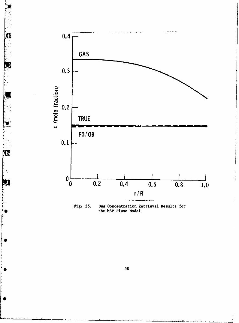
4.4 Gas Retrieval Results
For each of the three plume models, retrieval was made for gas tempera-
ture and concentration using the gas-only and first-order, off-band correct on
procedures described in Ref. 6, and the fully-coupled gas-plus-particle pro-
cedure developed here in Section 3. In the gas-only procedure, the transverse
profiles of N and T were treated as if they arose from a purely gaseous pltime
and used directly as input in a gas-only inversion. In the first-order, off-
band correction procedure, a gas-only inversion was made on the
profiles N - N and T/Tp. The results of these inversions are shown in Figs.p
24-29. The results tabled GAS are the gas-only inversion results, and the
results labeled FO/OB are those obtained with the first-order, off-band cor-
rection procedure. For the RSP model, the FO/OB results are indistinguishable
from the true profiles. The inversions were performed with the same computa-
tion conditions (e.g. lineshape and number of zones) used to generate the
transverse profiles and with the convergence criteria that the radial root-
mean-square difference between iteration results for Tg and cg should be less
than or equal to 0.1%. These inversion results duplicate the results obtained
in Ref. 6.
The results of the fully-coupled inversion are not shown explicitly in
Figs. 24-29. In all cases, the recovered radial profiles were within the
convergence criteria and are indistinguishable from the true profiles when
plotted.
56

2000
1500 *&A
F I I II
00 0.2 0.4 0.6 0.8 1.0OIR
Fig. 24. Gas Temperature Retrieval Results forthe MSP Plume Model
0'
57
0.4
GAS
0.3
0.
~0.1
0
0 0.2 0.4 0.6 0.8 1.0rIR
Fig. 25. Gas Concentration Retrieval Results forthe MSP Plume Model
* 58

~GAS
1500 -FO/IOB
500
0 I0 0.2 0.4 0.6 0.8 1.0
OIR
Fig. 26. Gas Temperature Retrieval Results for theALP Plume Model
59

10 GAS
.0
TRUE001
FO/OB
0 . . R 0.6 0.8 1.0
Fig. 27. Gas Conlcentration Retrieval Results for theALP Plumbe Model
60

2000
GAS
5000
500
0 0.2 0.4 0.6 0.8 1.0OiR
Fig. 28. Gas Temperature Retrieval Results for the* RSP Plume Model
61

0.25
.GAS
0.20
waf.15
TRU
U0010-
0.05
0 III*0 0.2 0.4 0.6 0.8 1.0
r IR
Fig. 29. Gas Concentration Retrieval Results forthe RSP Plume Model
62

5. SUMMARY AND CONCLUSIONS
In the first phase of this work (Ref. 6). and repeated here, it was shown
that even for plumes as lightly loaded with particles as the MSP and RSP
models, the effects of particles could not simply be ignored in attempting to
retrieve gas temperature and concentration from two-phase plumes. Retrieved
temperatures were invariably too low, and concentrations were too high. With
partial account of particle effects through the use of the first-order, off-
band correction procedure, retrieval for these two lightly loaded plumes was
substantially improved. For all practical purposes, the first-order correc-
tion procedure suffices as an accurate diagnostic for the gas properties of
these plumes. For the more heavily loaded ALP plume model, however, even this
correction procedure could not yield good gas retrieval results. In response
to this problem, the fully-coupled gas-plus-particle retrieval procedure
described in this report was developed. This new procedure is capable of
arbitrarily accurate gas property retrieval from ideal data.*
In addition to the improved gas property retrieval procedure, a meth-
odology for retrieving particle properties from appropriate E/A and laser A
scattering data was developed. These rocedures were also shown able to
retrieve particle properties to arbitrary accuracy from ideal data. -
In all, the results of this work demonstrate that a complete diagnostics A
procedure for retrieving both particle and gas properties from two-phase, low-
visibility propellant plumes could be developed. The fundamentals of the
procedure have been developed and tested here. Additional work must be made
A minor penalty of substantially increased computer running time is paidby using the fully coupled retrieval procedure over either the gas-onlyor first-order, off-band procedures.
63

on error propagation effects, and procedures for retrieving particle size and
spatial distributions would enhance the value of the diagnostic.
[I6
64
S.