to - defense technical information · pdf filesx,s~x,am=...
TRANSCRIPT
UNCLASSIFIED
AD NUMBER
CLASSIFICATION CHANGESTO:FROM:
LIMITATION CHANGESTO:
FROM:
AUTHORITY
THIS PAGE IS UNCLASSIFIED
ADB805398
unclassified
restricted
Approved for public release; distribution isunlimited.
Distribution authorized to DoD only;Administrative/Operational Use; MAY 1941. Otherrequests shall be referred to NationalAeronautics and Space Administration,Washington, DC. Pre-dates formal DoDdistribution statements. Treat as DoD only.
NACA list dtd 28 Sep 1945; NASA TR Serverwebsite

—,.- .—
i
No. 806 .- —- —.. -
STRESS3SA:7DDEELECT!IOESIN THIN SHELLSAND CURT3D PLATES -—
i DUE TO CONCEYTRA!rXiDAND VARIOUSLYDISiRIWJTEDLOADING*
3Y Ray=ond J. Eoark —>Universityof Wisconsin
WashingtonMay 1941 —------ —=
-.
. .. . .4
---- .... . ... ...- .,-.. —._ ___
.

kNATIONALADVISORY COMMI’T!C’EE20R AERONAUTICS
wTECHNICALNOTE NO. 806
..,,. .,
STR3SSZSA_i.iDDEFLECTIONSIN THIN SHELIISAND CURVED PLAT3S,,
DUW TO CONC3YTRATEDANI)VARIOUSLYDISTRIBUTEDLOADING,.By Raymond J. Roark “
..—
SUMMARY
Testsmade upon cylindricaland spheri’balshells to ‘- ‘“-determinethe local stressesand deflectionsproducedby ““concentratedand va%ieuslydistributedl“oadingare de-
.-
scribed. The results o: these tests are correlatedwiththose of earlier experfmeuts,and empiricalformulasbasedon these data are proposed. Data are prese-n—tedon the ef-fect of severe prestressingupon stiffri”essaridon the ef-ficacy of welded lugs df various forms in transmittinga —.load to a thin shell without producingexcessivelocal— —stresses. .,.-.
AI~J~RODU(JTION ,
,,9.
. The stressesproduced in thin shellshaving the fortiof surfacesof revdluti.onhave been an”alyzedmathematicallyfor some cases of dist??ibutedand s’ymrnetrical-loading(ref-erence 1). The solutionsare not simple,and to apply‘similarmebhods to cases’of concentratedand nonsymmetri-oal loadirigwould be difficult,if not impracticable. Itthereforeseems expedientto seek purely empirical’formu- ““‘–las that, for such cases, expresswith adequateaccur-acythe relationshipbetween the load, the dimensionsof theshell, and the stressesand deflectionsproduced;and itwas the purpose of the investigationherein reportedtomake appropriatetests and to derive therefromformu~as ofthis kind. Tests made for ~ similar purpose have “been‘de-scribed in reference2; but the ear”lierinvestigationwaslimited to cylindricalshells under concentratedloading,and the ex-pressionsderi-kedfor stress and’deflectionwere, it is believed,needlesslycumbersome.+.,
“/;hena thin shell, such as a “p’ip”e,a tank, or a mono-coque fuselage,is subjectedto localizedloading remote,. ...

2 NACA K2echhicalNote No. 806,---
...
from points of supyort,the stressesproducedmay, for.
convenience,be classifiedas (a) generalstresses,mainlymembrane stresses,due to the bridgelikeaction of theshell in transmittingthe load to the supports;and (b)local stresses,mainly bending stresses,due to the plate-like action of the loa~ed part of the shell in transmittingthe load to the structureas a whole. When the load isconcentratedon a relativelysmall port50n of the shellsurface,the stressesat even a small distancefrom thepointiof loadingbecome negligiblysmall in comparisonwith those adjacentthereto,and, for such loading,thelocal stressesalone are likely to be important. a
---
These local stresses,and the local deflectionsaswell, dependmainly uppn the thicknessand curvatureofthe shell and the magnitudeand degree of concentrationof the load and are almost independentof the general di-mensions of the shell (suchas span),provided the loadis reasonablydistant from points of support. As long,then, as these local stressesand deflectionsare substan-tially~iadependentof the deflection- that is, bear alinear relationshipto the load - it would seem that i.tshould be possible to express them approximatelyby simpleformulasinvolvingonly curvatureand thicknessof theshell wall and distancefrom the point of loading. Forthe shells tested, it was found that this llnear relation-
*
ship existedand that stressesand deflectionscould beexpressedby formulas of the kind indicated. ,s
l?he’tests and the resultsare discussedunder twoheadings: CylindricalShell and SphericalShell.
This investigation,Wisconsin,
conductedat the Universityofwas sponsoredby, and conductedwith firiancial
assistancefrom the NationalAdvisory Committeefor Aero-nauticsand the WisconsinAlumni ResearchFoundation.
NOTATION
The followingnotation is used throughout:
A area over which the load is distributed
a half length (in x direction)of a rectangularloaded area
b half width (in y direction)of a rectangularloaded area
—b
a
A
*
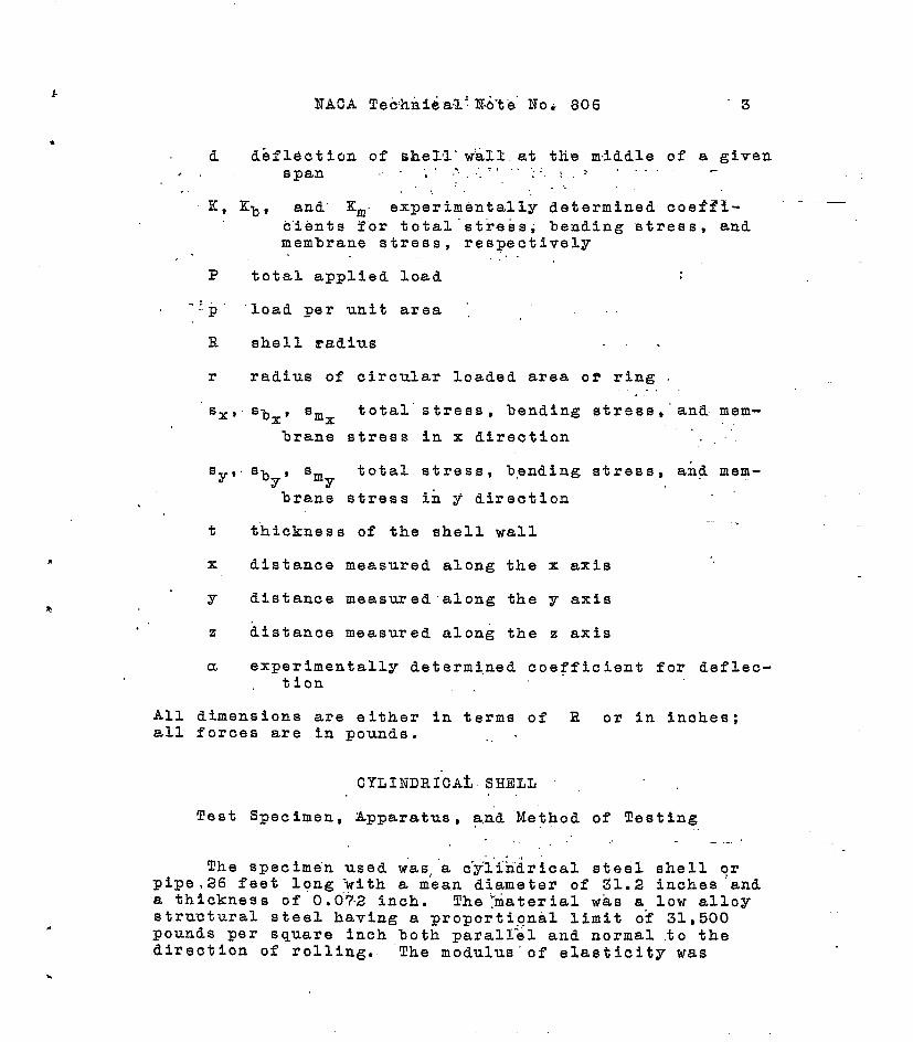
d dbfl~ctionof “she~’1.w’all.at the middle of a givenspan .. . ......,.,, :., .-. .... -.!,
...,.K, Kb, and” Km. ‘experimentallydeterminedcoeffi- ‘-—
c’ientsfor total“st”re&s;bending stress,andmembraue stress,respectively
,. ..P total applied load :
..:.“P “loadper unit area ‘, ,
R shell radius . . .
r radius of circularloaded area of ring.,.Sx, s~x, am= total’stress,bending stress,”aatlmem-
lrane stress in x direction
‘yS”‘~ 9 ‘m total stress,b,endingstress,and mem-Y Yllranestress id ~ direction
t thicknessof the shell wall-.
x distancemeasured along the x axis ‘.
Y distancemeasured’alongthe y axis
.’z distancemeasured along the z axis
a experimentallydeterminedcoefficientfor deflec-tion
All dimensionsare either in terms of R or in inches;all forces are in pounds. ..”
CYLINDRI”CAtSHELL .“,,Test Specimen,Apparatus,a,rid‘Methodof Testing
,, —.-,,,,,.,
The specimenused was,”ac“y”liridricalsteel shell orpipe,26 feet long ‘witha mean diameterof 31.2 inches anda thicknessof 0.0”?-2inch. T?he~materialwas a low alloystructuralsteel having a proportionallimit of 31,500pounds per square inch both paral~~l and normal to thedirectionof rolling. “Themodulus”ofelasticitywas

28,300,000and 27,050,000pounds per square inch parallel.
and normal to the directionof rolling,respectively* !l?hepipe had welded to each end a squarebulkhead3/16 inch thickwith a circularopeningabout 30 inches in diametertoperait access..tothe interior. Thesebulkheadsrested onsupports,as shown in figure 1, so that the shell actedas a simplebeam carryingIts own weight and the appliedloads. ,.
The shell was subjectedto outwardloads applied atthe inner surface end to inward loads applied at the outersurface. The outwardloads were applied througha sfmplelever system. A lopg timber beam, inside the shell andparallel to its axis, waspinned at ite oute~-end to one-of the bulkheads. On this beam was mounted a slidingblock that carrieda vertical loading colu?qn,and thisloading column could be p18,CSdat any desiredpOSitiOnalong the axis of th~pipe %Y sliding the block along thebeam. To the inner end of the beam was attacheda rodthat passed vertio~llydownwardthrougha small hole inthe bottom of the ,she,ll,.A.springdynamometerwas sus-pended from this r&d, and by means”of a small self-lockingwinch and chain any de,$,iredload could.beapplied thereto.This lever systemwas carefullycalibratedin advance overthe entire range.of l~ad~ng contemplated..
The inward loadingwas accomplishedby means of anordinaryautomobilescrewjackprovidedwith an adjustable sloadingcolumn and restingon an accurateplatformscale.
Strains..weremqasuredby Huggenbergertensometersad-justed for half-inchgage lengths..Detlectioiiswere meas-ured with a Federal dial readingdirectlyto 1/10000 inch,
t . .,.
Testing‘Procedureand ~esfilts
Concentratedloading.-~It.w,asdesired to determinefirst the stressprodu~edat”a give~ point, herein called‘fstatioai”bv a.concentratedload a~plzedat any.adjacent.,.point. For purposee of refdrefic”e”,a longitudinallinethrough the stationwas taken as the x axis, a circumfer-ential line as th~%y axis, and a.line a~.45C - or half-way between.fhesetwo - ‘aA”the z axis.’ ‘The positions-ofthese referenceaxes @r,e shown..infigu~e 2. Wf$hthestrain &age,,”pLaoedat,the.sta$$~n~i$heload was applie~at close intervalsalong,.aach.,of “tihqqe”.m~h-ree. axes and the *longitudinalstresses”.‘sx and the-c.ircumfe~etifialstresses
.

kNACA Technical.’.Nate”No’.806 5
.
‘Y which, because of symmetry,were known to”be the“ principalstresses,were.determinedfor eaoh such ‘positionof the loatl. Th’isprocedurewas c“ar”ri-ed-out’for each offour ,differeutstations;’“~pacedsome distanceapart alongthe bot’tomelement of the “cylinder,at distancesfrom the:~j;est point o-fsupport (the,end bulkhead)varying.from
tO ~6R. ~Within these limite‘proximityto support- appearedt’ohave no “appreciableinfluenceupon thestressesat andnear the point‘of“loading;hence the re-sults of strain measurements-at the .s,evetialstationswereaverag-ed. .’.
In the first ‘testthe load was applied progressively“insmall increments,to ascertainthe maxim-amload thatcould be”applied w:thout daager of overstressingand toascertainwhether the Ioad-stressrelationshipwas appre-ciably affectedby the deflection. This relationshipwasfound to be a linear”oneand, subsequently,the maximumload was applied directly. .’ .-
‘In order to ascert.einwhat part of the measuredstrainwas due to bending stress and what part to &embrau~ stress,simultaneousmeasurementswere,taken op “bothsides “oftheshell wall. Cirec.tlya-:‘thepointof lc-a~i-ng-,“wh~resuchreadi”ngs”couldnot be taken”$r“eadingsw~~se”take-noa theouter face with’ou*wardloading‘andon the inner face_withinward loading. The first readings repres~~cedthe sfi ofbending a’ndmembrane.stressesand the second readings,thedifferenc&;a’ndso It was possible to’de~erm~nethe valueof each kind of stress.,.I“tWaSfo~d tl~t a-t’“a&n&-arthepoint”of loadiag the rnem”~ran-&s“tre9s”was small ccmparedwith.the”bending.sfir.ess,_beingless than 10 percent of thetotal; fOr this .raasoi it. was’deci~~dth~$ the total sur-face stressat-any point could be regardeda-$a bendingstress and expressedby the formula s = KP/t2, K beingan empiricalcoefficientdepei~~ingupon the distancefromthe point.df loading.. Tae ess~e~imbntally determinedStresses;-expre&Se3.:~,nterms of K and as functions of thedistance~rorn+.he.?.cadin terns of R,. are,given by thecurves of figures E and4.
The strain measurement’sgave only the average stressover half-inchgage .lr?r~gths,and, since the variation instress intensityis ‘rs-(yrapid near the point of loadtng,:the maximum value at th&t point is cons~derably..greaterthan this average-value. lt was estimatedby Assuming that1. its ratio *6 the ave~gagestress’wasequal to the correspond-ing ratio in the case of a Centrallyloaded circularflat
,. ..●.’

6 NACA TechnicalNbte No; 806
plate having a diameter.equalto the ti..stancebetweenpoints of inflectionin the shell, This method of calcu-lation indicated ratio of maximum to average stress of1.61 in the case of,circumferentialstress and of 1.41,in the case of longitudinalstress,.In the calculationof the stressfor the hypotheticalflat plate, the con-centratedload was assumed to,be distributedover a cir-cular area of radius 0.32,5,t, in accordancewith Vfester-,gaardtsapproximateformula’forflat plates under pointloading. (See reference3:) It follows that the peaksof the“curvesof figures3 and 4 depend somewhatupon thethicknessof the shell,hut, so far as the practicalquestiono.fthe effect of a load distributedover an areaof “anyconsiderablesize is concerned the influenceoft upon K would tiequite negligi.hle,at least for rela-tively thin shells.
,,This study of the effect of purely concentratedload-
ing reproduced,to a certain extent,work done in theearlier investigationreported in reference2? and theresultsare in reasonablygood agreementwith those pre-viously obtained.
Loadin+zuniformlydistributedover a nectangnzlararea.-From the curves of figures3 and.4, the diagramsof ffgures “5 and 6 were constructed. These diagramsshow contour”lines of-influencesurfaces,for ‘T and. s=; an ordinateto one of these surfecesat any point representsthe stress ‘producedat the station x = O, y = O by a load appliedat the point ,in questloa. The sfiressproducedat X=o,Y=o by a unit load .p uniformlydistributedover anyarea A. is obviously‘ZKpdA, which is proportionaltothe volume under the influencesurfaceand within thearea A. It is thereforepossiblb,by the graphical in-tegrationof such volumes,to determiaeapproximatelythecircnmf.erentialand longitudinalstressesproduc~dby anygiven distributionof load., This procedurehas been car-ried out for the case of a load uniformlydistributedovera rectangulararea-of length 2a and width 2b. The ca~cu-lationswere limited tc areas so small that local stresses,comparativelyindependentof span and method of support,would become exceqslvebefore the generalmambrane stressesbecame important.
The results of these computationsare given in tablesI and II. The values in the upper horizontalrow (b = O)representst,ressesdue to q line load uniformlydiStribut- %ed along an element of the cylinder,the values izlthe
*Out of print. Availablefor referencein librtirles. ●

.i
.
first vertical,.co,l.ll,~n,.;(a:,y:~Q?.!.rea.?ese~~.the ~“t’~essesdue .toa line ~oa~urii.f~,rvly~.d$g!rihvtedalong a Portionof the circumference,and.+$her.valueerepresen~thestressesdue to a .l,oad..’uniforlylydi6trihutedover an areaof the indicatedlen~tha~di,widt.h~By linear interpolat-ion, the effect of a load distributedover any rectangu-lar area within the limits of the table can be found.
Tlie6e coefficientsare, of courrse,approximateandare probablymore nearly correctfor small areas than forrelativelylarge ones”. They were checkedby determiningthe stressesproduced~y a load applied.through paddedtempletsof various widths, cut t.cfit the curvaturedfthe shell and placed at various longitudinaldistancesfrom the station. The area under the s-x curve for suchloadi~g gave yalues of K correspondingto a = x andb = the half width of the loaded arc. Values of K de-terminedin this way,were ii reasonablygood agreementwith those found from the vo”lumes~nder the influencesur-faces.
Loading on a circular area and.on a circle.-By meansof circularklocks cut to fit the!.inner,surface of the.shell and thickly padded with sponge”ruhher, the maximumstressesdue to a uniform load on a circulararea weredetermined. The resultsare shown in figure ?’. In thesame way, the effect of a load uniformlydistributedalonga concentriccircle or ring was determined,and the re-sults are shown in figure 8. In the case of a circulararea the m’axim”umstresseswere found to occur at the cen-ter; in the case of a r~ng the maximum longitudinalandcircumferentialstresseswere found to occur at the endsand the sides of the ring, respectively.
,.,Loading throughwelded lugs.- The usual method of
introducinga load or a reaction into a thin shell isthrougha welded .orriveted lug or clip. There seems tobe no very definite agreementamong,me,talfabricatorsasto the best design.for such attachments..norany very def-inite informationas to the str~s.sesproducedby loadsthus applied. .Therewas,,th.erefore,little informationto go.on in design~ng.,theexperimentalforms tested inthe.present inves~igq.~ion~:,.Of the 5nf’.initevariety ofshapes and gizes thatmight ,~pused, the eight shown infi’gure:,9and the thzee addit.iona~ones describedin table111 were adopted. I,t,was,,de,sired“toascertain somethingconcerningthe effect o-flength in the case of longitudi-nal and.circumferentialplate lugs, and it was thought

8 I?ACATechnioa’1Note No. 806
that-‘thetaperedf-ormsmight, by defledting:~lightly~cause less severe stresses-atthe tips than the stifferrectangularforms. The circu~arrings representcondi-tions that might be expectedto occur“whentubularstressmembers are welded directlyto a shel”l...
All the lugs were electricallywelded to the ex’teriorof the shell and loaded izzwardly,Longitudinaland cir-cumferentialstresseswere determinedat the ends of theflat lugs and at the ends &n’dthe “sidesof the rings. Theresultsare given in table III; they are irr6gularanddoubtlessreflect the inf~uenceof distortiondue to weld-ing$ as well as the influenceof the form and.the size ofthe lugs. The welds were made with care by an experiencedoperator,and the distortionthat occurredwas probablytypicalof what might be generallyexpec’tedin thin metal.The amount of this distortionw’asmore or less proportionalto the amount of welding, and this fact appears to haveoffset in great neasure the advantagethat might have ‘beenexpectedfrom an increasein lug dimensions. Particularlywas this true in the case of the larger rings, where thedistortionW’+Svery marked arid”took the form of a flatten-ing of the shell which might be expectedto .re.dvcegX5atlY ._ ._its resistanceto inward loa”ding.
It is interestingto compare the stressesproduced *
by loads ayplied through the attachedlugs with the maxi-mum stressesthat would accompanythe applicationof equalloads uniformlydistributedalong lines or circles of cor-
.
respondinglength or size. These stresses,computedbymeans of tables I and 11 and figure 8, are thereforein-cluded in table 111,
It would be incorrectto assume that either the ex-perimentallydeterminedvalues of K for welded lugs orthe,computedvalues:of K for--lineloading are applicableto riveted lugs. h the case of a“riveted lug or member,the distortionof the shell producedby welding would beabsent and the loadingwould be distributes,not along alin,e,but aver an. area of at least sufficientwidth topermit tke-,.riv-eting opetiatlon..It is possible that thestressesproducedby the impositionof a t~rus~ througharivete:dcon.nec%,idnSou.ld%e, i.nsome instances,approxi-mately:fi.et,er.m”inedby assuming-thepressure” to be distrib-uted uniformlydver the:entire area of contactand by tak-ing.($romtable 11 or fig. 7 or 8) a value of K corre-sponding’to the shape and the.s’i.zeof that area. Butthereis usually-likelihoodof higher than average press-”
.

NACA TechnicalNote lfo.”806 9
.
ures at the edge”sand “c-orderso’fS-ucka connection,withconsequenthigh local stresses. Reliable information..concerningthe stresses to be expectedat riveted connec-tions could be secured only from tests made on the typeof lug and joint in question.
Deflection.-Xeasurementswere made of the midspandefle~ion producedby a concentratedload, relat~ye tojoints at the extremitiesof a longitudinalspan of vary-ing magnitude. Such measurementswere made in the earlierzests mentioqed,and an empiricalformulawas proposedwhich fitted the results of those tests reasonablywell.This formulawascumbersome, however; so an attemptwas,. “P Rnmade to find a simple expressionof the form d = cc—.—E ta+l’with a a coefficientdependentupon the span, that wouldfit the results of the oldqr~testsas well as the present
‘R 1.2ones. 0
The formula adopted was d = a ~ ~ , With
values‘of a as follows:
spanjll= 0.1 C.2 G.4 j:6 G.8.1.0 1.2 1.4 1.6 1.8 2,0 3.0 4.0
,ti= [email protected]().”+~0.500.590.66,.
The deflectionis due part.1.rto bending and partly to””membrane strain and the relativeamounts of strain energyaccountedfor in these two ways varies with the span andwith the deflection. Hence, it is not possible to expressaccuratelythe deflectionby a simple formula such as thatgiven except for comparativelysmall ranges of the R/tand span,iRratios. The old and new tests combinedcovered -a range of /F-t ratios from 36 to 217 and of span/Rratios up to 4. The values of u were adjusted for closeagreementwith the present tests (R/t = 217), but in nocase do the measured deflectionsfound in the earliertests (R/t = 363 and 89) differ by more than about 20percent from deflectionscomputedby the formula.
In the-testsused to determine a, the point ofloadingwas distant at least 2R from the nearest bulkhead,but proximity to support outside the span was found tohave little effect upon deflection,and the deflectionatthe middle of.a span having a bulkheadat one”or both,endscan be found appro,ximately.bythe formula given.
Effect of.initialoverloading.-It $,s the practice of

10 NAC.A!l?echni,calN.ot.eNo,.:806
some metal.fabricatorsto pro,duceby overstressingan in-itial distortionat,the placewhere.a concentratedloadis to be &.pplledtQ a plate or shell. This effect enablesthe structure.to resist subsequentloadingalmost whollyby membranestress,and t,hereis consequentlya gain fnstrengthand stiffness. In order to ascertainsomethingconcerningthe,effectivenessof thisprocedure, load-deflecti.ondiagramswere obtainedfor initialand repeatedheavy loading,both inwardlyand outwardlyapplied,theloadbeing concentratedat a point to make possiblethegreatestdegree of local overstressingw,iththe least load.The results of these tests are shown in figure 10. Y’orsubsequentloadings.(afterthe second) the load-deflectioncurve was practicallyidenticalwith that for the firstrepetition.
It’is”apparent from the load-deflectiondiagramsthatthe shell can withstand,without excessivedeformation,far more load when loaded outwardlythan when loadet in-wardly. This result is what would be expectedbecause inthe one case the doformatfonresults in a form betteradapted to mem%raneresistancewhile In the other the flat-tening of the shellhas the oppositeeffect;.It is inter-esting to note that the diagram for inward loadinghassomewhatthe same characteristicsas a load-deflectioncurve for a Bellevillespring,showinga similar temporary
.
decrease in stiffnessat a deflectionthat correspondstoa form making the membrane stressesleast effective. .
It is apparent from the diagramsof figure 10 that,if circumstancespermit initialoverloading,the abilityof the shell to resista subsequentlyapplied load can begreaily increasedthereby. .
SHPERICALSHELL
Test Specimen,Apparatus,and Method of Testing
The sp6cimenused was a s“hell.in the form of an al-most completehemisphere,“witha radius of 15 inchesanda thicknessof .0.0586inch. This shell had Welded to itsrim a stiffeningring“made“of-A2- by 21/z-by l/4-in,changle: The material was a’CEisteel having a yield pointof about’48,000“poundsper s“qtiar=“inch and “an~lt~matestrengthofL58,000pounds per square inch. The shell wasmounted on a wooden frame;th”a”tpeim~t~ed‘itto be held f~
.

.
●
NACA TechnicalNote No. 806 11
any desiredposition and was loaded~both inwardlYandou”tya”rdly,by means of th”ecolu”mnand jack apparatus thatwas used in testing the cylinder. Tigure 11 shows theshell arrangedfor:outward loading,
Strainswere measuredby means of Huggenbergerten-sometersadjusted for half-inchgage lengths. Deflec-tions were measured with a Federal dial reading directlyto 1/10000 inch.
TestingProcedureand Results
Concentratedloading.-Essentiallythe same proc~durewas followedas in the tests of the cylindricalshell.Four stations,symmetricallysituatedabout halfway be-tween the pole and the rim of the shell, were sel”ected.A meridian through any given stationwas taken as the xaxis, a great ~ircle normal theretoas the y axis, and agreat circle at 45° thereto as the z axis.’ The positionsof these referenceaxes are shown in figure 12. Strainsin the x directiondue to a 3oad applied at intervalsalong each of”the three axes were measured at each stationand, by means.of inward,and outward loading and instru-ments set on inner and outer surfaces,data were obtainedthat mate it possible to distinguishbetween bending andmembrane stresses.
The membrane stresseswere found to be of sufficientimportanceto warrant separateconsideration,and the fol-lowing formuza.was adopted for the total eurface skressat any given distancefrom the load:
.. . .
where th~ subscripts b and m refer to bendingand memb-rane stress,esand ‘t) and Km are empiricalcoefficientsdependingupon the distance-fromthe point”of loading: Theexperimentallydeterminedstressesj“expressedin terms,of‘b and ,Km’ are given by the curves o“ffigtires13 and 14.
By-the use of the same procedureas in the case Of thecylindricalshell, the bending stre”ssat the point of ioad-ing was es-timatedto be 2.39 times as gr”eat,asthe meanstress measuredover the l/2-inchgage length.,,

12 NACA Technical~ote No. 806 b
Loading on a cirbuiararea and Gn“a circle.-Fro_rnthecurves of figures 13 and “14,the contourlines of Influencesurfacesfor both s% and ‘m were constructed.;they areshown in figures 15 and 26. By the use of the methods out-lined for the cylinder,the principaletressesproducedbyany l.oaflsymmetricallydisposedabout a point can be foundfrom these diagrams. Stresseswere found for two cases:that of a load uniforhlydistributedover a concentriccirculararea and that of a load uniformlydistributedalong a concentricring. .Theresultsare given in tableIV. These resultswere checkedby direct measurementofthe stressesproducedby loadingthrough circularblocksand throughrings; pads or gasketeof sponge rubberwereused to secure as nearly as possible the assumeduniformdistributionof pressure. The agreementfound was reason-ably good.
3eflection.-Deflectionsproducedby progressivelyincreasedoutwardlyapplied concentratedloadingweremeasuredfor 4- and 8-inch spans in order to ascertainthenature of the load-deflectionrelationship. The load-deflectioncurve, shown in figure 15, indicatesa linearrelationship. The deflectionsfor an 8-inch span were al-most exactly the same as for the 4-inch span, a fact con-sistentwith the very rapid fade-outof stresses.
As in the case o~the cylinder,the relative influenceon deflectiono.fbending strainsand of membrane strainswould be expectedto vary with the R/t ratio and with thespan; with only one test specimenavailable,it was notpossible to establisha formula for deflection. Furthertests, coveringa range of R/t values,would be necessarybefore this formulacould be established.
It i.sinterestingto note that, although the sphericalshell was only about eight-tentheas thick as the cylindri-cal shell, its deflectionmeasured over a 4-inch span wasless, being 0.052 inch (for a load of 100 lb.) as against0.057 inch for,the cylinder. This result indicatesthegreater effectivenessof membrane stressesin.a shell ofdouble curvature. As in the case of the cylinder whentestedunder outward”loading,the computedmaximum stresscorrespondingto the load at which the rate of deflectionshowed an appreciablein.~reasewas”considerab-lygreater thanthe elasticlimit of the,material. Also ae in the caseof the cylinder,the deflectionincreasedat a very.slowlyincreasingrate for higher loads, and”the shell proved .
.

NACA TechnicalNote No. 806 13
capable of sustaining,without excessivedeformation,aload very much greater than that at which the deflectionrate showedan appreciableincrease,
Universityof Wisconsin,Madison,Wisconsin,December1940.
1. Timoshenko,S.: Theory of Plates and Shells. Engg.SOC. monographs,McGraw-HillBook Co., Inc. 1940.
2. Roark, R. J.: The Strengthand Stiffnessof Cylindri-cal Shells under ConcentratedLoading. ASME Trans.,Jour. Appl. Mech., vol. 2, no. 4, Dec. 1935, pp.A-147-A-152.
3. Westergaard,H. M.: Stresses in ConcretePavementsComputedby TheoreticalAnalysis. Public Roads,vol. 7, no. 2, U.S. Dept. Agric., Bur. Public~oads, April 3926, pp. 25-35.

TABLEI.-VALUESOF K FORMAXIMUMSy PRODUCEDBYA LOADUNIIHIRMLYDISTRIBUTEDOVERA RECTANGllLARAREAOFHALF-LENGTHa ANDH&LF-WIDI?Eb, CYIJINDRICALSHELL
[DimensionsintermsofshellradiusR]
x=b \
o
.025
.050
.10
.15
.20
.30
.40
.50
)
!.21
..10
.78
.48
.33
.24
.15
.096
.(s68
).05
..10
.83
.64
.43
.31
.23
.14
.09
1.10
1.78
.65
.54
.38
.28
.21
.13
.08
0.15 0.20
0.62 0.52
.53 .45
.45 .39
.34 ,so
.26 .24
●19 .18
.I.2 .11
.076 .07C
0.30 0.40
0.40 0.34
.36 .31
.33 .28
.26 .25
.20 .18
.16 .14
.094 .Oa
.057
).50
).30
.27
.25
.21
.17
.13
.07:
).60
).27
.25
.23
.15
.15
.I.2
.07C
).70
).24
.22
.20
.17
.14
.11
1.0
0.20
.19
.17
.15
.12
.10.
coom

.
TMIJ II.-TALUFISOF K FOR YA.XIKUM $x PROXJOEDBY A LOADUNIFORMLYDISTIZIWTEIl
OVERA REoTA.WJLLR MEA OT HALF-LENGTH a ANDEUF-MDTE b, CUINDRIWJ SEEIL
\
ab
o
,~f
.Ocx
.10
.15
.20
.30
.40
, .50.—
)
.,88
$.20
.87
.54
.38
.28
.17
.12
.Oal
—.—
0.05
0.82
.69
.60
.44
.33
.25
.16
.11
[D~meusionsintermnofshellradiusR]
).10
).56
.49
.44
.34
.25
.19
.U
.0%
0.16
0.44
.40
.36
.28
.22
.17
.11
.071
0.20
0.37
.34
.31
.26
.20
.16
.10
.066
).30
).30
.28
.26
.22
.18
-15
.096
.062
.—
3.40
0.25
.24
.23
.19
.16
-14
.091
.0s0
0.50
0.22
.21
.19
.17
.15
.13
.089
.059
O.EO
0.20
.19
.18
.16
,14
.12
.084
0.70
0.18
.17
.16
.14
.13
.11
.Owl
-—.
1.0
0.15
.14
.13
.12
.10
.092
.06a
=o.
mom
IJCn
J., I

NACA TechnicalNote No. 806 16
TABLE 111.- TALUES OF K FOR MAXIItiUMSTRESSESPRODUCEDBY A LOAD APPLIED THROUGHA WELDED LUG AND FORCORRESPONDINGLINE LOADING, CYLINDRICALSHELL
Type of lug Lug loading
Desig-nation
a
b
c
d
e
f
~
h
i
J
k
Description‘Y
Longitudinalplate (fig. 9)
Longitudinalplate (fig. 9)
Longitudinalplate (fig. 9)
Longitudinalplate (fig. 9)
Transverseplate (fig. 9)
Transverseplate (fig. 9)
Transverseplate (fig. 9)
Transverseplate (fig. 9)
Circularring, d5.am.,0.08R
Circularring, diam., 0.22R
Circularring, diam., 0.43R
0.37
.23
.31
.21
.24
.40
-ho
.36
.44
.45
.36
‘x
3.35
.17
.35
.29
.28
.38
.30
.29
.19
. 18
.13
Line loading
‘Y ‘~
0.75 0.54
.75 ● 54
. 39 .29
.39 .29
.45 .51
.45 .51
.14 .16
.14 .16
,50 .46
.1? .14
.06 .05

NACA TechnicalNote No. 806
TABLE IV.- VALUES OF K~ AND Km FOR MAXIMUM STRESSPRODUCEDBY A LOAD UNIFORilLYDISTRIBUTEDOVER ACIRCULAR.4REA,AND ALONG A CONCENTRICCIRCLE,
r/R
o
.01
.02
.0s
.04
.06
.08
.10
SPHERICALSHELL
;oa(ion area of radius rK~
—1.68
1.06
.70
.46
.28
.09
.03
.01
Km —
39
Z()
25
21
18
14
21
10
1’7
~oadon circle of radius r
Kb
1.68
.84
.40
.18
.12
.0?
.04
.02
Km
39
35
29
23
19
13
8
4.5

NACATechnicalNoteNo.806 Figs.1,11
A,
<
.- ..,.— .~
Figurel.-Cylindricalshellusedintest~.
Figure11.-Sphericalshellusedintests.

b
.
J
NACA Jyhnicul Note W 806 Fiqa2,3, [2
22’
/.8
L6
/4
/.2 \
#
& /.0
s08 \
04\
0.,7
-a.3 o .& .10 ./5 a .25 .30 S5.40.30.SU.W Ao. m LODwuncefm low’M mm.sd /?.
FIG.3 - Variarion of ururmferential Wess y with distance fmm paini af Icdtn measured langi-- 3“tudlnally (x), circurnferentlally (y), and al 45” (z). Cylin rlca[ shell.
:&
+
M stations m—— b pwaltd
FIG 2-Referenceaxes Forrws of cylindrical shell. Figure showsthe L@am surfc.c-ecf the shell, l%e x axis was canman to
all stations, M eud WarIan had its cwn y and z axes.
.
FIG.12- Reference axes far tests af w&ricd shell.Each station had x,y.ond z axes as shawnfor Sta. i.
.—
—
,
.._
-.

NA CA Techni CQI No Fe No. 806 Rgs. 4.9
.
4
.
.
o
1
*&a’ &
f h *9
FIG. 9 Farm and dimensions d flat lugs.All lugs#m(3t)thick.
24
..):.
●
‘o..
1.8
I
1.5-
1.4
**/.2 —~k~ /.0/j
I
0-6
0.6
04 ,x
az
o●
-0.20 .05 ./ ./5 .20 .2$ .30 .3 .& .57 .tw .i
D13faoufi Id h temmd R.W .M M
FIG. 4- Variation of Iongifudinol stressSX with dfsfanu from point of Iaadin:, measmd Iongiludlnally(x),clrcumfererrtlally(y). and d 45”(z).cy[in rlcal shell.
- .—
—

. .. .
,?
0.4
03
F
FM.5 CzmtourIlnes d lnl/
4----
MICEwrrac r W. K b SY. Cylindrical sM.
—.-. . . . .. —...- . . ——
,.
,.
.1”,,,
Q7 (28 y
m 6- ~wr IInCSof influencezurkw M cd. Km tr Cy[ind~cal droll.

2.4
2.2
2.0
1.8
1.6
1.4
ii‘2~ 1,0
i$
:aa
*
k
% Q6
c
a4
“0.2
‘o
.I,,,
\ \
Y
\
~
.0.5 .10 ./3 .20 .25 .30 .35 .4aRadii d kadtd oreo in krms d R
. .
7%
2.2
2.0
t,a.
/.6 -
! Jl\
!4
g~ L2
g
A /,0
k /-Y,,- %
~,a8.
Q6 ~
a4
&?
;: o,0 .@! Jo .15 .20 .25 .30 .35
i:1’
Radius of loaded cn+e
FIG.7- Maximum stresses due 10 Iood u i orml distributed ~ ‘, !’GW a circular ma. ?~lnd~cal shell.
FIG. 8.- Maximum streses due to Icad uniformlydktrlbuted cm a circle, Cylhsdrlcal shell.
!i
,,.,.
i, ,,,
I
I
I

.-. . .
—
—
—
—
—
—
—I ,01. .02 .ar1 Def%clw, im+es
I
FIS. IO.- Lod .Afleckm diagrams for initial (I) and repeated (z) Ioodlng.FIG. 17. - bad - deflection diagram for inilial 100ding. -=
Cylmdncal shell, concentrarad Iood, 8-inch WQn.S@erial shall’, mnmrtrakd lood,4-inch qxwr.outward Ioadirrg. a
I
iI
,,, ,, ,,

NA CA Techni cal Note Na 806 Ffgs. 13,14
45
30
-15
.?0
1.2
0.6
a4
0.2
0
-0. i
\
\
\ \
\
I I I I I I I I I ..02 .04 -m .m Jo ./3 ./4 .,% ./6 .20
D/sfuncefrombud m terms.#R
FIG. 14- Varlatlon c+ membrane stress sm. wth dlsfan~ x, Y and Zpant of loading. $herical shell.
fram
*
.02 .04 .& J2Dfston”c~ from‘l”wd m lams d“~
.16 .18
FIG. 13- Variarfan aF bending stress Sk with disrance x,y and zfram patnr of loading. .$herlcal’ shell.
.30 -..

** *
.02 .04 .ti .03x Ih ferm.s of.@
FIG.15- Contour lines of inffuemce
for sbx, Sphericol shell.
i II 1. ,,1, ,1,
Jo .12 ..4 0 .02 .04 .&$ .08 ./0 .12 .M
X ifi ferms of R
surfa03 for (xJef Kb FIG. 16- Cmtour lines OF influence surface for ~coef, Km for Smx. Sphericol ShQ II. in
(n
-G
65,,
.“,
i’ 1:,, I
;1 I i’ I,:
,, ,,, J,.. ,. ,1” l’i ml.,


RESTRICTED TITLE: Stresses and Deflections in Thin Shells and Curved Plates Due to Concentrated
and Variously Distributed Loading AUTHOR(S): Roark, R. J. ORIGINATING AGENCY: National Advisory Committee lor Aeronauitcs, Washington, D. C. PUBLISHED BY: (Same)
ATP- 8590 (None)
PVUISHINO AGENCY NO.
May '41 DOC. CUSS. Restr.
COUNT1Y
U.S. LANGUAGE
Eng. FAGS*
25 IllUHTAtlOM
photos, tables, diagra. graphs
Tests were made on cylindrical and spherical shells to determine the local stresses and deflections produced by concentrated and variously distributed loading. Results of these tests are correlated with earlier experiments, and empirical formulas based on this information are proposed. Data are also presented on the effect of severe prestressing upon stiffness and on the efficacy of welded lugs of various forms in transmitting a load to a thin shell without producing excessive local stresses.
DISTRIBUTION: Request copies of this report only from Originating Agency DIVISION: Stress Analysis and Structures (7) SECTION: Structural Theory and Analysis
Methods (2)
ATI SHEET NO.: R-7-2-32
SUBJECT HEADINGS: Cylinders - Stress analysis (28505); Structural members - Stress analysis (90859)
Air Documonti Division, Intelliganco Dopartmont Air Materiel Command
AIR TECHNICAL INDEX RESTRICTED
Wri[jht-Pattorson Air Fores Baso Dayton, Ohio J