to balun or not to balun
TRANSCRIPT
To Balun or not to Balun
You need an RF Choke / Current Balun to turn your ‘Tripole’ into a ‘Dipole’
Presented to DCARC, 2016 Oct 3
Based on: Rich Quick, W4RQ, and Kai Siwiak, KE4PT, “Does Your Antenna Need a Choke or Balun?” QST Mar 2017.
2

Some Observations
• A Current Balun is a Choke, its sole purpose is to limit Common Mode Current
• A Voltage Balun transforms impedances between balanced and unbalanced ports
• A Voltage Balun may or may not affect CMC
3

The KE4PT OCEF Dipole:Part of the Coax Radiates Intentionally
Source: QST Mar 2015
radiating extension of coax center conductor, A—B
radiating coax shield,length B—C (or B-C-D)
no radiationafter choke
4

5
Source: Rich Quick, W4RQ.
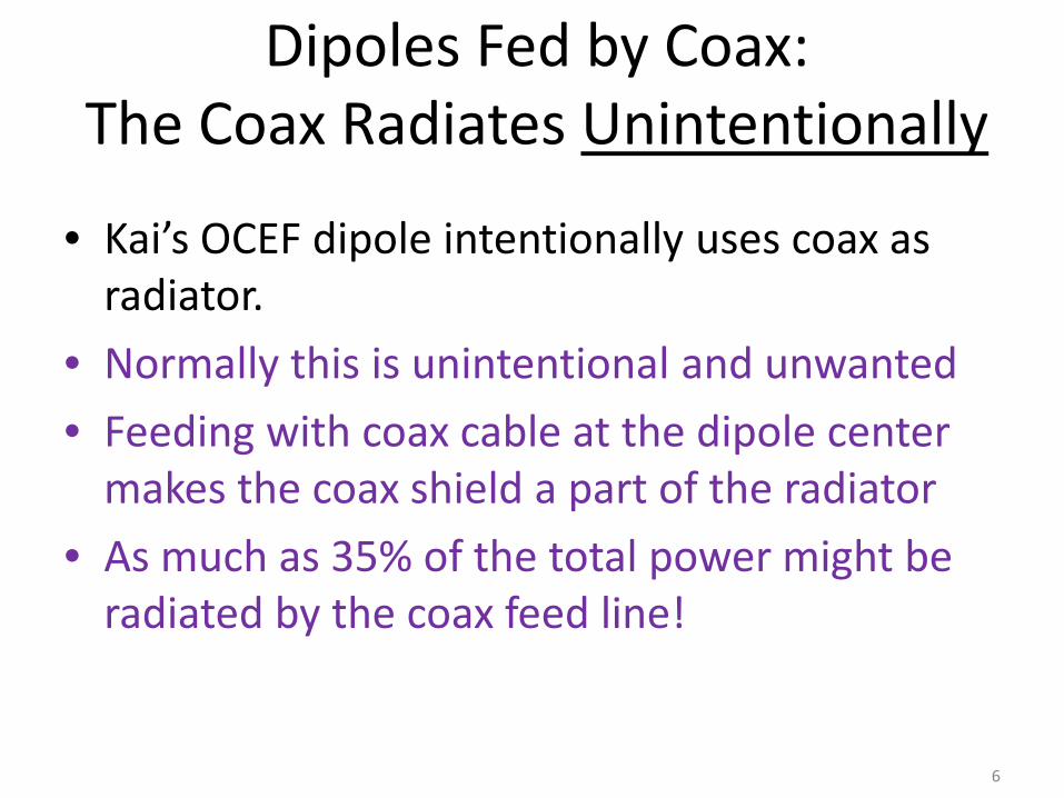
Dipoles Fed by Coax:The Coax Radiates Unintentionally
• Kai’s OCEF dipole intentionally uses coax as radiator.
• Normally this is unintentional and unwanted• Feeding with coax cable at the dipole center
makes the coax shield a part of the radiator• As much as 35% of the total power might be
radiated by the coax feed line!
6
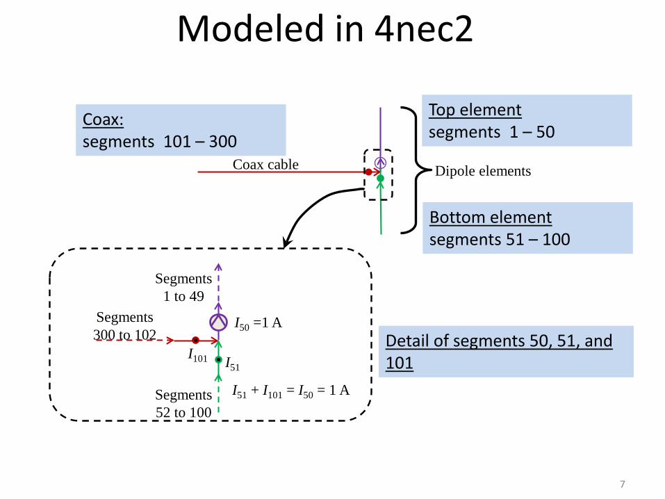
I50 =1 A
I51I101
Segments1 to 49
Segments52 to 100
Segments300 to 102 Detail of segments 50, 51, and
101I51 + I101 = I50 = 1 A
Coax cable Dipole elements
Modeled in 4nec2
7
Top element segments 1 – 50
Bottom element segments 51 – 100
Coax: segments 101 – 300

coax shield, segments 300 to 101
Common Mode Dipole(CMD)
Differential Mode Dipole(DMD)
element tied to coax center conductor, segments 1 to 50
element tied to coax shield, segments 51 to 100
current source
current source
element tied to coax center conductor, segments 1 to 50
There are Really Two Dipolesthat Share One of the Elements!
8

9
4nec2 Model of Coax-Fed Dipole Shows Currents in Wires
• 3—D pattern for dipole fed by a 2 λcoax length, or with a choke / balun at the feed point.
• Best case: Less than 2% of power radiates from the coax shield
• 3—D pattern for dipole fed by a 1.75 λ coax length, without a choke.
• Worst case: 35% of the total power radiates from the coax shield / common mode dipole.
No balun With balun
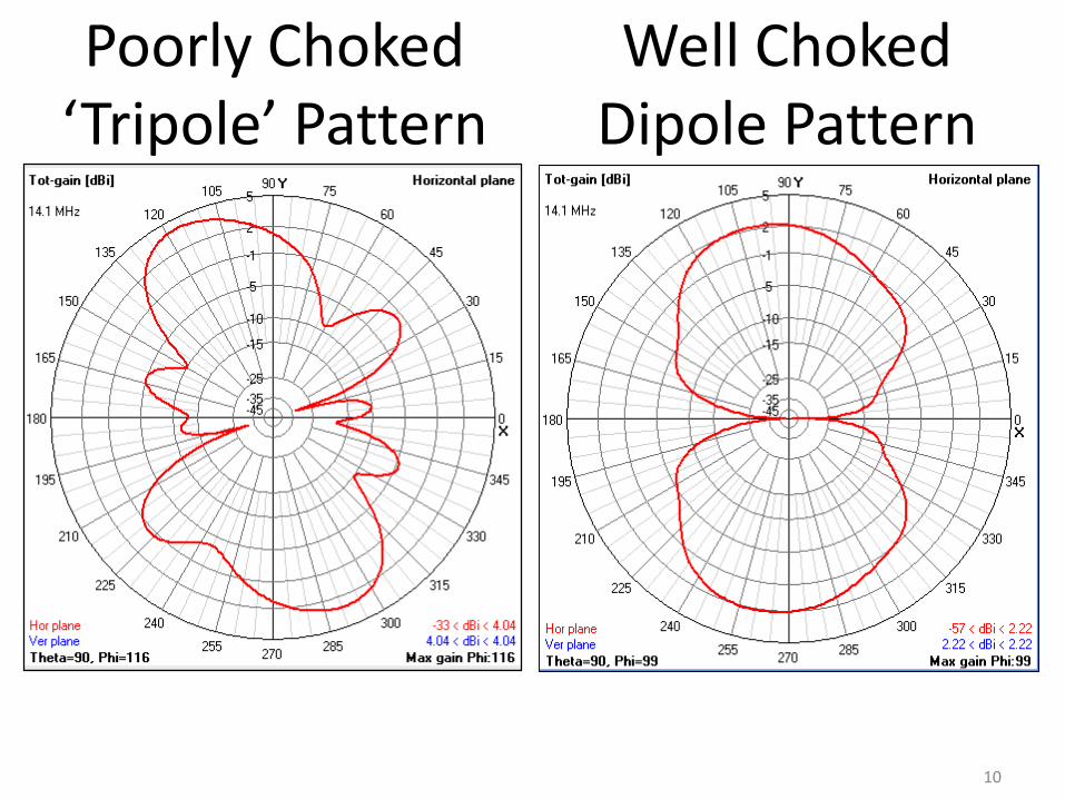
Well Choked Dipole Pattern
Poorly Choked ‘Tripole’ Pattern
10
0
0.2
0.4
0.6
0.8
1
1.2
1.6 1.7 1.8 1.9 2 2.1 2.2 2.3 2.4 2.5 2.6
Pow
er f
ract
ion
Feedline length, wavelengths
Differential mode
Common mode
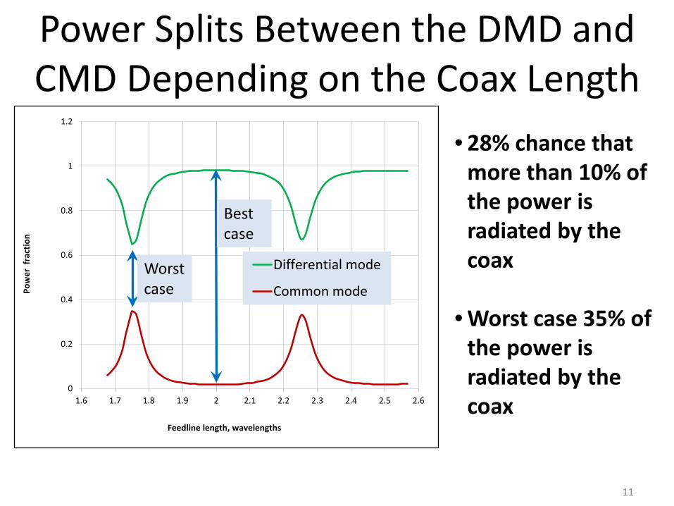
Power Splits Between the DMD and CMD Depending on the Coax Length
11
• 28% chance that more than 10% of the power is radiated by the coax
• Worst case 35% of the power is radiated by the coax
Worst case
Best case
1
1.1
1.2
1.3
1.4
1.5
1.6 1.7 1.8 1.9 2 2.1 2.2 2.3 2.4 2.5 2.6
VSW
R
Feedline length, wavelengths
VSWR(50 ohms)
VSWR(73.1 ohms)
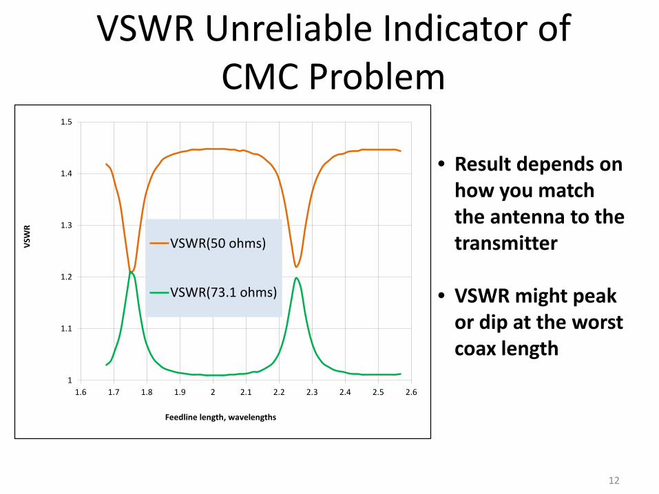
VSWR Unreliable Indicator of CMC Problem
12
• Result depends on how you match the antenna to the transmitter
• VSWR might peak or dip at the worst coax length

Do you need a choke or balun?
• No, If you don’t care about RF in the shack• No, If you don’t care about Common Mode
noise reception• No, If you don’t care about your antenna
pattern
IF YOU DO CARE: Choke the feed line
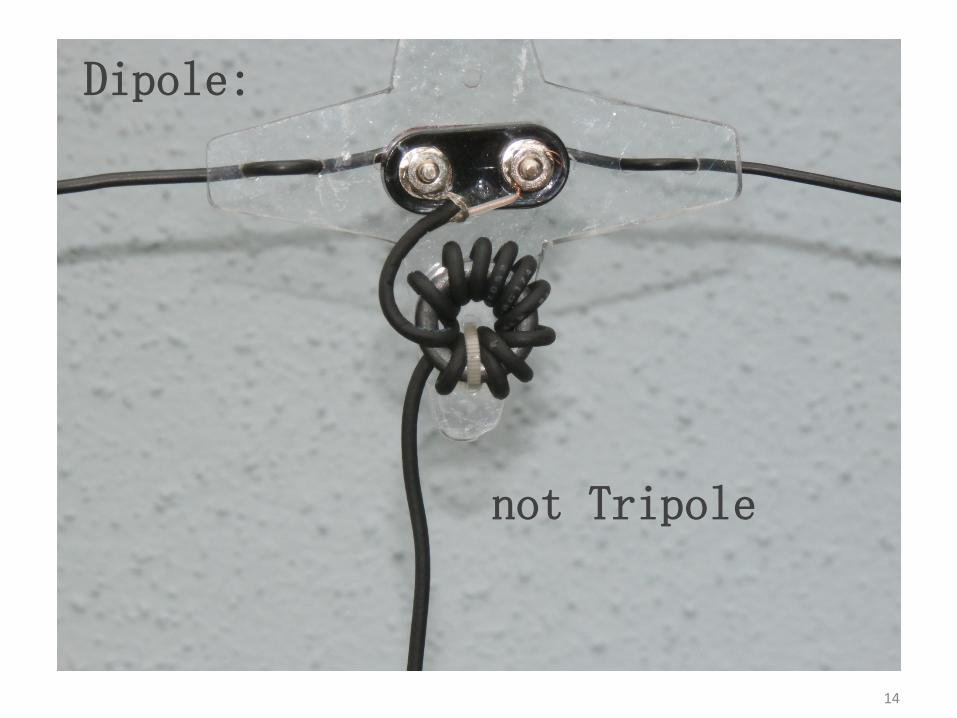
USE A DIPOLE, NOT A TRIPOLE!
13
14
Dipole:
not Tripole

15

16
Extras…

Source: QST Mar 2015
The OCEF dipole relies on radiation from the coax shield up to the chokes. You can droop it from a fiberglass tent pole that is secured to a balcony using bungee cords.
17