to advance techniques in acoustical, electrical and ... · to advance techniques in acoustical,...
TRANSCRIPT

ISS N 0007-262 1
No. 4 ~ 1 980
publ1shed quarter ly
To Advance Techniques in Acoustical , Electri cal and Mechan ical Measurement
~ Bruel & Kjcer

PREVIOUSLY ISSUED NUMBERS OF BROEL & KJA:R TECHNICAL REVIEW
3-1980 Power Based Measurements of Sound Insulation. Acoustical Measurement of Auditory Tube Opening.
2-1 980 Zoom-FFT. 1-1980 Luminance Contrast Measurement. 4-1 979 Prepolarized Condenser Microphones for Measurement Pur
poses. Impulse Analysis using a Real-Time Digital Filter Analyzer.
3-1979 The Rationale of Dynamic Balancing by Vibration Measurements. Interfacing Level Recorder Type 2306 to a Digital Computer.
2-1979 Acoustic Emission. 1-1979 The Discrete Fourier Transform and FFT Analyzers. 4-1978 Reverberation Process at Low Frequencies. 3-1 978 The Enigma of Sound Power Measurements at Low Frequen
cies. 2-1 978 The Application of the Narrow Band Spectrum Analyzer Type
2031 to the Analysis of Transient and Cyclic Phenomena. Measurement of Effective Bandwidth of Filters.
1-1978 Digital Filters and FFT Technique in Real-time Analysis. 4-1 977 General Accuracy of Sound Level Meter Measurements.
Low Impedance Microphone Calibrator and its Advantages. 3-1 977 Condenser Microphones used as Sound Sources. 2-1977 Automated Measurements of Reverberation Time using the
Digital Frequency Analyzer Type 21 31. Measurement of Elastic Modulus and Loss Factor of PVC at High Frequencies.
1-1 977 Digital Filters in Acoustic Analysis Systems. An Objective Comparison of Analog and Digital Methods of Real-Time Frequency Analysis.
4-1 976 An Easy and Accurate Method of Sound Power Measurements. Measurement of Sound Absorption of rooms using a Reference Sound Source.
3-1976 Registration of Voice Quality. Acoustic Response Measurements and Standards for MotionPicture Theatres.
2-1 976 Free-Field Response of Sound Level Meters. High Frequency Testing of Gramophone Cartridges using an Accelerometer.
1-1976 Do We Measure Damaging Noise Correctly? 4-1975 On the Measurement of Frequency Response Functions. 3-1975 On the Averaging Time of RMS Measurements (continuation).
(Continued on cover page 3)
TECHNICAL REVIEW
No.4- 1980

Contents
Selection and Use of Microphones for Engine and Aircraft Noise Measurements
by H. H. Taniguchi and G. Rasmussen . .. .. .. ......... ... ... ... ... ... ... .. 3
News from the Factory . . . . . . . . . . . . . . . . . . . . . . . . . . . . . . . . . . . . . . . . . . . . . . . . . . . . . . . . . . . . . . 31
(Front Cover Photo courtesy of Boeing Commercial Airplane Company, Seattle, WA.).

Selection and Use of Microphones for Engine and Aircraft Noise Measurements*
by
H. H. Taniguchi** and G. Rasmussen
ABSTRACT
Microphone selection and use requires an understanding of the test objectives/requirements and the acoustic environment, and the characteristics of the microphone system. This article describes a methodology and presents recommendations for the selection and use of microphones, based on situations encountered in engine and aircraft tests. The characteristics of air-condenser microphones, in a defined acoustic environment, are evaluated for their ability to meet test requirements. Microphone size, type, positioning, orientation, and calibration are considered. Specific microphone types and orientation which provide reliable measurements are recommended. The authors recognize that other microphone types may provide equivalent results.
SOMMAIRE
Le choix d'un microphone et son utilisation, exigent une connaissance et une comprehension des buts et exigences des essais et de f'environnement acoustique, ainsi que des caracteristiques du systeme microphonique. Cet article decrit une methode et presente des recommandations, basees sur les situations rencontrees Iars d'essais sur le bruit de moteurs et d'avions, pour le choix et ('utilisation de microphones. Les caracteristiques des microphones a condensateur a air, dans un environnement detini, sont evaluees pour leur capacite a satisfaire les exigences des essais. La taille, le type, le positionnement, !'orientation et l'etalonnage des microphones sont consideres. Des typeset des orientations specifiques sont recommandes. Les auteurs sont cependant conscients que d'autres types de microphones peuvent donner des resultats equivalents.
• Reprint from Sound and Vibration S)V Feb. 1979. •• Boeing Commercial Airplane Company,
Seattle, Washington.
3

ZUSAMMENFASSUNG
Zur Auswahl und Anwendung eines Mikrofons ist das Verstandnis des Prufobjekts und der Prufbedingungen sowie der Charakteristik des Mikrofonsystems notwendig. Dieser Artikel beschreibt die Methodik und gibt Empfehlungen fur die Auswahl des Mikrofons basierend auf Messungen an Maschinen und Flugzeugen. Die Eigenschaften von Luft-Kondensatormikrofonen in definierter akustischer Umgebung werden daraufhin untersucht. ob die Anforderungen der Prufung erful/t werden. Verschiedene Mikrofontypen und -orientierungen. welche zu guten Ergebnissen fuhren, werden angegeben. Die Autoren merken an, daB auch andere Mikrofontypen zu iiquivalenten Ergebnissen fUhren ki:innen.
Introduction Sound measurement and equipment standards for aircraft/engine noise testing are, in part, defined in publications of the American National Standards Institute (ANSI), the Society of Automotive Engineers (SAE), and international groups such as the International Electro-Technical Commission (IEC) and the International Organization for Standards (ISO). These publications prescribe the precision, calibration, standards and procedures for sound measurement, but do not adequately address selection and use of microphones for optimum results for specific test situations. Since microphone application influences the validity of measured noise levels, this article recommends microphone types and orientations which will produce consistent and reliable measurements for engineering development and certification testing. Using test situations typical of tests conducted by Boeing during the various phases of airplane development, the importance of microphone selection (i.e .• size, type, location and orientation) in deriving meaningful noise data is addressed.
The Federal Aviation Administration (FAA) Regulations, FAR Part 36 and the International Civil Aviation Organization (ICAO) standards, Annex 1 6, define microphone application and govern test procedures for aircraft noise certification. Sound measurement equipment specifications identified by the certificating authorities were established with the intent of providing consistent, repeatable and technically correct results, free from bias by local conditions. The application of microphones to achieve this objective is reviewed here. An alternative approach to that endorsed by the certificating authorities is recommended for airplane flyover noise measurements.
Development work prior to submitting an aircraft configuration to flight status requires sound measurements that can be related to flight conditions. This development work may include: model scale tests (static), full-scale engine tests (static). engine tests within a wind tunnel to si-
4
mulate flight effects, and airplaine flight tests. To accurately relate sound measurements from the development stages to flight certification, it is imperative that all sound pressure data be measured in, or adjusted to, an environment that is controlled or definable. Environments such as a free field, a semi-free field over a reflective ground plane, or a reverberant field, are desirable to make the measurements independent of a particular, unique, test situation.
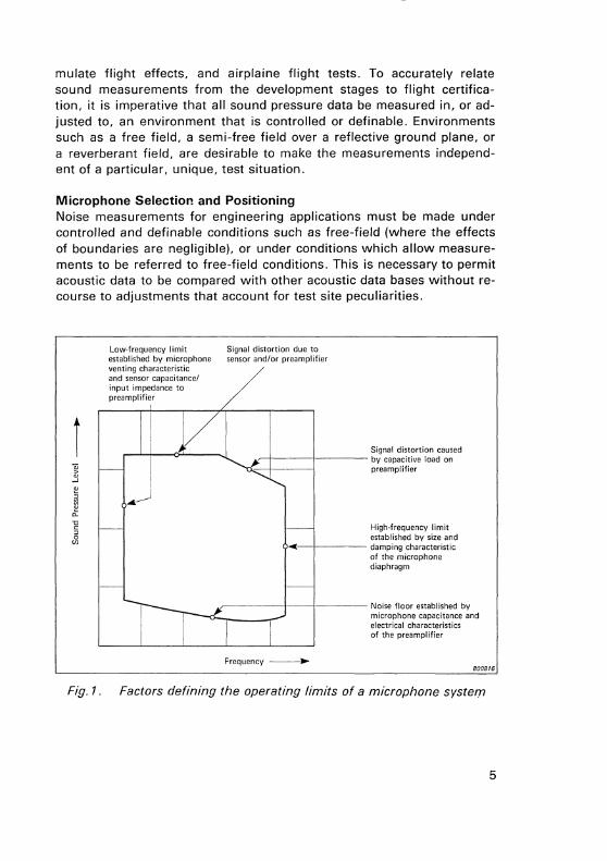
Microphone Selection and Positioning Noise measurements for engineering applications must be made under controlled and definable conditions such as free-field (where the effects of boundaries are negligible), or under conditions which allow measurements to be referred to free-field conditions. This is necessary to permit acoustic data to be compared with other acoustic data bases without recourse to adjustments that account for test site peculiarities.
i
Fig.1.
Low-frequency limit established by microphone venting characteristic and sensor capacitance/ input impedance to preamplifier
Signal distortion due to sensor and/or preamplifier
Signal distortion caused ,.....-j----j------ by capacitive load on
preamplifier
High-frequency limit established by size and
--!----- damping characteristic of the microphone diaphragm
._r------1----r---- Noise floor established by microphone capacitance and electrical characteristics of the preamplifier
Frequency ---• 800816
Factors defining the operating limits of a microphone system
5

There are several factors to be considered in the selection of the most suitable microphone system for a particular measurement situation. Aside from atmospheric and weather conditions, key test requirements in selecting microphone size, type and orientation are:
1 . The maximum amplitude (sound pressure level), the amplitude range, and the frequency range.
2. The acoustic environment. The response of a microphone to a sound field is dependent upon the location and orientation of the microphone, and the environment surrounding the sound source and microphone. The sound signal must in turn be adjusted to the particular situation by applying microphone corrections. For example, if a plane wave sound source arrives at an angle normal to the microphone diaphragm, frequency response calibration at normal incidence must also be used. Factors such as microphone directional characteristics must also be considered in selection and orientation.
The primary components of a microphone system are the sensing element (cartridge), a preamplifier and power supply, and microphone cable. Additional elements can include a protective grid cap, a windscreen, a nose cone and other special adapters. All these components, in part, determine the operating envelope of the microphone system. A generalized description of factors limiting the operational range of condenser microphone systems is illustrated in Figure 1. The detailed microphone system characteristics, including effects due to the environment, are documented in manufacturers' published literature [1-3].
In addition to the microphone characteristics outlined in Figure 1, two other factors must be considered in the microphone selection process: sensitivity and directional characteristics. Sensitivity is the ratio of the output voltage from a microphone to the input applied pressure. Generally speaking, a higher sensitivity system is desired to minimize the gain applied in the signal conditioning process, and thus reduce amplification of the electrically generated noise signal. Directional characteristics describe the response of a microphone when sound waves arrive at different angles of incidence with respect to the microphone axis. In some test situations, the directional characteristics must be evaluated for constructive or destructive interference of the direct and reflected signals in order to obtain desired results. In other test cases, the reflected signal must be attenuated by employing directional microphones. These factors, as they relate to engine and airplane noise testing, are discussed in the following sections.
6

Two classes of condenser microphones are currently in widespread use for precision noise measurement. For the purpose of this article, they will be referred to as Type G and Type N microphones. Type G microphones are designed for uniform frequency response characteristics under pressure response conditions.* These microphones have near-uniform frequency response characteristics for random incidence and grazing incidence (90°) conditions. Type N microphones are designed to achieve near uniform frequency response at normal incidence (0°) conditions. (The direction of sound travel with respect to the microphone axis defines the angle of incidence.)
~ --' 100 ~
~ ~
0..
'0
5 0
(1)
rr=======~~~l ~~~====~~ ----n---u- -.U.-- -1 0-t---- 1/8 in -n----u-------. I
u I I L -j---1/4in
--
I I '( I ?-i- -1---1/2 in
1 I I t-~-~- -1----1 in
I
Noise floor approximately 1/3·octave band level
OL---~-----L---L-------L-------'-~
100 101 102 103 104
Frequency (Hz)
Fig.2. Approximate operating envelope of Type G microphones
800817
• Pressure response conditions exist when the entire microphone diaphragm is excited with a uniform pressure, such as in cases where the microphone is mounted flush to an infinite baffle. The microphone response, mounted in this configuration, is independent of the sound incidence angle except in cases where the direction of sound travel approaches the condition where it is parallel to the plane of the baffle and diaphragm and when the microphone diameter is a significant fraction of the sound wavelength.
7

The approximate operating envelopes of several commercially available Type G microphones/pre-amplifiers are shown in Figure 2. These limits are established for pressure response and approximate the envelope for grazing incidence response. As illustrated in Figure 2, it can generally be stated that as the microphone size is reduced: ( 1) the upper frequency limit is extended, (2) the upper noise level limit is increased, and (3) the lower measurement limits (noise floor) is increased.
The approximate operating envelopes of commercially available Type N microphones/pre-amplifiers are shown in Figure 3. The frequency response characteristics of Type N microphones are most uniform at normal incidence (or 0° incidence). and the microphone should be used principally in this mode.
200.------.------,-----~-------.-----.~
150
50
-----n--11
---..fl.--u--1' iJ
-----~
-----~ I I I I I I I
-------1/4 in
I 9- - -------1/2 in
I I b-1-- - --------1 in I I I I I I
0~----~------L-----~-------L----~~
100 101 102 104
Frequency (Hz)
105
Fig.3. Approximate operating envelope of Type N microphones
800818
Many different test facility and microphone installation configurations are currently used for noise test applications. For example, model scale jet engine tests can be conducted in any of the following situations:
8

II Within an anechoic chamber in a free-field environment. II At an outdoor test facility, with an acoustically reflective ground
plane between the source and the microphone. Far-field microphones are normally positioned flush with the surface or elevated to the jet center I i ne.
II At an outdoor test facility, with a partially reflective ground surface between the source and the microphones. Far-field microphones are generally elevated to the jet centerline.
It is not the intent of this article to recommend specific acoustic environments for testing or to recommend procedures for converting measured results to free field conditions. However, one purpose is to recommend appropriate microphone types and orientations based on specific test objectives and acoustic environments. The engineering development environments selected for discussion are based on Boeing's experience in converting measured results to free-field conditions. Microphone application discussions for noise certification are based on the test measurement environment specified in Ref. [4].
Model Scale Engine Testing Model scale engine tests can be conducted either in an acoustically controlled chamber or at an outdoor test facility. An anechoic chamber is preferred since atmospheric conditions can be controlled, an all-weather test capability exists, external noise sources are excluded, and noise intrusion into adjacent properties is minimal. Weather (wind, rain and variations in temperature and humidity) experienced during outdoor tests can significantly affect the signal level and cause data spread. Measurements within an anechoic chamber provide results in terms of free-field conditions. These results can be directly translated to full-scale, freefield conditions using existing noise-scaling procedures.
Model scale engines generally range from 1/2 to 1/8 scale. The smallest scale, usually 1 /8th, generally imposes the most stringent requirement for high frequency measurements. In model testing, the sound frequency usually varies in inverse proportion to the scale factor of the model: 1 /8 scale models require measurements to approximately 80kHz as compared to 10kHz for full-scale engines. The approximate noise level and frequency limits for "near-field" and "far-field" acoustic conditions are illustrated in Figure 4.
For far-field noise measurements in an anechoic chamber, calibrated Type G and Type N microphones will measure identical levels. The operating envelopes for the three microphone systems are superimposed in
9

0 100 101 102 103
Frequency (Hz) 800819
Fig.4. Approximate noise range and model scale engine operating envelope of 1 I 4- and 1 I 8-inch microphones
Figure 4. The 1 /8-inch microphone has been excluded from far-field measurements because of high noise floor characteristics. The Type N microphones, with uniform frequency response characteristics at normal incidence, are designed for free-field test applications [5, 6]. Their principal axis is the most sensitive axis and is best protected against error due to reflection additions. Typical frequency response characteristics of 1 I 4-inch Type N microphones at 0° incidence and Type G microphones at goo incidence are shown in Figure 5. The most uniform frequency response to 80kHz occurs with Type N microphones, without grid caps, at 0° incidence. Because of this characteristic, Type N microphones in this configuration are recommended for far-field measurements. The microphone axis should be directed to the noise source.
For measurements in the near-field (but outside the turbulent wake), the orientation of a microphone must take into account the fact that jet noise is distributed along the jet axis. The source location is a function of nozzle geometry and gas operating conditions and varies with frequency. When Type G microphones are placed in the near-field and orientated with the microphone axis positioned vertically and the jet axis in the horizontal plane, a grazing incidence (or goo) situation exists for
10

Type N Microphone Type G Microphone
+10 +10 0-deg incidence with grid cap
90-deg with grid cap o; I o;
"' +5 t +5 I u .c w -~ 2
0 2 0 o; I
~ ~ I _)
-5 - I \ w ' _)
> 0-deg incidence without grid cap w
~ I >
w -10 ----- --~ -10
0: o; 0:
-15 -15 2 10 100 200 2 10 100 200
Frequency (kHz) Frequency (kHz) 800820
Fig. 5. Typical frequency response characteristics of 1 I 4-inch microphone
all distributed sources. The measured level is a function of the source level and the distance to the microphone. Type N microphones normally used at 0° incidence (directed to the sound source) are not suited for this application since the noise source location is undefined. The operating envelopes for both the 1 18-inch and 1 I 4-inch Type G microphones and the expected near-field noise levels are shown in Figure 4. Either 1 I 4-inch or 118-inch Type G microphones can be used. The 1 I 4-inch microphones without grid caps are recommended for near-field measurement if the upper frequency limit in the order of 50 kHz is acceptable. If the upper frequency requirement extends beyond 50 kHz, 118-inch, Type G microphones are recommended.
Full Scale Engine Testing Full scale engine test facilities with smooth, round river rock covering the ground plane between the engine and microphones have been used by Boeing and others. In this test environment. noise measurements are generally made in the far-field at engine centerline height. This test configuration was selected because: ( 1) the uneven rock surface provided a complex sound reflection pattern and added "randomness" to the signal to minimize sound reinforcement/cancellation patterns, and (2) ground surface impedance is changed minimally by seasonal weather variations. This test environment has been determined to be adequate in defining the noise level differences (delta increment) between test configurations. It has more recently been determined that an acoustically-reflective, smooth surface between the engine and microphones provides an improved capability for measurement and conversion to free-field levels. A concrete surface assures virtually perfect reflections which can be used constructively and provides a controlled
1 1

200
o;
"' u ID
::s NE 150
~ z "-
0 N
e ~ 100 3 1' a ~
ll.
"0 § 0 50 <n
0
~--,
f---h ---- -n-------- ll 11 U f- --fl- --o--1-1_1_1_ -- -1 in (type G,N)
.-------;" ~----, I I I I I 1 I II I o __ -~-1-1-1- _Far-field I I 1 I levels
I : I l1 --1 I Ill
I 1 I bL --1/4 in !type G,NI I I I IT 1 1 ?-LI- -1/2 in (type N)
;, II I ~-1-l/- -- 1/2 in (Type G)
---1 I v L_ f-..;--- I -- I I -----{J_ ___ )/
105
Frequency (Hz) 800821
Fig. 6. Approximate noise range and full-scale engine operating envelope of 1/2- and 1/4-inch microphones
acoustic environment to accurately translate measured results to freefield conditions. The expected far-field noise levels and frequency range for full-scale engine noise are shown in Figure 6. The higher noise levels expected from full-scale engines border on the distortion region for 1 -inch microphone systems which are therefore not considered for this measurement. As shown in Figure 6, either 1 /2-inch or 1 /4-inch microphones can be used for measuring within the defined region. Generally speaking, microphone systems with higher sensitivity ( 1 /2-inch microphones in this case) are desirable since less amplification is required during the signal conditioning process. Less amplification for measuring a given sound level often results in preserving a greater signal-to-noise ratio. Therefore, the 1 /2-inch microphone characteristics best meet measurement requirements.
A method used by some experimenters for characterizing far-field noise is to position microphones well above the reflective surface, frequently at engine centerline height, resulting in a sound interference pattern. This effect produced by the reflecting plane is defined as a function of frequency, source/receiver separation and height above ground
12
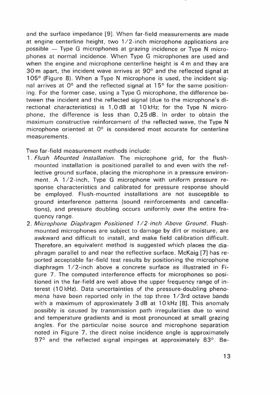
and the surface impedance [9]. When far-field measurements are made at engine centerline height, two 1 /2-inch microphone applications are possible - Type G microphones at grazing incidence or Type N microphones at normal incidence. When Type G microphones are used and when the engine and microphone centerline height is 4 m and they are 30m apart, the incident wave arrives at 90° and the reflected signal at 1 05° (Figure 8). When a Type N microphone is used, the incident signal arrives at 0° and the reflected signal at 1 5° for the same positioning. For the former case, using a Type G microphone, the difference between the incident and the reflected signal (due to the microphone's directional characteristics) is 1 ,0 dB at 10kHz; for the Type N microphone, the difference is less than 0,25dB. In order to obtain the maximum constructive reinforcement of the reflected wave, the Type N microphone oriented at 0° is considered most accurate for centerline measurements.
Two far-field measurement methods include: 1. Flush Mounted Installation. The microphone grid, for the flush
mounted installation is positioned parallel to and even with the reflective ground surface, placing the microphone in a pressure environment. A 1 /2-inch, Type G microphone with uniform pressure response characteristics and calibrated for pressure response should be employed. Flush-mounted installations are not susceptible to ground interference patterns (sound reinforcements and cancellations), and pressure doubling occurs uniformly over the entire frequency range.
2. Microphone Diaphragm Positioned 1 I 2-inch Above Ground. Flushmounted microphones are subject to damage by dirt or moisture, are awkward and difficult to install, and make field calibration difficult. Therefore, an equivalent method is suggested which places the diaphragm parallel to and near the reflective surface. McKaig [7] has reported acceptable far-field test results by positioning the microphone diaphragm 1 /2-inch above a concrete surface as illustrated in Figure 7. The computed interference effects for microphones so positioned in the far-field are well above the upper frequency range of interest (10kHz). Data ·uncertainties of the pressure-doubling phenomena have been reported only in the top three 1 /3rd octave bands with a maximum of approximately 3 dB at 10kHz [8]. This anomaly possibly is caused by transmission path irregularities due to wind and temperature gradients and is most pronounced at small grazing angles. For the particular noise source and microphone separation noted in Figure 7, the direct noise incidence angle is approximately 97° and the reflected signal impinges at approximately 83°. Be-
13
Noise Source
1 Q .. ~-----
4m Microphone
.... _:~
1/2 in
1 ----------l
l" 7 7 <r f //
30m Jloi 800822
Fig. 7. Ground microphone installation
14

cause of the near grazing incidence of the direct and reflected signals, Type G microphones calibrated at 90° response (average value between 97° and 83°) are recommended.
0 deg
to,, sode/~ t_ I ~ 105deg I
0/: >' ~///////:. ~~-- ·30m--......:
Type G
0~------------~-t
-6,0
-8,0 L-J___J~-L.....-'---"--'---.l_-...J
---.-1/4 dB
1,0 dB
0 15 30 60 90105120 150 180
Angle of incidence (degrees) 800823
Fig.B. Microphone response to the direct and reflected signals at 10kHz
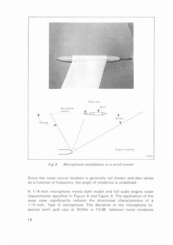
Engine Testing Within A Wind Tunnel Engine noise measurements are made within a wind tunnel to define flight effects on jet nozzle configurations. Tests are conducted in facilities such as the Boeing 9 x 9 (ft.) and NASA/ Ames 40 x 80 (ft.) wind tunnels. Tests are conducted at varying engine cycles, and at wind speeds up to approximately 90 m/sec. Measurements are often restricted to near-field, due to the confines of the tunnel walls. When measurements are made in the near-field, the measurement location must be selected so that the signal reflected from the tunnel walls will have minimal influence on measured levels. This controlled, free-field environment is necessary to define adequately engine noise characteristics.
Dynamic pressure measurements within the flow environment must be made by attaching an aerodynamically shaped object (nose cone) to the microphone to minimize turbulence noise (Figure 9). Measurements are made with the microphone axis parallel to the jet flow. For measurements made along a constant sideline distance, the angle of incidence changes as a function of fore and aft movement of the microphone.
15
Microphone traverse
I
I I
I ~ -
I I
I
Nose cone
/ Strut
!~•-._.__,._.J-1> I
+ 30 deg
Engine centerline
Fig. 9 . Microphone installation in a wind tunnel
800824
Since the noise source location is generally not known and also varies as a function of frequency, the angle of incidence is undefined .
A 1 / 4 - inch microphone meets both model and full scale engine noise requirements specified in Figure 4 and Figure 6 . The application of the nose cone significantly reduces the directional characteristics of a 1 I 4 -inch, Type G microphone . The deviation in the microphone response (with grid cap) at 40kHz is 1 3 dB, between noise incidence
1 6

BrUcl & Kjror Measuring Object.___ BrUcl & Kjrer DDDDDDDDDDDODODDDDDDDDDDODODDOOOOODODDDOOODOOODDO[
~B Recording No.: Sign.: Date: Poterotiometer: Zero level: D A B C lin
E Microphone IJo 4135 with ~ Nose Cone 1:::::: UA 0385
Hz 5 10 20
QP 1 143 Pot. Range: dB Rectifier
5 dB
Sensitivity Limits for any Incidence
Random Incidence
200 500 1000 5000 10000 20000 50000 100000
lower lim Freq · Hz Writing Speed: mmlscc. Paper Speed mm/sec. 140688
Fig. 10. Frequency response characteristics of a microphone with nose cone
angles ranging from 30° to 1 20°. The application of the nose cone reduces this range to less than 1 dB. Random incidence response calibration (falling within the 30° to 120° incidence response range) is recommended, (Figure 1 0). If more precise corrections are required, an assessment of the source location and an accurate determination of the directional characteristics of the microphone system should be made.
Aircraft Flyover Testing (Engineering Applications) Flyover measurements for engineering applications are generally made under controlled acoustic conditions in order to relate results to a freefield environment. Measurements to characterize aircraft flyover noise are made directly under the flight path (centerline measurements). Sideline measurements are not considered since reliable, accurate assessment of this noise is currently not possible [1 0]. This problem is partly related to the lack of a controlled uniform, homogeneous ground surface of sufficient area in test situations.
Measurements of flyover noise should be made over a reflecting surface of sufficient area to simulate an infinite baffle. Minimum dimensions to achieve these conditions are not known; however, measurements made over runways have been considered adequate for centerline measurements. Limited studies of surface mounted microphones have included: a microphone flush mounted at the center of a plywood panel; a microphone mounted over a reflective surface with its axis par-
17
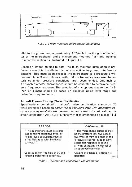
Preamplifier 7,6 m radius Adapter Cartridge
e2'------r-------1;rr---, ----------'-\ :frn "" 800825
Fig. 11. Flush-mounted microphone installation
allel to the ground and approximately 1 /2-inch from the ground to center of the microphone; and a microphone mounted flush and installed in a convex section as illustrated in Figure 11.
Based on limited studies to date, the flush mounted installation is preferred since this installation is not susceptible to ground interference patterns. This installation exposes the microphone to a pressure environment. Type G microphones, with uniform frequency response characteristics under pressure conditions, are recommended. One-inch or 1 /2-inch diameter microphones should be calibrated to determine pressure frequency response. The selection of microphone size (either 1/2-inch or 1-inch) should be based on expected noise level range and noise floor requirements.
Aircraft Flyover Testing (Noise Certification) Specifications contained in aircraft noise certification standards [4] were developed. based on objectives of acquiring data with maximum accuracy and repeatability from test-to-test and site-to-site. Aircraft certification standards (FAR 36), [11]. specify that microphones be placed "1 ,2
FAR 36-9 ICAO-Annex 16
"The microphone must be a pres- " The microphone cartridge shall sure sensitive capacitive type, or be the pressure sensitive capaci-its approved equivalent, such as tive type. It may be either of the a free field type with incidence 'pressure response' type (having corrector." a near-flat response to sound
arriving at grazing incidence) or an approved equivalent."
Calibration for free-field at 90 deg Grazing incidence orientation is (grazing if'lcidence is specified). specified. 8006&3
Table 1. Microphone application requirements
18

meters above ground level" and "surrounded by relatively flat terrain having no excessive sound absorption characteristics, such as might be caused by thick, matted, or tall grass, shrubs or matted area". Measurements must be made under the flight path (centerline measurements) and at sideline locations. Requirements related to microphone type, orientation and calibration are summarized in Table 1. These specifications and other microphone specifications [11] appear very restrictive to a particular type of microphone. However, it is expected that an "equivalent" microphone will be approved based on technical factors, such as: ( 1) dynamic range, (2) sensitivity to low noise levels, and (3) ability to provide repeatable test results (from test-to-test and site-to-site).
A wide dynamic range system is necessary to cover adequately the maximum-to-minimum sound pressures encountered in aircraft flyover noise. At the lower end of the measurement scale, overall levels in the order of 90 dB re: 20 pN/m 2 can be experienced during peak noise conditions. An additional 1 0 dB (minimum) is required to measure the noise time history for EPNL calculations. Current test situations require the capability to measure 1 /3rd octave levels (in the higher frequency
200
o;
"' u
" ::s 150 NE
z "-
0 N
1!
00 ] 100
_j
1:!
~ ci: "C ~
50 " 0 Vl
0 100
I I
I I
rffu--=&=-JJ; _:·L£l i! I II I 11 I II II
1/2 in (Type G. 4134)
- - --- 1 in (Type NJ
1/2 in (Type G. 4166)
I 1 I I :1 I I I I
11 Noise
I I I o- --1 - ~-- -- Level Range
I I I I 11 I II I II I I I I II
~-!-:::------=:-.:-- --I ~ -- --~ - -[h - _.-1 J
---{]- -101 104 105
Frequency (Hz) 800826
Fig. 12. Approximate noise range and aircraft flyover operating envelope of 112- and 1-inch microphones
1 9

range) on the order of 20 dB re: 20 pN/m 2 at 1 kHz in order to describe precisely the noise signature. Even lower levels are necessary at 1 /3rd octave bands above 1 kHz {Figure 1 2). Current noise rules define maximum permitted noise levels of approximately 90 EPNdB in certain situations. This level translates into overall sound pressure levels ranging from 80 to 90 dB re: 20 pN/m 2 .
These low signal levels require a sensitive microphone system with low self noise characteristics. Based on Boeing's experience with microphone systems with long cable lines, the noise floor {self-noise) for a 1-inch microphone system is approximately 1 6 dB lower than for a 1/2-inch microphone system. The equivalent 1 /3rd octave noise floor level {at 1 kHz) for 1 -inch microphones is 9 dB re: 20 pN/m 2 as compared with 25 dB for 1 /2-inch microphones. As illustrated in Figure 12, 1-inch microphones more adequately meet the low noise level measurement requirements than do 1 /2-inch microphones.
Based on FAA and ICAO microphone positioning and environmental requirements, measurements cannot be related accurately to an acoustically controlled environment. The measured acoustic signal is affected by the incident and reflected signals, and the interference pattern is a function of the ground surface impedance [9]. Measurements cannot, under current procedures, be referenced to free-field conditions. If however, microphones must be placed 1 ,2m above ground, free-field conditions should be approximated by minimizing contributions of the ground reflected signals. This is necessary in order to provide measurements that are consistent when tests are conducted at different test locations.· Data repeatability, from test-to-test and site-to-site, is required to assess aircraft noise.
One approach in minimizing ground reflection effects is to select a type of directional microphone and orient it to attenuate the reflected signals. The directional characteristics of 1-inch Type N microphones are shown in Figure 13. This microphone, without grid cap, meets requirements specified in IEC-179 [1 2]. For measurements made directly under the flight path {centerline measurements), the microphone placed with its axis perpendicular to the ground will minimize the effects of the reflected signal. Microphone corrections to compensate for the change in frequency response characteristics for different angles of incidence should be applied. This process can easily be accomplished by applying corrections to each 1 /2-second, 1 /3rd octave band noise value based on calculations of noise incidence angles.
20

~ Flight Path ~ ---------.
800827
Fig. 13. Directional characteristics of a 1-inch Type N microphone
For sideline measurements, the microphone axis must be directed to the aircraft and perpendicular to the flight path (Figure 14). This configuration employing 1-inch Type N microphones minimizes the ground reflection effects. When the direct signal arrives at 0° incidence, the reflected signal for the specific case noted arrives at 70° incidence. The reflected signal is attentuated by 5,5 dB at 10kHz. If grazing incidence microphones (Type G) are used, the reflected signal impinges at 1 60° and the resultant rejection is 3,5 dB (Figure 1 3). Thus it can be seen that greater rejection of the reflected signal is obtained by using Type N microphones at normal incidence. Angular corrections must be applied as noted for centerline measurements to compensate for microphone directional characteristics.
0
I .........
~ -------.
o; I .0
__:j.dB
17 ·g :s -5.0
"' ~~- --
'"'m." ~
"' "' __j > -10.0 I I Odeg 4ft ~ '---o;
3.5 dB i . 70d~ 0::
~/////~'////~ .:1 /_; -15,00 30 70 90 120 160180
---460m Angle of incidence (degrees) 800828
Fig. 14. Microphone response to the direct and reflected signals at 10kHz
21

The principal axis used with Type N microphones is normal incidence (0°), which is also the most sensitive axis, and is thus best protected against errors due to reflection additions. Type G microphones used at grazing incidence (90°) have other axes which are more sensitive. For example, the amplification relative to 90° response for 1-inch microphones at 0° incidence (at 10kHz) is 8 dB; the 1 /2-inch microphone amplification is 4,5 dB. This characteristic, coupled with possible multiple reflective sound paths (buildings, ground contour effects, trees, etc.), can cause noise amplification and erroneous levels in field test situations.
When microphones are positioned in a free-field environment, application of free-field corrections to the calibration of pressure frequency response is appropriate. Placing the same microphone 1 ,2m above a ground surface significantly alters the response characteristics. Microphone system response (including the environment) is related to source height, distance from the source and ground surface impedence [9]. The characteristics of 1-inch microphones used at 0° incidence reduce the influence of reflected signals and effectively approach free-field conditions at frequencies with large back-rejection. The application of freefield corrections (at the higher frequencies) becomes more valid as free-field conditions are approached.
Summary comments regarding 1-inch, Type N microphones and two 1 /2-inch, Type G microphones are outlined in Table 2, along with a relative "acceptability" assessment for each. This assessment shows that 1-inch, Type N microphones are most appropriate for measurements at 1 ,2m above ground level.
Based on the above discussions, it is recommended that: II One-inch, Type N microphones be used for measurements directly
under the flight path with the microphone axis positioned perpendicular to the ground (0° incidence occurs at the aircraft overhead position).
II One-inch, Type N microphones be used for sideline noise measurements with the microphone axis directed to the aircraft and perpendicular to the flight path.
22

Relative acceptability scale
Requirement Low High
Microphone 1-in type N at normal incidence
quality/stability 1 /2-in type G at grazing incidence (4134)
1 /2-in type G at grazing incidence (4166)
Sound level and 1-in type N I
frequency range 1/2-in type G (4134) I 1 /2-in type G (4166) I
Data reliability/ 1-in type N I repeatabi I ity (reducing in- 1/2-in type G (4134) I fluence of reflec-
1 /2-in type G (4166) I ted signal)
Applicability of 1-in type N I
free-field micro- 1/2-in type G (4134) J phone calibration 1/2-in type G (4166) I
Minimal influ- 1-in type N ence from off- 1/2-in type G (4134) J axis, extrane-ous signals 1/2-in type G (4166) J
800684 -----
Table 2. Summary comments - microphones used for noise certification
Aircraft Noise Monitoring Aircraft noise is measured during departure and approach conditions at numerous airports around the world to define noise exposure in adjacent community areas and to compare levels of individual events. These measurements must be made with microphone systems designed to withstand severe weather conditions, and which can be left unattended for long periods without being damaged by weather. Such a system is shown in Figure 15. This particular system is equipped with a remote controlled noise calibration device (an electrostatic calibrator). Weather protective devices, including raincovers and windshields, have been developed for use with precision condenser microphones and do not degrade acoustic characteristics.
23

Ftg. 15. Outdoor monitoring of aircraft noise
Microphones are generally installed near the community boundaries around the airport and in many instances are distant from the airplane flight path. This variation in microphone placement coupled with variability in flight procedures results in wide variations in the noise incidence angle to the microphone. Thus, it is desirable to use an omnidirectional microphone to ensure that measurements are independent of microphone directional characteristics. Microphone dimensions must be small for the microphone to approach omnidirectional response. This small size normally results in reduced sensitivity and an increased noise floor. The aircraft noise level range of interest is from approximately 60 to 1 00 dBA. In addition to aircraft noise, it is desirable to measure the ambient or background noise to characterize overall community noise exposure . Ambient noise ranges from approximately 20 to 60 dBA. A 1 / 2 - inch microphone represents a suitable compromise for measurements in the 20 to 1 00 dBA range and when omnidirectional response must be preserved.
24

When the aircraft flight path is directly or nearly overhead, the axis of the microphone should be perpendicular to the ground. This configuration results in minimal influence of the microphone's directional characteristics on measured noise levels. It is assumed that in most noise monitoring measurements the significant noise impingement occurs within 60° of the perpendicular microphone axis. The deviation in response between 0° and 60° for a particular 1 /2-inch microphone is approximately 2 dB at 10kHz. If the microphone were oriented with the axis parallel to the ground, the noise impingement angle is from 30° and 150°. The deviation in response between 30° and 150°, for the 1/2-inch microphone, is approximately 6 dB at 10kHz. (The directional characteristics at lower frequencies are of lesser magnitude, but considered significant for A-weighted measurements.) Because minimal change in directional characteristics is obtained when the microphone axis is positioned perpendicular to the ground, Type N microphones calibrated for normal incidence are recommended.
Present measurement standards [13, 14] refer to the microphone frequency response and directional characteristic specifications in IEC-179 [1 2]. This specification implies the use of Type N microphones at normal incidence. Another standard [15] specifies meeting microphone and measurement system specification ANSI S 1 .4-1971 [1 6]. This latter specification implies the use of Type G microphones calibrated for random incidence. It is felt the most accurate and reliable measurements are made with the microphone axis perpendicular to the ground and employing normal incidence calibration as suggested in IEC-179. Normal incidence calibration corresponds to the most sensitive microphone axis, and thus is most suitable to protect against additive errors due to noise arrival at other angles of incidence.
Summary The recommended microphone applications for various engine/aricraft noise test areas are summarized in Table 3. These recommended applications (size, type and orientation/calibration) are based on test facility configurations used at Boeing in aircraft development and certification. One of the key objectives in selecting the appropriate microphone and orientation is to ensure that the measured acoustic data from all developmental test phases can be uniformly converted to a common reference-i.e., "free-field" conditions.
25

Test area Preferred Test Configuration Recommended Mic. Application Comments
Test environment Microphone placement Microphone Orientation/ in acoustic field Size Type Calibration
Model-Scale Anechoic Far field 1/4 in without N 0 deg Engine Chamber (free grid
field) Near field 1/4 in without G 90 deg Select 1/8-in, type G mic. grid with grid if extended freq.
Full-Scale Free field Far field; flush; 1/2 in with grid G response is required.
Pressure Engine over reflecting 1/2 in from reflective 1/2 in with grid G. 90 deg
surface surface
Engine test Anechoic test Near field, microphone 1/4 in with G Function Random incidence in wind section axis in line and parallel nose cone ofmeas. calibration can be used tunnel to engine centerline position
Fly?ver ~est Reflecting Microphone ground 1/2 in or 1 in G Pressure Centerline measure-eng1neenng infinite baffle level; flush to with grid ments only: Sideline applications (Runway) reflecting surface measurement not
recommended
Required Test Configuration
Flyover test Modified Microphone 1 ,2m above per FAR 36 reverberant
undefined ground level
ground impedance
Centerline 1 in without N 0 deg At aircraft overhead;
lrJ~ without correct measured re·
Sideline N 0 deg suits to compensate grid for microphone direc-
tional characteristics
Aircraft Undefined 1/2 in with Use 1-in for low level Noise weather measurements Monitoring protective 800685
Table 3. Microphone application summary
Boeing Company's Approach Considerable effort has been expended to obtain the proper, controlled acoustic environment for acquiring accurate repeatable noise data. This effort has been necessary in order to better relate laboratory and field test derived data to aircraft flight situations. Recent laboratory and field test capability improvements [1 8] are summarized below:
• A large anechoic test chamber [19] used for testing model scale jet components. The chamber internal dimensions are 9 x 20 x 23m.
• Concrete fields covering approximately 7,000 m 2 area, surrounding full-scale engine test stands at Boardman, Oregon and Tulalip, Washington.
• A mono-pedestal, cantilever test stand for full-scale jet engines at Tulalip to reduce shielding and reflection effects.
• An acoustically treated low speed wind tunnel section (9 x 9 ft.) to explore effects of flight on jet noise.
• An inflow control structure placed directly in front of the engine to simulate air "in-flow" characteristics of the engine in flight.
26
• For tests conducted at the NASA/ Ames 40 x 80 ft. wind tunnel, the tunnel walls are acoustically treated to obtain a controlled test environment.
Concluding Comments Microphone Selection for Engineering Applications The user has maiw options in microphone selection. There are many different types of microphones, including air-condenser, electret-condenser and ceramic (piezoelectric) microphones. One manufacturer alone markets seventeen air-condenser microphones, categorized in two classes (pressure and free-field) and four different sizes ranging from 1 /8-to 1-inch in diameter. It is recognized that there are many different microphones which can be used to satisfy a given test situation, and recommended microphone type and applications for engine and aircraft noise mea!?urements are summarized in Table 3, For each situation, the selection process should include an in-depth analysis of: 1. Test/measurement objectives (factors such as conversion to a com
mon reference condition, i.e. free-field). 2. Measurement requirements (definition of the expected noise level
and frequency range, accuracy, repeatability). 3. Noise source characteristics and definition of the acoustic environ
ment. 4. Microphone system characteristics (distortion, frequency response,
noise floor sensitivity, directional characteristics, dynamic range, stability).
5. Environmental influences on microphones (temperature, humidity, susceptibility to corrosive elements in the atmosphere, vibration, atmospheric pressure).
6. Cost.
Microphone Selection for Aircraft Noise Certification Per FAR 36 Recommendations on microphone types and orientation are based on minimizing effects of the ground surface to reduce data scatter and to avoid differences in site-to-site noise levels caused by ground variations. The FAA, in the preamble for changes in FAR requirements [11], indicates that "the FAA intended to specify both systems and components that would give results with maximum accuracy and repeatability from test-to-test and site-to-site." Microphone type and orientation recommended herein are consistent with these FAA objectives.
27

Industry and standards organizations are currently investigating alternate methods for microphone positioning [20-22]. Flush mounted microphones at ground level and microphones elevated to a height sufficient to reduce ground effects are being studied for use in aircraft flyover measurements. Technical analysis and experimental verification of these installations for centerline measurements and the more difficult sideline noise measurement technique are required. Until a technical resolution is made and agreed to, the microphone configurations presented in Table 2 are recommended.
References (1] RASMUSSEN, G.:
[2]
[3] KUNDERT, W. R.:
[4]
[5] SCHNEIDER, A. J.:
[6] PURCELL, W. F., SCHNEIDER, A. J.:
[7] McKAIG, M. B.:
28
"The Free Field and Pressure Calibration of Condenser Microphones Using Electrostatic Actuators," Briiel & Kjcer Technical Review, No.2. 1969.
Condenser Microphones and Microphone Preamplifiers, Theory and Application Handbook. Briiel & Kjcer, December 1976.
"Everything You've Wanted to Know About Measurement Microphones," Sound and Vibration, March 1978.
Federal Aviation Regulation, Part 36 Noise Standards: Aircraft Type and Airworthiness Certification, June 1974.
"Microphone Orientation in the Sound Field," Sound and Vibration. February 1970.
"Instrumentation for Dynamic Measurements," Sound and Vibration. March 1977.
"Use of Flush-Mounted Microphones to Acquire Free-Field Data," American Institute of Aeronautics and Astronautics, 1973 Conference Paper No. 74-92.
[8]
[9]
[1 0] SEKYRA. C. A., STOREY, W. C., YATES R.:
[ 1 1]
[1 2]
[13] RASMUSSEN, G.:
[14]
[1 5]
Society of Automotive Engineers (SAE) - SAE A-21 Ground Reflection Measurement Sub-Committee Correspondence, "Procedure Developed by The Boeing Company to Determine Equivalent Free-Field Sound Pressure Levels Around an Engine Test Stand," Appendix C, September 1978.
Society of Automotive Engineers (SAE) AIR-1 327, "Acoustic Effects Produced by a Reflecting Plane."
"Validity of Aircraft Noise Data," Journal of the Acoustical Society of America, Vol. 58, I, July 1975, p. 192.
Federal Register, Docket No. 16 221, Arndt. No. 36-9, Part 36-Noise Standards: "Aircraft Type and Airworthiness Certification," p. 8722, March 2, 1978.
International Electrotechnical Commission Recommendation, Publication 179, "Precision Sound Level Meters," 1965.
"Microphones Used for Noise Monitoring," paper presented at the 96th Meeting of the Acoustical Society of America, Hawaii, December 1 978.
International Standards Organization, ISO/DIS 3891, "Procedure for Describing Aircraft Noise Heard on the Ground."
California Department of Aeronautics Noise Standards, California Administrative Code, Title 4, Subchapter 6, Articles 1 through 1 4, Effective Dec. 1, 1 971.
29

[ 1 6]
[ 1 7]
[18] SIMCOX, C. D.:
[19] McGEHEE, B. L.:
[20] GALLOWAY, W. J.:
[21] SMITH, M. J. T.:
[22] PERNET, D. F. and PAYNE, R. C.:
30
ICAO Annex 16, Part Ill Noise Measurement for Monitoring Purposes, Appendix 4, "Monitoring Aircraft Noise on and in the Vicinity of Aerodromes."
American National Standard Specification for Sound Level Meters, ANSI S 1 .4-1971.
"Boeing's Noise Technology Facilities," 1 978 International Conference on Noise Control Engineering, San Francisco, CA, May 1978.
"A Test Facility for Aircraft Jet Noise Reduction," Institute of Environmental Sciences, 1 976 Annual Conference, Philadelphia, PA, April 25-29, 1976.
"Acoustical Standards and Their Application to Aircraft Noise," 1977 International Conference on Noise Control Engineering, San Francisco, CA.
"International Aircraft Noise Measurement Procedures - Expensive Acquisition of Poor Quality Data," American Institute of Aeronautics and Astronautics, Atlanta, GA, October 1977.
"The Effect of Small Variations in the Height of a Microphone Above Ground Surface on the Measurement of Aircraft Noise," National Physical Laboratory (NPL) Acoustic Report, AC 77.

News from the Factory
Multipurpose Monitor Type 2505
The Multipurpose Monitor Type 2505 has been designed primarily for permanent monitoring of vibration levels of continuously operating machines . Once installed the 2505 will give a continuous meter display of vibration levels and a three stage LED indication if the levels rise above or fall below preset limits . A relay system is incorporated to provide remote indication of a mains power failure, an input overload, low vibration levels , alarm levels and to start automatic shutdown procedures if the levels become critical. Time delay circuits are used to eliminate false alarms due to short term transients .
The overall frequency range is 1 Hz to 30kHz (- 1 dB) and the 2505 can be switched to monitor in either acceleration ( 1 Hz to 30kHz), velocity ( 1 0 Hz to 1 kHz , or to 30kHz with the filter bypassed) or displacement (10Hz to 1 kHz) . Vibration severity is measured to DIN 45 666, ISO 2954, VOl 2056 and BS 4675 with the supplied filter .
The Monitor contains a test cycle , which when operated runs through an automatic sequence first displaying the preset reference levels and delay times and secondly checking the signal path integrity and amplification by sending a precalibrated signal through the system. A DC out put with 30 dB dynamic range is available for remote indication of the vibration levels and all functions of the automatic test cycle . An AC out put is also available for frequency analysis and full spectrum comparison with the aid of a spectrum analyzer and desktop calculator .
A construction to USA " MIL" specifications for shipboard equipment en -
31

sures long term trouble free use in damp and dust laden environments. The Monitor, however, can equally well be modified by our Systems Engineering Department for use in explosive areas. The circuitry is all contained on plug-in printed circuit cards, which allows easy adaption to a wide range of monitoring requirements .
For multichannel facilities a number of multiplexers are available to give up to 40 channels per 2505 .
Ear Simulator Type 4157
The Ear Simulator Type 41 57 is a compact precision instrument designed to provide the stable and well-defined acoustic conditions essential for testing earphones and hearing aids connected to the ear by insert earphones , ear inserts , or personal ea r moulds .
The Ear Simulator closely reproduces the physical and acoustical parameters of the human ear, having similar dimensions and volume and providing the earphone under test with a similar acoustic impedance. In addition, a reference plane is provided so that the earphone can be accurately located with respect to the Ear Simulator cavity. Reliable andreproducible measurements to proposed IEC and ANSI standards are thus ensured, and it is easy to use , connecting directly to B & K instruments for hearing aid testing.
Each Ear Simulator is individually factory calibrated and supplied with a calibration chart containing its frequency response curve and all parameters necessary for its correct use . A Microphone Type 41 34 is built in, and a Preamplifier Type 261 9 is supplied . The instrument is delivered in a mahogany case with a wide variety of adaptors, both for coupling all types of hearing aids and earphones, and for calibrating and carrying out measurements on the Ear Simulator itself.
32
PREVIOUSLY ISSUED NUMBERS OF BROEL & KJA:R TECHNICAL REVIEW
(Continued from cover page 2)
2-1 975
1-1975
4-1974
3-1974
2-1974
On the Averaging Time of RMS Measurements. Averaging Time of Level Recorder Type 2306 and "Fast" and "Slow" Response of Level Recorders 2305/06/07. Problems in Telephone Measurements. Proposals for the Measurement of Loudness Ratings of Operator's Headsets. Comparison of Results obtained by Subjective Measuring Methods. Repeatabilities in Electro-Acoustic Measurements on Telephone Capsules. Stable Subset Measurements with the 73D. Vibration Testing of Telephone Equipment. Underwater Impulse Measurements. A Comparison of ISO and OSHA Noise Dose Measurements. Sound Radiation from Loudspeaker System with the Symmetry of the Platonic Solids. Acoustic Investigation of an Impact Drill. Measurement of the Dynamic Mass of the Hand-arm System. On Signal/Noise Ratio of Tape Recorders. On the Operating Performance of the Tape Recorder Type 7003 in a Vibrating Environment.
SPECIAL TECHNICAL LITERATURE
As shown on the back cover page, Bri.iel & Kjrer publish a variety of technical literature which can be obtained from your local B & K representative. The following literature is presently available:
Mechanical Vibration and Shock Measurements (English, German, Russian) Acoustic Noise Measurements (English), 3 edition Acoustic Noise Measurements (Russian), 2 edition Architectural Acoustics (English) Strain Measurements (English, German, Russian) Frequency Analysis (English) Electroacoustic Measurements (English, German, French, Spanish) Catalogs (several languages) Product Data Sheets (English, German, French, Russian)
Furthermore, back copies of the Technical Review can be supplied as shown in the list above. Older issues may be obtained provided they are still in stock.
Printed in Denmark by N<Erum Offset

a 8R0£L&K.JA:R
3-Dimensional acoustic measurements
~
Condenser Mrcrophones 11nd Mrcropllone Preamplrl1ers
8ru~ll "'""'
Csruei&KJJW:'
Au<l1bie EHL>Cts of Mtxhanical llr·•.,orkm• : (-;r~ 111 Tur nt.:~blo5
ELECTRO ACOUSTIC Measurements
E:a BR0ELI.KJ.IE.R
lndustnal N01se Control and Hearing Testing
BrUel & Kjcer DK-2850 NIERUM, DENMARK· Telephone: + 45 2 80 05 00 · Telex : 37316 bruka dk