tn1216 technical note - home - stmicroelectronics 2016 docid027940 rev 2 1/38 1 tn1216 technical...
TRANSCRIPT

October 2016 DocID027940 Rev 2 1/38
1
TN1216Technical note
ST25 NFC guide
Introduction
Near-field communication, or NFC, is a technology used to provide short-range wireless connectivity for two-ways interaction between electronic devices.
NFC is promoted and maintained by the NFC Forum, a non-profit industry association created with the goal to advance the use of NFC technology in consumer electronics, mobile devices and PCs. The NFC Forum promotes implementation and standardization of the NFC technology to ensure interoperability between devices and services.
NFC is a flavor of RFID (radio-frequency identification), with additional, specific set of standards ensuring interoperability of NFC-enabled equipment. NFC standards determine, among other things, the operating environment, the data formats, the transfer rates, and the modulation.
NFC uses inductive coupling between NFC devices, and operates with electromagnetic field at 13.56 MHz, a license-free allocation in the HF portion of the radio spectrum. An NFC device can draw power from the field generated by another NFC device, thus making it exempt of power supply, and to take the form of tiny objects such as tags, stickers, key remote controls or cards.
Because the transmission range is short, NFC-enabled transactions are inherently more secure than transactions based on other wireless technologies. With little energy required to cover the interaction zone with the RF electromagnetic field, the NFC devices operate at very low power, making them ideal for battery-powered devices such as smartphones.
This technical note provides basic information on NFC technology, explaining different its operation and communication modes, and providing details on modulation, data signaling, bit coding, protocols and standards.
This document also introduces STMicroelectronics components (ST25 NFC / RFID Tags and Readers) designed for use in NFC-enabled devices, without entering in detail on aspects (such as cryptography or secure elements) typical of smart cards.
www.st.com

Contents TN1216
2/38 DocID027940 Rev 2
Contents
1 Overview . . . . . . . . . . . . . . . . . . . . . . . . . . . . . . . . . . . . . . . . . . . . . . . . . . 6
2 Glossary . . . . . . . . . . . . . . . . . . . . . . . . . . . . . . . . . . . . . . . . . . . . . . . . . . . 7
3 Technology . . . . . . . . . . . . . . . . . . . . . . . . . . . . . . . . . . . . . . . . . . . . . . . . 9
3.1 Modes of operation . . . . . . . . . . . . . . . . . . . . . . . . . . . . . . . . . . . . . . . . . . . 9
3.1.1 Passive mode . . . . . . . . . . . . . . . . . . . . . . . . . . . . . . . . . . . . . . . . . . . . . 9
3.1.2 Active mode . . . . . . . . . . . . . . . . . . . . . . . . . . . . . . . . . . . . . . . . . . . . . . . 9
3.2 Modes of communication . . . . . . . . . . . . . . . . . . . . . . . . . . . . . . . . . . . . . 10
3.2.1 Read / write mode . . . . . . . . . . . . . . . . . . . . . . . . . . . . . . . . . . . . . . . . . 10
3.2.2 Card emulation mode . . . . . . . . . . . . . . . . . . . . . . . . . . . . . . . . . . . . . . 11
3.2.3 Peer-to-peer mode . . . . . . . . . . . . . . . . . . . . . . . . . . . . . . . . . . . . . . . . . 11
3.3 Tag types . . . . . . . . . . . . . . . . . . . . . . . . . . . . . . . . . . . . . . . . . . . . . . . . . .11
3.3.1 Type-1 tag . . . . . . . . . . . . . . . . . . . . . . . . . . . . . . . . . . . . . . . . . . . . . . . 12
3.3.2 Type-2 tag . . . . . . . . . . . . . . . . . . . . . . . . . . . . . . . . . . . . . . . . . . . . . . . 12
3.3.3 Type-3 tag . . . . . . . . . . . . . . . . . . . . . . . . . . . . . . . . . . . . . . . . . . . . . . . 12
3.3.4 Type-4 tag . . . . . . . . . . . . . . . . . . . . . . . . . . . . . . . . . . . . . . . . . . . . . . . 12
3.3.5 Type-5 tag . . . . . . . . . . . . . . . . . . . . . . . . . . . . . . . . . . . . . . . . . . . . . . . 12
3.4 RF field and over-the-air interface . . . . . . . . . . . . . . . . . . . . . . . . . . . . . . 12
3.4.1 Inductive coupling . . . . . . . . . . . . . . . . . . . . . . . . . . . . . . . . . . . . . . . . . 12
3.4.2 Direct and indirect modulation . . . . . . . . . . . . . . . . . . . . . . . . . . . . . . . . 13
Modulation index . . . . . . . . . . . . . . . . . . . . . . . . . . . . . . . . . . . . . . . . . . . . . . . . .13
Load modulation principle. . . . . . . . . . . . . . . . . . . . . . . . . . . . . . . . . . . . . . . . . . .14
3.4.3 Antenna . . . . . . . . . . . . . . . . . . . . . . . . . . . . . . . . . . . . . . . . . . . . . . . . . 14
3.4.4 Energy harvesting . . . . . . . . . . . . . . . . . . . . . . . . . . . . . . . . . . . . . . . . . 17
3.5 Data transfer . . . . . . . . . . . . . . . . . . . . . . . . . . . . . . . . . . . . . . . . . . . . . . . 18
3.5.1 NFC-A data transfer . . . . . . . . . . . . . . . . . . . . . . . . . . . . . . . . . . . . . . . . 18
NFC-A PCD-to-PICC data transfer . . . . . . . . . . . . . . . . . . . . . . . . . . . . . . . . . . . .18
NFC-A PICC-to-PCD data transfer . . . . . . . . . . . . . . . . . . . . . . . . . . . . . . . . . . . .19
3.5.2 NFC-B data transfer . . . . . . . . . . . . . . . . . . . . . . . . . . . . . . . . . . . . . . . . 19
NFC-B PCD-to-PICC data transfer . . . . . . . . . . . . . . . . . . . . . . . . . . . . . . . . . . . .19
NFC-B PICC-to-PCD data transfer . . . . . . . . . . . . . . . . . . . . . . . . . . . . . . . . . . . .20
3.5.3 NFC-V data transfer . . . . . . . . . . . . . . . . . . . . . . . . . . . . . . . . . . . . . . . . 20
NFC-V VCD-to-VICC data transfer . . . . . . . . . . . . . . . . . . . . . . . . . . . . . . . . . . . .20
NFC-V VICC-to-VCD data transfer . . . . . . . . . . . . . . . . . . . . . . . . . . . . . . . . . . . .21

DocID027940 Rev 2 3/38
TN1216 Contents
3
3.5.4 Data transfer summary . . . . . . . . . . . . . . . . . . . . . . . . . . . . . . . . . . . . . 22
3.6 NFC system architecture . . . . . . . . . . . . . . . . . . . . . . . . . . . . . . . . . . . . . 24
3.7 NDEF structure . . . . . . . . . . . . . . . . . . . . . . . . . . . . . . . . . . . . . . . . . . . . . 24
3.7.1 Payload length . . . . . . . . . . . . . . . . . . . . . . . . . . . . . . . . . . . . . . . . . . . . 25
3.7.2 Payload type . . . . . . . . . . . . . . . . . . . . . . . . . . . . . . . . . . . . . . . . . . . . . 25
3.7.3 Payload identifier . . . . . . . . . . . . . . . . . . . . . . . . . . . . . . . . . . . . . . . . . . 25
4 Standards . . . . . . . . . . . . . . . . . . . . . . . . . . . . . . . . . . . . . . . . . . . . . . . . . 27
4.1 Legacy ISO/IEC standards . . . . . . . . . . . . . . . . . . . . . . . . . . . . . . . . . . . . 29
4.1.1 ISO/IEC 14443 - Proximity cards . . . . . . . . . . . . . . . . . . . . . . . . . . . . . . 29
ISO/IEC 14443-1:2008 - Physical characteristics. . . . . . . . . . . . . . . . . . . . . . . . .29
ISO/IEC 14443-2:2015 - Radio frequency power and signal balance . . . . . . . . .29
ISO/IEC 14443-3:2014 - Initialization and anti-collision . . . . . . . . . . . . . . . . . . . .29
ISO/IEC 14443-4:2015 - Transmission protocol . . . . . . . . . . . . . . . . . . . . . . . . . .29
4.1.2 ISO/IEC 15693 - Vicinity cards . . . . . . . . . . . . . . . . . . . . . . . . . . . . . . . 29
ISO/IEC 15693-1:2010(E) . . . . . . . . . . . . . . . . . . . . . . . . . . . . . . . . . . . . . . . . . .29
ISO/IEC 15693-2:2009 . . . . . . . . . . . . . . . . . . . . . . . . . . . . . . . . . . . . . . . . . . . . .30
ISO/IEC 15693-3:2010 . . . . . . . . . . . . . . . . . . . . . . . . . . . . . . . . . . . . . . . . . . . . .30
4.2 Standards specific to NFC . . . . . . . . . . . . . . . . . . . . . . . . . . . . . . . . . . . . 30
4.2.1 ISO/IEC 18092 - NFC interface and protocol 1 (NFCIP-1) . . . . . . . . . . 30
4.2.2 ECMA-340: 2013 - NFC interface and protocol 1 (NFCIP-1) . . . . . . . . . 30
4.2.3 ECMA-352: 2013 - NFC interface and protocol 2 (NFCIP-2) . . . . . . . . . 30
5 NFC interface ICs . . . . . . . . . . . . . . . . . . . . . . . . . . . . . . . . . . . . . . . . . . 31
5.1 Tag ICs . . . . . . . . . . . . . . . . . . . . . . . . . . . . . . . . . . . . . . . . . . . . . . . . . . . 31
5.2 Dynamic tag IC . . . . . . . . . . . . . . . . . . . . . . . . . . . . . . . . . . . . . . . . . . . . . 31
5.3 NFC readers and controllers . . . . . . . . . . . . . . . . . . . . . . . . . . . . . . . . . . 32
5.3.1 NFC readers . . . . . . . . . . . . . . . . . . . . . . . . . . . . . . . . . . . . . . . . . . . . . 32
5.3.2 NFC controller . . . . . . . . . . . . . . . . . . . . . . . . . . . . . . . . . . . . . . . . . . . . 34
6 Conclusion . . . . . . . . . . . . . . . . . . . . . . . . . . . . . . . . . . . . . . . . . . . . . . . . 36
7 Revision history . . . . . . . . . . . . . . . . . . . . . . . . . . . . . . . . . . . . . . . . . . . 37

List of tables TN1216
4/38 DocID027940 Rev 2
List of tables
Table 1. NFC terminology. . . . . . . . . . . . . . . . . . . . . . . . . . . . . . . . . . . . . . . . . . . . . . . . . . . . . . . . . . 7Table 2. Operating conditions of NFC devices in passive mode . . . . . . . . . . . . . . . . . . . . . . . . . . . . 9Table 3. Types of NFC tags . . . . . . . . . . . . . . . . . . . . . . . . . . . . . . . . . . . . . . . . . . . . . . . . . . . . . . . 11Table 4. Modulation index versus modulation depth . . . . . . . . . . . . . . . . . . . . . . . . . . . . . . . . . . . . 13Table 5. NFC data transfer bit signaling, coding and rates. . . . . . . . . . . . . . . . . . . . . . . . . . . . . . . . 22Table 6. Document revision history . . . . . . . . . . . . . . . . . . . . . . . . . . . . . . . . . . . . . . . . . . . . . . . . . 37

DocID027940 Rev 2 5/38
TN1216 List of figures
5
List of figures
Figure 1. Examples of NFC-enabled applications . . . . . . . . . . . . . . . . . . . . . . . . . . . . . . . . . . . . . . . . 6Figure 2. Passive mode of operation . . . . . . . . . . . . . . . . . . . . . . . . . . . . . . . . . . . . . . . . . . . . . . . . . . 9Figure 3. NFC modes of operation and communication . . . . . . . . . . . . . . . . . . . . . . . . . . . . . . . . . . 10Figure 4. Modulation index versus modulation depth . . . . . . . . . . . . . . . . . . . . . . . . . . . . . . . . . . . . 13Figure 5. Example of RF circuitry in NFC devices . . . . . . . . . . . . . . . . . . . . . . . . . . . . . . . . . . . . . . . 14Figure 6. PICC antenna classes defined in ISO/IEC 14443 . . . . . . . . . . . . . . . . . . . . . . . . . . . . . . . 16Figure 7. NFC Forum reference PCD designs. . . . . . . . . . . . . . . . . . . . . . . . . . . . . . . . . . . . . . . . . . 17Figure 8. NFC Forum reference PICC designs . . . . . . . . . . . . . . . . . . . . . . . . . . . . . . . . . . . . . . . . . 17Figure 9. Energy harvesting from RF field . . . . . . . . . . . . . . . . . . . . . . . . . . . . . . . . . . . . . . . . . . . . . 18Figure 10. NFC-A PCD-to-PICC data transfer . . . . . . . . . . . . . . . . . . . . . . . . . . . . . . . . . . . . . . . . . . . 19Figure 11. NFC-A PICC-to-PCD data transfer . . . . . . . . . . . . . . . . . . . . . . . . . . . . . . . . . . . . . . . . . . . 19Figure 12. NFC-B PCD-to-PICC data transfer . . . . . . . . . . . . . . . . . . . . . . . . . . . . . . . . . . . . . . . . . . . 20Figure 13. NFC-B PICC-to-PCD data transfer . . . . . . . . . . . . . . . . . . . . . . . . . . . . . . . . . . . . . . . . . . . 20Figure 14. NFC-V VCD-to-VICC data transfer . . . . . . . . . . . . . . . . . . . . . . . . . . . . . . . . . . . . . . . . . . . 21Figure 15. NFC-V VICC-to-VCD data transfer . . . . . . . . . . . . . . . . . . . . . . . . . . . . . . . . . . . . . . . . . . . 21Figure 16. NFC data transfer summary diagram . . . . . . . . . . . . . . . . . . . . . . . . . . . . . . . . . . . . . . . . . 23Figure 17. NFC system functional stack . . . . . . . . . . . . . . . . . . . . . . . . . . . . . . . . . . . . . . . . . . . . . . . 24Figure 18. NDEF message structure . . . . . . . . . . . . . . . . . . . . . . . . . . . . . . . . . . . . . . . . . . . . . . . . . . 26Figure 19. Simplified stack of NFC layers . . . . . . . . . . . . . . . . . . . . . . . . . . . . . . . . . . . . . . . . . . . . . . 27Figure 20. Map of NFC-related standards and specifications . . . . . . . . . . . . . . . . . . . . . . . . . . . . . . . 28Figure 21. Tag IC . . . . . . . . . . . . . . . . . . . . . . . . . . . . . . . . . . . . . . . . . . . . . . . . . . . . . . . . . . . . . . . . . 31Figure 22. Dynamic tag IC . . . . . . . . . . . . . . . . . . . . . . . . . . . . . . . . . . . . . . . . . . . . . . . . . . . . . . . . . . 32Figure 23. P2P interface IC . . . . . . . . . . . . . . . . . . . . . . . . . . . . . . . . . . . . . . . . . . . . . . . . . . . . . . . . . 33Figure 24. Features of ST25R39xx products . . . . . . . . . . . . . . . . . . . . . . . . . . . . . . . . . . . . . . . . . . . . 33Figure 25. NFC controller. . . . . . . . . . . . . . . . . . . . . . . . . . . . . . . . . . . . . . . . . . . . . . . . . . . . . . . . . . . 34Figure 26. NFC controller mode management. . . . . . . . . . . . . . . . . . . . . . . . . . . . . . . . . . . . . . . . . . . 35

Overview TN1216
6/38 DocID027940 Rev 2
1 Overview
Near-field communication, NFC, defines two types of NFC devices. These are known as initiator and target. As the names imply, the initiator is the device that initiates the communication. It also controls the data exchanges. The target device is the one that responded to the request from the initiator and accepted the communication with the initiator to happen.
NFC initiator can be, for example, an RFID reader or a smartphone. In proximity of another NFC device, it initiates a communication then collects information from it or runs an action according to that information. Identification of a commercial article bearing an NFC tag is a good example of collecting information. Pairing of a Bluetooth® music player (NFC initiator) with an active Bluetooth® loudspeaker (NFC target) is a good example of an action resulting from the NFC transaction.
For NFC technology to ensure interoperability and become widely accepted in many applications, the system has been defined such as to comply with a number of international standards by recognized standardization bodies. The initial intention of NFC Forum was to complement legacy ISO/IEC RFID-related standards with peer-to-peer contactless communication mode. Today, the NFC-specific international standards like ISO/IEC 18092 and NFC Forum specifications go beyond this initial goal. For more detail on the set of standards and specifications forming the NFC technology, refer to Section 4.
Figure 1 indicates a few examples of a large variety of applications.
NFC recognizes two modes of operation, passive mode and active mode, described in Section 3.1 and, three modes of communication, read/write mode, card emulation mode and peer-to-peer mode, described in Section 3.2. NFC also defines tag types, as described in Section 3.3.
Figure 1. Examples of NFC-enabled applications

DocID027940 Rev 2 7/38
TN1216 Glossary
37
2 Glossary
Table 1 lists terms related to NFC technology, used in this document.
Table 1. NFC terminology
Term Definition
NFC Near-Field Communication.
NFC Forum Association of industry actors, promoting NFC technology.
NFC Forum device Device compliant with NFC Forum specifications.
ActivityProcess within an NFC Forum device with well-defined preconditions and post-conditions. An activity starts only when its preconditions are fulfilled. When an activity ends, its post-conditions are fulfilled.
InitiatorRole of an NFC Forum device reached when an NFC Forum device in poll mode has gone through a number of activities; in this role, the device communicates using NDEP protocol.
TargetRole of an NFC Forum device reached when the NFC Forum device has gone through a number of activities in which the device communicates using the NDEP Protocol.
Poll modeInitial mode of an NFC Forum device when it generates a carrier and probes (polls) for other devices.
Polling device, pollerNFC Forum device in poll mode, also used as substitute of ISO/IEC-defined PCD.
Listen modeInitial mode of an NFC Forum device when it does not generate a carrier; in this mode, the device listens for the RF field of another device.
Listening device, listenerNFC Forum device in listen mode, also used as substitute of ISO/IEC-defined PICC.
PCD (VCD)Proximity (vicinity) Coupling Device: a technology subset defined in ISO/IEC standards for reader/writers, with a defined set of commands.
PICC (VICC)Proximity (vicinity) IC Card: a technology subset defined in ISO/IEC standards for cards, with a defined set of commands.
CardPICC in form of a credit card, without own power source and not generating RF electromagnetic field, capable of communicating with a reader / writer.
TagPICC in form of a patch, key fob and the like, without own power source and not generating RF electromagnetic field, capable of communicating with a reader / writer.
Peer One of actors of NFC communication in peer-to-peer mode.
Reader/writerRole of an NFC Forum device reached when a device in poll mode has gone through a number of activities. In this mode, the device behaves like a PCD.
Card emulatorA role of an NFC Forum device, reached when a device in listen mode has gone through a number of Activities and in which the device behaves like a PICC.

Glossary TN1216
8/38 DocID027940 Rev 2
Peer-to-peer, P2PCommunication mode defined in NFC Forum, used to establish a link between two NFC devices and enable fast data transfer.
Active deviceTerm defined in this document. Device that, in interaction with another NFC device, momentarily generates RF electromagnetic field.
Passive deviceTerm defined in this document. Device that, in interaction with another NFC device, momentarily does not generate RF electromagnetic field.
Active modeOne of two modes of operation, as defined in NFC Forum, in which two active devices are in communication.
Passive modeOne of two modes of operation, as defined in NFC Forum, in which an active device communicates with a passive device.
RF Radio Frequency.
RFIDRadio-Frequency IDentification; a standardized technology, basis for the NFC technology.
NDEPNFC Data Exchange Protocol; a half-duplex block transmission protocol defined in ISO/IEC 18092.
NFCIP NFC Interface and Protocol.
NDEF NFC Data Exchange Format.
DEP Data Exchange Protocol.
SNEP Simple NDEF Exchange Protocol.
HF High Frequency.
MCU Micro Controller Unit.
ISO International Standardization Organization.
IEC International Electro-technical Commission.
ASK Amplitude Shift Keying.
FSK Frequency Shift Keying.
PSK Phase Shift Keying.
OOK On-Off Keying.
VHBR Very High Bit Rate.
ECMA European Computer Manufacturers Association.
URI
Unified Resource Identifier:
– URL for unified resource locator
– URN for unified resource name.
MIMEMultipurpose Internet Mail Extensions, an Internet standard extending the format of email.
FELICA®, net FeliCa® FELIcity CArd; RFID smart card system by Sony Corporation.
Table 1. NFC terminology (continued)
Term Definition

DocID027940 Rev 2 9/38
TN1216 Technology
37
3 Technology
3.1 Modes of operation
3.1.1 Passive mode
In passive mode of operation, only one NFC device generates RF field. In that sense, it is active and always plays the role of NFC initiator. The other device is passive and it always plays the role of NFC target.
The active device transfers data by modulating the carrier of the field it generates. The modulation is detected by the passive device and interpreted as data. The passive device transfers data to the active device by load-modulating the intensity of the field. The active device detects the variation and interprets it as data.
The operating distances and data rates depend upon the size of the antenna and the field modulation magnitude, these parameters are indicated in Table 2.
In either direction, the data to transfer is encoded with methods defined in ISO/IEC RFID and in NFC-specific standard.
This mode is typically used for reading contactless tags or smart cards.
Figure 2. Passive mode of operation
3.1.2 Active mode
In active mode of operation, both NFC devices generate RF electromagnetic field. Each side transmits data using ASK (amplitude shift keying) modulation scheme. Compared to
Table 2. Operating conditions of NFC devices in passive mode
Mode Maximum operating distance Discrete data rate
Proximity 10 cm From 106 to 848_kbit/s
Vicinity 20 cm From 6 to 53_kbit/s

Technology TN1216
10/38 DocID027940 Rev 2
passive mode, larger operating distances, up to 1 m (depending on the protocol) are reached. High data transfer rates called VHBR (very high bit rate) of up to 6.78 Mbit/s are reached when using PSK (phase shift keying) modulation type. In this mode the NFC target generates an active load modulation to answer the initiator request.
The radio transmissions are half-duplex as the same radio channel is used for both transmit and receive. To prevent collisions, the devices operate what is termed a listen-before-talk protocol.
3.2 Modes of communication
Figure 3 shows the smartphone in the center taking one of three communication modes recognized by NFC Forum: read / write mode, card emulation mode and peer-to-peer mode.
Figure 3. NFC modes of operation and communication
3.2.1 Read / write mode
An NFC device communicating in read / write mode reads data from or writes data to an NFC object. It may then act depending on the information read from the object.
DocID027940 Rev 2 11/38
TN1216 Technology
37
For example, an NFC phone in proximity of an NFC tag is able to retrieve a URL and go to the corresponding website. It can send an SMS (short message service) text without typing, obtain coupons, start a pairing action, obtain a contact vCard and the like.
This mode uses NFC Forum-defined message format. The data transfer is not secure.
3.2.2 Card emulation mode
In this mode, the NFC device behaves as a standard contactless smart card. This makes it possible its use with the existing contactless smart card infrastructure for operations such as access control, contactless payments, firmware exchange or data transfer. NFC devices emulating smart cards usually operate in passive NFC mode and the data transfer is secure.
3.2.3 Peer-to-peer mode
In peer-to-peer (P2P) mode, the NFC-enabled devices operate in active mode. One of the devices initiates a communication link. Once the link is established, the devices talk to one another alternatively, applying listen-before-talk rule. The data exchange in this mode of communication is faster compared to other communication modes, so a bigger amount of data can be exchanged.
3.3 Tag types
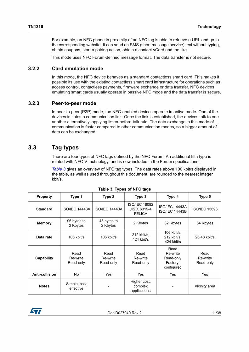
There are four types of NFC tags defined by the NFC Forum. An additional fifth type is related with NFC-V technology, and is now included in the Forum specifications.
Table 3 gives an overview of NFC tag types. The data rates above 100 kbit/s displayed in the table, as well as used throughout this document, are rounded to the nearest integer kbit/s.
Table 3. Types of NFC tags
Property Type 1 Type 2 Type 3 Type 4 Type 5
Standard ISO/IEC 14443A ISO/IEC 14443AISO/IEC 18092JIS X 6319-4
FELICA
ISO/IEC 14443AISO/IEC 14443B
ISO/IEC 15693
Memory96 bytes to2 Kbytes
48 bytes to2 Kbytes
2 Kbytes 32 Kbytes 64 Kbytes
Data rate 106 kbit/s 106 kbit/s212 kbit/s,424 kbit/s
106 kbit/s, 212 kbit/s, 424 kbit/s
26.48 kbit/s
CapabilityRead
Re-writeRead-only
ReadRe-write
Read-only
ReadRe-write
Read-only
ReadRe-write
Read-onlyFactory-
configured
ReadRe-write
Read-only
Anti-collision No Yes Yes Yes Yes
NotesSimple, cost
effective-
Higher cost, complex
applications- Vicinity area

Technology TN1216
12/38 DocID027940 Rev 2
3.3.1 Type-1 tag
Type-1 tag is compliant with ISO/IEC 14443A specification. It is read-write-capable and it may be user-configurable to read-only mode. The memory size ranges from 93 bytes to 2 Kbytes and the communication speed or data rate is of 106 kbit/s.Type-1 tag does not support anti-collision mechanism.
3.3.2 Type-2 tag
Type-2 tag is compliant with ISO/IEC 14443A specification. It is read-write-capable and it may be user-configurable to read-only mode. The memory size ranges from 48 bytes to 2 Kbytes and the communication speed or data rate is of 106 kbit/s.Type-2 tag supports anti-collision mechanism.
3.3.3 Type-3 tag
Type-3 tag is compliant with ISO/IEC 18092 and JIS X 6319-4 standards, except for encryption and authentication that are not supported. Even if featuring read / write capability, a tag of type 3 can be set to read-only mode. Specific service equipment may be used to enable re-writing of type-3 tag data in the field. Type-3 tag contains two Kbytes of memory. The data rate is 212 kbit/s or 424 kbit/s. Type-3 tag supports anti-collision mechanism.
3.3.4 Type-4 tag
Type-4 tag complies with both A and B versions of ISO/IEC 14443 standard. The type-4 tag is factory-set to read-only mode and specific service equipment is require for updating its data. Type-4 tag contains up to 32 Kbytes of memory, supports 106 kbit/s, 212 kbit/s and 424 kbit/s data rates, as well as the anti-collision mechanism.
3.3.5 Type-5 tag
Type-5 tag (NFC-V) has recently been adopted by NFC Forum specification. It relies on ISO/IEC 15693 standard, contains more than 64 Kbytes of memory, supports 26.48 kbit/s data rate and anti-collision mechanism.
3.4 RF field and over-the-air interface
3.4.1 Inductive coupling
NFC uses electromagnetic induction between two loop antennas located within each other's near field, effectively forming an air-core transformer. It operates within the globally available and unlicensed radio frequency band of 13.56 MHz. Most of the RF energy is concentrated in the allowed ±7 kHz bandwidth range, but the full spectral envelope, when using ASK modulation, may be as wide as 1.8 MHz.
The inductive coupling not only allows the coupled proximity (PCD, PICC) or vicinity (VCD, VICC) devices to exchange information, but also to transfer power from the coupling device (PCD, VCD) to the card (PICC, VICC).
As coupling device signals data to card by directly modulating the RF field, the mean energy of the RF field during data transfer decreases. Different methods of modulation and data encoding lead to different levels of RF field mean energy decrease. Techniques selected for
DocID027940 Rev 2 13/38
TN1216 Technology
37
VCD and VICC, described in Section 3.5, aim at minimizing the loss of RF field energy during VCD-to-VICC data transfer. It is of more importance for vicinity equipment than it is for proximity equipment, as vicinity equipment has to operate at larger coupling distances. Larger coupling distance cannot be compensated for with more power of the generated RF field; coupling devices must always respect power limits permitted by international radio-frequency regulations.
3.4.2 Direct and indirect modulation
The coupling device signals data to the listening device by directly modulating the RF field magnitude. The listening device signals data to the coupling device by load-modulating the RF field magnitude, applying variable load to its antenna, that is, to the secondary winding of the transformer. This indirect modulation causes variations detected by the coupling device and interpreted as data.
Modulation index
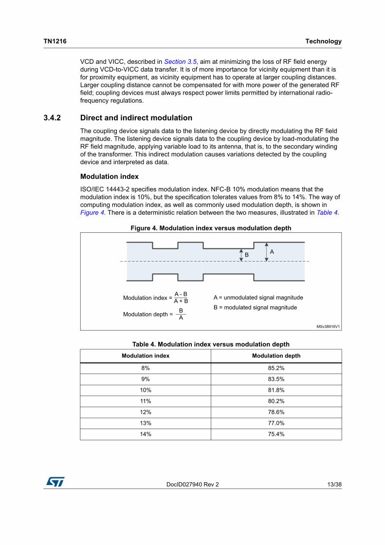
ISO/IEC 14443-2 specifies modulation index. NFC-B 10% modulation means that the modulation index is 10%, but the specification tolerates values from 8% to 14%. The way of computing modulation index, as well as commonly used modulation depth, is shown in Figure 4. There is a deterministic relation between the two measures, illustrated in Table 4.
Figure 4. Modulation index versus modulation depth
Table 4. Modulation index versus modulation depth
Modulation index Modulation depth
8% 85.2%
9% 83.5%
10% 81.8%
11% 80.2%
12% 78.6%
13% 77.0%
14% 75.4%
Technology TN1216
14/38 DocID027940 Rev 2
The modulation index number is about half of what would suggest a corresponding diagram. For example, the difference between A and B values in Figure 4 would suggest about 30%, while the real figure of modulation index for the waveform as displayed is only about 15%. Users designing NFC-B readers for the first time often misinterpret the 10% modulation index requirement and set the modulation depth to 90%, which corresponds to about 5% modulation index and drives their design out of specification.
As stated in section 9.1.2 of ISO/IEC 14443-2, the rise and fall times of the modulation envelope must be two microseconds or less. The amplitude of overshoot and undershoot may not exceed 10% of (A - B). Figure 4 illustrates the definition of A and B.
Load modulation principle
NFC listener signals data by back-scattering the RF field, that is, by causing its intensity to variate. This is achieved by absorbing more or less energy from the field, through the technique called load modulation, that is, modulation of load that the listener imposes to the RF field generated by the reader.
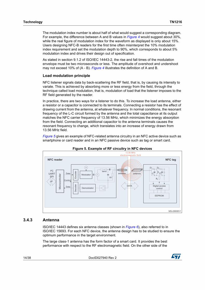
In practice, there are two ways for a listener to do this. To increase the load antenna, either a resistor or a capacitor is connected to its terminals. Connecting a resistor has the effect of drawing current from the antenna, at whatever frequency. In normal conditions, the resonant frequency of the L-C circuit formed by the antenna and the total capacitance at its output matches the NFC carrier frequency of 13.56 MHz, which minimizes the energy absorption from the field. Connecting an additional capacitor to the antenna terminals causes the resonant frequency to change, which translates into an increase of energy drawn from 13.56 MHz field.
Figure 5 gives an example of NFC-related antenna circuitry in an NFC active device such as smartphone or card reader and in an NFC passive device such as tag or smart card.
Figure 5. Example of RF circuitry in NFC devices
3.4.3 Antenna
ISO/IEC 14443 defines six antenna classes (shown in Figure 6), also referred to in ISO/IEC 15693. For each NFC device, the antenna design has to be studied to ensure the optimum performance in the target environment.
The large class-1 antenna has the form factor of a smart card. It provides the best performance with respect to the RF electromagnetic field. On the other side of the
DocID027940 Rev 2 15/38
TN1216 Technology
37
standardized antenna class spectrum, the class-6 antenna is the smallest one and provides the best integration properties, at the expense of performance.

Te
chn
olo
gy
TN
121
6
16/3
8D
ocID027
940 Re
v 2
Figure 6. PICC antenna classes defined in ISO/IEC 14443
DocID027940 Rev 2 17/38
TN1216 Technology
37
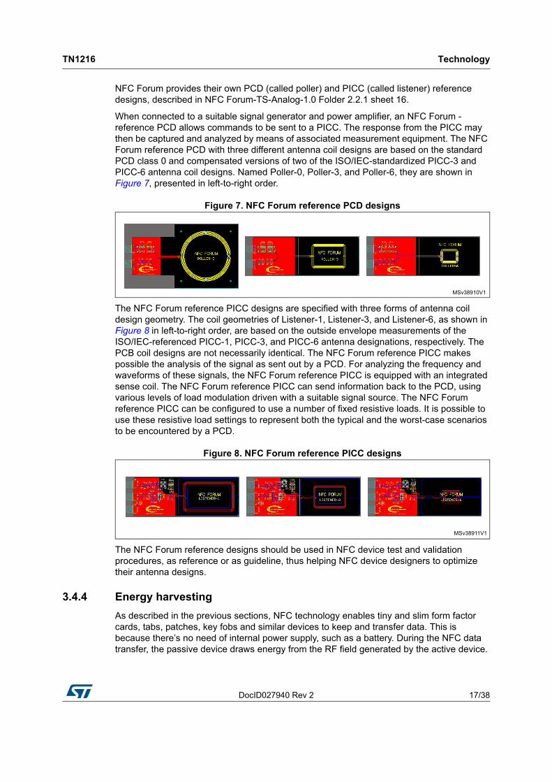
NFC Forum provides their own PCD (called poller) and PICC (called listener) reference designs, described in NFC Forum-TS-Analog-1.0 Folder 2.2.1 sheet 16.
When connected to a suitable signal generator and power amplifier, an NFC Forum - reference PCD allows commands to be sent to a PICC. The response from the PICC may then be captured and analyzed by means of associated measurement equipment. The NFC Forum reference PCD with three different antenna coil designs are based on the standard PCD class 0 and compensated versions of two of the ISO/IEC-standardized PICC-3 and PICC-6 antenna coil designs. Named Poller-0, Poller-3, and Poller-6, they are shown in Figure 7, presented in left-to-right order.
Figure 7. NFC Forum reference PCD designs
The NFC Forum reference PICC designs are specified with three forms of antenna coil design geometry. The coil geometries of Listener-1, Listener-3, and Listener-6, as shown in Figure 8 in left-to-right order, are based on the outside envelope measurements of the ISO/IEC-referenced PICC-1, PICC-3, and PICC-6 antenna designations, respectively. The PCB coil designs are not necessarily identical. The NFC Forum reference PICC makes possible the analysis of the signal as sent out by a PCD. For analyzing the frequency and waveforms of these signals, the NFC Forum reference PICC is equipped with an integrated sense coil. The NFC Forum reference PICC can send information back to the PCD, using various levels of load modulation driven with a suitable signal source. The NFC Forum reference PICC can be configured to use a number of fixed resistive loads. It is possible to use these resistive load settings to represent both the typical and the worst-case scenarios to be encountered by a PCD.
Figure 8. NFC Forum reference PICC designs
The NFC Forum reference designs should be used in NFC device test and validation procedures, as reference or as guideline, thus helping NFC device designers to optimize their antenna designs.
3.4.4 Energy harvesting
As described in the previous sections, NFC technology enables tiny and slim form factor cards, tabs, patches, key fobs and similar devices to keep and transfer data. This is because there’s no need of internal power supply, such as a battery. During the NFC data transfer, the passive device draws energy from the RF field generated by the active device.

Technology TN1216
18/38 DocID027940 Rev 2
Figure 9 illustrates how this happens. Upon application of the RF field to the antenna, the IC transforms the inducted energy into electrical current to supply the tag IC, the microcontroller and, possibly, other components such as a sensor. The components operate as long as the RF field is present and strong enough to supply them. The tag IC can use another GPO to wake up the microcontroller when the RF field is strong enough.
Figure 9. Energy harvesting from RF field
The energy harvesting function brings multiple benefits:
• enabling battery-free NFC products such as tags or smart cards
• waterproofing: no need of connectors or battery compartment
• battery life saving on battery-powered devices
• automatic wakeup when an NFC device comes in proximity
• current supply to other components, in the range of 3 mA
3.5 Data transfer
Data transfer between NFC reader (polling device) and listener (a tag or a smart card) is ensured with data signaling and data coding. The goal of the data signaling is to reliably distinguish binary states. The goal of data coding is to organize binary states in a way to form a binary data stream of logical ones and zeros that can be reliably interpreted by the data receiving side. For data signaling, techniques like direct RF field modulation (reader) and indirect RF field modulation (listener) are used. For binary data stream, bit-coding into ones and zeros is done using know data coding methods. Different types of NFC (NFC-A, NFC-B, NFC-V) may use different techniques or values.
The following sections provide details on different aspects of NFC data transfer (NFC-F variant is not described as it is proprietary).
3.5.1 NFC-A data transfer
NFC-A PCD-to-PICC data transfer
NFC-A PCD-to-PICC data signaling employs 100% amplitude modulation (modulation index of 100%) of the RF field 13.56 MHz carrier. The bits in the binary data stream are encoded with modified-Miller code, as shown in Figure 10.

DocID027940 Rev 2 19/38
TN1216 Technology
37
Figure 10. NFC-A PCD-to-PICC data transfer
With 100% ASK modulation, the RF field completely disappears for short periods of time. During these field holes, the listening device (card) cannot draw energy from the field. In the active periods of the 100% ASK modulation, the NFC circuitry on the card must store enough energy to continue supplying the listener such as tag or card during the field holes.
NFC-A PICC-to-PCD data transfer
NFC-A PICC-to-PCD data signaling goes through varying the load that the listener’s antenna circuit imposes to the RF field, which causes the RF field magnitude variations. The rate of the variation is of 848 kHz, that is, eight-time multiple of the data rate, which creates what is called sub-carrier in the RF field magnitude. The NFC-A listener then keys the sub-carrier with a technique called on-off keying (OOK), altering periods with no sub-carrier with periods of sub-carrier (additional load at the sub-carrier frequency). Specific timing of the OOK then ensures the encoding of logical 0s and 1s in the bit stream; Manchester coding is used. Figure 11 illustrates all aspects of NFC-A PICC-to-PCD data transfer.
Figure 11. NFC-A PICC-to-PCD data transfer
3.5.2 NFC-B data transfer
NFC-B PCD-to-PICC data transfer
NFC-B PCD-to-PICC data signaling is based on 10% ASK modulation. The RF field is continuously present, enabling the use of NRZ (non-return-to-zero) method to encode data, as indicated in Figure 12.

Technology TN1216
20/38 DocID027940 Rev 2
Figure 12. NFC-B PCD-to-PICC data transfer
NFC-B PICC-to-PCD data transfer
NFC-B PICC-to-PCD data signaling employs, like in the case of NFC-A, the same ASK modulation of the load in the rhythm of 848 kHz, forming a sub-carrier. However, instead of on-off keying the sub-carrier, the NFC-B listener uses a technique called BPSK, shifting the sub-carrier phase at given instants by its half-period. The envelope timing of BPSK phase shifts follows NRZ coding and ensures a reliable definition of logical levels in the binary data stream. Figure 13 illustrates all aspects of NFC-B PICC-to-PCD data transfer.
Figure 13. NFC-B PICC-to-PCD data transfer
3.5.3 NFC-V data transfer
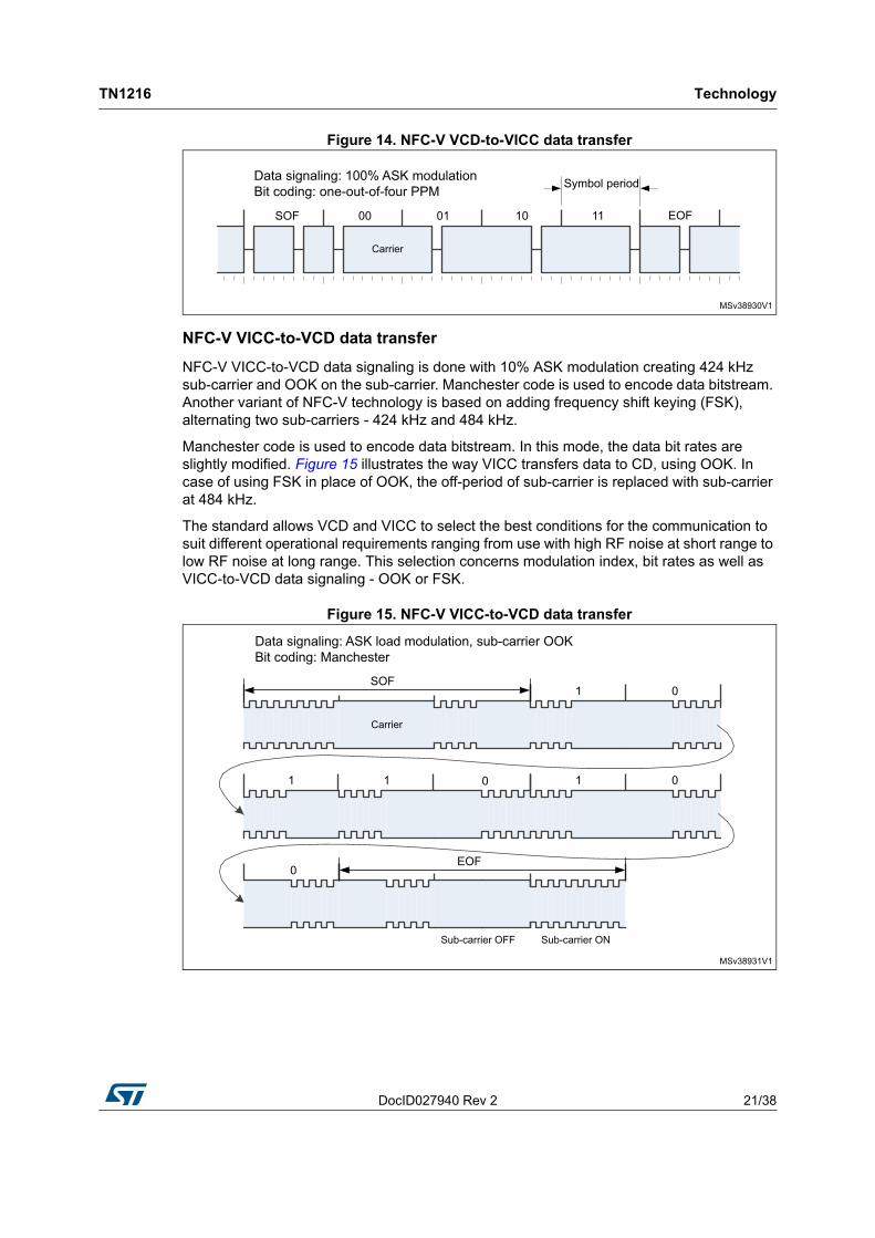
NFC-V VCD-to-VICC data transfer
NFC-V VCD-to-VICC data signaling is based on 10% or 100% ASK modulation. The bit encoding uses one-out-of-four or one-out-of-256 pulse position modulation (PPM) technique. Figure 14 shows the way VCD transfers data to VICC, using one-out-of-four PPM coding. Pulse is in reality a hole taking one eighth of symbol period. One symbol encodes a bit pair. Pulse of each of four bit-pair values takes a time slot reserved to it within the symbol period. Start-of-frame (SOF) and end-of-frame (EOF) symbols use time slots not used by the bit pairs.
The use of PPM for data encoding leads to high RF field duty cycle, in particular in the case of one-out-of-256 system. This makes possible the use of high modulation index, ensuring strong data signaling like in NFC-A, while keeping the RF mean energy decrease low, as in NFC-B.
DocID027940 Rev 2 21/38
TN1216 Technology
37
Figure 14. NFC-V VCD-to-VICC data transfer
NFC-V VICC-to-VCD data transfer
NFC-V VICC-to-VCD data signaling is done with 10% ASK modulation creating 424 kHz sub-carrier and OOK on the sub-carrier. Manchester code is used to encode data bitstream. Another variant of NFC-V technology is based on adding frequency shift keying (FSK), alternating two sub-carriers - 424 kHz and 484 kHz.
Manchester code is used to encode data bitstream. In this mode, the data bit rates are slightly modified. Figure 15 illustrates the way VICC transfers data to CD, using OOK. In case of using FSK in place of OOK, the off-period of sub-carrier is replaced with sub-carrier at 484 kHz.
The standard allows VCD and VICC to select the best conditions for the communication to suit different operational requirements ranging from use with high RF noise at short range to low RF noise at long range. This selection concerns modulation index, bit rates as well as VICC-to-VCD data signaling - OOK or FSK.
Figure 15. NFC-V VICC-to-VCD data transfer
Technology TN1216
22/38 DocID027940 Rev 2
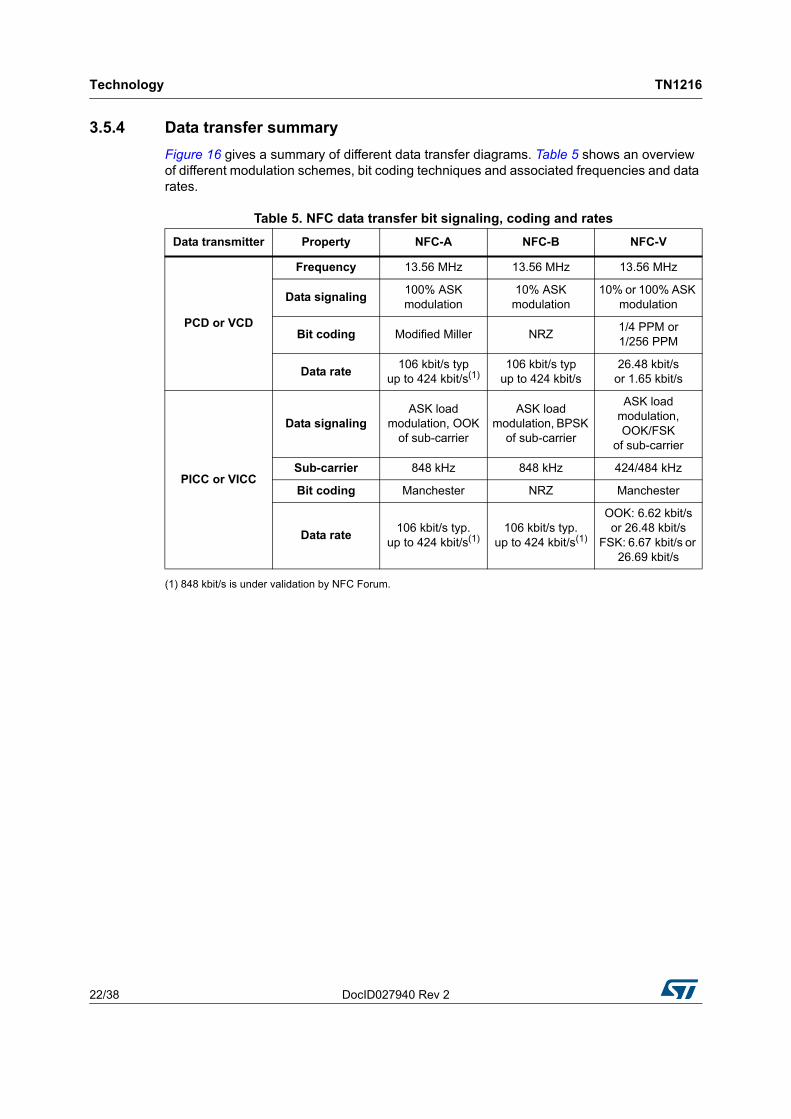
3.5.4 Data transfer summary
Figure 16 gives a summary of different data transfer diagrams. Table 5 shows an overview of different modulation schemes, bit coding techniques and associated frequencies and data rates.
(1) 848 kbit/s is under validation by NFC Forum.
Table 5. NFC data transfer bit signaling, coding and rates
Data transmitter Property NFC-A NFC-B NFC-V
PCD or VCD
Frequency 13.56 MHz 13.56 MHz 13.56 MHz
Data signaling100% ASK modulation
10% ASK modulation
10% or 100% ASK modulation
Bit coding Modified Miller NRZ1/4 PPM or1/256 PPM
Data rate106 kbit/s typ
up to 424 kbit/s(1)106 kbit/s typ
up to 424 kbit/s26.48 kbit/s
or 1.65 kbit/s
PICC or VICC
Data signalingASK load
modulation, OOK of sub-carrier
ASK load modulation, BPSK
of sub-carrier
ASK load modulation, OOK/FSK
of sub-carrier
Sub-carrier 848 kHz 848 kHz 424/484 kHz
Bit coding Manchester NRZ Manchester
Data rate106 kbit/s typ.
up to 424 kbit/s(1)106 kbit/s typ.
up to 424 kbit/s(1)
OOK: 6.62 kbit/s or 26.48 kbit/s
FSK: 6.67 kbit/s or 26.69 kbit/s

TN
12
16T
ech
no
log
y
DocID
027940 R
ev 2
23/38
Figure 16. NFC data transfer summary diagram

Technology TN1216
24/38 DocID027940 Rev 2
3.6 NFC system architecture
As many other systems, NFC technology is built over a structured logical stack of functional layers, transiting from physical to software implementation, as depicted in Figure 17.
The lowest layers are physical - CPU, MCU infrastructure, communication interfaces and radio-related circuitry as defined in ISO/IEC 14443-2 A and B and ISO/IEC 15693-2.
Middle layers include data packeting according to ISO/IEC 14443-3 A and B and ISO/IEC 15693-2 and, generation of commands according to NFC-A, NFC-B, NFC-V and NFC-F. Until this point, there is no NFC-related specificity and the system up to this point corresponds to an RFID system. The first specificity related to NFC comes in form of middle layers dedicated to supporting P2P communication mode. These are the logical link control protocol (LLCP), and simple NDEP exchange protocol (SNEP), as defined in ISO/IEC 18092. As ISO/IEC 18092 also covers one of command protocols, the NFC-F, the LLCP and SNEP in Figure 17 are displayed at the same level.
The next higher layers of the stack, NDEF messages and NDEF records, are also NFC specific. They are usually implemented in SW and accessed to with a user interface, the highest layer of the NFC logical functional stack. Section 3.7 brings additional information on NDEF.
Figure 17. NFC system functional stack
3.7 NDEF structure
NFC data exchange format, NDEF, is one of major items that NFC standards add upon the generic RFID. NDEF is used across all NFC devices, regardless of the underlying tag type or NFC device technology.

DocID027940 Rev 2 25/38
TN1216 Technology
37
NDEF records are standardized, hence NFC devices know how to interpret them. Some of NDEF records are:
• simple text record
• URI
• smart poster
• signature
• vCard (a standard electronic business card format)
• pairing Bluetooth® or Wi-Fi
NDEF is a light-weight binary message format designed to encapsulate application-defined payload bearing one of more NDEF records into a single message. NDEF records can be of the same or of different type and the size of each of them is limited to (232-1) bytes.
NDEF message is a concatenation of NDEF records that can be looked at as a paragraph bearing a discrete chunk of information, and NDEF records as sentences of that paragraph, each conveying a single piece of information. Both the number and the size of the sentences in the paragraph are variable.
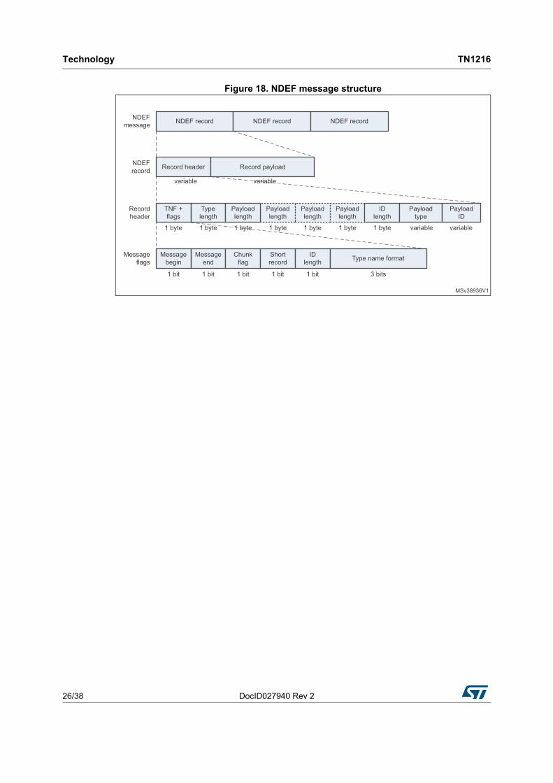
NDEF record is made up of a header and payload. The header describes the payload with three metadata items: payload length, payload type and, optionally, payload identifier.
3.7.1 Payload length
The payload length is a four-byte unsigned integer indicating the number of bytes in the payload. A compact, short-record layout (one byte) is provided for very small payloads. To efficiently detect the NDEF record boundary, the payload length is provided within the first eight bytes of the NDEF record.
3.7.2 Payload type
The NDEF payload type identifier indicates the type of the payload. NDEF supports URIs, MIME media type constructs and an NFC-specific type format as type identifiers. By indicating the type of a payload, it is possible to dispatch the payload to the appropriate user application.
3.7.3 Payload identifier
A payload may be given an optional identifier in the form of an absolute or relative URI. The use of an identifier enables payloads supporting URI linking technologies to cross-reference other payloads.
Technology TN1216
26/38 DocID027940 Rev 2
Figure 18. NDEF message structure

DocID027940 Rev 2 27/38
TN1216 Standards
37
4 Standards
NFC technology is based on a series of standards, such as ISO/IEC 14443, ISO/IEC 15693, ISO/IEC 18092, ECMA-340, ECMA-352 and others.
Compliance with ISO/IEC 14443A (Type A) and ISO/IEC 14443B (Type B) variants is denoted in this document as NFC-A and NFC-B, respectively. Compliance with JIS X 6319 4 and FELICA protocol is denoted as NFC-F. Compliance with ISO/IEC 15693 is denoted as NFC-V, where “V” signifies vicinity - for maximum distance of operation extended to about 1 meter. Peer-to-peer (P2P) communication mode specifically described in ISO/IEC 18092 is denoted as P2P. NFC interface and protocol fit with ISO/IEC 18092, ECMA-340 and ECMA-352 and is referred to as NFCIP.
The scope is to standardize the three NFC communication modes, with their protocols and data exchange formats and bit rates. The currently defined bit rates are 106 kbit/s, 212 kbit/s, 424 kbit/s, 848 kbit/s and, within NFC-V, 1.65 kbit/s, 6.62 kbit/s (ASK with OOK), 6.67 kbit/s (ASK with FSK), 26.48 kbit/s (ASK with OOK) and 26.69 kbit/s (ASK with FSK).
On top of standards by international standardization bodies, NFC Forum provides a number of technical specifications of protocols, data exchange format, NFC Forum tag types, NFC record type and more.
NFC enables smartphones to work at a basic level with legacy RFID readers. In card emulation mode of communication, an NFC device must transmit, at minimum, a unique ID number to a legacy reader. The NFC Forum has defined a common data format called NFC Data Exchange Format (NDEF) that stores and transports various items. The NFC Forum also added the Simple NDEF Exchange Protocol (SNEP) to the specification, to enable sending and receiving messages between two NFC-enabled devices communicating in peer-to-peer mode.
Figure 19 shows a simplified stack of layers forming the NFC technology. The upper layers are specific to NFC while the lower layers also apply to non-NFC technologies such as RFID.
Figure 19. Simplified stack of NFC layers
Figure 20 shows an overview of NFC-related standards and specifications.

Stan
da
rds
TN
121
6
28/3
8D
ocID027
940 Re
v 2
Figure 20. Map of NFC-related standards and specifications

DocID027940 Rev 2 29/38
TN1216 Standards
37
4.1 Legacy ISO/IEC standards
This section lists standards that existed before the introduction of, and adopted by, NFC technology. Their primary use was to standardize RFID technology.
4.1.1 ISO/IEC 14443 - Proximity cards
The standard includes four parts.
ISO/IEC 14443-1:2008 - Physical characteristics
This part of ISO/IEC 14443 standard defines the size and physical characteristics of the card. It also lists several environmental stress conditions that the card must be capable of withstanding without permanent damage to its operation. These tests are intended to be performed at the card level and are dependent on the construction of the card and on the antenna design. Most of the requirements cannot be directly translated to IC or die level.
ISO/IEC 14443-2:2015 - Radio frequency power and signal balance
This part defines the RF power and signal interface for two signaling schemes, Type A and Type B. Both schemes are half-duplex with 106 kbit/s data rate in each direction. Data transmitted by the card is load-modulated with 848 kHz sub-carrier. The card is powered by the RF field. No battery is required.
ISO/IEC 14443-3:2014 - Initialization and anti-collision
This part describes the initialization and anti-collision protocols for Type-A- and Type-B PICC. The anti-collision commands, responses, data frame and timing are defined. The initialization and anti-collision scheme is designed so as to permit the design of multi-protocol readers capable of communicating with both Type-A- and Type-B cards. In RF field, both card types wait silently for a polling command. A multi-protocol reader polls for one type of card, completes any transactions with a card responding and then polls for another type of card.
ISO/IEC 14443-4:2015 - Transmission protocol
This part defines high-level data transmission protocols for Type-A- and Type-B PICC. These protocols are optional so PICCs may be designed with or without supporting them. PICC reports to PCD its capability in the response to the polling command as defined in part 3 of the standard. In this way, the PCD knows whether the PICC supports high-level protocols defined in this part of ISO/IEC 14443 standard.
Protocols defined in part 4 also enable transferring application data units as defined in ISO/IEC 7816-4 and application selection as defined in ISO/IEC 7816-5. ISO/IEC 7816 is Contacted IC card standard.
4.1.2 ISO/IEC 15693 - Vicinity cards
ISO/IEC 15693 standard is member of a series of international standards that describe contactless smart cards in vicinity area. It consists of three parts.
ISO/IEC 15693-1:2010(E)
This part of ISO/IEC 15693 standard specifies physical characteristics of vicinity cards (VICC). It applies to identification cards of type ID-1 (specified in ISO/IEC 7810), operating in vicinity of a coupling device.

Standards TN1216
30/38 DocID027940 Rev 2
ISO/IEC 15693-2:2009
This part specifies the nature and characteristics of field to be provided for bi-directional communication between vicinity coupling device (VCD) and VICC and for powering VICC through harvesting energy from the field.
ISO/IEC 15693-3:2010
This part defines initialization and anti-collision commands interpreted by VICC and VCD.
4.2 Standards specific to NFC
NFC interface and protocol (NFCIP) is defined in ISO/IEC 18092 but also in ECMA-340 and ECMA-352, standards of the European computer manufacturers association (ECMA). They specify modulation schemes, coding, data rates and frame formats of the RF interface, initialization schemes and conditions required for data anti-collision control during initialization, for both passive and active NFC operating modes. They also define the transport protocol, including protocol activation and data-exchange methods.
4.2.1 ISO/IEC 18092 - NFC interface and protocol 1 (NFCIP-1)
This standard defines communication modes for NFC interface and protocol (NFCIP-1), using inductive-coupled devices operating at the center frequency of 13.56 MHz, for interconnection of computer peripherals.
ISO/IEC 18092 also defines the active and passive operating modes of NFCIP-1 to set up a communication network using NFC devices for networked products and for consumer equipment.
In particular, it specifies modulation schemes, coding, transfer speeds and frame format of the RF interface. It also describes initialization schemes and conditions required for data anti-collision control during the initialization, as well as transport protocol including protocol activation and data exchange methods.
ISO/IEC 18092 is aligned with ISO/IEC 13157-1:2010 (NFCIP-1 security services and protocol) and conforms with ISO/IEC 14443-2, ISO/IEC 14443-3 and ISO/IEC 14443-4, as well as with ISO/IEC 15693-1, ISO/IEC 15693-2 and ISO/IEC 15693-3.
4.2.2 ECMA-340: 2013 - NFC interface and protocol 1 (NFCIP-1)
This standard describes NFC interface and protocol 1 (NFCIP-1) and is compliant with ISO/IEC 18092.
4.2.3 ECMA-352: 2013 - NFC interface and protocol 2 (NFCIP-2)
This standard describes NFC interface and protocol 2 (NFCIP-2) and is compliant with ISO/IEC 21481.

DocID027940 Rev 2 31/38
TN1216 NFC interface ICs
37
5 NFC interface ICs
Different categories of NFC-dedicated peripheral ICs serve a wide variety of NFC-enabled electronic devices, ranging from simple tags to complex products such as smartphones. They can be static tag ICs, dynamic tag ICs and NFC readers/controllers.
STMicroelectronics develops and manufactures semiconductor products for each of these categories.
5.1 Tag ICs
This type of IC ensures the operation of a static NFC tag. Static NFC tag is a passive NFC device in the sense that, it cannot generate RF filed. Data stored in a tag can be read or modified by an active NFC device, such as a NFC reader or smartphone. The tag uses load modulation to signal data to reader. The tag can stand alone in a form of a patch, key remote control, or be integrated in a bigger device. It draws power from the RF field so as to operate without its own power supply. The memory is non-volatile, such as EEPROM.
Figure 21. Tag IC
Figure 21 shows an example of tag IC. Among STMicroelectronics products, the ST25Tx series is specifically designed and optimized for use in passive tags.
5.2 Dynamic tag IC
This type of IC allows the operation of a dynamic NFC tag. Dynamic tags are usually integrated into an electronic device.
They have the same properties and behave as static tags when interacting with an NFC device (a reader). On top of entirely supporting static tag functionality, the device where the dynamic tag is integrated into has also the possibility of reading and writing the tag memory contents. To enable this, a dynamic tag IC has interfaces such as serial communication bus, to interact with an MCU on the hosting electronic device.
The read/write by the other NFC device and the read/write by the own device MCU do not necessarily happen at the same moment in time. For example, the dynamic tag contents may be modified while the tag hosting device is powered down and the read / write by the

NFC interface ICs TN1216
32/38 DocID027940 Rev 2
local MCU happen when the tag hosting device is switched on, hours or days later. This resembles to an email communication between the external NFC device and the MCU of the tag-hosting NFC device, where the EEPROM of the tag IC plays the role of a mailbox.
Figure 22 shows an example of dynamic tag IC. Products of the M24LR, M24SR and ST25D Series are designed and optimized for use in dynamic tags. Optionally, a GPO/Interrupt signal is available to wake up the microcontroller, in order to optimize the power consumption.
Figure 22. Dynamic tag IC
5.3 NFC readers and controllers
Two types of products cover NFC access, they are NFC readers and NFC controllers.
5.3.1 NFC readers
A NFC reader is able to setup and sustain communications with a tag or a NFC controller in all NFC modes.
ST products address the main NFC markets:
• Physical access (by supporting all Tags and Cards all NFC types (1 to 5) with all protocols)
• Public transport (handling ISO 14443A&, open systems)
• Automotive, covering, among others, Access control, Engine start, pairing capacities
• Consumer, enabling communication to phones Pairing (Wi-Fi or Bluetooth®) configuration
• Industrial, initiating P2P communication to mobile phone, item tagging and tracking
• Gaming
• Point of sales: bridge to Pure EMV (Europay Mastercard Visa), Payment including P2P couponing
The peer-to-peer (P2P) communication mode is an active NFC mode of operation requiring two active NFC devices. Both devices also support load modulation as it is required for the initial phase of peer-to-peer link setting. The device that first successfully accomplishes the polling process becomes initiator and keeps that role till the end of the P2P transaction. The other device plays the role of target.

DocID027940 Rev 2 33/38
TN1216 NFC interface ICs
37
Once the communication link is established, the peers maximize the use of direct modulation and alternatively generate RF field and transmit data then switch off RF field and receive data from the other peer. This resembles to a live human discussion as it necessarily happens at the same moment in time. Using the direct field modulation results in higher communication speeds and efficiency. An interface IC featuring P2P communication mode needs to support, on top of dynamic tag IC functionality, own RF field generation and provide physical assets, such as RAM buffer.
Devices (like smartphones) that need to support P2P mode make use of this kind of NFC interface IC that meets the requirements for dynamic and static tag interface IC.
Figure 23 shows the typical architectural blocks of an NFC P2P interface IC. Among STMicroelectronics silicon IC products, ST95HF fulfills the requirements for a NFC P2P interface. Optionally, a GPO/Interrupt signal is available to wake up the microcontroller in order to optimize the power consumption of the system.
Figure 23. P2P interface IC
Figure 24. Features of ST25R39xx products

NFC interface ICs TN1216
34/38 DocID027940 Rev 2
The ST25R39xx products are NFC readers, EMVco compatible, with high performance and high output power, with Very High Bit Rate (VHBR) up to 6.8 Mbit/s for faster data transmission. As shown in Figure 24, they feature capacitive/inductive wakeup (resulting in very low sleep current and low power capabilities), Antenna auto tuning (inducing very sensitive and accurate tag detection), and P2P communication in active target mode.
5.3.2 NFC controller
NFC controllers (see Figure 25) support the following requirements:
• Reader mode: T1, T2, T3, ISO14443 A/B, T4, T5 as defined in chapter 7.3.1
• Card Emulation ISO 14443 A/B, Type F The NFC Controller allows to route data to different hosts, like Device Host (Host Card Emulation) or SWP host (SIM card or embedded secure element)
• Peer to Peer in passive or active mode (ISO 18092)
Figure 25. NFC controller
The NFC Forum describes a Discovery mechanism (polling loop) that allows the NFC Controller to periodically switch between the three modes.

DocID027940 Rev 2 35/38
TN1216 NFC interface ICs
37
With reference to Figure 26:
1. First, an RF field is generated,
2. An ATR_REQ command for the active communication mode is sent (P2P)
3. If no answer is received, the SENS_REQ command for the type A protocol is issued (for tag Type 1, 2 and T4A)
4. If no response is received within the maximum response time, the polling loop switches to the next type B protocol by sending a SENSB_REQ command
5. If this command is not answered, a SENSF_REQ is sent (for T3)
6. If no answer is received, an INVENTORY_REQ command is sent (for Vicinity)
7. If no answer is received, the polling loop switches to listen mode to sense for remote RF fields (i.e. Card emulation).
Figure 26. NFC controller mode management
Conclusion TN1216
36/38 DocID027940 Rev 2
6 Conclusion
Thanks to this technical note readers and users have easier access to basic information on NFC technology, a powerful tool thanks to its possibility of being part of Internet of Things, a network of devices and systems adding value through their interconnection.
The document helps readers orient themselves in the landscape of standards that govern NFC technology, making them able to take right decisions, such as purchasing copies of standards they need to understand in detail for their NFC-related projects.
The ST25 NFC / RFID Tags and Readers products described in this document are used in NFC electronic devices, in several applications. For more information, visit dedicated webpages on www.st.com, or contact your local sales office.

DocID027940 Rev 2 37/38
TN1216 Revision history
37
7 Revision history
Table 6. Document revision history
Date Revision Changes
22-Jun-2015 1 Initial release.
14-Oct-2016 2
Updated document title, Introduction, Section 3.1.1: Passive mode, Section 3.1.2: Active mode, Section 3.3: Tag types, Section 3.3.5: Type-5 tag, Section 3.5.2: NFC-B data transfer, Section 5: NFC interface ICs, Section 5.1: Tag ICs, Section 5.2: Dynamic tag IC, Section 5.3: NFC readers and controllers and Section 6: Conclusion.
Added Section 5.3.1: NFC readers and Section 5.3.2: NFC controller.
Updated Table 1: NFC terminology and Table 3: Types of NFC tags.
Added Table 2: Operating conditions of NFC devices in passive mode and updated title of Figure 21: Tag IC.

TN1216
38/38 DocID027940 Rev 2
IMPORTANT NOTICE – PLEASE READ CAREFULLY
STMicroelectronics NV and its subsidiaries (“ST”) reserve the right to make changes, corrections, enhancements, modifications, and improvements to ST products and/or to this document at any time without notice. Purchasers should obtain the latest relevant information on ST products before placing orders. ST products are sold pursuant to ST’s terms and conditions of sale in place at the time of order acknowledgement.
Purchasers are solely responsible for the choice, selection, and use of ST products and ST assumes no liability for application assistance or the design of Purchasers’ products.
No license, express or implied, to any intellectual property right is granted by ST herein.
Resale of ST products with provisions different from the information set forth herein shall void any warranty granted by ST for such product.
ST and the ST logo are trademarks of ST. All other product or service names are the property of their respective owners.
Information in this document supersedes and replaces information previously supplied in any prior versions of this document.
© 2016 STMicroelectronics – All rights reserved