tms320c6000 instruction set simulator technical reference
TRANSCRIPT
TMS320C6000 Instruction Set Simulator
Technical Reference Manual
Literature Number: SPRU600I
April 2007

2 SPRU600I–April 2007Submit Documentation Feedback

Contents
Preface ............................................................................................................................... 7
1 Introduction to the TMS320C6000 Simulator .................................................................. 91.1 Features ............................................................................................................ 10
1.2 Supported Processors and Simulator Configurations ........................................................ 10
1.3 Considerations for Choosing a Simulator ...................................................................... 11
1.4 Supported Hardware Resources ................................................................................ 11
1.4.1 CPU ........................................................................................................ 12
1.4.2 Memory .................................................................................................... 12
1.4.3 Peripherals ................................................................................................ 12
2 Supported Simulation Features .................................................................................. 152.1 External Event and Data Simulation ............................................................................ 16
2.1.1 Pin Connect .............................................................................................. 16
2.1.2 Port Connect .............................................................................................. 20
2.2 Reserved Memory Access Detection ........................................................................... 22
2.2.1 Supported Configurations ............................................................................... 22
2.2.2 Configuration Options.................................................................................... 22
2.2.3 Error Reporting Format .................................................................................. 22
2.2.4 Limitations ................................................................................................. 23
2.3 CPU Resource Conflict Detection............................................................................... 23
2.3.1 Supported Configurations ............................................................................... 23
2.3.2 Types of Conflict Detected .............................................................................. 24
2.3.3 Types of Conflict Not Detected ......................................................................... 24
2.3.4 Configuration Options.................................................................................... 24
2.3.5 Error Reporting Format .................................................................................. 24
2.4 Simulator Analysis................................................................................................. 25
2.5 RTDX ............................................................................................................... 25
2.6 DSP/BIOS .......................................................................................................... 25
2.7 Bootload ............................................................................................................ 25
2.8 Application Memory Usage Detection .......................................................................... 25
2.9 EMIF Clock Configuration ........................................................................................ 25
2.10 Rewind.............................................................................................................. 26
2.11 Watchpoint ......................................................................................................... 26
2.12 Compiled Simulation .............................................................................................. 26
2.13 Interrupt Latency Detection ...................................................................................... 27
3 Detailed Capabilities of Individual Configurations ........................................................ 293.1 C62x/C64x/C67x/C672x/C64x+ CPU Cycle Accurate Simulators .......................................... 30
3.2 C6416/C6713/C6412/DM642 Device Functional Simulators ................................................ 30
3.2.1 Supported Features ...................................................................................... 30
3.2.2 Known Limitations ........................................................................................ 31
3.3 C6201/C6202/C6203/C6204/C6205/C6701 Device Simulators............................................. 32
3.3.1 Supported Features ...................................................................................... 32
3.3.2 Known Limitations ........................................................................................ 32
3.4 C6211/C6711/C6712/C6713 Device Cycle Accurate Simulators ........................................... 32
SPRU600I–April 2007 Contents 3Submit Documentation Feedback

3.4.1 Supported Features ...................................................................................... 33
3.4.2 Known Limitations ........................................................................................ 33
3.5 C6411/C6412/C6414/C6415/C6416/DM642 Device Cycle Accurate Simulators ......................... 33
3.5.1 Supported Features ...................................................................................... 33
3.5.2 Known Limitations ........................................................................................ 33
3.6 DM6443/DM6446/C6455/TCI6482 Device Cycle Accurate Simulators .................................... 34
3.6.1 Supported Features ...................................................................................... 34
3.6.2 Known Limitations ........................................................................................ 34
4 Configuring the Simulator ......................................................................................... 354.1 Setting the Resource Conflict Detection Mode ................................................................ 36
4.2 Setting the Reserved Memory Access Detection Mode...................................................... 36
4.3 Setting the Bootload .............................................................................................. 37
4.3.1 Bootload in C6x0x Device Simulators ................................................................. 37
4.3.2 Bootload in C64x Device Cycle Accurate/Device Functional Simulators ......................... 37
4.3.3 Bootload in C64x+ Device Cycle Accurate Simulators .............................................. 37
4.4 Setting the EMIF and CPU Clocks .............................................................................. 38
4.5 Enabling the Rewind Feature.................................................................................... 38
4.6 Setting Up the McBSP XBAR.................................................................................... 38
4.6.1 How to Write an XBAR File ............................................................................. 39
4.6.2 Format of the Configuration File to be Picked Up.................................................... 40
4.7 Setting Up the McASP XBAR.................................................................................... 40
4.7.1 Format of the Configuration File to be Picked Up.................................................... 41
4.8 Setting the Maximum Memory Usage Limit.................................................................... 41
4.9 File Format for Pin Connect...................................................................................... 41
4.9.1 Setting Up the Input File................................................................................. 41
4.9.2 Absolute Clock Cycle .................................................................................... 42
4.9.3 Relative Clock Cycle ..................................................................................... 42
4.9.4 Repetition of Patterns for a Specified Number of Times ............................................ 42
4.9.5 Repetition to the End of Simulation (EOS)............................................................ 42
4.10 File Format for Port Connect..................................................................................... 43
4.11 Base Configuration File........................................................................................... 43
5 Performance Numbers .............................................................................................. 45
6 Cycle Accuracy ........................................................................................................ 476.1 C6000 Simulators Benchmarking ............................................................................... 48
6.2 Notes on Cycle Accuracy ........................................................................................ 49
4 Contents SPRU600I–April 2007Submit Documentation Feedback

List of Tables
1-1 Processors Supported by the C6000 Simulator ........................................................................ 101-2 TMS320C6000 CPU Cycle Accurate Simulator Configurations...................................................... 121-3 TMS320C6201, C6202, C6203, C6204, C6205, and C6701 Simulators ........................................... 121-4 TMS320C6411, C6412, C6414, C6415, C6416, and DM642 Device Cycle Accurate; C6412, C6416 and
DM642 Functional Simulators ............................................................................................ 121-5 TMS320C6211, C6711, C6712, and C6713 Device Cycle Accurate, and C6713 Device Functional
Simulators ................................................................................................................... 132-1 Available Memory Ranges for Port Connect for TMS320C6000 Devices .......................................... 162-2 Available Pins for Configuration of the TMS320C6713 Device ...................................................... 172-3 Available Pins for Configuration of TMS320C6202, C6203, C6412, C6414, C6415, C6416 and DM642
Devices ...................................................................................................................... 182-4 Available Pins for Configuration of TMS320C64x, C62x, C67x, and C672x CPU Cycle Accurate Simulators 182-5 Available Pins for Configuration of TMS320C6412, C6416, C6713, and DM642 Device Functional
Simulators ................................................................................................................... 192-6 Available Pins for Configuration of DM4663, DM6446, TCI6482, and TMX320C6455 Device Simulators..... 192-7 Available Memory Ranges for Port Connect for TMS320C6000 Devices .......................................... 202-8 Resources That Can Appear in the Resource Conflict Error Message ............................................. 242-9 Compiled Simulator Configuration ....................................................................................... 263-1 Timer Memory Map Details in CPU/MegaModule Simulators ........................................................ 304-1 XBAR File Pin Names ..................................................................................................... 395-1 Performance Numbers of the C6000 Simulator ........................................................................ 456-1 Benchmarking Data for C6000 Simulators.............................................................................. 48
SPRU600I–April 2007 List of Tables 5Submit Documentation Feedback

List of Tables6 SPRU600I–April 2007Submit Documentation Feedback

PrefaceSPRU600I–April 2007
Read This First
About This Manual
This manual provides the following information:
• Names the TMS320C6000™ (C6000™) digital signal processors (DSPs) that are supported byconfigurations of the TMS320C6000 Instruction Set Simulator
• Lists which modules and pins of each device are modeled• Describes capabilities and limitations of the simulator• Explains how to configure the simulator• Provides some bench marking data on cycle accuracy
Notational Conventions
This document uses the following conventions:
• Program examples are shown in a special typeface.• In syntax descriptions, key words or symbols are shown in bold and variables are shown in italics.
Portions of a syntax that are in bold should be entered as shown; portions of a syntax that are in italicsdescribe the type of information that should be entered.
• Square brackets ([and]) identify an optional parameter. If you use an optional parameter, you specifythe information within the brackets. Unless the square brackets are in a bold typeface, do not enter thebrackets themselves.
• Braces ( { and } ) indicate that you must choose one of the parameters within the braces; you do notenter the braces themselves.
• The pipe symbol ( | ) represents a logical OR.
Related Documentation From Texas Instruments
TMS320C62x DSP CPU and Instruction Set Reference Guide (SPRU731) describes the architecture,pipeline, instruction set, and interrupts for the TMS320C62x DSPs.
TMS320C64x/C64x+ DSP CPU and Instruction Set Reference Guide (SPRU732) describes thearchitecture, pipeline, instruction set, and interrupts for the TMS320C64x/64x+ DSPs.
TMS320C67x/C67x+ DSP CPU and Instruction Set Reference Guide (SPRU733) describes thearchitecture, pipeline, instruction set, and interrupts for the TMS320C67x/67x+ DSPs.
TMS320C6000 Peripherals Reference Guide (SPRU190) describes common peripherals available onthe TMS320C6000 DSPs. This book includes information on the internal data and program memories, theexternal memory interface (EMIF), the host port, serial ports, direct memory access (DMA), enhanceddirect memory access (EDMA), expansion bus (XBUS), clocking and phase-locked loop (PLL), and thepower-down modes.
TMS320C6000 Code Composer Studio Online Help is accessible through the Code Composer Studio™Integrated Development Environment (IDE).
Trademarks
TMS320C6000, C6000, Code Composer Studio, TMS320C62x, TMS320C64x, TMS320C672x,TMS320C67x, C62x, C64x, C672x, C67x, RTDX, DSP/BIOS are trademarks of Texas Instruments.
Intel, Pentium are registered trademarks of Intel Corporation or its subsidiaries in the United States andother countries.
SPRU600I–April 2007 Read This First 7Submit Documentation Feedback

www.ti.com
Read This First8 SPRU600I–April 2007Submit Documentation Feedback
Chapter 1SPRU600I–April 2007
Introduction to the TMS320C6000 Simulator
The TMS320C6000™ Instruction Set Simulator, available within the Code ComposerStudio™ Integrated Development Environment (IDE) for TMS320C6000, simulates theTMS320C62x™, TMS320C64x™, TMS320C64x+™, TMS320C672x™, andTMS320C67x™ generations of devices. This chapter lists the TMS320C6000 devicessupported by the simulator and provides information to help in the selection of the bestsimulator configuration.
Topic .................................................................................................. Page
1.1 Features................................................................................... 101.2 Supported Processors and Simulator Configurations.................... 101.3 Considerations for Choosing a Simulator .................................... 111.4 Supported Hardware Resources ................................................. 11
SPRU600I–April 2007 Introduction to the TMS320C6000 Simulator 9Submit Documentation Feedback

www.ti.com
1.1 Features
1.2 Supported Processors and Simulator Configurations
Features
The C6000™ simulators support the following features:
• TMS320C6000 CPU full instruction set architecture execution• Support for C62x™, C64x™, C64x+™, C672x™, and C67x™. Support for all devices is based on
these cores.• Port Connect, which also supports external peripheral simulation• Pin Connect, which also supports external interrupt simulation• Analysis events support for debug and analysis• RTDX™ support• DSP/BIOS™ real-time analysis support• CPU resource conflict detection• Rewind support• Watchpoint support• Interrupt latency detection• Compiled simulation
Table 1-1 lists the devices supported by the C6000 Instruction Set Simulator with the correspondingconfiguration to be selected under the Factory Board menu of Code Composer Studio Setup.
Table 1-1. Processors Supported by the C6000 Simulator
Processor Code Composer Studio IDE Import Configuration (1) CPU Modeled
TMS320C62x C62xx CPU Cycle Accurate Simulator TMS320C62x
TMS320C64x C64xx CPU Cycle Accurate Simulator TMS320C64x
TMS320C67x C67xx CPU Cycle Accurate Simulator TMS320C67x
TMS320C6211 C6211 Device Cycle Accurate Simulator TMS320C62x
TMS320C6411 C6411 Device Cycle Accurate Simulator TMS320C64x
TMS320C6412 (2) C6412 Device Cycle Accurate Simulator TMS320C64x
TMS320C6414 C6414 Device Cycle Accurate Simulator TMS320C64x
TMS320C6415 C6415 Device Cycle Accurate Simulator TMS320C64x
TMS320C6416 (2) C6416 Device Cycle Accurate Simulator TMS320C64x
TMS320C6711 C6711 Device Cycle Accurate Simulator TMS320C67x
TMS320C6712 C6712 Device Cycle Accurate Simulator TMS320C67x
TMS320C6713 (2) C6713 Device Cycle Accurate Simulator TMS320C67x
TMS320DM642 (2) DM642 Device Cycle Accurate Simulator TMS320C64x
TMS320C6201 C6201 Device Simulator (3) TMS320C62x
TMS320C6202 C6202 Device Simulator (3) TMS320C62x
TMS320C6203 C6203 Device Simulator (3) TMS320C62x(1) Big Endian and Little Endian (default) configurations are available in the product.(2) Device Functional Simulators are also available for these Device Cycle Accurate Simulators and can be used by changing the
Simulator Type entry in the Code Composer Studio Setup processor properties window from Cycle Accurate to Functional.(3) Map 0 and Map 1 (default) configurations are available.
10 Introduction to the TMS320C6000 Simulator SPRU600I–April 2007Submit Documentation Feedback

www.ti.com
1.3 Considerations for Choosing a Simulator
1.4 Supported Hardware Resources
Considerations for Choosing a Simulator
Table 1-1. Processors Supported by the C6000 Simulator (continued)
Processor Code Composer Studio IDE Import Configuration (1) CPU Modeled
TMS320C6204 C6204 Device Simulator (3) TMS320C62x
TMS320C6205 C6205 Device Simulator (3) TMS320C62x
TMS320C6701 C6701 Device Simulator (3) TMS320C67x
C6455 C6455 Device Cycle Accurate Simulator TMS230C64x+
TCI6482 TCI6482 Device Cycle Accurate Simulator TMS230C64x+
DM6446 DM6446 Device Cycle Accurate Simulator (4) TMS230C64x+
DM6443 DM6443 Device Cycle Accurate Simulator (4) TMS230C64x+
TMS230C64x+ TMS230C64x+ Cycle Accurate Simulator TMS230C64x+
TMS230C64x+ C64x+ CPU Cycle Accurate Simulator TMS230C64x+
TMS320C672x C672x CPU Cycle Accurate Simulator TMS230C672x
Note: Multiple C6000 simulator configurations cannot be imported in Code ComposerStudio Setup.
(4) Only Little Endian configurations are available in the product for this device. Models the DSP subsystems, EDMA v3, and DDR2EMIF only. Does not model the ARM subsystem.
The different simulators provide a tradeoff between the functionality modeled, cycle accuracy of thesimulation, and simulation performance. Different configurations can be selected based on the needs ofthe application, in terms of the target functionality needed and the levels of cycle accuracy required. Youcan choose CPU Cycle Accurate Simulators or Device Cycle Accurate Simulators from the Factory Boardsmenu in Code Composer Studio Setup. For C6x1x simulators, you can create simulator configurations forDevice Functional Simulators by changing the Simulator Type entry in the Code Composer Studio Setupprocessor properties window from Cycle Accurate to Functional.
The CPU cycle-accurate simulator configurations can be selected if your primary interest is in optimizingcore algorithms. Here, you are concerned with the accuracy of the core and do not need full devicesimulation. Any accesses outside the core will be handled by a flat memory; the cycles measured will notaccount for any memory access latencies.
The device functional simulator configurations model the functionality of some of the key peripherals, withminimal impact on simulator performance. The peripherals in these simulators are modeled functionally tosupport the programmer view; they are not cycle-accurate. These configurations can be used when youare interested in the features of the device that are supported in the functional simulator but not present inthe core simulator, and when cycle accuracy is not important.
For example, the C6713 Device Functional Simulator can be used for application development wherecycle accuracy is not needed. The C6713 Device Functional Simulator runs faster than the C6713 DeviceCycle Accurate Simulator.
The device cycle-accurate simulator configurations model most of the peripherals of the devices. Theperipherals are cycle accurate, as in the silicon. These simulators can be used to get an indication of thecycle behavior of an application. For more details on the accuracy of a specific simulator configuration,see Chapter 3.
The following sections provide a concise overview of the supported hardware resources for each of thesimulator configurations. For more detailed information on simulator configurations, see Chapter 3.
SPRU600I–April 2007 Introduction to the TMS320C6000 Simulator 11Submit Documentation Feedback

www.ti.com
1.4.1 CPU
1.4.2 Memory
1.4.3 Peripherals
Supported Hardware Resources
The CPU model is cycle accurate. Cycle effects are modeled.
For each of the device simulators and device cycle-accurate simulators, the cache and internal memorymodels match the cache and memory architecture specifications described in the TMS320C6000Peripherals Reference Guide (SPRU190). They support standard cache behavior such as: LRU linereplacement, direct mapping, set associativity, cache protocols for hit/miss service, snoops, and victims.The allocation policies (allocate on read miss, write-back on write miss, etc.) are also modeled to matchthe device specifications. A flat memory model is hooked up to the EMIF in order to allow for externalmemory accesses.
For the CPU cycle-accurate simulators and device functional simulators, the whole memory range ismodeled as a flat memory.
Note: Setting up memory maps using either the GUI or GEL scripts is not supported.
The following tables show the peripherals supported under each simulator configuration. For moreinformation on these peripherals, see the TMS320C6000 Peripherals Reference Guide (SPRU190).
Table 1-2. TMS320C6000 CPU Cycle Accurate Simulator Configurations
C62x C64x C64x+ C672x C67x
CPU Yes Yes Yes Yes Yes
Flat Memory Yes Yes Yes Yes Yes
Timer Yes Yes Yes Yes Yes
Table 1-3. TMS320C6201, C6202, C6203, C6204, C6205, and C6701 Simulators
C6201 C6202 C6203 C6204 C6205 C6701
CPU Yes Yes Yes Yes Yes Yes
Internal Memory/Cache Yes Yes Yes Yes Yes YesModel
DMA Yes Yes Yes (1) Yes (1) Yes (1) Yes
EMIF Yes Yes Yes Yes Yes Yes
Interrupt Selector Yes Yes Yes Yes Yes Yes
McBSP Yes Yes Yes Yes Yes Yes
Timer Yes Yes Yes Yes Yes Yes
GPIO No No No No No No
HPI/XBUS/PCI No No No No No No
(1) The DMA functionality modeled on this device is the same as that of the C6202 simulator. The enhancements have not beenmodeled.
Table 1-4. TMS320C6411, C6412, C6414, C6415, C6416, and DM642 Device Cycle Accurate; C6412,C6416 and DM642 Functional Simulators
C6411 C6412 C6414 C6415 C6416 DM642 C6412 C6416 DM642FUNC FUNC FUNC
CPU Yes Yes Yes Yes Yes Yes Yes Yes Yes
Internal Memory/ Yes Yes Yes Yes Yes Yes Yes Yes YesCache Model
12 Introduction to the TMS320C6000 Simulator SPRU600I–April 2007Submit Documentation Feedback

www.ti.com
Supported Hardware Resources
Table 1-4. TMS320C6411, C6412, C6414, C6415, C6416, and DM642 Device Cycle Accurate; C6412,C6416 and DM642 Functional Simulators (continued)
C6411 C6412 C6414 C6415 C6416 DM642 C6412 C6416 DM642FUNC FUNC FUNC
QDMA Yes Yes Yes Yes Yes Yes Yes Yes Yes
EDMA Yes Yes Yes Yes Yes Yes Yes Yes Yes
EMIF Yes Yes Yes Yes Yes Yes Yes Yes Yes
Interrupt Selector Yes Yes Yes Yes Yes Yes Yes Yes Yes
McBSP Yes Yes Yes Yes Yes Yes Yes Yes Yes
Timer Yes Yes Yes Yes Yes Yes Yes Yes Yes
GPIO No No No No No No No No No
HPI No No No No No No No No No
TCP/VCP N/A (1) N/A (1) N/A (1) N/A (1) Yes N/A (1) N/A (1) No N/A (1)
Utopia N/A (1) N/A (1) N/A (1) No No N/A (1) N/A (1) No N/A (1)
PCI No No No No No No No No No
McASP N/A (1) N/A (1) N/A (1) N/A (1) N/A (1) Yes N/A (1) N/A (1) No
Videoport N/A (1) N/A (1) N/A (1) N/A (1) N/A (1) No N/A (1) N/A (1) No(1) N/A - Does not exist in the hardware.
Table 1-5. TMS320C6211, C6711, C6712, and C6713 Device Cycle Accurate,and C6713 Device Functional Simulators
C6211 C6711 C6712 C6713 C6713 FUNC
CPU Yes Yes Yes Yes Yes
Internal Memory/Cache Yes Yes Yes Yes YesModel
QDMA Yes Yes Yes Yes Yes
EDMA Yes Yes Yes Yes Yes
EMIF Yes Yes Yes Yes Yes
Interrupt Selector Yes Yes Yes Yes Yes
McBSP Yes Yes Yes Yes Yes
McASP No No No Yes No
Timer Yes Yes Yes Yes Yes
GPIO No No No No No
HPI No No No No No
SPRU600I–April 2007 Introduction to the TMS320C6000 Simulator 13Submit Documentation Feedback

www.ti.com
Introduction to the TMS320C6000 Simulator14 SPRU600I–April 2007Submit Documentation Feedback

Chapter 2SPRU600I–April 2007
Supported Simulation Features
This chapter provides a concise overview of the supported simulation features for eachof the simulator configurations. For more detailed information on each configuration,see Chapter 3.
Topic .................................................................................................. Page
2.1 External Event and Data Simulation ............................................ 162.2 Reserved Memory Access Detection ........................................... 222.3 CPU Resource Conflict Detection................................................ 232.4 Simulator Analysis .................................................................... 252.5 RTDX ....................................................................................... 252.6 DSP/BIOS................................................................................. 252.7 Bootload .................................................................................. 252.8 Application Memory Usage Detection .......................................... 252.9 EMIF Clock Configuration .......................................................... 252.10 Rewind .................................................................................... 262.11 Watchpoint............................................................................... 262.12 Compiled Simulation ................................................................. 262.13 Interrupt Latency Detection ........................................................ 27
SPRU600I–April 2007 Supported Simulation Features 15Submit Documentation Feedback

www.ti.com
2.1 External Event and Data Simulation
2.1.1 Pin Connect
External Event and Data Simulation
In real hardware, the DSP interacts with many external entities. The simulator provides features tosimulate these interactions. The interactions between the simulator and these external entities fall into thefollowing two categories:
• Control Signals trigger activities to the simulator (such as interrupts, serial port clocks, and serial portsynchronization events).
• Data Values are part of an interaction between the simulator and an external entity (such as read andwrite to peripheral registers as a part of I/O memory, and serial port data).
For example, the serial port of the DSP in an audio device is connected to A/D and D/A converters or to acodec. The interaction between the DSP and the audio device happens through transfer of asynchronization signal to start a sample, as well as the sample data itself. Here, the synchronization signalfalls into the Control Signals category and the sample data falls into the Data Values category.
The simulator provides the Pin Connect and Port Connect features for the simulation of these two types ofinteractions, respectively.
The Pin Connect tool allows you to simulate and monitor signals from external interrupts. For taking inexternal interrupts/triggers, some pins are simulated in the TMS320C6000 devices. Any file with thespecified format can be connected to those pins.
The pins being simulated are of two types: pulse and waveform. Pulse pins are sensitive to rising edgesand Waveform pins are sensitive to both rising and falling edges. For example, CPU interrupt pins aresensitive to rising edges, while the clock input pins of the serial port (CLKX, CLKR) of the TMS320C6000devices are sensitive to rising and falling edges. See the following tables for details on the various pinssupported for the different simulator configurations.
Table 2-1. Available Memory Ranges for Port Connect for TMS320C6000Devices
Pin Description Type
NMI Non-maskable interrupt Pulse
INT4 General purpose external interrupt pin Pulse
INT5 General purpose external interrupt pin Pulse
INT6 General purpose external interrupt pin Pulse
INT7 General purpose external interrupt pin Pulse
TINP0 Timer0 input pin Waveform
TINP1 Timer1 input pin Waveform
FSX0 Transmit frame synchronization pin for McBSP0 Waveform
FSR0 Receive frame synchronization pin for McBSP0 Waveform
CLKX0 Transmit clock pin for McBSP0 Waveform
CLKR0 Receive clock pin for McBSP0 Waveform
CLKS0 External clock input for McBSP0 Waveform
FSX1 Transmit frame synchronization pin for McBSP1 Waveform
FSR1 Receive frame synchronization pin for McBSP1 Waveform
CLKX1 Transmit clock pin for McBSP1 Waveform
CLKR1 Receive clock pin for McBSP1 Waveform
CLKS1 External clock input for McBSP1 Waveform
Supported Simulation Features16 SPRU600I–April 2007Submit Documentation Feedback

www.ti.com
External Event and Data Simulation
Table 2-2. Available Pins for Configuration of the TMS320C6713 Device
Pin Description Type
NMI Non-maskable interrupt Pulse
INT4 General purpose external interrupt pin Pulse
INT5 General purpose external interrupt pin Pulse
INT6 General purpose external interrupt pin Pulse
INT7 General purpose external interrupt pin Pulse
TINP0 Timer0 input pin Waveform
TINP1 Timer1 input pin Waveform
FSX0 Transmit frame synchronization pin for McBSP0 Waveform
FSR0 Receive frame synchronization pin for McBSP0 Waveform
CLKX0 Transmit clock pin for McBSP0 Waveform
CLKR0 Receive clock pin for McBSP0 Waveform
CLKS0 External clock input for McBSP0 Waveform
FSX1 Transmit frame synchronization pin for McBSP1 Waveform
FSR1 Receive frame synchronization pin for McBSP1 Waveform
CLKX1 Transmit clock pin for McBSP1 Waveform
CLKR1 Receive clock pin for McBSP1 Waveform
CLKS1 External clock input for McBSP1 Waveform
ACLKX0 Clock pin for transmit section of McASP0 Pulse
ACLKR0 Clock pin for receive section of McASP0 Pulse
AHCLKX0 Clock pin at higher frequencies for transmit section of PulseMcASP0
AHCLKR0 Clock pin at higher frequencies for receive section of PulseMcASP0
AFSX0 Frame sync pin for transmit section of McASP0 Pulse
AFSR0 Frame sync pin for receive section of McASP0 Pulse
ACLKX1 Clock pin for transmit section of McASP1 Pulse
ACLKR1 Clock pin for receive section of McASP1 Pulse
AHCLKX1 Clock pin at higher frequencies for transmit section of PulseMcASP1
AHCLKR1 Clock pin at higher frequencies for receive section of PulseMcASP1
AFSX1 Frame sync pin for transmit section of McASP1 Pulse
AFSR1 Frame sync pin for receive section of McASP1 Pulse
SPRU600I–April 2007 Supported Simulation Features 17Submit Documentation Feedback

www.ti.com
External Event and Data Simulation
Table 2-3. Available Pins for Configuration of TMS320C6202, C6203, C6412,C6414, C6415, C6416 and DM642 Devices
Pin Description Type
NMI Non-maskable interrupt Pulse
INT4 General purpose external interrupt pin Pulse
INT5 General purpose external interrupt pin Pulse
INT6 General purpose external interrupt pin Pulse
INT7 General purpose external interrupt pin Pulse
TINP0 (1) Timer0 input pin Waveform
TINP1 (1) Timer1 input pin Waveform
FSX0 Transmit frame synchronization pin for McBSP0 Waveform
FSR0 Receive frame synchronization pin for McBSP0 Waveform
CLKX0 Transmit clock pin for McBSP0 Waveform
CLKR0 Receive clock pin for McBSP0 Waveform
CLKS0 External clock input for McBSP0 Waveform
FSX1 Transmit frame synchronization pin for McBSP1 Waveform
FSR1 Receive frame synchronization pin for McBSP1 Waveform
CLKX1 Transmit clock pin for McBSP1 Waveform
CLKR1 Receive clock pin for McBSP1 Waveform
CLKS1 External clock input for McBSP1 Waveform
FSX2 (2) Transmit frame synchronization pin for McBSP2 Waveform
FSR2 (2) Receive frame synchronization pin for McBSP2 Waveform
CLKX2 (2) Transmit clock pin for McBSP2 Waveform
CLKR2 (2) Receive clock pin for McBSP2 Waveform
CLKS2 (2) External clock input for McBSP2 Waveform
ACLKR0 (3) Clock pin for receive section of McASP0 Pulse
ACLKX0 (3) Clock pin for transmit section of McASP0 Pulse
AHCLKR0 (3) Clock pin at higher frequencies for receive section of PulseMcASP0
AHCLKX0 (3) Clock pin at higher frequencies for transmit section of PulseMcASP0
AFSR0 (3) Frame sync pin for receive section of McASP0 Pulse
AFSX0 (3) Frame sync pin for transmit section of McASP0 Pulse(1) This pin is applicable only to the C6202 and C6203 Device Simulators.(2) This pin is not applicable to the DM642 Device Cycle Accurate Simulator, as it has only two
McBSPs.(3) This pin is applicable only to the DM642 Device Cycle Accurate Simulator.
Table 2-4. Available Pins for Configuration of TMS320C64x, C62x, C67x, andC672x
CPU Cycle Accurate Simulators
Pin Description Type
NMI Non-maskable interrupt Pulse
INT4 General purpose external interrupt pin Pulse
INT5 General purpose external interrupt pin Pulse
INT6 General purpose external interrupt pin Pulse
INT7 General purpose external interrupt pin Pulse
INT8 (1) General purpose external interrupt pin Pulse
INT9 (1) General purpose external interrupt pin Pulse
INT10 (1) General purpose external interrupt pin Pulse
(1) This pin is applicable only to the C64x+ CPU simulator.
18 Supported Simulation Features SPRU600I–April 2007Submit Documentation Feedback

www.ti.com
External Event and Data Simulation
Table 2-4. Available Pins for Configuration of TMS320C64x, C62x, C67x, andC672x
CPU Cycle Accurate Simulators (continued)
Pin Description Type
INT11 (1) General purpose external interrupt pin Pulse
INT12 (1) General purpose external interrupt pin Pulse
INT13 (1) General purpose external interrupt pin Pulse
INT14 (1) General purpose external interrupt pin Pulse
INT15 (1) General purpose external interrupt pin Pulse
Table 2-5. Available Pins for Configuration of TMS320C6412, C6416, C6713,and DM642 Device Functional Simulators
Pin Description Type
NMI Non-maskable interrupt Pulse
FSX0 Transmit frame synchronization pin for McBSP0 Pulse
FSR0 Receive frame synchronization pin for McBSP0 Pulse
CLKX0 Transmit clock pin for McBSP0 Pulse
CLKR0 Receive clock pin for McBSP0 Pulse
CLKS0 External clock input for McBSP0 Pulse
FSX1 Transmit frame synchronization pin for McBSP1 Pulse
FSR1 Receive frame synchronization pin for McBSP1 Pulse
CLKX1 Transmit clock pin for McBSP1 Pulse
CLKR1 Receive clock pin for McBSP1 Pulse
CLKS1 External clock input for McBSP1 Pulse
FSX2 (1) Transmit frame synchronization pin for McBSP2 Pulse
FSR2 (1) Receive frame synchronization pin for McBSP2 Pulse
CLKX2 (1) Transmit clock pin for McBSP2 Pulse
CLKR2 (1) Receive clock pin for McBSP2 Pulse
CLKS2 (1) External clock input for McBSP2 Pulse(1) This pin is available only on the C6416 Device Functional Simulator.
Table 2-6. Available Pins for Configuration of DM4663, DM6446, TCI6482, and TMX320C6455 DeviceSimulators
Pin Description Type
NMI Non-maskable interrupt Pulse
INT4 General purpose external interrupt pin Pulse
INT5 General purpose external interrupt pin Pulse
INT6 General purpose external interrupt pin Pulse
INT7 General purpose external interrupt pin Pulse
FSX0 Transmit frame synchronization pin for McBSP0 Pulse
FSR0 Receive frame synchronization pin for McBSP0 Pulse
CLKX0 Transmit clock pin for McBSP0 Pulse
CLKR0 Receive clock pin for McBSP0 Pulse
CLKS0 External clock pin for McBSP0 Pulse
FSX1 (1) Transmit frame synchronization pin for McBSP1 Pulse
FSR1 (1) Receive frame synchronization pin for McBSP1 Pulse
CLKX1 (1) Transmit clock pin for McBSP1 Pulse
CLKR1 (1) Receive clock pin for McBSP1 Pulse
(1) This pin is applicable only to the TCI6482 and C6455 simulators.
SPRU600I–April 2007 Supported Simulation Features 19Submit Documentation Feedback

www.ti.com
2.1.2 Port Connect
External Event and Data Simulation
Table 2-6. Available Pins for Configuration of DM4663, DM6446, TCI6482, and TMX320C6455 DeviceSimulators (continued)
Pin Description Type
CLKS1 (1) External clock pin for McBSP1 Pulse
The Pin Connect feature can be enabled through the Code Composer Studio command window, GELcommands, or through the Pin Connect plug-in. See Section 4.9 for more information on the Pin Connectfile format. See Code Composer Studio online help for more information on how to connect anddisconnect a specific pin.
The Port Connect feature allows you to feed in external data to the simulator and send simulator data outto an external entity. External data is fed into and out of the simulator (memory or serial port) through PortConnect files (the file format is discussed in Section 4.10). This feature can be used to setup an input oroutput data stream to the simulator at the supported address. Whenever a file is connected to a memory(port) address for reads, data from the file is accessed whenever there is a read to the memory in thedevice. Similarly, whenever a file is connected to a memory (port) address for writes, all data writes to thataddress will be written to the file. The simulator provides Port Connect for all processor configurations.
In the case of serial ports, data can be transmitted by connecting some files at the memory-mappedlocations for the serial port transmit register in write mode. Similarly, data can be received by connectingsome files at the memory-mapped locations for the serial port receive register in read mode. Availablememory ranges on the TMS320C6000 devices, to which a file can be connected for reading/writing, aregiven in Table 2-7.
Table 2-7. Available Memory Ranges for Port Connect for TMS320C6000 Devices
Configuration File (1) Available Memory Range
C6201 Device Simulator, Map 1 0x0040 0000 - 0x017F FFFFDXR0, DRR0, DXR1, DRR1 (2)
C6201 Device Simulator, Map 0 0x0000 0000 - 0x013F FFFFDXR0, DRR0, DXR1, DRR1 (2)
C6202 Device Simulator, Map 1 0x0040 0000 - 0x017F FFFFDXR0, DRR0, DXR1, DRR1, DXR2, DRR2 (2)
C6202 Device Simulator, Map 0 0x0000 0000 - 0x013F FFFFDXR0, DRR0, DXR1, DRR1, DXR2, DRR2 (2)
C6203 Device Simulator, Map 1 0x0040 0000 - 0x017F FFFFDXR0, DRR0, DXR1, DRR1, DXR2, DRR2 (2)
C6203 Device Simulator, Map 0 0x0000 0000 - 0x013F FFFFDXR0, DRR0, DXR1, DRR1, DXR2, DRR2 (2)
C6204 Device Simulator, Map 1 0x0040 0000 - 0x017F FFFFDXR0, DRR0, DXR1, DRR1 (2)
C6204 Device Simulator, Map 0 0x0000 0000 - 0x013F FFFFDXR0, DRR0, DXR1, DRR1 (2)
C6205 Device Simulator, Map 1 0x0040 0000 - 0x017F FFFFDXR0, DRR0, DXR1, DRR1 (2)
C6205 Device Simulator, Map 0 0x0000 0000 - 0x013F FFFFDXR0, DRR0, DXR1, DRR1 (2)
C6411 Device Cycle Accurate Simulator 0x8000 0000 - 0xBFFF FFFFDXR0, DRR0, DXR1, DRR1 (2)
C6412 Device Cycle Accurate Simulator 0x0800 0000 - 0xBFFF FFFFDXR0, DRR0, DXR1, DRR1 (2)
C6412 Device Functional Simulator 0x8000 0000 - 0xBFFF FFFF
(1) For each configuration listed, Little Endian (default) and Big Endian versions are provided with the same available memoryrange for the serial port connection.
(2) To connect to these peripheral registers, use the memory-mapped addresses. Port connects to the McBSP can be done only tothe following locations: 0x3000 0000 for DX0 and DR0, 0x3400 0000 for DX1 and DR1, and 0x3800 0000 for DX2 and DR2.
20 Supported Simulation Features SPRU600I–April 2007Submit Documentation Feedback
www.ti.com
2.1.2.1 Read Modes
External Event and Data Simulation
Table 2-7. Available Memory Ranges for Port Connect for TMS320C6000 Devices (continued)
Configuration File (1) Available Memory Range
C6414 Device Cycle Accurate Simulator 0x6000 0000 - 0x6FFF FFFF0x8000 0000 - 0xBFFF FFFFDXR0, DRR0, DXR1, DRR1, DXR2, DRR2 (2)
C6415 Device Cycle Accurate Simulator 0x6000 0000 - 0x6FFF FFFF0x8000 0000 - 0xBFFF FFFFDXR0, DRR0, DXR1, DRR1, DXR2, DRR2 (2)
C6416 Device Cycle Accurate Simulator 0x6000 0000 - 0x6FFF FFFF0x8000 0000 - 0xBFFF FFFFDXR0, DRR0, DXR1, DRR1, DXR2, DRR2 (2)
C6416 Device Functional Simulator 0x6000 0000 - 0x6FFF FFFF0x8000 0000 - 0xBFFF FFFFDXR0, DRR0, DXR1, DRR1, DXR2, DRR2 (2)
C6701 Device Simulator, Map 1 0x0040 0000 - 0x017F FFFFDXR0, DRR0, DXR1, DRR1 (2)
C6701 Device Simulator, Map 0 0x0000 0000 - 0x013F FFFFDXR0, DRR0, DXR1, DRR1 (2)
C6211 Device Cycle Accurate Simulator 0x8000 0000 - 0xBFFF FFFFDXR0, DRR0, DXR1, DRR1 (2)
C6711 Device Cycle Accurate Simulator 0x8000 0000 - 0xBFFF FFFFDXR0, DRR0, DXR1, DRR1 (2)
C6713 Device Cycle Accurate Simulator 0x8000 0000 - 0xBFFF FFFFDXR0, DRR0, DXR1, DRR1, McASP0 TXBUF0-15, McASP0RXBUF0-15, McASP1 TXBUF0-15, McASP1 RXBUF0-15 (2)
C6713 Device Functional Simulator 0x8000 0000 - 0xBFFF FFFFDXR0, DRR0, DXR1, DRR1 (2)
DM642 Device Cycle Accurate Simulator 0x8000 0000 - 0xBFFF FFFFDXR0, DRR0, DXR1, DRR1, McASP0 TXBUF0-15, McASP0RXBUF0-15 (2)
DM642 Device Functional Simulator 0x8000 0000 - 0xBFFF FFFFDXR0, DRR0, DXR1, DRR1 (2)
C62xx CPU Cycle Accurate Simulator 0x0000 0000 - 0xFFFF FFFF
C64xx CPU Cycle Accurate Simulator 0x0000 0000 - 0xFFFF FFFF
C67xx CPU Cycle Accurate Simulator 0x0000 0000 - 0xFFFF FFFF
C6455 Device Cycle Accurate Simulator DXR0, DRR0, DXR1, DRR1
TIC6482 Device Cycle Accurate Simulator DXR0, DRR0, DXR1, DRR1
DM6446 Device Cycle Accurate Simulator DXR0, DRR0
DM6443 Device Cycle Accurate Simulator DXR0, DRR0
TMS320C64x+ Cycle Accurate Simulator None
C64x+ CPU Cycle Accurate Simulator None
C672x CPU Cycle Accurate Simulator None
These two modes are used to connect a Port Connect file:
• Rewind mode is the default connection mode. In this mode, after completely consuming the read filecontents, the simulator rewinds the file and starts reading from the beginning of the file for further readaccesses. For example, if the sample file below is used for address 0x2000 in read mode, at the timeof the sixth read access to that address, 0x12346666 is read.
• In No-Rewind mode read accesses made after end-of-file do not result in file reads. The data read iswhatever is present in the memory. For example, if the sample file below is used for address 0x2000 inread mode, at the time of the sixth read access to that address, the value read would be that in thememory, which is 0x89897f7f (from the fifth access).
A sample file for a C6000 target (word length, 4 bytes):
SPRU600I–April 2007 Supported Simulation Features 21Submit Documentation Feedback

www.ti.com
2.1.2.2 Reset
2.2 Reserved Memory Access Detection
2.2.1 Supported Configurations
2.2.2 Configuration Options
2.2.3 Error Reporting Format
Reserved Memory Access Detection
1234666633449999cb56aaaa5656cccc89897f7f
On reset, all of the Read file pointers are rewound, and Write files are closed and reopened in write mode.
Port Connect can occur through the Code Composer Studio command window, GEL commands, orthrough the Port Connect plug-in. Please see the Code Composer Studio online help for more informationon how to connect and disconnect a specified port.
Accesses by DSP applications to reserved memory locations of the device can result in undefinedprogram behavior. The simulators can help detect such violations by flagging an error message wheneverthe application accesses reserved memory address for that device.
If a peripheral is modeled in the simulator, any access to this peripheral is also treated as a reservedmemory access. Any write access by the simulator to such locations have no effect and reads return zero;for instance, TCP/VCP memory map addresses on a C6146 device functional simulator.
This feature is available on all C6x1x simulators.
It is not supported on any of the C6x0x simulators.
CPU simulators do not have any reserved memory modeled.
The simulators can be configured for reserved memory access detection from Code Composer StudioSetup in the following modes:
• YES. All reserved memory accesses are detected and flagged as errors, along with the address ofaccess. Simulation is halted.
• NO. No reserved memory access detection is used. Writes to the reserved memories have no effect,while reads return 0.
• Create Log. All reserved memory accesses are detected and logged in a text file, along with theaddress of the access. Simulation is not halted.
See Section 4.2 for more information.
If reserved memory access detection is turned on, the errors are reported/logged in the following formats:
Access to Reserve Memory Ranges:
Memory Map Error: {READ | WRITE} access to address AAAAAAAA, which is RESERVED in Hardware.
For example:Memory Map Error: WRITE access to address 0xc7fffc, which is RESERVED in Hardware.
Access to Unsupported Memory Ranges:
Memory Map Error: {READ | WRITE} access to address AAAAAAAA, which is NOT SUPPORTED by thesimulator.
For example:Memory Map Error: READ access to address 0x1880000, which is NOT SUPPORTED in Simulator.
Supported Simulation Features22 SPRU600I–April 2007Submit Documentation Feedback

www.ti.com
2.2.4 Limitations
2.3 CPU Resource Conflict Detection
2.3.1 Supported Configurations
CPU Resource Conflict Detection
This feature does not support the addition of any new reserved area ranges (through the Code ComposerStudio Memory Map feature) in addition to the ones as that are reserved in the hardware. Neither does itallow for selective removal of any such reserved memory regions.
The C6000 CPUs have four functional units on each of the two sides, A and B. These units offerenhanced parallelism and allow for execution of up to eight parallel instructions. These units, along withthe Data Access Paths and the CPU registers, primarily constitute the resources of a C6000 CPU.
These resources have various constraints on their simultaneous use by different instructions. If theseconstraints are violated by the executing code, the application behavior is not guaranteed.
Resource conflict detection in the simulators is crucial because many of these violations manifest only atrun time, making it impossible to detect them at compile time.
All C6000 simulators, except C64x+ and C672x, support resource conflict detection.
SPRU600I–April 2007 Supported Simulation Features 23Submit Documentation Feedback

www.ti.com
2.3.2 Types of Conflict Detected
2.3.3 Types of Conflict Not Detected
2.3.4 Configuration Options
2.3.5 Error Reporting Format
CPU Resource Conflict Detection
Simulators detect the following types of conflict:
• Unit over usage (S, M, L, and D units)• XPath and T unit over usage• C67x multi-cycle unit usage constraints• Multiple register writes• Multiple multi-cycle NOPs in the same cycle• Multiple branches in the same cycle
Multiple (more than four) simultaneous reads to one register.
The simulators can be configured for resource conflict detection from Code Composer Studio Setup in thefollowing three modes:
• YES. All conflicts are detected and flagged as errors. Simulation is halted.• NO. No resource conflict detection is used.• Create Log. All conflicts are detected and error messages redirected to a file. Simulation is not halted.
See Section 4.1 for more information.
On detection of resource conflicts, the simulator generates an error string which is either displayed in theerror window or logged onto a file, depending on the configured mode. The error strings are reported inthe following general format:
error type *** error message at PC = XXXXXXXXResources YYY, YYY and YYYinTypeOfConflict inZZZZphase.Ref literature number Sec ABC
For example:Error Running Target CPU ***Runtime error at PC = 00000030Register(s) B7 in Multiple Write Conflict in E1 phase.Ref SPRU189 Sec 3.7, Sec 5.6
• The phase indicated, ZZZZ, is with respect to the instruction at the PC =XXXXXXXX.• The section information displayed gives only a broad reference and depends on the device type.
Table 2-8 lists the valid Resource Names.
Table 2-8. Resources That Can Appear in the Resource Conflict Error Message
L Unit/Read Port T Access Path 32 MSBPATH Load Path Multi-cycle Nop
M Unit/Read Port 32 LSBPATH Store Path L Unit Long Write Port Control Register File
D Unit/Read Port 32 MSBPATH Store Path M Unit Long Write Port Shared 32 LSB Store Path/L/SUnit Long Write Port
S Unit/Read Port L Unit Write Port S Unit Long Write Port Shared 32 LSB Store Path/L/SUnit Long Write Port
L Unit Long Read Port M Unit Write Port Internal M Unit Resource V Shared L/S Unit Long WritePort Registers A# and B#
M Unit Long Read Port S Unit Write Port Internal M Unit Resource U Invalid Resource
S Unit Long Read Port 32 LSBPATH Load Path XPath
Supported Simulation Features24 SPRU600I–April 2007Submit Documentation Feedback

www.ti.com
2.4 Simulator Analysis
2.5 RTDX
2.6 DSP/BIOS
2.7 Bootload
2.8 Application Memory Usage Detection
2.9 EMIF Clock Configuration
Simulator Analysis
The TMS320C6000 Simulator Analysis allows you to set up and monitor the occurrence of specific events.Some of the simulated events are program cache miss, program cache hit, program fetch, programaccess block 0, and program access block 1. The Simulator Analysis plug-in reports the occurrence ofparticular system events so that you can accurately monitor and measure the performance of the program.The events can be set up either to increment a counter or to halt the execution when they occur.
The capability to halt execution on an event can be used to debug the execution of the application. Forexample, by setting up a C6211 target to halt when a Timer0 sync event to EDMA is triggered, you candebug if the sync event is happening correctly or not.
The ability to count events over a period of execution will give you an overview of program behavior duringthe execution period. For example, counting the number of cache misses will help identify the hot spots formemory layout optimization. See the Code Composer Studio IDE online help for a list of analysis eventsavailable for each of the configurations and how to enable them through the Simulator Analysis plug-in.
Real-Time Data Exchange (RTDX) is supported when running on the simulator. To run an RTDXapplication that uses the simulator, you must link applications with the RTDX Simulator Target library. It iseasy to switch applications from running on the simulator to running on real hardware. For moreinformation on RTDX, see the Code Composer Studio IDE online help.
All applications using DSP/BIOS can be run on all the C6000 simulators. In order to enable real-timeanalysis for these applications, one needs to ensure that the RTDX Mode in the configuration is set tosimulator. See the Code Composer Studio IDE online help topics on DSP/BIOS for more information.
The Bootload is a process that copies a finite number of words (the exact number differs for C620x/C670xand C621x/C64x devices) from an address specified by the bootmode to address 0x0. Bootload happensin the simulator only if it is enabled by specifying a valid Bootmode through a simulator base configurationfile. See Section 4.3 for more information.
This feature enables the detection of large memory usage by applications. The simulator reports an error ifthe application memory usage goes beyond a specified limit, the default value being 64 MB. You canoverride this default limit through a base configuration file-based option. See Chapter 4 for moreinformation.
Note: Application memory usage detection is not available on C6x0x simulators.
The following simulators support the programmability of the EMIF and CPU clock speeds through CodeComposer Studio Setup:
• C6211 Device Cycle Accurate Simulator• C6711/C6712/C6713 Device Cycle Accurate Simulators• C6411/C6412/C6414/C6415/C6416/DM642 Device Cycle Accurate Simulators
For more details, see Section 4.4.
SPRU600I–April 2007 Supported Simulation Features 25Submit Documentation Feedback

www.ti.com
2.10 Rewind
2.11 Watchpoint
2.12 Compiled Simulation
Rewind
The following simulators under the Code Composer Studio environment support a feature called Rewind.Using Rewind, the past history of an application being executed can be viewed. This reduces the timerequired to debug an application. See the Rewind User’s Guide (SPRU713) for more details.• C62xx CPU Cycle Accurate Simulator• C64xx CPU Cycle Accurate Simulator• C67xx CPU Cycle Accurate Simulator• C6412 Device Functional Simulator• C6416 Device Functional Simulator• DM642 Device Functional Simulator• C6713 Device Functional Simulator
Note: Device Functional Simulators can be used by changing the Simulator Type entry in theCode Composer Studio Setup processor properties window from Cycle Accurate toFunctional.
See Section 4.5 for details on enabling this feature on simulators.
Watchpoint is a simulation debug feature supported by Code Composer Studio that halts simulation whenan access is made to a targeted memory location. The access could be from the CPU or from the DMA (ifsupported by the particular device configuration). Debug reads and writes to memory locations do notcause watchpoints to trigger. See the Watchpoints topic in the online help for more information.
Supported configurations:• C64xx CPU Cycle Accurate Simulator• C6416 Device Functional Simulator
Compiled simulation technology compiles frequently used blocks of application code on the host (PC) andruns simulations on them. It does not interpret and execute every instruction. This technology uses thetypical DSP application scenario where the majority of the code is running in loops, and it compiles themonto a host (PC) executable that runs faster than interpretive simulators. Compiled simulators are usedand seen in the same way as interpretive simulators.
The following table lists compiled simulator configurations and equivalent interpretive simulatorconfiguration where applicable.
Table 2-9. Compiled Simulator Configuration
Interpretive Simulator Configuration Compiled Simulator Configuration
C64xx CPU Cycle Accurate Simulator, Little Endian C64xx[Compiled] CPU Cycle Accurate Simulator, Little Endian
C64xx CPU Cycle Accurate Simulator, Big Endian C64xx[Compiled] CPU Cycle Accurate Simulator, Big Endian
Not available in standard configuration list C6416[Compiled] Device Functional Simulator, Little Endian
Not available in standard configuration list C6416[Compiled] Device Functional Simulator, Big Endian
Note that only function profiling and loop profiling are available with compiled simulators. Function andloop profiling are accurate, except for minor differences in cycles compared to interpretive simulators.Other features may not provide accurate data compared to standard interpretive simulator configurations.Some features, such as analysis events, are enabled only in interpretive mode, and the data will not becollected when running in compiled mode. Thus, the data displayed in simulator analysis plugins is notaccurate when running in compiled mode.
Also note that loop code will run at interpretive speed if breakpoints are applied anywhere within the code.
Supported Simulation Features26 SPRU600I–April 2007Submit Documentation Feedback

www.ti.com
2.13 Interrupt Latency Detection
Interrupt Latency Detection
This tool allows you to measure the worst-case interrupt latency of the code, including programminginterrupt constraints such as disabling GIE/NMIE, and architectural behavior such as non-serviceability ofinterrupts in branch delay slots. While programming, you may find that the algorithm has a larger interruptlatency than quoted. If so, you may not discover it until late in the development lifecycle, and it mayrequire a delay to correct. Characterization of the interrupt latency of the code is needed so that you candetermine the real time latencies in the application. The application consists of multiple components thatcannot be individually designed.
The Interrupt Latency Detection feature on the C6000 simulator provides you with a deterministic measureof the worst-case interrupt latency of the code. As a result, you can quote the interrupt latency of the codefor a given set of test vectors. See the Interrupt Latency Detection (ILD) Feature topics in the online helpfor more information on this feature.
Supported configurations:• C64xx CPU Cycle Accurate Simulator• C6411 Device Cycle Accurate Simulator• C6412 Device Cycle Accurate Simulator• C6414 Device Cycle Accurate Simulator• C6416 Device Cycle Accurate Simulator• DM642 Device Cycle Accurate Simulator• C6412 Device Functional Simulator• C6416 Device Functional Simulator• DM642 Device Functional Simulator• C64x+ CPU Cycle Accurate Simulator• TMS320C64x+ Cycle Accurate Simulator• TCI6482 Device Cycle Accurate Simulator• C6455 Device Cycle Accurate Simulator• DM6443 Device Cycle Accurate Simulator• DM6446 Device Cycle Accurate Simulator
SPRU600I–April 2007 Supported Simulation Features 27Submit Documentation Feedback

www.ti.com
Supported Simulation Features28 SPRU600I–April 2007Submit Documentation Feedback

Chapter 3SPRU600I–April 2007
Detailed Capabilities of Individual Configurations
This chapter describes the capabilities and known limitations of each simulatorconfiguration.
Topic .................................................................................................. Page
3.1 C62x/C64x/C67x/C672x/C64x+ CPU Cycle Accurate Simulators ...... 303.2 C6416/C6713/C6412/DM642 Device Functional Simulators ............. 303.3 C6201/C6202/C6203/C6204/C6205/C6701 Device Simulators ........... 323.4 C6211/C6711/C6712/C6713 Device Cycle Accurate Simulators........ 323.5 C6411/C6412/C6414/C6415/C6416/DM642 Device Cycle Accurate
Simulators................................................................................ 333.6 DM6443/DM6446/C6455/TCI6482 Device Cycle Accurate Simulators 34
SPRU600I–April 2007 Detailed Capabilities of Individual Configurations 29Submit Documentation Feedback

www.ti.com
3.1 C62x/C64x/C67x/C672x/C64x+ CPU Cycle Accurate Simulators
3.2 C6416/C6713/C6412/DM642 Device Functional Simulators
3.2.1 Supported Features
C62x/C64x/C67x/C672x/C64x+ CPU Cycle Accurate Simulators
In the CPU cycle-accurate simulator configurations, only the CPU core is modeled, along with device timersupport and a flat memory model for the full addressable space. These simulators can be used foralgorithmic verification if the functionality of the device peripherals is not needed. These configurations arealso faster than the other simulator configurations available. These simulators also support Rewind (seeSection 4.5), which is helpful for quicker debugging of applications.
All the instructions described in the TMS320C62x DSP CPU and Instruction Set Reference Guide(SPRU731), TMS320C64x/C64x+ DSP CPU and Instruction Set Reference Guide (SPRU732) , andTMS320C67x/C67x+ DSP CPU and Instruction Set Reference Guide (SPRU733) are supported. Thisincludes support for all registers, addressing modes, branch conditions, parallel instructions, and floatingpoint instructions. The CPU core model is cycle accurate and complete pipeline effects are modeled. Eachsimulator configuration supports all the user-visible registers (the data register sets A and B, and all thecontrol registers). All of the interrupts are supported.
The CPU cycle accurate simulators have a cycle-accurate Timer model, as specified in Table 3-1. Theyalso support simulating applications that use RTDX. It is possible to run DSP/BIOS-based applications onthese simulators and use the real-time analysis capabilities for debug and analysis of the application.Additionally, the Pin Connect and the Port Connect features are available to set up external stimulirequired by the application for simulation.
The list of pins supported and the ranges of memory that can be connected to a file for theseconfigurations are specified in Chapter 2. Using the Simulator Analysis plug-in, these simulatorconfigurations can track many of the target events and allow you to count or break on these events. Seethe Code Composer Studio IDE online documentation for more details on the list of events and how to usethem.
Table 3-1. Timer Memory Map Details in CPU/MegaModule Simulators
Timer Memory MapSimulator Configuration Reference (Device Memory Ranges
Name)
C62x 67xx Timer 0 - 0x01940000 to 0x0194000bC67x Timer 1 - 0x01980000 to 0x0198000bC672x
C64x 64xx Timer 0 - 0x01940000 to 0x0194000bTimer 1 - 0x01980000 to 0x0198000bTimer 2 - 0x01ac0000 to 0x01ac000b
C64x+ CPU Cycle Accurate Simulator DM6443 Timer 0 - 0x01C21400 to 0x01C21800bTimer 1 - 0x01C21800 to 0x01C21C00bTimer 3 - 0x01C21C00 to 0x01C22000b
TMS320C64x+ Cycle Accurate Simulator C6455 Timer 0 - 0x02940000 to 0x02940040bTimer 1 – 0x02980000 to 0x02980040b
The device functional simulators model the functionality of the peripherals without modeling their full cyclebehavior. This allows these simulators to be faster than their corresponding cycle-accurate models, whilefunctionally still allowing you to run applications that make use of these peripherals. These simulators canbe used for verifying the application functionally and for measuring the clock cycles that the applicationwould require.
The DM642, C6416, and C6713 Device Functional Simulators have the cycle-accurate CPU;cycle-accurate Timer module; functional models of the L1P, L1D, and L2 caches; a functional model of theInterrupt Selector; functional model of the McBSP; functional model of the EMIF; and a functional model ofthe EDMA. All memory beyond cache is modeled as flat memory.
30 Detailed Capabilities of Individual Configurations SPRU600I–April 2007Submit Documentation Feedback

www.ti.com
3.2.2 Known Limitations
C6416/C6713/C6412/DM642 Device Functional Simulators
The C6416 Device Functional Simulator can be used to simulate C6414/15 devices functionally. TheC6713 Device Functional Simulator can be used to simulate the C6711, C6712, and C6211 configurationsfunctionally. The C6412 Device Functional Simulator can be used to simulate the C6411 configurationfunctionally.
Applications that use RTDX and DSP/BIOS real-time analysis can be run on these simulators.Additionally, the Pin Connect and the Port Connect features are available to set up external stimulirequired by the application for simulation.
The list of pins supported and the ranges of memory that can be connected to a file for theseconfigurations are specified in Chapter 2. These simulator configurations can track many of the targetevents and allow you to count or break on these events. See the Code Composer Studio IDE onlinedocumentation for more details on the list of events and how to use them.
The simulators model only the Timer, L1 and L2 Caches, Interrupt Selector, EMIF, McBSP, and EDMAperipherals.
• McBSP Limitations
– Functionality related to the FREE & SOFT field in the SPCR registers is not supported, since theseare emulation features.
– The enabling of the extra delay for the DX turn-on time is not available. The TRISTATE indicationfeature is not available in the Functional Device Simulator. Therefore, the functionality of theDXENA register field in the SPCR register is not supported.
– The notion of rising/falling edge triggered activities is not available in the functional devicesimulator. Only the pulse type of input is supported; therefore, the functionality of the followingregister fields is not supported: FSXP, FSRP, CLKXP, CLKRP (all in the PCR register), and CLKSP(in the SRGR register).
– The General Purpose I/O mode is not supported. Therefore, the functionality of the followingregister fields is not supported: XIOEN, RIOEN, CLKS_STAT, DX_STAT, and DR_STAT (all in thePCR register).
– The concept of Data Delay is not supported. Therefore, the functionality of the RDATDLY in theRCR register and XDATDLY in the XCR register is not available. Data transmission/reception willbegin immediately following the arrival of FSX/FSR, respectively.
• EMIF Limitations
– All the data transfer operations in the DSP are modeled as one-time transfers in the devicefunctional simulator, that is, all data transfers are treated as though they are happening with ZEROcycle read latency. Therefore, the functionality of all register fields in the SDEXT register is notavailable.
– The use of the COUNTER field in the SDTIM register as a general-purpose timer is not supported.– The refreshing of the SDRAM is not supported in the device functional simulator. Therefore, the
functionality of all register fields pertaining to SDRAM refresh operation is not available.• Cache Limitations
– The cache in the device functional simulator is modeled as a dataless cache; that is, the L1P, L1D,and L2 caches do not store data, but only tag information. Any modifications to L1D and L2 will bedirectly reflected in actual memory. Therefore, results of cache operations such as cache clean andcache invalidate can be different. It is always recommended to use the reset-reload sequencefollowed by the restart command to see the correct behavior.
• Handling of Reserved Spaces
– In the device functional simulator, whenever you write to a reserved location it will be treated aswriting of 0x0000 0000 to the location. Similarly, whenever you read the data value from a reservedlocation, only 0x0000 0000 will be read.
• ROM Access Behavior
– The 6713 Device Functional Simulator does not generate an error message when you write to thearea designated as ROM (0x0186 0000 - 0x0187 FFF0).
SPRU600I–April 2007 Detailed Capabilities of Individual Configurations 31Submit Documentation Feedback

www.ti.com
3.3 C6201/C6202/C6203/C6204/C6205/C6701 Device Simulators
3.3.1 Supported Features
3.3.2 Known Limitations
3.4 C6211/C6711/C6712/C6713 Device Cycle Accurate Simulators
C6201/C6202/C6203/C6204/C6205/C6701 Device Simulators
• Rewind Limitations
– Only CPU simulators and Device Functional Simulators support this feature.– Boot loading: If you try to back-step through the code which is copied during boot-loading, the
disassembly window shows only NOPs.
As mentioned previously, simulations on these configurations are not expected to be cycle accurate.
These simulators model the CPU core, the Internal Program (alternate Cache) and Data memorycontrollers, DMA, EMIF, Interrupt Selector, McBSPs, and Timer. Arbitration between the CPU and theDMA for internal program memory (alternate cache) and internal data memory accesses, is modeled. TheDMA supports all features as present in the device, such as four channels, resource arbitration and priorityconfiguration, split channel operation, and DMA access to peripheral configuration range. The externalstimuli of the McBSP can be set up using either the Pin Connect feature or the McBSP XBAR. For moreinformation, see Section 4.9 and Section 4.6, respectively.
The C6x0x Device Simulators have the cycle-accurate CPU and the cycle-accurate Timer modules. TheL1P, internal program and data memories, and EMIF subsystem are also modeled accurately. The DMAsubsystem is accurate for the C6201 Device Simulator. Pin Connect, Port Connect, and Analysis eventfeatures are supported.
The list of pins supported and the ranges of memory that can be connected to a file for theseconfigurations are specified in Section 2.1. Using the Simulator Analysis plugin, these simulatorconfigurations can track many of the target events and allow you to count or break on these events. Seethe Code Composer Studio IDE online documentation for more details on the list of events and how to usethem.
• General
– The HPI is not modeled.– XBUS is not modeled.– GPIO is not modeled.
• DMA
– The auxiliary channel (channel 5), meant to service HPI requests, is not supported.– In C6203, C6204, and C6205, the DMA FIFO to hold data coming from a high-performance source
(e.g., internal memory) is shared among all four channels (instead of dedicated for each channel).– The synchronization events, DSPINT and SDRAM_INT, are not supported.– The synchronization events are captured only if they are enabled.
• EMIF
– The SDRAM interrupt is not modeled for these configurations.• Cycle Accuracy
– Total cycles are not guaranteed to be accurate.
These simulators model the CPU core, L1P and L1D Caches, L2 Cache/SRAM memory, EDMA, EMIF,Interrupt selector, McBSPs, and Timer. The C6713 simulator additionally models the McASP modules.The memory external to the EMIF has been modeled to mimic the expected memory behavior based onthe EMIF settings for the corresponding CE space. The C6713 simulator also models, in addition to theabove, S2, the ROM, and ROM patching.
32 Detailed Capabilities of Individual Configurations SPRU600I–April 2007Submit Documentation Feedback

www.ti.com
3.4.1 Supported Features
3.4.2 Known Limitations
3.5 C6411/C6412/C6414/C6415/C6416/DM642 Device Cycle Accurate Simulators
3.5.1 Supported Features
3.5.2 Known Limitations
C6411/C6412/C6414/C6415/C6416/DM642 Device Cycle Accurate Simulators
The bootload feature is supported by the simulator.
The C6x1x Device Cycle Accurate Simulators have the cycle-accurate CPU and the cycle-accurate Timermodule. The L1 and L2 are also modeled accurately. The EDMA subsystem and the EMIFs, although notaccurate, will take cycles proportional to what will be taken on design, depending on transfer types,memory parameters, etc.
Applications that use RTDX and DSP/BIOS real-time analysis can be run on these simulators.Additionally, the Pin Connect and the Port Connect features are available to set up external stimulirequired by the application for simulation.
The list of pins supported and the ranges of memory that can be connected to a file for theseconfigurations are specified in Section 2.1. These simulator configurations can track man y of the targetevents and allow you to count or break on these events. See the Code Composer Studio IDE onlinedocumentation for more details on the list of events and how to use them.
• General
– The HPI is not modeled.– GPIO is not modeled.
• DMA
– The synchronization events, DSPINT and SDRAM_INT, are not supported.• EMIF
– There is no support for the SDRAM interrupt.• Cache
– The functionality of the L2CLEAN register is not supported.
These simulators model the CPU core, L1P and L1D Caches, L2 Cache/SRAM, EDMA, EMIFA, EMIFB,Interrupt selector, McBSPs and Timer. The memory external to the EMIF has been modeled to mimic theexpected memory behavior based on the EMIF settings for the corresponding CE space. EMIFB andTCP/VCP support is not available for C6411/DM642 Device Cycle Accurate Simulators.
The C641x Device Cycle Accurate Simulators have the cycle-accurate CPU module, cycle-accurate Timermodule. The L1 and L2 Cache models are modeled accurately. The EDMA subsystem and the EMIF willconsume cycles proportional to what they consume on design for different parameters.
Applications that use RTDX and DSP/BIOS real-time analysis can be run on these simulators.Additionally, the Pin Connect and the Port Connect features are available to setup up external stimulirequired by the application for simulation.
The list of pins supported and the ranges of memory that can be connected to a file for theseconfigurations are specified in Section 2.1. These simulator configurations can track many of the targetevents and allow you to count or break on these events. See the Code Composer Studio IDE onlinedocumentation for more details on the list of events and how to use them.
• General
– The HPI/PCI is not modeled.– Utopia is not modeled.– GPIO is not supported.
SPRU600I–April 2007 Detailed Capabilities of Individual Configurations 33Submit Documentation Feedback
www.ti.com
3.6 DM6443/DM6446/C6455/TCI6482 Device Cycle Accurate Simulators
3.6.1 Supported Features
3.6.2 Known Limitations
DM6443/DM6446/C6455/TCI6482 Device Cycle Accurate Simulators
• EDMA
– Event polarity in XDMA is not supported. Therefore, events are taken only in active high state.– Push Data Transfer feature is not supported.– The synchronization events DSPINT, GPIOINT, SD_INTA, SD_INTB, PCI, UREVT, and UXEVT are
not modeled.• Cache
– L2 does not submit Transfer Requests (TR) on all priorities, only on priority 0.– The cycle effects of L1P pipelined misses to L2SRAM are not accurate.
• TCP/VCP Coprocessors
– No support for Pause/UnPause conditions.
These simulators model the CPU core, L1P and L1D Caches/SRAM, L2 Cache/SRAM, EDMA,DDR/SDRAM EMIF, Interrupt selector, McBSP, and Timer. The memory external to the EMIF has beenmodeled to mimic the expected memory behavior based on the EMIF settings for the corresponding CEspace. The TCI6482 device simulator supports TCP/VCP/RSA co-processors.
The C64x+ Device Cycle Accurate Simulators have the cycle-accurate CPU module, cycle-accurate Timermodule. The L1 and L2 Cache models are modeled accurately. The EDMA subsystem and the EMIF willconsume cycles proportional to what they consume on design for different parameters.
Applications that use RTDX and DSP/BIOS real-time analysis can be run on these simulators.Additionally, the Pin Connect and the Port Connect features are available to set up external stimulirequired by the application for simulation.
The list of pins supported and the ranges of memory that can be connected to a file for theseconfigurations are specified in Section 2.1. These simulator configurations can track many of the targetevents and allow you to count or break on these events. See the Code Composer Studio IDE onlinedocumentation for more details on the list of events and how to use them.
The C64x+ device simulator supports the Cache Tag RAM Viewer and Enhanced Memory Viewer in orderto solve cache coherency problems.
• General
– The following peripherals are not modeled
• HPI/PCI• Utopia• GPIO• PLL controller• I2C• EMAC• RapidIO• VLYNQ
– The DM6443/DM6446 simulator models the DSP subsystem, EDMAv3, and DDR2 EMIF only. Doesnot model the ARM subsystem.
• Features not supported
– Rewind– Watchpoint– Resource Conflict Detection– Reserved Memory Access Detection– Intuitive Simulation Setup
34 Detailed Capabilities of Individual Configurations SPRU600I–April 2007Submit Documentation Feedback

Chapter 4SPRU600I–April 2007
Configuring the Simulator
Simulators can be configured for different features though the Code Composer StudioSetup program. However, to modify the advanced options, you need to modify the baseconfiguration file (see Section 4.11.)
Topic .................................................................................................. Page
4.1 Setting the Resource Conflict Detection Mode.............................. 364.2 Setting the Reserved Memory Access Detection Mode .................. 364.3 Setting the Bootload.................................................................. 374.4 Setting the EMIF and CPU Clocks ............................................... 384.5 Enabling the Rewind Feature...................................................... 384.6 Setting Up the McBSP XBAR ...................................................... 384.7 Setting Up the McASP XBAR ...................................................... 404.8 Setting the Maximum Memory Usage Limit .................................. 414.9 File Format for Pin Connect ....................................................... 414.10 File Format for Port Connect ...................................................... 434.11 Base Configuration File ............................................................. 43
SPRU600I–April 2007 Configuring the Simulator 35Submit Documentation Feedback

www.ti.com
4.1 Setting the Resource Conflict Detection Mode
4.2 Setting the Reserved Memory Access Detection Mode
Setting the Resource Conflict Detection Mode
CPU Resource Conflict Detection is a feature that allows you to find any resource problem with the use ofCPU registers and functional units. If you are confident that there is no resource conflict problem in thecode, this feature can be turned off to further enhance simulation speed.
This feature can be configured through Code Composer Studio Setup by setting one of the followingoptions from the Detect CPU Resource Conflicts entry in the processor properties window:
• Yes. The simulator detects all resource conflicts and flags them as errors to you. Whenever an erroroccurs, the simulation is halted and control returns to you. You can then choose to correct the error,reset the program and run again; or to proceed. If you proceed, a precautionary error message isdisplayed, click on the Run option to resume simulation.
Note: YES is the default mode. If nothing is specified in the base configuration file (seeSection 4.11), simulators come up in this mode of execution.
• No. The simulator does not detect any resource conflicts.• Create Log. The simulator detects all resource conflicts but does not flag them as errors to you.
Instead, they are written to a file. To specify the file location, use the Log File entry.• Log File : Fully qualified filename. If no filename is specified, the errors generated in File mode are
logged in a file named resource_errors.log, located in the CCStudio\drivers directory.Whenever the Code Composer Studio IDE is re-invoked, the error log file is overwritten. However, ifmultiple errors occur during one or more runs in one invocation of CCStudio, all errors are written tothe file.
By default, the detection of reserved memory access is enabled on all simulators. This feature can beconfigured through Code Composer Studio Setup by setting one of the following options from the DetectReserved Memory Access entry in the processor properties window:
• Yes. The simulator halts whenever the program accesses a reserved memory location. It displays anerror indicating the nature and address of the access. This is the default choice.
• No. The simulator does not report any reserved memory accesses. In this mode, writes to the reservedmemories have no effect, while reads return 0.
Note: Any debug accesses to reserved memory locations (through Memory Windows) will notcause errors. Debug writes will have no effect and debug reads will always return 0.
• Create Log. The simulator routes all error messages to a file without halting simulation. To specify thefile to save the errors into, use the Log File entry.
• Log File: Fully qualified filename. If no filename is specified, the errors generated in File mode arelogged in a file named res_mem_access_errors.log, located in the CCStudio\drivers directory.Whenever the Code Composer Studio IDE is re-invoked, the error log file is overwritten. However, ifmultiple errors occur during one or more runs in one invocation of CCStudio, all errors are written tothe file.
Configuring the Simulator36 SPRU600I–April 2007Submit Documentation Feedback

www.ti.com
4.3 Setting the Bootload
4.3.1 Bootload in C6x0x Device Simulators
4.3.2 Bootload in C64x Device Cycle Accurate/Device Functional Simulators
4.3.3 Bootload in C64x+ Device Cycle Accurate Simulators
Setting the Bootload
The following are the Bootmodes supported in the C6x0x Device Simulators:
• ROM_8BIT• ROM_16BIT• ROM_32BIT
The Bootmode for C6x0x Device Simulators is not configurable via the Code Composer Studio Setupinterface. You must manually add a BOOTSRC entry in the desired simulator's base configuration file (seeSection 4.11) to use the Bootload feature.
For example, to choose ROM_8BIT Bootmode in the C6202 Device Simulator, the base configuration filemust include the following in order to enable the bootload:
MODULE C6202;...
BOOTSRC ROM_8BIT;END C6202;
If the BOOTSRC flag is absent or set to NONE, no bootload will happen. If Bootmode is set to any of thethree values listed above, DMA will copy 64K bytes from EMIF CE1 (which is address 0x01000000 inMAP0 and is address 0x01400000 in MAP1) to address 0. Apart from Bootmode, the type of memorysitting at address 0 can also be configured through the simulator base configuration file. To do so, thebase configuration file should have the MEM0 switch set to a valid memory type, chosen from thefollowing available values:
• ONCHIP• SDRAM_8BIT• SDRAM_16BIT• SDRAM_32BIT• SBSRAM_CLK2• SBSRAM_CLK1
If not specified, the memory at address 0 is set to ONCHIP by default.
In C64x Device Simulators, the process of bootload (if enabled from Code Composer Studio Setup) copies1K byte (256 words) into the memory at address 0 (i.e., internal memory in this case).
For enabling bootload on C6411/DM642/C6414/C6415/C6416, BOOT Mode in Code Composer StudioSetup should be set to either of the following values:
• NONE• EMIFB
If not specified, or set to NONE, or to any other invalid value through the base configuration file (seeSection 4.11), BOOTMODE is set to NONE by default. This means that no Bootload will happen.Specifying EMIFB as the BOOTMODE causes the Bootload process to copy 256 words from the EMIFBCE1 space (0x64000000) to internal memory address 0 through EDMA.
Bootmode QUICK does a simple memcopy (not through EDMA, like Bootmodes EMIFB) of 256 wordsfrom EMIFA CE1 space (i.e., 0x90000000) to internal memory. QUICK Bootmode is therefore faster.
The Bootmode for C64x+ Device Simulators is not configurable via the Code Composer Studio Setupinterface. You must manually add the following entries in the desired simulator's configuration:• Boot mode type (BOOTMODE QUICK/NONE)• Boot source address (BOOT_SRC_ADDR)
SPRU600I–April 2007 Configuring the Simulator 37Submit Documentation Feedback

www.ti.com
4.4 Setting the EMIF and CPU Clocks
4.5 Enabling the Rewind Feature
4.6 Setting Up the McBSP XBAR
Setting the EMIF and CPU Clocks
• Boot destination address (BOOT_DST_ADDR)• Boot size (in bytes) (BOOTSIZE)
For example, the following configuration file snippet does a simple memcopy of 256 bytes from0x90000000 to 0x00000000....MODULE C64Xplus;...
BOOTMODE QUICK;BOOT_SRC_ADDR 0x90000000;BOOT_DST_ADDR 0x00000000;BOOTSIZE 256;
...END C64Xplus;
The EMIF to CPU clock ratio on C6000 simulators must be set up based on the respective DSP developerboard (DSK/TEB/EVM) characteristics. This is necessary to ensure that the cycles on the developer boardmatch those on the simulator.
You must specify correct EMIF and CPU clock speeds in Code Composer Studio Setup.
For instance, consider a C6416 DSK whose CPU clock frequency is 600 MHz and EMIF clock frequencyis 100 MHz. To match the characteristics of the C6416 Device Cycle Accurate Simulator with this DSK,the EMIF Clock (MHz) and CPU Clock (MHz) should be set to 100 and 600, respectively, from CodeComposer Studio Setup.
Note: If this step is not done, cycles will differ considerably between the simulator and thedeveloper board for external memory accesses.
Using Rewind you can view the past history of an application being executed on the simulator. Thisreduces the time required to debug an application. Presently, only simulators support this option. Thisfeature is disabled (OFF) by default, but it can be enabled (ON) from Code Composer Studio Setup for thesimulators.
This feature can be configured through Code Composer Studio Setup by setting the appropriate option forthe Rewind entry in the processor properties window.
Once Rewind is enabled, Code Composer Studio Setup will also let you select between two options forwhere the Rewind trace will be located:• In Memory (default)• On Disk
See the Rewind User’s Guide (SPRU713), for more information on configuring the simulator for Rewind.
The simulator provides a mechanism by which you can interconnect two McBSPs to test and validatecode written for serial transfer. The XBAR (crossbar) serves as a test bench which can be programmed toset up this desired connectivity.
Typically, you program one McBSP for transmission and another McBSP for reception. Thus, the DX andDR pins of the corresponding McBSPs must be hooked up to one another. Similarly, clock and framesynchronization signals have to be interconnected. The XBAR component in the simulator allowsspecification and implementation of this connectivity.
38 Configuring the Simulator SPRU600I–April 2007Submit Documentation Feedback

www.ti.com
4.6.1 How to Write an XBAR File
Setting Up the McBSP XBAR
The XBAR connectivity is specified in a XBAR data file. Section 4.6.2 describes the file format in detail.The path and file name of the XBAR data file must be included in a simulator base configuration file (seeSection 4.11), which is selected in Code Composer Studio Setup. Subsequently, when Code ComposerStudio IDE is invoked, the XBAR functionality will be effective.
The supported pin names for an XBAR file are listed in Table 4-1:
Table 4-1. XBAR File Pin Names
Pin Name Denoted Pins Register
MCBSP0:DX DX McBSP0
MCBSP1:DX DX McBSP1
MCBSP2:DX DX McBSP2
MCBSP0:DR DR McBSP0
MCBSP1:DR DR McBSP1
MCBSP2:DR DR McBSP2
MCBSP0:CLKX CLKX McBSP0
MCBSP1:CLKX CLKX McBSP1
MCBSP2:CLKX CLKX McBSP2
MCBSP0:CLKR CLKR McBSP0
MCBSP1:CLKR CLKR McBSP1
MCBSP2:CLKR CLKR McBSP2
MCBSP0:FSX FSX McBSP0
MCBSP1:FSX FSX McBSP1
MCBSP2:FSX FSX McBSP2
MCBSP0:FSR FSR McBSP0
MCBSP1:FSR FSR McBSP1
MCBSP2:FSR FSR McBSP2
1. Connectivity is specified by means of source pin-destination pin pair specifications. The driver-drivenentity relation is specified on the same line as follows:
• MCBSP0:FSX > MCBSP1:FSR• MCBSP0:DX > MCBSP1: DR• MCBSP0:CLKX > MCBSP1:CLKR
2. No comments are supported by the file syntax. No blank lines should be present between specificationlines.
3. The connectivity can be mentioned in any order, but make sure that each pair specifies a driver-drivenconnection. For example, to mention MCBSP1:DX → MCBSP0:DR, MCBSP1:CLKX →MCBSP0:CLKR, MCBSP1:FSX → MCBSP0:FSR connectivity, please follow the valid XBARconnectivity:
Valid XBAR Connectivity Invalid XBAR Connectivity
MCBSP1:DX > MCBSP0:DR MCBSP1:DX > MCBSP1:CLKX
MCBSP1:CLKX > MCBSP0:CLKR MCBSP1:FSX > MCBSP0:DR
MCBSP1:FSX > MCBSP0:FSR MCBSP0:CLKR > MCBSP0:FSR
4. Ensure that there are no blank lines at the end of the file, as this might cause problems.
Note: The old McBSP XBAR file format is supported for backward compatibility, but users areencouraged to use the new format.
SPRU600I–April 2007 Configuring the Simulator 39Submit Documentation Feedback

www.ti.com
4.6.2 Format of the Configuration File to be Picked Up
4.7 Setting Up the McASP XBAR
Setting Up the McASP XBAR
McBSP XBAR is not configurable via the Code Composer Studio Setup interface. You must manually adda MCBSP_XBAR_FILE entry in the desired simulator's base configuration file (see Section 4.11.)
In the case of C6x0x devices, add the entry MCBSP_XBAR_FILE as follows (note that XBAR is notsupported on the C6205 simulator):
MODULE TB;MCBSP_XBAR_FILE <path_of_xbar_file_name>;
END TB;
On the other hand, in case of C64x devices, add the entry MCBSP_XBAR_FILE as follows:MODULE C64xx;...
MCBSP_XBAR_FILE <path_of_xbar_file_name>; // path of xbar data fileEND C64xx;
The value <path_of_xbar_file_name>.dat denotes the path and file name of the XBAR data file. Forexample:
MCBSP_XBAR_FILE C:\ccstudio\drivers\mcbsp_xbar.dat;
The simulator provides a mechanism for connecting two McASPs, just as it does for connecting twoMcBSPs. The format of the connections which make up the lines of the XBAR file is as follows:
SRC_DEV : SRC_PIN > DST_DEV : DST_PIN
Where
SRC_DEV is the device from which data goes out.
SRC_PIN is the pin that sends data.
DST_DEV is the device into which data is comes.
DST_PIN is the pin that receives data.
Here, the following limitations are to be noted:
• Peripheral supported: McASP0• Pins supported: AXR0-AXR15, AFSR, AFSX• Pins not supported: AMUTEIN, AMUTE, ACLKR, ACLKX, AHCLKR, AHCLKX
For example, the XBAR file could contain the following connections:MCASP0:AXR8 > MCASP0:AXR0MCASP0:AXR9 > MCASP0:AXR1MCASP0:AXR10 > MCASP0:AXR2MCASP0:AXR11 > MCASP0:AXR3MCASP0:AXR12 > MCASP0:AXR4MCASP0:AXR13 > MCASP0:AXR5MCASP0:AXR14 > MCASP0:AXR6MCASP0:AXR15 > MCASP0:AXR7MCASP0:AFSX > MCASP0:AFSR
If no interconnections are desired, the file can be left blank.
40 Configuring the Simulator SPRU600I–April 2007Submit Documentation Feedback

www.ti.com
4.7.1 Format of the Configuration File to be Picked Up
4.8 Setting the Maximum Memory Usage Limit
4.9 File Format for Pin Connect
4.9.1 Setting Up the Input File
Setting the Maximum Memory Usage Limit
McASP XBAR is not configurable via the Code Composer Studio Setup interface. You must manually adda MCASP_XBAR_FILE entry in the desired simulator's base configuration file (see Section 4.11.)
In the case of C6x0x devices, add the entry MCASP_XBAR_FILE as follows (note that XBAR is notsupported on the C6205 simulator):
MODULE TB;MCASP_XBAR_FILE <path_of_xbar_file_name>;
END TB;
On the other hand, in the case of C64x devices, add the entry MCASP_XBAR_FILE as follows:MODULE C64xx;...
MCASP_XBAR_FILE <path_of_xbar_file_name>; // path of xbar data fileEND C64xx;
The value <path_of_xbar_file_name> denotes the path and file name of the XBAR data file. For example:MCASP_XBAR_FILE C:\ccstudio\drivers\mcasp_xbar.dat;
The default maximum memory usage limit of 64MB could be over-ridden by adding the following line in thebase configuration file (see Section 4.11):
MEM_USAGE_LIMIT <max_mem_usage_in_MB>;
For example, in order to run a test case that uses between 50 and 100 MB of device memory space, thedefault limit of 64MB is not sufficient and needs to be over-ridden. For example, to set the maximummemory limit to100 MB for a C6416 Device Cycle Accurate Simulator configuration, go to the sectionMODULE C6416 in the base configuration file and add the entry MEM_USAGE_LIMIT 100 as shownbelow.
MODULE C6416;...
MEM_USAGE_LIMIT 100;END C6416;
MEM_USAGE_LIMIT is not configurable via the Code Composer Studio Setup interface. You mustmanually add a MEM_USAGE_LIMIT entry in the desired simulator's base configuration file.
The simulator allows you to simulate and monitor external interrupt signals.
The Pin Connect tool enables you to specify the interval at which selected external interrupts will occur.
To simulate external interrupts follow these steps:
1. Create a data file that specifies interrupt intervals.2. Start the Pin Connect tool. From the Code Composer Studio Tools menu, choose Pin Connect.3. Connect the data file to an external interrupt pin.4. Load the program.5. Run the program.
To simulate external interrupts, you must first create a data file that specifies interrupt intervals. Interruptintervals are expressed as a function of CPU clock cycles. Simulation begins at the first clock cycle. Aninterrupt will occur at each specified clock cycle.
The data file must contain a CPU clock cycle parameter in the following format:
[clock_cycle, logic_value] [rpt {n|EOS}]
Where
SPRU600I–April 2007 Configuring the Simulator 41Submit Documentation Feedback

www.ti.com
4.9.2 Absolute Clock Cycle
4.9.3 Relative Clock Cycle
4.9.4 Repetition of Patterns for a Specified Number of Times
4.9.5 Repetition to the End of Simulation (EOS)
File Format for Pin Connect
clock_cycle The CPU clock-cycle parameter specifies the intervals at which interrupts willoccur. Clock cycles can be specified as absolute or relative.
logic_value The logic-value parameter is valid only for the pins of waveform-type (e.g., theFSX0 pin in the C6201 simulator). This value (0 or 1) must be used to force thepin value to low or high at the corresponding cycle. A logic value of 0 causes thepin value to go low, and a logic value of 1 causes it to go high.For example:[12,1] [56,0] [78,1]
If connected to the FSX0 pin in C6201, this will cause the pin to go high at thetwelfth cycle, low at the 56th cycle, and then high at the 78th cycle.
rpt Repeat the same pattern a fixed number of times.
n A positive integer value specifying the number of times to repeat.
EOS Repeat the same pattern until the end of simulation.
To use an absolute clock cycle, the cycle value must represent the actual CPU clock cycle where aninterrupt should be simulated. For example,
12 34 56
Interrupts are simulated at the twelfth, 34th, and 56th CPU clock cycles. No operation is performed on theclock cycle value; the interrupt occurs exactly as the clock cycle value is written.
You can also select a clock cycle that is relative to the time at which the last event occurred. A plus sign(+) before a clock cycle adds that value to the total clock cycles proceeding it. For example,
12 +34 55
In this example, a total of three interrupts are simulated at the 12th, 46th (12 + 34), and 55th CPU clockcycles. You can mix both relative and absolute values in the data file.
You can format the data file to repeat a particular pattern for a fixed number of times. For example:5 (+10 +20) rpt 2
The values inside the parenthesis represent the portion that is repeated. Therefore, an interrupt issimulated at the fifth CPU cycle, then the 15th (5+10), 35th (15+20), 45th (35+10), 65th (45+20) CPUclock cycles.
To repeat the same pattern throughout the simulation, add the string EOS to the line. For example:10 (+5 +20) rpt EOS
Interrupts are generated at the tenth CPU cycle, the 15th (10+5), the 35th (15+20), the 40th (35+5), the60th (40+20), and so on, continuing in that pattern until the end of simulation.
Note: Comments are not supported in the pin connect file.
Configuring the Simulator42 SPRU600I–April 2007Submit Documentation Feedback

www.ti.com
4.10 File Format for Port Connect
4.11 Base Configuration File
File Format for Port Connect
The Port Connect file contains one or more lines. Each line contains less than 80 characters to representone data value. The data in the Port Connect file is interpreted as hex data and can be specified with apreceding 0x or without.
1234666633449999; This is a commented line5655cccc ; This is a commented sentence89897f7f
Comments are allowed in the Port Connect read file. Comments should begin with a semi-colon (;), asshown in the sample file.
There is a configuration file (.cfg) corresponding to each simulation driver present in the drivers sub-folderin the Code Composer Studio installation directory. These files hold the default values for the featuressupported by the corresponding simulation driver. These values should be changed only if you want tochange the default values of certain features that are not configurable from Code Composer Studio Setup,such as advanced options for Rewind or settings for the Maximum Memory Usage Limit.
SPRU600I–April 2007 Configuring the Simulator 43Submit Documentation Feedback

www.ti.com
Configuring the Simulator44 SPRU600I–April 2007Submit Documentation Feedback

Chapter 5SPRU600I–April 2007
Performance Numbers
Table 5-1 shows the performance numbers of the simulator for different deviceconfigurations. These numbers were gathered on a PC with a 2.4-GHz Intel® Pentium®
4 processor and 512 MB of RAM.
Table 5-1. Performance Numbers of the C6000 Simulator
Speed With Resource ConflictSpeed Under Default Settings Detection Turned Off
Simulator Configuration Application KIPS (1) KCPS (1) KIPS (1) KCPS (1)
C62xx/C67xx CPU Cycle GSM Enhanced Full Rate 3800 - 5600 -Accurate Simulators Vocoder (GSMEFR)
C64xx CPU Cycle GSMEFR 2700 - 3600 -Accurate Simulator
C641x/DM642 Device GSMEFR 2700 - 2750 -Functional Simulators
C6713 Device Functional GSMEFR 2600 - 3300 -Simulator
C6x0x Device Simulators Reed-Solomon encoder 41 188 41 188and decoder
C6211/C6713 Device GSMHR 74 644 74 644Cycle Accurate Simulators GSMEFR 9 195 9 195
Performance Audio 100 294 102 311Application - PA3
C641x/DM642 Device GSMHR 101 337 102 355Cycle Accurate Simulators GSMEFR 807 2344 892 2354
Video & Imaging 885 223 984 248Application - MPEG2
Decoder
Video & Imaging 776 261 851 279Application - H.263
Decoder
DM6443/DM6446 Device Video Encode 176x144 367 195 367 195Cycle Accurate Video Encode 720x480 446 148 446 148
Simulator (2)
H263 decoder 153 451 153 451
H264 encoder 354 167 354 167
WMV Decoder 336 172 336 172
(1) KIPS = Kilo Instructions Per Second, KCPS = Kilo Cycles Per Second(2) Resource Conflict detection is not supported on this simulator.
Notes:• Performance numbers are given for more than one application when there are
significant differences in performance data due to the nature of the application.• For Device Cycle Accurate simulators, the CPU load significantly affects the cycles
per second data. A lower CPU load means that for the same number of instructions,more cycles are spent in CPU stalls, thus increasing the cycles per second.
SPRU600I–April 2007 Performance Numbers 45Submit Documentation Feedback

www.ti.com
Performance Numbers46 SPRU600I–April 2007Submit Documentation Feedback

Chapter 6SPRU600I–April 2007
Cycle Accuracy
This chapter describes how the TMS320C6000 simulators have been validated forcycle accuracy using a benchmark suite of applications.
Topic .................................................................................................. Page
6.1 C6000 Simulators Benchmarking ................................................ 486.2 Notes on Cycle Accuracy ........................................................... 49
SPRU600I–April 2007 Cycle Accuracy 47Submit Documentation Feedback
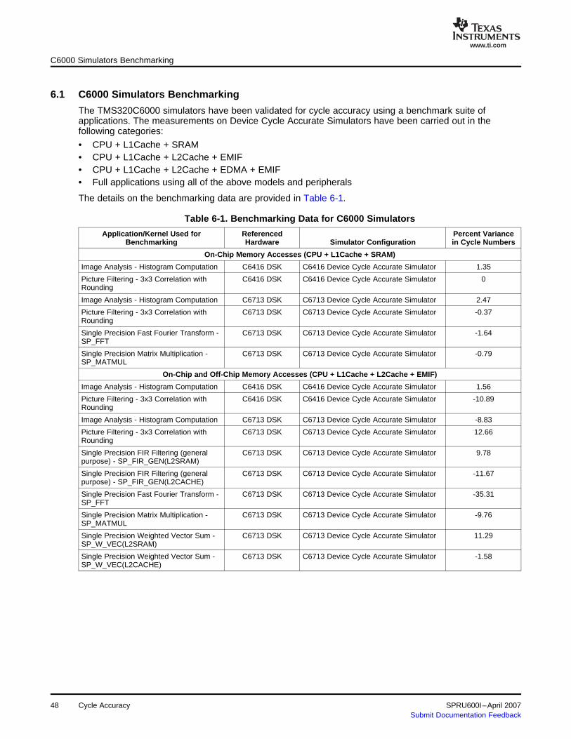
www.ti.com
6.1 C6000 Simulators Benchmarking
C6000 Simulators Benchmarking
The TMS320C6000 simulators have been validated for cycle accuracy using a benchmark suite ofapplications. The measurements on Device Cycle Accurate Simulators have been carried out in thefollowing categories:
• CPU + L1Cache + SRAM• CPU + L1Cache + L2Cache + EMIF• CPU + L1Cache + L2Cache + EDMA + EMIF• Full applications using all of the above models and peripherals
The details on the benchmarking data are provided in Table 6-1.
Table 6-1. Benchmarking Data for C6000 Simulators
Application/Kernel Used for Referenced Percent VarianceBenchmarking Hardware Simulator Configuration in Cycle Numbers
On-Chip Memory Accesses (CPU + L1Cache + SRAM)
Image Analysis - Histogram Computation C6416 DSK C6416 Device Cycle Accurate Simulator 1.35
Picture Filtering - 3x3 Correlation with C6416 DSK C6416 Device Cycle Accurate Simulator 0Rounding
Image Analysis - Histogram Computation C6713 DSK C6713 Device Cycle Accurate Simulator 2.47
Picture Filtering - 3x3 Correlation with C6713 DSK C6713 Device Cycle Accurate Simulator -0.37Rounding
Single Precision Fast Fourier Transform - C6713 DSK C6713 Device Cycle Accurate Simulator -1.64SP_FFT
Single Precision Matrix Multiplication - C6713 DSK C6713 Device Cycle Accurate Simulator -0.79SP_MATMUL
On-Chip and Off-Chip Memory Accesses (CPU + L1Cache + L2Cache + EMIF)
Image Analysis - Histogram Computation C6416 DSK C6416 Device Cycle Accurate Simulator 1.56
Picture Filtering - 3x3 Correlation with C6416 DSK C6416 Device Cycle Accurate Simulator -10.89Rounding
Image Analysis - Histogram Computation C6713 DSK C6713 Device Cycle Accurate Simulator -8.83
Picture Filtering - 3x3 Correlation with C6713 DSK C6713 Device Cycle Accurate Simulator 12.66Rounding
Single Precision FIR Filtering (general C6713 DSK C6713 Device Cycle Accurate Simulator 9.78purpose) - SP_FIR_GEN(L2SRAM)
Single Precision FIR Filtering (general C6713 DSK C6713 Device Cycle Accurate Simulator -11.67purpose) - SP_FIR_GEN(L2CACHE)
Single Precision Fast Fourier Transform - C6713 DSK C6713 Device Cycle Accurate Simulator -35.31SP_FFT
Single Precision Matrix Multiplication - C6713 DSK C6713 Device Cycle Accurate Simulator -9.76SP_MATMUL
Single Precision Weighted Vector Sum - C6713 DSK C6713 Device Cycle Accurate Simulator 11.29SP_W_VEC(L2SRAM)
Single Precision Weighted Vector Sum - C6713 DSK C6713 Device Cycle Accurate Simulator -1.58SP_W_VEC(L2CACHE)
48 Cycle Accuracy SPRU600I–April 2007Submit Documentation Feedback

www.ti.com
6.2 Notes on Cycle Accuracy
Notes on Cycle Accuracy
Table 6-1. Benchmarking Data for C6000 Simulators (continued)
Application/Kernel Used for Referenced Percent VarianceBenchmarking Hardware Simulator Configuration in Cycle Numbers
Memory Accesses using DMA (CPU + L1Cache + L2Cache + EDMA + EMIF)
Image Analysis - Histogram Computation C6416 DSK C6416 Device Cycle Accurate Simulator 1.80
Picture Filtering - 3x3 Correlation with C6416 DSK C6416 Device Cycle Accurate Simulator 9.49Rounding
Image Analysis - Histogram Computation C6713 DSK C6713 Device Cycle Accurate Simulator 0.87
Picture Filtering - 3x3 Correlation with C6713 DSK C6713 Device Cycle Accurate Simulator -0.55Rounding
Single Precision FIR Filtering (general C6713 DSK C6713 Device Cycle Accurate Simulator 9.67purpose) - SP_FIR_GEN
Single Precision Fast Fourier Transform - C6713 DSK C6713 Device Cycle Accurate Simulator 25.22SP_FFT
Single Precision Matrix Multiplication - C6713 DSK C6713 Device Cycle Accurate Simulator 9.58SP_MATMUL
Single Precision Weighted Vector Sum - C6713 DSK C6713 Device Cycle Accurate Simulator 6.64SP_W_VEC
Full Applications (CPU + L1Cache + L2Cache + EDMA + EMIF + Peripherals (McBSP, McASP))
Video & Imaging Application - MPEG2 C6416 DSK C6416 Device Cycle Accurate Simulator -0.12Decoder
Video & Imaging Application - H.263 C6416 DSK C6416 Device Cycle Accurate Simulator 1.46Decoder
Performance Audio Application - PA3 C6713 - PA3 C6713 Device Cycle Accurate Simulator -4.66Reference Board
Speech Application - PCM Voice Channel Access C6416 Device Cycle Accurate Simulator 1.02Communication
ProcessorEvaluation Platform
(C6416 daughtercard)
GSM AMR C6455 DSK C6455 Cycle Accurate Device Simulator -0.68
GSM AMR TCI6482 DSK TCI6482 Cycle Accurate Device Simulator -0.68
When comparing cycles between a simulator and a developer board (DSK/EVM/TEB), ensure thefollowing:
1. The Device Cycle Accurate Simulator chosen is appropriate for the desired target. For example, selectthe C6416 Device Cycle Accurate Simulator for a TMS320C6416 developer board. For more on thedifferent categories of simulators, see Choosing the Appropriate Simulator Configuration in CodeComposer Studio (SPRA864).
2. The ratio of the EMIF and CPU clocks on the simulator matches that on the respective developerboard. See Section 4.4 for information on configuring the simulator with the correct EMIF to CPU clockratio.
3. The EMIF settings of simulator match those of the developer board. Setting the EMIF registers with thesame value across the simulator and developer board, either in the emif_init gel file or in the program,will ensure this.
4. Cycle differences can arise due to emulation breakpoint handling. To get more accurate numbers, usetimers instead of profiler.
SPRU600I–April 2007 Cycle Accuracy 49Submit Documentation Feedback
IMPORTANT NOTICE
Texas Instruments Incorporated and its subsidiaries (TI) reserve the right to make corrections, modifications, enhancements,improvements, and other changes to its products and services at any time and to discontinue any product or service without notice.Customers should obtain the latest relevant information before placing orders and should verify that such information is current andcomplete. All products are sold subject to TI’s terms and conditions of sale supplied at the time of order acknowledgment.
TI warrants performance of its hardware products to the specifications applicable at the time of sale in accordance with TI’sstandard warranty. Testing and other quality control techniques are used to the extent TI deems necessary to support thiswarranty. Except where mandated by government requirements, testing of all parameters of each product is not necessarilyperformed.
TI assumes no liability for applications assistance or customer product design. Customers are responsible for their products andapplications using TI components. To minimize the risks associated with customer products and applications, customers shouldprovide adequate design and operating safeguards.
TI does not warrant or represent that any license, either express or implied, is granted under any TI patent right, copyright, maskwork right, or other TI intellectual property right relating to any combination, machine, or process in which TI products or servicesare used. Information published by TI regarding third-party products or services does not constitute a license from TI to use suchproducts or services or a warranty or endorsement thereof. Use of such information may require a license from a third party underthe patents or other intellectual property of the third party, or a license from TI under the patents or other intellectual property of TI.
Reproduction of information in TI data books or data sheets is permissible only if reproduction is without alteration and isaccompanied by all associated warranties, conditions, limitations, and notices. Reproduction of this information with alteration is anunfair and deceptive business practice. TI is not responsible or liable for such altered documentation.
Resale of TI products or services with statements different from or beyond the parameters stated by TI for that product or servicevoids all express and any implied warranties for the associated TI product or service and is an unfair and deceptive businesspractice. TI is not responsible or liable for any such statements.
TI products are not authorized for use in safety-critical applications (such as life support) where a failure of the TI product wouldreasonably be expected to cause severe personal injury or death, unless officers of the parties have executed an agreementspecifically governing such use. Buyers represent that they have all necessary expertise in the safety and regulatory ramificationsof their applications, and acknowledge and agree that they are solely responsible for all legal, regulatory and safety-relatedrequirements concerning their products and any use of TI products in such safety-critical applications, notwithstanding anyapplications-related information or support that may be provided by TI. Further, Buyers must fully indemnify TI and itsrepresentatives against any damages arising out of the use of TI products in such safety-critical applications.
TI products are neither designed nor intended for use in military/aerospace applications or environments unless the TI products arespecifically designated by TI as military-grade or "enhanced plastic." Only products designated by TI as military-grade meet militaryspecifications. Buyers acknowledge and agree that any such use of TI products which TI has not designated as military-grade issolely at the Buyer's risk, and that they are solely responsible for compliance with all legal and regulatory requirements inconnection with such use.
TI products are neither designed nor intended for use in automotive applications or environments unless the specific TI productsare designated by TI as compliant with ISO/TS 16949 requirements. Buyers acknowledge and agree that, if they use anynon-designated products in automotive applications, TI will not be responsible for any failure to meet such requirements.
Following are URLs where you can obtain information on other Texas Instruments products and application solutions:
Products Applications
Amplifiers amplifier.ti.com Audio www.ti.com/audio
Data Converters dataconverter.ti.com Automotive www.ti.com/automotive
DSP dsp.ti.com Broadband www.ti.com/broadband
Interface interface.ti.com Digital Control www.ti.com/digitalcontrol
Logic logic.ti.com Military www.ti.com/military
Power Mgmt power.ti.com Optical Networking www.ti.com/opticalnetwork
Microcontrollers microcontroller.ti.com Security www.ti.com/security
Low Power www.ti.com/lpw Telephony www.ti.com/telephonyWireless
Video & Imaging www.ti.com/video
Wireless www.ti.com/wireless
Mailing Address: Texas Instruments, Post Office Box 655303, Dallas, Texas 75265Copyright © 2007, Texas Instruments Incorporated