tm-t88vi technical reference guide...replacement of the tm-t88v appendix application development...
TRANSCRIPT
Technical Reference Guide
Describes features of the product.
Describes setup and installation of the product andperipherals.
Describes advanced usage methods for the product.
Describes how to control the printer and necessary information when you develop applications.
Describes how to handle the product.
Describes precautions for replacement.
Describes general specifications and character code tables.
M00102306Rev. G
Product Overview
Setup
Handling
Advanced Usage
Replacement of the TM-T88V
Appendix
Application Development Information
2
Cautions No part of this document may be reproduced, stored in a retrieval system, or transmitted in any form or by
any means, electronic, mechanical, photocopying, recording, or otherwise, without the prior written permission of Seiko Epson Corporation.
The contents of this document are subject to change without notice. Please contact us for the latest information.
While every precaution has been taken in the preparation of this document, Seiko Epson Corporationassumes no responsibility for errors or omissions.
Neither is any liability assumed for damages resulting from the use of the information contained herein. Neither Seiko Epson Corporation nor its affiliates shall be liable to the purchaser of this product or third
parties for damages, losses, costs, or expenses incurred by the purchaser or third parties as a result of:accident, misuse, or abuse of this product or unauthorized modifications, repairs, or alterations to thisproduct, or (excluding the U.S.) failure to strictly comply with Seiko Epson Corporation’s operating andmaintenance instructions.
Seiko Epson Corporation shall not be liable against any damages or problems arising from the use of anyoptions or any consumable products other than those designated as Original Epson Products or EpsonApproved Products by Seiko Epson Corporation.
TrademarksEPSON is a registered trademark of Seiko Epson Corporation.Exceed Your Vision and ESC/POS are registered trademarks or trademarks of Seiko Epson Corporation.Microsoft, Windows, and Windows Vista are registered trademarks of Microsoft Corporation in the UnitedStates and/or other countries.Wi-Fi®, WPATM, and WPA2TM are either registered trademarks or trademarks of Wi-Fi Alliance®.The Bluetooth® word mark and logos are registered trademarks owned by Bluetooth SIG, Inc. and any use ofsuch marks by Seiko Epson Corporation is under license.IOS is a trademark or registered trademark of Cisco in the U.S. and other countries and is used under license.Apple, Apple TV, Apple Watch, iPad, iPad Air, iPad Pro, iPhone, and Lightning are trademarks of Apple Inc.,registered in the U.S. and other countries. tvOS is a trademark of Apple Inc. iBeacon is a trademark of Apple Inc.Android and Google Play are trademarks of Google, Inc.All other trademarks are the property of their respective owners and used for identification purpose only.
ESC/POS® Command SystemEpson ESC/POS is a proprietary POS printer command system that includes patented or patent-pendingcommands. ESC/POS is compatible with most Epson POS printers and displays.ESC/POS is designed to reduce the processing load on the host computer in POS environments. It comprises aset of highly functional and efficient commands and also offers the flexibility to easily make future upgrades.
©Seiko Epson Corporation 2016-2018. All rights reserved.
3
For Safety
Key to Symbols
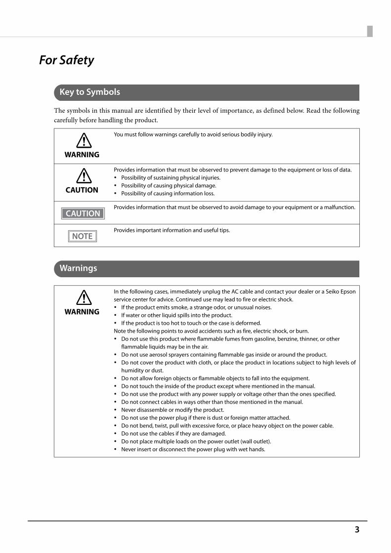
The symbols in this manual are identified by their level of importance, as defined below. Read the followingcarefully before handling the product.
Warnings
WARNING
You must follow warnings carefully to avoid serious bodily injury.
CAUTION
Provides information that must be observed to prevent damage to the equipment or loss of data. Possibility of sustaining physical injuries. Possibility of causing physical damage. Possibility of causing information loss.
Provides information that must be observed to avoid damage to your equipment or a malfunction.
Provides important information and useful tips.
WARNING
In the following cases, immediately unplug the AC cable and contact your dealer or a Seiko Epsonservice center for advice. Continued use may lead to fire or electric shock. If the product emits smoke, a strange odor, or unusual noises. If water or other liquid spills into the product. If the product is too hot to touch or the case is deformed.Note the following points to avoid accidents such as fire, electric shock, or burn. Do not use this product where flammable fumes from gasoline, benzine, thinner, or other
flammable liquids may be in the air. Do not use aerosol sprayers containing flammable gas inside or around the product. Do not cover the product with cloth, or place the product in locations subject to high levels of
humidity or dust. Do not allow foreign objects or flammable objects to fall into the equipment. Do not touch the inside of the product except where mentioned in the manual. Do not use the product with any power supply or voltage other than the ones specified. Do not connect cables in ways other than those mentioned in the manual. Never disassemble or modify the product. Do not use the power plug if there is dust or foreign matter attached. Do not bend, twist, pull with excessive force, or place heavy object on the power cable. Do not use the cables if they are damaged. Do not place multiple loads on the power outlet (wall outlet). Never insert or disconnect the power plug with wet hands.

4
Cautions
CAUTION
Note the following points to avoid injury or malfunction. Setup the product on a firm, stable, horizontal surface. Do not place heavy objects on top of the product. Never stand or lean on the product. Do not press your hands or fingers against the cutter when removing printed paper or loading/
replacing roll paper. Do not put your hands between the cover and the body of the product when opening/closing
the cover. Never attempt to repair the product yourself. Do not connect a telephone line to the drawer kick connector.To ensure safety, unplug this product before leaving it unused for an extended period.
5
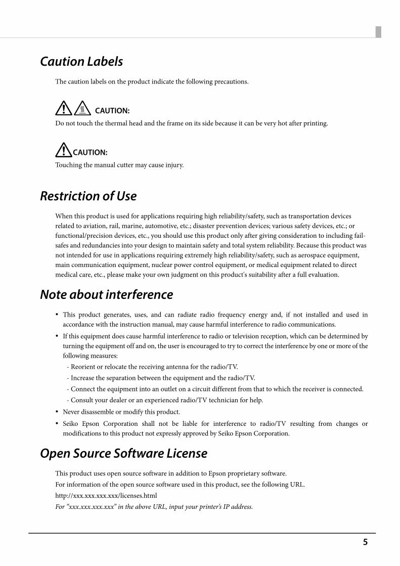
Caution LabelsThe caution labels on the product indicate the following precautions.
CAUTION: Do not touch the thermal head and the frame on its side because it can be very hot after printing.
CAUTION:Touching the manual cutter may cause injury.
Restriction of UseWhen this product is used for applications requiring high reliability/safety, such as transportation devices related to aviation, rail, marine, automotive, etc.; disaster prevention devices; various safety devices, etc.; or functional/precision devices, etc., you should use this product only after giving consideration to including fail-safes and redundancies into your design to maintain safety and total system reliability. Because this product was not intended for use in applications requiring extremely high reliability/safety, such as aerospace equipment, main communication equipment, nuclear power control equipment, or medical equipment related to direct medical care, etc., please make your own judgment on this product's suitability after a full evaluation.
Note about interference This product generates, uses, and can radiate radio frequency energy and, if not installed and used in
accordance with the instruction manual, may cause harmful interference to radio communications. If this equipment does cause harmful interference to radio or television reception, which can be determined by
turning the equipment off and on, the user is encouraged to try to correct the interference by one or more of thefollowing measures:
- Reorient or relocate the receiving antenna for the radio/TV.- Increase the separation between the equipment and the radio/TV.- Connect the equipment into an outlet on a circuit different from that to which the receiver is connected.- Consult your dealer or an experienced radio/TV technician for help.
Never disassemble or modify this product. Seiko Epson Corporation shall not be liable for interference to radio/TV resulting from changes or
modifications to this product not expressly approved by Seiko Epson Corporation.
Open Source Software LicenseThis product uses open source software in addition to Epson proprietary software.For information of the open source software used in this product, see the following URL.http://xxx.xxx.xxx.xxx/licenses.htmlFor “xxx.xxx.xxx.xxx” in the above URL, input your printer’s IP address.
6
About this Manual
Aim of the Manual
This manual provides developers/engineers with all the necessary information for design, development andinstallation of a POS system, and also design and development of a printer application.
Manual Content
The manual is made up of the following sections:
Chapter 1 Product Overview
Chapter 2 Setup
Chapter 3 Advanced Usage
Chapter 4 Application Development Information
Chapter 5 Handling
Chapter 6 Replacement of the TM-T88V
Appendix Product Specifications
Specifications of Interfaces and Connectors
Bluetooth Low Energy Technology Advertising
Character Code Tables
7
Contents■ For Safety..................................................................................................................................3
Key to Symbols.................................................................................................................................................................... 3Warnings ............................................................................................................................................................................... 3Cautions................................................................................................................................................................................. 4
■ Caution Labels .........................................................................................................................5
■ Restriction of Use ....................................................................................................................5
■ Note about interference ........................................................................................................5
■ Open Source Software License.............................................................................................5
■ About this Manual ..................................................................................................................6
Aim of the Manual ............................................................................................................................................................. 6Manual Content .................................................................................................................................................................. 6
■ Contents....................................................................................................................................7
Product Overview ..........................................................................................13
■ Features ................................................................................................................................. 13
■ Product Configurations ...................................................................................................... 15
Models..................................................................................................................................................................................15Accessories .........................................................................................................................................................................15
■ Part Names and Functions ................................................................................................. 17Control Panel .....................................................................................................................................................................18Connectors .........................................................................................................................................................................19Online and Offline............................................................................................................................................................20
■ Status and Errors .................................................................................................................. 21Error Status .........................................................................................................................................................................21Status Display ....................................................................................................................................................................22
■ NV Memory ........................................................................................................................... 24
NV Graphics Memory......................................................................................................................................................24User NV Memory ..............................................................................................................................................................24Memory Switches.............................................................................................................................................................24R/E (Receipt Enhancement)..........................................................................................................................................24Maintenance Counter.....................................................................................................................................................25Web contents.....................................................................................................................................................................25
■ Simple Setup for Wireless LAN .......................................................................................... 26
■ Useful Functions for Smart Devices.................................................................................. 27
NFC Tag ................................................................................................................................................................................27QR Code...............................................................................................................................................................................27
8
■ Printing Using Multiple Interfaces .................................................................................... 28
Setup............................................................................................................... 29
■ Flow of Setup ........................................................................................................................ 29
■ Installing the Printer............................................................................................................ 30
Important Notes on Horizontal Installation........................................................................................................... 30Important Notes on Wall Hanging ............................................................................................................................ 30
■ Adjusting the Paper Roll Near-End Sensor...................................................................... 31
■ Connecting the AC adapter................................................................................................ 32
Connecting the AC adapter ......................................................................................................................................... 32
■ Connecting the Printer to the Host................................................................................... 33USB Interface..................................................................................................................................................................... 33Ethernet Interface............................................................................................................................................................ 33Wireless LAN Interface ................................................................................................................................................... 34Bluetooth Interface ......................................................................................................................................................... 36Serial Interface.................................................................................................................................................................. 40Parallel Interface .............................................................................................................................................................. 40USB Plus Power Interface.............................................................................................................................................. 40
■ Connecting the Cash Drawer ............................................................................................. 41
Connecting the drawer kick cable............................................................................................................................. 42
■ Setting the Built-in Buzzer (for Model with a Built-in Buzzer)43
■ Connecting the Optional External Buzzer....................................................................... 44
Attachment Position....................................................................................................................................................... 44
■ Connecting the Optional Wireless LAN Unit ................................................................... 45
■ Connecting the Optional Customer Display ................................................................... 45
■ Attaching the Connector Cover......................................................................................... 46
■ Arranging the Cables........................................................................................................... 48
■ Attaching the Power Switch Cover ................................................................................... 50
■ Changing the Paper Width ................................................................................................. 51
■ RTC Settings .......................................................................................................................... 52
Advanced Usage............................................................................................ 53
■ Setting the DIP Switches..................................................................................................... 53
Setting Procedure............................................................................................................................................................ 53When a Serial Interface is Connected....................................................................................................................... 55When Another Interface is Connected .................................................................................................................... 57Selecting the Print Density (DIP Switches 2-3/2-4).............................................................................................. 58Selecting the BUSY Status ............................................................................................................................................ 58

9
■ Software Settings................................................................................................................. 59Functions.............................................................................................................................................................................61
■ Setting/Checking Modes .................................................................................................... 68
Self-test Mode ...................................................................................................................................................................70NV Graphics Information Print Mode........................................................................................................................70Receipt Enhancement Information Print Mode ....................................................................................................71Software Setting Mode ..................................................................................................................................................72Restore Default Values Mode.......................................................................................................................................74Interface Setup Mode.....................................................................................................................................................76TM-Intelligent Settings Information Print Mode ..................................................................................................78Peripheral Device Information Print Mode .............................................................................................................78Hexadecimal Dumping Mode .....................................................................................................................................79
■ Printing a Status Sheet........................................................................................................ 80
■ Resetting the Interface Settings ....................................................................................... 83
■ TM-Intelligent Function ...................................................................................................... 84
Server direct print ............................................................................................................................................................84Web server ..........................................................................................................................................................................84Spooler and Print Forwarding .....................................................................................................................................85
Application Development Information.......................................................87
■ Controlling the Printer ........................................................................................................ 87
ePOS-Print XML.................................................................................................................................................................87ESC/POS...............................................................................................................................................................................87
■ Controlling the Cash Drawer.............................................................................................. 88
■ Controlling the Built-in Buzzer .......................................................................................... 89
■ Controlling the Optional External Buzzer ....................................................................... 90
■ Software................................................................................................................................. 91Development Kits ............................................................................................................................................................91Drivers ..................................................................................................................................................................................92Utilities .................................................................................................................................................................................92Others...................................................................................................................................................................................93Download ...........................................................................................................................................................................93
■ Application Development and Distribution for iOS...................................................... 94
Handling .........................................................................................................95
■ Installing and Replacing Roll Paper.................................................................................. 95
■ Removing Jammed Paper .................................................................................................. 98
■ If Roll Paper Cover does not Open .................................................................................. 100
■ Cleaning the Printer........................................................................................................... 101
Cleaning the Printer Case........................................................................................................................................... 101

10
Cleaning the Thermal Head/Platen Roller ............................................................................................................101
■ Preparing for Transport.....................................................................................................102
Replacement of the TM-T88V..................................................................... 103
■ Compatibility ......................................................................................................................103
Printing..............................................................................................................................................................................103Print Density ....................................................................................................................................................................103Number of Head Energizing Parts ...........................................................................................................................103Printable Area (for 80 mm Width Paper)................................................................................................................103Cutting Method..............................................................................................................................................................103Manual Paper Feed .......................................................................................................................................................103Receive Buffer .................................................................................................................................................................104Memory Capacity ..........................................................................................................................................................104Electrical Characteristics .............................................................................................................................................104DIP Switches ....................................................................................................................................................................104Printer Status...................................................................................................................................................................104Logo Registration ..........................................................................................................................................................104Driver Compatibility .....................................................................................................................................................104USB Low Power Consumption Mode .....................................................................................................................104Maintenance Counter ..................................................................................................................................................105Buzzer ................................................................................................................................................................................105Power Supply Box..........................................................................................................................................................105Overall Dimensions.......................................................................................................................................................106
■ Additional Functions and Functional Improvements ................................................. 107Print Speed.......................................................................................................................................................................107Interface ............................................................................................................................................................................107SimpleAP Function........................................................................................................................................................107NFC......................................................................................................................................................................................107Epson TM Utility for iOS/Android.............................................................................................................................107Software Settings ..........................................................................................................................................................108TM-Intelligent function ...............................................................................................................................................108
Appendix ...................................................................................................... 109
■ Product Specifications ......................................................................................................109
Printing Specifications .................................................................................................................................................110Character Specifications..............................................................................................................................................111Printable Area..................................................................................................................................................................112Printing and Cutting Positions..................................................................................................................................114Paper Specifications .....................................................................................................................................................115Electrical Characteristics .............................................................................................................................................116Environmental Conditions .........................................................................................................................................117External Dimensions and Mass.................................................................................................................................118Network Printer ..............................................................................................................................................................120
■ Specifications of Interfaces and Connectors ................................................................ 121
USB Interface...................................................................................................................................................................121

11
Ethernet Interface ......................................................................................................................................................... 122Wi-Fi Interface................................................................................................................................................................. 123Bluetooth Interface....................................................................................................................................................... 125RS-232 Serial Interface................................................................................................................................................. 128IEEE 1284 Parallel Interface........................................................................................................................................ 131NFC Tag ............................................................................................................................................................................. 133
■ Bluetooth Low Energy Technology Advertising........................................................... 134
Introduction .................................................................................................................................................................... 134Dongle specifications .................................................................................................................................................. 134Procedure......................................................................................................................................................................... 134Changing the Bluetooth Low Energy Technology Advertising Packet...................................................... 135
■ Character Code Tables....................................................................................................... 146

12

13
Chapter 1 Product Overview
1
Product OverviewThis chapter describes features of the product.
Features
Printing High speed printing (350 mm/s maximum). Shifting from 80 mm width paper printing to 58 mm width paper printing is available. Multi-tone graphic printing.
Handling Easy drop-in paper loading
Software TM-Intelligent function is equipped.
Supports Server Direct Print that sends a request for print data from the product to the Web server atregular intervals.
Since print data can be saved in the spooler, applications can be released from processing print jobsregardless of the printer status.
When a network printer is registered, print forwarding process can be realized. Also, if the printer is notready to print, you can print from another printer.
Equipped with Web server that supports the scripting language "PHP" and database "SQLite3". Command protocol is based on the ESC/POS Proprietary Command System. OPOS ADK, OPOS ADK for .NET, JavaPOS ADK, and Windows printer drivers are available. In addition to supporting several kinds of bar code printing, DS1 DataBar printing and two-dimensional
symbol (PDF417, QR code, MaxiCode, Composite Symbology) printing are possible. A maintenance counter function is supported. Various utility software are available. A utility for iOS/AndroidTM (Epson TM Utility for iOS/Android) for making printer settings is also provided.
Environment Compliant with International ENERGY STAR Program. Paper saving function is available.
Functions NFC tag built into the printer unit for printing to a touched printer. Printing triggered by bar code scan by smart device camera.

14
Supports printing using multiple interfaces. Enables HTTPS communication.
Others Various interface models are available. Optional Wireless LAN cable set, customer display, external buzzer, and interface boards are available. Optional wall hanging bracket is available to attach the printer to a wall. The TM-T88VI Software & Documents Disc containing drivers, utility, and manuals is available.
* It may not be supplied depending on the model.

15
Chapter 1 Product Overview
1
Product Configurations
Models
Standard model: Ethernet interface, built-in USB interface , serial interface Parallel model: Ethernet interface, built-in USB interface , parallel interface USB Plus Power model: Ethernet interface, built-in USB interface , USB Plus Power Interface Wi-Fi® model: Ethernet interface, built-in USB interface , Wireless LAN interface Bluetooth® model: Ethernet interface, built-in USB interface, Bluetooth interface
Accessories
Included Roll paper (for operation check) Power switch cover Connector cover Screw for attaching the Connector cover (x1) Bottom cover for the Connector cover Screw for attaching the Bottom cover for the Connector cover (x2) Roll paper guide Screw for attaching the roll paper guide (x1) TM-T88VI Software & Documents Disc (drivers, utilities, and documentation) * AC adapter* AC cable* Warranty certificate* Setup Guide* May not be included depending on the model.
Options AC adapter AC cable Power supply box (Model: OT-BX88VI) Wall hanging bracket (Model: WH-10) Interface boards (UB series)* Optional external buzzer (Model: OT-BZ20)
CAUTION
Never use interface board with a buzzer function on this product.Otherwise, the printer or the interface board may be damaged.The name of interface boards with a buzzer function has “A” at the end.Example) UB-E**A, UB-R**A (*: alphanumeric character)

16
Wireless LAN cable set (Model: OT-WL02/OT-WL05) Customer display (Model: DM-D30, DM-D110)* UB-E**A and UB-R**A cannot be used.

17
Chapter 1 Product Overview
1
Part Names and Functions
.
1 NFC Tag A mark is printed here to indicate the position of the NFC tag. To establish communicationwith an NFC device, bring the device close to this mark. For details on functions that use theNFC tag, refer to "Useful Functions for Smart Devices" on page 27.
There is no data rewriting function.
Use Epson ePOS SDK to build this function into your application.
2 Roll paper cover Open this cover to install/replace the roll paper.
3 Manual cutter Use this cutter when you cut the roll paper manually.
4 Cutter cover Open this cover to unlock the autocutter blade when the roll paper cover does not open dueto a paper jam.
5 Power switch Turns the printer on or off.
6 Power switch cover Install the power switch cover onto the printer to prevent inadvertent changing of thepower switch, to prevent tampering, and to improve the appearance of the printer.
To operate the power switch, insert an object with a pointed tip such as a ballpoint pen intothe hole on the power switch cover.
For attaching the power switch cover, refer "Attaching the Power Switch Cover" on page 50.
7 Connector cover Use the printer with this cover attached to protect cables.
8 Cover open button Use this button to open the roll paper cover.
9 Feed button Pressing this button once feeds roll paper for one line. Hold down this button to continuefeeding roll paper.
10 Control Panel For details on LED, see "Control Panel" on page 18.
11 Dip switch cover Open the cover to view the dip switches for communication settings.
11
2
4
5
6
7
1
38910
18
Control Panel
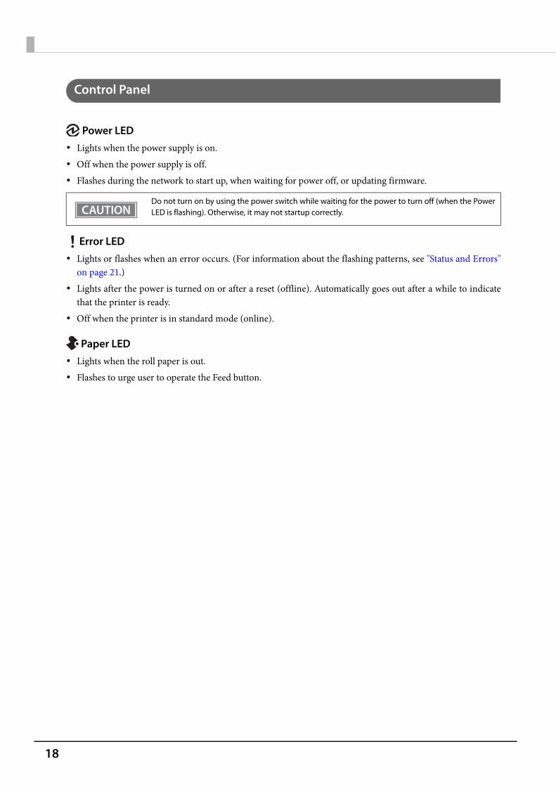
Power LED Lights when the power supply is on. Off when the power supply is off. Flashes during the network to start up, when waiting for power off, or updating firmware.
Error LED Lights or flashes when an error occurs. (For information about the flashing patterns, see "Status and Errors"
on page 21.) Lights after the power is turned on or after a reset (offline). Automatically goes out after a while to indicate
that the printer is ready. Off when the printer is in standard mode (online).
Paper LED Lights when the roll paper is out. Flashes to urge user to operate the Feed button.
Do not turn on by using the power switch while waiting for the power to turn off (when the PowerLED is flashing). Otherwise, it may not startup correctly.

19
Chapter 1 Product Overview
1
Connectors
All connectors are located on the lower rear of the printer.
The installed interface varies depending on the model. Do not insert a Type-B USB connector into the LAN connector or the drawer kick connector. If it
is inserted, the connector, printer, and the system may malfunction. If using the drawer kick connector and a serial/parallel connector simultaneously, we recommend
using either of the cables below to prevent the cables from interfering with one another.* Flat-type drawer kick cable* Serial/parallel cable with a connector (from the tip to the screw) that is within 34 mm {1.34"}.
1 Drawer kick connector Connects the cash drawer or the optional external buzzer.See "Connecting the Cash Drawer" on page 41, and "Connecting the Optional ExternalBuzzer" on page 44.
2 Ethernet connector Connects the 10BASE-T/100BASE-TX ethernet cable.
3 Serial interface Connects the serial cable for connecting to a computer.
4 Parallel interface Connects the parallel cable for connecting to a computer.
5 USB Plus Power Interface Connects the USB Plus Power cable for connecting to a computer.
6 Power supply connector Connect the AC adapter.See "Connecting the AC adapter" on page 32.
7 USB connector Use only for connecting optional Wireless LAN unit and customer display.
8 USB connector (Type B)
Connects the USB cable for connecting to a computer.See "Connecting the Printer to the Host" on page 33.
Within 34 mm {1.34"}
2
1 3 4
6 7 85

20
Online and Offline
OnlineThe printer is online and ready for normal printing unless there is a reason to go offline.
OfflineThe printer automatically goes offline under the following conditions: While the printer power is turning on/off While a self-test is running While roll paper is fed using the Feed button When the printer stops printing due to a paper end (when the paper out detector detected the paper out) During an operation standby state When an error has occurred (See "Status and Errors" on page 21) While the roll paper cover is open
21
Chapter 1 Product Overview
1
Status and Errors
Error Status
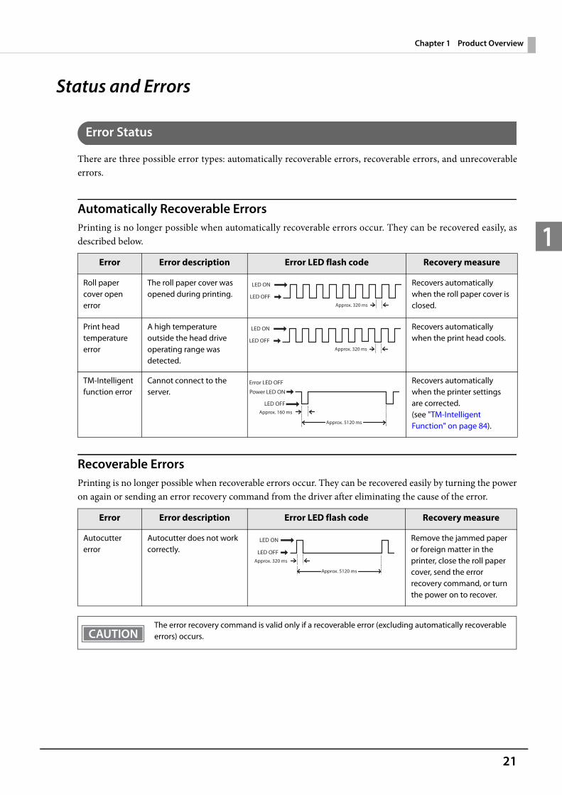
There are three possible error types: automatically recoverable errors, recoverable errors, and unrecoverableerrors.
Automatically Recoverable ErrorsPrinting is no longer possible when automatically recoverable errors occur. They can be recovered easily, asdescribed below.
Recoverable ErrorsPrinting is no longer possible when recoverable errors occur. They can be recovered easily by turning the poweron again or sending an error recovery command from the driver after eliminating the cause of the error.
Error Error description Error LED flash code Recovery measure
Roll paper cover open error
The roll paper cover was opened during printing.
Recovers automatically when the roll paper cover is closed.
Print head temperature error
A high temperature outside the head drive operating range was detected.
Recovers automatically when the print head cools.
TM-Intelligent function error
Cannot connect to the server.
Recovers automatically when the printer settings are corrected.(see "TM-Intelligent Function" on page 84).
Error Error description Error LED flash code Recovery measure
Autocutter error
Autocutter does not work correctly.
Remove the jammed paper or foreign matter in the printer, close the roll paper cover, send the error recovery command, or turn the power on to recover.
The error recovery command is valid only if a recoverable error (excluding automatically recoverable errors) occurs.
LED ON
LED OFFApprox. 320 ms
LED ON
LED OFFApprox. 320 ms
Power LED ON
LED OFFApprox. 160 ms
Approx. 5120 ms
Error LED OFF
LED ON
LED OFFApprox. 320 ms
Approx. 5120 ms
22
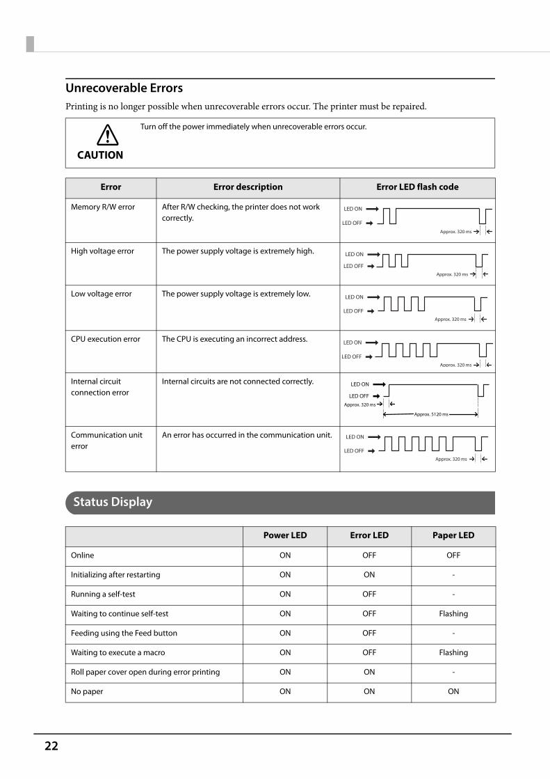
Unrecoverable ErrorsPrinting is no longer possible when unrecoverable errors occur. The printer must be repaired.
Status Display
CAUTION
Turn off the power immediately when unrecoverable errors occur.
Error Error description Error LED flash code
Memory R/W error After R/W checking, the printer does not work correctly.
High voltage error The power supply voltage is extremely high.
Low voltage error The power supply voltage is extremely low.
CPU execution error The CPU is executing an incorrect address.
Internal circuit connection error
Internal circuits are not connected correctly.
Communication unit error
An error has occurred in the communication unit.
Power LED Error LED Paper LED
Online ON OFF OFF
Initializing after restarting ON ON -
Running a self-test ON OFF -
Waiting to continue self-test ON OFF Flashing
Feeding using the Feed button ON OFF -
Waiting to execute a macro ON OFF Flashing
Roll paper cover open during error printing ON ON -
No paper ON ON ON
LED ON
LED OFFApprox. 320 ms
LED ON
LED OFFApprox. 320 ms
LED ON
LED OFFApprox. 320 ms
LED ON
LED OFFApprox. 320 ms
LED ON
LED OFFApprox. 320 ms
Approx. 5120 ms
LED ON
LED OFFApprox. 320 ms

23
Chapter 1 Product Overview
1
-: Changes depending on whether or not paper is detected.
Paper near end ON OFF ON
While updating firmware Flashing OFF OFF
Power off standing by Flashing OFF OFF
Waiting to print status sheet ON ON Flashing
Power LED Error LED Paper LED
24
NV MemoryThe printer's NV memory (Non-Volatile Memory) stores data even after the printer power is turned off. NVmemory contains the following memory areas for the user: NV graphics memory User NV memory Memory switches R/E (Receipt Enhancement) Maintenance counter Web contents
NV Graphics Memory
Graphics, such as shop logos to be printed on receipts, can be stored. Even with a serial interface model whosecommunication speed is low, high speed graphics printing is possible.Use the Setup Utilities to register graphics.You can confirm the registered graphics in the NV graphics information print mode.
User NV Memory
You can store and read text data for multiple purposes, such as for storing a note including customizing ormaintenance information of the printer.
Memory Switches
With the memory switches, which are software switches for the printer, you can configure various settings of theprinter. For information about the memory switch, see "Software Settings" on page 59.
R/E (Receipt Enhancement)
Graphics, such as shop logos to be printed on top or bottom of receipts can be registered.Use the Setup Utilities to register graphics.
CAUTION
NV memory can be rewritten about 100,000 times. As a guide, NV memory rewriting should be 10times or less a day when you program applications.
For detailed information about the Epson TM-T88VI Utility for Windows, see the TM-T88VI UtilityUser’s Manual.
For information about how to use the NV graphics information print mode, see "NV GraphicsInformation Print Mode" on page 70.

25
Chapter 1 Product Overview
1
Maintenance Counter
With this function, printer information, such as the number of lines printed, the number of autocuts, andprinter operation time after the printer starts working, is automatically stored in NV memory.
Web contents
The region for Web servers.
You can also check the head running length and number of times of autocutting with the self-test (see"Self-test Mode" on page 70).
26
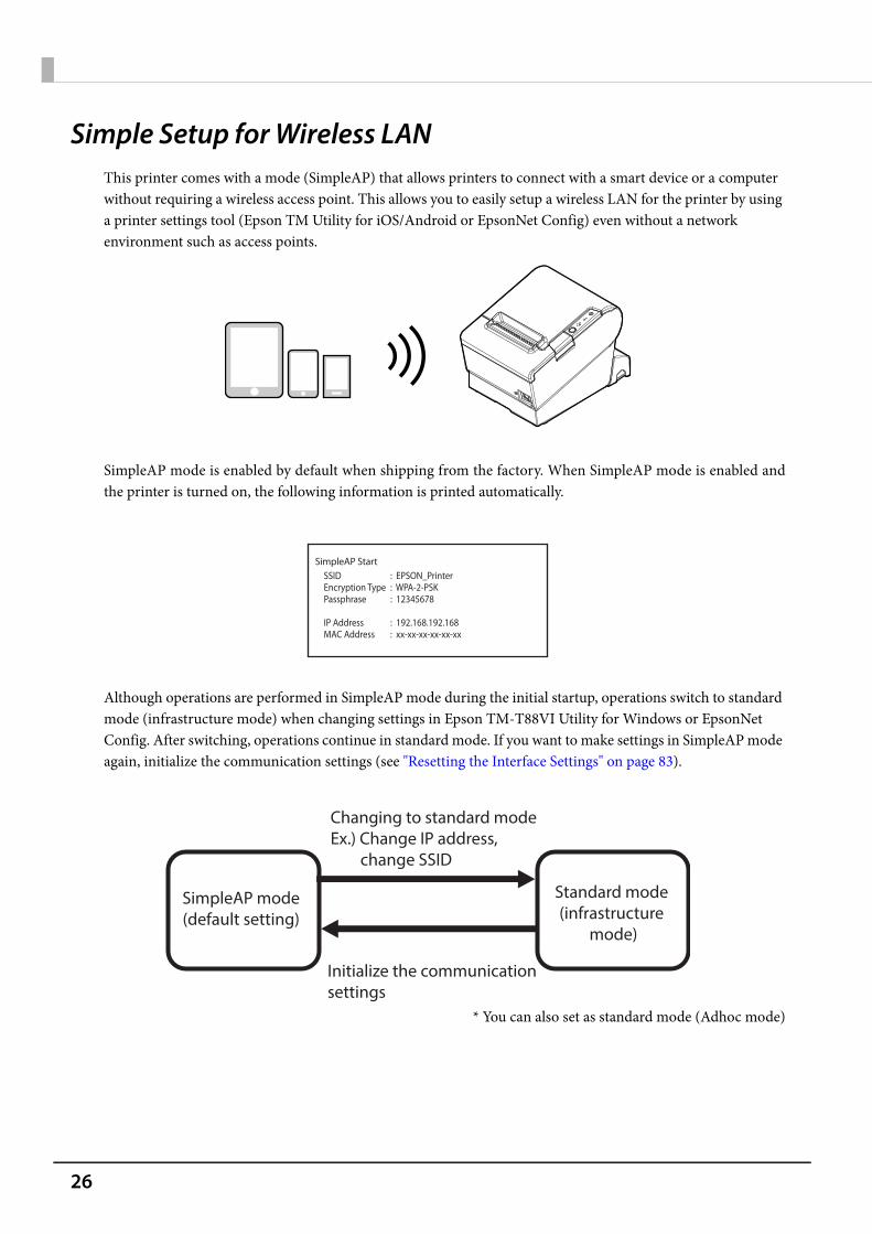
Simple Setup for Wireless LANThis printer comes with a mode (SimpleAP) that allows printers to connect with a smart device or a computer without requiring a wireless access point. This allows you to easily setup a wireless LAN for the printer by using a printer settings tool (Epson TM Utility for iOS/Android or EpsonNet Config) even without a network environment such as access points.
SimpleAP mode is enabled by default when shipping from the factory. When SimpleAP mode is enabled andthe printer is turned on, the following information is printed automatically.
Although operations are performed in SimpleAP mode during the initial startup, operations switch to standard mode (infrastructure mode) when changing settings in Epson TM-T88VI Utility for Windows or EpsonNet Config. After switching, operations continue in standard mode. If you want to make settings in SimpleAP mode again, initialize the communication settings (see "Resetting the Interface Settings" on page 83).
* You can also set as standard mode (Adhoc mode)
SimpleAP StartSSIDEncryption TypePassphrase
IP AddressMAC Address
: EPSON_Printer: WPA-2-PSK: 12345678
: 192.168.192.168: xx-xx-xx-xx-xx-xx
Standard mode(infrastructure
mode)
SimpleAP mode(default setting)
Changing to standard modeEx.) Change IP address, change SSID
Initialize the communication settings
27
Chapter 1 Product Overview
1
Useful Functions for Smart DevicesYou can easily connect this product to the network by using the NFC tag built-in to the printer or the QR codeprinted on the status sheet.
NFC Tag
Bring a smart device that supports NFC close to the NFC tag to acquire the printer information (informationfor specifying the device).Specify the target printer using the acquired information to connect to the network.
QR Code
Capture the QR code printed on the status sheet with the camera on your smart device to acquire the printerinformation (information for specifying the device).Specify the target printer using the acquired information to connect to the network.
Programming using Epson ePOS SDK is required to use these functions. These functions arecreated by combining NFC touch and QR code capturing operations and the target printerspecifications using Printer Easy Select API.See the "Epson ePOS SDK for Android/iOS User's Manual" and the Epson ePOS SDK sampleprogram for more details. The sample program also contains a sample implementation method forreading an NFC tag and capturing a QR code.
You can try a demo of these functions by using Epson TM Utility for iOS/Android.
28
Printing Using Multiple InterfacesIn printers with multiple interfaces, you can use all interfaces without any limitations on which interface is to beused. You can use this function to temporarily connect a smart device to a nearby printer and print.
The printer provides each interface with an independent receive buffer and switches the active interfacedepending on the priority, while handling data in each receive buffer.
You can set one interface for the main connection. Data received from the main connection interface is handledwith the highest priority.By default, the interface that receives the first data transfer is set as the main connection interface; however, youcan select the main connection interface in advance.
In the status where all receive buffers are empty for more than the set time (1 second by default), interfaceswitching is enabled. The interface that receives the data in this status becomes active.
You cannot use wired and wireless LANs at the same time. When a LAN cable is connected, wirelessLAN is disabled.
You can select the main connection interface and set the time to enable interface switching from thesoftware settings. For details on software settings, see "Software Settings" on page 59.
29
Chapter 2 Setup
2
SetupThis chapter describes setup and installation of the product and peripherals.
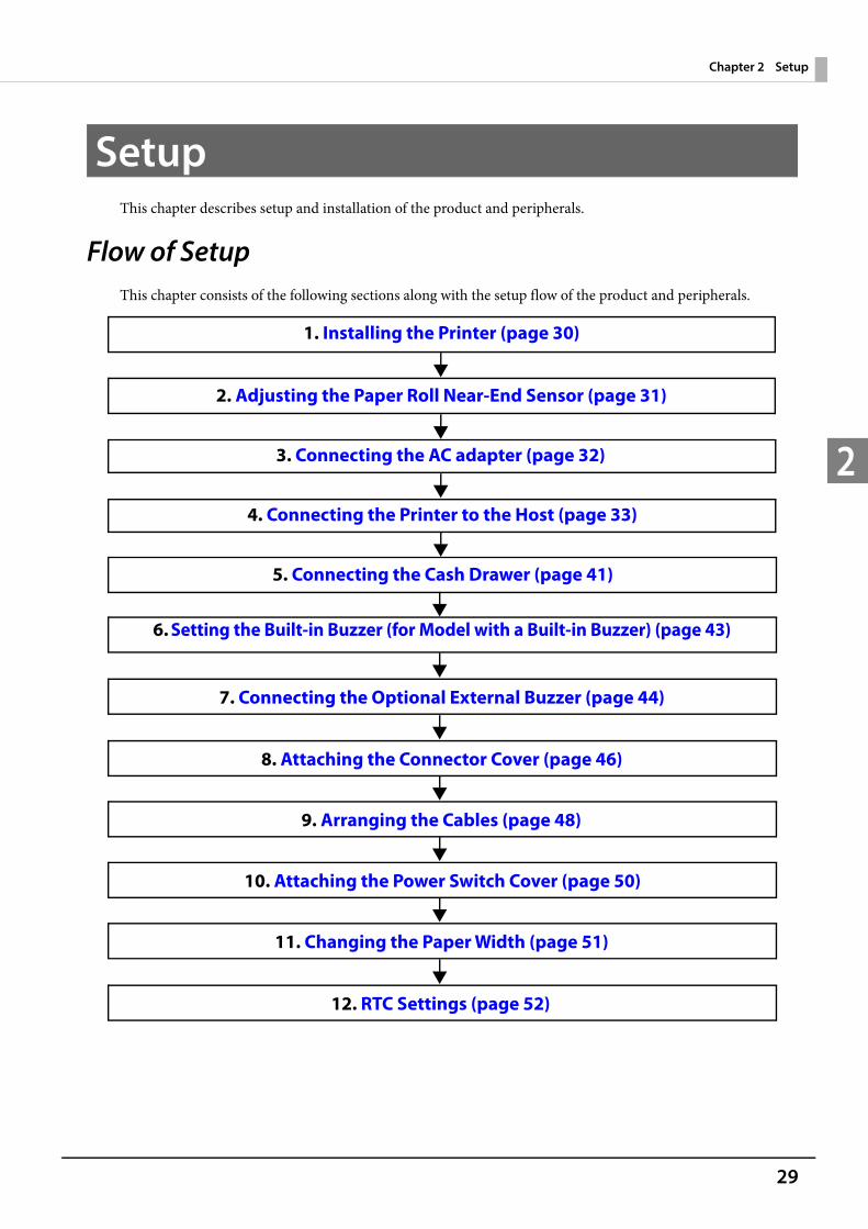
Flow of SetupThis chapter consists of the following sections along with the setup flow of the product and peripherals.
2. Adjusting the Paper Roll Near-End Sensor (page 31)
5. Connecting the Cash Drawer (page 41)
4. Connecting the Printer to the Host (page 33)
6. Setting the Built-in Buzzer (for Model with a Built-in Buzzer) (page 43)
1. Installing the Printer (page 30)
7. Connecting the Optional External Buzzer (page 44)
8. Attaching the Connector Cover (page 46)
9. Arranging the Cables (page 48)
10. Attaching the Power Switch Cover (page 50)
3. Connecting the AC adapter (page 32)
11. Changing the Paper Width (page 51)
12. RTC Settings (page 52)
30
Installing the PrinterYou can install this printer horizontally. With an optional hanging bracket (WH-10), you can also attach theprinter to a wall.
Important Notes on Horizontal Installation
The printer must be installed horizontally on a flat surface (not tilted). Do not place the printer in dusty locations. Do not catch cables or place foreign matter under the printer.
Important Notes on Wall Hanging
You need to perform the following tasks to install the printer on a wall. For more details, see the installationmanual for the optional wall hanging bracket (WH-10). Installing the roll-paper stoppers Changing the location of the roll paper near-end sensor Attaching the connector cover Attaching the wall hanging bracket (WH-10)For the other notes, see the installation manual for the optional wall hanging bracket (WH-10).
Be sure to attach the connector cover when you install the printer on a wall using the wall hangingbracket.
When installing on a wall using a wall mounting bracket, the status of the wireless signal for thewireless LAN unit may decline. In this situation, use an extension cable.

31
Chapter 2 Setup
2
Adjusting the Paper Roll Near-End SensorBelow are two situations where a roll paper NE sensor adjustment is required. To adjust the detection position to suit the diameter of the roll paper core used. To adjust the detection position of remaining amount of paper.
Follow the steps below to adjust the roll paper near-end detector.
1 Open the roll paper cover, and remove the roll paper.
2 Loosen the adjustment screw fastening the sensor, and align the upper edge of thepositioning plate with the adjustment position.
3 Tighten the adjustment screw.
4 After adjustment, make sure that the detection lever operates smoothly.
Since roll paper cores vary slightly in shape, depending on paper roll design and manufacturing tolerances, it is impossible to detect the remaining paper exactly.
Use roll paper with a core inner diameter of 12 mm {0.47"} and outer diameter of 18 mm {0.71"} sothat the NE sensor can detect the remaining paper as accurately as possible.
Adjustment positionRemaining amount of paper
(outer diameter: mm)
Upper Approx. 27 {1.06"}
Lower (Default setting) Approx. 23 {0.97"}
Detection lever
Positioning plate
Adjustment screw
Adjustment screw
Positioning plate
Detection lever
For wall-hanging
For horizontal installation
32
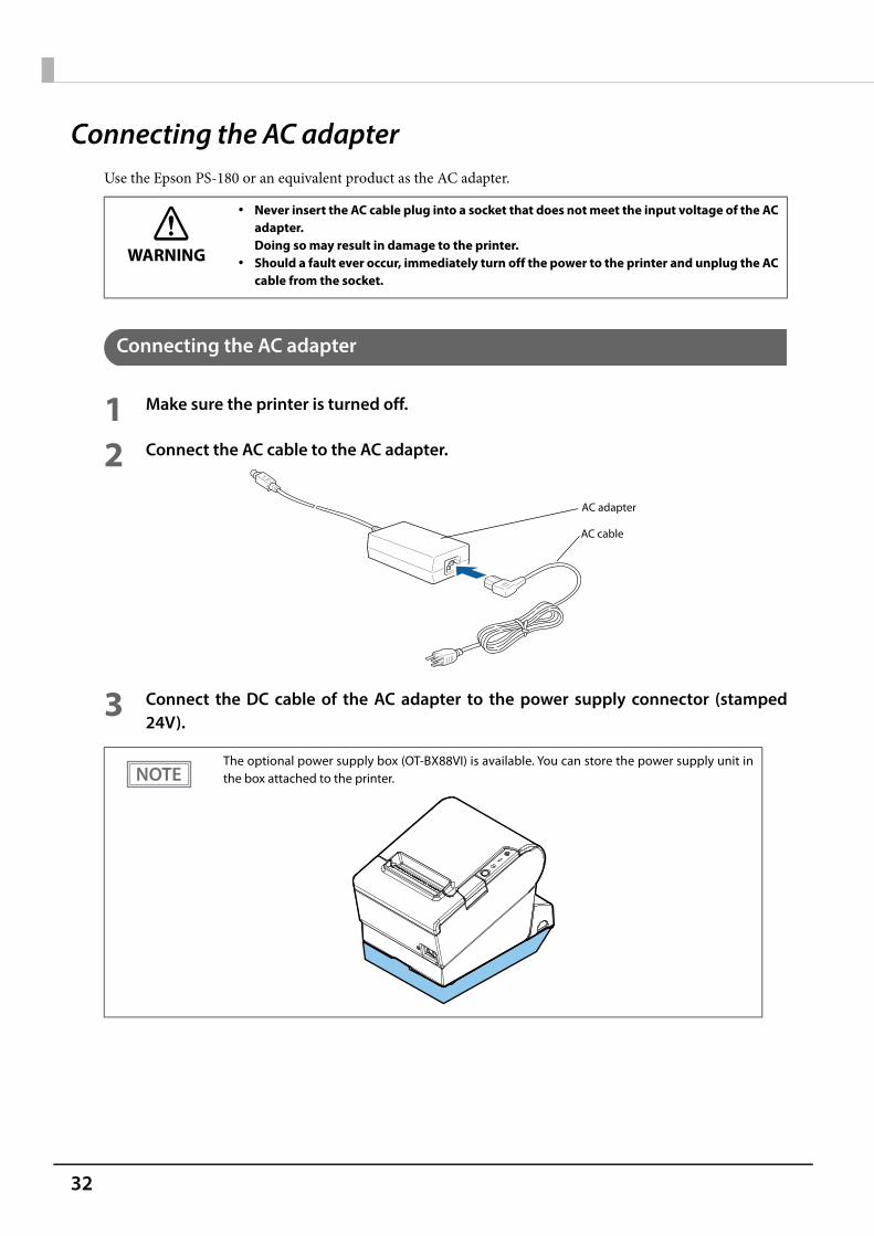
Connecting the AC adapterUse the Epson PS-180 or an equivalent product as the AC adapter.
Connecting the AC adapter
1 Make sure the printer is turned off.
2 Connect the AC cable to the AC adapter.
3 Connect the DC cable of the AC adapter to the power supply connector (stamped24V).
WARNING
Never insert the AC cable plug into a socket that does not meet the input voltage of the ACadapter.Doing so may result in damage to the printer.
Should a fault ever occur, immediately turn off the power to the printer and unplug the ACcable from the socket.
The optional power supply box (OT-BX88VI) is available. You can store the power supply unit inthe box attached to the printer.
AC adapter
AC cable
33
Chapter 2 Setup
2
Connecting the Printer to the Host
USB Interface
When using USB cable to connect with host device, connect the USB cable to the printer, and after starting thehost device, turn the printer on.
Ethernet Interface
Use ethernet cable to connect the printer to network via a hub.Use Epson TM-T88VI Utility for Windows or EpsonNet Config to set network.For details on Epson TM-T88VI Utility for Windows, refer to TM-T88VI Utility User's Manual.For details on EpsonNet Config, refer to EpsonNet Config User's Guide.
Be sure to install the driver before connecting the printer to the host computer. The printer uses modular connectors specifically designed for the cash drawer. Do not connect
these connectors to an ordinary telephone line.
Do not place any weight or stress on the cable when using. Doing so could damage the cable andconnectors.
When LAN cables are installed outdoors, make sure they are connected through devices that havesurge protection.Otherwise, the devices can be damaged by lightning.
Never attempt to connect the drawer kick cable or a standard telephone line cable to the LANconnector.
As same with Conventional models, you can use EpsonNet Config (Web version) in the same way.User name/password: epson
34
Wireless LAN Interface
You can connect using a wired cable (LAN/USB), or connect using SimpleAP mode, and setup a wireless LANusing a network configuration tool. When setting up multiple printers, you can connect using a wired cable(LAN/USB) and setup a wireless LAN using the Epson Deployment Tool.Using Epson TM Utility for iOS/Android, you can easily connect the printer to the network from an iOS orAndroid devices.
Setting up Using a SimpleAP Connection from a Windows Computer
Necessary ItemsPrepare the following items. Computer for setting: Windows 10/8/7/Vista
Computer equipped with a wireless LAN function Utility for setting: Epson TM-T88VI Utility for Windows or EpsonNet Config
When using wireless LAN, make sure you disconnect the LAN cable. If a LAN cable is connected,wireless LAN is disabled.
When you set up the access point at the same time, set the access point in advance and check thatit operates correctly.
Examine the radio wave situation in the surrounding area before use. Avoid using the same channel that is used in the neighboring shops where Wireless LAN is used. Wireless LANs with a frequency band of 2.4 GHz interfere with Bluetooth communication. When
using Bluetooth and Wi-Fi at the same time, we recommend using 5 GHz. When using the printer in environments where kitchen microwaves and other devices that may
interfere radio waves are installed, observe the following points. Keep the printer away from the devices, such as kitchen microwaves, that may cause radio wave
interference. Use channels that are away from the frequency bands that may cause radio wave interference. Place shields between the printer and the devices that may cause radio wave interference. Select either 2.4 GHz or 5 GHz, whichever is free from radio wave interference. In auto channel setting for the access point, do not select a channel in which the devices may
cause radio wave interference. In the infrastructure mode, W53 and W56 channels are not available to connect to a stealth SSID
access point.
For SimpleAP mode, see "Simple Setup for Wireless LAN" on page 26.
35
Chapter 2 Setup
2
Follow the steps below to connect the printer.
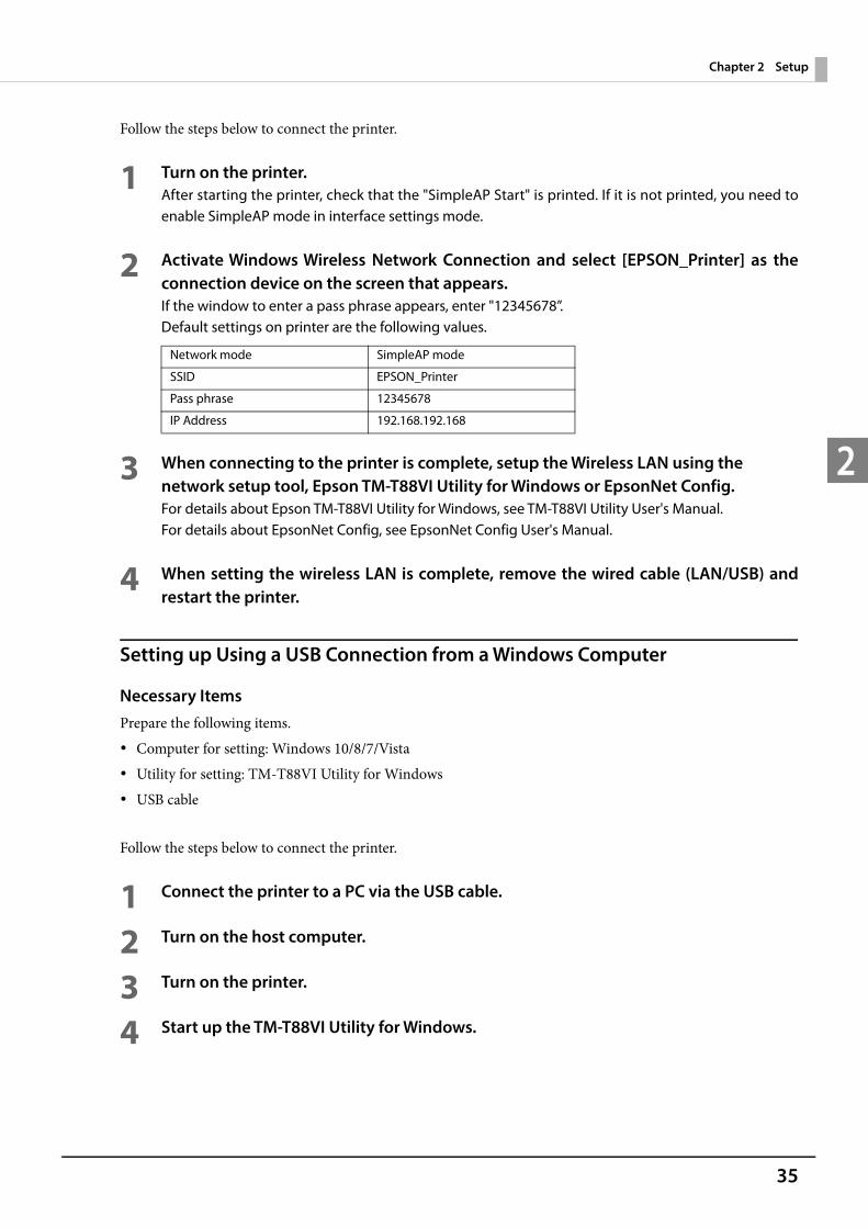
1 Turn on the printer.After starting the printer, check that the "SimpleAP Start" is printed. If it is not printed, you need toenable SimpleAP mode in interface settings mode.
2 Activate Windows Wireless Network Connection and select [EPSON_Printer] as theconnection device on the screen that appears.If the window to enter a pass phrase appears, enter "12345678”.Default settings on printer are the following values.
3 When connecting to the printer is complete, setup the Wireless LAN using the network setup tool, Epson TM-T88VI Utility for Windows or EpsonNet Config.For details about Epson TM-T88VI Utility for Windows, see TM-T88VI Utility User's Manual.For details about EpsonNet Config, see EpsonNet Config User's Manual.
4 When setting the wireless LAN is complete, remove the wired cable (LAN/USB) andrestart the printer.
Setting up Using a USB Connection from a Windows Computer
Necessary ItemsPrepare the following items. Computer for setting: Windows 10/8/7/Vista Utility for setting: TM-T88VI Utility for Windows USB cable
Follow the steps below to connect the printer.
1 Connect the printer to a PC via the USB cable.
2 Turn on the host computer.
3 Turn on the printer.
4 Start up the TM-T88VI Utility for Windows.
Network mode SimpleAP mode
SSID EPSON_Printer
Pass phrase 12345678
IP Address 192.168.192.168

36
5 Select the printer, and then press the [OK] button.If the printer is not displayed, press the "Add Port" button, and then add the printer connected byUSB.
6 Perform network I/F as well as TCP/IP settings.For details on the settings, see the TM-T88VI Utility User's Manual.
7 When you have finished making settings, disconnect the USB cable, turn off theprinter, and then turn it back on.
Setting up from a Smart Device
Necessary ItemsPrepare the following items. Device for setting: iOS or Android device Utility for setting: Epson TM Utility for iOS/Android
Running Epson TM Utility for iOS/Android
1 Run the Epson TM Utility for iOS/Android.
2 Set from “Wi-Fi Setup Wizard” in the menu.
Setup and Operation Workflow1. Select the network you want to connect to.2. Enter the passkey.3. Perform a test print.
Bluetooth Interface
Use a tool, such as a built-in Bluetooth connection tool of your device to establish the connection with theprinter. If your device is a Windows computer, use EPSON TM Bluetooth® Connector, which is a utility to easilypair a terminal and the printer. If your terminal is an iOS or Android terminal, use Epson TM Utility for iOS/Android to easily pair your terminal and the printer.
To start wireless LAN communication, be sure to disconnect the USB cable, turn off the printer,and then turn it back on.
37
Chapter 2 Setup
2
Setting up from a Windows Computer
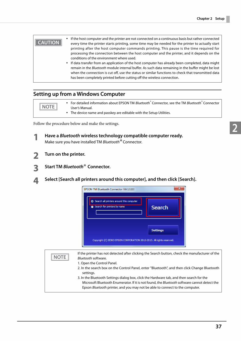
Follow the procedure below and make the settings.
1 Have a Bluetooth wireless technology compatible computer ready.Make sure you have installed TM Bluetooth® Connector.
2 Turn on the printer.
3 Start TM Bluetooth® Connector.
4 Select [Search all printers around this computer], and then click [Search].
If the host computer and the printer are not connected on a continuous basis but rather connectedevery time the printer starts printing, some time may be needed for the printer to actually startprinting after the host computer commands printing. This pause is the time required forprocessing the connection between the host computer and the printer, and it depends on theconditions of the environment where used.
If data transfer from an application of the host computer has already been completed, data mightremain in the Bluetooth module internal buffer. As such data remaining in the buffer might be lostwhen the connection is cut off, use the status or similar functions to check that transmitted datahas been completely printed before cutting off the wireless connection.
For detailed information about EPSON TM Bluetooth® Connector, see the TM Bluetooth® ConnectorUser’s Manual.
The device name and passkey are editable with the Setup Utilities.
If the printer has not detected after clicking the Search button, check the manufacturer of theBluetooth software.1. Open the Control Panel.2. In the search box on the Control Panel, enter "Bluetooth", and then click Change Bluetooth
settings.3. In the Bluetooth Settings dialog box, click the Hardware tab, and then search for the
Microsoft Bluetooth Enumerator. If it is not found, the Bluetooth software cannot detect the Epson Bluetooth printer, and you may not be able to connect to the computer.
38
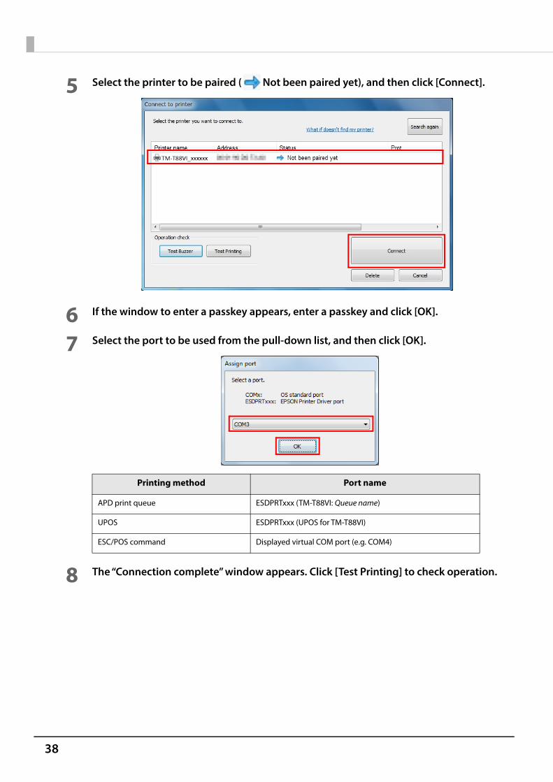
5 Select the printer to be paired ( Not been paired yet), and then click [Connect].
6 If the window to enter a passkey appears, enter a passkey and click [OK].
7 Select the port to be used from the pull-down list, and then click [OK].
8 The “Connection complete” window appears. Click [Test Printing] to check operation.
Printing method Port name
APD print queue ESDPRTxxx (TM-T88VI: Queue name)
UPOS ESDPRTxxx (UPOS for TM-T88VI)
ESC/POS command Displayed virtual COM port (e.g. COM4)
39
Chapter 2 Setup
2
9 Click [Back to Main screen] to return to the main window.
10Click the “x” button of TM Bluetooth® Connector to exit.
Setting up from a Smart Device
Necessary ItemsPrepare the following items. Device for setting: iOS or Android device Utility for setting: Epson TM Utility for iOS/Android
Running Epson TM Utility for iOS/Android
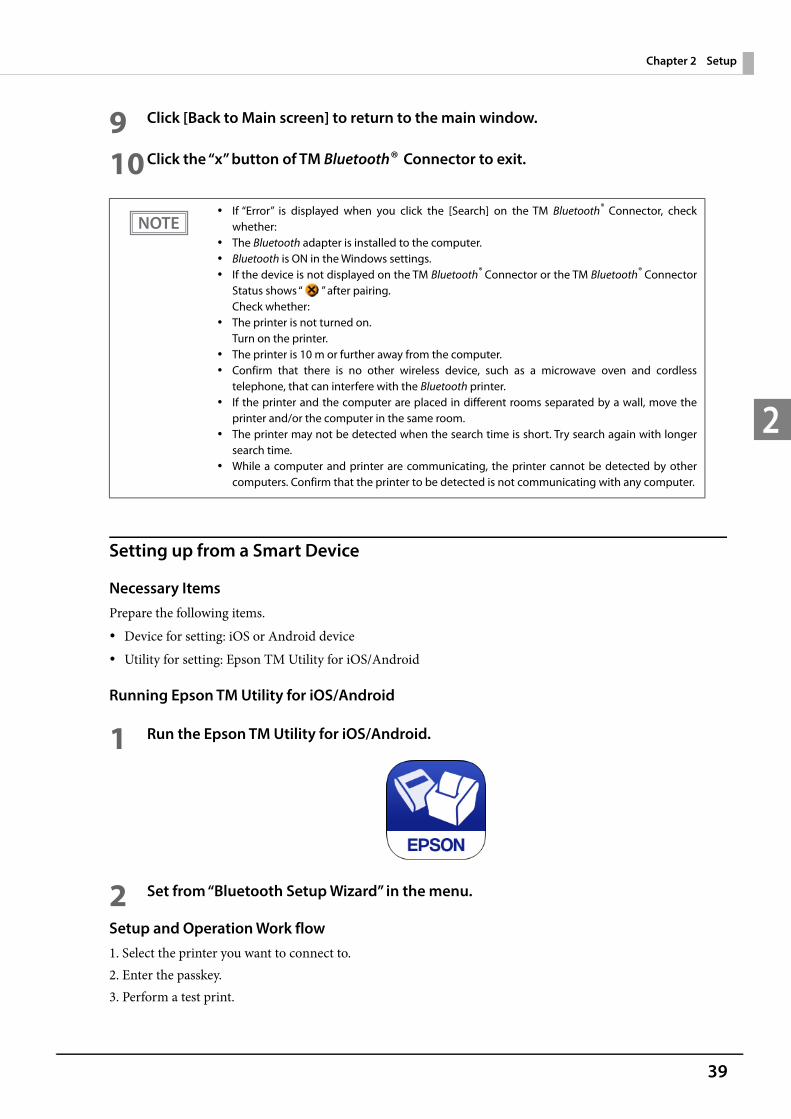
1 Run the Epson TM Utility for iOS/Android.
2 Set from “Bluetooth Setup Wizard” in the menu.
Setup and Operation Work flow1. Select the printer you want to connect to.2. Enter the passkey.3. Perform a test print.
If “Error” is displayed when you click the [Search] on the TM Bluetooth® Connector, checkwhether:
The Bluetooth adapter is installed to the computer. Bluetooth is ON in the Windows settings. If the device is not displayed on the TM Bluetooth® Connector or the TM Bluetooth® Connector
Status shows “ ” after pairing.Check whether:
The printer is not turned on.Turn on the printer.
The printer is 10 m or further away from the computer. Confirm that there is no other wireless device, such as a microwave oven and cordless
telephone, that can interfere with the Bluetooth printer. If the printer and the computer are placed in different rooms separated by a wall, move the
printer and/or the computer in the same room. The printer may not be detected when the search time is short. Try search again with longer
search time. While a computer and printer are communicating, the printer cannot be detected by other
computers. Confirm that the printer to be detected is not communicating with any computer.
40
Serial Interface
When connecting to the host computer through a serial interface (RS-232), connect a serial cable to the printer,start the host computer, and then turn on the printer.
Parallel Interface
When connecting to the host computer using a parallel interface, connect the parallel cable to the printer, startthe host computer, and then turn on the printer.
USB Plus Power Interface
When using a USB Plus Power cable to connect with the host device, connect the flat connector of the USB PlusPower cable to the printer, and the square connector to the device. After starting the host device, turn theprinter on.
When using connectors equipped with screws, tighten the screws on both sides to secure theconnectors firmly.
When using interface cables equipped with a ground line, attach the ground line to the screw holemarked "FG" on the printer.
When using interface cables equipped with a ground line, attach the ground line to the screw holemarked "FG" on the printer.
When using USB Plus Power Interface, be careful of the following points. Do not connect an AC adapter and USB (Type-B) simultaneously. Do not remove or insert the USB Plus Power cable while the printer is still on.
41
Chapter 2 Setup
2
Connecting the Cash Drawer
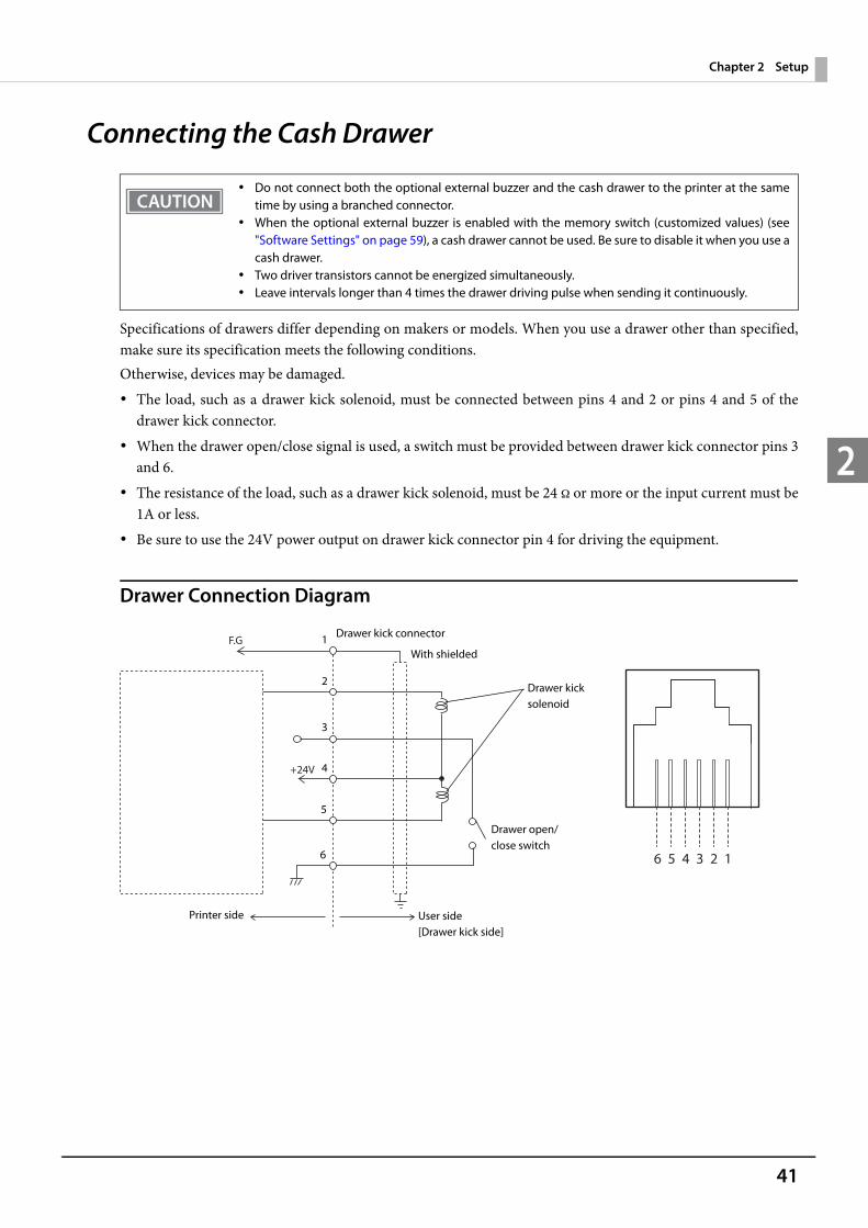
Specifications of drawers differ depending on makers or models. When you use a drawer other than specified,make sure its specification meets the following conditions.Otherwise, devices may be damaged. The load, such as a drawer kick solenoid, must be connected between pins 4 and 2 or pins 4 and 5 of the
drawer kick connector. When the drawer open/close signal is used, a switch must be provided between drawer kick connector pins 3
and 6. The resistance of the load, such as a drawer kick solenoid, must be 24 or more or the input current must be
1A or less. Be sure to use the 24V power output on drawer kick connector pin 4 for driving the equipment.
Drawer Connection Diagram
Do not connect both the optional external buzzer and the cash drawer to the printer at the sametime by using a branched connector.
When the optional external buzzer is enabled with the memory switch (customized values) (see"Software Settings" on page 59), a cash drawer cannot be used. Be sure to disable it when you use acash drawer.
Two driver transistors cannot be energized simultaneously. Leave intervals longer than 4 times the drawer driving pulse when sending it continuously.
F.G
+24V
6 5 4 3 2 1
With shielded
Drawer kick connector
Printer side User side [Drawer kick side]
Drawer open/close switch
Drawer kick solenoid
1
2
3
4
5
6
42
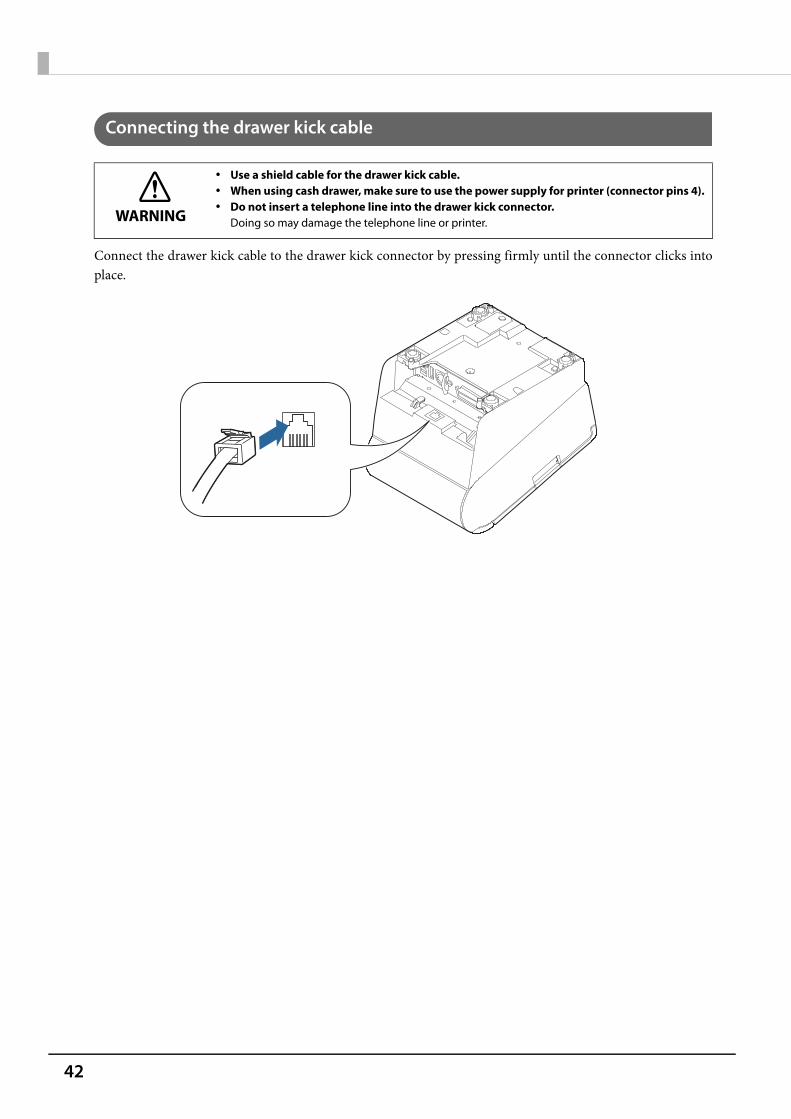
Connecting the drawer kick cable
Connect the drawer kick cable to the drawer kick connector by pressing firmly until the connector clicks intoplace.
WARNING
Use a shield cable for the drawer kick cable. When using cash drawer, make sure to use the power supply for printer (connector pins 4). Do not insert a telephone line into the drawer kick connector.
Doing so may damage the telephone line or printer.
43
Chapter 2 Setup
2
Setting the Built-in Buzzer (for Model with a Built-in Buzzer)
For specifications with a built-in buzzer, a pulse output is sent to drawer kick connector pin 5 to beep thebuzzer.When using a cash drawer, connect a cash drawer operated by pin 2.If you have to use a cash drawer operated by pin 5, change the DIP switch settings for the buzzer circuit.For details, see "Setting the DIP Switches" - "Setting Procedure" on page 53.
DIP Switch for Buzzer Circuit
DIP switch
Specified connector pin ON OFFDefault setting
1 Drawer kick connector pin 2 Buzzer beeps. Buzzer does not beep.
ON
2 Drawer kick connector pin 5 Buzzer beeps. Buzzer does not beep.
OFF
Do not set the buzzer to beep for pin numbers used for drawer operations. The buzzer and thecash drawer cannot be operated by one pulse signal.

44
Connecting the Optional External BuzzerWhen the optional external buzzer (model: OT-BZ20) is connected to the drawer kick connector of the printer, you can set the printer so that it beeps when you send commands, when an error occurs, when executed autocutting, and when detected paper end. Settings for sound patterns and frequency depending on the occasions the buzzer beeps are also available.You need to set with the memory switch (customized values) for buzzer enable/disable setting, sound patternsetting, and frequency setting. For information about the memory switch (customized values), see "SoftwareSettings" on page 59.
Attachment Position
The optional external buzzer is recommended to be installed in the following positions.
Be sure to turn off the printer before you connect/disconnect the optional external buzzer. Do not connect both the optional external buzzer and the cash drawer to the printer at the
same time by using a branched connector.
Do not install the optional external buzzer at the roll paper exit. To prevent liquid from entering inside, it is recommended to install the optional external buzzer
so that the volume adjustment knob is positioned sideways or downward.
Volume adjustment knob
45
Chapter 2 Setup
2
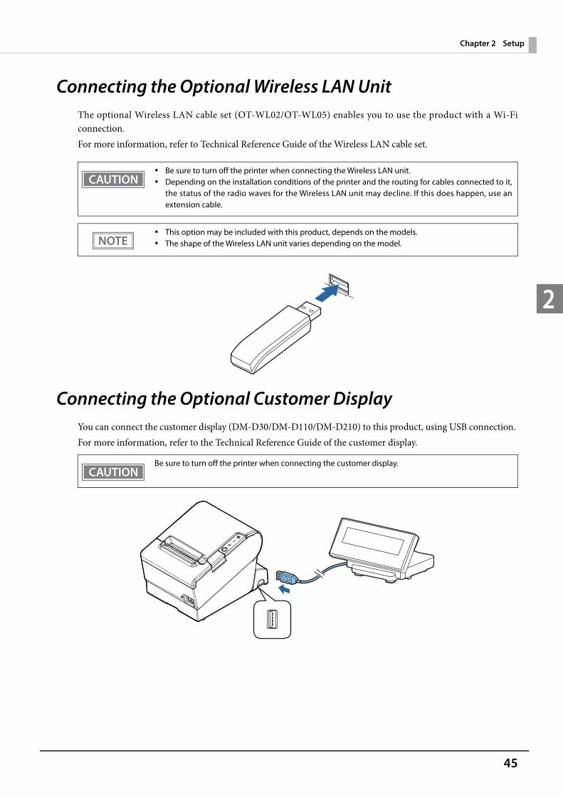
Connecting the Optional Wireless LAN UnitThe optional Wireless LAN cable set (OT-WL02/OT-WL05) enables you to use the product with a Wi-Ficonnection.For more information, refer to Technical Reference Guide of the Wireless LAN cable set.
Connecting the Optional Customer DisplayYou can connect the customer display (DM-D30/DM-D110/DM-D210) to this product, using USB connection. For more information, refer to the Technical Reference Guide of the customer display.
Be sure to turn off the printer when connecting the Wireless LAN unit. Depending on the installation conditions of the printer and the routing for cables connected to it,
the status of the radio waves for the Wireless LAN unit may decline. If this does happen, use anextension cable.
This option may be included with this product, depends on the models. The shape of the Wireless LAN unit varies depending on the model.
Be sure to turn off the printer when connecting the customer display.

46
Attaching the Connector CoverWhen using the connector cover, attach the connector cover.Follow the steps below to attach the connector cover to protect cables.
1 Turn over the printer.
2 Position the two hooks on both sides of the connector cover so that they hook theprinter case.
3 Push the connector cover down to click onto the printer case.
4 Pass each cable through the cable exits at the bottom of the connector cover.
5 Turn over the printer and make sure the cables are not pinched.
Hooks

47
Chapter 2 Setup
2
You can use the enclosed screw to fix the connector cover.
To remove the connector cover, turn the printer over, remove the screw, and push theconnector cover down while pushing both sides of the connector cover inward to detach thehooks from the printer case.

48
Arranging the CablesRoute the cables when using the connector cover.Pass the cables through cable exits in the connector cover. The connector cover has cable exits on the back andboth sides.You can also route the cables out the front by passing them through the notch in the printer bottom.
If you want to pass the USB cable through the cable exit on the back, fit the cable under the hook on the printerto prevent the cable from coming off and to prevent too much force being applied to the connector section.
You can also attach bottom cover to hide connectors.Make sure the cable does not get caught when installing.
Hooks
49
Chapter 2 Setup
2
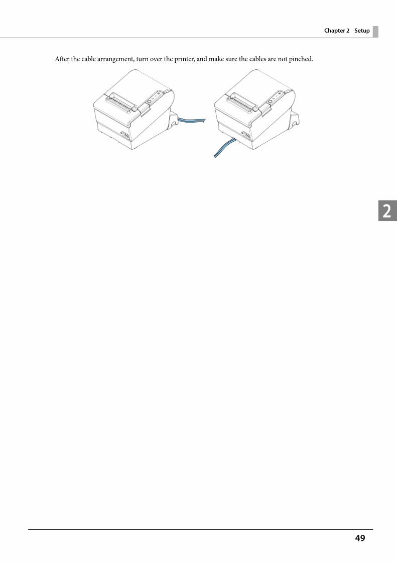
After the cable arrangement, turn over the printer, and make sure the cables are not pinched.
50
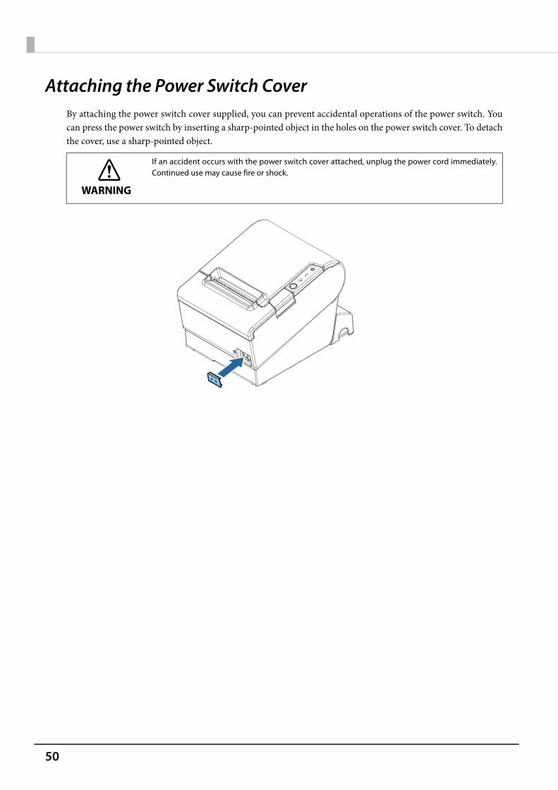
Attaching the Power Switch CoverBy attaching the power switch cover supplied, you can prevent accidental operations of the power switch. Youcan press the power switch by inserting a sharp-pointed object in the holes on the power switch cover. To detachthe cover, use a sharp-pointed object.
WARNING
If an accident occurs with the power switch cover attached, unplug the power cord immediately.Continued use may cause fire or shock.
51
Chapter 2 Setup
2
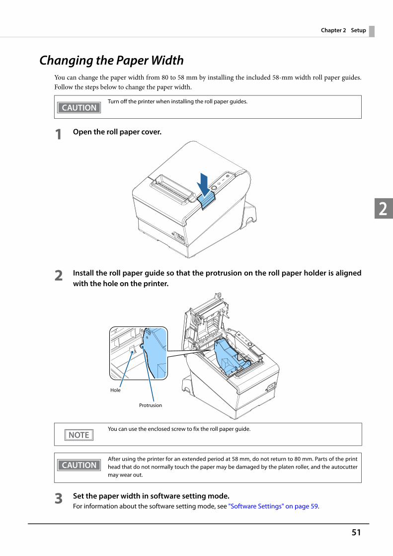
Changing the Paper WidthYou can change the paper width from 80 to 58 mm by installing the included 58-mm width roll paper guides.Follow the steps below to change the paper width.
1 Open the roll paper cover.
2 Install the roll paper guide so that the protrusion on the roll paper holder is alignedwith the hole on the printer.
3 Set the paper width in software setting mode.For information about the software setting mode, see "Software Settings" on page 59.
Turn off the printer when installing the roll paper guides.
You can use the enclosed screw to fix the roll paper guide.
After using the printer for an extended period at 58 mm, do not return to 80 mm. Parts of the printhead that do not normally touch the paper may be damaged by the platen roller, and the autocuttermay wear out.
Hole
Protrusion

52
RTC SettingsThe time for the RTC (Real Time Clock) may be initialized when starting up for the first time. If the time is initialized, make settings using the Setup Utilities.For details on making settings using the Setup Utilities, see the TM-T88VI Utility User's Manual.
53
Chapter 3 Advanced Usage
3
Advanced Usage
Setting the DIP SwitchesOn this printer, you can make various settings with DIP switches.The DIP switches are already set for the current interfaces. Change the setting if necessary.Functions of the DIP switches differ depending on the interface.
Setting Procedure
Follow the steps below to change the DIP switch settings.
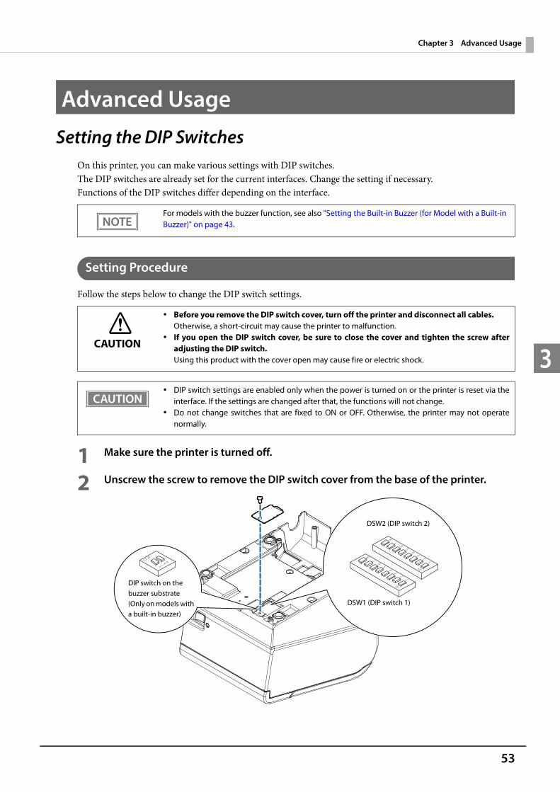
1 Make sure the printer is turned off.
2 Unscrew the screw to remove the DIP switch cover from the base of the printer.
For models with the buzzer function, see also "Setting the Built-in Buzzer (for Model with a Built-in Buzzer)" on page 43.
CAUTION
Before you remove the DIP switch cover, turn off the printer and disconnect all cables.Otherwise, a short-circuit may cause the printer to malfunction.
If you open the DIP switch cover, be sure to close the cover and tighten the screw afteradjusting the DIP switch.Using this product with the cover open may cause fire or electric shock.
DIP switch settings are enabled only when the power is turned on or the printer is reset via theinterface. If the settings are changed after that, the functions will not change.
Do not change switches that are fixed to ON or OFF. Otherwise, the printer may not operatenormally.
DSW2 (DIP switch 2)
DSW1 (DIP switch 1)
DIP switch on the buzzer substrate(Only on models with a built-in buzzer)

54
3 Set the DIP switches, using the tip of a tool, such as a small screwdriver.
4 Replace the DIP switch cover, and screw it in place.

55
Chapter 3 Advanced Usage
3
When a Serial Interface is Connected
DIP Switch Bank 1
Transmission Speed (DIP Switches 1-7/1-8)
bps: bits per second* The default value of transmission speed set with software settings is 38400 bps. (See "Software Settings" on
page 59.)
SW Function ON OFFDefaultsetting
1-1 Data reception error Ignored Prints “?” OFF
1-2 Receive buffer capacity 45 bytes 4 KB OFF
1-3 Handshaking XON/XOFF DTR/DSR OFF
1-4 Word length 7 bits 8 bits OFF
1-5 Parity check Yes No OFF
1-6 Parity selection Even Odd OFF
1-7Baud rate selections
See the " Transmission Speed (DIP Switches 1-7/1-8)" table below.
ON
1-8 OFF
For DIP switch 1-2 (Receive buffer capacity), see also DIP switch 2-5 (Sets the release condition ofthe receive buffer BUSY state.)
Transmission speed (bps: bits per second) SW 1-7 SW 1-8Depends on the software setting mode settings.* ON ON
4800 OFF ON
9600 (default) ON OFF
19200 OFF OFF
Depending on print conditions, such as print duty, print head temperature, and data transmissionspeed, print speed is automatically adjusted, which can cause white lines due to intermittentprint (the motor sometimes stops). To avoid this, set the transmission speed higher or keep theprint speed constant by setting it lower.
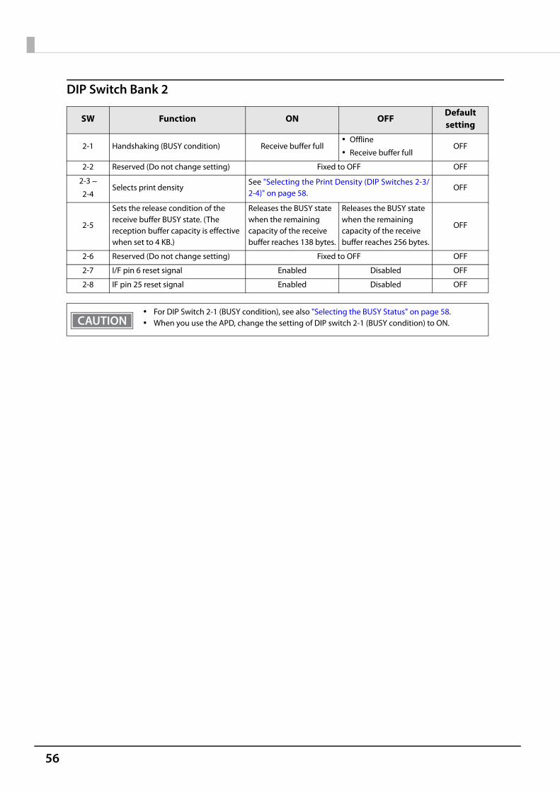
56
DIP Switch Bank 2
SW Function ON OFFDefaultsetting
2-1 Handshaking (BUSY condition) Receive buffer full Offline
Receive buffer fullOFF
2-2 Reserved (Do not change setting) Fixed to OFF OFF
2-3
2-4Selects print density
See "Selecting the Print Density (DIP Switches 2-3/2-4)" on page 58.
OFF
2-5
Sets the release condition of the receive buffer BUSY state. (The reception buffer capacity is effective when set to 4 KB.)
Releases the BUSY state when the remaining capacity of the receive buffer reaches 138 bytes.
Releases the BUSY state when the remaining capacity of the receive buffer reaches 256 bytes.
OFF
2-6 Reserved (Do not change setting) Fixed to OFF OFF
2-7 I/F pin 6 reset signal Enabled Disabled OFF
2-8 IF pin 25 reset signal Enabled Disabled OFF
For DIP Switch 2-1 (BUSY condition), see also "Selecting the BUSY Status" on page 58. When you use the APD, change the setting of DIP switch 2-1 (BUSY condition) to ON.
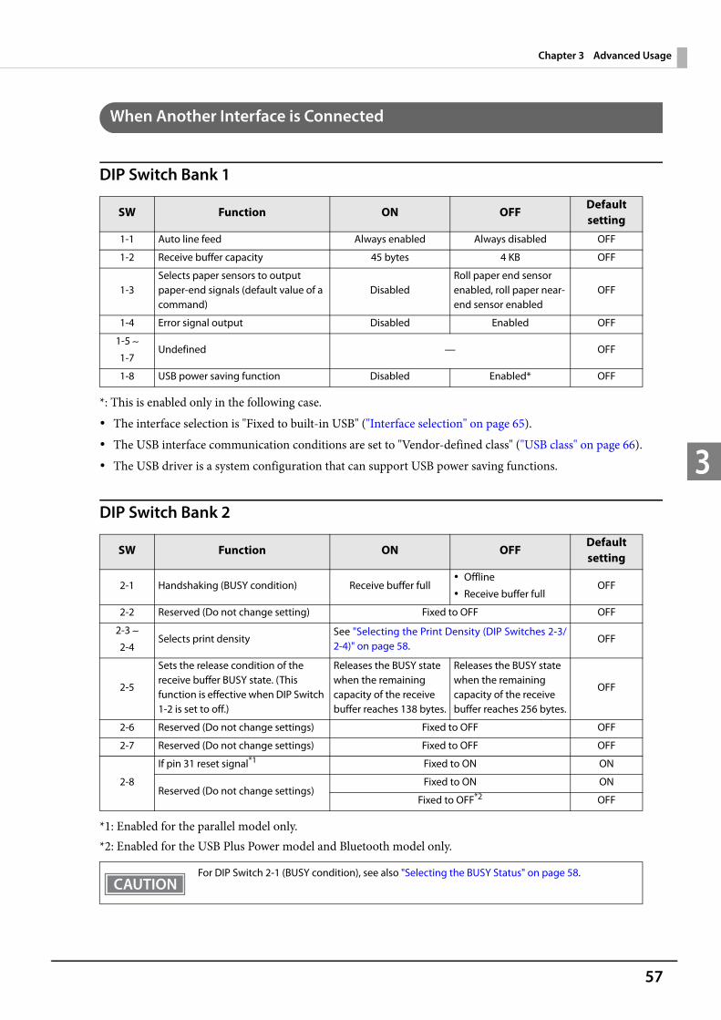
57
Chapter 3 Advanced Usage
3
When Another Interface is Connected
DIP Switch Bank 1
*: This is enabled only in the following case. The interface selection is "Fixed to built-in USB" ("Interface selection" on page 65). The USB interface communication conditions are set to "Vendor-defined class" ("USB class" on page 66). The USB driver is a system configuration that can support USB power saving functions.
DIP Switch Bank 2
*1: Enabled for the parallel model only. *2: Enabled for the USB Plus Power model and Bluetooth model only.
SW Function ON OFFDefaultsetting
1-1 Auto line feed Always enabled Always disabled OFF
1-2 Receive buffer capacity 45 bytes 4 KB OFF
1-3Selects paper sensors to output paper-end signals (default value of a command)
DisabledRoll paper end sensor enabled, roll paper near-end sensor enabled
OFF
1-4 Error signal output Disabled Enabled OFF
1-5
1-7Undefined — OFF
1-8 USB power saving function Disabled Enabled* OFF
SW Function ON OFFDefaultsetting
2-1 Handshaking (BUSY condition) Receive buffer full Offline
Receive buffer fullOFF
2-2 Reserved (Do not change setting) Fixed to OFF OFF
2-3
2-4Selects print density
See "Selecting the Print Density (DIP Switches 2-3/2-4)" on page 58.
OFF
2-5
Sets the release condition of the receive buffer BUSY state. (This function is effective when DIP Switch 1-2 is set to off.)
Releases the BUSY state when the remaining capacity of the receive buffer reaches 138 bytes.
Releases the BUSY state when the remaining capacity of the receive buffer reaches 256 bytes.
OFF
2-6 Reserved (Do not change settings) Fixed to OFF OFF
2-7 Reserved (Do not change settings) Fixed to OFF OFF
2-8
If pin 31 reset signal*1 Fixed to ON ON
Reserved (Do not change settings)Fixed to ON ON
Fixed to OFF*2 OFF
For DIP Switch 2-1 (BUSY condition), see also "Selecting the BUSY Status" on page 58.
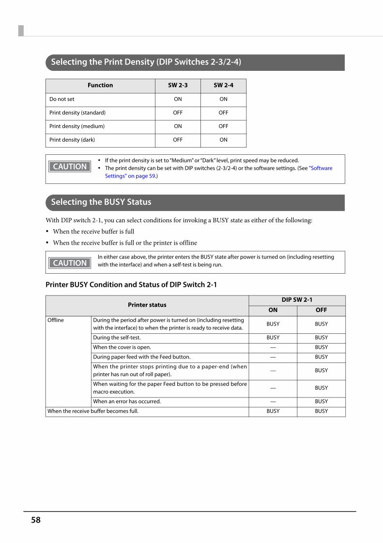
58
Selecting the Print Density (DIP Switches 2-3/2-4)
Selecting the BUSY Status
With DIP switch 2-1, you can select conditions for invoking a BUSY state as either of the following: When the receive buffer is full When the receive buffer is full or the printer is offline
Printer BUSY Condition and Status of DIP Switch 2-1
Function SW 2-3 SW 2-4
Do not set ON ON
Print density (standard) OFF OFF
Print density (medium) ON OFF
Print density (dark) OFF ON
If the print density is set to “Medium” or “Dark” level, print speed may be reduced. The print density can be set with DIP switches (2-3/2-4) or the software settings. (See "Software
Settings" on page 59.)
In either case above, the printer enters the BUSY state after power is turned on (including resetting with the interface) and when a self-test is being run.
Printer statusDIP SW 2-1
ON OFFOffline During the period after power is turned on (including resetting
with the interface) to when the printer is ready to receive data.BUSY BUSY
During the self-test. BUSY BUSY
When the cover is open. — BUSY
During paper feed with the Feed button. — BUSY
When the printer stops printing due to a paper-end (whenprinter has run out of roll paper).
— BUSY
When waiting for the paper Feed button to be pressed beforemacro execution.
— BUSY
When an error has occurred. — BUSY
When the receive buffer becomes full. BUSY BUSY

59
Chapter 3 Advanced Usage
3
Software SettingsWith the memory switches and customized values, which are software settings for this printer, you can set thevarious functions.For an outline of the functions, see the following section. Use the Epson TM-T88VI Utility for Windows, EpsonTM Utility for iOS/Android, or Software Setting Mode to set the memory switches.
The software setting mode is the mode set using the printer's panel. For details on panel operations, see "Software Setting Mode" on page 72.
Item\MethodSoftware Setting Mode
Epson TM-T88VI Utility for Windows
Epson TM Utility for
iOS/Android
Mem
ory
Swit
ches Automatic line feed ✔ ✔ ✔
USB power saving function ✔ ✔ ✔
Paper sensors to output paper end signal ✔ ✔ ✔
Error signal output✔ ✔ ✔
Cust
omiz
ed V
alue
s
Automatic paper reduction ✔ ✔ ✔
Auto paper feed&cut at cover close ✔ ✔ ✔
Buzzer function ✔ ✔
Command execution during offline ✔ ✔ ✔
Character code table defaults ✔ ✔
International character defaults ✔ ✔
Font A auto replacement ✔
Font B auto replacement ✔
Print density ✔ ✔ ✔
Print speed ✔ ✔ ✔
Column emulation mode ✔ ✔ ✔
Print density during multi-tone printing ✔ ✔ ✔
Power supply output ✔ ✔ ✔
Paper width ✔ ✔ ✔
Interface selection ✔ ✔ ✔
Interface switch wait time ✔ ✔ ✔
Main interface selection ✔ ✔ ✔
Startup display ✔ ✔ ✔
Auto re-connect iOS ✔ ✔ ✔
Baud rate ✔ ✔
USB class ✔ ✔ ✔

60
1: The setting item may not be available depending on the area.2: Enabled only under the following conditions.
Epson TM Utility for iOS/Android Ver.3.6.0 or laterFirmware Ver.40.10 ESC/POS or laterTM-T88VI Utility for Windows Ver.1.30 or later
USB IEEE1284 device ID ✔
Reset Bluetooth Settings ✔
Restore & Delete Defined Data ✔
Print Data Parsing setting*1 ✔ ✔ ✔
Cut Error Release Method ✔ ✔
Logo ✔ ✔
ePOS-Print ✔ ✔
ProxyInfo ✔ ✔
Server Direct Print ✔ ✔
Status Notification ✔ ✔
Print Forwarding ✔ ✔
Web Contents Updater ✔ ✔
PHP ✔ ✔
Document Path ✔ ✔
Customer Display ✔ ✔
Network CS Authentication ✔ ✔
Network Dev Info ✔ ✔
Ethernet Config ✔ ✔
Wi-Fi Config ✔ ✔
SSL/TLS Config ✔
Certificate Config ✔
TCP/IP Config ✔ ✔
SNMP Config ✔ ✔
Time Config ✔ ✔
LPR Config ✔ ✔
Port9100 Config ✔ ✔
IP/Port Filter Config ✔ ✔
Bluetooth communication interval during power saving mode*2
✔ ✔ ✔
Item\MethodSoftware Setting Mode
Epson TM-T88VI Utility for Windows
Epson TM Utility for
iOS/Android

61
Chapter 3 Advanced Usage
3
Functions
Automatic line feed Normally disabled (default setting) Normally enabled
USB power saving function Disabled Enabled (default setting)
Paper sensors to output paper end signal Roll paper out detector (default settings) Disabled
Error signal output Enabled (default setting) Disabled
Automatic paper reduction
Extra upper space reduction Disabled (default setting) Enabled
This is only enabled when using a serial interface. When using another interface, make settings byusing the DIP switches.
Enabled when anything except for UB-U06/UB-R04/UB-IU01 is installed to the UIB.
The USB power-saving function is valid only when the USB interface communication condition is set to the vendor-defined class and the system configuration is set so that the USB driver can support the USB power-saving function.
When using a parallel interface, make settings by using the DIP switches.
When using a parallel interface, make settings by using the DIP switches.
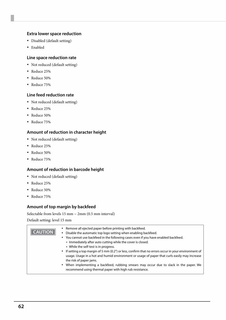
62
Extra lower space reduction Disabled (default setting) Enabled
Line space reduction rate Not reduced (default setting) Reduce 25% Reduce 50% Reduce 75%
Line feed reduction rate Not reduced (default setting) Reduce 25% Reduce 50% Reduce 75%
Amount of reduction in character height Not reduced (default setting) Reduce 25% Reduce 50% Reduce 75%
Amount of reduction in barcode height Not reduced (default setting) Reduce 25% Reduce 50% Reduce 75%
Amount of top margin by backfeedSelectable from levels 15 mm ~ 2mm (0.5 mm interval)Default setting: level 15 mm
Remove all ejected paper before printing with backfeed. Disable the automatic top logo setting when enabling backfeed. You cannot use backfeed in the following cases even if you have enabled backfeed.
Immediately after auto cutting while the cover is closed. While the self-test is in progress.
If setting a top margin of 5 mm {0.2"} or less, confirm that no errors occur in your environment ofusage. Usage in a hot and humid environment or usage of paper that curls easily may increasethe risk of paper jams.
When implementing a backfeed, rubbing smears may occur due to slack in the paper. Werecommend using thermal paper with high rub resistance.

63
Chapter 3 Advanced Usage
3
Auto paper feed&cut at cover close Cuts Does not cut (default setting)
Buzzer function
Enables/disables Disabled (default setting) Enabled
Buzzer frequency (Error) Does not sound Sounds 1 time Sounds continuously (default setting)
Sound pattern (Autocut)Selectable from Patterns A to EDefault setting: Pattern A
Buzzer frequency (Autocut) Does not sound Sounds 1 time (default setting)
Sound pattern (Pulse 1)Selectable from Patterns A to EDefault setting: Pattern A
Buzzer frequency (Pulse 1) Does not sound Sounds 1 time (default setting)
Sound pattern (Pulse 2)Selectable from Patterns A to EDefault setting: Pattern B
Buzzer frequency (Pulse 2) Does not sound Sounds 1 time (default setting)
For information about how to connect the optional external buzzer, see "Connecting theOptional External Buzzer" on page 44.
When the optional external buzzer is enabled, a cash drawer cannot be used. Be sure to disableit when you use a cash drawer.
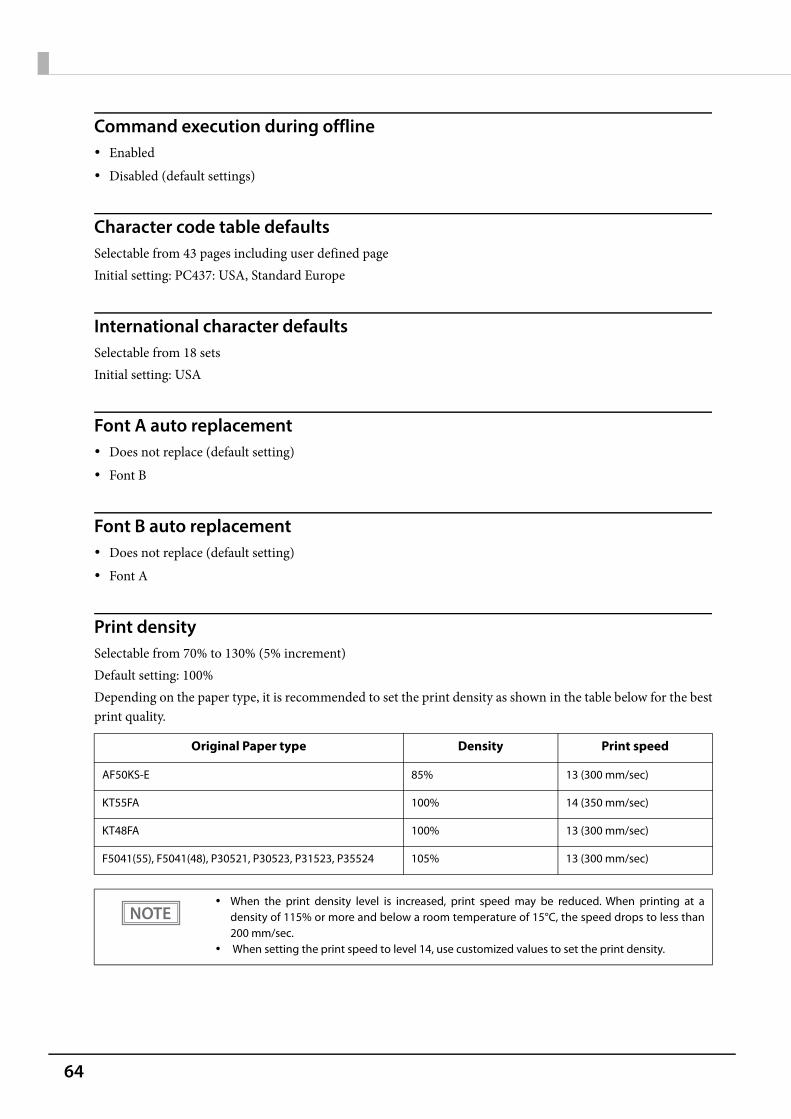
64
Command execution during offline Enabled Disabled (default settings)
Character code table defaultsSelectable from 43 pages including user defined pageInitial setting: PC437: USA, Standard Europe
International character defaultsSelectable from 18 sets Initial setting: USA
Font A auto replacement Does not replace (default setting) Font B
Font B auto replacement Does not replace (default setting) Font A
Print densitySelectable from 70% to 130% (5% increment)Default setting: 100%Depending on the paper type, it is recommended to set the print density as shown in the table below for the bestprint quality.
Original Paper type Density Print speed
AF50KS-E 85% 13 (300 mm/sec)
KT55FA 100% 14 (350 mm/sec)
KT48FA 100% 13 (300 mm/sec)
F5041(55), F5041(48), P30521, P30523, P31523, P35524 105% 13 (300 mm/sec)
When the print density level is increased, print speed may be reduced. When printing at adensity of 115% or more and below a room temperature of 15°C, the speed drops to less than200 mm/sec.
When setting the print speed to level 14, use customized values to set the print density.

65
Chapter 3 Advanced Usage
3
Print speedSelectable from levels 1 to 14 (Slow ~ Fast)Default setting: level 13
Column emulation mode Standard mode (default setting) 48 column mode
Print density during multi-tone printingSelectable from 70% to 130% (5% increment)Default setting: 100%
Power supply outputSelectable from levels 1 to 3 low power loadDefault setting: level 3
Paper width 80mm (default setting) 58mm
Interface selection Fixed to UIB Fixed to built-in USB Fixed to Ethernet (Wi-Fi) UIB/Bluetooth Built-in USB auto switch The entire interface is enabled (default setting)
Print speed is restricted by the settings for the number of head electrification divisions. The maximum printing speed of 350 mm/s is only possible when 1 electrification division is selected.
The maximum printing speed when using 58 mm is 300 mm/s.
Depending on print conditions, such as print duty, print head temperature, and data transmission speed, print speed is automatically adjusted, which may cause white lines due to intermittent print (the motor sometimes stops). To avoid this, keep the print speed constant by setting it lower.
This function is supported only on the ANK model.
66
Interface switch wait timeSelect from 1 to 10 seconds (in intervals of 1 second)1 second (default setting)
Main interface selection Auto (interface that receives data first) (default setting) UIB USB UIB/Bluetooth Ethernet/Wi-Fi No main connection I/F
Startup display Enabled Disabled (default setting)
Auto re-connect iOS Enabled (default settings) Disabled
Baud rate 2400 bps 4800 bps 9600 bps 19200 bps 38400 bps (default setting) 57600 bps 115200 bps
USB class Printer class (default setting) Vendor-defined class
When using this printer with multiple interfaces, make sure the interface that is always connected to be set as the main connection.
When using multiple interfaces, set the receive buffer capacity to 4 KB. You cannot use wired LAN and wireless LAN at the same time.
The displayed items vary depending on the interface configuration. For information about the function, see "Printing Using Multiple Interfaces" on page 28.
67
Chapter 3 Advanced Usage
3
USB IEEE1284 device ID Do not output IEEE1284 Device ID Output IEEE1284 Device ID (default setting)
Print Data Parsing setting Disable (default) Enable
Bluetooth communication interval during power saving mode Level 1 (Standard) (Initial setting) Level 2 (Short)
The setting item may not be available depending on the region.
By changing the setting to "Level 2 (Short)," you can shorten the time until printing begins or the time until information is shown on the customer display connected to the printer.However, because the communication frequency increases, the power consumption of the printer and the host also increases.Also, depending on the host, this setting may not be enabled, and the host-specified communication interval may be used.
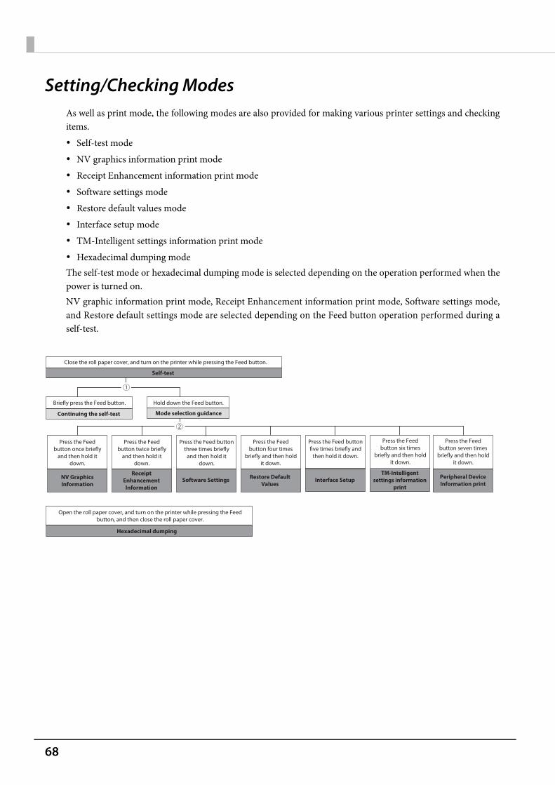
68
Setting/Checking ModesAs well as print mode, the following modes are also provided for making various printer settings and checkingitems. Self-test mode NV graphics information print mode Receipt Enhancement information print mode Software settings mode Restore default values mode Interface setup mode TM-Intelligent settings information print mode Hexadecimal dumping modeThe self-test mode or hexadecimal dumping mode is selected depending on the operation performed when thepower is turned on.NV graphic information print mode, Receipt Enhancement information print mode, Software settings mode,and Restore default settings mode are selected depending on the Feed button operation performed during aself-test.
Close the roll paper cover, and turn on the printer while pressing the Feed button.
Self-test
Briefly press the Feed button. Hold down the Feed button.
Press the Feed button once briefly
and then hold it down.
Open the roll paper cover, and turn on the printer while pressing the Feed button, and then close the roll paper cover.
Continuing the self-test Mode selection guidance
NV Graphics Information
Hexadecimal dumping
Press the Feed button twice briefly
and then hold it down.
Receipt Enhancement Information
Press the Feed button three times briefly
and then hold it down.
Software Settings
Press the Feed button four times
briefly and then hold it down.
Restore Default Values
Press the Feed button five times briefly and
then hold it down.
Interface Setup
Press the Feed button six times
briefly and then hold it down.
TM-Intelligent settings information
Press the Feed button seven times
briefly and then hold it down.
Peripheral Device Information print
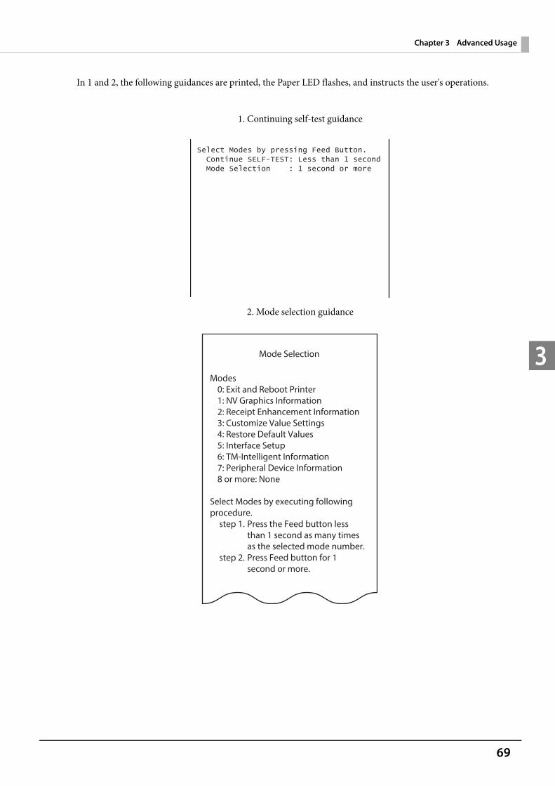
69
Chapter 3 Advanced Usage
3
In 1 and 2, the following guidances are printed, the Paper LED flashes, and instructs the user's operations.
1. Continuing self-test guidance
2. Mode selection guidance
Mode Selection
Modes0: Exit and Reboot Printer1: NV Graphics Information2: Receipt Enhancement Information3: Customize Value Settings4: Restore Default Values5: Interface Setup6: TM-Intelligent Information7: Peripheral Device Information8 or more: None
Select Modes by executing following procedure.
step 1. Press the Feed button less than 1 second as many times as the selected mode number.
step 2. Press Feed button for 1 second or more.

70
Self-test Mode
You can check the following items using the self-test. Product name Firmware version Product serial number Interface type Resident fonts Maintenance counter information (head running length, number of times of autocutting) Setting condition of the DIP switch
Follow the steps below.
1 Close the roll paper cover.
2 While pressing the Feed button, turn on the printer. (Hold down the Feed buttonuntil printing starts.)After printing the current print status, a Continuing self-test guidance is printed, and the Power LEDflashes.
3 Briefly press the Feed button (less than one second) to continue the self-test.The printer prints a rolling pattern on the roll paper, using the built-in character set.After “*** completed ***” is printed, the printer initializes and switches to standard mode.
NV Graphics Information Print Mode
Prints the following NV graphic information registered to the printer. Capacity of the NV graphics Used capacity of the NV graphics Unused capacity of the NV graphics Number of NV graphics that are registered Key code, number of dots in X direction, number of dots in Y direction to be defined. NV graphics data
For details on NV graphics, see "NV Graphics Memory" on page 24.
71
Chapter 3 Advanced Usage
3
Follow the steps below.
1 After running a self-test, hold down the Feed button for at least one second, and thenselect the Mode selection.The Mode selection guidance is printed, and the Paper LED flashes.
2 After briefly (less than one second) pressing the Feed button once, hold it down for atleast one second, to print the NV graphics information.After information printing, the Mode selection guidance is printed again.
3 To finish, turn off the power, or select “Exit and Reboot Printer”.
Receipt Enhancement Information Print Mode
You can check the following items using the R/E information mode: Automatic top logo setting Automatic bottom logo setting Extended settings for automatic top/bottom logo
Follow the steps below.
1 After running a self-test, hold down the Feed button for at least one second, and thenselect the Mode selection.The Mode selection guidance is printed, and the Power LED flashes.
2 After briefly (less than one second) pressing the Feed button twice, hold it down forat least one second, to print the R/E information.After information printing, the Mode selection guidance is printed again.
3 To finish, turn off the power, or select "Exit and Reboot Printer".

72
Software Setting Mode
Set the printer's memory switches and customized values. Print density Auto reduction of amount of paper to use Enabling/disabling paper autocutting at cover close Paper width setting Auto replacement of font Print speed Command execution (offline) Specification for the top margin by backfeed Optional external buzzer control Interface setting Communication conditions using a serial interface Communication conditions using a USB interface Interface switch wait time Main interface selection
Enabling/disabling Display when interface is activating Power supply capacity Automatic line feed Select paper sensor(s) to output paper-end signals ERROR signal when an error occurs
Follow the steps below.
1 After running a self-test, hold down the Feed button for at least one second to enter the Mode selection.The Mode selection guidance is printed, and the Paper LED flashes.
2 Briefly press the Feed button three times (less than one second), hold it down for at least one second to enter the Software settings mode (Customized value setting).The Software setting mode guidance is printed, and the Paper LED flashes.
For details on the memory switches and customized values, see "Software Settings" on page 59.

73
Chapter 3 Advanced Usage
3
3 After briefly pressing the Feed button (less than one second) for the number of timesshown in the print result, hold down the button for more than one second to selectthe setting items.The setting selected as the setting item, the current settings and default settings are printed.Depending on the setting item, you may need to continue selecting the setting item before the settings are printed.For details on setting items, see "Software Settings" on page 59.
4 Select a setting by briefly pressing the Feed button (less than one second) for thenumber of times applicable to the setting, and then hold down the button for morethan one second to confirm your selection.After saving the settings, the Software setting mode guidance is printed, and the Paper LED flashes.
5 To close Software setting mode, turn off the printer, or select “Exit” to return to Modeselection guidance, and then select “Exit and Reboot Printer”.
When set to a value other than those in the software setting mode, the current settings are notprinted.
To select 0 as the item number, hold down the Feed button until printing starts. If the button is pressed a number of times that is not displayed by the Setup guidance, the
operation is invalid and the same guidance is printed.
Customize Value Settings
Modes0: Exit1: Print Current Settings2: Print Density3: Print Speed4: Automatic Paper Reduction5: Auto Paper Feed&Cut at cover close6: Paper Width7: Top Margin8: Character/Font Settings9: Interface Selection10: Interface Settings11: Command Execution (Offline)12: Power Supply Output13: Other Settings
Select Modes by executing following procedure.
step 1. Press the Feed button less than 1 second as many times as the selected mode number.
step 2. Press Feed button for 1 second or more.
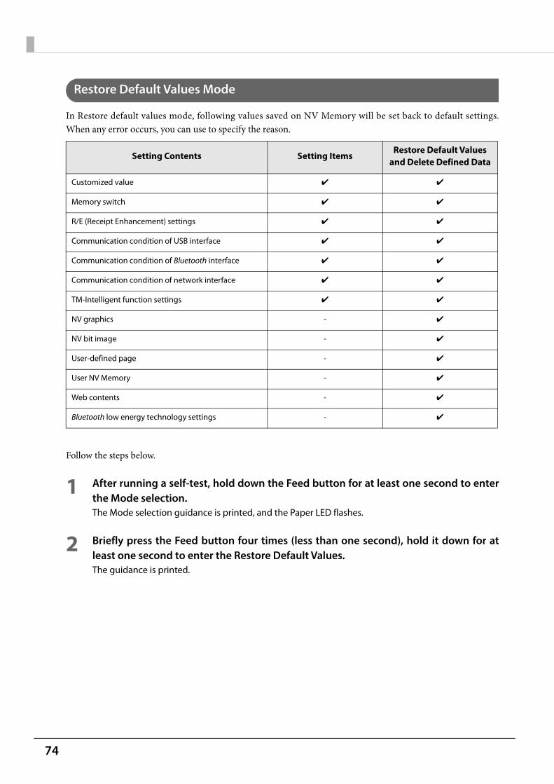
74
Restore Default Values Mode
In Restore default values mode, following values saved on NV Memory will be set back to default settings.When any error occurs, you can use to specify the reason.
Follow the steps below.
1 After running a self-test, hold down the Feed button for at least one second to enterthe Mode selection.The Mode selection guidance is printed, and the Paper LED flashes.
2 Briefly press the Feed button four times (less than one second), hold it down for atleast one second to enter the Restore Default Values.The guidance is printed.
Setting Contents Setting ItemsRestore Default Values
and Delete Defined Data
Customized value ✔ ✔
Memory switch ✔ ✔
R/E (Receipt Enhancement) settings ✔ ✔
Communication condition of USB interface ✔ ✔
Communication condition of Bluetooth interface ✔ ✔
Communication condition of network interface ✔ ✔
TM-Intelligent function settings ✔ ✔
NV graphics - ✔
NV bit image - ✔
User-defined page - ✔
User NV Memory - ✔
Web contents - ✔
Bluetooth low energy technology settings - ✔

75
Chapter 3 Advanced Usage
3
3 When only restoring the default settings:Briefly press the Feed button once (less than one second), hold it down for at leastone second. (Hold down the Feed button until the message of restore completion isprinted.)
When restoring default settings and deleting user defined data:Briefly press the Feed button twice (less than one second), and then hold it down forat least one second. (Hold down the Feed button until the restoration completemessage is printed.)
4 To finish, turn off the power.
76
Interface Setup Mode
Use this mode to setup the interface and other settings.
Follow the steps below.
1 After running a self-test, hold down the Feed button for at least one second to enterthe Mode selection.The Mode selection guidance is printed, and the Paper LED flashes.
2 Briefly press the Feed button five times (less than one second), hold it down for atleast one second to enter the Interface Setup mode.The guidance is printed.
3 After briefly pressing the Feed button (less than one second) for the number of timesshown in the print result, hold down the button for more than one second to selectthe setting items.
InitializeSelect [Wi-Fi & Ethernet Setup] or [Bluetooth Setup] and select [Initialize] to initialize the network setting parameter. The printer is reset and restarted.
SimpleAP mode (Wi-Fi model) In Wi-Fi model, select [Wi-Fi & Ethernet Setup] and select [SimpleAP] to start in SimpleAP mode (the same as the factory default setting). The printer is reset and restarted, and it begins printing the "SimpleAP Start" information.Select this to use Quick connection for Wi-Fi model.
Auto re-connect to iOS device (Bluetooth model)In Bluetooth model, select [Bluetooth Setup] and then select [Auto Re-Connect iOS], you can select whether toenable or disable auto reconnection to iOS devices.
For information on the Quick connection function, see "Simple Setup for Wireless LAN" on page 26.
For details on the auto re-connect function, see "Auto Reconnect Feature" on page 126. You can change the settings with Setup Utilities.
77
Chapter 3 Advanced Usage
3
Bluetooth Security Settings (Bluetooth model)For Bluetooth models, select [Bluetooth Setup], and then select [Security], and you can change the Bluetoothsecurity settings.
Pairing method when the security is set to Middle/High (from the printer)When the security is set to Middle/High and the printer is ready to be paired, perform the following procedure.
1 Load paper in the printer, and then turn it on.
2 Open the roll paper cover, hold down the Feed button for at least one second, andthen close the roll paper cover.
3 A status sheet is printed, and the power LED flashes a pattern indicating that pairingis now possible.
Pairing method when the security is set to High (from the host)When the security is set to High and the printer is ready to be paired, perform the following procedure.
1 Search for the printer on the Bluetooth settings screen on the host device.
2 Select the printer you want to pair with.The printer prints the Passkey.
When the security settings are changed, the link key (pairing information) is removed. If the printer isalready paired with a terminal, unpair them and then pair again.
You can change the settings with Setup Utilities.
Security Pairing Mode Pairing Method
Low Pairing is always possible Just Works
Middle Pairing is possible for one minute after printing the status sheet Just Works
High Pairing is possible for one minute after printing the status sheet Numeric Comparison/Passkey Entry
Make sure no errors have occurred and that the printer is not off-line. You cannot pair the printer while the network is starting up immediately after the power is turned
on.
Pairing is possible for one minute after printing the status sheet. You can enable pairing also by printing the status sheet by pressing the status sheet button.
78
3 Check that the printed Passkey and the Passkey displayed on the host device match,and then select "Pairing" on the host device.
TM-Intelligent Settings Information Print Mode
This function allows you to print TM-Intelligent setting information currently registered in the printer.
Follow the steps below.
1 After running a self-test, hold down the Feed button for at least one second to enterthe Mode selection.The Mode selection guidance is printed, and the Paper LED flashes.
2 Briefly press the Feed button six times (less than one second), hold it down for atleast one second to print the TM-Intelligent setting information.After information printing, the Mode selection guidance is printed again.
3 To finish, turn off the power, or select “Exit and Reboot Printer”.
Peripheral Device Information Print Mode
This function allows you to print information for the device currently connected to the printer.Customer display informationWi-Fi adapter informationBluetooth adapter information
Follow the steps below.
1 After running a self-test, hold down the Feed button for at least one second to enterthe Mode selection.The Mode selection guidance is printed, and the Paper LED flashes.
2 Briefly press the Feed button seven times (less than one second), hold it down for atleast one second to print the Peripheral Device Information.After information printing, the Mode selection guidance is printed again.
3 To finish, turn off the power, or select “Exit and Reboot Printer”.
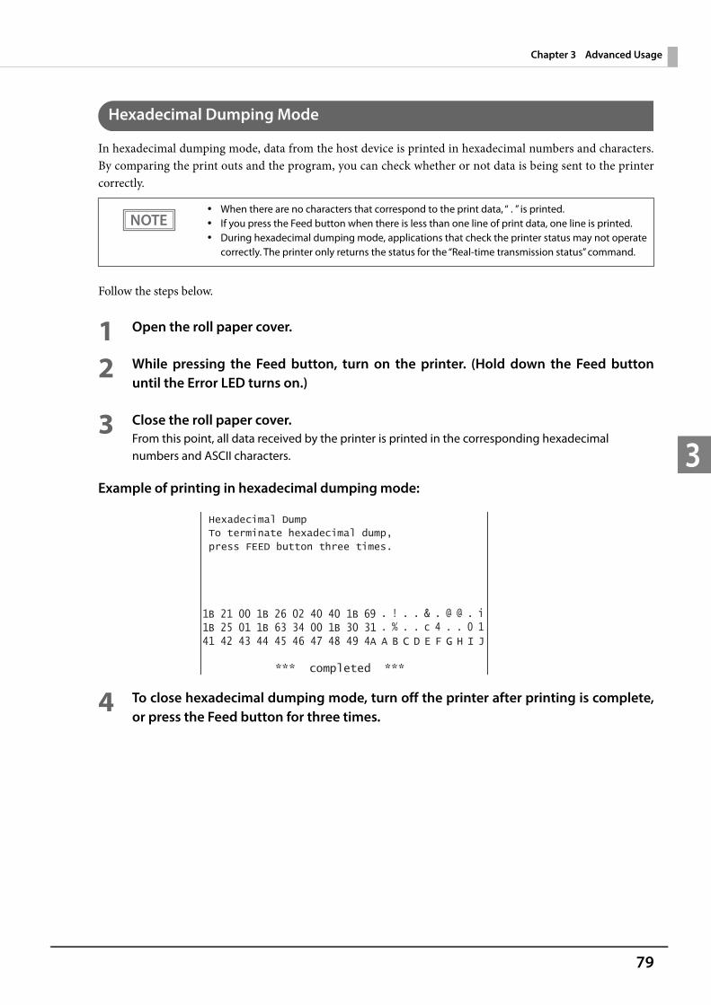
79
Chapter 3 Advanced Usage
3
Hexadecimal Dumping Mode
In hexadecimal dumping mode, data from the host device is printed in hexadecimal numbers and characters.By comparing the print outs and the program, you can check whether or not data is being sent to the printercorrectly.
Follow the steps below.
1 Open the roll paper cover.
2 While pressing the Feed button, turn on the printer. (Hold down the Feed buttonuntil the Error LED turns on.)
3 Close the roll paper cover.From this point, all data received by the printer is printed in the corresponding hexadecimal numbers and ASCII characters.
Example of printing in hexadecimal dumping mode:
4 To close hexadecimal dumping mode, turn off the printer after printing is complete,or press the Feed button for three times.
When there are no characters that correspond to the print data, “ . ” is printed. If you press the Feed button when there is less than one line of print data, one line is printed. During hexadecimal dumping mode, applications that check the printer status may not operate
correctly. The printer only returns the status for the “Real-time transmission status” command.

80
Printing a Status SheetFollow the steps below to check the interface settings.
Using the Status Sheet Button
1 Check that the printer is turned on.Make sure the roll paper cover is closed.
2 If there is a connector cover, remove the cover.See "Attaching the Connector Cover" on page 46 for details on removing the connector cover.
3 Hold down the status sheet button for at least three seconds.The status sheet is printed. After printing, the printer returns to the standard mode.
Using the Feed button
1 Check that the printer is on.
2 Open the roll paper cover.
3 Hold down the Feed button for at least one second.
4 Close the roll paper cover.The status sheet is printed. After printing, the printer returns to the standard mode.
When the power LED is flashing, wait until it remains lit to start printing.
Only the content for the Ethernet and Wi-Fi interface are printed.
Content for the Ethernet, Wi-Fi, and Bluetooth interface are printed.
For firmware version 40.02 or earlier, press and hold for 3 seconds or longer.
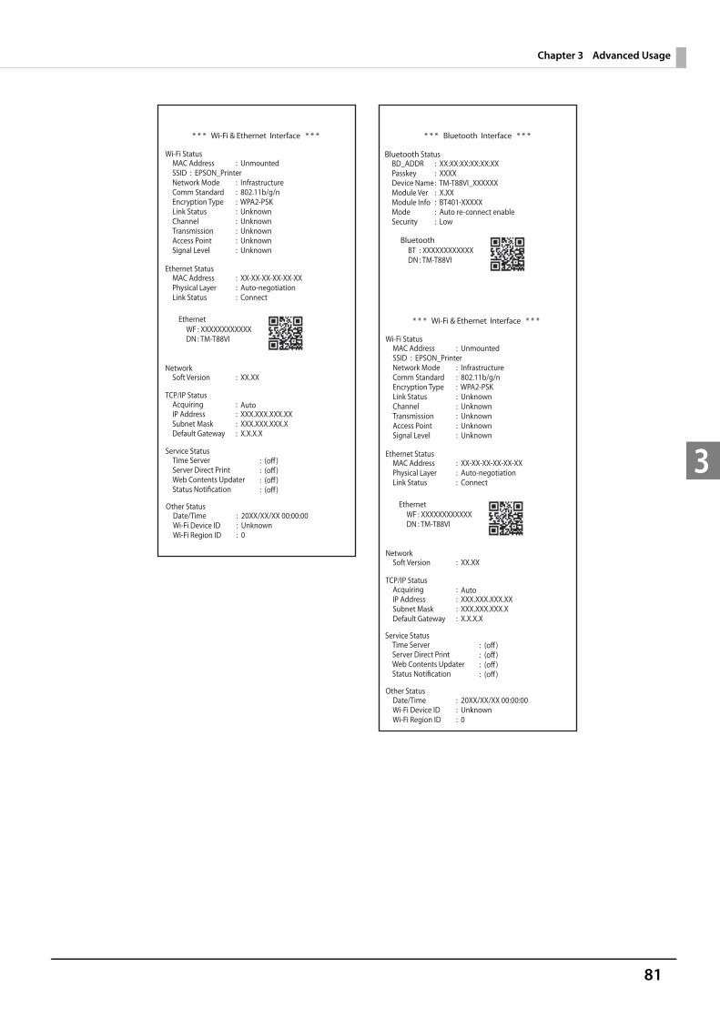
81
Chapter 3 Advanced Usage
3
* * * Bluetooth Interface * * *
Bluetooth StatusBD_ADDRPasskeyDevice NameModule VerModule InfoModeSecurity
: XX:XX:XX:XX:XX:XX: XXXX: TM-T88VI_XXXXXX: X.XX: BT401-XXXXX: Auto re-connect enable: Low
: XXXXXXXXXXXX: TM-T88VI
BTDN
Bluetooth
* * * Wi-Fi & Ethernet Interface * * *
Wi-Fi StatusMAC AddressSSID : EPSON_PrinterNetwork ModeComm StandardEncryption TypeLink StatusChannelTransmissionAccess PointSignal Level
: Unmounted
: Infrastructure: 802.11b/g/n: WPA2-PSK: Unknown: Unknown: Unknown: Unknown: Unknown
Ethernet StatusMAC AddressPhysical LayerLink Status
: XX-XX-XX-XX-XX-XX: Auto-negotiation: Connect
NetworkSoft Version : XX.XX
TCP/IP StatusAcquiringIP AddressSubnet MaskDefault Gateway
: : XXX.XXX.XXX.XX: XXX.XXX.XXX.X: X.X.X.X
: XXXXXXXXXXXX: TM-T88VI
WFDN
Ethernet * * * Wi-Fi & Ethernet Interface * * *
Wi-Fi StatusMAC AddressSSID : EPSON_PrinterNetwork ModeComm StandardEncryption TypeLink StatusChannelTransmissionAccess PointSignal Level
: Unmounted
: Infrastructure: 802.11b/g/n: WPA2-PSK: Unknown: Unknown: Unknown: Unknown: Unknown
Ethernet StatusMAC AddressPhysical LayerLink Status
: XX-XX-XX-XX-XX-XX: Auto-negotiation: Connect
NetworkSoft Version : XX.XX
TCP/IP StatusAcquiringIP AddressSubnet MaskDefault Gateway
: : XXX.XXX.XXX.XX: XXX.XXX.XXX.X: X.X.X.X
Other StatusDate/TimeWi-Fi Device IDWi-Fi Region ID
: 20XX/XX/XX 00:00:00: Unknown: 0
: XXXXXXXXXXXX: TM-T88VI
WFDN
Ethernet
Service Status
Other StatusDate/TimeWi-Fi Device IDWi-Fi Region ID
: 20XX/XX/XX 00:00:00: Unknown: 0
Service Status
Auto
Auto

82
---Server access test result---Device local_printer Model :TM-T88VI Connection :Success network_printer1 Model :TM-Txx IP Address :192.168.192.100 Connection :Success network_printer2 Model :TM-Txx IP Address :192.168.192.101 Connection :Success
Spooler Remaining Jobs :0 job
Server Direct Print Server 1 Access Test :Success Server 2 Access Test :Success Server 3 Access Test :Success
Status Notification Access Test :Success
Web Contents Update Access Test :HTTP Status Code : 404 Update Information Contents Timestamp :Wed Jan 1 00:00:52 2014 Last Update :Wed Jan 1 00:00:53 2014 Update Result :WebContentsSuccess
83
Chapter 3 Advanced Usage
3
Resetting the Interface SettingsFollow the steps below to reset the interface settings.
1 Turn off the printer and close the roll paper cover.
2 If the connector cover is attached, remove the cover.See "Attaching the Connector Cover" on page 46 for details on removing the connector cover.
3 Hold down the status sheet button while turning on the printer.A message is printed indicating that resetting is being performed, and the printer restarts.
You can return the interface settings to their defaults from the Interface Setup mode. See "Interface Setup Mode" on page 76 for details on the Interface Setup mode.
Only network settings are returned to their defaults.
Hold down the status sheet button until the initialization execution message is printed.
84
TM-Intelligent FunctionThis product supports the TM-Intelligent function and provides the following functions. Server direct print Web server Spooler and Print ForwardingYou can set each function in the Setup Utilities. For details on the setting method for Epson TM-T88VI Utility for Windows, see the TM-T88VI Utility User's Manual.You can also download a dedicated manual and sample programs from our homepage.
Server direct print
The server direct function allows this product to acquire print data from a Web server and then print.By including print data in a response to request from this product, the Web server application can print to thisproduct or a TM printer on the network.
The features are as follows. You can acquire print data from three different URLs. Print data is available in ePOS-Print XML format. You can use this product to print to TM printers on a network.
Regarding details on server direct printing, see the Server Direct Printing User's Manual.
Web server
This product is equipped with a Web server, and you can enable this function by saving Web content (HTMLfiles, CSS files, Java script, PHP files, and image data) to the printer.Web server supports the scripting language "PHP" and database "SQLite3". You can enable the following byusing content created in PHP. Creating a dynamic Web page Handling user data by file or database operations
Web content registered to this product can be automatically acquired and updated from a specific URL.
Use the Setup Utilities to register Web content and make settings for updating.
Specifications of the file to be registered Contents such as HTML files, CSS files, PHP files, JavaScript files, certificate files, and image data. Zip the files to be registered all together. The zip file name is arbitrary.
Use one-byte alphanumeric characters (ASCII characters) for a zip file name and sub-foldername.
The maximum size of the files before being zipped is 30 MB. Otherwise, registering fails.
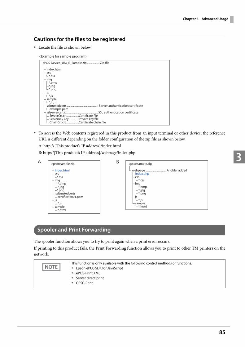
85
Chapter 3 Advanced Usage
3
Cautions for the files to be registered Locate the file as shown below.
To access the Web contents registered in this product from an input terminal or other device, the referenceURL is different depending on the folder configuration of the zip file as shown below.A: http://[This product’s IP address]/index.htmlB: http://[This product’s IP address]/webpage/index.php
Spooler and Print Forwarding
The spooler function allows you to try to print again when a print error occurs.If printing to this product fails, the Print Forwarding function allows you to print to other TM printers on thenetwork.
This function is only available with the following control methods or functions. Epson ePOS SDK for JavaScript ePOS-Print XML Server direct print OFSC-Print
ePOS-Device_UM_E_Sample.zip .................: Zip file
index.html css *.css img *.bmp *.jpg *.png js *.js sample *.html ssltrustedcerts ............................................ : Server authentication certificate example.pem
sslservercerts .............................................. : SSL authentication certificate ServerCrt.crt..................Certificate file ServerKey.key...............Private key file ChainCrt.crt...................Certificate chain file
<Example for sample program>
epsonsample.zip
webpage ............................ : A folder addedindex.php
css *.css img *.bmp *.jpg *.png js *.js sample *.html
epsonsample.zip
index.html css *.css img *.bmp *.jpg
*.png ssltrustedcerts certificate001.pem
js *.js
sample *.html
A B

86

87
Chapter 4 Application Development Information
4
Application Development InformationThis chapter describes how to control the printer and gives information useful for printer application development.
Controlling the PrinterThe printer supports the following command systems: ESC/POS ePOS-Print XML
Users can control the printer by using the aforementioned command, or the following development kits ordrivers. EPSON Advanced Printer Driver (APD) OPOS ADK OPOS ADK for .NET JavaPOS ADK Mac Printer Driver Epson TM/BA Series Thermal Printer Driver Epson ePOS SDK
ePOS-Print XML
ePOS-Print XML is the Epson original control command system for POS printers defined in XML. With ePOS-Print XML commands, you can print in environments where http communication is available and from OSapplications. For detailed information about ePOS-Print XML, see the ePOS-Print XML User's Manual.
ESC/POS
ESC/POS is the Epson original printer command system for POS printers and customer display. With ESC/POScommands, you can directly control all the printer functions, but detailed knowledge of printer specifications orcombination of commands is required, compared to using drivers and applications.For detailed information about ESC/POS commands, see the ESC/POS Command Reference that can beaccessed from the following URL.
https://reference.epson-biz.com/pos/reference/
88
Controlling the Cash DrawerA pulse output is sent to drawer kick connector pin 2 or pin 5, and you can open the drawer.You can also check the open/close status of the drawer by checking the signal level of the drawer kick connectorpin 3.These controls are executed by a driver or by commands.
ESC/POS CommandsPrepare the output command for the specified pulse and the status transmission command.For details, see the ESC/POS Command Reference.
For Windows Printer Drivers (APD)You can set so that the drawer opens at the start/end of printing or start/end of a page. For details, see the manual for drivers.For details on control, see the manual for Status API of the driver.
OPOS (OCX Driver)Register a cash drawer using the SetupPOS Utility, and control using the OpenDrawer method or the DirectIOfunction.For details, see the "EPSON OPOS ADK MANUAL APPLICATION DEVELOPMENT GUIDE Cash Drawer"and the "UnifiedPOS Specification".
OPOS for .NETRegister a cash drawer using the SetupPOS Utility, and control using the OpenDrawer method or the DirectIOfunction.For details, see the "EPSON OPOS ADK for .NET MANUAL Application Development Guide Cash Drawer(EPSON Standard)" and the "UnifiedPOS Specification".
Epson ePOS SDKThe output command for the drawer kick pulse and the status transmission command are provided in eachSDK library. For details, see the user's manuals provided with each SDK.
Whether or not pin 2 or pin 5 operates the drawer kick connector depends on the connected cashdrawer.
You can acquire documents regarding the UnifiedPOS from the following link.https://nrf.com/resources/retail-technology-standards/unifiedpos
89
Chapter 4 Application Development Information
4
Controlling the Built-in BuzzerFor specifications with a built-in buzzer, a pulse output is sent to the operating pin for the drawer kick connector, and the built-in buzzer beeps.You cannot change the volume or the sound emitted, but you can change the buzzing time by changing the signal pulse width.This is controlled by a driver or by commands.
ESC/POS CommandsThe output command for the specified pulse is used.For details, see the ESC/POS Command Reference.
For Windows Printer Drivers (APD)You can set so that the buzzer beeps at the start/end of printing or start/end of a page. For details, see the manual for drivers.For API, the API for opening the drawer is used. For details, see the manual for Status API of the driver.
OPOS (OCX Driver)Register a POS printer using the SetupPOS Utility and control using the DirectIO function.For details, see the "EPSON OPOS ADK MANUAL APPLICATION DEVELOPMENT GUIDE POSPrinter(TM Series)".
OPOS for .NETRegister a POS printer using the SetupPOS Utility and control using the DirectIO function.For details, see the "EPSON OPOS ADK for .NET MANUAL Application Development Guide POSPrinter(TM-T88VI)".
Epson ePOS SDKUse the output command for the drawer kick pulse provided in each SDK library. For details, see the user'smanuals provided with each SDK.
When using a cash drawer operated by pin 5 with a built-in buzzer, you need to change the DIP switchsettings for the buzzer circuit so that the buzzer beeps from a pulse signal for pin 2. For details, see"Setting the Built-in Buzzer (for Model with a Built-in Buzzer)" on page 43.
90
Controlling the Optional External BuzzerYou can set the optional external buzzer to buzz when an error occurs and when an automatic cut off occurs.The buzzer can be buzzed using a driver or a command.You can also set the timing and the beep pattern for the buzzer.
ESC/POS CommandUse the buzzer control command or the output command for the specified pulse.For details, see the ESC/POS Command Reference.
For Windows Printer Drivers (APD)You can set so that the buzzer beeps at the start/end of printing or start/end of a page. For details, see the manual for drivers.For API, use the DirectIO function or the API for opening the drawer. For details, see the manual for Status APIof the drivers.
OPOS (OCX Driver)Register a POS printer using the SetupPOS Utility and control using the DirectIO function.For details, see the "EPSON OPOS ADK MANUAL APPLICATION DEVELOPMENT GUIDE POSPrinter(TM Series)".
OPOS for .NETRegister a POS printer using the SetupPOS Utility and control using the DirectIO function.For details, see the "EPSON OPOS ADK for .NET MANUAL Application Development Guide POSPrinter(TM-T88VI)".
Epson ePOS SDKThe command for the buzzer function is provided in each SDK library. For details, see the user's manuals provided with each SDK.
For details on setting the optional external buzzer, see "Connecting the Optional External Buzzer" onpage 44.

91
Chapter 4 Application Development Information
4
SoftwareThe following software is provided for application development.
Development Kits
*1: OLE technology developed by Microsoft divides software into part blocks. The OPOS driver is presupposed to be used with a development environment, such as Visual Basic, unlike ordinary Windows printer drivers. It is not a driver to be used for printing from commercial applications. You can acquire documents regarding the UnifiedPOS from the following link.https://nrf.com/resources/retail-technology-standards/unifiedpos
Software Description
EPSON OPOS ADK This OCX driver can control POS peripherals using OLE technology.*1
Because controlling POS peripherals with original commands is not required on theapplication side, efficient system development is possible.
EPSON OPOS ADK for .NET The OPOS ADK for .NET is a POS industry standard printer driver compatible with Microsoft POS for .NET. It allows you to develop applications that are compatible
with the UPOS (Unified POS) specification. When developing applications, use a separate development environment such as Microsoft Visual Studio .NET.
EPSON JavaPOS ADK (Windows/Linux)
JavaPOS is the standard specification which defines an architecture and device interface (API) to access various POS devices from a Java based system. Using JavaPOS standard API allows control with Java based applications of functions inherent to each device. A flexible design with Java language and JavaPOS enables many different types of computer systems, such as stand alone or network configuration, to use a same application. You can use JavaPOS to build applications and drivers independently of platforms. This allows flexible configurations using thin clients to meet the system requirements.
Epson ePOS SDK This is a developer kit to control applications, native applications for smart devices,and printers. This includes libraries, manuals, and sample programs.
for Android
for iOS
for Universal Windows apps
for JavaScript
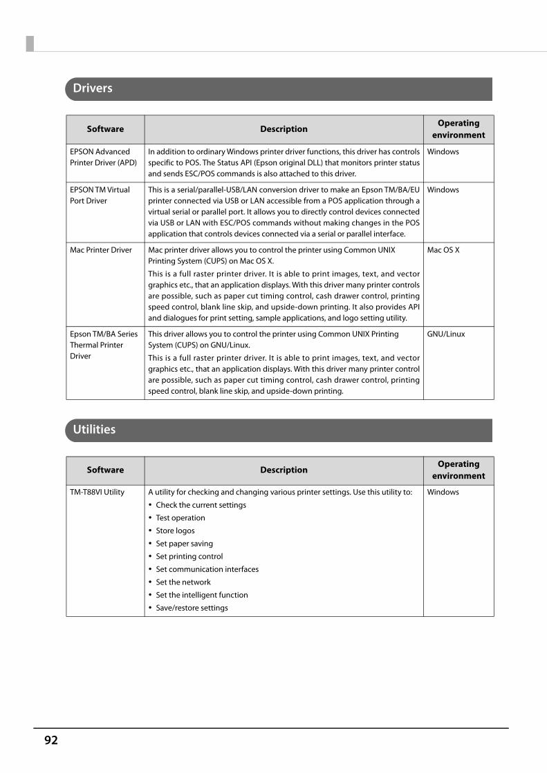
92
Drivers
Utilities
Software DescriptionOperating
environment
EPSON Advanced Printer Driver (APD)
In addition to ordinary Windows printer driver functions, this driver has controlsspecific to POS. The Status API (Epson original DLL) that monitors printer statusand sends ESC/POS commands is also attached to this driver.
Windows
EPSON TM Virtual Port Driver
This is a serial/parallel-USB/LAN conversion driver to make an Epson TM/BA/EUprinter connected via USB or LAN accessible from a POS application through avirtual serial or parallel port. It allows you to directly control devices connectedvia USB or LAN with ESC/POS commands without making changes in the POSapplication that controls devices connected via a serial or parallel interface.
Windows
Mac Printer Driver Mac printer driver allows you to control the printer using Common UNIX Printing System (CUPS) on Mac OS X.
This is a full raster printer driver. It is able to print images, text, and vectorgraphics etc., that an application displays. With this driver many printer controlsare possible, such as paper cut timing control, cash drawer control, printingspeed control, blank line skip, and upside-down printing. It also provides APIand dialogues for print setting, sample applications, and logo setting utility.
Mac OS X
Epson TM/BA Series Thermal Printer Driver
This driver allows you to control the printer using Common UNIX Printing System (CUPS) on GNU/Linux.
This is a full raster printer driver. It is able to print images, text, and vectorgraphics etc., that an application displays. With this driver many printer controlare possible, such as paper cut timing control, cash drawer control, printingspeed control, blank line skip, and upside-down printing.
GNU/Linux
Software DescriptionOperating
environment
TM-T88VI Utility A utility for checking and changing various printer settings. Use this utility to:
Check the current settings
Test operation
Store logos
Set paper saving
Set printing control
Set communication interfaces
Set the network
Set the intelligent function
Save/restore settings
Windows

93
Chapter 4 Application Development Information
4
*: Supported by Ver. 3.2.0 or later.
Others
Download
You can obtain software and manuals from one of the following URLs.For customers in North America, go to the following web site and follow the on-screen instructions.
http://www.epson.com/support/For customers in other countries, go to the following web site:
http://download.epson-biz.com/?service=pos
Epson TM Utility A utility that can be downloaded from App Store or Google Play. Use this to per-form wireless connection setup and change settings on the printer from iOSand Android devices. This utility also comes with the following sample printingfunctions:
Sample receipt printing
Customized receipt printing
Printer status display
Quick pairing by NFC/QR code
Easy print by NFC/QR code
Firmware update*
iOS, Android
EpsonNet Config A network setting tool for Epson network products. Windows, Mac
EPSON TM Bluetooth® Connector
Use to pair a Bluetooth printer and associate the generated Bluetooth port withthat used by the driver and applications.
Windows
Epson DeploymentTool
Use to make network and printer settings simultaneously. Allows you to makesettings efficiently at the time of introducing TM printers for the first time, orwhen configuring multiple TM printers at the same time.
Windows
Epson MonitoringTool
Use to check a list of status for the Epson printers connected to the network.
You can also update certificates for multiple printers used for WPA2-Enterprisein a batch.
Windows
TM-T88VI Printer Model Setting Utility
This tool allows you to change the model name for the TM-T88VI to TM-T88V orTM-T88IV.
Windows
BmpToRaster You can convert BMP image files to multi tone or black and white print command data.
Windows
EPSON TMUSB Identifier Utility
This tool allows you to change the USB identification code (USB Serial No.). Setting an identification code before replacement makes it easy to perform replacement if a malfunction occurs.
Windows
TM-T88VI Firmware Updater
This tool allows you to update the firmware for the TM-T88VI. Windows
Manual Description
ePOS-Print XML User's Manual Describes ePOS-Print XML statements. This manual comes with sample programs.
TM-T88VI/TM-T88VI-iHUB WebConfig API User's Manual
Describes the API for setting this product's TM-Intelligent function. Refer to this manualwhen using the API from your application to acquire or change settings.

94
Application Development and Distribution for iOSIf registering an application that uses Bluetooth in the App Store, Epson must submit an application to Apple inadvance. Please apply for each application you want to register in the App Store from the URL below.
https://c4b.epson-biz.com/ais/E/
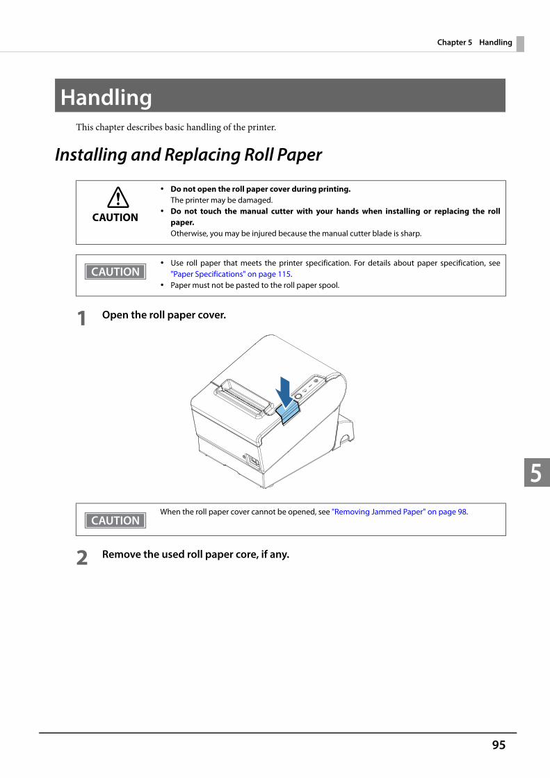
95
Chapter 5 Handling
5
HandlingThis chapter describes basic handling of the printer.
Installing and Replacing Roll Paper
1 Open the roll paper cover.
2 Remove the used roll paper core, if any.
CAUTION
Do not open the roll paper cover during printing.The printer may be damaged.
Do not touch the manual cutter with your hands when installing or replacing the rollpaper.Otherwise, you may be injured because the manual cutter blade is sharp.
Use roll paper that meets the printer specification. For details about paper specification, see"Paper Specifications" on page 115.
Paper must not be pasted to the roll paper spool.
When the roll paper cover cannot be opened, see "Removing Jammed Paper" on page 98.
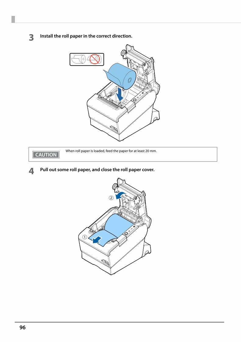
96
3 Install the roll paper in the correct direction.
4 Pull out some roll paper, and close the roll paper cover.
When roll paper is loaded, feed the paper for at least 20 mm.
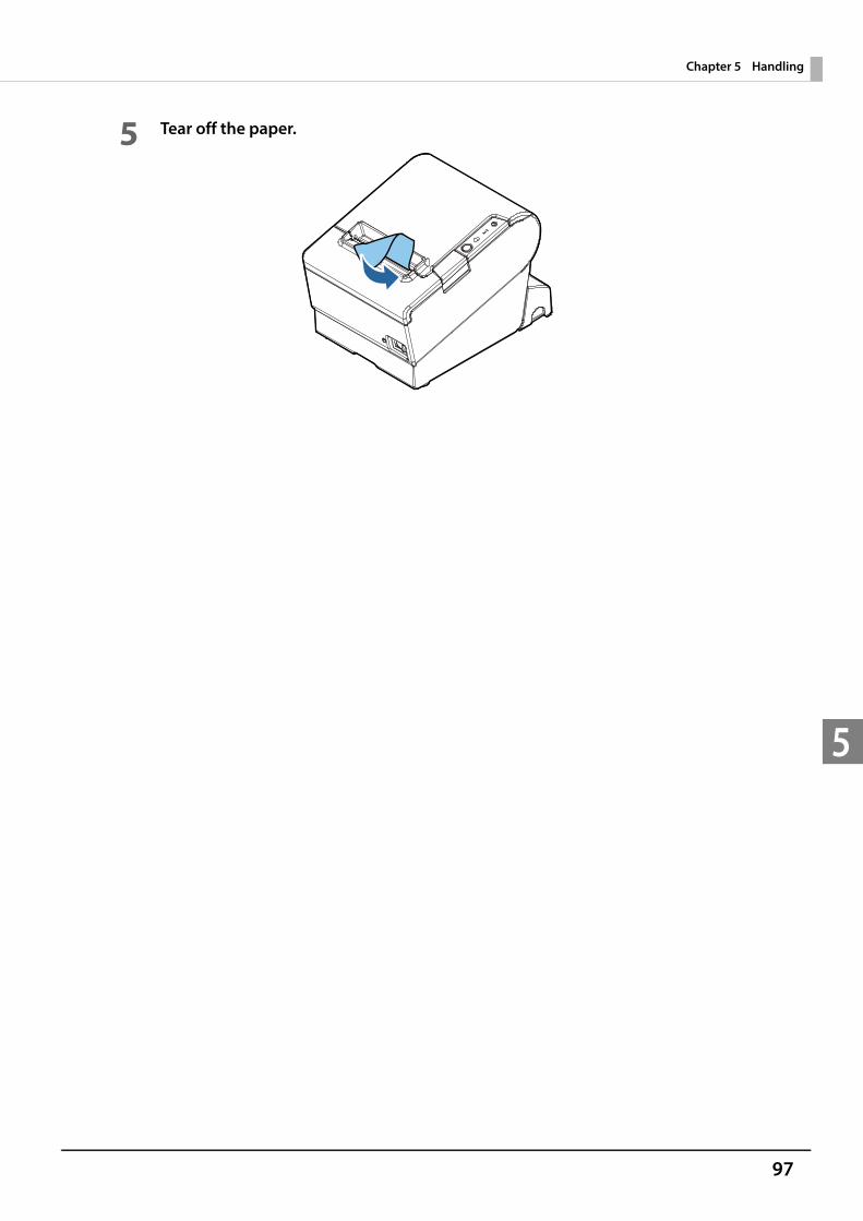
97
Chapter 5 Handling
5
5 Tear off the paper.
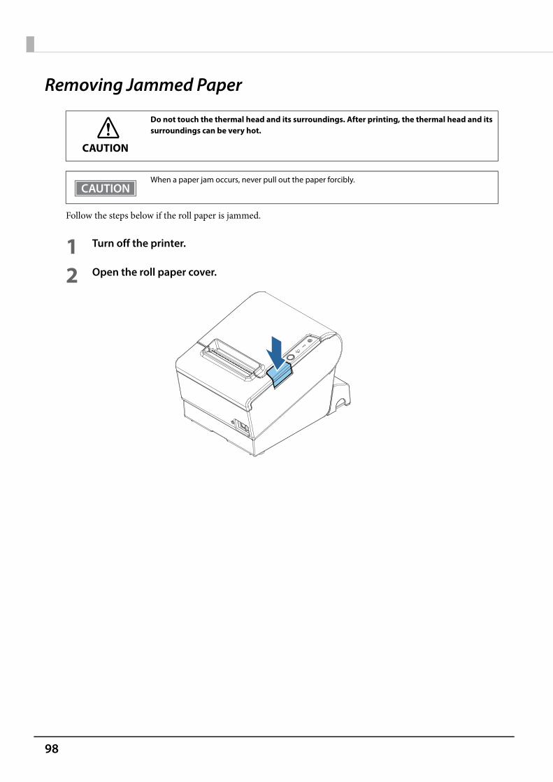
98
Removing Jammed Paper
Follow the steps below if the roll paper is jammed.
1 Turn off the printer.
2 Open the roll paper cover.
CAUTION
Do not touch the thermal head and its surroundings. After printing, the thermal head and itssurroundings can be very hot.
When a paper jam occurs, never pull out the paper forcibly.
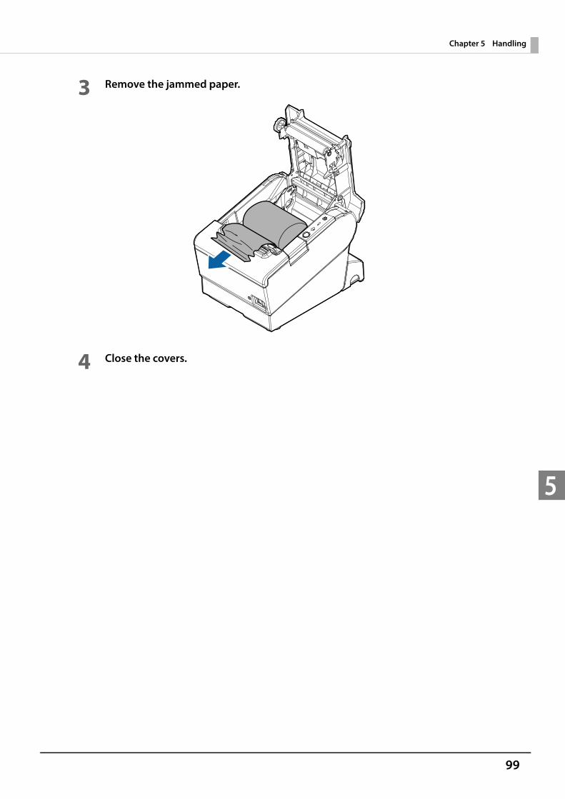
99
Chapter 5 Handling
5
3 Remove the jammed paper.
4 Close the covers.
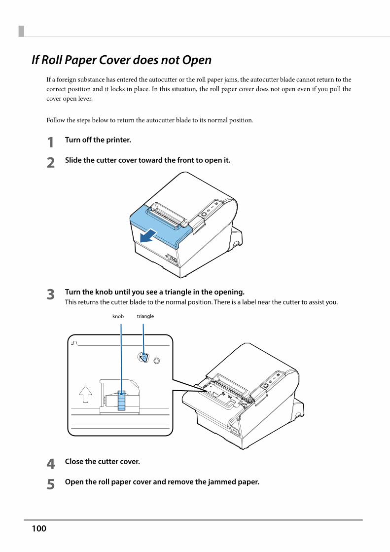
100
If Roll Paper Cover does not OpenIf a foreign substance has entered the autocutter or the roll paper jams, the autocutter blade cannot return to thecorrect position and it locks in place. In this situation, the roll paper cover does not open even if you pull thecover open lever.
Follow the steps below to return the autocutter blade to its normal position.
1 Turn off the printer.
2 Slide the cutter cover toward the front to open it.
3 Turn the knob until you see a triangle in the opening.This returns the cutter blade to the normal position. There is a label near the cutter to assist you.
4 Close the cutter cover.
5 Open the roll paper cover and remove the jammed paper.
knob triangle

101
Chapter 5 Handling
5
Cleaning the Printer
Cleaning the Printer Case
Be sure to turn off the printer, and wipe the dirt off the printer case with a dry cloth or a damp cloth. Be sure tounplug the AC cable while cleaning.
Cleaning the Thermal Head/Platen Roller
Epson recommends cleaning the thermal head periodically (generally every 3 months) to maintain receipt printquality.Depending on the roll paper used, paper dust may stick to the platen roller and cause an irregular paper feed. Toremove the paper dust, clean the platen roller with a cotton swab moistened with water. Turn on the printerpower only after the water has completely dried.
Turn off the printer, open the roll paper cover, and clean the thermal elements of the thermal head with a cottonswab moistened with an alcohol solvent (ethanol or IPA).
Never clean the product with alcohol, benzine, thinner, or other such solvents. Doing so may damage or break the parts made of plastic and rubber.
After printing, the thermal head can be very hot. Do not touch it and let it cool before youclean it.
Do not damage the thermal head by touching it with your fingers or any hard object.
Thermal head Platen roller

102
Preparing for TransportFollow the steps below to transport the printer.
1 Turn off the printer.
2 Remove the power supply connector.
3 Remove the roll paper.
4 Pack the printer upright.
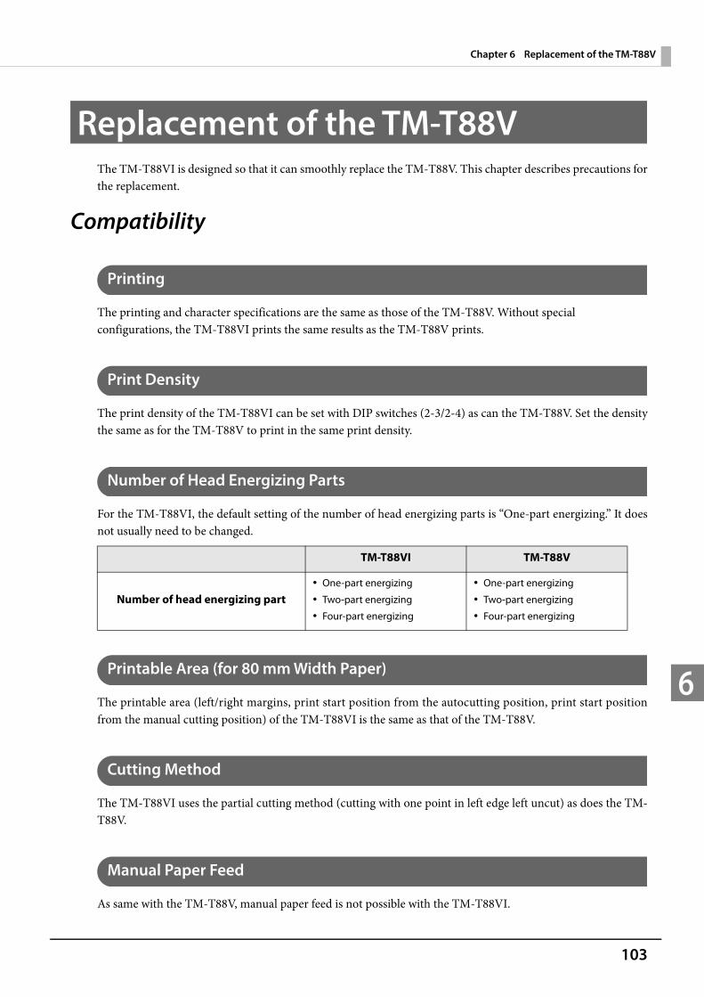
103
Chapter 6 Replacement of the TM-T88V
6
Replacement of the TM-T88VThe TM-T88VI is designed so that it can smoothly replace the TM-T88V. This chapter describes precautions forthe replacement.
Compatibility
Printing
The printing and character specifications are the same as those of the TM-T88V. Without special configurations, the TM-T88VI prints the same results as the TM-T88V prints.
Print Density
The print density of the TM-T88VI can be set with DIP switches (2-3/2-4) as can the TM-T88V. Set the densitythe same as for the TM-T88V to print in the same print density.
Number of Head Energizing Parts
For the TM-T88VI, the default setting of the number of head energizing parts is “One-part energizing.” It doesnot usually need to be changed.
Printable Area (for 80 mm Width Paper)
The printable area (left/right margins, print start position from the autocutting position, print start positionfrom the manual cutting position) of the TM-T88VI is the same as that of the TM-T88V.
Cutting Method
The TM-T88VI uses the partial cutting method (cutting with one point in left edge left uncut) as does the TM-T88V.
Manual Paper Feed
As same with the TM-T88V, manual paper feed is not possible with the TM-T88VI.
TM-T88VI TM-T88V
Number of head energizing part One-part energizing
Two-part energizing
Four-part energizing
One-part energizing
Two-part energizing
Four-part energizing
104
Receive Buffer
You can set the receive buffer of the TM-T88VI to 4KB or 45 bytes with DIP switch 1-2 as with the TM-T88V.The buffer full condition and buffer full release condition of the TM-T88VI are the same as those of theTM-T88V.
Memory Capacity
The sizes of the download buffer and NV graphics data of the TM-T88VI are the same as those of theTM-T88V.
Electrical Characteristics
The operating voltage of the TM-T88VI is DC24 ± 7%, the same as the TM-T88V. The current consumption differs, depending on the print duty. When you set the print speed to 350 mm/s, the amount of electricity consumed increases.
DIP Switches
The functional assignments of DIP switches for the TM-T88VI differ from the TM-T88V. See "Setting the DIPSwitches" on page 53 for more details.
Printer Status
The TM-T88VI goes to the same status under the same conditions as the TM-T88V. You can replace theTM-T88V with the TM-T88VI without modifying applications.
Logo Registration
The TM-T88VI can register logos in the NV memory (NVRAM) with the Setup Utilities.
Driver Compatibility
You can operate the TM-T88VI with a driver for the TM-T88V.
USB Low Power Consumption Mode
With the TM-T88VI, you can enable the USB low power consumption mode in the software setting mode.

105
Chapter 6 Replacement of the TM-T88V
6
Maintenance Counter
The TM-T88VI has a maintenance counter just as the TM-T88V has.
Buzzer
TM-T88VI is available with a built-in buzzer or without the buzzer. Even if you purchase the one without thebuzzer, you can attach an optional external buzzer. You can beep the buzzer with the pulse signal using acommand.
Power Supply Box
The optional power supply box (OT-BX88VI) is available to be attached under the TM-T88VI to hold thepower unit.
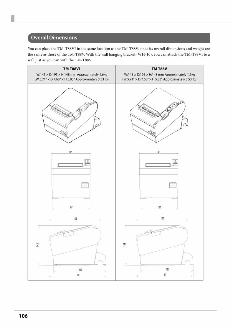
106
Overall Dimensions
You can place the TM-T88VI in the same location as the TM-T88V, since its overall dimensions and weight arethe same as those of the TM-T88V. With the wall hanging bracket (WH-10), you can attach the TM-T88VI to awall just as you can with the TM-T88V.
TM-T88VI W:145 × D:195 × H:148 mm Approximately 1.6kg
{W:5.71" × D:7.68" × H:5.83" Approximately 3.53 lb}
TM-T88V W:145 × D:195 × H:148 mm Approximately 1.6kg
{W:5.71" × D:7.68" × H:5.83" Approximately 3.53 lb}
145
141
145
141
148
195
211
195
148
195
211
195
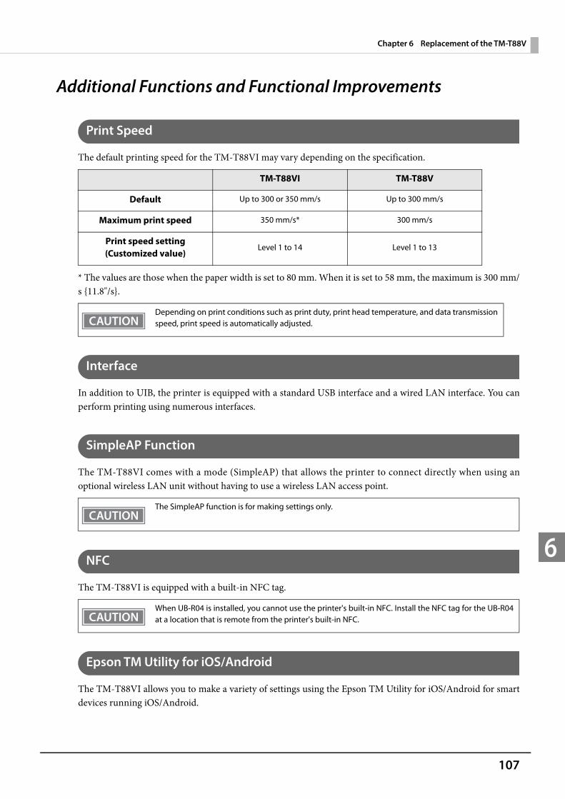
107
Chapter 6 Replacement of the TM-T88V
6
Additional Functions and Functional Improvements
Print Speed
The default printing speed for the TM-T88VI may vary depending on the specification.
* The values are those when the paper width is set to 80 mm. When it is set to 58 mm, the maximum is 300 mm/s {11.8"/s}.
Interface
In addition to UIB, the printer is equipped with a standard USB interface and a wired LAN interface. You canperform printing using numerous interfaces.
SimpleAP Function
The TM-T88VI comes with a mode (SimpleAP) that allows the printer to connect directly when using anoptional wireless LAN unit without having to use a wireless LAN access point.
NFC
The TM-T88VI is equipped with a built-in NFC tag.
Epson TM Utility for iOS/Android
The TM-T88VI allows you to make a variety of settings using the Epson TM Utility for iOS/Android for smartdevices running iOS/Android.
TM-T88VI TM-T88V
Default Up to 300 or 350 mm/s Up to 300 mm/s
Maximum print speed 350 mm/s* 300 mm/s
Print speed setting(Customized value)
Level 1 to 14 Level 1 to 13
Depending on print conditions such as print duty, print head temperature, and data transmissionspeed, print speed is automatically adjusted.
The SimpleAP function is for making settings only.
When UB-R04 is installed, you cannot use the printer's built-in NFC. Install the NFC tag for the UB-R04at a location that is remote from the printer's built-in NFC.

108
Software Settings
For the TM-T88VI, the following software setting functions are added. Command execution during offline Amount of top margin by backfeed Interface switch waiting time Main connection interface LED indicator when I/F starting Number of digits emulation mode Select autocutter error release method
TM-Intelligent function
The TM-T88VI supports the following TM-Intelligent function. Supports Server Direct Print that sends a request for print data from the product to the Web server at regular
intervals. Since print data can be saved in the spooler, applications can be released from processing print jobs
regardless of the printer status. When a network printer is registered while printing from Epson ePOS SDK for JavaScript, print forwarding
process can be realized. Also, if the printer is not ready to print, you can print from another printer. Equipped with Web server that supports the scripting language "PHP" and database "SQLite3".
For detailed information about the software settings, see "Software Settings" on page 59.
The spooler and print forwarding function is only available with the following control methods orfunctions. Epson ePOS SDK for JavaScript ePOS-Print XML Server direct print OFSC-Print
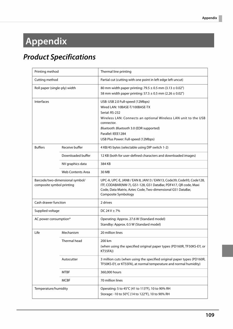
109
Appendix
Appendix
Product Specifications
Printing method Thermal line printing
Cutting method Partial cut (cutting with one point in left edge left uncut)
Roll paper (single-ply) width 80 mm width paper printing: 79.5 ± 0.5 mm (3.13 ± 0.02")
58 mm width paper printing: 57.5 ± 0.5 mm (2.26 ± 0.02")
Interfaces USB: USB 2.0 Full-speed (12Mbps)
Wired LAN: 10BASE-T/100BASE-TX
Serial: RS-232
Wireless LAN: Connects an optional Wireless LAN unit to the USBconnector.
Bluetooth: Bluetooth 3.0 (EDR supported)
Parallel: IEEE1284
USB Plus Power: Full-speed (12Mbps)
Buffers Receive buffer 4 KB/45 bytes (selectable using DIP switch 1-2)
Downloaded buffer 12 KB (both for user-defined characters and downloaded images)
NV graphics data 384 KB
Web Contents Area 30 MB
Barcode/two-dimensional symbol/composite symbol printing
UPC-A, UPC-E, JAN8 / EAN 8, JAN13 / EAN13, Code39, Code93, Code128, ITF, CODABAR(NW-7), GS1-128, GS1 DataBar, PDF417, QR code, Maxi Code, Data Matrix, Aztec Code, Two-dimensional GS1 DataBar, Composite Symbology
Cash drawer function 2 drives
Supplied voltage DC 24 V ± 7%
AC power consumption* Operating: Approx. 27.6 W (Standard model)
Standby: Approx. 0.5 W (Standard model)
Life Mechanism 20 million lines
Thermal head 200 km
(when using the specified original paper types (PD160R, TF50KS-EY, orKT55FA))
Autocutter 3 million cuts (when using the specified original paper types (PD160R,TF50KS-EY, or KT55FA), at normal temperature and normal humidity)
MTBF 360,000 hours
MCBF 70 million lines
Temperature/humidity Operating: 5 to 45°C {41 to 113°F}, 10 to 90% RH
Storage: -10 to 50°C {14 to 122°F}, 10 to 90% RH
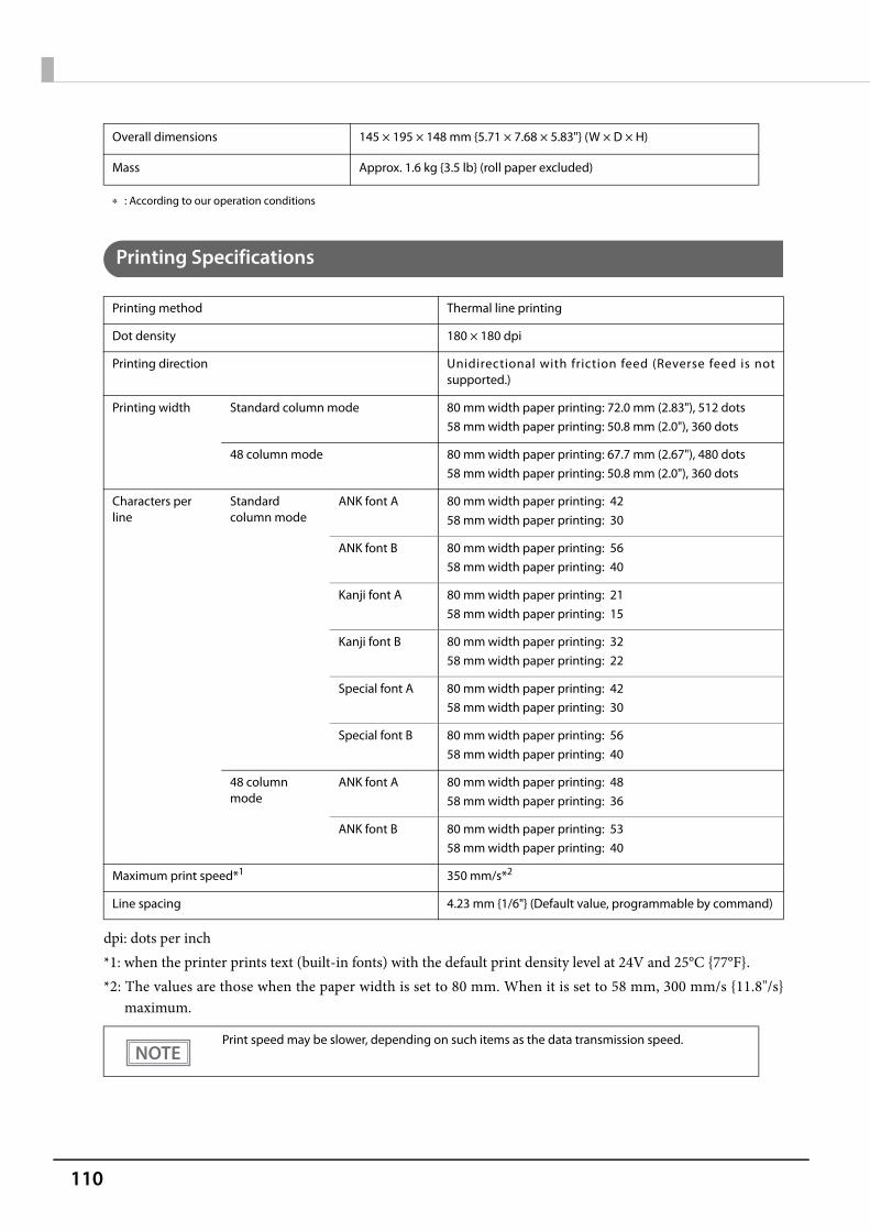
110
: According to our operation conditions
Printing Specifications
dpi: dots per inch*1: when the printer prints text (built-in fonts) with the default print density level at 24V and 25°C {77°F}.*2: The values are those when the paper width is set to 80 mm. When it is set to 58 mm, 300 mm/s {11.8"/s}
maximum.
Overall dimensions 145 × 195 × 148 mm {5.71 × 7.68 × 5.83"} (W × D × H)
Mass Approx. 1.6 kg {3.5 lb} (roll paper excluded)
Printing method Thermal line printing
Dot density 180 × 180 dpi
Printing direction Unidirectional with friction feed (Reverse feed is notsupported.)
Printing width Standard column mode 80 mm width paper printing: 72.0 mm (2.83"), 512 dots58 mm width paper printing: 50.8 mm (2.0"), 360 dots
48 column mode 80 mm width paper printing: 67.7 mm (2.67"), 480 dots58 mm width paper printing: 50.8 mm (2.0"), 360 dots
Characters per line
Standard column mode
ANK font A 80 mm width paper printing: 4258 mm width paper printing: 30
ANK font B 80 mm width paper printing: 5658 mm width paper printing: 40
Kanji font A 80 mm width paper printing: 2158 mm width paper printing: 15
Kanji font B 80 mm width paper printing: 3258 mm width paper printing: 22
Special font A 80 mm width paper printing: 4258 mm width paper printing: 30
Special font B 80 mm width paper printing: 5658 mm width paper printing: 40
48 column mode
ANK font A 80 mm width paper printing: 4858 mm width paper printing: 36
ANK font B 80 mm width paper printing: 5358 mm width paper printing: 40
Maximum print speed*1 350 mm/s*2
Line spacing 4.23 mm {1/6"} (Default value, programmable by command)
Print speed may be slower, depending on such items as the data transmission speed.

111
Appendix
Character Specifications
Note:1. Space between characters is not included.2. Characters can be scaled up to 64 times as large as the standard size.
Number of characters Alphanumeric characters: 95
Extended graphics: 128 × 43 pages (including user-definedpage)
International characters: 18 sets
GB18030-2000: 28,533 (for Simplified Chinese characters model)
Big 5: 13,535 (for Traditional Chinese characters model)
Korean Kanji (KC C5601): 8,366 (for Korean model)
Thai character: 3-pass printing font (for South Asia model)128 characters x 3 pages (133 character types)
Vietnam character (for South Asia model)128 characters x 2 pages (135 character types)
Character structure
(W x H dots)
Standard column mode
ANK font A 12 × 24 dots (Right-side dot space: 2)
ANK font B 9 × 17 dots (Right-side dot space: 2)
Kanji font A 24 × 24 dots (Right-side dot space: 0)
Kanji font B 16 × 16 dots (Right-side dot space: 0)
Special font A 12 × 24 dots (Right-side dot space: 2)
Special font B 9 × 24 dots (Right-side dot space: 2)
48 column mode
ANK font A 10 × 24 dots (Right-side dot space: 1)
ANK font B 9 × 17 dots (Right-side dot space: 2)
Character size
(W x H)
Standard column mode
ANK font A 1.41 × 3.39 mm {0.06 × 0.13"}
ANK font B 0.99 × 2.40 mm {0.04 × 0.09"}
Kanji font A 3.39 × 3.39 mm {0.13 × 0.13"}
Kanji font B 2.26 × 2.26 mm {0.09 × 0.09"}
Special font A 1.41 × 3.39 mm {0.06 × 0.13"}
Special font B 0.99 × 3.39 mm {0.04 × 0.13"}
48 column mode
ANK font A 1.27 × 3.39 mm {0.05 × 0.13"}
ANK font B 0.99 × 2.40 mm {0.04 × 0.09"}
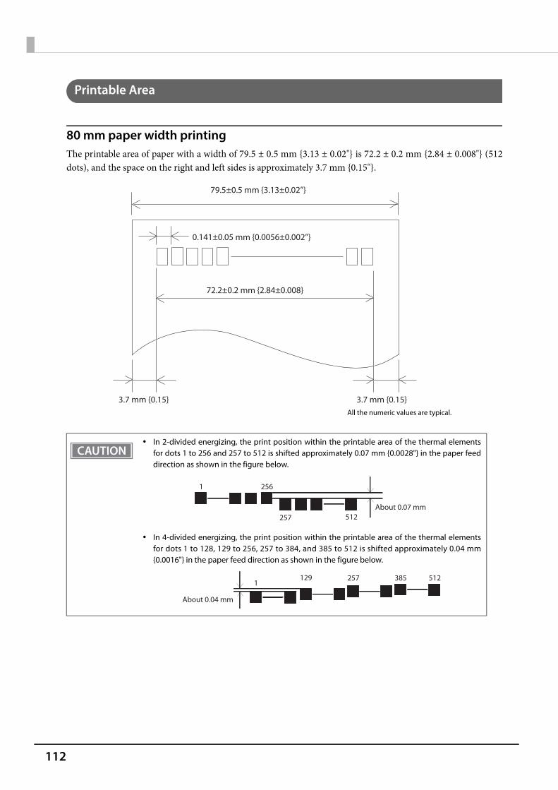
112
Printable Area
80 mm paper width printingThe printable area of paper with a width of 79.5 ± 0.5 mm {3.13 ± 0.02"} is 72.2 ± 0.2 mm {2.84 ± 0.008"} (512dots), and the space on the right and left sides is approximately 3.7 mm {0.15"}.
In 2-divided energizing, the print position within the printable area of the thermal elementsfor dots 1 to 256 and 257 to 512 is shifted approximately 0.07 mm {0.0028"} in the paper feeddirection as shown in the figure below.
In 4-divided energizing, the print position within the printable area of the thermal elementsfor dots 1 to 128, 129 to 256, 257 to 384, and 385 to 512 is shifted approximately 0.04 mm{0.0016"} in the paper feed direction as shown in the figure below.
0.141±0.05 mm {0.0056±0.002”}
79.5±0.5 mm {3.13±0.02”}
72.2±0.2 mm {2.84±0.008}
3.7 mm {0.15} 3.7 mm {0.15}All the numeric values are typical.
2561
257 512About 0.07 mm
1291
512385257
About 0.04 mm
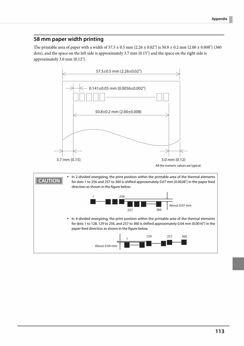
113
Appendix
58 mm paper width printingThe printable area of paper with a width of 57.5 ± 0.5 mm {2.26 ± 0.02"} is 50.8 ± 0.2 mm {2.00 ± 0.008"} (360 dots), and the space on the left side is approximately 3.7 mm {0.15"} and the space on the right side is approximately 3.0 mm {0.12"}.
In 2-divided energizing, the print position within the printable area of the thermal elementsfor dots 1 to 256 and 257 to 360 is shifted approximately 0.07 mm {0.0028"} in the paper feeddirection as shown in the figure below.
In 4-divided energizing, the print position within the printable area of the thermal elementsfor dots 1 to 128, 129 to 256, and 257 to 360 is shifted approximately 0.04 mm {0.0016"} in thepaper feed direction as shown in the figure below.
0.141±0.05 mm {0.0056±0.002”}
57.5±0.5 mm {2.26±0.02”}
50.8±0.2 mm {2.00±0.008}
3.7 mm {0.15} 3.0 mm {0.12}All the numeric values are typical.
2561
257 360About 0.07 mm
1291
360257
About 0.04 mm
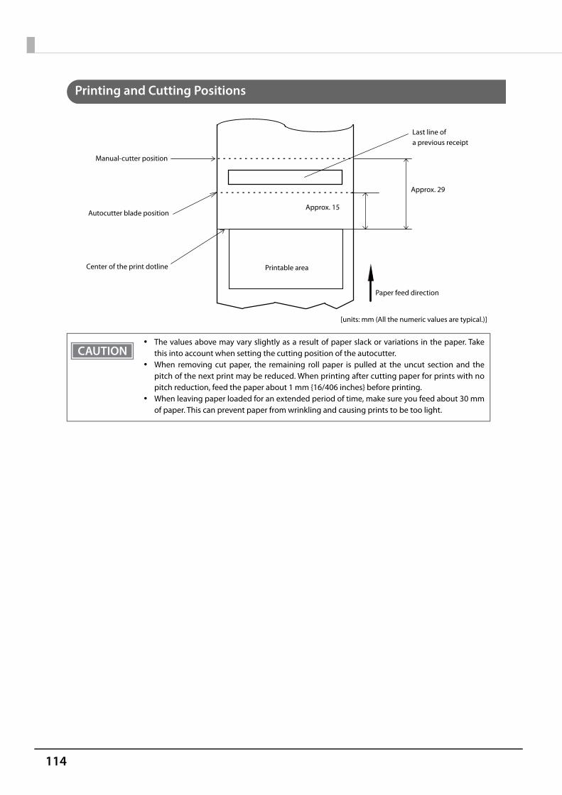
114
Printing and Cutting Positions
The values above may vary slightly as a result of paper slack or variations in the paper. Takethis into account when setting the cutting position of the autocutter.
When removing cut paper, the remaining roll paper is pulled at the uncut section and thepitch of the next print may be reduced. When printing after cutting paper for prints with nopitch reduction, feed the paper about 1 mm {16/406 inches} before printing.
When leaving paper loaded for an extended period of time, make sure you feed about 30 mmof paper. This can prevent paper from wrinkling and causing prints to be too light.
Autocutter blade position
Approx. 29
Approx. 15
Manual-cutter position
Center of the print dotline
[units: mm (All the numeric values are typical.)]
Paper feed direction
Printable area
Last line of a previous receipt

115
Appendix
Paper Specifications
Paper types Specified thermal paper
Form Roll paper
Size Roll paper diameter 83 mm {3.27"} maximum
Roll paper spool Inside: 12 mm {0.47"}, Outside: 18 mm {0.71"}
Roll width when taken up 80 mm width paper printing: 80 + 0.5/-1.0 mm
58 mm width paper printing: 58 + 0.5/-1.0 mm
Paper width 80 mm width paper printing: 79.5 ± 0.5 mm
58 mm width paper printing: 57.5 ± 0.5 mm
Specified original paper type P30521, P30523, P31523, P35524 (Kanzaki Specialty Papers)
AF50KS-E (Jujo Thermal Oy)
F5041 (Mitsubishi HiTec Paper Flensburg GmbH)
KT55FA, KT48FA (Koehler Paper Group)
Epson Certified Media List for Thermal Receipt Printers
☞ https://download.epson-biz.com/?content=sht_tm_media
Paper must not be pasted to the roll paper spool. The remaining amount of the roll paper when a roll paper near-end is detected differs
depending on the spool type.

116
Electrical Characteristics
Supply voltage DC 24V ± 7%
Current consumption
(at 24V, 25°C, normal print density)
Standby Mean: Approximately 0.015A
Maximum 1A for drawer kick driving.
Operating Mean: Approximately 1.8A
Note: When print ratio is approximately 18%
Continuous printing for 50 lines (repeating 20H-7FH) Font A 42 columns ASCII character
5 line feeding
Autocutting
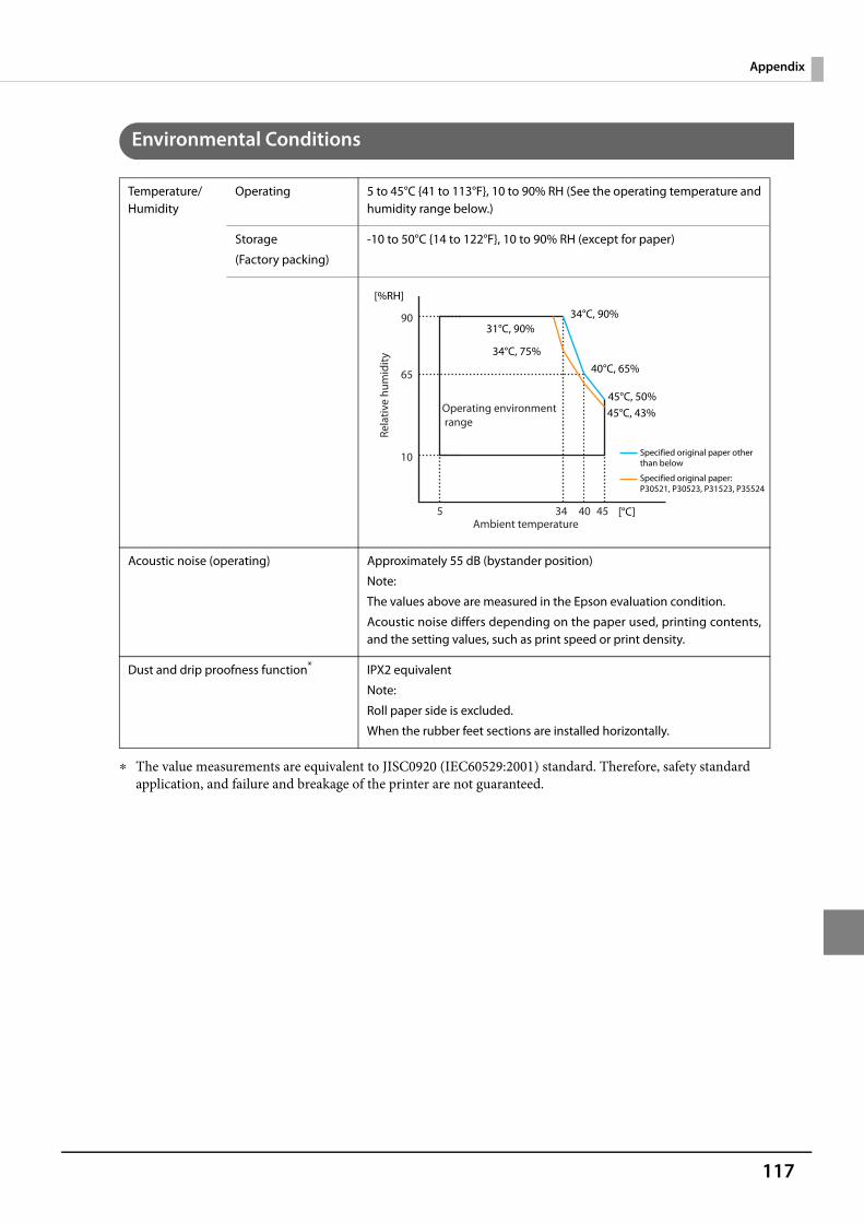
117
Appendix
Environmental Conditions
The value measurements are equivalent to JISC0920 (IEC60529:2001) standard. Therefore, safety standard application, and failure and breakage of the printer are not guaranteed.
Temperature/Humidity
Operating 5 to 45°C {41 to 113°F}, 10 to 90% RH (See the operating temperature andhumidity range below.)
Storage
(Factory packing)
-10 to 50°C {14 to 122°F}, 10 to 90% RH (except for paper)
Acoustic noise (operating) Approximately 55 dB (bystander position)
Note:
The values above are measured in the Epson evaluation condition.
Acoustic noise differs depending on the paper used, printing contents,and the setting values, such as print speed or print density.
Dust and drip proofness function* IPX2 equivalent
Note:
Roll paper side is excluded.
When the rubber feet sections are installed horizontally.
Rela
tive
hum
idity
Operating environment range
90
65
10
5 34 40 45Ambient temperature
[%RH]
34°C, 90%
40°C, 65%
45°C, 50%
[°C]
31°C, 90%
34°C, 75%
45°C, 43%
Specified original paper other than below
Specified original paper:P30521, P30523, P31523, P35524
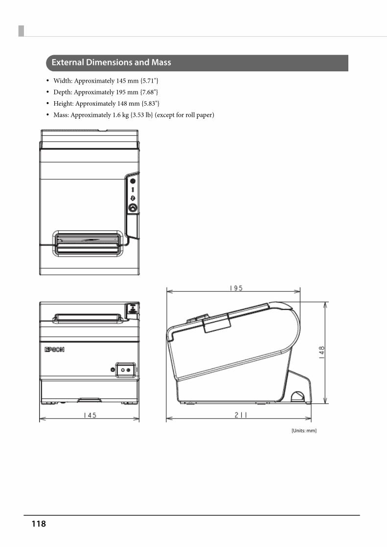
118
External Dimensions and Mass
Width: Approximately 145 mm {5.71"} Depth: Approximately 195 mm {7.68"} Height: Approximately 148 mm {5.83"} Mass: Approximately 1.6 kg {3.53 lb} (except for roll paper)
[Units: mm]
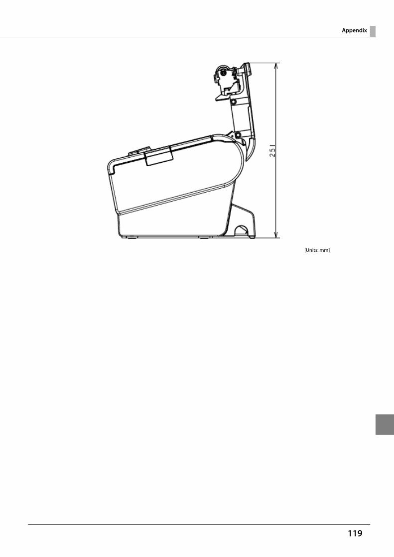
119
Appendix
[Units: mm]

120
Network Printer
The TM-Intelligent function supports the following printers as network printers.
* TM-T88IV compatible mode is not supported.
World wide
models
Simplified Chinese models
Traditional Chinese models
South Asia models
Korean models
TM-T88VI ✔ ✔ ✔ ✔ ✔
TM-m10 ✔ ✔ ✔ ✔ ✔
TM-m30 ✔ ✔ ✔ ✔ ✔
TM-T88V-i ✔ ✔ ✔ ✔ ✔
TM-T70-i ✔ ✔ ✔ ✔ ✔
TM-T20II-i ✔ - - - -
TM-T82II-i - ✔ ✔ ✔ -
TM-T83II-i - - - - ✔
TM-U220-i ✔ - - - -
TM-T88V* ✔ ✔ ✔ ✔ ✔
TM-T88IV ✔ ✔ ✔ ✔ ✔
TM-T70 ✔ ✔ ✔ ✔ ✔
TM-T70II ✔ ✔ ✔ ✔ ✔
TM-T90 ✔ - ✔ ✔ -
TM-L90 ✔ ✔ ✔ - ✔
TM-P60II ✔ - - - -
TM-P60II Peeler ✔ - - - -
TM-T20 ✔ - - - -
TM-T20II ✔ - - - -
TM-T82II ✔ ✔ ✔ ✔ -
TM-T83II - - - - ✔
TM-P80 ✔ - - - -
TM-P20 ✔ - - - -
TM-U220 ✔ ✔ ✔ ✔ ✔
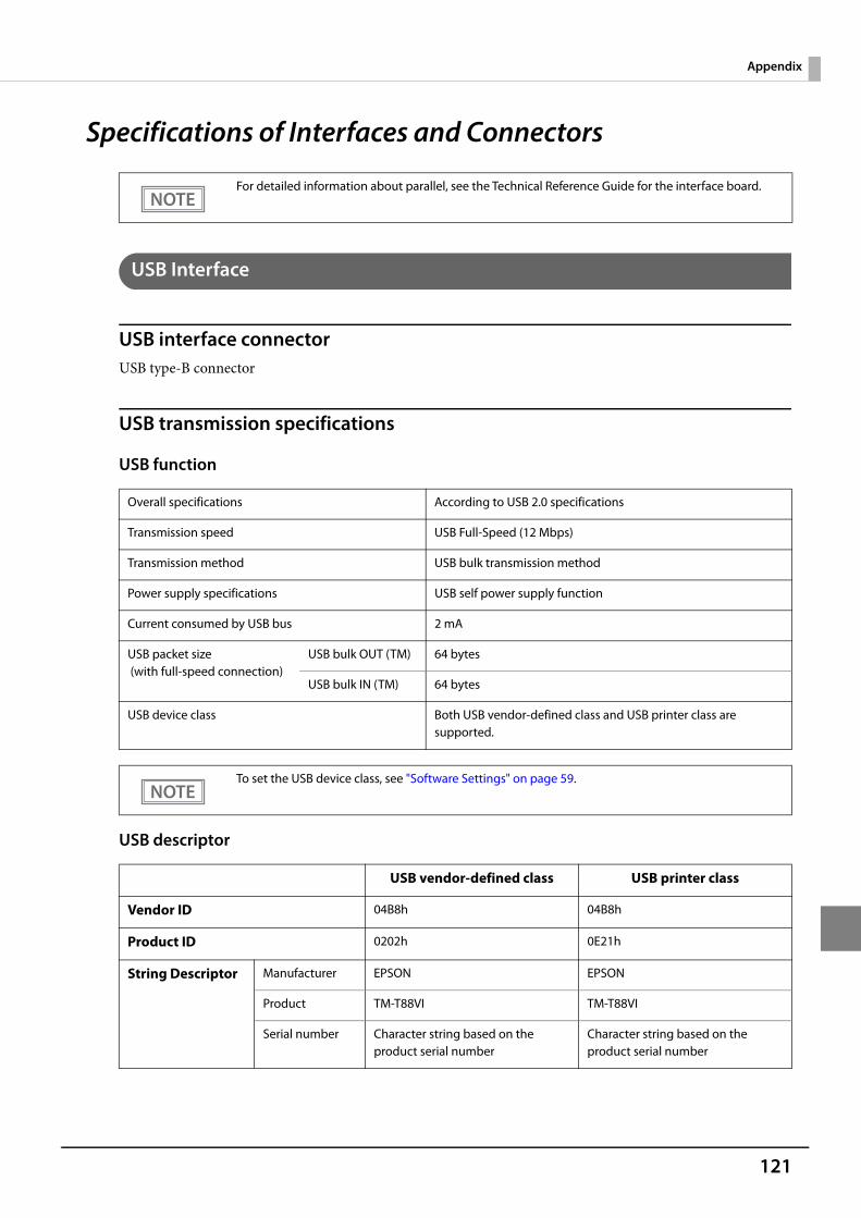
121
Appendix
Specifications of Interfaces and Connectors
USB Interface
USB interface connectorUSB type-B connector
USB transmission specifications
USB function
USB descriptor
For detailed information about parallel, see the Technical Reference Guide for the interface board.
Overall specifications According to USB 2.0 specifications
Transmission speed USB Full-Speed (12 Mbps)
Transmission method USB bulk transmission method
Power supply specifications USB self power supply function
Current consumed by USB bus 2 mA
USB packet size (with full-speed connection)
USB bulk OUT (TM) 64 bytes
USB bulk IN (TM) 64 bytes
USB device class Both USB vendor-defined class and USB printer class are supported.
To set the USB device class, see "Software Settings" on page 59.
USB vendor-defined class USB printer class
Vendor ID 04B8h 04B8h
Product ID 0202h 0E21h
String Descriptor Manufacturer EPSON EPSON
Product TM-T88VI TM-T88VI
Serial number Character string based on the product serial number
Character string based on the product serial number
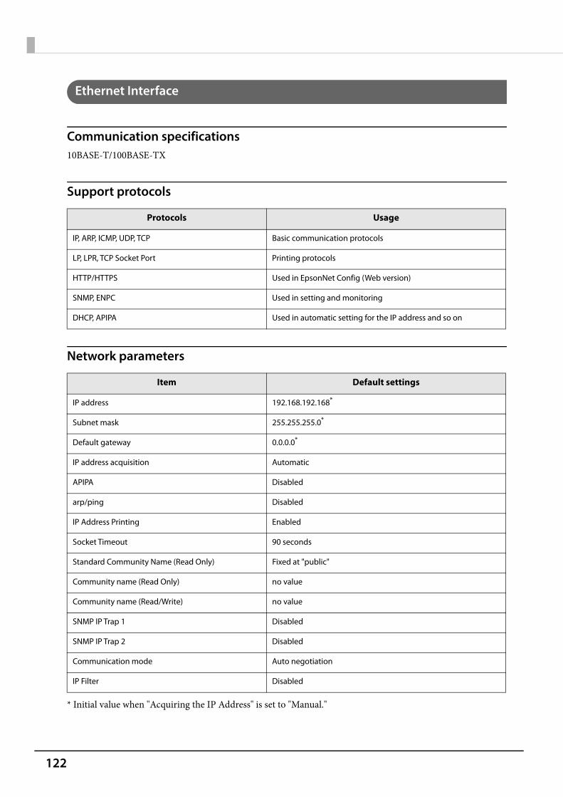
122
Ethernet Interface
Communication specifications10BASE-T/100BASE-TX
Support protocols
Network parameters
* Initial value when "Acquiring the IP Address" is set to "Manual."
Protocols Usage
IP, ARP, ICMP, UDP, TCP Basic communication protocols
LP, LPR, TCP Socket Port Printing protocols
HTTP/HTTPS Used in EpsonNet Config (Web version)
SNMP, ENPC Used in setting and monitoring
DHCP, APIPA Used in automatic setting for the IP address and so on
Item Default settings
IP address 192.168.192.168*
Subnet mask 255.255.255.0*
Default gateway 0.0.0.0*
IP address acquisition Automatic
APIPA Disabled
arp/ping Disabled
IP Address Printing Enabled
Socket Timeout 90 seconds
Standard Community Name (Read Only) Fixed at "public"
Community name (Read Only) no value
Community name (Read/Write) no value
SNMP IP Trap 1 Disabled
SNMP IP Trap 2 Disabled
Communication mode Auto negotiation
IP Filter Disabled
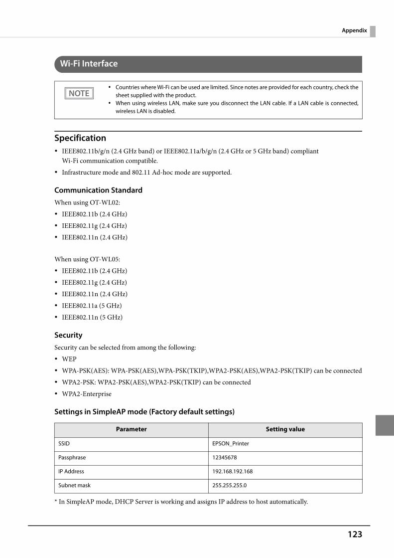
123
Appendix
Wi-Fi Interface
Specification IEEE802.11b/g/n (2.4 GHz band) or IEEE802.11a/b/g/n (2.4 GHz or 5 GHz band) compliant
Wi-Fi communication compatible. Infrastructure mode and 802.11 Ad-hoc mode are supported.
Communication StandardWhen using OT-WL02: IEEE802.11b (2.4 GHz) IEEE802.11g (2.4 GHz) IEEE802.11n (2.4 GHz)
When using OT-WL05: IEEE802.11b (2.4 GHz) IEEE802.11g (2.4 GHz) IEEE802.11n (2.4 GHz) IEEE802.11a (5 GHz) IEEE802.11n (5 GHz)
SecuritySecurity can be selected from among the following: WEP WPA-PSK(AES): WPA-PSK(AES),WPA-PSK(TKIP),WPA2-PSK(AES),WPA2-PSK(TKIP) can be connected WPA2-PSK: WPA2-PSK(AES),WPA2-PSK(TKIP) can be connected WPA2-Enterprise
Settings in SimpleAP mode (Factory default settings)
* In SimpleAP mode, DHCP Server is working and assigns IP address to host automatically.
Countries where Wi-Fi can be used are limited. Since notes are provided for each country, check thesheet supplied with the product.
When using wireless LAN, make sure you disconnect the LAN cable. If a LAN cable is connected,wireless LAN is disabled.
Parameter Setting value
SSID EPSON_Printer
Passphrase 12345678
IP Address 192.168.192.168
Subnet mask 255.255.255.0
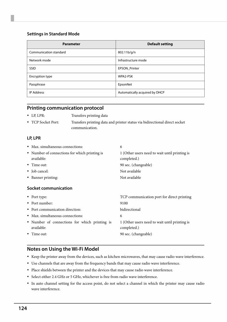
124
Settings in Standard Mode
Printing communication protocol LP, LPR: Transfers printing data TCP Socket Port: Transfers printing data and printer status via bidirectional direct socket
communication.
LP, LPR
Socket communication
Notes on Using the Wi-Fi Model Keep the printer away from the devices, such as kitchen microwaves, that may cause radio wave interference. Use channels that are away from the frequency bands that may cause radio wave interference. Place shields between the printer and the devices that may cause radio wave interference. Select either 2.4 GHz or 5 GHz, whichever is free from radio wave interference. In auto channel setting for the access point, do not select a channel in which the printer may cause radio
wave interference.
Parameter Default setting
Communication standard 802.11b/g/n
Network mode Infrastructure mode
SSID EPSON_Printer
Encryption type WPA2-PSK
Passphrase EpsonNet
IP Address Automatically acquired by DHCP
Max. simultaneous connections: 6 Number of connections for which printing is
available:1 (Other users need to wait until printing is completed.)
Time out: 90 sec. (changeable) Job cancel: Not available Banner printing: Not available
Port type: TCP communication port for direct printing Port number: 9100 Port communication direction: bidirectional Max. simultaneous connections: 6 Number of connections for which printing is
available:1 (Other users need to wait until printing is completed.)
Time out: 90 sec. (changeable)
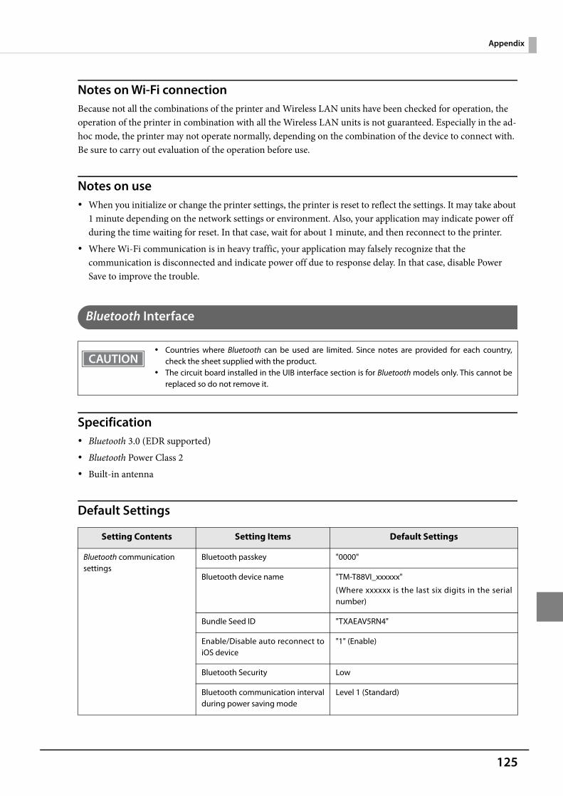
125
Appendix
Notes on Wi-Fi connectionBecause not all the combinations of the printer and Wireless LAN units have been checked for operation, the operation of the printer in combination with all the Wireless LAN units is not guaranteed. Especially in the ad-hoc mode, the printer may not operate normally, depending on the combination of the device to connect with. Be sure to carry out evaluation of the operation before use.
Notes on use When you initialize or change the printer settings, the printer is reset to reflect the settings. It may take about
1 minute depending on the network settings or environment. Also, your application may indicate power off during the time waiting for reset. In that case, wait for about 1 minute, and then reconnect to the printer.
Where Wi-Fi communication is in heavy traffic, your application may falsely recognize that the communication is disconnected and indicate power off due to response delay. In that case, disable Power Save to improve the trouble.
Bluetooth Interface
Specification Bluetooth 3.0 (EDR supported) Bluetooth Power Class 2 Built-in antenna
Default Settings
Countries where Bluetooth can be used are limited. Since notes are provided for each country,check the sheet supplied with the product.
The circuit board installed in the UIB interface section is for Bluetooth models only. This cannot bereplaced so do not remove it.
Setting Contents Setting Items Default Settings
Bluetooth communication settings
Bluetooth passkey "0000"
Bluetooth device name "TM-T88VI_xxxxxx"
(Where xxxxxx is the last six digits in the serialnumber)
Bundle Seed ID "TXAEAV5RN4"
Enable/Disable auto reconnect toiOS device
"1" (Enable)
Bluetooth Security Low
Bluetooth communication intervalduring power saving mode
Level 1 (Standard)
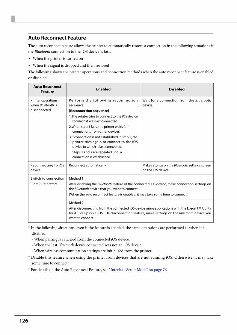
126
Auto Reconnect FeatureThe auto reconnect feature allows the printer to automatically restore a connection in the following situations ifthe Bluetooth connection to the iOS device is lost. When the printer is turned on When the signal is dropped and then restoredThe following shows the printer operations and connection methods when the auto reconnect feature is enabledor disabled.
* In the following situations, even if the feature is enabled, the same operations are performed as when it is disabled.- When pairing is canceled from the connected iOS device.- When the last Bluetooth device connected was not an iOS device.- When wireless communication settings are initialized from the printer.
* Disable this feature when using the printer from devices that are not running iOS. Otherwise, it may takesome time to connect.
* For details on the Auto Reconnect Feature, see "Interface Setup Mode" on page 76.
Auto ReconnectFeature
Enabled Disabled
Printer operations when Bluetooth is disconnected
Pe r f o r m t h e f o l l o w i n g r e c o n n e c t i o nsequence.
[Reconnection sequence]
1.The printer tries to connect to the iOS deviceto which it was last connected.
2.When step 1 fails, the printer waits for connections from other devices.
3.If connection is not established in step 2, theprinter tries again to connect to the iOSdevice to which it last connected.
Steps 1 and 2 are repeated until a connection is established.
Wait for a connection from the Bluetoothdevice.
Reconnecting to iOSdevice
Reconnect automatically. Make settings on the Bluetooth settings screenon the iOS device.
Switch to connectionfrom other device
Method 1:
After disabling the Bluetooth feature of the connected iOS device, make connection settings onthe Bluetooth device that you want to connect.
(When the auto reconnect feature is enabled, it may take some time to connect.)
Method 2:
After disconnecting from the connected iOS device using applications with the Epson TM Utilityfor iOS or Epson ePOS SDK disconnection feature, make settings on the Bluetooth device youwant to connect.
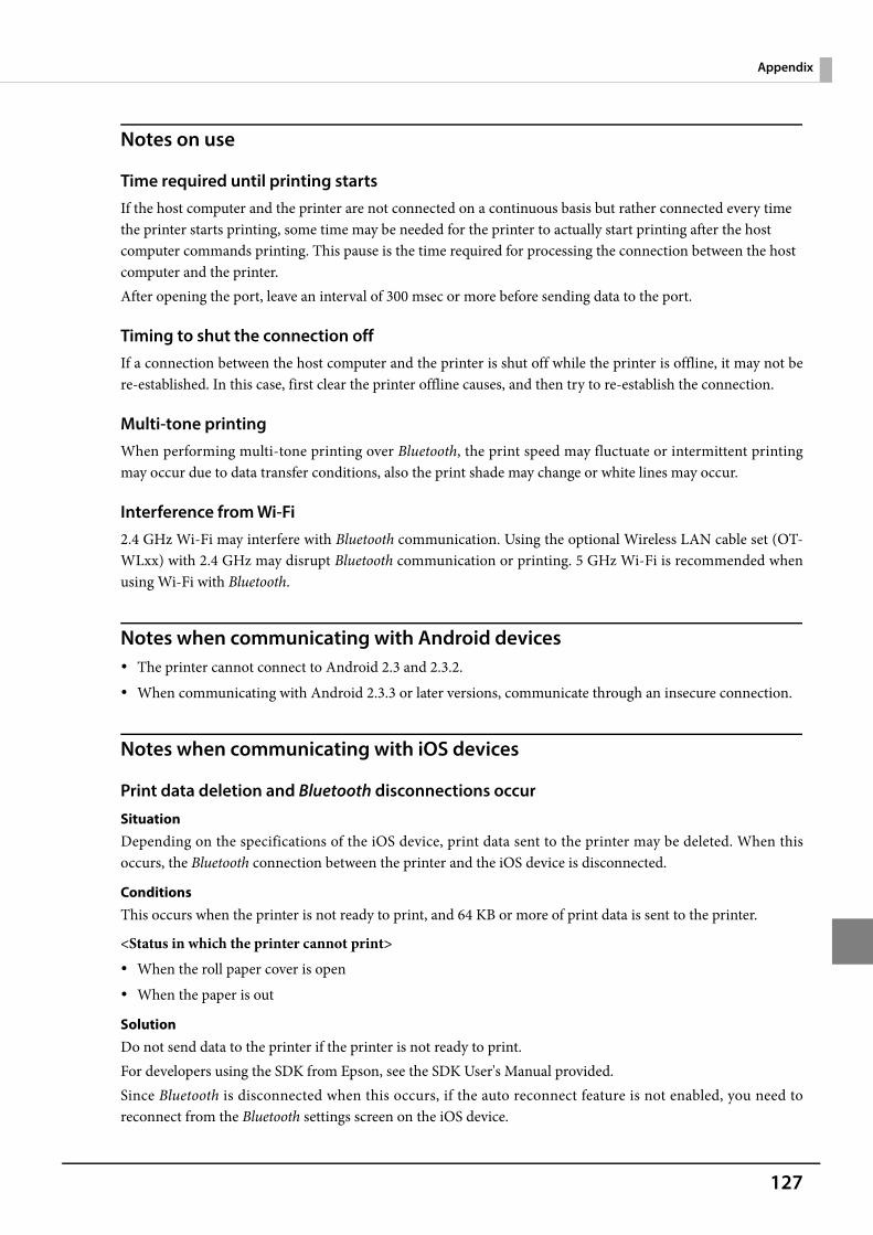
127
Appendix
Notes on use
Time required until printing startsIf the host computer and the printer are not connected on a continuous basis but rather connected every time the printer starts printing, some time may be needed for the printer to actually start printing after the host computer commands printing. This pause is the time required for processing the connection between the host computer and the printer.After opening the port, leave an interval of 300 msec or more before sending data to the port.
Timing to shut the connection offIf a connection between the host computer and the printer is shut off while the printer is offline, it may not bere-established. In this case, first clear the printer offline causes, and then try to re-establish the connection.
Multi-tone printingWhen performing multi-tone printing over Bluetooth, the print speed may fluctuate or intermittent printingmay occur due to data transfer conditions, also the print shade may change or white lines may occur.
Interference from Wi-Fi2.4 GHz Wi-Fi may interfere with Bluetooth communication. Using the optional Wireless LAN cable set (OT-WLxx) with 2.4 GHz may disrupt Bluetooth communication or printing. 5 GHz Wi-Fi is recommended whenusing Wi-Fi with Bluetooth.
Notes when communicating with Android devices The printer cannot connect to Android 2.3 and 2.3.2. When communicating with Android 2.3.3 or later versions, communicate through an insecure connection.
Notes when communicating with iOS devices
Print data deletion and Bluetooth disconnections occur
SituationDepending on the specifications of the iOS device, print data sent to the printer may be deleted. When thisoccurs, the Bluetooth connection between the printer and the iOS device is disconnected.
ConditionsThis occurs when the printer is not ready to print, and 64 KB or more of print data is sent to the printer.
<Status in which the printer cannot print> When the roll paper cover is open When the paper is out
SolutionDo not send data to the printer if the printer is not ready to print.For developers using the SDK from Epson, see the SDK User's Manual provided.Since Bluetooth is disconnected when this occurs, if the auto reconnect feature is not enabled, you need toreconnect from the Bluetooth settings screen on the iOS device.
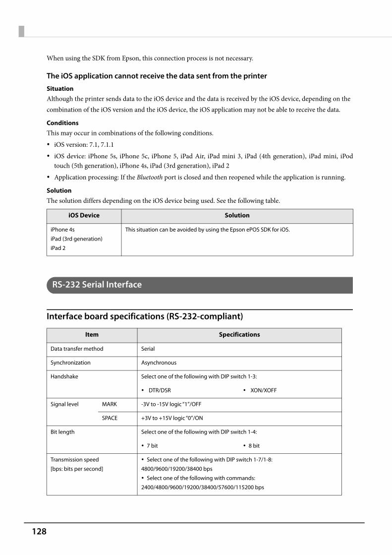
128
When using the SDK from Epson, this connection process is not necessary.
The iOS application cannot receive the data sent from the printer
SituationAlthough the printer sends data to the iOS device and the data is received by the iOS device, depending on thecombination of the iOS version and the iOS device, the iOS application may not be able to receive the data.
ConditionsThis may occur in combinations of the following conditions. iOS version: 7.1, 7.1.1 iOS device: iPhone 5s, iPhone 5c, iPhone 5, iPad Air, iPad mini 3, iPad (4th generation), iPad mini, iPod
touch (5th generation), iPhone 4s, iPad (3rd generation), iPad 2 Application processing: If the Bluetooth port is closed and then reopened while the application is running.
SolutionThe solution differs depending on the iOS device being used. See the following table.
RS-232 Serial Interface
Interface board specifications (RS-232-compliant)
iOS Device Solution
iPhone 4s
iPad (3rd generation)
iPad 2
This situation can be avoided by using the Epson ePOS SDK for iOS.
Item Specifications
Data transfer method Serial
Synchronization Asynchronous
Handshake Select one of the following with DIP switch 1-3:
DTR/DSR XON/XOFF
Signal level MARK -3V to -15V logic “1”/OFF
SPACE +3V to +15V logic “0”/ON
Bit length Select one of the following with DIP switch 1-4:
7 bit 8 bit
Transmission speed
[bps: bits per second]
Select one of the following with DIP switch 1-7/1-8:
4800/9600/19200/38400 bps
Select one of the following with commands:
2400/4800/9600/19200/38400/57600/115200 bps
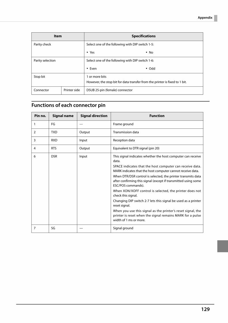
129
Appendix
Functions of each connector pin
Parity check Select one of the following with DIP switch 1-5:
Yes No
Parity selection Select one of the following with DIP switch 1-6:
Even Odd
Stop bit 1 or more bits
However, the stop bit for data transfer from the printer is fixed to 1 bit.
Connector Printer side DSUB 25-pin (female) connector
Pin no. Signal name Signal direction Function
1 FG — Frame ground
2 TXD Output Transmission data
3 RXD Input Reception data
4 RTS Output Equivalent to DTR signal (pin 20)
6 DSR Input This signal indicates whether the host computer can receivedata.
SPACE indicates that the host computer can receive data.MARK indicates that the host computer cannot receive data.
When DTR/DSR control is selected, the printer transmits dataafter confirming this signal (except if transmitted using someESC/POS commands).
When XON/XOFF control is selected, the printer does notcheck this signal.
Changing DIP switch 2-7 lets this signal be used as a printerreset signal.
When you use this signal as the printer’s reset signal, theprinter is reset when the signal remains MARK for a pulsewidth of 1 ms or more.
7 SG — Signal ground
Item Specifications

130
XON/XOFFWhen XON/XOFF control is selected, the printer transmits the XON or XOFF signals as follows. The transmission timing of XON/XOFF differs, depending on the setting of DIP switch 2-1.
20 DTR Output 1) When DTR/DSR control is selected, this signal indicateswhether the printer is BUSY.
SPACE status
Indicates that the printer is ready to receive data.
MARK status
Indicates that the printer is BUSY. Set BUSY conditions withDIP switch 2-1.
2) When XON/XOFF control is selected, the signal indicatesthat the printer is properly connected and ready to receivedata from the host. The signal is always SPACE, except in thefollowing cases:
During the period from when power is turned on to whenthe printer is ready to receive data.
During the self-test.
25 INT Input Changing DIP switch 2-8 enables this signal to be used as areset signal for the printer. The printer is reset if the signalremains at SPACE for a pulse width of 1 ms or more.
Signal Printer statusDIP switch 2-1
1 (ON) 0 (OFF)
XON 1) When the printer goes online after turning on the power (or reset usingthe interface)
Transmit Transmit
2) When the receive buffer is released from the buffer full state Transmit Transmit
3) When the printer switches from offline to online — Transmit
4) When the printer recovers from an error using some ESC/POS commands
— Transmit
XOFF 5) When the receive buffer becomes full Transmit Transmit
6) When the printer switches from online to offline — Transmit
Pin no. Signal name Signal direction Function
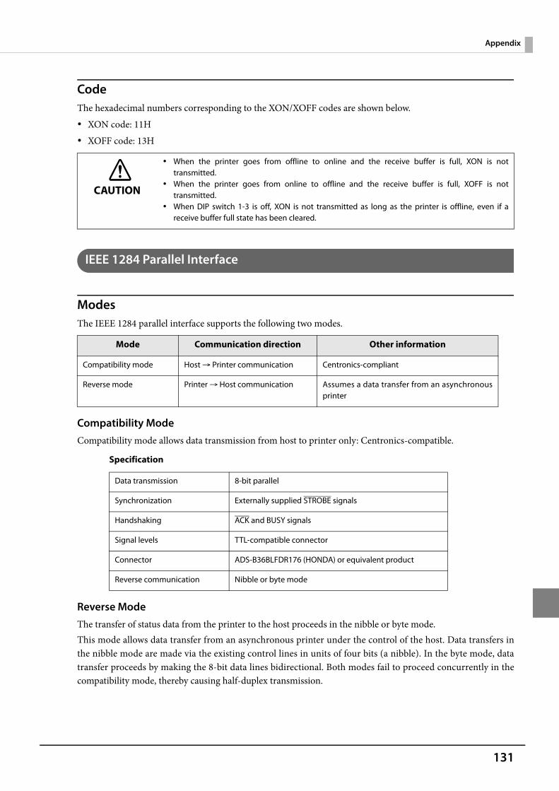
131
Appendix
CodeThe hexadecimal numbers corresponding to the XON/XOFF codes are shown below. XON code: 11H XOFF code: 13H
IEEE 1284 Parallel Interface
ModesThe IEEE 1284 parallel interface supports the following two modes.
Compatibility ModeCompatibility mode allows data transmission from host to printer only: Centronics-compatible.
Specification
Reverse ModeThe transfer of status data from the printer to the host proceeds in the nibble or byte mode.This mode allows data transfer from an asynchronous printer under the control of the host. Data transfers inthe nibble mode are made via the existing control lines in units of four bits (a nibble). In the byte mode, datatransfer proceeds by making the 8-bit data lines bidirectional. Both modes fail to proceed concurrently in thecompatibility mode, thereby causing half-duplex transmission.
CAUTION
When the printer goes from offline to online and the receive buffer is full, XON is nottransmitted.
When the printer goes from online to offline and the receive buffer is full, XOFF is nottransmitted.
When DIP switch 1-3 is off, XON is not transmitted as long as the printer is offline, even if areceive buffer full state has been cleared.
Mode Communication direction Other information
Compatibility mode Host Printer communication Centronics-compliant
Reverse mode Printer Host communication Assumes a data transfer from an asynchronousprinter
Data transmission 8-bit parallel
Synchronization Externally supplied STROBE signals
Handshaking ACK and BUSY signals
Signal levels TTL-compatible connector
Connector ADS-B36BLFDR176 (HONDA) or equivalent product
Reverse communication Nibble or byte mode

132
Interface signals
Pin Source Compatibility Mode Nibble Mode Byte Mode
1 Host Strobe HostClk HostClk
2 Host/Ptr Data0 (LSB) Data0 (LSB) Data0 (LSB)
3 Host/Ptr Data1 Data1 Data1
4 Host/Ptr Data2 Data2 Data2
5 Host/Ptr Data3 Data3 Data3
6 Host/Ptr Data4 Data4 Data4
7 Host/Ptr Data5 Data5 Data5
8 Host/Ptr Data6 Data6 Data6
9 Host/Ptr Data7 (MSB) Data7 (MSB) Data7 (MSB)
10 Printer Ack PtrClk PtrClk
11 Printer Busy PtrBusy/Data3,7 PtrBusy
12 Printer Perror AckDataReq/Data2,6 AckDataReq
13 Printer Select Xflag/Data1,5 Xflag
14 Host AutoFd HostBusy k HostBusy
15 NC ND ND
16 GND GND GND
17 FG FG FG
18 Printer Logic-H Logic-H Logic-H
19 GND GND GND
20 GND GND GND
21 GND GND GND
22 GND GND GND
23 GND GND GND
24 GND GND GND
25 GND GND GND
26 GND GND GND
27 GND GND GND
28 GND GND GND
29 GND GND GND
30 GND GND GND
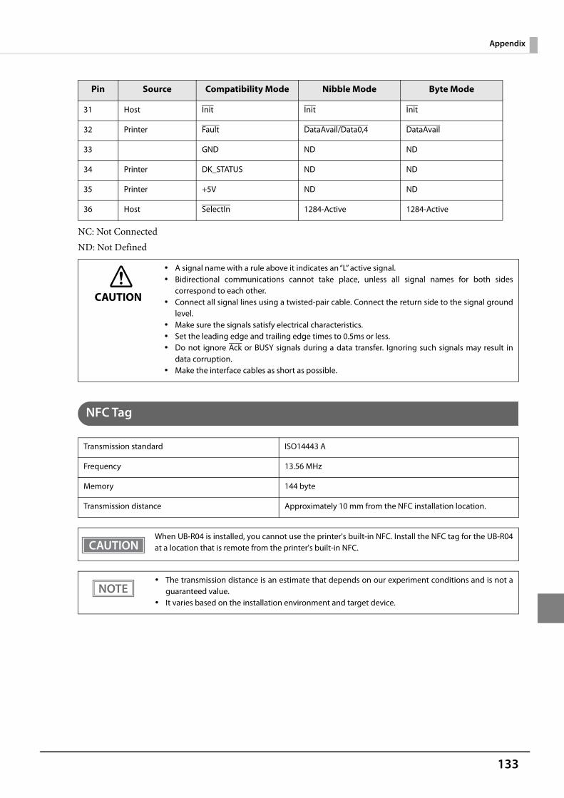
133
Appendix
NC: Not ConnectedND: Not Defined
NFC Tag
31 Host Init Init Init
32 Printer Fault DataAvail/Data0,4 DataAvail
33 GND ND ND
34 Printer DK_STATUS ND ND
35 Printer +5V ND ND
36 Host SelectIn 1284-Active 1284-Active
CAUTION
A signal name with a rule above it indicates an “L” active signal. Bidirectional communications cannot take place, unless all signal names for both sides
correspond to each other. Connect all signal lines using a twisted-pair cable. Connect the return side to the signal ground
level. Make sure the signals satisfy electrical characteristics. Set the leading edge and trailing edge times to 0.5ms or less. Do not ignore Ack or BUSY signals during a data transfer. Ignoring such signals may result in
data corruption. Make the interface cables as short as possible.
Transmission standard ISO14443 A
Frequency 13.56 MHz
Memory 144 byte
Transmission distance Approximately 10 mm from the NFC installation location.
When UB-R04 is installed, you cannot use the printer's built-in NFC. Install the NFC tag for the UB-R04at a location that is remote from the printer's built-in NFC.
The transmission distance is an estimate that depends on our experiment conditions and is not aguaranteed value.
It varies based on the installation environment and target device.
Pin Source Compatibility Mode Nibble Mode Byte Mode
134
Bluetooth Low Energy Technology Advertising
Introduction
When you connect the BT820 from Lairedtec to the USB A connector on the TM-T88VI and turn it on, the Bluetooth low energy technology Advertising Packet is transmitted. By default, the TM-T88VI transmits the packet according to the iBeacon Format from Apple. You can also change the data that is transmitted by following the steps in "Changing the Bluetooth Low Energy Technology Advertising Packet" on page 135.
Glossary:
Dongle specifications
Manufacturer: Laird TechModel name: BT-820
For setting methods and settings, see the TM-T88VI Utility User's Manual.
Procedure
When turning on the TM-T88VI, the Bluetooth adapter connected to the USB Type A connector is enabled.If you install the Bluetooth adapter after turning on the printer, this is not enabled.
Bluetooth Low Energy Technology Advertising Packet FormatIn the TM-T88VI, the iBeacon format is used by default for the Bluetooth low energy technology AdvertisingPacket.The UUID for the T88VI is "fac1ba2f-61a2-4d83-9a8c-60087c232569".The user can edit the following specifications in the iBeacon format: UUID, Major number, Minor number, andMeasured Power.
Term Description
Bluetooth Low Energy Technology Advertising The name of this function.
Bluetooth Low Energy Technology Advertising Packet
The data sent by this function from the printer.
Bluetooth adapter The BT820 from Lairedtec
A USB dongle to connect to the USB Type A connector.
iBeacon The format stipulated by Apple for Bluetooth low energy technology Advertising Packets
When using the default settings for the TM-T88VI (Bluetooth adapter installed in the printer and the printer is on), the Bluetooth low energy technology Advertising Packet is transmitted in iBeacon format.
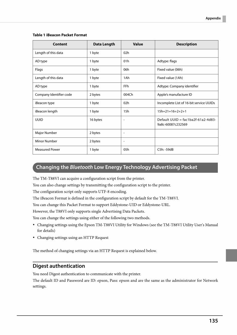
135
Appendix
Table 1 iBeacon Packet Format
Changing the Bluetooth Low Energy Technology Advertising Packet
The TM-T88VI can acquire a configuration script from the printer.You can also change settings by transmitting the configuration script to the printer.The configuration script only supports UTF-8 encoding.The iBeacon Format is defined in the configuration script by default for the TM-T88VI.You can change this Packet Format to support Eddystone-UID or Eddystone-URL.However, the T88VI only supports single Advertising Data Packets.You can change the settings using either of the following two methods. Changing settings using the Epson TM-T88VI Utility for Windows (see the TM-T88VI Utility User's Manual
for details) Changing settings using an HTTP Request
The method of changing settings via an HTTP Request is explained below.
Digest authenticationYou need Digest authentication to communicate with the printer.The default ID and Password are ID: epson, Pass: epson and are the same as the administrator for Networksettings.
Content Data Length Value Description
Length of this data 1 byte 02h
AD type 1 byte 01h Adtype: flags
Flags 1 byte 06h Fixed value (06h)
Length of this data 1 byte 1Ah Fixed value (1Ah)
AD type 1 byte FFh Adtype: Company identifier
Company Identifier code 2 bytes 004Ch Apple’s manufacture ID
iBeacon type 1 byte 02h Incomplete List of 16-bit service UUIDs
iBeacon length 1 byte 15h 15h=21=16+2+2+1
UUID 16 bytes - Default UUID = fac1ba2f-61a2-4d83-9a8c-60087c232569
Major Number 2 bytes -
Minor Number 2 bytes -
Measured Power 1 byte 05h C5h: -59dB
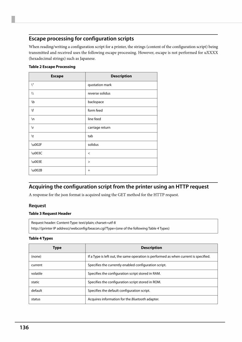
136
Escape processing for configuration scriptsWhen reading/writing a configuration script for a printer, the strings (content of the configuration script) beingtransmitted and received uses the following escape processing. However, escape is not performed for uXXXX(hexadecimal strings) such as Japanese.
Table 2 Escape Processing
Acquiring the configuration script from the printer using an HTTP requestA response for the json format is acquired using the GET method for the HTTP request.
Request
Table 3 Request Header
Table 4 Types
Escape Description
\” quotation mark
\\ reverse solidus
\b backspace
\f form feed
\n line feed
\r carriage return
\t tab
\u002F solidus
\u003C <
\u003E >
\u002B +
Request header: Content-Type: text/plain; charset=utf-8
http://(printer IP address)/webconfig/beacon.cgi?Type=(one of the following Table 4 Types)
Type Description
(none) If a Type is left out, the same operation is performed as when current is specified.
current Specifies the currently enabled configuration script.
volatile Specifies the configuration script stored in RAM.
static Specifies the configuration script stored in ROM.
default Specifies the default configuration script.
status Acquires information for the Bluetooth adapter.
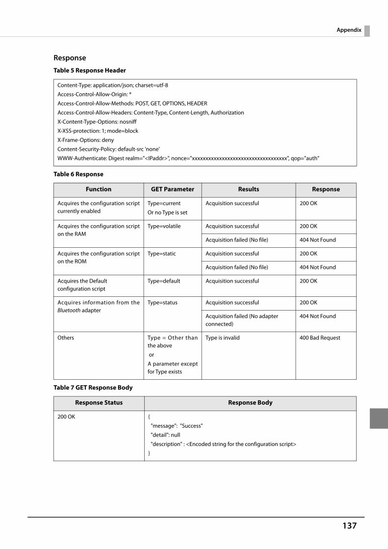
137
Appendix
Response
Table 5 Response Header
Table 6 Response
Table 7 GET Response Body
Content-Type: application/json; charset=utf-8
Access-Control-Allow-Origin: *
Access-Control-Allow-Methods: POST, GET, OPTIONS, HEADER
Access-Control-Allow-Headers: Content-Type, Content-Length, Authorization
X-Content-Type-Options: nosniff
X-XSS-protection: 1; mode=block
X-Frame-Options: deny
Content-Security-Policy: default-src 'none'
WWW-Authenticate: Digest realm="<IPaddr>", nonce="xxxxxxxxxxxxxxxxxxxxxxxxxxxxxxxxxxx", qop="auth"
Function GET Parameter Results Response
Acquires the configuration scriptcurrently enabled
Type=current
Or no Type is set
Acquisition successful 200 OK
Acquires the configuration scripton the RAM
Type=volatile Acquisition successful 200 OK
Acquisition failed (No file) 404 Not Found
Acquires the configuration scripton the ROM
Type=static Acquisition successful 200 OK
Acquisition failed (No file) 404 Not Found
Acquires the Default configuration script
Type=default Acquisition successful 200 OK
Acquires information from theBluetooth adapter
Type=status Acquisition successful 200 OK
Acquisition failed (No adapter connected)
404 Not Found
Others Type = Other thanthe above
or
A parameter exceptfor Type exists
Type is invalid 400 Bad Request
Response Status Response Body
200 OK {
"message": "Success"
"detail": null
"description" : <Encoded string for the configuration script>
}
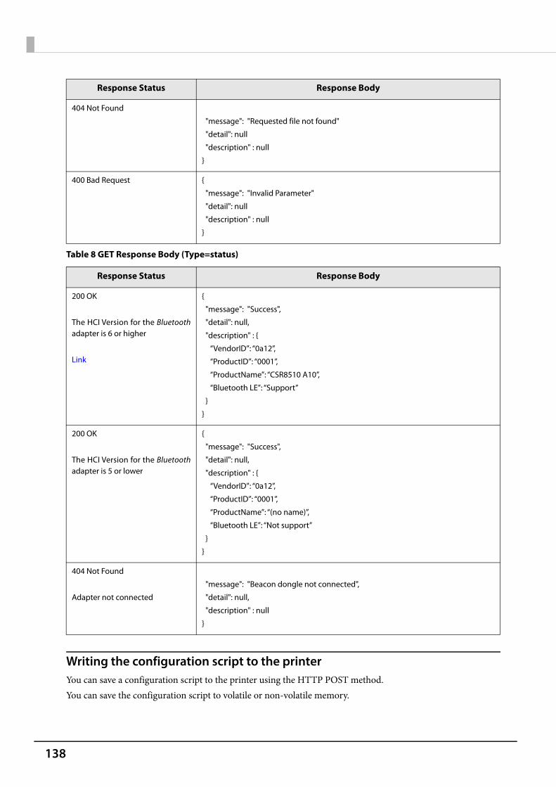
138
Table 8 GET Response Body (Type=status)
Writing the configuration script to the printerYou can save a configuration script to the printer using the HTTP POST method.You can save the configuration script to volatile or non-volatile memory.
404 Not Found
"message": "Requested file not found"
"detail": null
"description" : null
}
400 Bad Request {
"message": "Invalid Parameter"
"detail": null
"description" : null
}
Response Status Response Body
200 OK
The HCI Version for the Bluetoothadapter is 6 or higher
Link
{
"message": "Success",
"detail": null,
"description" : {
“VendorID”: “0a12”,
“ProductID”: “0001”,
“ProductName”: “CSR8510 A10”,
“Bluetooth LE”: “Support”
}
}
200 OK
The HCI Version for the Bluetoothadapter is 5 or lower
{
"message": "Success",
"detail": null,
"description" : {
“VendorID”: “0a12”,
“ProductID”: “0001”,
“ProductName”: “(no name)”,
“Bluetooth LE”: “Not support”
}
}
404 Not Found
Adapter not connected
"message": "Beacon dongle not connected",
"detail": null,
"description" : null
}
Response Status Response Body
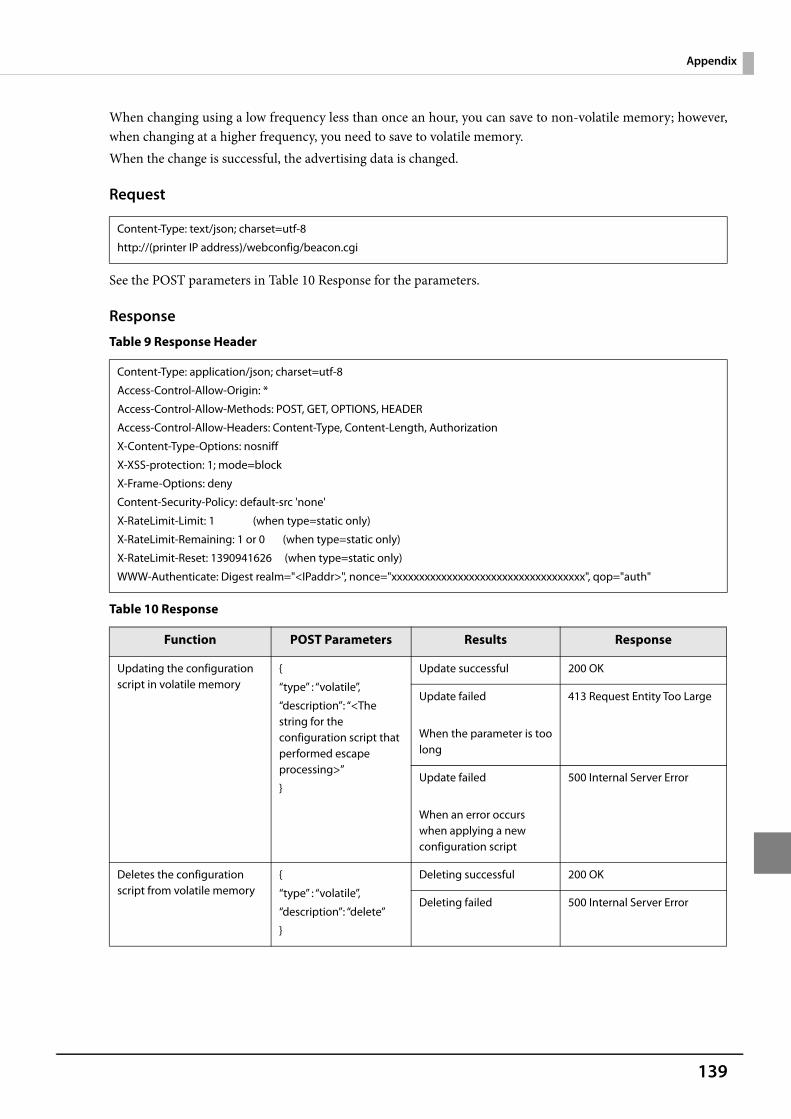
139
Appendix
When changing using a low frequency less than once an hour, you can save to non-volatile memory; however,when changing at a higher frequency, you need to save to volatile memory.When the change is successful, the advertising data is changed.
Request
See the POST parameters in Table 10 Response for the parameters.
Response
Table 9 Response Header
Table 10 Response
Content-Type: text/json; charset=utf-8
http://(printer IP address)/webconfig/beacon.cgi
Content-Type: application/json; charset=utf-8
Access-Control-Allow-Origin: *
Access-Control-Allow-Methods: POST, GET, OPTIONS, HEADER
Access-Control-Allow-Headers: Content-Type, Content-Length, Authorization
X-Content-Type-Options: nosniff
X-XSS-protection: 1; mode=block
X-Frame-Options: deny
Content-Security-Policy: default-src 'none'
X-RateLimit-Limit: 1 (when type=static only)
X-RateLimit-Remaining: 1 or 0 (when type=static only)
X-RateLimit-Reset: 1390941626 (when type=static only)
WWW-Authenticate: Digest realm="<IPaddr>", nonce="xxxxxxxxxxxxxxxxxxxxxxxxxxxxxxxxxxx", qop="auth"
Function POST Parameters Results Response
Updating the configuration script in volatile memory
{
“type” : “volatile”,
“description”: “<The string for the configuration script that performed escape processing>”
}
Update successful 200 OK
Update failed
When the parameter is toolong
413 Request Entity Too Large
Update failed
When an error occurs when applying a new configuration script
500 Internal Server Error
Deletes the configuration script from volatile memory
{
“type” : “volatile”,
“description”: “delete”
}
Deleting successful 200 OK
Deleting failed 500 Internal Server Error
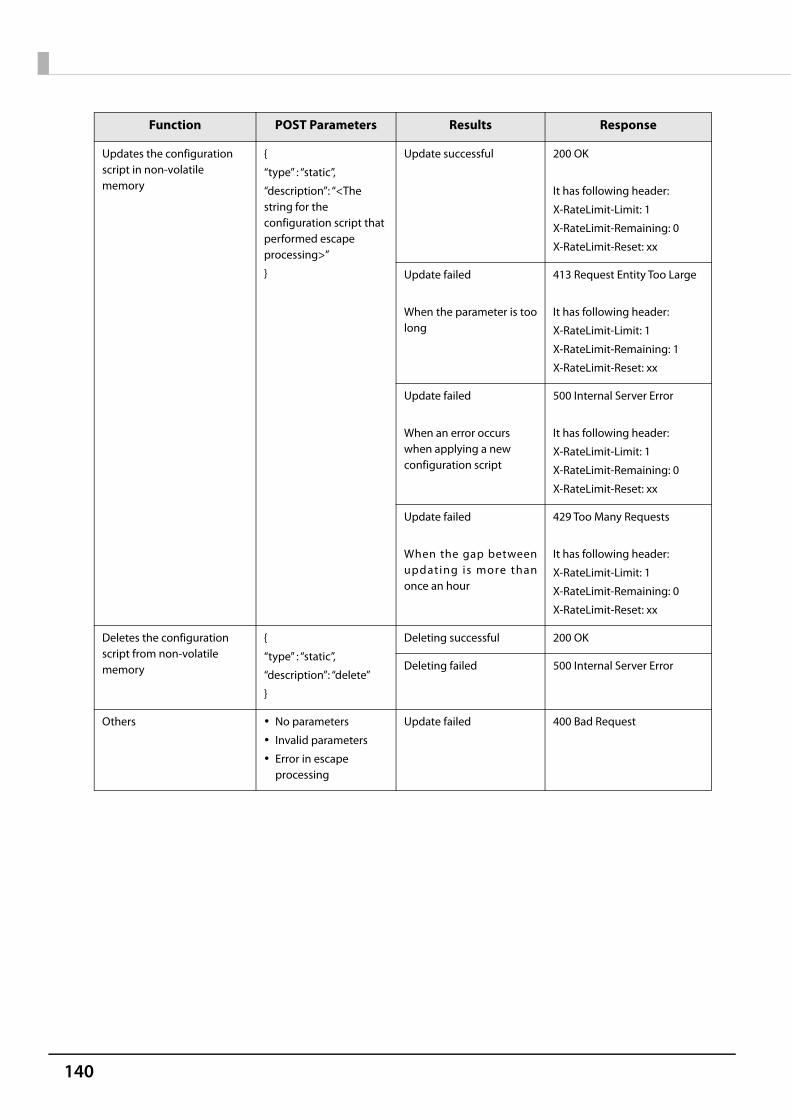
140
Updates the configuration script in non-volatile memory
{
“type” : “static”,
“description”: “<The string for the configuration script that performed escape processing>”
}
Update successful 200 OK
It has following header:
X-RateLimit-Limit: 1
X-RateLimit-Remaining: 0
X-RateLimit-Reset: xx
Update failed
When the parameter is toolong
413 Request Entity Too Large
It has following header:
X-RateLimit-Limit: 1
X-RateLimit-Remaining: 1
X-RateLimit-Reset: xx
Update failed
When an error occurs when applying a new configuration script
500 Internal Server Error
It has following header:
X-RateLimit-Limit: 1
X-RateLimit-Remaining: 0
X-RateLimit-Reset: xx
Update failed
When the gap betweenupdating is more thanonce an hour
429 Too Many Requests
It has following header:
X-RateLimit-Limit: 1
X-RateLimit-Remaining: 0
X-RateLimit-Reset: xx
Deletes the configuration script from non-volatile memory
{
“type” : “static”,
“description”: “delete”
}
Deleting successful 200 OK
Deleting failed 500 Internal Server Error
Others No parameters
Invalid parameters
Error in escape processing
Update failed 400 Bad Request
Function POST Parameters Results Response

141
Appendix
Table 11 POST Response Body
Table 12 400 Bad Request Details
Response Status Body
200 OK {
"message": "Success",
"detail": null,
"description" : < The string for the configuration script that performed escape processing >
}
400 Bad Request {
"message": "Invalid Parameter",
"detail": “***”, (see Table 12)
"description" : null
}
413 Request Entity Too Large {
"message": "Request Entity Too Large",
"detail": null,
"description" : null
}
429 Too Many Requests {
"message": "You sent too many requests in a given amount of time.",
"detail": null,
"description": null
}
500 Internal Server Error {
"message": "Failed to update settings",
"detail": “***”, (see Table 13)
"description" : null
}
Case Body
The correct escape processing isn o t p e r fo r m e d a t t h e p o i n tescape processing is needed
{
"message": "Invalid Parameter",
"detail": ”Special characters must be escaped”,
"description" : null
}
An undefined Type parameter hasbeen specified
{
"message": "Invalid Parameter",
"detail": “A parameter ‘type’ is invalid”,
"description" : null
}
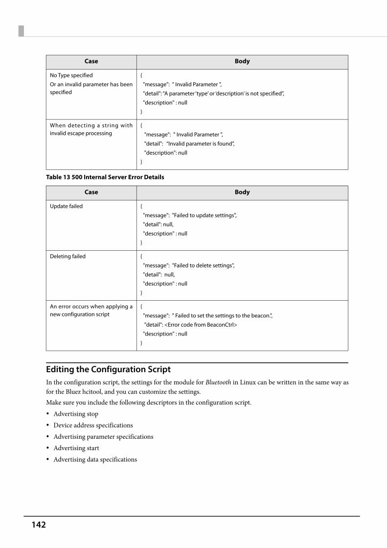
142
Table 13 500 Internal Server Error Details
Editing the Configuration ScriptIn the configuration script, the settings for the module for Bluetooth in Linux can be written in the same way asfor the Bluez hcitool, and you can customize the settings.Make sure you include the following descriptors in the configuration script. Advertising stop Device address specifications Advertising parameter specifications Advertising start Advertising data specifications
No Type specified
Or an invalid parameter has beenspecified
{
"message": " Invalid Parameter ",
"detail": “A parameter ‘type’ or ‘description’ is not specified”,
"description" : null
}
When detecting a string withinvalid escape processing
{
"message": " Invalid Parameter ",
"detail": “Invalid parameter is found”,
"description": null
}
Case Body
Update failed {
"message": "Failed to update settings",
"detail": null,
"description" : null
}
Deleting failed {
"message": "Failed to delete settings",
"detail": null,
"description" : null
}
An error occurs when applying anew configuration script
{
"message": " Failed to set the settings to the beacon.",
"detail": <Error code from BeaconCtrl>
"description" : null
}
Case Body
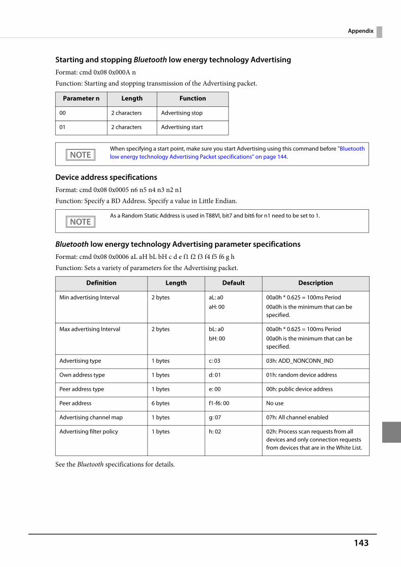
143
Appendix
Starting and stopping Bluetooth low energy technology AdvertisingFormat: cmd 0x08 0x000A nFunction: Starting and stopping transmission of the Advertising packet.
Device address specificationsFormat: cmd 0x08 0x0005 n6 n5 n4 n3 n2 n1Function: Specify a BD Address. Specify a value in Little Endian.
Bluetooth low energy technology Advertising parameter specificationsFormat: cmd 0x08 0x0006 aL aH bL bH c d e f1 f2 f3 f4 f5 f6 g hFunction: Sets a variety of parameters for the Advertising packet.
See the Bluetooth specifications for details.
Parameter n Length Function
00 2 characters Advertising stop
01 2 characters Advertising start
When specifying a start point, make sure you start Advertising using this command before "Bluetoothlow energy technology Advertising Packet specifications" on page 144.
As a Random Static Address is used in T88VI, bit7 and bit6 for n1 need to be set to 1.
Definition Length Default Description
Min advertising Interval 2 bytes aL: a0
aH: 00
00a0h * 0.625 = 100ms Period
00a0h is the minimum that can be specified.
Max advertising Interval 2 bytes bL: a0
bH: 00
00a0h * 0.625 = 100ms Period
00a0h is the minimum that can be specified.
Advertising type 1 bytes c: 03 03h: ADD_NONCONN_IND
Own address type 1 bytes d: 01 01h: random device address
Peer address type 1 bytes e: 00 00h: public device address
Peer address 6 bytes f1-f6: 00 No use
Advertising channel map 1 bytes g: 07 07h: All channel enabled
Advertising filter policy 1 bytes h: 02 02h: Process scan requests from all devices and only connection requests from devices that are in the White List.
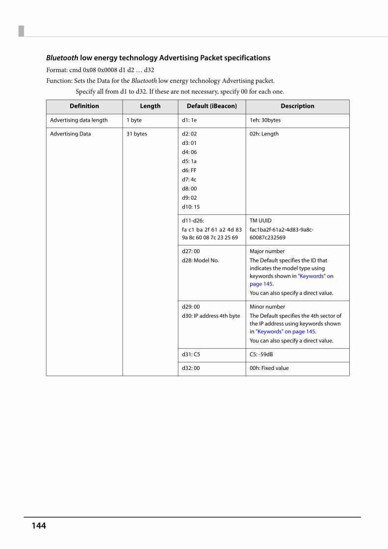
144
Bluetooth low energy technology Advertising Packet specificationsFormat: cmd 0x08 0x0008 d1 d2 … d32Function: Sets the Data for the Bluetooth low energy technology Advertising packet.
Specify all from d1 to d32. If these are not necessary, specify 00 for each one.
Definition Length Default (iBeacon) Description
Advertising data length 1 byte d1: 1e 1eh: 30bytes
Advertising Data 31 bytes d2: 02
d3: 01
d4: 06
d5: 1a
d6: FF
d7: 4c
d8: 00
d9: 02
d10: 15
02h: Length
d11-d26:
fa c1 ba 2f 61 a2 4d 839a 8c 60 08 7c 23 25 69
TM UUID
fac1ba2f-61a2-4d83-9a8c-60087c232569
d27: 00
d28: Model No.
Major number
The Default specifies the ID that indicates the model type using keywords shown in "Keywords" on page 145.
You can also specify a direct value.
d29: 00
d30: IP address 4th byte
Minor number
The Default specifies the 4th sector of the IP address using keywords shown in "Keywords" on page 145.
You can also specify a direct value.
d31: C5 C5: -59dB
d32: 00 00h: Fixed value

145
Appendix
KeywordsYou can specify the following keywords when describing the script.
Reserve String Length Content Example
$SERIAL_ADDR 6 bytes Address that uses 1 for the MSB2bit in the last 6 digits of the printer's serial number.
When the Serial No. is ABCD123456, the Address uses 1 for the MSB2bits for the leading 1 byte in the last 6 digits.
F1:32:33:34:35:36
is generated and replaced with a string using 36 35 34 33 32 F1 sorted in Little endian.
$RANDOM_ADDR 6 bytes Address in which the printer generates a random 6 byte number, and 1 is for the MSB2bit of the leading 1 byte.
Generates a random 6 byte number in the printer and replaces it with a string that sorts the Address using 1 for the MSB2bits for the leading 1byte in Little endian.
$IPn 1 byte Value for #n in the printer's IP address.
When the IP address is 192.168.192.168, it is replaced with the following string.
IP1: c0
IP2: A8
IP3: 64
IP4: c8
$MODEL_NO 1 byte ID value assigned to the printer model.
02h is used for the TM-T88VI.
00: no use
01: reserve
02: TM-T88VI
$MACn 1 byte Value for #n in the MAC address.
Available range:
$MAC1,$MAC2, $MAC3, $MAC4, $MAC5, $MAC6
$BD_ADDRn 1 byte Value for #n in the Bluetooth address.
Available range:
$BD_ADDR1, $BD_ADDR2, $BD_ADDR3, $BD_ADDR4, $BD_ADDR5, $BD_ADDR6

146
Character Code TablesRefer to the following URL regarding the character code table.
http://www.epson-biz.com/pos/reference/charcode/