tm small duct high velocity heating, cooling and indoor ... · pwm w weg installation manual zone...
TRANSCRIPT

Manufactured By
Includes:PWM Design
PWM w WEG Installation ManualZone Controller Input Sheets
PWM-WEG (Pulse Width Modulation c/w WEG Controller)
Design, Installation, and Operation
Module-PWM-WEG-PWM-c/w-WEG-Installation-Manual-041012
TM
Small Duct High Velocity Heating, Cooling and Indoor Air Quality Systems
www.hi-velocity.com


© 1995-2012 Energy Saving Products Ltd.
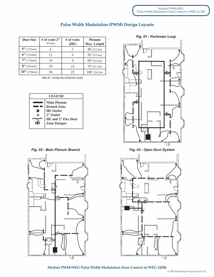
Each basic layout has it’s typical applications. For example, the Perimeter Loop and Main Branch Layouts are best served doing multi-zones of 4 or more, with the Open Duct best servicing 2 - 4 zones. Perimeter Loop works well in a single level application, while the Main branch is better suited for multi-level applications.
The Main Plenum Branch method is similar to a Perimeter Loop, in that you direct the main plenum to the area loads, with branch tees directing each zone to the outlets, once again installing zone dampers.
Whichever method of zoning layout is utilized, it continues to be important for Indoor Air Quality that a certain amount of air is by-passed through each zone. This air recirculation is also important for Energy Efficiency, and even though the zone may not be calling for it, the recirc air will aid in overall living comfort.
In some installations, it is necessary to reduce the size of the main plenum. Caution must be used when reducing plenum size, since smaller ducts can handle less number of outlets. Also keep in mind that once reduced, the main
There are three basic layout styles to be used with the PWM controller: the Perimeter Loop/Branch (Fig. 01), the Main Plenum Branch (Fig. 02), and the Open Duct standard design (Fig. 03).
The Open Duct layout is the same concept that is used in the Hi-Velocity Design Manual. This method utilizes the branch split and bullhead tees planning of air flow, with each zone being individually controlled.
When designing the perimeter loop, first determine the system load and individual zones. Locate the Fan Coil and vent outlets as per the design manual. Design the Perimeter Loop with the proper diameter 8” or 10” duct, as determined by the fan coil unit. Use appropriate plenum duct size around the perimeter of the structure.
When sizing the branch zone plenum off the Perimeter Loop, use the Zoning Duct Reduction Guide. (Table 01). Total the outlets for each individual zone to determine the zone plenum duct diameter. Locate the tee servicing this zone to minimize the zone plenum duct, and run the plenum where it’ll be possible to keep the AFD duct to 10’ and 15’ lengths. There is no minimum length on the Zone Main Plenum run. For maximum length allowed refer to the Zoning Duct Reduction Guide. (Table 01)
The Perimeter Loop layout is as the term implies. A perimeter loop of plenum duct is installed in the structure, from there branch tees are installed for each zone dependant on the zone size, and a zone damper is installed for each take-off/zone. The Main Plenum also requires that a comprehensive system
load is completed, zones determined, fancoil and outlets located as per the design manual. The Plenum duct is then located to direct the air to the loads at each zone, and elbow and tees can be located where required, as per the design manual.
The zone duct diameter is determined from the duct reduction guide (Table 01) and an appropriate balanced tee installed. Locate the tee servicing this zone to minimize the zone plenum duct, and run the plenum where it’ll be possible to keep the AFD duct to 10’ and 15’ lengths. There is no minimum length on the Zone Main Plenum run. For maximum length allowed refer to the Zoning Duct Reduction Guide. (Table 01)
The Open Branch layout utilizes the Hi-Velocity Design Manual in its entirety, from Load calculation to duct location. This method is best suited when 2 - 4 zones are utilized, by following the design manual and duct reduction guide if necessary. You will either branch or bullhead the tees to 1 or 2 zones, and continue the plenum to the furthest run, installing zone dampers where required.
The PWM is a pressure reactive Zone Controller that will change the energy input to maintain constant CFM flow of open outlets from 150 cfm to 1250 cfm, eliminating the need for by-pass dampers. The PWM controller has three independent settings for Cooling, Heating and Recirc. Fan, allowing for fine tuning with variable commands. The PWM unit is compatible with most forced air zoning packages and has been successfully integrated with Inverter Drive Heat Pump Condensing Units, providing leading edge technology for unsurpassed comfort and energy efficiency.
plenum cannot be increased again. The Branch Take Offs easily form to ducts in the 6” to 8” range; extra care must be taken with smaller sized ducts to ensure a proper air seal. For tee reductions, keep the tee to the full duct size, reducing only after the tee. Keep the length of the smaller duct sizes to a minimum, since the duct loss is much higher. If a hole saw will be used to drill the branch take-off holes, metal ducts are recommended to be 28 gauge steel.
Module PWM-WEG Pulse Width Modulation Zone Control w/ WEG (2/28)
Module PWM-WEGPulse Width Modulation Zone Control w/WEG (2/28)
2
Layout Design
Perimeter Loop (Fig. 01)
Main Plenum Branch (Fig. 02)
Open Duct System (Fig. 03)
Pulse Width Modulation (PWM) Design & Installation Guide
© 1995-2012 Energy Saving Products Ltd.
Fig. 01 - Perimeter Loop
Fig. 02 - Main Plenum Branch
LEGEND
Main PlenumBranch ZoneHE Outlet2” OutletHE and 2” Flex DuctZone Damper
Fig. 03 - Open Duct System
Duct Size # of vents 2” (51mm)
# of vents (HE)
PlenumMax. Length
5” (127mm) 6 3 40’ (12.2m)
6” (152mm) 12 6 50’ (15.2m)
7” (178mm) 19 9 60’ (18.3m)
8” (203mm) 29 14 70’ (21.3m)
10” (254mm) 50 25 100’ (30.5m)
Module PWM-WEG Pulse Width Modulation Zone Control w/ WEG (3/28)
Module PWM-WEGPulse Width Modulation Zone Control w/WEG (3/28)
3
Pulse Width Modulation (PWM) Design Layouts
Table 01 - Zoning Duct Reduction Guide

© 1995-2012 Energy Saving Products Ltd.Module PWM-WEG Pulse Width Modulation Zone Control w/ WEG (4/28)
Module PWM-WEGPulse Width Modulation Zone Control w/WEG (4/28)
4
The location of the Pressure Tap is important for proper operation. Assure that it is located a minimum of 18” (457mm) downstream from the fancoil. 36” (914mm) downstream provides the most consistent reading, located before any dampers. If an elbow or tee is installed before the tap, then the tap must be a minimum of 18” (457mm) downstream from that point.
Begin by drilling a 3/4” (127mm) hole in the plenum at the desired point. (Fig. 05)
Assuring that the pressure tap is over the hole, Attach pressure tap with (8) 5/16” self tapping screws provided. (Fig. 06)
BE SURE TO READ ALL INSTRUCTIONS PRIOR TO BEGINNING INSTALLATION!
Fig. 05 - Drill 3/4” (13mm) hole
Quick acting, spring shut dampers are not to be used with the PWM control. Instead, it is suggested to use a slow acting electronic damper, which gives the PWM controller adequate time to adjust to variations in duct pressure.
Connect the power supply, control and thermostat wiring as per wiring diagram on page 7. For more information and detailed wiring diagrams, refer to the HE Series Installation Manual.
Ensure that there are no kinks in the air lines as this may hinder performance. The positive marked air line is to be connected to the Pressure Tap. The shorter air line, marked with a negative sign, is to be mounted on the exterior of the unit, to sense atmospheric pressure. Ensure that this line is mounted facing downwards to prevent any accumulation of debris. Do not block or restrict any air lines. (Fig. 04)
Fig. 02 - Port Markings
Using the 1/4” tubing provided, connect the air lines to their designated ports on the PWM circuit box. The air lines provided are marked with a positive or negative sign. Each line is to be connected to it’s respective quick connect port on the outside of the PWM circuit box. These ports are marked with a matching positive or negative sign. (Fig. 02)
Fig. 03 - Air Lines
Fig. 04 - Air Lines
The PWM Controller is compatible with most Forced Air Zoning Packages. Zoning control panels with a Recirculation Fan Option are strongly recommended, so as to utilize continuous air circulation for optimal Indoor Air Quality (IAQ) and Energy Efficiency. Independent testing has shown that utilizing the recirculation fan with the Hi-Velocity Systems EPC motor reduces total energy usage. This is due to less on/off cycling of AC and Heating equipment by constant de-stratification of the air.
PWM Installation
Pressure Tap Location & Installation
Mounting the Pressure TapRoute both air lines to the exterior of the fan coil through one
of the three holes located on the side of the fan coil, inserting the provided plastic grommet into the chosen hole before running air lines. (Fig. 03) Run air lines to the outside of the unit through the provided grommet. The air lines may be secured to the unit by the supplied plastic conduit straps. (Fig. 03)
Installing the PWM Zone Controller

© 1995-2012 Energy Saving Products Ltd.5
To set the PWM Controller, the required airflow capacity must be determined for each operating mode. The required CFM/Ton (l/s per kW) is 250 (34), 200 (27), and 125(17) for Cooling, Heating and Recirculation Fan respectively. Divide the total CFM required for each fan speed by the total number of outlets. Keep in mind that each HE outlet represents 2 standard outlets. This will provide the average CFM per outlet.
With the PWM module hooked into the circuit board, control board and the duct work, you can go about adjusting the trimpots to your desired performance. Make sure everything internally to the unit is reconnected.
For full and proper tuning of the PWM controller, repeat the above process for heating and recirculation fan.
When tuning is complete, cycle all zone dampers to verify total system operation.
With the basic programming set, you are now ready to fine tune the PWM Controller. With the power on, all zone dampers opened, and the cooling energized, allow the fan 2 minutes to fully ramp up. Once the fan is fully ramped up, read and record airflow readings from all of the outlets. Total the cfm output of all outlets, and divide that number by the total number of outlets, to find the mean average. Keep in mind that each HE outlet represents 2 standard outlets. Select one outlet that is representative of this average, and use that outlet as a base reference for further adjustment. Increase or decrease the trim pot to obtain the ideal average cfm, using the average outlet as a tuning guide. Finally, once again read and record total airflow for cooling mode, to assure proper total cfm.
- Using a controls screwdriver, adjust the appropriate trim pot. (Cooling, Heating, or Recirculation Fan) A clockwise turn will increase the airflow output, while a counter-clockwise turn will decrease the airflow. Be sure to take note of the red LED light present on the PWM controller.
Recirculation FanHeating
(W2 terminal)
Cooling (Y2 Terminal)
- Ensure air lines are correctly mounted and secured- Power Unit- Ensure all zones and outlets are open- Energize the thermostat setting to be adjusted. (Cooling, Heating, or Recirculation Fan)
Fig. 07 - Quick Connect
Fig. 06 - Attach pressure tap
Connect the positive air line to the quick connect fitting on the pressure tap. (Fig. 06) This line is to be connected at the opposite end to the PWM Controller through the positive fitting. (Fig. 07) - When the PWM controller has reached the set point and is
operating within an acceptable range, the red LED light on the PWM controller will flicker sporadically on and off to show that it is properly sensing pressure in the system.
- Be sure to wait 45 seconds between adjustments to allow the PWM controller to reach and maintain the set point.
- If the light on the PWM controller remains either off or on after 45 seconds, the current set point is outside the normal operating range and must be adjusted accordingly:
* No light indicates that the trim pot is above normal operating range and should be decreased (counter-clockwise).
* A solid light indicates that the trimpot is below normal operating range and should be increased (clockwise).
- When all trim pots have been adjusted to normal operating conditions, fine tuning of the PWM controller may commence.
Setting the PWM Device
Basic Programming
Fine Tuning the PWM Controller
Module PWM-WEG Pulse Width Modulation Zone Control w/ WEG (5/28)
Module PWM-WEGPulse Width Modulation Zone Control w/WEG (5/28)

© 1995-2012 Energy Saving Products Ltd.6
• Initial programming of the PWM Controller for cooling, heating and recirculation fan must be done with all dampers in the open position, to verify maximum load capacities.
• To find outlet CFM: Multiply Knots by 2.2 for 2”, and by 4.2 for HE Multiply FPM by 0.022 for 2” and by 0.042 for HE
• As the PWM controller takes up to 45 seconds to adjust to changes in duct pressure, the use of slow acting electronic dampers is suggested for proper operation of the PWM controller. Fast acting spring return dampers are not to be used.
• To find outlet L/s: Multiply Knots by 1.4 for 2”, and by 1.98 for HE
Multiply m/s by 2.02 for 2” and by 3.85 for HE
Module PWM-WEG Pulse Width Modulation Zone Control w/ WEG (6/28)
Important Notes
Installation Notes:
Module PWM-WEGPulse Width Modulation Zone Control w/WEG (6/28)

© 1995-2012 Energy Saving Products Ltd.7
NOTES:
ATTENTIONDECCONNECTER DU CIRCUIT
D’ALIMENTATION ELECTRIQUEAVANT L’ENTRE-TIEN
DISCONNECT THE ELECTRICPOWER BEFORE SERVICING
CAUTION
- FREEZE STAT TERMINAL- FREEZE STAT TERMINAL- CONDENSING UNIT 24v OUTPUT- CONDENSING UNIT 24 VAC COMMON- HEATING MODE 24v OUTPUT- 24 VAC COMMON
X1X2H1C
Z1C
- NEUTRAL- LINE VOLTAGE- AUXILIARY NORMALLY OPEN- AUXILIARY NORMALLY CLOSED- AUXILIARY COMMON
NL
A1A2A3
ESP 318.20MAR.12
PWM / WEG WIRING
5M
INU
TE
TIME
R
24HO
N
OFF
Z1C
H1
X2X1
C
W1
W2
CR
Y2Y1
DO
/BG
AU
XILIA
RY
RE
LAY(H
EA
TING
)
A3
A2
A1 LN
NN
LL
NL
L
R
Red Wire
N
N
F124v
(F1-R
esettablefuse)
24v/20va
TR
AN
SF
OR
ME
R
U-
RE
DM
OT
OR
LE
AD
V-
WH
ITE
MO
TO
RL
EA
DW
-B
LA
CK
MO
TO
RL
EA
D
12
34
56
78
910
1112
L/L
1N
/L2
UV
WP
E
WE
GE
AS
YD
RIV
E P 0I
Par
amet
er
Val
ue
L/L1N/L2
Ground
GW
HB
K
LINE IN
Fan Heat Cool
R C 1Y2 1W2 GJ1
LJ2
U2
R5R6R7
J3
L51
9B1
GEQUIPMENT
GROUND
G-
GR
EE
NM
OT
OR
LE
AD
POWER CABLE
EPC CIRCUIT BOARD
CIRCUIT BOARDINTERFACE CABLE
PWM INTERFACECABLE
WEG CONTROLLER
+
-
NOTES:1)
2)
3)
4)
5)
6)
USE THERMOSTAT FAN SWITCH TODISABLE/ENABLE CONTINUOUS FAN.‘C’ TERMINAL ON THERMOSTAT (COMMON)IS NOT NEEDED FOR SOME THERMOSTATSCONSULT THERMOSTAT INSTRUCTIONSFOR DETAILS.A3 (AUXILIARY RELAY COMMON) CAN BEUSED WITH A1 AND/OR A2 AS DRYCONTACTS, ARMED 24v FROM THE ‘R’TERMINAL, OR ARMED FROM THE‘L’ TERMINAL.AUXILIARY RELAY TIMER ACTIVATESCIRCUIT FOR 5 MINUTES EVERY 24 HOURSSTARTING WHEN POWER IS APPLIED TOTHE UNIT. RED LIGHT FLASHES WHEN TIMERIS ACTIVATED AND THAN TURNS ON SOLID.SEE INSTALLATION MANUAL FOR MOREDETAILED WIRING DIAGRAMS.FAILURE TO READ AND FOLLOW ALLINSTRUCTIONS CAREFULLY BEFOREINSTALLATION COULD CAUSE PERSONALINJURY AND/OR PROPERTY DAMAGE.
NOTE: 115V OR 230V* DEPENDENT UPON WEG CONTROLLER
MODEL. CONSULT WEG RATING PLATEFOR INFORMATION.
SINGLE STAGE OPERATIONUSE W2 & Y2 TERMINALS
MOTORLEADS
PWM CIRCUIT BOX
318.
20P
cbw
-001
sep
-037
- ENSURE THAT THE FILTER IS KEPT CLEAN AT ALL TIMES.- MOTOR HAS PERMANENT LUBE BEARINGS AND DOES
NOT REQUIRE OILING.- WARRANTY VOID IF FAN COIL UNIT IS USED DURING
CONSTRUCTION.
ATMOSPHERIC PRESSURE
DUCT PRESSURE+-
WARNING: HIGH VOLTAGE
AVERTISSEMENT: HAUT VOLTAGE
THIS DEVICE CONTAINS CAPACITORS WHICH STOREPOTENTIALLY DANGEROUS AMOUNTS OF ENERGY.
ALLOW 10 MINUTES AFTER DISCONNECTING POWERFROM THE DRIVE BEFORE DISCONNECTING THE MOTOR.
CET APPAREIL EST MUNI DECONDENSATEURS QUI EMMAGASINENT UN MONTANT
D’ÉNERGIE POTENTIELLEMENT DANGEREUX.AVANT DE DÉCONNECTER LE MOTEUR, ATTENDRE
10 MINUTES APRÈS AVOIR DÉBRANCHÉ L’ALIMENTATIONÉLECTRIQUE DE LA DRIVE.
Module PWM-WEG Pulse Width Modulation Zone Control w/ WEG (7/28)
HE Fan Coil - PWM w/WEG Wiring Diagram
Module PWM-WEGPulse Width Modulation Zone Control w/WEG (7/28)

© 1995-2012 Energy Saving Products Ltd.8
*To adjust the remaining T-Stat settings: - Jumper between R & the desired T-Stat setting - Adjust the corresponding trimpot to the desired airflow using the method described in the PWM Design, Installation and Operation Manual. - Begin with the “Basic Programming” section (Pg. 5) then: - Continue with the “Fine Tuning the PWM Controller” Section (Pg.5)
N
Fig. 003
Fig. 004
Fig. 005
Fig. 006
Ensure transformer is connected properly.
Inspect supply voltage.Supply power present?
Verify that 24VAC is present between C & desired T-Stat setting.
EPC circuit board is functioning correctly.
Verify that PWM circuit boxis functioning within
proper operating range.
Light present on PWM circuit board?
Verify that PWM circuit box is functioning properly by
measuring voltage output (Volts DC) at the WEG
controller, terminals 7 & 8.*See Fig. 005
Voltage present? (0-5VDC)
VDC < 4VDC
Read and record Volts DC value.
Adjust trimpot counter-clockwise 1/2 turn.
Read and record Volts DC value to confirm adjustment.
VDC changed?
PWM circuit box functioning correctly.
Adjust trimpots in PWM circuit box until airflow isrunning at desired speed.
*See PWM Design, Installation and Operation manual - Pg.5
Ensure that jumper is installed correctly.
*See Fig. 002
Turn PWM trimpot counter-clockwise
1/2 turn, wait 30-45 seconds for drive to adjust. Return to Step 9.
Ensure that volt meter is set to read Volts DC. Test voltage on
opposite end of cable. *See Fig. 006
Decrease trimpot of jumpered tstat setting 1/2 turn counter-clockwise.Wait 30 seconds for
motor to adjust. *See Fig. 007
Adjust 1/2 turn counter-clockwise,
wait 30-45 seconds. VDC changed?
Return to Step 4.
Replace transformer.
Turn off supply power, connect transformer, turn on power.
Return to Step 5.
Call Technical Support Toll Free 1-888-652-2219.
Install jumper and return to Step 6.
Voltage Present?
Continue adjustments until VDC < 4VDC.
(Again) Adjust 1/2 turn counter-clockwise,
wait 30-45 seconds. VDC changed?
Return to Step 15.
Return to Step 13.
Change PWM circuit box.
Return to Step 11.
Call Technical Support Toll Free 1-888-652-2219.
10
9
8
7
6
5
4
Verify that main supply voltage ispresent on the EPC circuit boardbetween the L and N terminals.
*See Fig. 003
3
Power fan coil.2
11
17
16
15
14
13
18
N
Y
Y
Y
Y
N
N
N
N
N
N
12
Y
Y
Y
N
Y
Y
N
N
Y
N
Y
Verify that 24VAC is present between R & C on
the EPC circuit board*See Fig. 004
Return to Step 12.
Y
Recirc. Fan (G terminal)
Heating (W2 terminal)
Cooling (Y2 terminal)
Fig. 007
Fig. 002Fig. 001
Module PWM-WEG Pulse Width Modulation Zone Control w/ WEG (8/28)
Troubleshooting - Motor Running Too Fast
Module PWM-WEGPulse Width Modulation Zone Control w/WEG (8/28)
1
Start
Jumper desired Tstat setting with R on the EPC circuit board.
*See Figs. 001-002

© 1995-2012 Energy Saving Products Ltd.9
Fig. 007 Fig. 008
Fig. 003
Fig. 006
Fig.004
Fig. 005
Fig. 002Fig. 001
Use clamp on amp meter to test amperage of input power
supply to the fan coil. *See Fig. 008
PWM circuit box & WEG controller functioning correctly.
Motor running?
Motor working correctly.
Call Technical Support @ 1-888-652-2219.
PWM circuit board working correctly -
Replace WEG controller.
17
16
15
14
18
Y
N
Y
N
Call Technical Support Toll Free 1-888-652-2219.
Amperage > 2A ( 1 amp @ 220-240 volt AC)
Voltage present? (0-5VDC)
VDC > 4VDC
PWM circuit box is functioning correctly.
Ensure that volt meter is set to read Volts DC. Test voltage on
opposite end of cable. *See Fig. 007
Increase trimpot 1/2 turn clockwise.Wait 30 seconds for
motor to adjust.
Voltage present?
Continue to Step 11.
1
10
12
Y
Y
N
N11
Ensure transformer is connected properly.
Inspect supply voltage.Return to Step 5.Supply Power Present?
Verify that 24VAC is present between R & C on
the EPC circuit board.*See Fig. 005
Verify that 24VAC is present between C & desired T-Stat setting.
EPC circuit board is functioning correctly.
Ensure that jumper is installed correctly.
*See Fig. 002
Replace transformer.
Turn off supply power, connect transformer, turn on power.
Return to Step 6.
Call Technical Support Toll Free 1-888-652-2219.
Install jumper and return to Step 7.
9
8
7
6
5
Verify that main supply voltage ispresent on the EPC circuit boardbetween the L and N terminals.
*See Fig. 004
4
Power fan coil.3
N
N
N
Y
Y
Y
N
Y
N
N
Y
Unscrew motor leads and test resistance (ohms)
between windings.*See Fig. 003
Start
Jumper desired Tstat setting with R on the EPC circuit board.
*See Figs. 001-002
Verify that PWM circuit boxis energized by measuring
voltage output (Volts DC) @ the WEG controller, terminals 7 & 8.
*See Fig. 006
2
Y
Call Technical Support Toll Free 1-888-652-2219.
XIf resistance is outside of the
acceptable range (6.5 - 10.5 ohms) or uneven
across any winding legs, call Technical Support
Toll Free @ 1-888-652-2219.If resistance is acceptable,
re-connect motor leads and continue to Step 3.
Adjust trimpots in PWM circuit box until airflow is running at desired speed.
*See PWM Design, Installation and Operation
Manual - Pg.5
Continue adjustments until VDC > 4VDC. Return to Step 12.
Resistance should be equalbetween all windings. Black to red, black to white and red to white. Resistance should be:
6.5 - 10.5 ohms
Module PWM-WEG Pulse Width Modulation Zone Control w/ WEG (9/28)
Module PWM-WEGPulse Width Modulation Zone Control w/WEG (9/28)
Troubleshooting - Motor Running Too Slow

© 1995-2012 Energy Saving Products Ltd.10
Voltage present? (0-5VDC)
VDC > 4VDC
PWM circuit box is functioning correctly.
Ensure that volt meter is set to read Volts DC. Test voltage on
opposite end of cable. *See Fig. 007
Increase trimpot 1/2 turn clockwise.Wait 30 seconds for
motor to adjust.
Continue adjustments until VDC > 4VDC. Return to Step 12.
Continue to Step 11.
Call Technical Support Toll Free 1-888-652-2219.
1
10
12
Y
Y
N
N11
Ensure transformer is connected properly.
Inspect supply voltage.Return to Step 5.Supply Power Present?
Verify that 24VAC is present between R & C on
the EPC circuit board.*See Fig. 005
Verify that 24VAC is present between C & desired T-Stat setting.
EPC circuit board is functioning correctly.
Ensure that jumper is installed correctly.
*See Fig. 002
Replace transformer.
Turn off supply power, connect transformer, turn on power.
Return to Step 6.
Call Technical Support Toll Free 1-888-652-2219.
Install jumper and return to Step 7.
9
8
7
6
5
Verify that main supply voltage ispresent on the EPC circuit boardbetween the L and N terminals.
*See Fig. 004
4
Power fan coil.3
N
N
N
Y
Y
Y
N
Y
N
N
Y
Unscrew motor leads and test resistance (ohms)
between windings.*See Fig. 003
Start
Jumper desired Tstat setting with R on the EPC circuit board.
*See Figs. 001-002
Resistance should be equalbetween all windings. Black to red, black to white and red to white. Resistance should be:
6.5 - 10.5 ohms
Verify that PWM circuit boxis energized by measuring
voltage output (Volts DC) @ the WEG controller, terminals 7 & 8.
*See Fig. 006
2
Y
Fan running? N
Y
13Ensure red plug in PWM box is
properly connected.*See Fig. 008
Fan Running?
Adjust trimpots in PWM circuit box until airflow is running at desired speed.
*See PWM Design, Installation and Operation
Manual - Pg.5
Y
N
Call Technical Support Toll Free 1-888-652-2219.
14
XIf resistance is outside of the
acceptable range (6.5 - 10.5 ohms) or uneven
across any winding legs, call Technical Support
Toll Free 1-888-652-2219.If resistance is acceptable,
re-connect motor leads and continue to Step 3.
Voltage present?
Fig. 003
Fig. 006
Fig. 004
Fig. 005
Fig. 002Fig. 001
Module PWM-WEGPulse Width Modulation Zone Control w/WEG (10/28)
Module PWM-WEG Pulse Width Modulation Zone Control w/ WEG (10/28)
Troubleshooting - Motor Not Running
Fig. 007 Fig. 008
© 1995-2012 Energy Saving Products Ltd.11
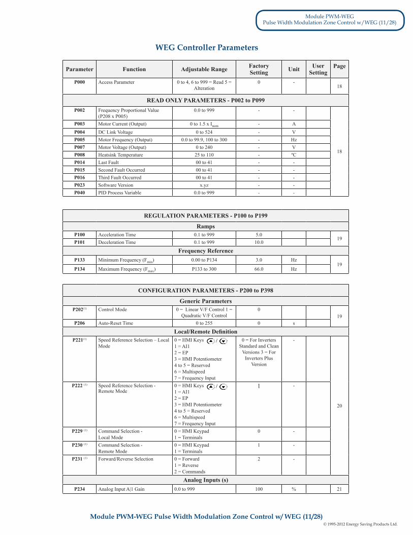
Parameter Function Adjustable Range Factory Setting Unit User
SettingPage
P000 Access Parameter 0 to 4, 6 to 999 = Read 5 = Alteration
0 -18
READ ONLY PARAMETERS - P002 to P099P002 Frequency Proportional Value
(P208 x P005)0.0 to 999 - -
18
P003 Motor Current (Output) 0 to 1.5 x Inom - AP004 DC Link Voltage 0 to 524 - VP005 Motor Frequency (Output) 0.0 to 99.9, 100 to 300 - HzP007 Motor Voltage (Output) 0 to 240 - VP008 Heatsink Temperature 25 to 110 - ºCP014 Last Fault 00 to 41 - -P015 Second Fault Occurred 00 to 41 - -P016 Third Fault Occurred 00 to 41 - -P023 Software Version x.yz - -P040 PID Process Variable 0.0 to 999 - -
CONFIGURATION PARAMETERS - P200 to P398
Generic ParametersP202(1) Control Mode 0 = Linear V/F Control 1 =
Quadratic V/F Control0
19P206 Auto-Reset Time 0 to 255 0 s
Local/Remote DefinitionP221(1) Speed Reference Selection – Local
Mode0 = HMI Keys 1 = AI12 = EP3 = HMI Potentiometer4 to 5 = Reserved6 = Multispeed7 = Frequency Input
0 = For Inverters Standard and Clean
Versions 3 = For Inverters Plus
Version
-
20
P222 (1) Speed Reference Selection - Remote Mode
0 = HMI Keys 1 = AI12 = EP3 = HMI Potentiometer4 to 5 = Reserved6 = Multispeed7 = Frequency Input
1 -
P229 (1) Command Selection - Local Mode
0 = HMI Keypad 1 = Terminals
0 -
P230 (1) Command Selection - Remote Mode
0 = HMI Keypad 1 = Terminals
1 -
P231 (1) Forward/Reverse Selection 0 = Forward1 = Reverse2 = Commands
2 -
Analog Inputs (s)P234 Analog Input A|1 Gain 0.0 to 999 100 % 21
REGULATION PARAMETERS - P100 to P199
RampsP100 Acceleration Time 0.1 to 999 5.0
19P101 Deceleration Time 0.1 to 999 10.0
Frequency ReferenceP133 Minimum Frequency (Fmin) 0.00 to P134 3.0 Hz
19P134 Maximum Frequency (Fmax) P133 to 300 66.0 Hz
WEG Controller Parameters
Module PWM-WEGPulse Width Modulation Zone Control w/WEG (11/28)
Module PWM-WEG Pulse Width Modulation Zone Control w/ WEG (11/28)

© 1995-2012 Energy Saving Products Ltd.12
Display Description PageE00 Output Overcurrent/Short-Circuit
22
E01 DC Link Overvoltage
E02 DC Link Undervoltage
E04 Inverter Overtemperature
E05 Output Overload (I x t function)
E06 External Fault
E08 CPU Error (watchdog)
E09 Program Memory Error (checksum)
E24 Programming Error
E31 Keypad (HMI) Communication Fault 97
E41 Self-Diagnosis Error 97
Display Descriptionrdy Inverter is ready to be enabled
Sub Power supply voltage is too low for the inverter operation (undervoltage)
dcb Inverter in DC braking mode
EPP Inverter is loading factory setting
Fault Messages
Other Messages
Safety NoticesThis manual contains necessary information for the correct use of the CFW-10 Variable Frequency Drive.This manual has been written for qualified personnel with suitable training and technical qualification to operate this type of equipment.
Safety Notices in the Manual
DANGER!If the recommended Safety Notices are not strictly observed, it can lead to serious or fatal injuries of personnel and/or material damage.
ATTENTION!Failure to observe the recommended Safety Procedures can lead to material damage.
NOTE!The content of this manual supplies important information for the correct understanding of operation and proper performance of the equipment.
High Voltages
Components sensitive to electrostatic discharge. Do not touch them without proper grounding procedures.
Mandatory connection to ground protection (PE).
Shield connection to ground
Safety Notices on the Product
Module PWM-WEGPulse Width Modulation Zone Control w/WEG (12/28)
Module PWM-WEG Pulse Width Modulation Zone Control w/ WEG (12/28)

© 1995-2012 Energy Saving Products Ltd.13
DANGER!Only qualified personnel should plan or implement the installation, start-up, operation and maintenance of this equipment. Personnel must review entire manual before attempting to install, operate or troubleshoot the CFW-10.These personnel must follow all safety instructions included in this manual and/or defined by local regulations.Failure to comply with these instructions may result in personnel injury and/or equipment damage.
NOTE!In this manual, qualified personnel are defined as people that are trained to:1. Install, ground, power up and operate the CFW-10 according to this manual and the local required safety procedures; 2. Use of safety equipment according to the local regulations;3. Administer First Aid.
DANGER!The inverter control circuit (CCP10, DSP) and the HMI-CFW-10 are not grounded. They are high voltage circuits.
DANGER!Always disconnect the supply voltage before touching any electrical component inside the inverter.Many components are charged with high voltages, even after the incoming AC power supply has been disconnected or switched OFF.Wait at least 10 minutes for the total discharge of the power capacitors.
Always connect the frame of the equipment to the ground (PE) at the suitable connection point.CFW-10 drive must be grounded appropriately for safety purposes (PE).
ATTENTION!All electronic boards have components that are sensitive to electrostatic discharges. Never touch any of the electrical components or connectors without following proper grounding procedures. If necessary to do so, touch the properly grounded metallic frame or use a suitable ground strap.
Do not apply High Voltage (High Pot) Test on the inverter!If this test is necessary, contact the Manufacturer.
NOTE!Inverters can interfere with other electronic equipment. In order to reduce this interference, adopt the measures recommended in Section 3 “Installation”.
NOTE!Read this entire manual carefully and completely before installing or operating the CFW-10.
Preliminary Recommendations
CFW-10 Identification
WEG Part Number
Software Version
Manufacturing Date
CFW-10 Model
Rated Output Data (Voltage, Frequency)
Rated Input Data(Voltage, Current, etc)
Serial NumberLateral Nameplate CFW-10
Module PWM-WEGPulse Width Modulation Zone Control w/WEG (13/28)
Module PWM-WEG Pulse Width Modulation Zone Control w/ WEG (13/28)
Fig. 8 - WEG Controller
Fig. 9 - WEG Nameplate

© 1995-2012 Energy Saving Products Ltd.14
This chapter describes the CFW-10 operation via Human-Machine Interface (HMI), providing the following information:
General keypad description (HMI);
Use of the keypad (HMI);
Inverter parameters arrangement;
Alteration mode parameters (programming);
Description of the status indicators.
RRRR
The standard CFW-10 keypad has a LED display with 3 digits of 7 segments, 2 status LEDs and 4 keys. Figure 4.1 shows the front view of the keypad and indicates the position of the Display and the status LEDs. CFW-10 Plus version still has a potentiometer for speed setting.
LED DisplayLED “Parameter”
LED “Value”
Potentiometer (Only available on Plus version)
Fig. 10 - CFW-10 keypad (HMI)
Functions of the LED Display:The LED Display shows the fault and status messages (see Quick Parameter Reference, Fault and Status), the parameter number and its value.
Functions of the LED´s “Parameter” and “Value”:Inverter indicates the parameter number:Green LED OFF and red LED ON.
Inverter indicates the parameter content:Green LED ON and red LED OFF.
Potentiometer Function:Increase/Decrease the speed (only available on Plus version)
R
Keypad (HMI) Operation
Keypad (HMI) Description
Module PWM-WEGPulse Width Modulation Zone Control w/WEG (14/28)
Module PWM-WEG Pulse Width Modulation Zone Control w/ WEG (14/28)

© 1995-2012 Energy Saving Products Ltd.15
Enables/disables the inverter via acceleration/deceleration ramp (run/stop). Resets the inverter after a fault trip.
Selects (commutates) the display between parameter number/value (position/content).
Increases the frequency, the parameter number or the parameter value.
Decreases the frequency, the parameter number or the parameter value.
Use of the Keypad (HMI)
Keypad (HMI) Operation
The Keypad (HMI) is a simple interface that allows inverter operation/programming. This interface has the following functions: General keypad description (HMI);
Indication of the inverter status and operation variables;
Fault indication and diagnostics;
Viewing and programming parameters;
Inverter operation (key ) and speed reference setting (keys and )
Potentiometer for the output frequency variation (only in the Plus version).
RRRRR
All functions relating to the CFW-10 operation (Start/Stop, Increment/Decrement of the Speed Frequency) can be performed through the HMI selection. For factory default programming of the inverter, all keypad keys are enabled. These functions can be carried out through digital and analog inputs. Thus you must program the parameters related to these corresponding inputs.
NOTE!The command key will be enabled only when:
P229 = 0 for LOCAL Mode operation
P230 = 0 for REMOTE Mode operation
See below the keypad functions description:
RR
When pressed, motor accelerates according to acceleration ramp up to the speed (frequency) reference. The function is similar to that performed through digital input START/STOP, when it is closed (enabled) and maintained enabled.
When pressed again, inverter is disabled via ramp (motor accelerates according to acceleration ramp and stops). The function is similar to that performed through digital input START/STOP, when it is opened (disabled) and maintained disabled.
Module PWM-WEGPulse Width Modulation Zone Control w/WEG (15/28)
Module PWM-WEG Pulse Width Modulation Zone Control w/ WEG (15/28)
Basic Functions of the Keys:

© 1995-2012 Energy Saving Products Ltd.16
and Motor speed (frequency) setting: these keys are enabled for speed setting only when:
The speed reference source is the keypad (P221 = 0 for LOCAL Mode and/or P222 = 0 for REMOTE Mode);
The following parameter content is displayed: P002, P005 or P121.
Parameter P121 stores the speed reference set by these keys.
When pressed, it increases the speed (frequency) reference.
When pressed, it decreases the speed (frequency) reference.
Reference BackupThe last frequency reference, set by the keys and , is stored when inverter is stopped or the AC power is removed, provided P120 = 1 (reference backup active is the factory default). To change the frequency reference before inverter is enabled, you must change the value of the parameter P121.
NOTE!On CFW-10 Plus version, the motor frequency setting function is made through the HMI potentiometer. However, it is possible to set the motor frequency through the keys since P221/P222 parameters were programmed.
Inverter Status - HMI DisplayInverter Status:
NOTE!Besides the fault conditions, the display also flashes when the inverter is in overload condition
(refer to Diagnostics and Troubleshooting Section).
Inverter is READY to be started.
Line voltage is too low for inverter operation (undervoltage condition).
Inverter is in a Fault condition. Fault code is flashing on the display. In our example we have the fault code E02 (refer to chapter 7).
Inverter is applying a DC current on the motor (DC braking) according to the values programmed at P300, P301 and P302 (refer to chapter 6).
Inverter is running self-tuning routine to identify parameters automatically. This operation is controlled by P204 (refer to chapter 6).
Module PWM-WEGPulse Width Modulation Zone Control w/WEG (16/28)
Module PWM-WEG Pulse Width Modulation Zone Control w/ WEG (16/28)
Keypad (HMI) Operation Cont’d

© 1995-2012 Energy Saving Products Ltd.17
ACTION HMI DISPLAY DESCRIPTION
Turn ON the inverter Inverter is ready to be started
Use the keys and Select the desired parameter
Press the key Numerical value associated with the parameter (4)
Use the keys and Set the new desired value (1) (4)
Press the key (1) (2) (3)
Parameters from P002 to P008 are reserved for the display of read-only variables.
When the inverter is powered up, the display will indicate the value of the Parameter P002 (output frequency value).
Parameter Viewing and ProgrammingAll inverter settings are made through parameters.
Parameters and their contents are shown on the Display through the LED´s “ Parameter” and “Value”. The identification is made between parameter number and its value.
Example (P100):Parameter
Value
100 = Parameter Number 5.0 = Parameter Value
NOTE!(1) For parameters that can be changed with the running motor, the inverter will use the new value immediately after it has been set.For parameters that can be changed only with stopped motor, the inverter will use this new value only after the key is pressed.(2) By pressing the key after the reprogramming, the new programmed value will be saved automatically in the volatile memory and will remain stored there until a new value is programmed.
(3) If the last programmed value in the parameter is not functionally compatible with the other parameter values already programmed, the E24 = Programming Error - will be displayed.
(4) To change any paramater value, you must set before P000 = 5. Otherwise you can only read the parameter values, but not reprogram them. For more details, see P000 description in Chapter 6.
Example of programming error:Programming of two digital inputs (DI) with the same function. Refer to table 4.1 for list of programming errors that can generate an E24 Programming Error.
Parameter
Value
Module PWM-WEGPulse Width Modulation Zone Control w/WEG (17/28)
Module PWM-WEG Pulse Width Modulation Zone Control w/ WEG (17/28)
Read-Only Variables
© 1995-2012 Energy Saving Products Ltd.18
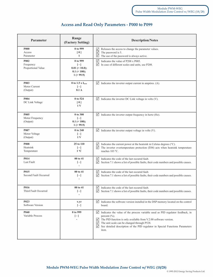
Parameter Range (Factory Setting) Description/Notes
P000Access Parameter
0 to 999[ 0 ]
1
Releases the access to change the parameter values.The password is 5. The use of the password is always active.
P002Frequency Proportional Value
0 to 999[ - ]
0.01 (< 10.0);0.1 (< 100);1 (> 99.9)
Indicates the value of P208 x P005.In case of different scales and units, use P208.
P003Motor Current (Output)
0 to 1.5 x Inom
[ - ]0.1 A
Indicates the inverter output current in ampères. (A).
P004DC Link Voltage
0 to 524[ 0 ]1 V
Indicates the inverter DC Link voltage in volts (V).
P005Motor Frequency (Output)
0 to 300[ - ]
0.1 (< 100);1 (> 99.9)
Indicates the inverter output frequency in hertz (Hz).
P007Motor Voltage(Output)
0 to 240[ - ]1 V
Indicates the inverter output voltage in volts (V).
P008HeatsinkTemperature
25 to 110[ - ]1 oC
Indicates the current power at the heatsink in Celsius degrees (°C).The inverter overtemperature protection (E04) acts when heatsink temperature reaches 103 ºC.
P014Last Fault
00 to 41[ - ]
-
Indicates the code of the last occured fault.Section 7.1 shows a list of possible faults, their code numbers and possible causes.
P015Second Fault Occurred
00 to 41[ - ]
-
Indicates the code of the last occured fault.Section 7.1 shows a list of possible faults, their code numbers and possible causes.
P016Third Fault Occurred
00 to 41[ - ]
-
Indicates the code of the last occured fault.Section 7.1 shows a list of possible faults, their code numbers and possible causes.
P023Software Version
x.yz[ - ]
Indicates the software version installed in the DSP memory located on the control board.
P040Variable Process
0 to 999[ - ]
-
Indicates the value of the process variable used as PID regulator feedback, in percent (%).The PID function is only available from V.2.00 software version.The unit scale can be changed through P528.See detailed description of the PID regulator in Special Functions Parameters item.
RRR
RR
R
R
R
R
RR
RR
RR
RR
R
R
RRR
Module PWM-WEGPulse Width Modulation Zone Control w/WEG (18/28)
Module PWM-WEG Pulse Width Modulation Zone Control w/ WEG (18/28)
Access and Read Only Parameters - P000 to P099

© 1995-2012 Energy Saving Products Ltd.19
Parameter Range (Factory Setting) Description/Notes
P100AccelerationTime
0.1 to 999 s[ 5.0 s ]
0.1 s (< 100);1 s (> 99.9)
This set of parameters defines the times to accelerate linearly from zero up to the rated frequency and to decelerate linearly from the rated frequency down to zero.The rated frequency is defined by parameter P145.When factory setting is used, inverter always follows the time defined in P100 and P101. If Ramp 2 should be used,where the acceleration and deceleration times follow the values programmed at P102 and P103, use a digital input. See parameters P263 to P265.Depending on the load inertia, too short acceleration times can disable the inverter due to overcurrent (E00). Depending on the load inertia, too short deceleration times can disable the inverter due to overvoltage (E01). For more details, refer to P151.
P101DecelerationTime
0.1 to 999 s[ 10.0 s ]
0.1 s (< 100);1 s (> 99.9)
P133 (1)
MinimumFrequency(Fmin)
0.0 to P134[ 3.0 Hz ]
0.1 Hz (< 100 Hz);1 Hz (> 99.9 Hz)
Defines the maximum and minimum output frequency (motor) when inverter is enabled.It is valid for any type of speed reference.The parameter P133 defines a dead zone when analog inputs are used - see parameters P234 to P236.P134 and the gain and offset of the analog input(s) (P234, P236) define the scale and the range of the speed variation via analog input. For more details see parameters P234 to P236.
P134 (1)
Maximum Frequency(Fmax)
P133 to 300[ 66.0 Hz ]
0.1 Hz (< 100 Hz);1 Hz (> 99.9 Hz)
R
R
R
R
R
RR
R
Parameter Range (Factory Setting) Description/Notes
P202(1)
Type of Control 0 to 1
[0 - V/F linear]-
Defines the inverter control mode.
P202 Type of Control
0 Linear V/F Control (scalar)
1 Quadratic V/F Control (scalar)
Table 02 - P202 setting for each control type
As shown in table above, there are 2 V/F control modes:
- Linear V/F control: this control mode ensures a flux in the motor air gap approximately constant from around 3 Hz up to the field weakening (defined by the parameters P142 and P145).
Thus in this speed range, an approximately constant torque capacity is obtained. This controlmode is recommended for belt conveyors, extruding machines, etc.
P206Auto-Reset Time
0 to 255[ 0 ]1 s
In the event of a fault trip, except for E09, E24, E31 and E41, the inverter can start an automatic reset after the time given by P206 is elapsed.
If P206 ≤ 2 Auto-Reset does not occur.
If after Auto-Reset the same fault is repeated three times consecutively, the Auto-Reset function will be disabled. A fault is considered consecutive if it happens again within 30 seconds after theAuto-Reset.
Thus if a fault occurrs four times consecutively, this fault remains indicated permanently (and inverter disabled).
R
R
Access and Read Only Parameters - P200 to P398
R
R
RR
R
Module PWM-WEGPulse Width Modulation Zone Control w/WEG (19/28)
Module PWM-WEG Pulse Width Modulation Zone Control w/ WEG (19/28)
Access and Read Only Parameters - P100 to P199

© 1995-2012 Energy Saving Products Ltd.20
Parameter Range (Factory Setting) Description/Notes
P221(1)
Local Reference Selection
0 to 7[0 - keys]
-
Defines the frequency reference selection in the Local and Remote mode.
AI1’ is the value of the analog input AI1 when gain and offset have been applied.For factory default setting, the local reference is via and keys of the keypad and the remote reference is via analog input AI1. On CFW-10 Plus version, local reference via HMI potentiometer is the factory default setting.The reference value set by the and keys is contained in parameter P121.For more details about the Electronic Potentiometer (EP) operation, refer to figure 6.19.When option 6 (multispeed) is selected, set P263- P264 and/or P265 and/or P266 to 7/8.For more details, refer to items 6.2.2 and 6.2.4.Program P263 or P264 or P265 or P266 in 26 when option 7 (frequency input) is selected.
P222(1)
Remote Reference Selection
0 to 7[1 - AI1]
-
P229(1)
Local CommandSelection
0 to 1[0 - Keys]
Define the control sources for the inverter enabling/disabling.
The direction of rotation is the only operation control that depends on other parameter for operation - P231.For more details, refer to Items 6.2.2, 6.2.3 and 6.2.4.
P230(1)
Remote CommandSelection
0 to 1[1 - Terminals]
P231(1)
Forward/ReverseLocal/RemoteModes
0 to 2[2 - Commands]
Defines the direction of rotation.
R
Table 04 - P229 and P230 programming to origin selection of inverter commands
P221/P222 Reference Source
0 Keys and of the HMIs (p121)
1 Analog input AI1’ (P234, P235 and P236)
2 Electronic potentiometer (EP)
3 HMI potentiometer (Only on Plus version)
4 to 5 Reserved
8 Multispeed (P124 to P131)
7 Input Frequency
Table 03 - P221 programming (local mode) or P222 (remote mode) for speed reference selection
P229/230 Control Source
0 HMI Keypad
1 Terminals (XC1)
R
RR
RR
R
R
R
R
R
Table 05 - P231 programming to select rotation direction
R
P231 Direction of rotation
0 Always forward
1 Always reverse
2 Commands as defined in P229 and P230
Module PWM-WEGPulse Width Modulation Zone Control w/WEG (20/28)
Module PWM-WEG Pulse Width Modulation Zone Control w/ WEG (20/28)
Access and Read Only Parameters - P200 to P398

© 1995-2012 Energy Saving Products Ltd.21
Parameter Range (Factory Setting) Description/Notes
P234Analog Input AI1 Gain
(Software Version 2.0X)
0.0 to 999[ 100 ]
0.1 (< 100)1 (> 99.9)
The analog input AI1 defines the inverter frequency reference as shown in the curve below.
Note that there is always a dead zone at the starting of the curve where the frequency reference remains at the value of the minimum frequency (P133), even when the input signal is changed. This dead zone is only suppressed when P133 = 0.0.
The internal value AI1’ that defines the frequency reference to be used by the inverter, is given as percent of the full scale reading and is obtained by using one of the following equations (see P235):
Where:-AI1 is given in V or mA, according to the used signal(see parameter P235);- GAIN is defined by the parameter P234;- OFFSET is defined by the parameter P236.
This is shown in the block diagram below:
Example situation: AI1 is the voltage input(0-10 V - P235 = 0), AI1 = 5 V, P234 = 1.00 and P236 = -70%. Thus:
The motor will run in reverse direction of rotation as defined by the commands (negative value) - if this is possible (P231 = 2),with a module reference equal to 0.2 or 20% of the maximum output frequency (P134).i.e., if P134 = 66.0 Hz, then the frequency reference is equal to 13.2 Hz.
(P235 = 0)(P235 = 0)(P235 = 1)
0.................100% 0...................10 V 0................20 mA 4 mA..........20mA
Figure 11 - Analog Input AI1 Signal x Frequency reference
R
R
R
R
___ _______
_______
_______
Table 06 - Analog Input AI1 (P235) definition
______
P235 Signal Equation
0 (0 to 10) V
0 (0 to 20) mA
1 (4 to 20) mA
+Al1Al1’ =
OFFSET . GAIN( )10 100
+Al1Al1’ =
OFFSET . GAIN( )20 100___
16 100+
Al1 - 4Al1’ =
OFFSET . GAIN( )
Figure 12 - Block diagram of the analog input A1
__ ___+ 5Al1’ = 10
(-70)100
. 1 = -0.2 = -20%[ ]R
Module PWM-WEGPulse Width Modulation Zone Control w/WEG (21/28)
Module PWM-WEG Pulse Width Modulation Zone Control w/ WEG (21/28)
Access and Read Only Parameters - P200 to P398
© 1995-2012 Energy Saving Products Ltd.22
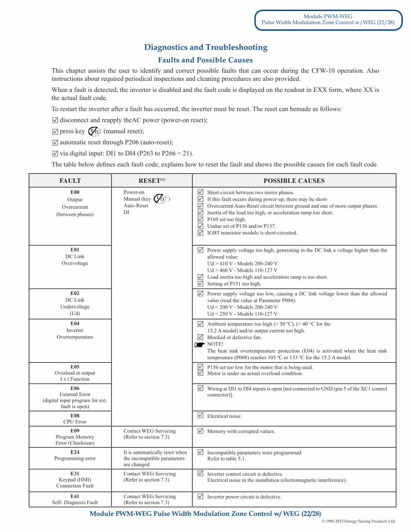
FAULT RESET(1) POSSIBLE CAUSESE00
Output Overcurrent
(between phases)
Power-onManual (key )Auto-ResetDI
Short-circuit between two motor phases.If this fault occurs during power-up, there may be short-Overcurrent Auto-Reset circuit between ground and one of more output phases. Inertia of the load too high, or acceleration ramp too short.P169 set too high.Undue set of P136 and/or P137.IGBT transistor module is short-circuited.
E01DC Link
Overvoltage
Power supply voltage too high, generating in the DC link a voltage higher than the allowed value:Ud > 410 V - Models 200-240 VUd > 460 V - Models 110-127 VLoad inertia too high and acceleration ramp is too short.Setting of P151 too high.
E02DC Link
Undervoltage(Ud)
Power supply voltage too low, causing a DC link voltage lower than the allowed value (read the value at Parameter P004):Ud < 200 V - Models 200-240 VUd < 250 V - Models 110-127 V
E04Inverter
Overtemperature
Ambient temperature too high (> 50 ºC), (> 40 °C for the15.2 A model) and/or output current too high.Blocked or defective fan.NOTE!The heat sink overtemperature protection (E04) is activated when the heat sink temperature (P008) reaches 103 ºC or 133 ºC for the 15.2 A model.
E05Overload at output
I x t Function
P156 set too low for the motor that is being used.Motor is under an actual overload condition.
E06External Error
(digital input program for ext. fault is open)
Wiring at DI1 to DI4 inputs is open [not connected to GND (pin 5 of the XC1 control connector)].
E08CPU Error
Electrical noise.
E09Program MemoryError (Checksum)
Contact WEG Servicing(Refer to section 7.3)
Memory with corrupted values.
E24Programming error
It is automatically reset when the incompatible parameters are changed
Incompatible parameters were programmedRefer to table 5.1.
E31Keypad (HMI)
Connection Fault
Contact WEG Servicing(Refer to section 7.3)
Inverter control circuit is defective.Electrical noise in the installation (electromagnetic interference).
E41Self- Diagnosis Fault
Contact WEG Servicing(Refer to section 7.3)
Inverter power circuit is defective.
Faults and Possible Causes This chapter assists the user to identify and correct possible faults that can occur during the CFW-10 operation. Also instructions about required periodical inspections and cleaning procedures are also provided.
When a fault is detected, the inverter is disabled and the fault code is displayed on the readout in EXX form, where XX is the actual fault code.
To restart the inverter after a fault has occurred, the inverter must be reset. The reset can bemade as follows:
disconnect and reapply theAC power (power-on reset);
press key (manual reset);
automatic reset through P206 (auto-reset);
via digital input: DI1 to DI4 (P263 to P266 = 21).
The table below defines each fault code, explains how to reset the fault and shows the possible causes for each fault code.
R
R
R
R
RRR
RRR
R
RR
R
R
R
Module PWM-WEGPulse Width Modulation Zone Control w/WEG (22/28)
Module PWM-WEG Pulse Width Modulation Zone Control w/ WEG (22/28)
RR
R
R
R
R
R
R
R
Diagnostics and Troubleshooting

© 1995-2012 Energy Saving Products Ltd.23
Note:(1) In case of E04 Fault due to inverter overtemperature, allow the inverter to cool down before trying to reset it.
NOTE!The faults act as follows:
E00 to E06: switches off the relay that has been programmed to “no fault”, disables the PWM pulses, displays the fault code on the display. Some data are saved on the EEPROM memory: keypad reference and EP (electronic potentiometer) (when the function “backup of the references” at P120 has been enabled), the occurred fault number, the status of the integrator of the I x t function (overcurrent).
E24: Indicates the fault code on the LED display.
E08, E09, E31 and E41: do not allow inverter operation (it is not possible to enable the inverter); the fault code is indicated on the LED display.
R
Problem Point to be Checked Corrective Action
Motor does not run Incorrect wiring 1.Check the power and the control connections. For example, the digital inputs DIx programmed for Start/Stop or General Enable or No External Fault must be connected to GND (pin 5 of the control connector XC1).
Analog reference 1.Check if the external signal is properly connected (if used).2.Check the status of the speed potentiometer (if used).
Incorrect programming 1.Check if the parameters are properly programmed for the application.
Fault 1.Check if the inverter has not been disabled due to detected fault condition (refer to table above).
Motor stall 1.Reduce the motor load.2.Increase P169 or P136/P137.
Motor speedoscillates
Loose connections 1.Disable the inverter, switch OFF the power supply and tighten all connections.
Defective speed potentiometer
1.Replace the defective speed potentiometer.
Variation of the external analog reference
1.Identify the cause of the variation.
Motor speed too high ortoo low
Programming error(reference limits)
1.Check if the contents of P133 (minimum frequency) and P134 (maximum frequency) are according to the motor and the application.
Signal of thereference control
1.Check the control signal level of the reference.2.Check the programming (gains and offset) at P234 to P236.
Motor nameplate 1.Check if the used motor meets the application requirements.
Display OFF Power supply 1.The power supply must be within the following ranges:200-240 V models: - Min: 170 V - Max: 264 V110-127 V models: - Min: 93 V - Max: 140 V
R
R
Module PWM-WEGPulse Width Modulation Zone Control w/WEG (23/28)
Module PWM-WEG Pulse Width Modulation Zone Control w/ WEG (23/28)
Faults and Possible Causes Cont’d

© 1995-2012 Energy Saving Products Ltd.
Model: _______________________
# of Outlets: ___________________
Ideal CFM Total: ________________
Programmed CFM Total: __________
#Location
IdealCFM
InitialFPM/CFM
Prgm’dFPM/CFM
#Location
IdealCFM
InitialFPM/CFM
Prgm’dFPM/CFM
1 26
2 27
3 28
4 29
5 30
6 31
7 32
8 33
9 34
10 35
11 36
12 37
13 38
14 39
15 40
16 41
17 42
18 43
19 44
20 45
21 46
22 47
23 48
24 49
25 50
Totals:
Average: (Total # of Vents Divided by # of Locations)
24
Module PWM-WEGPulse Width Modulation Zone Control w/WEG (24/28)
Module PWM-WEG Pulse Width Modulation Zone Control w/ WEG (24/28)
PWM Controller Input Sheets (Heating)

© 1995-2012 Energy Saving Products Ltd.25
Module PWM-WEGPulse Width Modulation Zone Control w/WEG (25/28)
Module PWM-WEG Pulse Width Modulation Zone Control w/ WEG (25/28)
Model: _______________________
# of Outlets: ___________________
Ideal CFM Total: ________________
Programmed CFM Total: __________
#Location
IdealCFM
InitialFPM/CFM
Prgm’dFPM/CFM
#Location
IdealCFM
InitialFPM/CFM
Prgm’dFPM/CFM
1 26
2 27
3 28
4 29
5 30
6 31
7 32
8 33
9 34
10 35
11 36
12 37
13 38
14 39
15 40
16 41
17 42
18 43
19 44
20 45
21 46
22 47
23 48
24 49
25 50
Totals:
Average: (Total # of Vents Divided by # of Locations)
PWM Controller Input Sheets (Cooling)

© 1995-2012 Energy Saving Products Ltd.26
Module PWM-WEGPulse Width Modulation Zone Control w/WEG (26/28)
Module PWM-WEG Pulse Width Modulation Zone Control w/ WEG (26/28)
#Location
IdealCFM
InitialFPM/CFM
Prgm’dFPM/CFM
#Location
IdealCFM
InitialFPM/CFM
Prgm’dFPM/CFM
1 26
2 27
3 28
4 29
5 30
6 31
7 32
8 33
9 34
10 35
11 36
12 37
13 38
14 39
15 40
16 41
17 42
18 43
19 44
20 45
21 46
22 47
23 48
24 49
25 50
Totals:
Average: (Total # of Vents Divided by # of Locations)
Model: _______________________
# of Outlets: ___________________
Ideal CFM Total: ________________
Programmed CFM Total: __________
PWM Controller Input Sheets (Constant Fan)

Energy Saving Products Ltd., established in 1983, manufactures the Hi-Velocity SystemsTM product line for residential, commercial and multi-family markets. Our facilities house Administration, Sales, Design, Manufacturing, as well as Research & Development complete with an in-house test lab. Energy Saving Products prides itself on Customer Service and provides design services and contractor support.
For all of your Heating, Cooling and Indoor Air Quality needs, the Hi-Velocity System is the right choice for you!
Phone: 780-453-2093 Fax: 780-453-1932
Toll Free: 1-888-652-2219HARDI
www.hi–velocity.com
Hi-Velocity HE Fan Coils, Green TechnologyBuild Smart, Breathe Easy
Small Duct Heating, Cooling and IAQ Systems