tm samil · pdf file06 do not disassemble the solarriver series inverter. it contains no...
TRANSCRIPT
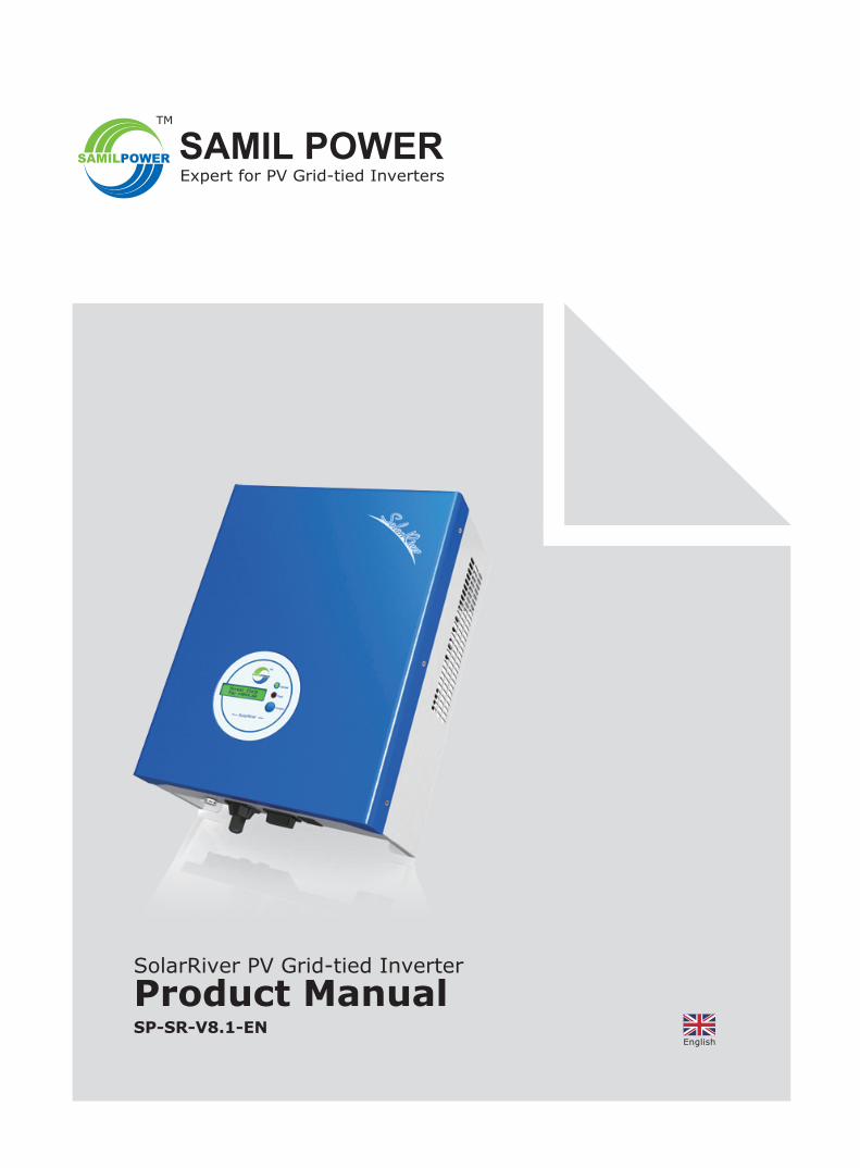
SP-SR-V8.1-EN
SolarRiver PV Grid-tied Inverter
Product Manual
SAMIL POWERExpert for PV Grid-tied Inverters
TM
English


Copyright Declaration
The copyright of this manual belongs to Samil Power Co., Ltd. Any corporation or individual should not plagiarize, partially copy or fully copy it (including software, etc.), and should not reproduce or distribute it in any form or by any means. All rights reserved.
Samil Power reserves the right of final interpretation. This manual is continuously updated based on user feedback. Please check our website www.samilpower.com for the latest version.
01
02
CONTENTS1 Notes ................................................................................................................................
1.1 Scope ...................................................................................................................................1.2 Target Group .........................................................................................................................1.3 Symbols Used ........................................................................................................................
2 Safety ...............................................................................................................................2.1 Appropriate Usage ..................................................................................................................2.2 Important Safety Instructions ..................................................................................................2.3 Explanation of Symbols ............................................................................................................
3 Introduction ......................................................................................................................3.1 Basic Features ........................................................................................................................3.2 Electrical block diagram ...........................................................................................................3.3 Dimensions and Weight ...........................................................................................................
4 Technical Data ...................................................................................................................4.1 Input (DC) ............................................................................................................................4.2 Output (AC) ...........................................................................................................................4.3 Efficiency, Safety and Protection ...............................................................................................4.4 General Data .........................................................................................................................
5 Function .............................................................................................................................
6 Installation ........................................................................................................................6.1 Packaging .............................................................................................................................6.2 Installation precaution ............................................................................................................6.3 Preparation ............................................................................................................................6.4 Installation Steps ...................................................................................................................6.5 Connections of PV Strings ........................................................................................................6.6 Inverter Start-up ....................................................................................................................
7 Operation ...........................................................................................................................7.1 Control Panel .........................................................................................................................7.2 Display Function ....................................................................................................................7.3 Display Information ................................................................................................................
8 Communication and Monitoring .........................................................................................8.1 Communication Interface .........................................................................................................8.2 Communication types .............................................................................................................
9 Troubleshooting ................................................................................................................9.1 Troubleshooting ......................................................................................................................9.2 Routine Maintenance ..............................................................................................................
10 Decommissioning ............................................................................................................ 10.1 Dismantling OF the Inverter ................................................................................................. 10.2 Packaging .......................................................................................................................... 10.3 Storage ............................................................................................................................. 10.4 Disposal ............................................................................................................................
11 Contact Samil Power .......................................................................................................
03030303
03030404
06060608
0909090910
10
11111213131519
19192022
242424
262627
2828282828
28
03
1 Notes
Danger!Danger indicates a hazardous situation, if not avoided, will result in death or serious injury.
1.1 Scope of Validity
2 Safety
2.1 Appropriate Usage
1.2 Target Group
This manual is to be read by qualified installer and PV system user. The tasks described in this manual must only be performed by qualified personnel.
Some symbols are used in this manual in order to ensure safety of personal and property. Please read the following symbols carefully.
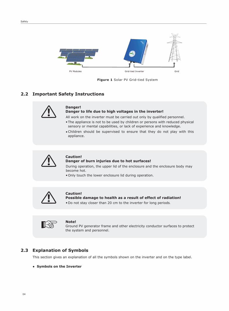
The SolarRiver Series is a Solar PV inverter which converts the DC current from a PV generator into AC current and feeds it into the public grid.
This manual is an integral part of the inverter, Please read the product manual carefully before installation, operation or maintenance. Keep this product manual for future reference.
This manual is an integral part of the inverter. Please read this manual carefully before installation, operation or maintenance and it safe for future reference.
SolarRiver 1100TL SolarRiver 1600TLSolarRiver 2300TL SolarRiver 3000TL SolarRiver 3300TLSolarRiver 3680TL SolarRiver 4400TL SolarRiver 5200TL
Please keep this manual where it will be accessible at all times.
1.3 Symbols Used
Warning!Warning indicates a hazardous situation, if not avoided, could result in death or serious injury.
Caution!Caution indicates a hazardous situation, if not avoided, could result in minor or moderate injury.
Note!Note provides tips that are valuable for the optimal operation of your product.
Notes & Safety
04
This section gives an explanation of all the symbols shown on the inverter and on the type label.
The appliance is not to be used by children or persons with reduced physical sensory or mental capabilities, or lack of experience and knowledge.
Children should be supervised to ensure that they do not play with this appliance.
2.2 Important Safety Instructions
2.3 Explanation of Symbols
Note!Ground PV generator frame and other electricity conductor surfaces to protect the system and personnel.
Safety
Figure 1 Solar PV Grid-tied System
•
•
All work on the inverter must be carried out only by qualified personnel.
Caution!Danger of burn injuries due to hot surfaces!
Danger!Danger to life due to high voltages in the inverter!
Only touch the lower enclosure lid during operation.•
During operation, the upper lid of the enclosure and the enclosure body may become hot.
Caution!Possible damage to health as a result of effect of radiation!
Do not stay closer than 20 cm to the inverter for long periods.•
● Symbols on the Inverter
PV Modules Grid-tied Inverter Grid

05
Symbol Explanation
5 min
Danger to life due to high voltages in the inverter!There is residual voltage in the inverter. The inverter requires 5 minutes to discharge. • Wait 5 minutes before you open the upper lid or the DC lid.
Beware of hot surface.The inverter can become hot during operation. Avoid contact during operation.
Danger of high voltagesDanger to life due to high voltages in the inverter!
Caution, risk of electric shock!Only authorized personnel is allowed to set the DIP switch.
● Symbols on the Type Label
● Important Safety Instructions
Symbol Explanation
CE mark.The inverter complies with the requirements of the applicable CE guidelines.
When using the product, please do follow information below to avoid fire, lightning or other personal injury:
Warning!Ensure input DC voltage ≤ the Max.DC voltage. Over voltage may cause permanent damage to the inverter or cause other damages which are not covered in the warranty! This chapter contains important safety and operating instructions. Read and keep this Manual for future reference.
Warning!Authorized service personnel must disconnect both AC and DC power from the SolarRiver Series inverter before attempting any maintenance or cleaning or working on any circuits connected to the SolarRiver Series inverter.The installation of inverter must fulfill wiring.
Before using the SolarRiver Series inverter, read all instructions and cautionary markings on the SolarRiver Series inverter, and all appropriate sections of this guide.
Use only accesories recommended or sold by Samil Power, otherwise may result in risk of fire, electric shock, or injury to persons.
To avoid risk of fire and electric shock, make sure that existing wiring is in good condition and cables used are not undersized. Do not operate the SolarRiver Series inverter with damaged or substandard wiring.
●
●
●
Safety
06
Do not disassemble the SolarRiver Series inverter. It contains no user-serviceable parts. See warranty for instructions on obtaining service. Attempting to service the SolarRiver Series inverter the user may result in risk of electric shock or fire and will void the warranty.
To reduce the risk of electric shock, authorized service personnel must disconnect both AC and DC power from the SolarRiver Series inverter before attempting any maintenance or cleaning or working on any circuits connected to the SolarRiver Series inverter. Turning off controls alone will not reduce this risk.
Keep away from flammable, explosive materials to avoid fire disaster.
The installation location should not be close to humid or corrosive substance.
To avoid electric shock , please do not disassemble the inverter as there are high-voltage capacitances installed inside the inverter. Fatal High-voltage will remain in the inverter for 5 minutes after its disconnection from grid or PV plant.
To reduce the chance of short-circuits, authorized service personnel must use insulated tools when installing or working with this equipment.
●
●
●
●
●
●
● ● ● ● ● ● ● ● ● ●
□□□□
3 Introduction
3.1 Basic Features
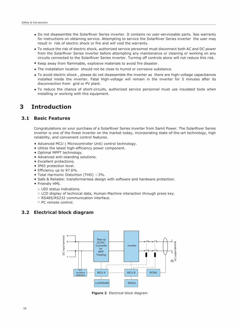
3.2 Electrical block diagram
Congratulations on your purchase of a SolarRiver Series inverter from Samil Power. The SolarRiver Series inverter is one of the finest inverter on the market today, incorporating state-of-the-art technology, high reliability, and convenient control features.
Advanced MCU ( Microcontroller Unit) control technology.Utilize the latest high-efficiency power component.Optimal MPPT technology.Advanced anti-islanding solutions.Excellent protections.IP65 protection level.Efficiency up to 97.6%.Total Harmonic Distortion (THD) <3%.Safe & Reliable: transformerless design with software and hardware protection. Friendly HMI.
LED status indications.LCD display of technical data, Human-Machine interaction through press key.RS485/RS232 communication interface.PC remote control.
+
--
+ L
N
PE AC
outp
utte
rmin
al
Step-upDC/DC
Converterfor
MPPTracking
Inverter
PVInsulationDetection
MCU A MCU B RCMU
LCD/RS485 RS232
DC
inpu
t ter
min
al
Figure 2 Electrical block diagram
Safety & Introduction

07
Introduction
● Terminals on the inverter
Caution!SF-SW. Risk of electric shock! Only authorized personnel is allowed to set the DIP switch.
RS232DC Input AC Output
Figure 3 Terminals of PV invertersSolarRiver 1100TL/SolarRiver 1600TL
Figure 4 Terminals of PV invertersSolarRiver 2300TL/SolarRiver 3000TL
Figure 5 Terminals of PV invertersSolarRiver 3300TL/SolarRiver 3680TL/SolarRiver 4400TL/SolarRiver 5200TL
RS485
RS232DC Input AC Output
SF-SW
RS485
RS232DC Input AC Output
SF-SW

08
Introduction
● Dimension
● Weight
3.3 Dimensions and Weight
Figure 6 SolarRiver 1100TL/SolarRiver 1600TL
Figure 7 SolarRiver 2300TL/SolarRiver 3000TL
Figure 8 SolarRiver 3300TL/SolarRiver 3680TL/SolarRiver 4400TL/SolarRiver 5200TL
Table 1 Weight in kilo grams, kg
Weight [kg]
Model
11.4
SolarRiver 1100TL
11.4
SolarRiver 1600TL
17.5
SolarRiver 2300TL
17.9
SolarRiver 3000TL
18.9
SolarRiver 3300TL
19.2
SolarRiver 3680TL
19.2
SolarRiver 4400TL
19.4
SolarRiver 5200TL
443m
m
347mm
328mm

Model
Max.DC power [W]
Max.DC voltage [V]
Max. input current [A]
Number of MPP trackers/ Strings per MPP trackers
MPPT voltage range (at rated powe) [V]
Shutdown voltage/ Start voltage
5200
26
4580
21
200-500
3480
17.5
1/2
3000
550
13.5
210-500
70/10075/100
2300
11
200-500
1600
9.7
160-425
1100
500
8.8
1/1
120-425
Model
AC rated power [W]
MAX. AC power [W]
Rated AC current [A]
Nominal AC voltage/ range [V]
AC grid frequency/ range [Hz]
Power factor (cosφ)
Total harmonic distortion (THDi) (at nominal power)
Model
Max. efficiency
Euro- efficiency
MPPT efficiency
Overvoltage / under-voltage protectionDC isolation imped-ance monitoring
4 Technical Data
4.1 Input (DC)
4.2 Output (AC)
4.3 Efficiency, Safety & Protection
SolarRiver 1100TL
SolarRiver 1600TL
SolarRiver 2300TL
SolarRiver 3000TL
SolarRiver 3300TL
4000
20
SolarRiver 3680TL
SolarRiver 4400TL
SolarRiver 5200TL
4600400030002600200015001000
5000440033002800220015001000
24221613.8118.35.5
SolarRiver 1100TL
SolarRiver 1600TL
SolarRiver2300TL
SolarRiver3000TL
SolarRiver3300TL
3680
3680
16
SolarRiver3680TL
SolarRiver4400TL
SolarRiver5200TL
97.6%97.6%97.4%97.0%96.8%96.8%96.6%
96.8%97.1%96.5%96.3%96.2%96.0%95.5%
99.9%
Yes
Yes
SolarRiver 1100TL
SolarRiver 1600TL
SolarRiver 2300TL
SolarRiver 3000TL
SolarRiver 3300TL
97.6%
97.1%
SolarRiver 3680TL
SolarRiver 4400TL
SolarRiver 5200TL
230 / 180~270*
50 / 47~52*
1
<3%
*Detailed parameter please see local grid standard.
Safety & Protection
09
Technical Data
Ground fault protection
Grid monitoring
Ground fault current monitoring
DC injection monitoring
Yes
Yes
Yes
Yes
Continued:
4.4 General Data
Model
Dimensions (W/H/D) [mm]
Weight [kg]
Operating temperature range [℃]
Topology
Degree of protection IP65
Internal consumption (night) [W]
Cooling concept
Noise (typical) [dB]
LCD display
Communication interfaces
Standard warranty [year]
SolarRiver 1100TL
SolarRiver 1600TL
SolarRiver 2300TL
SolarRiver 3000TL
SolarRiver 3300TL
SolarRiver 4400TL
SolarRiver 5200TL
285 / 385 / 145 328 / 450 / 161 347 / 443 / 180
11.4 11.4
Convection Fan
17.5 17.9 18.9 19.2 19.4
<28 <28
RS232 RS232 RS485 / RS232
<30
0
-20 °C ~ +60 (derating at 45 °C)
Backlight, 16*2 character LCD
Transformerless
5 years
<30 <30
SolarRiver 3680TL
19.2
<40 <40 <40
Bild 3 SolarLake Anschlussklemmen des Wechselrichters
5 FunctionOperation Mode
【Stand-by Mode】The standby mode means that the inverter is ready for operation but still not connected to the grid. In this mode, it will continue to check whether PV array has enough power to feedback into grid. When the inverter passes dump load test after startup, it will change from standby mode to Checking mode.
【Checking Mode】If inverter passes dump load test and no error/fault occurs, will start checking mode to deliver power.
【On-grid Mode】In this mode, SolarRiver series inverters convert PV array’s DC into AC and feedback into grid.
Caution!It is normal that the inverter decreases the output power in the condition of thermal protection, but if this occurs frequently the heat sink and the fan will need to be checked and the inverter may need to be shifted to a place with better air flow. If the fan is dirty it should be cleaned and if the output power decrease is caused by electricity issues, please ask for professional support.
10
Technical Data & Function
11
Installation
6 Installation
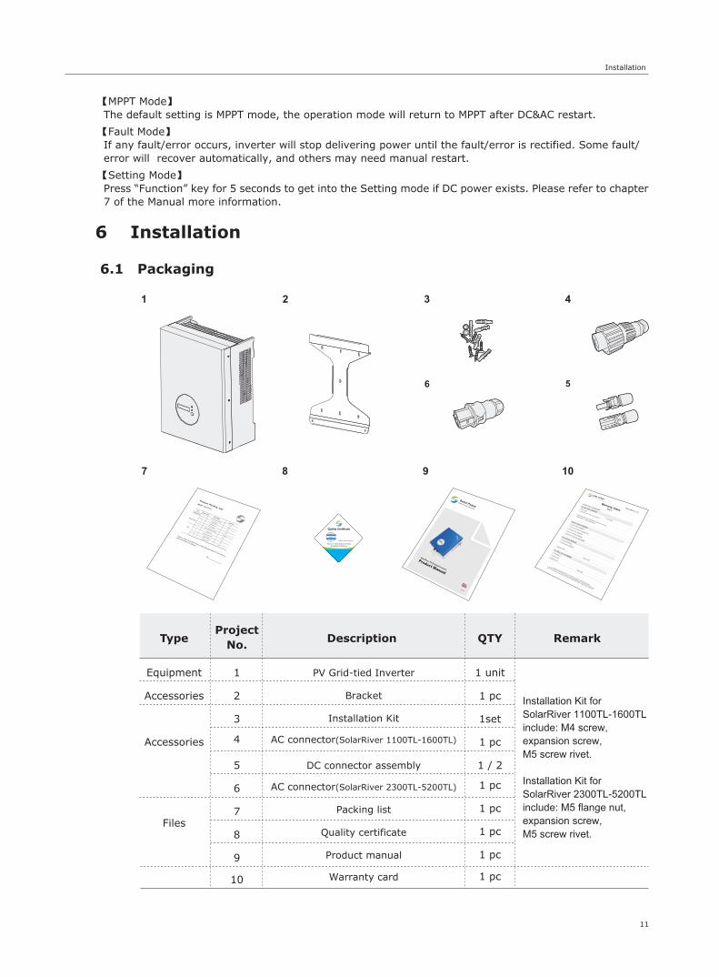
6.1 Packaging
Type Remark
Equipment
Installation Kit for SolarRiver 1100TL-1600TL include: M4 screw, expansion screw, M5 screw rivet.
Installation Kit for SolarRiver 2300TL-5200TL include: M5 flange nut, expansion screw, M5 screw rivet.
Accessories
Accessories
Files
Description
PV Grid-tied Inverter
Bracket
Installation Kit
AC connector(SolarRiver 2300TL-5200TL)
DC connector assembly
AC connector(SolarRiver 1100TL-1600TL)
Packing list
Product manual
Quality certificate
Warranty card
QTY
1 unit
1 pc
1set
1 pc
1 pc
1 / 2
1 pc
1 pc
1 pc
1 pc
ProjectNo.
1
2
3
4
5
6
7
8
9
10
【MPPT Mode】The default setting is MPPT mode, the operation mode will return to MPPT after DC&AC restart.
【Fault Mode】 If any fault/error occurs, inverter will stop delivering power until the fault/error is rectified. Some fault/error will recover automatically, and others may need manual restart.
【Setting Mode】Press “Function” key for 5 seconds to get into the Setting mode if DC power exists. Please refer to chapter 7 of the Manual more information.
6
English
FQCPASS
01

12
Installation
SolarRiver 1100TL~1600TL Inverter Backboard
SolarRiver 2300TL~5200TL Inverter Backboard
Warning!Ensure that the DC side is not charged before installation or maintenance. If the inverter is powered the capacitors will be charged if after the inverter is turned off,hence it is to wait for 5 minutes to ensure that the capacitors are discharged.
Note!Inverters must be installed by qualified personnel only .
6.2 Pre installation precautions
Check the location where inverter is to be installed to ensure the following.
The ambient temperature is within the operation range ( -20°C to +60°C -4°F to +140°F ). The altitude is less than 2,000 m. Not prone to be damaged by sea water.Not close to corrosive gas or liquid (for example, locations where chemicals are processed or lots of poultry is fed).Not exposed to direct sunlight. Not prone to be flooded snowed in.Ensure good ventilation and low humidity.Not exposed to steam, vapor, or water.
● ● ● ●
● ● ● ●
160mm 160mm
60mm 60mm
167.5
mm
192m
m
120m
m130m
m
104.5mm 104.5mm
25.5mm 25.5mm
85m
m85m
m
126.6
mm
13
Installation
Step1: Drill holes in the wall with drill machine according to the size of bracket. Drill straight into the wall do not shake the drill to avoid damage to the wall. Depth of the holes should be about 30mm and should be the same in all the holes. After removing dust from the holes, measure the net depth of the holes. If the depth is more than 33mm or less than 27mm, the expansion pipes can not be properly installed.
Position Min. clearance
Side
Top
Bottom
Front
30cm
30cm
30cm
10cm
Table 2 Minimum clearance needed
6.3 Preparation
6.4 Installation Steps
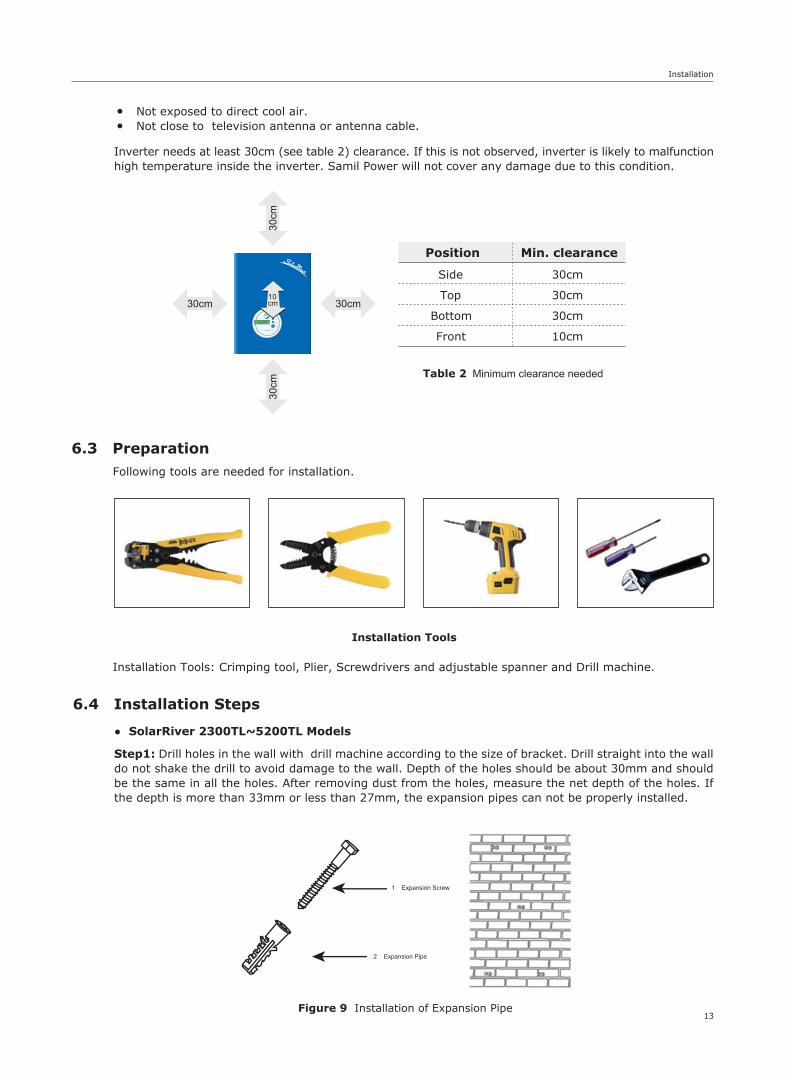
Following tools are needed for installation.
Installation Tools: Crimping tool, Plier, Screwdrivers and adjustable spanner and Drill machine.
Installation Tools
Inverter needs at least 30cm (see table 2) clearance. If this is not observed, inverter is likely to malfunctionhigh temperature inside the inverter. Samil Power will not cover any damage due to this condition.
● ●
Not exposed to direct cool air.Not close to television antenna or antenna cable.
● SolarRiver 2300TL~5200TL Models
Figure 9 Installation of Expansion Pipe
1 Expansion Screw
2 Expansion Pipe
14
Installation
Step3Step2
Step5Step4
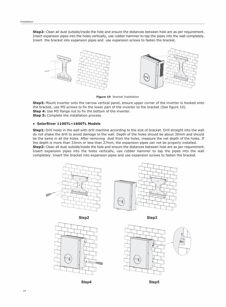
Step2: Clean all dust outside/inside the hole and ensure the distances between hole are as per requirement.Insert expansion pipes into the holes vertically, use rubber hammer to tap the pipes into the wall completely.Insert the bracket into expansion pipes and use expansion screws to fasten the bracket.
Step3: Mount inverter onto the narrow vertical panel, ensure upper corner of the inverter is hooked onto the bracket, use M5 screws to fix the lower part of the inverter to the bracket (See figure 10).Step 4: Use M5 flange nut to fix the bottom of the inverter.Step 5: Complete the installation process.
Step1: Drill holes in the wall with drill machine according to the size of bracket. Drill straight into the wall do not shake the drill to avoid damage to the wall. Depth of the holes should be about 30mm and should be the same in all the holes. After removing dust from the holes, measure the net depth of the holes. If the depth is more than 33mm or less than 27mm, the expansion pipes can not be properly installed.Step2: Clean all dust outside/inside the hole and ensure the distances between hole are as per requirement.Insert expansion pipes into the holes vertically, use rubber hammer to tap the pipes into the wall completely. Insert the bracket into expansion pipes and use expansion screws to fasten the bracket.
Figure 10 Bracket Installation
● SolarRiver 1100TL~1600TL Models
Installation
6.5 Connections of the PV power system
Step3: Use the bracket to install the inverter onto the narrow vertical panel (or wall). Ensure the upper corner of inverter is attached onto the bracket.Step4: Make sure the bracket and the inverter’s right side screw hole are in line and matching well, fix the screw into the hole and screw into the inverter tightly. Step5: If necessary lock the inverter and the bracket with padlock (not included) for safety.
● PV String
SolarRiver inverters 3300TL, 4400TL and 5200TL have facility to connect two strings of PV moduleswhile the other models can only take one module string. Use only PV modules with excellent performance and reliable quality. Open-circuit voltage of modules connected in series should be <Max. DC input voltage of the inverters (Ref Table 3) and the operating voltage at all times should be within the MPPT voltage range.
Only use good quality PV cables to connect modules to inverter. Normally the voltage drop between modulesand inverter could be about 1-2%. Hence inverter should be installed as close to the PV module as possibleto reduce cable losses.
Table 3 Max. DC Voltage of inverters
Model
Max. DC voltage
SolarRiver 1100TL
SolarRiver 1600TL
SolarRiver 2300TL
SolarRiver 3000TL
SolarRiver 3300TL
SolarRiver 3680TL
SolarRiver 4400TL
SolarRiver 5200TL
500V 550V
15
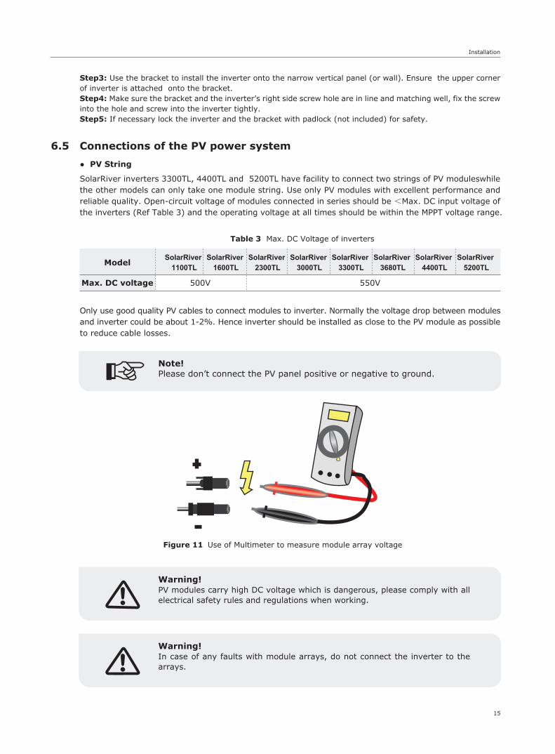
Note!Please don’t connect the PV panel positive or negative to ground.
Figure 11 Use of Multimeter to measure module array voltage
Warning!PV modules carry high DC voltage which is dangerous, please comply with all electrical safety rules and regulations when working.
Warning!In case of any faults with module arrays, do not connect the inverter to the arrays.
16
Installation
Note!Need not connect the input terminal to optimizer.
● AC Output
SolarRiver series inverters are designed for single phase grid. Operating AC voltage range from 180V to 260V (200V-270V for Australia) and the typical frequency is 50Hz. Other operating parameters should comply with local public grid regulations.
MCB with rated fault current of 30 mA≤Ifn≤300 mA should be installed between inverter and grid. No load should be connected directly with the inverter.
Table 4 Cable and MCB Requirement
Model
Cable (Cu)
MCB
SolarRiver1100TL
1.5mm²
10A
SolarRiver1600TL
2.5mm²
16A
SolarRiver2300TL
4mm²
20A
SolarRiver3000TL
4mm²
20A
SolarRiver3300TL
4mm²
25A
SolarRiver3680TL
4mm²
25A
SolarRiver4400TL
4mm²
25A
SolarRiver5200TL
4mm²
32A
Figure 13 AC Cable Loss for SolarRiver 3300TL
Length
0.0%
0.2%
0.4%
0.6%
0.8%
1.0%
1.2%
1.4%
Loss
0m 10m 20m 30m 40m 50m 60m 70m 80m 90m 100m
2.5mm2
4.0mm2
10.0mm2
6.0mm2
8.0mm2
SolarRiver inverters come with good quality IP66 AC connector. Please refer to information below to make correct AC connection.
Impedance of the AC connection should be less than 2Ω. To ensure anti-islanding function PV cable should ensure power loss to be <1% of nominal power. Also AC cable between inverter and connection point should be less than 150m. Chart below provides relationship between AC cable length and cross section with losses.
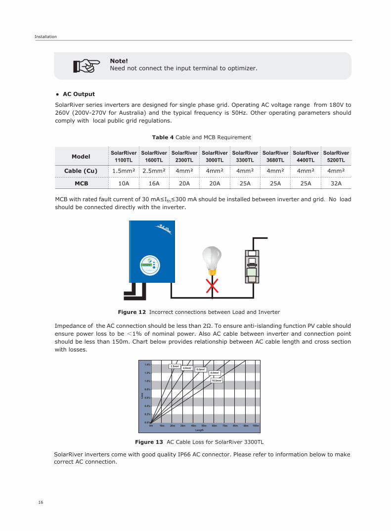
Figure 12 Incorrect connections between Load and Inverter
17
Installation
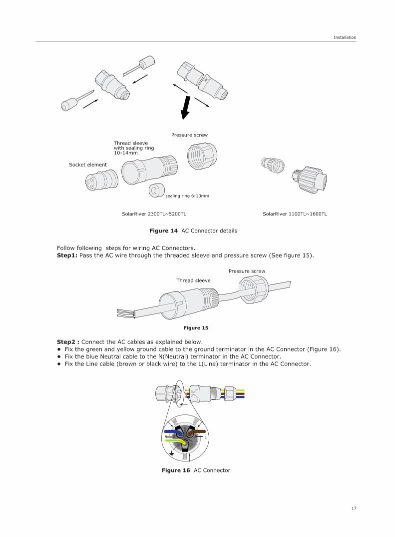
Figure 14 AC Connector details
SolarRiver 2300TL~5200TL SolarRiver 1100TL~1600TL
Socket element
Thread sleevewith sealing ring10-14mm
sealing ring 6-10mm
Pressure screw
Follow following steps for wiring AC Connectors.Step1: Pass the AC wire through the threaded sleeve and pressure screw (See figure 15).
Step2 : Connect the AC cables as explained below.• Fix the green and yellow ground cable to the ground terminator in the AC Connector (Figure 16).• Fix the blue Neutral cable to the N(Neutral) terminator in the AC Connector.• Fix the Line cable (brown or black wire) to the L(Line) terminator in the AC Connector.
Figure 15
Figure 16 AC Connector
Thread sleeve
Pressure screw
18
Installation
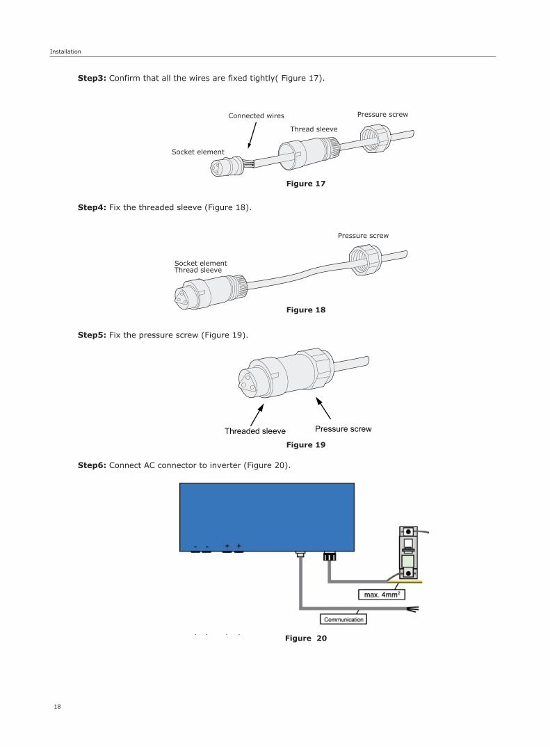
Step3: Confirm that all the wires are fixed tightly( Figure 17).
Step4: Fix the threaded sleeve (Figure 18).
Figure 17
Thread sleeve
Socket element
Pressure screwConnected wires
Figure 18
Socket element Thread sleeve
Pressure screw
Figure 20
Figure 19
Step5: Fix the pressure screw (Figure 19).
Step6: Connect AC connector to inverter (Figure 20).
Threaded sleeve Pressure screw

6.6 Inverter Start-up
• Only start inverter after checking following
• Starting inverter
a. Make sure all the DC and AC breakers and Isolators are in off position.b. AC cable from inverter to connection point is done correct.c. All PV panels are connected to inverter correctly,Unused DC connectors should be sealed using covers provided.
a. Turn ON AC MCB.b. Turn ON DC Isolator and then AC Isolator.c. Inverter will start up automatically when PV arrays generates enough energy. Inverter goes through the following three stages during normal start-up.
Waiting: Inverter is waiting / checking PV arrays output DC voltage to be with adequate .
Checking: Inverter checks AC grid conditions automatically when DC input voltage exceeds Start-up voltage. Inverter then goes through the start-up count down.
Normal: Inverter begins to operate normally with green light ON and feed energy to grid, LCD displays present output power. Inverter will stop feeding power to grid when PVoutput is not enough for normal operation.
Note!If inverter shows “Fault” status, please refer to Part 9.
19
Installation & Operation
7 Operation
7.1 Control Panel
Figure 21 Control Panel
Normal (green):The inverter is working in normal state.Fault (red):The system is in fault state.Function key:To check the operating parameters, for details, see section 7.2.

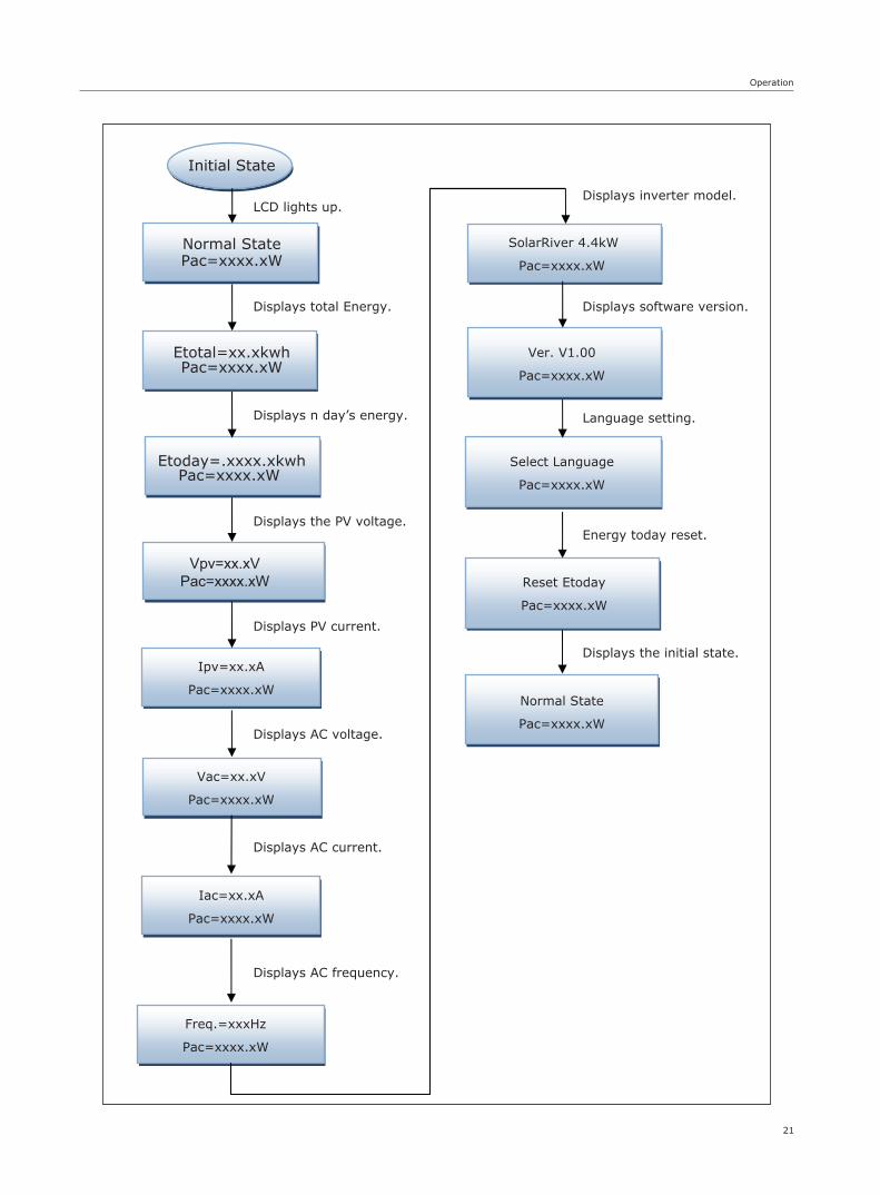
7.2 Display FunctionThe function key is used to set the LCD. It can alternate between different parameters and languages.
20
Operation
Display on normal operation
Waiting
Pac=x.xW
Checking 180sPac=x.xW
Normal State
Pac=x.xW
When the PV voltage>150V, Inverter willchange into “Normal State” modeafter 180 second start-up time.
Inverter will change into standbymode when 100V<the dc input <150V.
SolarRiver 4400TLPac=x.xW
Use Function Key to checkand
set inverter parameters
21
Operation
Normal State Pac=xxxx.xW
Etotal=xx.xkwh Pac=xxxx.xW
Etoday=.xxxx.xkwhPac=xxxx.xW
Ipv=xx.xA
Pac=xxxx.xW
Vac=xx.xV
Pac=xxxx.xW
Iac=xx.xA
Pac=xxxx.xW
Freq.=xxxHz
Pac=xxxx.xW
SolarRiver 4.4kW
Pac=xxxx.xW
Select Language
Pac=xxxx.xW
Initial State
Normal State
Pac=xxxx.xW
Ver. V1.00
Pac=xxxx.xW
Displays AC voltage.
Displays PV current.
Reset Etoday
Displays AC current.
Displays inverter model.
Displays n day’s energy.
Displays total Energy.
LCD lights up.
Displays the PV voltage.
Displays AC frequency.
Vpv=xx.xVPac=xxxx.xW
Language setting.
Displays software version.
Energy today reset.
Displays the initial state.
Pac=xxxx.xW
22
Operation
Lockup function as below: Set language as below:
Select language
Pac=xxxx.xW
Udc=xx.xV
Pac=xxxx.xW
Lock
Pac=xxxx.x
Udc=xx.xV
Pac=xxxx.xW
Idc=xx.xA
Pac=xxxx.xW
English
Pac=xxxx.xW
Normal State
Pac=xxxx.xW
Press and hold the Function Key tochange language
After a brief period of inactivity, the
display returns to “Normal State”
Press the Function key 10 times,
it will display the language setting.
(Press Function key to check data will go back to initial state after 10s of inactivity)
Press the Function key, it will
go to next state.
Press the Function key for 5
seconds, it will be locked.
Normal State
Pac=xxxx.xW
7.3 Display information
Operating State Information Display
Checking Parameters
Description
Working Condition
Power Off No display DC input voltage<70V,inverter stops working
Initialization& Waiting Waiting 70V< DC Input voltage≤150V in standby mode
Checking Checking Input voltage >150V in grid checking mode
Normal State Normal state Inverter is working in grid-tied mode
Flash Flash Upgrading software
Table 5 Display Information
Real-time Power Pac=xxxxW Real-time output power
Total energygeneration
Etotal=xxxxkWh Total energy generated
Operation
23
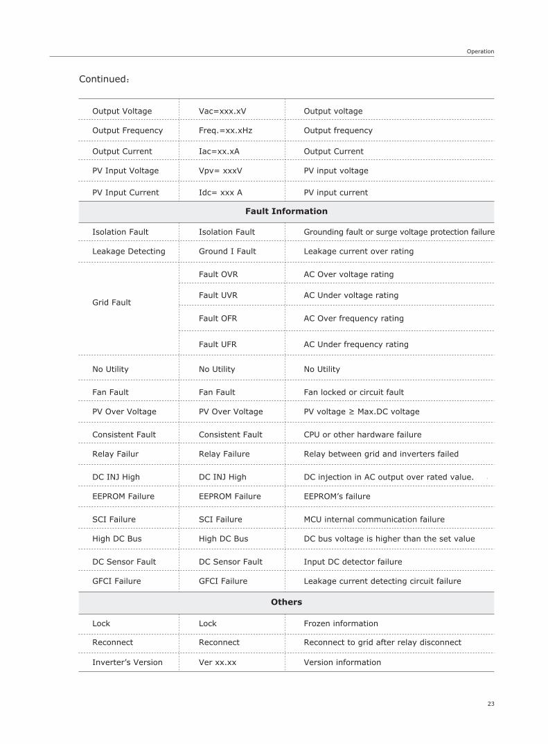
Fault Information
Others
Output Voltage Vac=xxx.xV
Output Frequency Freq.=xx.xHz
Output Current Iac=xx.xA
PV Input Voltage Vpv= xxxV
PV Input Current Idc= xxx A
Isolation Fault Isolation Fault
Leakage Detecting Ground I Fault
Grid Fault
Fault OVR
Fault UVR
Fault OFR
Fault UFR
No Utility No Utility
Fan Fault Fan Fault
PV Over Voltage PV Over Voltage
Consistent Fault Consistent Fault
Relay Failur Relay Failure
DC INJ High DC INJ High
EEPROM Failure EEPROM Failure
SCI Failure SCI Failure
High DC Bus High DC Bus
DC Sensor Fault DC Sensor Fault
GFCI Failure GFCI Failure
Lock Lock
Reconnect Reconnect
Inverter’s Version Ver xx.xx
Output voltage
Output frequency
Output Current
PV input voltage
PV input current
Grounding fault or surge voltage protection failure
Leakage current over rating
AC Over voltage rating
AC Under voltage rating
AC Over frequency rating
AC Under frequency rating
No Utility
Fan locked or circuit fault
PV voltage ≥ Max.DC voltage
CPU or other hardware failure
Relay between grid and inverters failed
DC injection in AC output over rated value.
EEPROM’s failure
MCU internal communication failure
DC bus voltage is higher than the set value
Input DC detector failure
Leakage current detecting circuit failure
Frozen information
Reconnect to grid after relay disconnect
Version information
Continued:
Communication and Monitoring
24
8 Communication and Monitoring
8.1 Communication Interface
8.2 Communication types
SolarRiver inverters have communication interface RS485 and /or RS232 depending on model. Output voltage,current, frequency, fault information, etc., can be delivered to a PC or other monitoring equipment via the RS485/RS232.
SolarRiver inverters come with one or both of the following types communication facility depending on model.
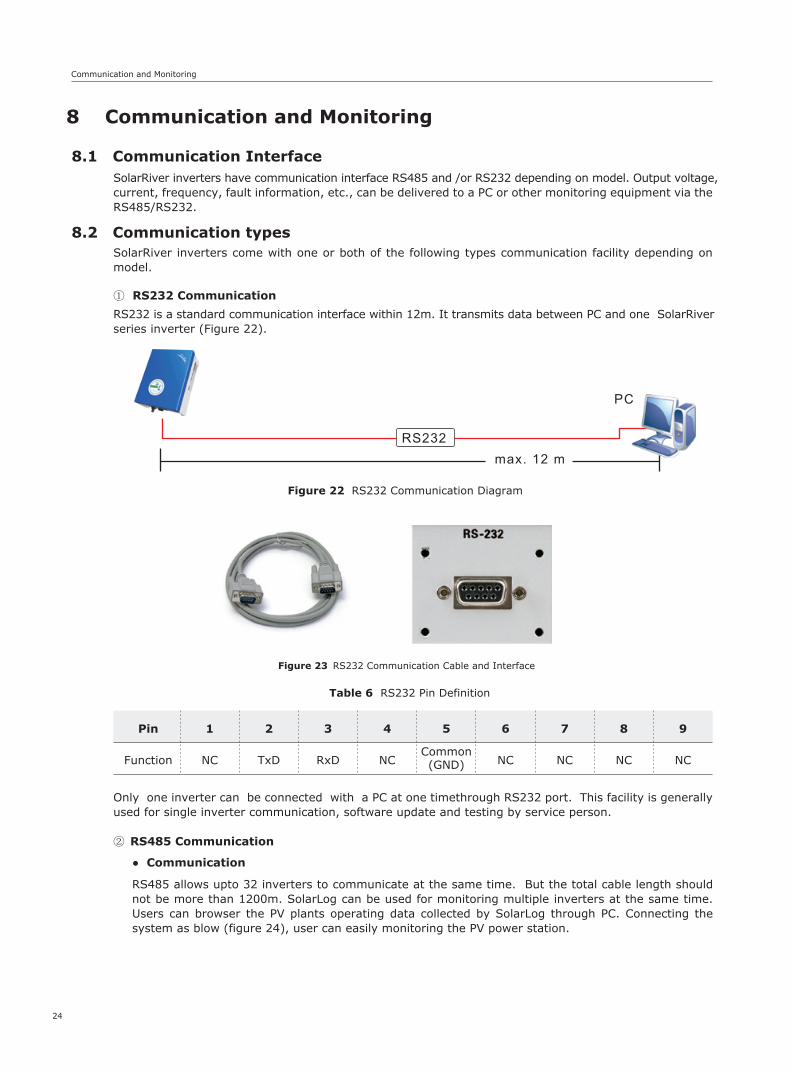
RS232 is a standard communication interface within 12m. It transmits data between PC and one SolarRiverseries inverter (Figure 22).
Only one inverter can be connected with a PC at one timethrough RS232 port. This facility is generally used for single inverter communication, software update and testing by service person.
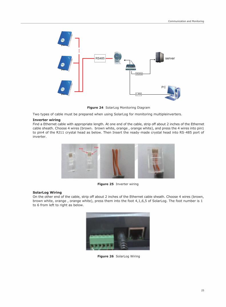
RS485 allows upto 32 inverters to communicate at the same time. But the total cable length should not be more than 1200m. SolarLog can be used for monitoring multiple inverters at the same time. Users can browser the PV plants operating data collected by SolarLog through PC. Connecting the system as blow (figure 24), user can easily monitoring the PV power station.
① RS232 Communication
② RS485 Communication
Figure 23 RS232 Communication Cable and Interface
Table 6 RS232 Pin Definition
Pin
Function
1
NC
2
TxD
3
RxD
4
NC
5
Common(GND)
6
NC
7
NC
8
NC
9
NC
● Communication
Figure 22 RS232 Communication Diagram
Communication and Monitoring
25
Figure 24 SolarLog Monitoring Diagram
Figure 25 Inverter wiring
Figure 26 SolarLog Wiring
Two types of cable must be prepared when using SolarLog for monitoring multipleinverters.
Inverter wiringFind a Ethernet cable with appropriate length. At one end of the cable, strip off about 2 inches of the Ethernetcable sheath. Choose 4 wires (brown,brown white, orange , orange white), and press the 4 wires into pin1 to pin4 of the RJ11 crystal head as below. Then Insert the ready-made crystal head into RS-485 port of inverter.
SolarLog WiringOn the other end of the cable, strip off about 2 inches of the Ethernet cable sheath. Choose 4 wires (brown,brown white, orange , orange white), press them into the foot 4,1,6,5 of SolarLog. The foot number is 1 to 6 from left to right as below.
server
Router
Troubleshooting
26
9 Troubleshooting
9.1 Troubleshooting
This section contains information and procedures for solving possible problems on SolarRiver series inverters, and provides troubleshooting tips to identify and solve most problems.
This section will help narrow down the source of any problems which you may encounter. Please read the following troubleshooting steps.
Contact installer or Samil Power Customer Service for further assistance. Please be prepared to describe details of the system installation and also provide the model and serial number of the inverter.
Check the warning or fault messages on the System Control Panel or Fault codes on the inverter information panel. If a message is displayed, record it before doing anything further.
Attempt the solution indicated in Table 7.
If the inverter information panel is not displaying a Fault light during a fault condition, check the following to make sure that the installation allows proper operation of the unit.
— Is the inverter located in a clean, dry, adequately ventilated place?
— Is the DC Isolator in ON position?
— Are the cables adequately sized and short enough?
— Are the input and output connections and wiring in good condition?
— Are the configurations settings correct for the particular installation?
— Are the display panel and the communications cable properly connected and undamaged?
●
●
●
Table 7 Troubleshooting tips
Faults Diagnosis and Solutions
Grid Fault - Wait for some time to allow grid supply to stabilize for inverter to go back to normal working state.- Making sure that grid voltage and frequency complies with standards.- Seek help from installer.
No Utility
PV Over Voltage
- No grid supply.- Check grid connection like cables , interface, etc.- Check grid usability.- Seek help from installer.
- Check the panel’s open-circuit voltage to be less than Max.DC voltage.- If PV open circuit voltage is higher consider rewiring modules to get voltage under limits.
DC INJ High - Wait for a minute to see if DC injection returns to normal.- If fault persists, contact Samil Power for assistance.
SCI Failure - Disconnect PV +ve and –ve input, and re-connect after a short break.- If fault persists, contact Samil Power for assistance.
Isolation Fault - Check the impedance between PV (+)、PV (-) and ground. For SolarRiver 2300TL~SolarRiver 5200TL >1Mohm .- Contact Samil Power if impedance value is not big enough.
Consistent Fault - Disconnect PV +ve and –ve input, and re-connect after a short break.- If fault persists, contact Samil Power for assistance.
Troubleshooting
27
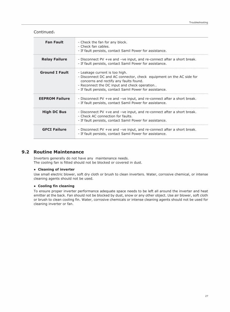
Continued:
Fan Fault - Check the fan for any block.- Check fan cables.- If fault persists, contact Samil Power for assistance.
High DC Bus - Disconnect PV +ve and –ve input, and re-connect after a short break.- Check AC connection for faults.- If fault persists, contact Samil Power for assistance.
GFCI Failure - Disconnect PV +ve and –ve input, and re-connect after a short break.- If fault persists, contact Samil Power for assistance.
Relay Failure - Disconnect PV +ve and –ve input, and re-connect after a short break.- If fault persists, contact Samil Power for assistance.
EEPROM Failure - Disconnect PV +ve and –ve input, and re-connect after a short break.- If fault persists, contact Samil Power for assistance.
Ground I Fault - Leakage current is too high.- Disconnect DC and AC connector, check equipment on the AC side for concerns and rectify any faults found.- Reconnect the DC input and check operation..- If fault persists, contact Samil Power for assistance.
9.2 Routine MaintenanceInverters generally do not have any maintenance needs. The cooling fan is fitted should not be blocked or covered in dust.
Use small electric blower, soft dry cloth or brush to clean inverters. Water, corrosive chemical, or intense cleaning agents should not be used.
To ensure proper inverter performance adequate space needs to be left all around the inverter and heat emitter at the back. Fan should not be blocked by dust, snow or any other object. Use air blower, soft cloth or brush to clean cooling fin. Water, corrosive chemicals or intense cleaning agents should not be used for cleaning inverter or fan.
● Cleaning of inverter
● Cooling fin cleaning
Decommissioning & Contacting Samil Power
28
10.1 Dismantling the Inverter
10.2 Packaging
10.3 Storage
10.4 Disposal
If possible, pack the inverter in the original packaging.If original packaging is not available, use an equivalent carton that meets the following requirements.
Store the inverter in dry place where ambient temperature is always between -20 °C ~ +60 °C.
Return faulty inverters to Samil Power for repair or recyle.
10 Decommissioning
● Disconnect the inverter from DC Input and AC output.
● Remove all connection cables from the inverter.
● Remove the inverter from the bracket.
● Suitable for loads more than 25 kg.
● With handle.
● Can be fully closed.
If you have any questions about SolarRiver series inverter, please call service support hotline: +86 510 83593131. Please have the following information ready when contacting Samil Power.
11 Contacting Samil Power
a. Inverter Model.
b. Inverter Serial No..
c. Communication Method.
d. PV modules make, model and units.


SAMIL POWER CO., LTD.Sales and Service CenterAdd: No.52, Huigu Innovation Park , Huishan District, Wuxi Jiangsu Province, 214174 P.R.CTel: +86 510 8359 3132Fax: +86 510 8181 9678http://www.samilpower.com
FactoryAdd: No.6, Xuefengshan Road, Suqian High-tech Industrial Development Zone, Jiangsu Province, P.R.China. 223800Tel: +86 527 88754666Fax: +86 527 84453877
Samil Power Service Contact InformationSamil Power Service AustraliaSupport Center : +61285203242/1300 134 793E-mail: [email protected]
Samil Power Service DeutschlandSupport Center : +498912140704 E-mail: [email protected]
Samil Power Service ItaliaSupport Center : +390260063040E-mail: [email protected]
Samil Power Service United KingdomSupport Center : +441184029490E-mail: [email protected]
Samil Power Service Netherlands Support Center : +31207018205E-mail: [email protected]
Samil Power Service GlobalSupport Center : +86 510 83593132 ext. 8010E-mail: [email protected]