tm - policy and orderspolicyandorders.cw.bc.ca/resource-gallery/documents/transfusion... · |...
TRANSCRIPT

OPERATOR’S MANUALP/N 4533708GB Rev. 008
lTM
s

ii | Operator’s Manual

Copyright
Level 1® H-1200 Fast Flow Fluid WarmerPart Number: 4533708GB Rev. 008 (2010-02)
This revision supercedes all previous revisions.
Under copyright laws, this manual may not be reproduced in any form, inwhole, or in part, without prior written permission of Smiths Medical ASD,Inc. (Smiths Medical).
Smiths Medical and Level 1 design marks and Level 1 are trademarks of theSmiths Medical family of companies. The symbol ® indicates the trademark isregistered in the U. S. Patent and Trademark office and certain othercountries. All other names and marks mentioned are the tradenames,trademarks, or service marks of their respective owners.
Every effort has been made to ensure that the information in this manual isaccurate and details provided are correct at the time of printing. The company, however, reserves the right to improve the equipment shown.
Mention of third-party products is for informational purposes only andconstitutes neither an endorsement nor a recommendation. Smiths Medicalassumes no responsibility with regard to the performance or use of theseproducts.
For further information, please call your local Smiths Medical distributor orSmiths Medical direct at 1-800-258-5361 or +1-781-878-8011.
©2010 Smiths Medical family of companies.All rights reserved.
The products described are covered by one or more of the following U.S.Patent Nos. 5,063,994; 5,097,898; 5,417,274; 5,512,043 and 6,575,935; andcounterpart foreign patent(s); other patent(s) pending.
Manufactured in the U.S.A.
iii| Operator’s Manual
C o p y r i g h t

| Operator’s Manual
Contents1 About this Manual 1
2 Description 3
3 Indications for Use 4
4 Important Safety Information 5Contraindications 5Warnings 5Cautions 8
5 Out of the Box—Assembly 9Step 1 Verify Components 10Step 2 Assemble I.V. Pole to Warming Unit 11Step 3 Install the Pressure Chambers 12Step 4 Attach the I.V. Bag Hanger 13Step 5 Disinfect the Recirculating Solution Reservoir 13Step 6 Preliminary Preparation 14Step 7 Connect the Pneumatic Tubing 14Step 8 Install the Level 1® H-31, Version B, Air Detector/
Clamp 15Step 9 Perform Electrical Safety Tests 17
6 Principle of Operation 19Fluid Warming 19Pressurized Fluid Delivery 19Air Detection/Clamping 19F-50 Gas Vent/Filter Assembly 20
7 Controls and Displays 21Fluid Warmer Power and Alarm Test Panel 22Fluid Warmer Display Panel 23Air Detector/Clamp Control Panel and Alarms 24Pressure Chamber Control Panel 25Interlocks 26
8 Operation 29Modes Of Operation 30
OFF Mode 30ON/ Automatic Operation Mode for Fluid Warmer 30Alarm Test Mode 31Over Temperature Test Mode 31Temperature Display 31Check Disposables Mode 32Add Recirculating Solution Mode 32Over Temperature Alarm Mode 33Power ON Test for the Air Detector/Clamp 33Automatic Operation Air Detector/Clamp 34Check Tubing Mode 34Air Detected/Clamped Mode 35Pressure Display 35Pressurized Mode 35Unpressurized Mode 36
C o n t e n t s
iv

| Operator’s Manual
9 Operating Instructions 37Warnings 379.1 Set Up for Use 38
A Install Disposable Administration Set 38B Prime the Disposable Administration Set 41C Prime the Patient Line 42D Test the Audible and Visual Alarms 43E Test the Air Detector/Clamp 44
9.2 Use of the Fluid Warmer 46Step 1 Load the Pressure Chambers 46Step 2 Pressurize the Pressure Chambers 47Step 3 Make Patient Connection 48Step 4 Replace the Gas Vent/Filter Assembly 48Step 5 Change the Fluid Bag 48
9.3 Replace the Gas Vent/Filter Assembly 489.4 Activated Alarms 499.5 After Use 51
10 Troubleshooting 52General Troubleshooting Guide 52Slow Flow Rate Troubleshooting Guide 53
11 Testing 54Add Recirculating Solution Alarm 54Check Disposables Alarm 54Over Temperature Test 55Fluid Warmer Alarm Signal Test 55Performance Testing 56
Cold Start Test 56Calibration Test 56Alternative Calibration Test 56Calibration Test with DSTA 40 56Proper Calibration of Recirculating Solution Temperature 57
Periodic Electrical Testing 58Earth Leakage 58Ground Continuity 58
12 Maintenance 59Maintenance Performed Prior to Every Use 59
Clean the Exterior 59General Inspection 60
Maintenance Performed Every 30 Days 61Lubricate O Ring Seals 61Change Recirculating Solution with Distilled Water 61
Maintenance Performed Every 12 Months 61Disinfect the Reservoir 61Change Recirculating Solution with 0.3% HydrogenPeroxide/Distilled Water Solution 62Change O Rings 62Clean Fan Filter 62Inspect Air Detector/Clamp 63Testing Fluid Warmer Operation 63
Maintenance and Calibration Log 64Scheduled Maintenance and Calibration Checklist 64
C o n t e n t s
v

| Operator’s Manualvi
C o n t e n t s
13 Limited Warranty 65
14 Service 67Warranty Service 67Non-Warranty Work 67Additional Documentation 67Disposal Information 68Service Contacts 68
15 Specifications 69System Specifications 69
Physical 69Environmental 69Thermal 69Electrical 69
Electromagnetic Environment Recommendations 70Disposable Administration Set Specifications 70
DI 50 70D/DI 60HL and D/DI 65HL 70D/DI 70 and D/DI 75 71D/DI 100 and D/DI 150 71D/DI 300 and D/DI 350 71
16 Symbols 72
Index 75

S E C T I O N 1
About this Manual
This Operator’s Manual describes the set-up, use, and maintenance of:
• Level 1® H-1200 Fast Flow Fluid Warmer • Level 1® H-1000 Fast Flow Fluid Warmer with H-2 Pressure
Chambers (H-1025)• Level 1® H-1000 Fast Flow Fluid Warmer with H-2 Pressure
Chambers and H-31, Version B, Air Detector/Clamp
The manual is intended for use by individuals trained in thehealthcare and biomedical professions.
This operator’s manual is also for users of the H-1000 Fast Flow Fluid Warmer. All references to the “Level 1® H-1200 Fast Flow FluidWarmer” apply to the H-1000 Fast Flow Fluid Warmer except whereindicated by the symbols defined in the following table.
Symbol Description
Appears in the margin to identify informationthat only applies to the H-1200 Fluid Warmerand the H-1000 Fluid Warmer equipped with theH-31, Version B, Air Detector/ClampAppears in the margin to identify informationthat only applies to the H-1000 Fluid Warmer(not equipped with the H-31, Version B, AirDetector/Clamp)
WARNING: These instructions contain important informationfor safe use of the product. Read the entire operator’smanual, including Warnings and Cautions, before using this product. Failure to properly follow warnings, cautionsand instructions could result in death or serious injury to the patient.
1
S E C T I O N 1 • A b o u t t h i s M a n u a l
| Operator’s Manual

2 | Operator’s Manual
S E C T I O N 1 • A b o u t t h i s M a n u a l
This manual is organized into the following sections:
2 and 3 Description and Indications for UseThese sections provide the purpose and indications for use of the Level 1® H-1200 Fast Flow Fluid Warmer.
4 Important Safety InformationLists the Contraindications, Warnings, and Cautions associated with the use of the Level 1® H-1200 Fast Flow Fluid Warmer.
5 Out of the Box—AssemblyGuides the user through the installation of the Level 1® H-1200 Fast Flow Fluid Warmer and the Level 1® H-31, Version B, Air Detector/Clamp.
6 Principle of OperationProvides a functional description of the Level 1® H-1200 Fast Flow Fluid Warmer.
7 Controls and DisplaysProvides a description of the function and purpose of the controls, displays, and indicators for the Level 1® H-1200 Fast Flow Fluid Warmer.
8 OperationDescribes Operation, Indicator, and Alarm modes of the Level 1® H-1200 Fast Flow Fluid Warmer.
9 Operating InstructionsDescribes the Set Up, Use, and Alarm modes of the Level 1® H-1200 Fast Flow Fluid Warmer.
10 TroubleshootingContains information on troubleshooting the Level 1® H-1200 Fast Flow Fluid Warmer. This section also details troubleshooting slow fluid flow rates.
11 TestingDescribes Operational, Performance, and Electrical Tests that are used to verify the proper operation of the Level 1® H-1200 Fast Flow Fluid Warmer.
12 MaintenanceRegular maintenance procedures for every use, 30-day, and 12-month intervals are covered in this section.
13 Limited Warranty Describes the Limited Warranty and its provisions.
14 ServiceExplains Warranty Service and Non-Warranty Work as well as listing Service Contacts.
15 SpecificationsProvides physical, environmental, and electrical specifications of theLevel 1® H-1200 Fast Flow Fluid Warmer.
16 SymbolsLists the symbols and their definitions used with the Level 1® H-1200 Fast Flow Fluid Warmer.
| Operator’s Manual
S E C T I O N 2 • D e s c r i p t i o n
S E C T I O N 2
DescriptionThe Level 1® H-1200 Fast Flow Fluid Warmer (Fluid Warmer) is an I.V. fluidwarmer with pressure chambers, air detection, and automatic clampingcapability. I.V. fluid and/or blood products are warmed through the use of asealed heat exchanger through which a recirculating solution flows. PressureChambers apply pressurization and deliver the fluids at a fast flow rate. Thisnon-invasive method employs single-use, disposable administration sets thatinclude a Gas Vent/Filter Assembly and Heat Exchanger.
The Air Detector/Clamp monitors for the presence of air in the disposableGas Vent/Filter Assembly. When air is detected in the Gas Vent/FilterAssembly, the Air Detector/Clamp closes off the patient line and alertsoperators to the presence of air with audible and visual alarms. An ultrasonicsignal continually passes through the fluid filled Gas Vent/Filter Assembly. Asa bolus of air displaces the fluid in the Gas Vent/Filter Assembly, theultrasonic signal is broken and the clamp closes, stopping the air before itenters the patient line. Audible and visual alarms are activated, notifying theuser that the fluid flow has stopped. Clearing the bolus of air and restoringthe fluid flow are quickly accomplished without disconnecting from thepatient.
Disposable Administration Sets
The installation, set up, and replacement of Level 1® Fast Flow I.V. DisposableAdministration Sets (Disposable Sets) follows a four-step sequence thatcorresponds to numbered blocks on the device. Disposable Sets available foruse on the Level 1® H-1200 Fast Flow Fluid Warmer are listed below.
• DI-50• D-60 / DI-60HL • D-65 / DI-65HL• D-70 / DI-70 • D-75 / DI-75• D-100 / DI-100 • D-150 / DI-150• D-300 / DI-300 • D-350 / DI-350
D-series Disposable Sets are for use in the U.S.A. DI-series Disposable Setsare for use in markets outside of the U.S.A.
3

| Operator’s Manual
S E C T I O N 3
Indications for Use
The Level 1® H-1200 Fast Flow Fluid Warmer (Fluid Warmer) provides arapid flow of warmed fluids, such as crystalloid or blood product, includingred blood cells, as volume replacement for patients suffering from blood lossdue to trauma or surgery.
The Fluid Warmer provides fast flow of warmed fluid to re-warm patients during surgery by trained medical personnel.
S E C T I O N 3 • I n d i c a t i o n s f o r U s e
4

S E C T I O N 4
Important Safety Information
This section covers information for prescribers and guidelines for safe use ofthe Level 1® H-1200 Fast Flow Fluid Warmer (Fluid Warmer).
CONTRAINDICATIONS
• Not for use in warming platelets, cryo-precipitates, or granulocyte suspensions.
WARNINGS
Death or serious injury may occur to the patient or user if these warnings are not followed:
• These instructions contain important information for safe use of the product. Read the entire operator’s manual, including Warnings and Cautions, before using this product. Failure to properly follow warnings, cautions and instructions could result in death or serious injury to the patient.
• Remove all air from the fluid bags before spiking and the fluid lines before connecting to the patient. Failure to do so can result in infusion of air into the patient.
• Replace Gas Vent/Filter Assembly every three hours, or when the filter becomes clogged, or when air is slowly vented. Failure to do so will result in a reduction of flow rate. This may result in inadequate patient treatment.
• The replacement Gas Vent/Filter Assembly must be fully primed before continuing infusion. Failure to do so may allow air to be infused into the patient.
• Do not use the Fluid Warmer in high-energy fields such as: MRI, X-RAY, portable and mobile RF communications equipment,and other such devices. The Fluid Warmer may act as a projectile in a strong magnetic field, cause image artifacts, or not function as intended.
S E C T I O N 4 • I m p o r t a n t S a f e t y I n f o r m a t i o n
5| Operator’s Manual

| Operator’s Manual
WARNINGS [continued]
• Do not bend the heat exchanger. Bending may damage the heat exchanger allowing communication between the recirculating solution and I.V. fluid path, resulting in the I.V. delivery of inappropriate fluids.
• Blood and blood products could contain pathogenic organisms. Failure to follow institutional policy and procedures for biomedical-hazardous materials could lead to exposure to harmful pathogens.
• When injecting medications into the fluid path, do not inject through the triple lumen tubing of the D/DI-60HL and D/DI-65HL Disposable Set. This may allow communicationbetween the recirculating solution and I.V. fluid path.
• Exposed conductor on MAINS power cord can cause an electrocution hazard. Remove device from service if MAINS power cord has exposed wires.
• Do not re-use partially full fluid bags. Fluid bags that have been partially drained, un-spiked, and then reinstalled may contain air, which if used can result in infusion of air into the patient. Use only new fluid bags from which the air has been removed.
• Activation of the Over Temperature warning signal indicates that warming has stopped and immediate operator intervention is required. Failure to clear the over temperature condition or to take the device out of service may result in death or serious injury to the patient.
• The Fluid Warmer is not for use with irrigating tubing, which may not fit into the clamp slot of the Air Detector/Clamp causing diminished flow or a failure to stop flow.
• The Fluid Warmer is for use only with Smiths Medical supplied or approved parts, accessories, and D or DI series Disposable Sets. The device may not function as intended with the use of unapproved parts, accessories, or Disposable Sets.
• Grounding reliability can only be achieved when MAINS power cords are connected to a properly grounded receptacle. Risk of electrical shock exists if the equipment is not connected to a properly grounded receptacle.
S E C T I O N 4 • I m p o r t a n t S a f e t y I n f o r m a t i o n
6

| Operator’s Manual
WARNINGS [continued]
• Use of a bedside leukocyte reduction filter may cause asudden precipitous drop in blood pressure resulting in respiratory distress, facial flushing, abdominal pain and nausea, and loss of consciousness. Immediately stop transfusion, and follow institution’s protocol for treatment of transfusion reactions.
• Do not operate the Fluid Warmer in the presence of a flammable anesthetic mixture with air, oxygen, or nitrous oxide.The risk of explosion exists if the Fluid Warmer is operated in a potentially explosive environment.
• No user-serviceable parts. All service must be performed bySmiths Medical or competent personnel.
• Disposable Sets are supplied with a sterile fluid path which may be compromised if the caps are not in place. Do not use Disposable Set if Luer and spike caps are not securely in place, or if Luer connections are not secure as the fluid path may not be sterile and may cause death or serious injury to the patient.
• Disposable Sets are for single use only. To reduce the risk ofcross contamination, do not reuse Disposable Sets.
• If fluid exits in the Patient Line or the D/DI-60HL and D/DI-65HL Disposable Set, replace the Disposable Set.
• Do not use auto-transfusion bags. Auto-transfusion bagsmay contain air that can result in infusion of air into the patient.
• Set-up, priming, and use require aseptic technique. Failure touse aseptic technique may result in death or serious injury to the patient.
• Do not use the Fluid Warmer if equipment or Disposable Set malfunction is evident.
WARNINGS for the Air Detector/Clamp
• The tubing must be properly placed in the Clamp Slot of the Air Detector/Clamp. Failure to ensure that the tubing is correctly positioned in the Clamp Slot may result in failure to stop air infusion.
S E C T I O N 4 • I m p o r t a n t S a f e t y I n f o r m a t i o n
7

8
S E C T I O N 4 • I m p o r t a n t S a f e t y I n f o r m a t i o n
WARNINGS for the Air Detector/Clamp [continued]
• Activation of the Air Detector/Clamp alarm during infusion indicates that fluid flow has stopped and that immediate operator intervention is required to restore fluid flow. Failure to reinstate flow (after purging any air or foam) may result in death or serious injury to the patient.
• Do not turn OFF the Fluid Warmer when the Air Detector alarm is active. If the Fluid Warmer is powered OFF in an active alarmstate, the Air Detector/Clamp will open and the Air Detector will become disabled. This could allow any air within the patient line to be delivered to the patient resulting in serious injury or death.
• The functional test for the Air Detector/Clamp accessory must be performed before each use. If any visual indicator does not illuminate or the audible signal does not sound, do not use the Fluid Warmer. Remove the device from service immediately. Fully functional visual and audible alarm systems are essential for the safe use of the Air Detector/Clamp.
CAUTIONS
Malfunction, failure, or damage to the device may occur if these cautions are not followed:
• Never use organic solvents (e.g., acetone), strong acids, or bases to clean any portion of the Fluid Warmer.
• Do not place the Fluid Warmer directly under a faucet or use afaucet sprayer to rinse. Never spray cleaning or other fluids intoopenings on the Fluid Warmer or into the external connectors.
• When loading fluid bags into Pressure Chambers, choose a hanging hook that allows the bag port to hang freely in the indented slot at the bottom of the chamber door. If bag ports are positioned above this slot, diminished flow could occur.
• Medical devices require specific material characteristics toperform as intended. These characteristics have been verified for single use only. Any attempt to re-process the device forsubsequent re-use may adversely affect the integrity of thedevice or lead to deterioration in performance.
| Operator’s Manual

| Operator’s Manual 9
S E C T I O N 5 • O u t o f t h e B o x A s s e m b l y
S E C T I O N 5
Out of the Box—Assembly
This device must be assembled and tested by authorized Smiths Medicalpersonnel, an authorized distributor of Smiths Medical, or competentpersonnel prior to placing the device into service.
The following steps describe how to assemble and do preliminary set up of theLevel 1® H-1200 Fast Flow Fluid Warmer (Fluid Warmer).
Refer to Step 8 if you need to install the Level 1® H-31, Version B, AirDetector/Clamp to the Level 1® H-1000 Fast Flow Fluid Warmer.
Step 1 Verify components of the Fluid Warmer
Step 2 Assemble I.V. Pole to Warming Unit
Step 3 Install Pressure Chambers
Step 4 Attach the I.V. Bag Hanger
Step 5 Disinfect the Recirculating Solution Reservoir
Step 6 Preliminary Preparation
Step 7 Connect the Pneumatic Tubing
Step 8 Install the Level 1® H-31, Version B, Air Detector/Clamp
Step 9 Perform Electrical Safety Tests
Read through the instructions completely prior to setting up the device.
Note: After unpacking the system, recycle packaging material according tohospital policy for recyclable materials.
Step 1
Verify Components of the Level 1® H-1200 Fast Flow Fluid Warmer
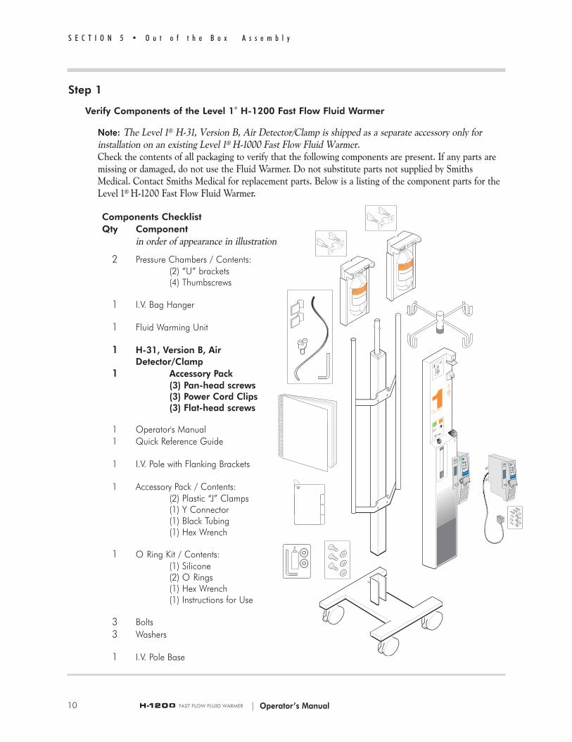
Note: The Level 1® H-31, Version B, Air Detector/Clamp is shipped as a separate accessory only forinstallation on an existing Level 1® H-1000 Fast Flow Fluid Warmer.Check the contents of all packaging to verify that the following components are present. If any parts aremissing or damaged, do not use the Fluid Warmer. Do not substitute parts not supplied by SmithsMedical. Contact Smiths Medical for replacement parts. Below is a listing of the component parts for theLevel 1® H-1200 Fast Flow Fluid Warmer.
Components ChecklistQty Component
in order of appearance in illustration
2 Pressure Chambers / Contents:(2) “U” brackets(4) Thumbscrews
1 I.V. Bag Hanger
1 Fluid Warming Unit
1 H-31, Version B, Air Detector/Clamp
1 Accessory Pack(3) Pan-head screws(3) Power Cord Clips(3) Flat-head screws
1 Operator's Manual1 Quick Reference Guide
1 I.V. Pole with Flanking Brackets
1 Accessory Pack / Contents:(2) Plastic “J” Clamps(1) Y Connector(1) Black Tubing(1) Hex Wrench
1 O Ring Kit / Contents:(1) Silicone(2) O Rings(1) Hex Wrench(1) Instructions for Use
3 Bolts3 Washers
1 I.V. Pole Base
S E C T I O N 5 • O u t o f t h e B o x A s s e m b l y
| Operator’s Manual10

| Operator’s Manual
Step 2
Assemble I.V. Pole to the Warming Unit
There are three steps involved in assembling the I.V. Pole to the Warming Unit. The steps are: 1. Assemble the I.V. Pole to the Base, 2. Close the Drain Valve, and 3. Attach the Warming Unit to theFlanking Brackets. Each step is detailed in a short procedure.
2.1 Assemble the I.V. Pole to the Base
1 Locate the I.V. Pole Base (a).
2 Locate the dark-gray extruded I.V. Pole (b) with FlankingBrackets.
3 Place the I.V. Pole Base upright on its wheels, (c) and lock the wheels to prevent movement during set up.
4 Locate three bolts (d) and washers for the pole base.
5 Align the three holes (e) in the I.V. Pole with the three screw holes on the pole base.
6 Slide the I.V. Pole down over the pole base, (f) keeping holes aligned.
7 Guide three bolts and washers through the holes (g) at the base of the pole and tighten.
2.2 Close the Drain Valve
Turn valve, located on the bottom of the device, perpendicular to stem (h) of the Warming Unit as shown.
S E C T I O N 5 • O u t o f t h e B o x A s s e m b l y
11
a
b
c
d
e
f
g
h

2.3 Attach the Warming Unit to the Flanking Brackets
1 Align the eight hex screws on the back of the Warming Unit with the eight keyhole notches on the flanking bracket.
2 Slide screw heads down into keyhole notches.
3 Tighten all eight hex screws with the supplied hexwrench and secure in place.
2.4 Attach the Quick Reference Guide to theFluid Warmer by sliding the ring on theQuick Reference Guide over one of thepoles on the Flanking Bracket.
Step 3
Install the Pressure Chambers
1 Locate the two Pressure Chambers.
2 Locate the U-brackets and thumbscrews supplied with thePressure Chambers.
3 Attach the U-brackets with thumbscrews to the back of the PressureChambers, as shown. Keep thumbscrews and brackets loose.
4 Slide one Pressure Chamber with attached U-bracket over the top of each flanking pole.
5 Align the U-bracket slightly below the top of the flanking pole. Tighten the thumbscrews securely.
12
S E C T I O N 5 • O u t o f t h e B o x A s s e m b l y
| Operator’s Manual

AX
1
2
LEVEL
SYSTEM 1
000
a
b
c
| Operator’s Manual
Step 4
Attach the I.V. Bag Hanger
1 Slide the I.V. Bag Hanger on top of the I.V. Pole.
2 Align with tabs.
3 Press down and snap into place.
Step 5
Disinfect the Recirculating Solution Reservoir
1 Remove the fill-port plug (a) on the reservoir.
2 Prepare a 0.3% hydrogen peroxide/distilled water solution for the reservoir. Mix 140 ml of 3% hydrogen peroxide solution and1,260 ml of distilled water.
3 Fill the reservoir with 1.4 liters of 0.3% hydrogen peroxide/distilled water solution.
4 Replace the fill-port plug.
5 Insert a Disposable Set into the Fluid Warmer.
6 Insert the power cord into a properly grounded receptacle.
7 Turn the Fluid Warmer ON. Let the solution circulate for a 30-minute disinfection period.
8 Turn the Fluid Warmer OFF.
9 Empty the reservoir.
10 Remove the Disposable Set and discard according to established hospital procedures.
S E C T I O N 5 • O u t o f t h e B o x A s s e m b l y
13

AX
1
2
LEVEL
SYSTEM 1
000
a
b
c
b
a
c
14
S E C T I O N 5 • O u t o f t h e B o x A s s e m b l y
| Operator’s Manual
Step 6
Preliminary Preparation
1 Remove the fill-port plug (a) on the front of the warming unit andfill the reservoir to the maximum level with 1.4 liters of one of thefollowing solutions:
• 0.3% Hydrogen Peroxide/Distilled Water SolutionMix 140 ml of 3% hydrogen peroxide and 1,260 ml of distilledwater.Note: If this option is selected, the maintenance requirement to change the recirculating solution is once every 12 months. Always use a 0.3% hydrogen peroxide/distilled water solution when refilling the reservoir.
• Distilled WaterNote: If this option is selected, the maintenance requirement to change the recirculating solution is once every 30 days.
2 Replace the fill port plug.
3 Lubricate O-Rings in #1 Block (b) and #2 Block (c). Place a smallamount of silicone lubricant, provided in the supplied O-Ring Kit,on a cotton swab and apply all around the inside of each O-Ring.
Step 7
Connect the Pneumatic Tubing
1 Locate the Accessory Pack with the black pneumatic tubing (a), two “J” clamps (b), and one “Y” Connector (c).
2 Locate the orange protective plug in the red ring connector (d) located on the back of the device. Remove the plug by depressing the red plastic ring as you pull the plug out of the connector.
3 Take the pneumatic tubing and press one end of the tubing firmly into the ring connector (d) until it can go no further.
4 Take the “Y” connector and press the other end of the pneumatic tubing into the bottom of the “Y” connector, as shown (e), until it can go no further.

d
e
f
g
h
F1
Two Fuse Configuration Four Fuse Configuration
F1
| Operator’s Manual
5 Press the pneumatic tubing from the Pressure Chamberinto place (f) on the top of the “Y” connector until it cango no further. Repeat this procedure with the pneumatictubing from the other Pressure Chamber.
6 Remove the protective backing sheet on one “J” clamp,exposing the adhesive side.
7 Carefully position the “J” clamp and press the adhesive side against the gray I.V. Pole in the approximate locations (g)(h) shown.
Press down firmly to secure in place.
Repeat this procedure for the other “J” clamp.
8 Press the pneumatic tubing into place on the “J” clamps.
Step 8
Install the Level 1® H-31, Version B, Air Detector/Clamp
Before installing the Air detector, determine if the the Fluid Warmer was manufactured before 2004. If it is, inspect the "F1" fuse to confirm that it is the correct value and type. The year of manufacture can be determined by the serial number label which is located on the bottom right side of the unit, or for older units on the inside.If the first four characters of the serial numberare numbers, then the numbers represent the year of manufacture (e.g. 20040100 would be manufactured in 2004). If the first character of the serial number is the letter "J", then the year of manufacture is prior to 2004 (the letter “S” indicates the year 2007 or later). For units manufactured prior to 2004, perform the following.
1 Disconnect the power.
2 Remove the 18 screws from the rear of the FluidWarmer and remove the back panel.
3 Locate the “F1” fuse on the electronic assembly.See figures to locate the “F1” fuse for either a twofuse configuration or a four fuse configuration.
S E C T I O N 5 • O u t o f t h e B o x A s s e m b l y
15

| Operator’s Manual
b
• For 100 - 120V Fluid Warmers,Remove the fuse and verify that T6.3AL250V (time lag, 6.3 amp, 250V fuse), is printed on one of the silver end caps, if not replace the fuse with a new fuse marked T6.3AL250V.
• For 220 - 240V Fluid Warmers,Remove the fuse and verify that T3.15AL250V (time lag, 3.15 amp, 250V fuse), is printed on one of the silver end caps, if not replace the fuse with a new fuse marked T3.15AL250V.
4 Replace the back panel and insert all but 6 of the screws (a) as indicated in Step 1 below. Then proceed to install the Air Detector/Clamp.
To install the Air Detector/Clamp,
1 Remove 6 screws (a) from the rear of the Fluid Warmer, lower left side, from locations shown in figure.
2 Plug in the power cord (b) of the Level 1® H-31, Version B,Air Detector/Clamp into the auxiliary MAINS outlet located on the bottom of the Fluid Warmer.
Note: If you turn the Fluid Warmer off and the AirDetector/Clamp does not turn off, contact Smiths Medicalor your local Smiths Medical distributor.
3 Loosen the three screws holding the mounting bracket to therear of the Air Detector/Clamp (do not remove).
4 Align the slot on the Air Detector/Clamp with #3 Block onthe Fluid Warmer (c). Fit in place over the block.
Note: Do not bend the mounting bracket while holding theAir Detector/Clamp against the fluid Warmer.
5 Carefully align the mounting bracket on the rear of the AirDetector/Clamp with three screw holes, shown (d). Ensurethat the gasket seal on the Air Detector/Clamp is flush withthe Fluid Warmer. Insert three flat-head screws and tighten,securing the Air Detector/Clamp to the Fluid Warmer.Tighten the three screws on the mounting bracket on theAir Detector/Clamp.
6 Locate three power cord clips (e) included with the AirDetector/Clamp and snap onto power cord. Align clips withthe three screw holes as shown, insert screws, and tighten.
S E C T I O N 5 • O u t o f t h e B o x A s s e m b l y
16
d
a
e
a
a
a
c
a
a
e
e

| Operator’s Manual
7 Install and prime a Level 1® Fast Flow I.V. Disposable Administration Set, and test the audible and visual alarms and Air Detection/Clamp as described in Section 9 Operating Instructions.
Step 9
Perform Electrical Safety Tests
Perform all applicable electrical safety tests as required per institutional procedure. These include but are not limited to:
• Leakage current • Hypot • Ground bond test
WARNING!
Grounding reliability can only be achieved when MAINS powercords are connected to a properly grounded receptacle. Risk ofelectrical shock exists if the equipment is not connected to aproperly grounded receptacle resulting in death or serious injury to the patient or user.
The Electrical Safety Check must be performed by competent personnel authorized by the institution to perform such testing. The Safety Checkmust be performed and documented at least once per year, or accordingto institutional policy.
S E C T I O N 5 • O u t o f t h e B o x A s s e m b l y
17
S E C T I O N 6 • P r i n c i p l e o f O p e r a t i o n
| Operator’s Manual
H-1200H-1200
18

| Operator’s Manual
S E C T I O N 6
Principle of Operation
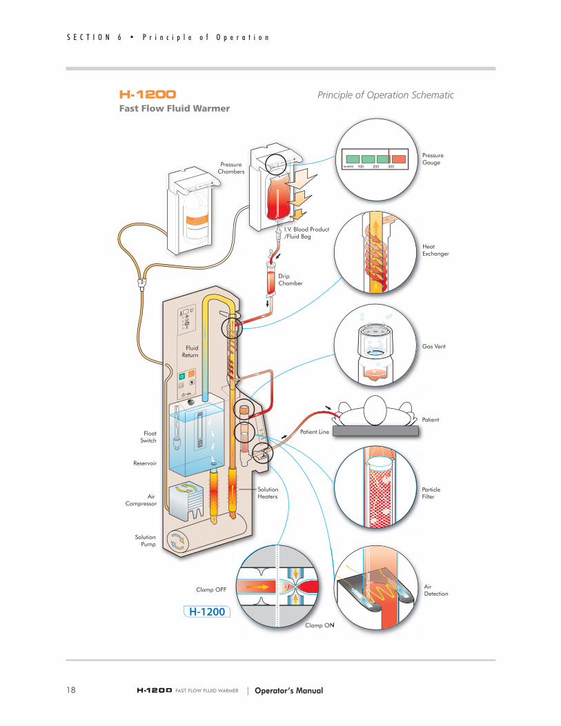
The schematic illustration on the facing page depicts the Level 1® H-1200 FastFlow Fluid Warmer’s (Fluid Warmer) operations. The primary operations aredescribed below.
Fluid Warming
The Fluid Warmer utilizes a solution reservoir housed in a controllerunit. Recirculating solution is warmed and pumped through a heatexchanger (a part of the Disposable Set). The solution is returned tothe reservoir for continuous recirculation and remains isolated from thepatient and from the I.V. fluid path. The on-board recirculating solutionis heated to a pre-set manufacturer’s temperature set-point. The systemcontinuously monitors and controls the recirculating solutiontemperature. The Fluid Warmer is designed to shut down and provideaudible and visual alarms in the event of an over-temperature condition.
Pressurized Fluid Delivery
The Fluid Warmer provides pressurized fluid delivery through the use ofan on-board compressor and two Pressure Chambers. The PressureChambers pressurize the fluid bags for fast fluid delivery.
Air Detection/Clamping
The Air Detector/Clamp detects the presence of air in the GasVent/Filter Assembly—a part of the Level 1® D/DI series DisposableAdministration Sets (Disposable Sets)—and clamps the patient line. Anultrasonic signal continually passes through the fluid-filled GasVent/Filter Assembly. As a bolus of air displaces the fluid in the GasVent/Filter Assembly, the ultrasonic signal is broken and the clampcloses, stopping the air before it enters the patient line. Audible andvisual alarms are activated, notifying the user that air has been detectedand fluid flow has been clamped off. Clearing the bolus of air andrestoring the fluid flow are quickly accomplished without disconnectingfrom the patient.
S E C T I O N 6 • P r i n c i p l e o f O p e r a t i o n
19

F-50F-50Gas Vent/Filter Assembly
| Operator’s Manual
F-50 Gas Vent/Filter Assembly
The D/DI-65HL, D/DI-75, D/DI-150, and D/DI-350 DisposableAdministration Sets contain the F-50 Gas Vent/Filter Assembly.
The F-50 GasVent/Filter Assembly utilizes a float assembly contained ina fluid chamber to prevent air from entering the patient line. As theDisposable Set primes, fluid fills the fluid chamber raising the floatassembly to allow fluid to flow to the patient. Any air in the line duringpriming is vented through a hydrophobic filter membrane. Duringnormal operation, fluid passes through a particle filter, into the fluidchamber and to the patient line. When air enters the F-50 GasVent/Filter Assembly, the volume of fluid in the fluid chamber decreasescausing the float assembly to drop down and close the fluid path, whichstops flow to the patient. Air in the fluid chamber is vented through thehydrophobic membrane (gas vent) located under the vent cap. After airhas vented out and fluid re-enters the fluid chamber, the float assemblyrises to open the fluid path and resume flow to the patient.
S E C T I O N X • T i t l e
20

21| Operator’s Manual
S E C T I O N 7
Controls and Displays
Five locations on the Level 1® H-1200 Fast Flow Fluid Warmer (FluidWarmer) govern how the device is controlled and where functionindicators are displayed. They are called-out in the figure and aredefined in the list below.
1 Fluid Warmer Display Panel
2 Power and Alarm Test Panel
3 Reservoir Level Display
4 Air Detector/Clamp Control Panel
5 Pressure Chamber Control Panel
The Fluid Warmer has five Interlocks, which detect for correctinstallation of a Disposable Set, that are also defined this section.

| Operator’s Manual
Fluid Warmer Power and Alarm Test Panel
The Power and Alarm Test Panel is located on the front of the FluidWarmer directly above the reservoir fill-cap. This panel contains fourpressure-sensitive buttons that are activated when pressed. Refer to thePower Alarm Test Panel (figure on right) whose numbered call outs correspond to a description of the button and the function it performs.
Button/Function
1 Power ON ButtonThe green button on the top-left of the Power and Alarm TestPanel powers on the device. Power is applied to the on-boardcompressor for the pressure chambers and the AirDetector/Clamp. The green Automatic Operation LED on theFluid Warmer Display Panel illuminates when the Power ONbutton is activated, with a Disposable Set in place.
2 Power OFF ButtonThe Power OFF is the orange button to the right of the PowerON button on the Power and Alarm Test Panel. This buttonturns power off to the unit. The green Automatic OperationLED on the Display Panel will turn off when this button ispressed.
3 Over Temperature Test ButtonThe Over Temperature Test is used to confirm the properoperation of the Over Temperature circuitry. Testing the circuitryrequires that the Fluid Warmer is at operating temperature(41°C). Once this is established, press and hold the button. Then, release the button. The Over Temperature alarmcontinues to function. Clear the alarm mode by turning thedevice off, then back on. See Section 11, Testing, for instructionon performing an Over Temperature Test.
4 Fluid Warmer Alarm Signal Test ButtonThe Fluid Warmer Alarm Signal Test is used to confirm properoperation of the visual and audible alarm indicators. Press andhold this button to test circuitry. Then, release the button. TheOver Temperature alarm continues to function. Clear the alarmmode by turning the device off, then back on.
5 Reservoir CapacityCapacity for recirculating solution reservoir is 1.4 liters. Use recirculating solution. Do not exceed maximum capacity.
S E C T I O N 7 • C o n t r o l s a n d D i s p l a y s
22

| Operator’s Manual
Fluid Warmer Display Panel
The Fluid Warmer Display Panel provides continuous informationabout the operation of the Fluid Warmer. A liquid crystal display (LCD) indicates recirculating solution temperature. Just below the LCD, fourlight-emitting diodes (LEDs) indicate operation modes for the device.For identification purposes, the diodes are shown illuminated.
1 Recirculating Solution TemperatureThe temperature of the recirculating solution is displayed in theLCD panel. The temperature is displayed in degrees celsius.
Note: This is NOT the temperature of fluid delivered to thepatient—the display reflects the temperature of the recirculatingsolution.
2 Automatic Operation LEDThe green LED indicator illuminates when the power is ON andthe Disposable Set has been properly installed. When lit, thisindicates the Fluid Warmer is operating.
3 Check Disposables LEDThe yellow LED indicator illuminates and an audible attentionsignal beeps when the Disposable Set is not properly installed.See the Interlocks description in this section for directions onclearing the Check Disposables alarm.
4 Add Recirculating Solution LEDThe yellow LED indicator illuminates and an audible attentionsignal beeps when reservoir is low. Additional recirculatingsolution must be added to the reservoir. Maximum capacity forthe reservoir is 1.4 liters of recirculating solution.
5 Over Temperature LEDThe red LED indicator illuminates and an audible warning signalbeeps when the recirculating solution is over the acceptable temperature for safe use.
Reservoir Level Display
The Reservoir Level Display has a clear window for viewing the amountof recirculating solution present in the reservoir. Check the reservoir toensure the solution level is near the maximum level indicator (a). If therecirculating solution level is too low, the Add Recirculating SolutionLED on the Display Panel illuminates and an audible attention signalbeeps.
S E C T I O N 7 • C o n t r o l s a n d D i s p l a y s
23
a
| Operator’s Manual
Air Detector/Clamp Control Panel and Alarms
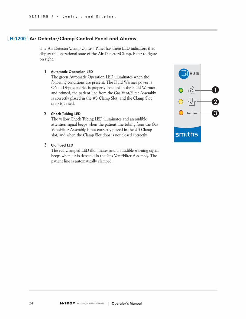
The Air Detector/Clamp Control Panel has three LED indicators thatdisplay the operational state of the Air Detector/Clamp. Refer to figureon right.
1 Automatic Operation LEDThe green Automatic Operation LED illuminates when the following conditions are present: The Fluid Warmer power isON, a Disposable Set is properly installed in the Fluid Warmerand primed, the patient line from the Gas Vent/Filter Assemblyis correctly placed in the #3 Clamp Slot, and the Clamp Slotdoor is closed.
2 Check Tubing LEDThe yellow Check Tubing LED illuminates and an audible attention signal beeps when the patient line tubing from the GasVent/Filter Assembly is not correctly placed in the #3 Clampslot, and when the Clamp Slot door is not closed correctly.
3 Clamped LEDThe red Clamped LED illuminates and an audible warning signalbeeps when air is detected in the Gas Vent/Filter Assembly. Thepatient line is automatically clamped.
S E C T I O N 7 • C o n t r o l s a n d D i s p l a y s
24
| Operator’s Manual
Pressure Chamber Control Panel
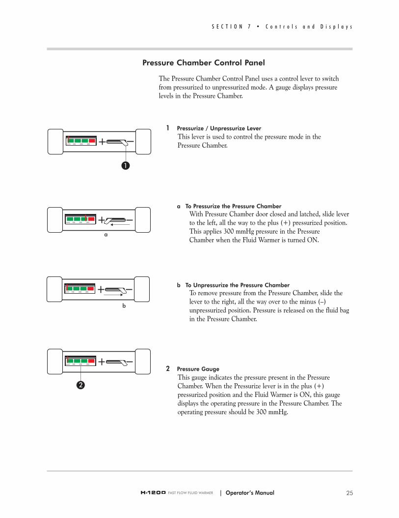
The Pressure Chamber Control Panel uses a control lever to switchfrom pressurized to unpressurized mode. A gauge displays pressure levels in the Pressure Chamber.
1 Pressurize / Unpressurize LeverThis lever is used to control the pressure mode in the Pressure Chamber.
a To Pressurize the Pressure ChamberWith Pressure Chamber door closed and latched, slide lever to the left, all the way to the plus (+) pressurized position. This applies 300 mmHg pressure in the Pressure Chamber when the Fluid Warmer is turned ON.
b To Unpressurize the Pressure ChamberTo remove pressure from the Pressure Chamber, slide the lever to the right, all the way over to the minus (–) unpressurized position. Pressure is released on the fluid bag in the Pressure Chamber.
2 Pressure GaugeThis gauge indicates the pressure present in the PressureChamber. When the Pressurize lever is in the plus (+)pressurized position and the Fluid Warmer is ON, this gaugedisplays the operating pressure in the Pressure Chamber. Theoperating pressure should be 300 mmHg.
S E C T I O N 7 • C o n t r o l s a n d D i s p l a y s
25
a
b

| Operator’s Manual
Interlocks
The Fluid Warmer has five Interlocks that detect for proper installationof a Disposable Set’s components. Refer to the figure on the facing pageto identify the positions of interlocks.
Note: Block 1 is not an Interlock. It cannot detect if a Disposable Setis not correctly installed. It is identified here because it is an essentialstep for proper installation of the Disposable Set components.
Three Interlocks are located on the Fluid Warmer and check for properinstallation of:
2 Heat Exchanger, top end4 Gas Vent/Filter Assembly5 Heat Exchanger (guide)
Two Interlocks are located in the Air Detector/Clamp 3 and check forthe proper installation of:
Patient I.V. Line in the Clamp SlotDoor for the Clamp Slot
Interlocks 2, 4, and 5 prevent the Fluid Warmer’s pump fromcirculating reservoir solution if the Disposable Set’s Heat Exchanger andGas Vent/Filter Assembly are not installed properly.
If Check Disposable Alarm is Activated on the Fluid Warmer
a Check Heat Exchanger for proper installation in Block 1, and Interlocks 2 and 5.
b Press Heat Exchanger down firmly in Block 1 to secure in O-Ring.
c Press Interlock 2 tab down firmly to engage the Interlock switch.
d Press Heat Exchanger firmly into Interlock 5.
e Check Gas Vent/Filter Assembly installation in Interlock 4.
If Check Tubing Alarm is Activated on the Air Detector/Clamp
a Open the door and check the Patient Line for proper installation inthe Clamp Slot at interlock 3.
b Close the door and check that the tab on the top edge of the door isfully inserted into the Air Detector/Clamp at interlock 3 before pushing the door down to close it.
S E C T I O N 7 • C o n t r o l s a n d D i s p l a y s
26

| Operator’s Manual
S E C T I O N 7 • C o n t r o l s a n d D i s p l a y s
27

| Operator’s Manual28
S E C T I O N 8 • O p e r a t i o n

29
S E C T I O N 8 • O p e r a t i o n
S E C T I O N 8
Operation
The Level 1® H-1200 Fast Flow Fluid Warmer (Fluid Warmer) performs threeprimary functions; Fluid Warming, Air Detection/Clamping, and PressurizedFluid Delivery. Functions are monitored and controlled by fourinterfaces/control panels located on the Fluid Warmer. The four interfaces are:
• Fluid Warmer Power and Alarm Test Panel• Fluid Warmer Display Panel• Air Detector/Clamp Alarm and Control Panel• Pressure Chamber Control Panel
In the table on the facing page, operation of the device is represented in termsof the four interfaces that control specific device functions. The numbers call-out individual Modes of Operation activated or indicated on the interface.
Functions• Fluid Warming • Air Detection/Clamping• Pressurized Fluid Delivery
Operational modes• OFF Mode• ON/Automatic Operation for Fluid Warmer• Alarm Test Mode• Over Temperature Test Mode• Check Disposables Mode• Add Recirculating Solution Mode• Over Temperature Alarm Mode• Power ON Test for Air Detector/Clamp• Automatic Operation Air Detector/Clamp• Check Tubing Mode• Air Detected/Clamped Mode• Pressurized Mode• Unpressurized Mode
The modes of operation are individually defined in the following section. Thisincludes a description of each mode, activation and/or monitoring of themode, mode characteristics, and clearing of the mode state.
| Operator’s Manual

| Operator’s Manual
Modes of Operation
WARNING!
If any visual indicator does not illuminate or the audible signaldoes not sound, do not use the Fluid Warmer. Remove thedevice from service immediately. Death or serious injury mayoccur to the patient or user if this warning is not followed.
OFF Mode
Power is off only for a part of the equipment. The MAINS are still connected. Press the OFF button (a) on the Power and Control Panel toturn the device off.
ON/Automatic Operation Mode for Fluid Warmer
The Fluid Warmer enters Automatic Operating mode when aDisposable Set is properly installed and the device is turned ON. This isdone by pressing the ON button (b).
Mode characteristics• The green Automatic Operating LED on the Display Panel
illuminates (c).• Fluid warming begins.• Pressure infusion is provided by activating the Pressure Chambers.• Air Detector/Clamp enters the Power ON Test, then enters default
Automatic Operation mode.
S E C T I O N 8 • O p e r a t i o n
30
a
b
c

Alarm Test Mode
The Alarm Test mode is used to test the visual and audible indicators ofthe Level 1® H-1200 Fast Flow Fluid Warmer. This mode is entered bypressing and holding the Alarm Test button (d) on the Fluid Warmer’sControl Panel.
Mode characteristics• All visual indicators on the Fluid Warmer’s Display Panel (e)
illuminate.• The Fluid Warmer’s audible alarm beeps.• When the Alarm Test button is released, the Over Temperature
LED and an audible alarm remains active.• To clear the Over Temperature alarm, turn the Fluid Warmer OFF
and then back ON.
Over Temperature Test Mode
The Over Temperature Test mode is used to test the operation of theFluid Warmer’s Over Temperature Circuitry. This mode is entered bypressing and holding the Over Temperature Test button (f) on the FluidWarmer Control Panel with the Fluid Warmer at operating temperature(41°C).
Mode characteristics• The red Over Temperature LED (g) on the Display Panel
illuminates.• An audible warning signal beeps.
To Clear this mode • Turn Fluid Warmer OFF.• Turn Fluid Warmer back ON.
Temperature Display
The Temperature Display functions when the Fluid Warmer is poweredON. Temperature is displayed in degrees Celsius.
S E C T I O N 8 • O p e r a t i o n
31| Operator’s Manual
f
g
d
e

| Operator’s Manual
Check Disposables Mode
The Check Disposables mode of the Fluid Warmer indicates a missingor improperly installed Disposable Set.
Mode characteristics• The Check Disposables yellow LED (a) on the Fluid Warmer’s
Display Panel is illuminated. • An audible attention signal beeps.• Reservoir solution circulation is stopped; fluid warming stops.• Pressure Chambers continue to operate.
To Clear this mode Install a disposable or check the disposable installation as follows:• Check the position of the disposable in the #1 Block.• Make sure the heat exchanger is seated in the heat exchanger guide.• Press down firmly on the #2 Block.• Check the position of the Gas Vent/Filter Assembly in the #4
Interlock.
Add Recirculating Solution Mode
The Add Recirculating Solution mode of the Fluid Warmer indicatesthat the solution level in the recirculating solution reservoir is below itsminimum level.
Mode characteristics• The yellow Add Recirculating Solution LED (b), on the Fluid
Warmer’s Display Panel, is illuminated • An audible warning signal beeps.• Solution circulation stops, fluid warming stops.• Pressure Chambers continue to operate.• Fluid flow to the patient continues.
To Clear this mode Add recirculating solution to the Fluid Warmer’s reservoir.
S E C T I O N 8 • O p e r a t i o n
32
a
b
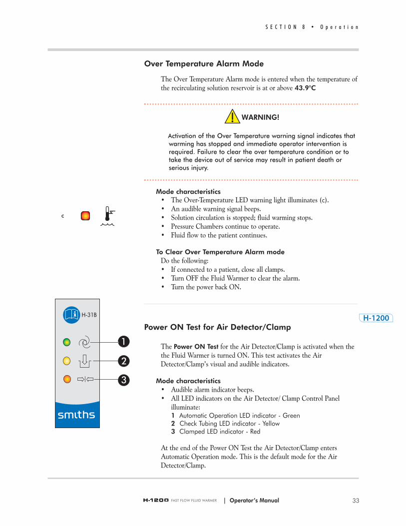
Over Temperature Alarm Mode
The Over Temperature Alarm mode is entered when the temperature ofthe recirculating solution reservoir is at or above 43.9°C
WARNING!
Activation of the Over Temperature warning signal indicates that warming has stopped and immediate operator intervention isrequired. Failure to clear the over temperature condition or totake the device out of service may result in patient death orserious injury.
Mode characteristics• The Over-Temperature LED warning light illuminates (c).• An audible warning signal beeps.• Solution circulation is stopped; fluid warming stops.• Pressure Chambers continue to operate.• Fluid flow to the patient continues.
To Clear Over Temperature Alarm mode Do the following:• If connected to a patient, close all clamps.• Turn OFF the Fluid Warmer to clear the alarm.• Turn the power back ON.
Power ON Test for Air Detector/Clamp
The Power ON Test for the Air Detector/Clamp is activated when thethe Fluid Warmer is turned ON. This test activates the AirDetector/Clamp’s visual and audible indicators.
Mode characteristics• Audible alarm indicator beeps.• All LED indicators on the Air Detector/ Clamp Control Panel
illuminate:1 Automatic Operation LED indicator - Green2 Check Tubing LED indicator - Yellow3 Clamped LED indicator - Red
At the end of the Power ON Test the Air Detector/Clamp entersAutomatic Operation mode. This is the default mode for the AirDetector/Clamp.
S E C T I O N 8 • O p e r a t i o n
33| Operator’s Manual
c

| Operator’s Manual
Automatic Operation Air Detector/Clamp
In Automatic Operating mode, the Air Detector/Clamp monitors forthe presence of air in the Disposable Set’s Gas Vent/Filter Assembly. Ifair is detected the patient line is clamped off and an audible alarmbeeps. The Air Detector/Clamp goes into Automatic Operation modewhen the Fluid Warmer is turned ON and Disposable Set is properlyinstalled and primed—no air is present in the Gas Vent/Filter Assembly.
Mode characteristics• The green Automatic Operation LED (1) is illuminated. • Monitoring for air in the Gas Vent/Filter Assembly is active.• Fluid is ready to be delivered to the patient when in Automatic
Operating mode.
Check Tubing Mode
The Air Detector/Clamp’s Check Tubing mode is entered when thepatient line from the the Gas Vent/Filter Assembly is not properlyinstalled in the Air Detector/Clamp Slot and when the Clamp Slot dooris not closed correctly.
Mode characteristics• The yellow Check Tubing LED (b) on the Air Detector/Clamp
Control Panel is illuminated.• An audible low-priority warning signal beeps.
To Clear this mode • Place the patient line from the Gas Vent/Filter Assembly in the
#3 Clamp Slot of the Air Detector/Clamp and close the Clamp Slotdoor.
S E C T I O N 8 • O p e r a t i o n
34
b
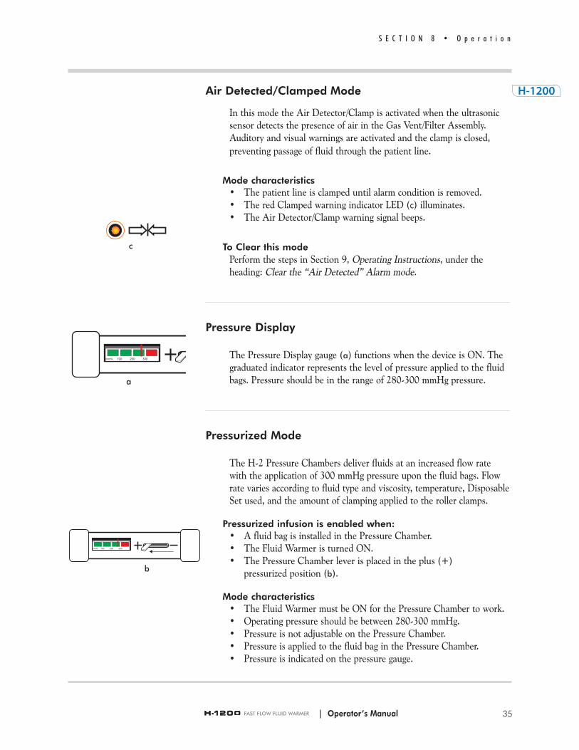
Air Detected/Clamped Mode
In this mode the Air Detector/Clamp is activated when the ultrasonicsensor detects the presence of air in the Gas Vent/Filter Assembly.Auditory and visual warnings are activated and the clamp is closed, preventing passage of fluid through the patient line.
Mode characteristics• The patient line is clamped until alarm condition is removed.• The red Clamped warning indicator LED (c) illuminates.• The Air Detector/Clamp warning signal beeps.
To Clear this mode Perform the steps in Section 9, Operating Instructions, under the heading: Clear the “Air Detected” Alarm mode.
Pressure Display
The Pressure Display gauge (a) functions when the device is ON. The graduated indicator represents the level of pressure applied to the fluidbags. Pressure should be in the range of 280-300 mmHg pressure.
Pressurized Mode
The H-2 Pressure Chambers deliver fluids at an increased flow ratewith the application of 300 mmHg pressure upon the fluid bags. Flowrate varies according to fluid type and viscosity, temperature, DisposableSet used, and the amount of clamping applied to the roller clamps.
Pressurized infusion is enabled when:• A fluid bag is installed in the Pressure Chamber.• The Fluid Warmer is turned ON.• The Pressure Chamber lever is placed in the plus (+)
pressurized position (b).
Mode characteristics• The Fluid Warmer must be ON for the Pressure Chamber to work.• Operating pressure should be between 280-300 mmHg.• Pressure is not adjustable on the Pressure Chamber.• Pressure is applied to the fluid bag in the Pressure Chamber.• Pressure is indicated on the pressure gauge.
S E C T I O N 8 • O p e r a t i o n
35| Operator’s Manual
c
a
b
c
36
S E C T I O N 8 • O p e r a t i o n
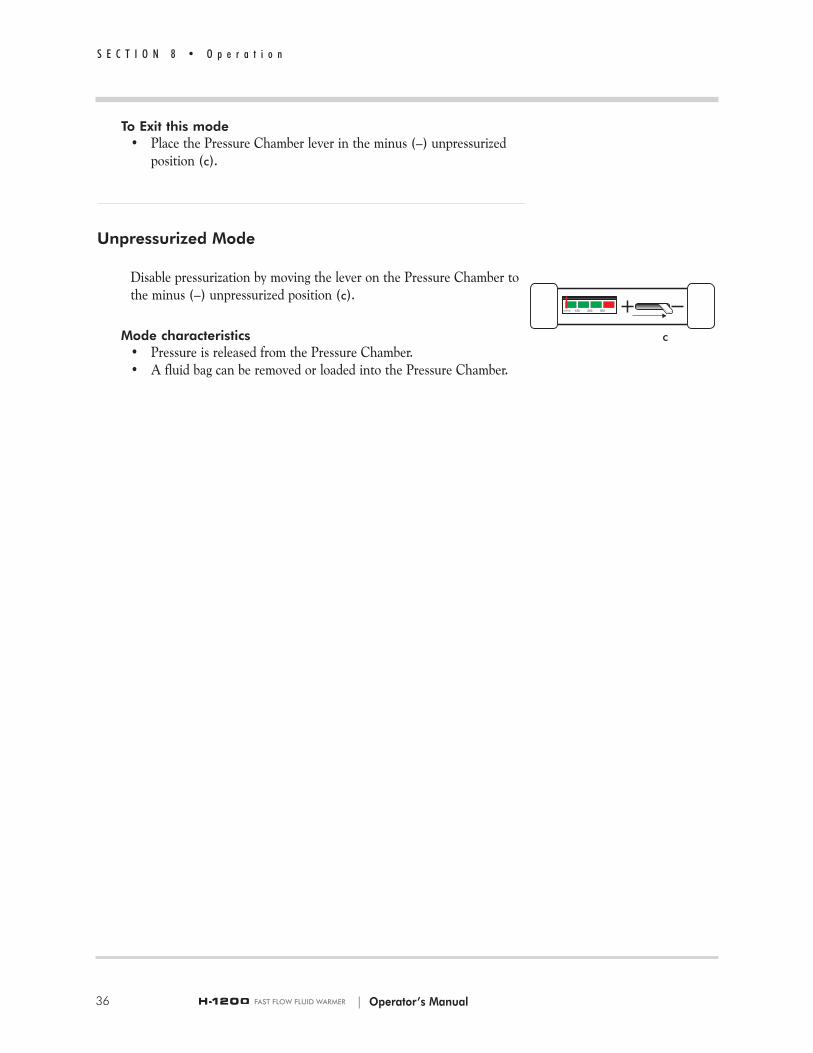
To Exit this mode • Place the Pressure Chamber lever in the minus (–) unpressurized
position (c).
Unpressurized Mode
Disable pressurization by moving the lever on the Pressure Chamber tothe minus (–) unpressurized position (c).
Mode characteristics• Pressure is released from the Pressure Chamber.• A fluid bag can be removed or loaded into the Pressure Chamber.
| Operator’s Manual
37
S E C T I O N 9 • O p e r a t i n g I n s t r u c t i o n s
S E C T I O N 9
Operating InstructionsThe Operating Instructions are grouped into five segments. Read througheach section BEFORE performing a procedure.
WARNINGS
• The Fluid Warmer is for use only with Smiths Medical supplied or approved parts, accessories, and D or DI series Disposable Sets. The device may not function as intended with the use of unapproved parts, accessories, or Disposable Sets resulting in death or serious injury to the patient or user.
• When injecting medications into the fluid path, do not inject through the triple-lumen tubing of the Level 1® D/DI-60HL and D/DI-65HL Disposable Set. This may allow communicationbetween the recirculating solution path and I.V. fluid path, whichcould result in death or serious injury to the patient.
• Replace Gas Vent/Filter Assembly every three hours, or when the filter becomes clogged, or when air is slowly vented.Failure to do so will result in a reduction of flow rate. This may result in inadequate patient treatment resulting in death or serious injury to the patient.
• The replacement Gas Vent/Filter Assembly must be fully primed before continuing infusion. Failure to do so may allow air to be infused into the patient resulting in death or serious injury to the patient.
• Grounding reliability can only be achieved when MAINS power cords are connected to a properly grounded receptacle. Risk of electrical shock exists if the equipment is not connected to a properly grounded receptacle resulting in death or serious injury to the patient or user.
• Do not bend the heat exchanger. Bending may damage the heat exchanger allowing communication between the recirculating solution path and I.V. fluid path, resulting in the I.V. delivery of inappropriate fluids which could result in death or serious injury to the patient.
• The tubing must be properly placed in the Clamp Slot of the Air Detector/Clamp. Failure to ensure that the tubing is correctly positioned in the Clamp Slot may result in failure to stop air infusion which may result in patient death or serious injury.
| Operator’s Manual
| Operator’s Manual
9.1 Set Up for Use
WARNINGS
• Read and follow all instructions, labeling, and accompanying documents supplied with this medical device. Failure to follow instructions, including all warnings and cautions, could result in death or serious injury to the patient or user.
• Disposable Sets are supplied with a sterile fluid path which may be compromised if the caps are not in place. Do not use Disposable Set if Luer and spike caps are not securely in place, or if Luer connections are not secure as the fluid path may not be sterile and may cause death or serious injury to the patient.
• Disposable Sets are for single use only. To reduce the risk of cross contamination, do not reuse Disposable Sets, which could result in death or serious injury to the patient.
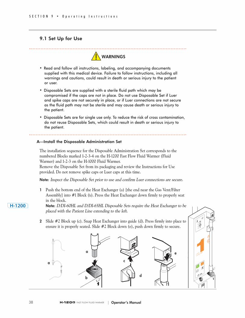
A—Install the Disposable Administration Set
The installation sequence for the Disposable Administration Set corresponds to thenumbered Blocks marked 1-2-3-4 on the H-1200 Fast Flow Fluid Warmer (FluidWarmer) and 1-2-3 on the H-1000 Fluid Warmer.Remove the Disposable Set from its packaging and review the Instructions for Useprovided. Do not remove spike caps or Luer caps at this time.
Note: Inspect the Disposable Set prior to use and confirm Luer connections are secure.
1 Push the bottom end of the Heat Exchanger (a) [the end near the Gas Vent/Filter Assembly] into #1 Block (b). Press the Heat Exchanger down firmly to properly seat in the block. Note: D/DI-60HL and D/DI-65HL Disposable Sets require the Heat Exchanger to be placed with the Patient Line extending to the left.
2 Slide #2 Block up (c). Snap Heat Exchanger into guide (d). Press firmly into place toensure it is properly seated. Slide #2 Block down (e), push down firmly to secure.
a
S E C T I O N 9 • O p e r a t i n g I n s t r u c t i o n s
38
b
c
d
ea
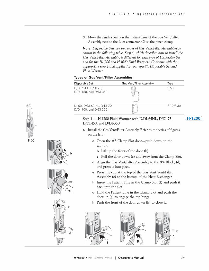
3 Move the pinch clamp on the Patient Line of the Gas Vent/Filter Assembly next to the Luer connector. Close the pinch clamp.
Note: Disposable Sets use two types of Gas Vent/Filter Assemblies asshown in the following table. Step 4, which describes how to install theGas Vent/Filter Assembly, is different for each type of Disposable Setand for the H-1200 and H-1000 Fluid Warmers. Continue with theappropriate step 4 that applies for your specific Disposable Set andFluid Warmer.
Types of Gas Vent/Filter Assemblies
Disposable Set Gas Vent/Filter Assembly Type
D/DI 65HL, D/DI 75, F 50D/DI 150, and D/DI 350
DI 50, D/DI 60 HL, D/DI 70, F 10/F 30D/DI 100, and D/DI 300
Step 4 — H-1200 Fluid Warmer with D/DI-65HL, D/DI-75, D/DI-150, and D/DI-350.
4 Install the Gas Vent/Filter Assembly. Refer to the series of figures on the left.
a Open the #3 Clamp Slot door—push down on the tab (a).b Lift up the front of the door (b).c Pull the door down (c) and away from the Clamp Slot.
d Align the Gas Vent/Filter Assembly to the #4 Block, (d) and press it into place.
e Press the clip at the top of the Gas Vent Vent/Filter Assembly (e) to the bottom of the Heat Exchanger.
f Insert the Patient Line in the Clamp Slot (f) and push it back into the slot.
g Hold the Patient Line in the Clamp Slot and push the door up (g) to engage the top hinge.
h Push the front of the door down (h) to close it.
| Operator’s Manual
S E C T I O N 9 • O p e r a t i n g I n s t r u c t i o n s
39
F-50
b
a
c
f
hg
d
e

40
S E C T I O N 9 • O p e r a t i n g I n s t r u c t i o n s
Step 4 — H-1200 Fluid Warmer with DI-50, D/DI-60HL, D/DI-70,D/DI-100, and D/DI-300.
4 Install the Gas Vent/Filter Assembly. Refer to the series of figures on the left.
a Open the #3 Clamp Slot door—push down on the tab (a). b Lift up the front of the door (b).c Pull the door down (c) and away from the Clamp Slot.
d Insert the Patient Line in the Clamp Slot (d) and push it back into the slot.
e Hold the Patient Line in the Clamp Slot and push the door up (e) to engage the top hinge. Then push the front of the door down to close it.
f Pull the Patient Line to the right (f) to align it in the Clamp Slot without kinking.
g Align the Gas Vent/Filter Assembly to the #4 Block, (g) and press it into place.
Step 4 — H-1000 Fluid Warmer with D/DI-65HL, D/DI-75, D/DI-150, and D/DI-350.
4 Install the Gas Vent/Filter Assembly.a Align the Gas Vent/Filter Assembly to the #3 Block,
and press it into place.b Press the clip at the top of the Gas Vent Vent/Filter
Assembly to the bottom of the Heat Exchanger.c Press the green Power ON button, located on the Power
and Alarm Test Panel, to turn ON the Fluid Warmer.
Step 4 — H-1000 Fluid Warmer with DI-50, D/DI-60HL, D/DI-70,D/DI-100, and D/DI-300.
4 Install the Gas Vent/Filter Assembly.a Align the Gas Vent/Filter Assembly to the #3 Block,
and press it into place.b Press the green Power ON button, located on the Power
and Alarm Test Panel, to turn ON the Fluid Warmer.
| Operator’s Manual
F-50
b
a
c
d e f g
F-10/30
F-10/30

a
| Operator’s Manual 41
S E C T I O N 9 • O p e r a t i n g I n s t r u c t i o n s
B—Prime the Disposable Administration Set
1 Close the Disposable Set clamps above the Heat Exchanger.• For DI-50, D/DI-60HL, D/DI-65HL, D/DI-70, and
D/DI-75 Disposable Sets,– close pinch clamps below the bag spikes, and– close roller clamp below the drip chamber (a).
• For D/DI-100, D/DI-150, D/DI-300, and D/DI-350 Disposable Sets
– close pinch clamps below the drip chambers.
2 Remove all air from the fluid bag:a Invert solution bag.b Use aseptic technique. Pierce membrane of bag port
with spike of Disposable Set. Then withdraw spike.c Squeeze bag to exhaust ALL air.d Place spike in bag port. Do not allow air to re-enter bag.e Repeat this step for each fluid line to be used.
3 Slide lever on H-2 Pressure Chamber to the minus (–) unpressurized position.
4 Hang spiked fluid bag/s in Pressure Chamber:
a Release hinged latch, open door and hang fluid bag inside on tab appropriate for bag size.
b Close the door and secure latch.c Injection and Spike ports on the fluid bag should extend
from opening at the bottom of the Pressure Chambers without being obstructed.
Note: When installing Level 1® D/DI-300 and D/DI-350 series Disposable Sets, hang the third fluid bag from the I.V. pole.
CAUTION
• When loading fluid bags into H-2 Pressure Chambers, choose a hanging hook that allows the bag port to hang freely in the indented slot at the bottom of the chamber door. If bag ports are positioned above this slot, diminished flow could occur resulting in physical injury to the patient, user, and/or an adverse effect on the device or its performance.
5 Open clamp above Drip Chamber on Level 1® DI-50, D/DI-60HL, D/DI-65HL, D/DI-70, and D/DI-75 Disposable Administration Sets for each I.V. fluid bag being used to prime the drip chamber.

| Operator’s Manual
6 Prime Drip Chamber by squeezing drip chamber until one-half to three-quarters full of fluid.
Note: • DI-50, D/DI-60HL, D/DI-65HL, D/DI-70, and D/DI-75 series use a single drip chamber.
• D/DI-100, D/DI-150, D/DI-300, and D/DI-350 series use a separate drip chamber for each spiked bag. The clamp is below the drip chamber.
7 Open remaining clamps above the Heat Exchanger. Fluid flows into the Gas Vent/Filter Assembly.
8 For DI-50, D/DI 60HL, D/DI-70, D/DI 100, and D/DI 300 vigorously tap the Gas Vent/Filter Assembly to dislodge air bubbles from filter screen.
9 Press the green Power ON button, located on the Power and AlarmTest Panel, to turn ON the Fluid Warmer.
• The Air Detector/Clamp runs a Power ON Test.• All Air Detector/Clamp indicator LEDs illuminate.• The audible warning beeps.
– If the above does not occur, remove the device from service.• Upon completion of the Power On Test the Air Detector/Clamp
enters Operation mode with the Automatic Operation LED illuminated.
• If the Disposable Set is incorrectly installed, the Fluid Warmer’s Check Disposables attention indicator illuminates and the audible attention signal beeps. Check the installation of the Disposable Set following the directions provided in Section 6Controls and Displays, on Interlocks.
C—Prime the Patient Line
1 Remove the male Luer cap from the distal end of the Patient Line.
Note: On Level 1® D/DI-60HL and D/DI-65HL Disposable Administration Sets verify that no recirculating solution comes out of the distal end of the Patient Line.
S E C T I O N 9 • O p e r a t i n g I n s t r u c t i o n s
42

| Operator’s Manual
WARNING!
If fluid exits in the Patient Line or the D/DI-60HL and D/DI-65HLDisposable Set, replace the Disposable Set.
2 Open the pinch clamp below the Gas Vent/Filter Assembly.
3 Allow fluid to flow until no air is observed in the Patient Line and the line is primed with fluid. Then, close the roller clamp on thePatient Line. Note: On D/DI-60HL and D/DI-65HL Disposable Sets close roller clamp below Drip Chamber.
D—Test the Audible and Visual Alarms
Test the visual and audible alarm signals by performing the following steps.
1 Press and hold the Alarm Test button on the Fluid Warmer’s Power and Alarm Test Panel. • All Fluid Warmer visual alarm LEDs illuminate
and the audible alarm signal beeps.
2 Release the Alarm Test button; the Over Temperature alarm continues.
3 Clear the Over Temperature alarm condition.• Turn the Fluid Warmer OFF, then ON. • The Air Detector/Clamp runs a Power On Test.• The Air Detector/Clamp goes into Automatic operation.
S E C T I O N 9 • O p e r a t i n g I n s t r u c t i o n s
43

44
S E C T I O N 9 • O p e r a t i n g I n s t r u c t i o n s
E—Test the Air Detector/Clamp
WARNING!
The functional test for the Air Detector/Clamp accessory must be performed before each use. If any visual indicator does notilluminate or the audible signal does not sound, do not use theFluid Warmer. Remove the device from service immediately. Fullyfunctional visual and audible alarm systems are essential for thesafe use of the Air Detector/Clamp.
1 Slide the lever on the Pressure Chambers to the plus (+) pressurized position to pressurize fluid delivery.
2 Move the Gas Vent/Filter Assembly away from the Air Detector sensor as shown.
3 The following occurs:• The Air Detector clamp closes.• The red Clamped indicator LED illuminates.• The audible warning signal beeps.• Fluid Warmer disposable alarm activates.If any of the above does not occur, remove the device from service.
4 Open roller clamp on the Patient Line to verify that fluid does not flow.After verifying that no fluid is flowing, close the roller clamp completly. If fluid flow is observed, remove the device from service.
5 Return to normal operation by placing the Gas Vent/Filter Assemblyback into the #4 Block as shown.
6 The Air Detector/Clamp resumes Automatic Operation mode.• The green Automatic Operation LED on the
Air Detector/Clamp Control Panel illuminates.
7 The Fluid Warmer is now ready for patient connection. Unclamp Patient Line to begin infusion. Note: On D/DI-60HL and D/DI-65HL Disposable Sets open roller clamp below drip chamber.
Conclusion
This concludes Section 9.1, Set Up for Use. Operators can proceed tothe next Section 9.2, Use of the Fluid Warmer.
| Operator’s Manual
45
S E C T I O N 9 • O p e r a t i n g I n s t r u c t i o n s
WARNINGS
• Remove all air from the fluid bags before spiking and the fluid lines before connecting to the patient. Failure to do so can result in infusion of air into the patient resulting in death or serious injury to the patient.
• Do not reuse partially full fluid bags. Fluid bags that have been partially drained, un-spiked, and then reinstalled may contain air, which if used can result in infusion of air into the patient resulting in death or serious injury to the patient. Use only new fluid bags from which the air has been removed.
• Replace Gas Vent/Filter Assembly every three hours, or when the filter becomes clogged, or when air is slowly vented. Failure to do so will result in a reduction of flow rate. This may result in inadequate patient treatment resulting in death or serious injury to the patient.
• The Replacement Gas Vent/Filter Assembly must be fully primed before continuing infusion. Failure to do so may allow air to be infused into the patient which could result in patient death or serious injury.
CAUTION
• When loading fluid bags into Pressure Chambers, choose a hanging hook that allows the bag port to hang freely in the indented slot at the bottom of the chamber door. If bag ports are positioned above this slot, diminished flow could occur resulting in physical injury to the patient, user, and/or an adverse effect on the device or its performance.
| Operator’s Manual
9.2 Use of the Fluid Warmer
Use of the Fluid Warmer requires that the steps in Section 9.1, Set Upfor Use have been completed.
OverviewUse of the Fluid Warmer involves the following steps:
1—Load the Pressure Chambers2—Pressurize the Pressure Chambers3—Make patient connection, begin infusion4—Replace Gas Vent/Filter Assembly5—Change fluid bag
Step 1—Load the Pressure Chambers
a Turn the hinged latch on the right side of the Pressure Chamber outward. Open the door.
b Hang a solution bag on the appropriate hanging hook inside the door. The Pressure Chamber can hold bags of varying sizes.
• On the inside of the Pressure Chamber door are hooks for bags smaller than 1000ml.
• On the top of the Pressure Chamber door are hooks appropriate for 1000ml bags.
• Bags from different fluid manufacturers vary somewhat in their dimensions.
• Choose a hanging hook that allows the bag drain port to hang freely in the indented slot at the bottom of the Pressure Chamber door.
c Close the door and secure side latch.
Step 2—Pressurize the Pressure Chambers
a Turn ON the Pressure Chamber by moving the leverlocated at the top of the Pressure Chambers over to the plus (+)pressurized position.
b Check gauge to ensure pressure of 280-300 mmHg is achieved.• Pressure in the chambers is not adjustable.
Note: Power must be ON for the Pressure Chambers to operate.
S E C T I O N 9 • O p e r a t i n g I n s t r u c t i o n s
46 | Operator’s Manual

| Operator’s Manual 47
S E C T I O N 9 • O p e r a t i n g I n s t r u c t i o n s
WARNING!
Blood and blood products could contain pathogenic organisms.Failure to follow Institutional policy and procedures forbiomedical-hazardous materials could lead to exposure toharmful pathogens which could result in user death or seriousinjury.
Step 3—Make Patient Connection
Make patient connection and begin infusion.
Step 4—Replace the Gas Vent/Filter Assembly
Replace the Gas Vent /Filter Assembly every 3 hours, when the filter becomes clogged, or if air is venting slowly. Refer to Section9.3, Replace the Gas Vent/Filter Assembly.
Step 5—Change the Fluid Bag
a Move the lever on the Pressure Chamber over to the minus (–) unpressurized position. This will release the pressure inthe Pressure Chamber and deflate the bladder.
Close pinch clamp under empty bag.
b Open door and remove the fluid bag from the Pressure Chamber.
c Remove the spike from the used fluid bag.
d Remove any air from the new fluid bag and spike the fluid bag.
e Hang the new fluid bag in the Pressure Chamber. Close and latch the door.
f Move the lever on the Pressure Chamber over to the plus (+) pressurized position to pressurize the chamber.
g Open pinch clamp.
48
S E C T I O N 9 • O p e r a t i n g I n s t r u c t i o n s
9.3 Replace the Gas Vent/Filter Assembly
Use one of the following Gas Vent/Filters Assemblies:
• F-10 Gas Vent /Filter Assembly for DI-50, D/DI-60HL, D/DI-70, and D/DI-100 Disposable Sets
• F-30 Gas Vent /Filter Assembly for D/DI-300 Disposable Sets• F-50 Gas Vent /Filter Assembly for D/DI-65HL, D/DI-75,
D/DI-150, and D/DI-350 Disposable Sets
1 Close all clamps above and below the Gas Vent/Filter Assembly on D/DI-series Disposable Set and on new Gas Vent/Filter Assembly.
2 Turn the Fluid Warmer OFF.
Note: Steps 3 and 4 are different for the H-1200 and H-1000 FluidWarmers. Continue with the appropriate steps 3 and 4 that apply foryour specific Fluid Warmer.
3 Remove the used Gas Vent/Filter Assembly while still connected tothe Disposable Set:a Remove the Gas Vent/Filter Assembly from the #4 Block.
For D/DI-65HL, D/DI-75, D/DI-150, and D/DI-350 disconnect the clip from the bottom of the Heat Exchanger.
b Open the #3 Clamp Slot door and remove the patient line from the Clamp Slot.
4 Install the new Gas Vent/Filter Assembly:Note: The steps to install the Gas Vent/Filter Assembly differdepending on the Disposable Set. Continue with the appropriatesteps that apply for your Disposable Set.
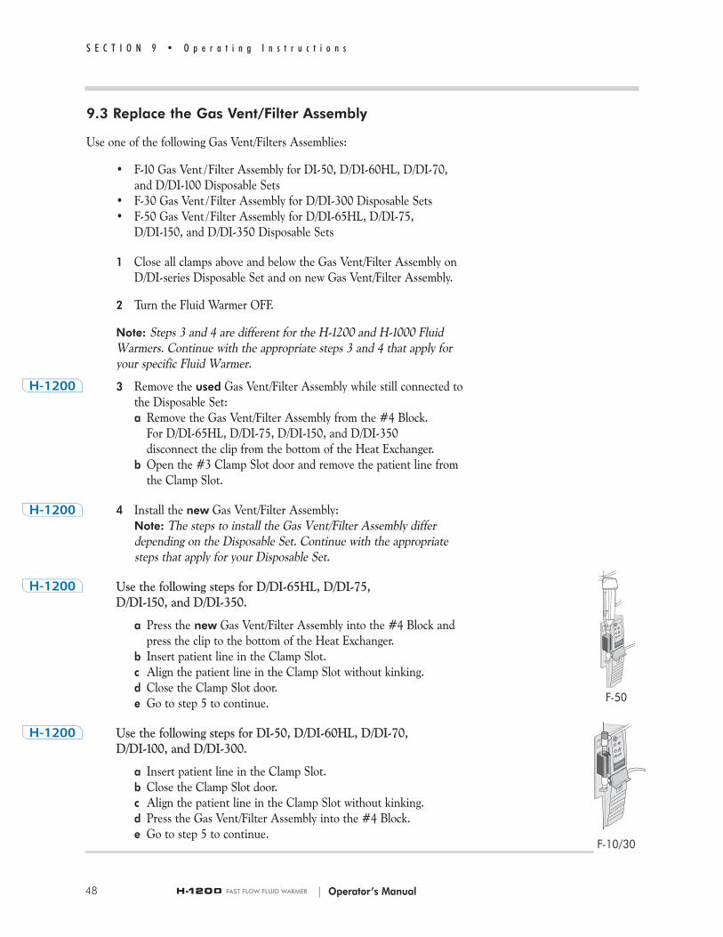
Use the following steps for D/DI-65HL, D/DI-75, D/DI-150, and D/DI-350.
a Press the new Gas Vent/Filter Assembly into the #4 Block and press the clip to the bottom of the Heat Exchanger.
b Insert patient line in the Clamp Slot.c Align the patient line in the Clamp Slot without kinking.d Close the Clamp Slot door.e Go to step 5 to continue.
Use the following steps for DI-50, D/DI-60HL, D/DI-70, D/DI-100, and D/DI-300.
a Insert patient line in the Clamp Slot.b Close the Clamp Slot door.c Align the patient line in the Clamp Slot without kinking.d Press the Gas Vent/Filter Assembly into the #4 Block.e Go to step 5 to continue.
| Operator’s Manual
F-10/30
F-50

49
S E C T I O N 9 • O p e r a t i n g I n s t r u c t i o n s
3 Remove the used Gas Vent/Filter Assembly from the #3 Blockwhile still connected to the Disposable Set.
For D/DI-65HL, D/DI-75, D/DI-150, and D/DI-350 disconnect the clip from the bottom of the Heat Exchanger.
4 Press the new Gas Vent/Filter Assembly into the #3 Block.For D/DI-65HL, D/DI-75, D/DI-150, and D/DI-350 press the clip to the bottom of the Heat Exchanger.
5 Using aseptic technique: a Disconnect the upper Luer fitting on the used Gas Vent/Filter
Assembly.b Remove the upper Luer end cap on the new Gas Vent/Filter
Assembly. c Connect the Disposable Set to the new Gas Vent/Filter Assembly
inlet.
6 With the lower clamp on the new Gas Vent/Filter Assembly closed,open all clamps above Gas Vent/Filter Assembly. The Gas Vent/Filter Assembly will self prime.
7 Turn the power ON.
8 Remove the end cap on the lower patient line of the new GasVent/Filter Assembly. Slowly release the lower clamp and allow thelower patient line to fill completely.
9 Close the clamp after the line is full.
10 Holding the used Gas Vent/Filter Assembly horizontally, disconnectthe Luer lock on the lower patient line. Connect the Luer-lockfittings on the used Gas Vent/Filter Assembly together and discard.
11 Connect the Luer lock on the lower patient line of the GasVent/Filter Assembly to the Patient Line.
12 Open clamps below the Gas Vent/Filter Assembly and resume infusion.
9.4 Activated Alarms
Refer to Section 8, Operation for information on identifying Alarm states,conditions that activate them, and methods for clearing Alarm states.
A. “Air Detected” Alarm mode
Detection of air in the Gas Vent/Filter Assembly results in the following:
• The patient line is clamped off• The red Clamped LED warning signal illuminates• The audible warning signal beeps
| Operator’s Manual
F-50 F-10/30
50
S E C T I O N 9 • O p e r a t i n g I n s t r u c t i o n s
WARNING!
• Activation of the Air Detector/Clamp Alarm during infusion indicates that fluid flow has stopped and that immediate operator intervention is required to restore fluid flow. Failure to reinstate flow (after purging any air or foam) may result in patient death or serious injury.
• Do not turn OFF the Fluid Warmer when the Air Detector alarm is active. If the Fluid Warmer is powered OFF in an active alarmstate, the Air Detector/Clamp will open and the Air Detector will become disabled. This could allow any air within the patient line to be delivered to the patient resulting in serious injury or death.
B. Clear the “Air Detected” Alarm mode:
1 Immediately close all clamps on the Disposable Set
2 Remove pressure from the Pressure Chambers by moving the lever to the minus (–) unpressurized position.
3 Inspect the entire Disposable Set for the presence of air, locate the source of the air, and remove it.
Note: Air or foam may have been vented through the Gas Vent/Filter Assembly.
4 Remove any remaining air from the Disposable Set:a Insert spike into an air-free bag/s of I.V. solution. b Place the I.V. bag/s in the Pressure Chamber/s; close and secure
the door. c Move the lever to the plus (+) pressurized position to
pressurize the Chamber/s.d Prime the drip chamber/s and open the Disposable Set clamps
above the Gas Vent/Filter Assembly.e Fluid flows freely through the tubing. Air in the I.V. line is
vented out through the Gas Vent/Filter Assembly. When air is no longer present in the Gas Vent/Filter Assembly, the Clamp opens and resumes automatic operation mode.
Note: If air is not freely vented, replace the Gas Vent/Filter Assembly.
| Operator’s Manual

51
S E C T I O N 9 • O p e r a t i n g I n s t r u c t i o n s
Refer to Section 9.3, Replace the Gas Vent/Filter Assembly.
5 If no warning signals are active, the Fluid Warmer with Air Detection and Pressure Chambers is ready for use.
6 Open the remaining Disposable Set clamps, slowly open the roller clamp, and reestablish fluid flow to the patient.
For more information on the following alarm conditions, refer to Section 8,Operation:
• Over Temperature Alarm• Check Disposables Alarm• Check Tubing Alarm• Add Recirculating Solution Alarm
9.5 After Use
1 Discontinue infusion.
2 Turn the Fluid Warmer OFF.
3 Release chamber pressure before opening the Pressure Chamber door:a Move the lever to the minus (–) unpressurized position.
This will release the pressure in the chamber and deflate the bladder.
b Open door and remove the fluid bag.
4 Remove the Disposable Set from the Fluid Warmer.
5 Dispose of the Disposable Set in a safe manner according to localguidelines for disposal of contaminated medical waste.
6 Visually check the condition of the device. Remove from service any unit that shows physical damage.
7 Clean the device with warm soapy water.
| Operator’s Manual

S E C T I O N 1 0
Troubleshooting
Only competent personnel should perform any routine maintenance andrepairs to the Level 1® H-1200 Fast Flow Fluid Warmer (Fluid Warmer).
The following two tables feature general troubleshooting information alongwith slow flow rate troubleshooting.
General Troubleshooting Guide
Problem Check the following:
No Power Check to see if unit is plugged in and power is turned ON.Be sure the unit is plugged into a working MAINS receptacle.
Disposables Check to see that the Heat Exchanger and Gas Vent/Filter Alarm beeps Assembly are properly installed.
Add Recirculating Fill reservoir to the maximum reservoir level with recirculating Solution Alarm solution.
Over - If connected to a patient, close all clamps.Temper ature Press OFF button to clear alarm. Then, press ON button to Alarm beeps power on. If the Fluid Warmer continues to alarm, discontinue
use of the medical device and remove from service. Contact Smiths Medical or your local Smiths Medical distributor.
Hot Cabinet Check the air inlet on the bottom of the unit. Remove any blockage or dust to insure adequate air flow.
Heat Exchanger Lubricate O-Rings in #1 and #2 block heat exchanger socketshard to install with silicone lubricant. Silicone lubricant part # 80-04-002.
Loud Compressor Verify pneumatic tubing is fully seated into fittings.
LED doesn’t 1. Verify unit is plugged into MAINS.light up during 2. If still no LED illumination, discontinue use of the medical set up (on Fluid device and remove from service. Warmer or Air Detector/Clamp)
Tubing doesn’t fit Verify tubing is Level 1® D/DI series tubing.in Air Detector/Clamp
| Operator’s Manual52
S E C T I O N 1 0 • T r o u b l e s h o o t i n g

Slow Flow Rate Troubleshooting Guide
Problem Check the following:
Pressure Chambers Verify the Fluid Warmer is ON.not activated Verify the Pressure Chamber levers are fully in the plus (+),
pressurized position.Verify pneumatic tubing is fully seated into fittings on the Pressure Chambers and Fluid Warmer.
Blood develops Stored blood develops particulate. If blood is older particulate than 5-7 days, consider using Level 1® PF-1 pre-filters.
Clogged filter Change Gas Vent/Filter Assembly if filter becomes clogged.
Fluid bag not fully Make sure the membrane of the fluid bag port is fully spiked or bag port pierced by the bag spike and that the neck of the bag port twisted is not twisted.
Non-Level 1® bag 40 to 80 micron filters used between the bag port and port filters the spikes of the Disposable Set may restrict flow. Consider
using Level 1® PF-1 pre-filters (340 micron).
Clamps partly Verify all clamps are fully open.engaged
Clamps left in the Leaving clamps fully clamped for long periods will causeclamped position the tubing to become deformed. Do not leave clampsfor long periods closed for extended periods of time.
Kinked tubing Verify that no tubing kinks are present.
Air trapped on filter Remove Gas Vent/Filter Assembly and tap against the screen of Gas Vent/ cabinet of the Fluid Warmer to dislodge air bubbles, Filter Assembly allowing them to vent. If this fails to correct problem, replace
with new Gas Vent/ Filter Assembly.
Non-high flow Use only extension lines with an inner diameter of extension lines 0.13" (3.3mm) or larger, such as Level 1® X-36 or Y-30
extension sets.
Stopcock Use only Level 1® SC-3 (9 french inner diameter).
Small gauge needle Use large bore needles or catheters to maximize flow or catheter rates.
53
S E C T I O N 1 0 • T r o u b l e s h o o t i n g
| Operator’s Manual

| Operator’s Manual54
S E C T I O N 1 1 • T e s t i n g
S E C T I O N 1 1
Testing
This unit should be tested by hospital biomedical personnel prior to placing itin service. All testing and maintenance should be performed by competentpersonnel. If competent personnel are not available, contact Smiths Medical.If the Level 1® H-1200 Fast Flow Fluid Warmer (Fluid Warmer) and installedaccessories do not pass the tests, discontinue use of the medical device andremove from service. Contact Smiths Medical or your local Smiths Medicaldistributor. Testing requires a Level 1® Disposable Administration Set(Disposable Set) to be installed in the Fluid Warmer.
Add Recirculating Solution Alarm
The Fluid Warmer is equipped with a float switch that senses the levelof the recirculating solution in the reservoir. When the solution level istoo low, an LED on the Display Panel illuminates and an audible alarmbeeps. In the Add Recirculating Solution Alarm mode, the circulatingpump is not running. With a Disposable Set in place and the unitturned on, test the Add Recirculating Solution Alarm by draining thesolution until the level has dropped below the minimum reservoir level.The Add Recirculating Solution Alarm should activate. To drainrecirculating solution from the Fluid Warmer, turn the drain valve, onthe bottom of the unit 90 degrees clockwise and allow some of therecirculating solution to drain into a container.
Check Disposables Alarm
Five Interlocks detect the proper installation of an Disposable Set in theFluid Warmer. If a Disposable Set is not properly installed and thepower is ON, an indicator will illuminate and an audible alarm beeps.With the Fluid Warmer ON, the Interlocks should be tested one at atime by performing the following steps.
1 Top Heat Exchanger Socket – Slide the #2 Block up slowly. The Check Disposables indicator will illuminate and the audible alarm beeps.
2 Heat Exchanger Interlock – Gently pull on the middle of the heat exchanger. The Check Disposables indicator will illuminate and the audible alarm beeps.

a
b
55
S E C T I O N 1 1 • T e s t i n g
3 Gas Vent/Filter Assembly Interlock – Pull the top of the GasVent/Filter Assembly from the Block. The Check Disposablesindicator will illuminate and the audible alarm beeps.
4 #3 Check Tubing Interlock on the Air Detector/Clamp – Removethe tubing from the Clamp Slot and close the door. The CheckTubing alarm signal on the Air Detector/Clamp is activated and theaudible alarm beeps.
5 #3 Check Door Closed Interlock on the Air Detector/Clamp – Withtubing installed in the Clamp Slot, open the door. The CheckTubing alarm signal on the Air Detector/Clamp is activated and theaudible alarm beeps.
Over Temperature Test
Do the following1 Insure that the Fluid Warmer is at operating temperature
(41°C).2 Press and hold the Over Temperature Test button (a). 3 The Over Temperature LEDs illuminate, and an audible alarm
beeps.4 Release the Over Temperature Test button.5 Over Temperature LED and audible alarm signal remains active.
Clear the Alarm mode1 Turn the Fluid Warmer OFF. 2 Turn the Fluid Warmer back ON.
Fluid Warmer Alarm Signal Test
The Alarm Test button is used to confirm proper operation of the visualand audible alarm indicators.
Do the following1 Press and hold the Alarm Test button (b).2 The LED illuminates, and an audible alarm beeps.3 Release the Alarm Test button.4 Over Temperature LED remains lit, and the audible alarm
continues to beep.
Clear the Alarm mode1 Turn the Fluid Warmer OFF.2 Turn the Fluid Warmer back ON.
| Operator’s Manual

| Operator’s Manual56
S E C T I O N 1 1 • T e s t i n g
Performance Testing
Cold Start TestStore the Fluid Warmer unit in a room where the room temperature isapproximately 21°C (70°F).
1 Put a Disposable Set in place. 2 Record the start time.3 Turn the Power button ON.
• The green system operational indicator illuminates.• The Air Detector/Clamp goes through the Power ON Test.• Rapidly rising numbers will appear on the recirculating solution
temperature display.• Within 60 seconds (±) the display should read at least 30°C.• In 3 to 10 minutes the display should read 41°C.
The Temperature Set Point is 41.7°C (+/– 0.3°C).Note: If the Fluid Warmer does not pass the Cold Start Test, it shouldbe removed from use and returned to Smiths Medical or your localSmiths Medical distributor.
Calibration TestOne approved way to confirm proper calibration of the recirculatingsolution temperature is to use the Level 1® Thermal Calibration Well(TCW) (Part Number 80-03-002). A replacement filter (F-10/30 or F-50) must be in place to utilize the TCW.Note: Use of the TCW requires a digital thermometer NIST traceableand accurate within 0.1°C. Required probe size: 0.099" OD (OutsideDiameter) maximum (0.25 cm) 0.50" — 1.50" long (1.27—3.81cm).
Alternative Calibration TestAnother approved way to confirm proper calibration of the recirculatingsolution temperature is to use the Level 1® DSTA-40 TEMPCHECK(Part Number 80-01-040).
Calibration Test with DSTA-40The DSTA-40 TEMPCHECK (DSTA-40) is an electronic thermometerused to verify the recirculating solution operating temperature of theFluid Warmer. The DSTA-40 uses thermistor technology to sense thetemperature of the recirculating solution temperature for the FluidWarmer. The recirculating solution temperature is displayed by a liquidcrystal display (LCD). The DSTA-40 is powered from the auxiliaryoutlet of the Fluid Warmer. No batteries are required.
Note: The Level 1 ® DSTA-40 TEMPCHECK is available for purchase from Smiths Medical.

57
S E C T I O N 1 1 • T e s t i n g
Proper Calibration of Recirculating Solution Temperature Confirm proper calibration of recirculating solution temperature by performing the following steps:
1 Plug the DSTA-40 into the auxiliary outlet located on the bottom of the Fluid Warmer.
2 Install the DSTA-40 in the heat exchanger position (#1 Block and #2 Block).
3 Install a test filter in the #4 Block.
4 Turn the Fluid Warmer ON. Allow to warm up until the DSTA-40 temperature display stabilizes.
5 Compare the DSTA-40 temperature display with the temperature display on the Fluid Warmer’s Display Panel.
Note: The Fluid Warmer’s temperature display must read within 0.3°C of the Level 1® DSTA-40 TEMPCHECK display on a properly calibrated unit.
If the DSTA-40 reads 41.7°C and the Fluid Warmer’s temperature display is within the range of 41.4°C-42.0°C, the calibration is OK.
| Operator’s Manual
| Operator’s Manual
Periodic Electrical Testing
Earth Leakage
The Fluid Warmer must be tested in accordance with EN 60601-1. The earth leakage current test should be performed with the immersionheater circuit in the full ON condition; for this reason the leakage current test should be performed on units which have roomtemperature recirculating solution in the reservoir. Units not meetingthis standard should be returned to Smiths Medical or your local SmithsMedical distributor.
Ground Continuity
The Fluid Warmer must be tested in accordance with EN 60601-1.
WARNING!
Grounding reliability can be achieved only when MAINS powercords are connected to a properly grounded receptacle. Risk ofelectrical shock exists if the equipment is not connected to aproperly grounded receptacle resulting in death or serious injury to the patient or user.
S E C T I O N 1 1 • T e s t i n g
58

| Operator’s Manual
S E C T I O N 1 2
MaintenanceOnly competent personnel should perform any routine maintenance andrepairs to the Level 1® H-1200 Fast Flow Fluid Warmer (Fluid Warmer).Maintenance is scheduled prior to each use, every 30 days, and annually. Thetasks are detailed below.
Note: If distilled water is used as the recirculating solution, change thesolution every 30 days. If a 0.3% hydrogen peroxide/distilled watersolution is used as the recirculating solution, change the solutionevery 12 months, and during the 12 month period, always refill thereservoir with a 0.3% hydrogen peroxide/distilled water solution.
Maintenance Performed Prior to Every Use
Clean and inspect the Fluid Warmer with Air Detector/Clamp andPressure Chambers after each use.
Clean the Exterior
Clean the entire Fluid Warmer after every use.
CAUTIONS
• Never use organic solvents (e.g., acetone), strong acids, or basesto clean any portion of the Fluid Warmer.
• Do not place the Fluid Warmer directly under a faucet or use afaucet sprayer to rinse. Never spray cleaning or other fluids intoopenings on the Fluid Warmer or into the external connectors.
1 Unplug the Fluid Warmer before servicing.
2 Visually inspect the Fluid Warmer to ensure there is no visibledamage or deterioration of the enclosure such as cracks, ordeterioration of the labels and power cord. Do not clean if thereis a defect. Contact Smiths Medical or your local SmithsMedical distributor.
3 Immerse a soft cloth or sponge as an applicator into thecleaning solution consisting of mild liquid detergent soap andwarm tap water mixture. Squeeze out excess solution so that theapplicator is not dripping. Wipe or scrub the entire surface ofthe enclosure and control panels. Use a soft brush to clean thepower cord if necessary.
S E C T I O N 1 2 • M a i n t e n a n c e
59

| Operator’s Manual
4 Rinse a separate soft cloth or sponge in room temperaturerunning potable water. Squeeze out excess water so that theapplicator is not dripping. Wipe all of the aforementionedsurfaces. Repeat rinsing the cloth or sponge several times withfresh running water during this process to insure all visibleresidue is removed.
5 Dry the item with a hand towel or soft cloth.
6 Visually inspect the Fluid Warmer and its components to insurethat they have been thoroughly cleaned. Repeat cleaningprocedure if necessary.
7 After thoroughly cleaning the Fluid Warmer, performdisinfection if required.
8 If it is hospital policy to perform disinfection as part ofreprocessing, then follow your institution’s guidelines fordisinfecting of the surfaces of non-critical medical devices. Thelist below includes low-level disinfectants that are commonly usedin the medical community and high-level disinfectants that areclaimed by the manufacturer. The effectiveness of these listeddisinfectants should be validated using the hospital procedures.
The following disinfectant agents can be used without causingdamage to the enclosure:
Low Level Disinfectants:
• fantastik® All Purpose Cleaner
High Level Disinfectants:
• 1.59% Phenol (e.g., Sporicidin®)• 3.4% Glutaraldehyde (e.g., CIDEX® Plus)• 10% Bleach solution• 1% Ammonia solution• Surface disinfectants compatible with plastic or metal materials
9 Rinsing of the disinfectant residue should be done using a soft cloth or sponge as the applicator.
General Inspection
• Check the condition of the Fluid Warmer with a visual inspection. Remove from service any unit that shows physical damage.
• If the Disposable Set does not install easily, lubricate the O-Ringsas directed in the following section.
S E C T I O N 1 2 • M a i n t e n a n c e
60

| Operator’s Manual
Maintenance Performed Every 30 Days
Lubricate O-Ring Seals
It is not necessary to disassemble the blocks to lubricate the O-Rings.
1 Place a small amount of silicone grease on a cotton swab.
2 Apply the silicone grease along the O-Rings in the bottom #1 Block, and top #2 Block Heat Exchanger sockets.
Change Recirculating Solution with Distilled Water
1 Place a container under the drain valve of the Fluid Warmer.
2 Drain the recirculating solution by turning the drain valve clockwise 90 degrees.
3 When all solution has drained from the reservoir, close the drain valve.
4 Refill the reservoir with distilled water. The reservoir holds 1.4 liters.
Maintenance Performed Every 12 Months
Disinfect the Reservoir
1 Place a container under the drain valve of the Fluid Warmer.
2 Drain the recirculating solution by turning the drain valveclockwise 90 degrees.
3 When all solution has drained from the reservoir, close the drain valve.
4 Remove the fill-port plug on the reservoir.
5 Prepare a 0.3% hydrogen peroxide/distilled water solution. Mix140 ml of 3% hydrogen peroxide solution and 1,260 ml ofdistilled water.
6 Fill the reservoir with 1.4 liters of 0.3% hydrogenperoxide/distilled water solution.
7 Replace the fill-port plug.
8 Insert a Disposable Set into the Fluid Warmer.
61
S E C T I O N 1 2 • M a i n t e n a n c e

9 Turn the Fluid Warmer ON. Let the solution circulate for a 30-minute disinfection period.
10 Turn the Fluid Warmer OFF.
11 Empty the reservoir.
12 Remove the Disposable Set and discard according to establishedhospital procedures
Change Recirculating Solution with a 0.3% HydrogenPeroxide/Distilled Water Solution
1 Place a container under the drain valve of the Fluid Warmer.
2 Drain the recirculating solution by turning the drain valveclockwise 90 degrees.
3 When all the solution has drained from the reservoir, close thedrain valve.
4 Prepare a 0.3% hydrogen peroxide/distilled water solution. Mix140 ml of 3% hydrogen peroxide solution and 1,260 ml ofdistilled water.
5 Fill the reservoir with 0.3% hydrogen peroxide/distilled watersolution. The reservoir holds 1.4 liters.
Change O-Rings
Change the O-Rings in the #1 Block and #2 Block.
1 Remove each O-Ring from its socket by pulling it out with a pair of needle-nose pliers or by prying it out with a small screwdriver.
2 Lubricate the new O-Rings from the O-Ring Kit.
3 Press each O-Ring into its socket.
Clean Fan Filter
The Fan Filter (a) is located on the bottom of the Fluid Warmer. The fan guard snaps in place.
1 Remove four screws and unsnap the fan guard from the bottom of the unit.
2 Clean the filter with warm soapy water.
3 Replace the fan guard and filter.
S E C T I O N 1 2 • M a i n t e n a n c e
| Operator’s Manual62
a
| Operator’s Manual
Inspect Air Detector/Clamp
1 Check Clamp Cover Door for proper closure.
2 Check the Clamp Cover Door, Clamp Slot and Detector Head for structural integrity.
Testing Fluid Warmer Operation
Perform all the tests described in the testing section of this manual. See Section 11, Testing.
• Add Recirculating Solution Alarm• Check Disposables Alarm• Over Temperature Alarm• Performance Testing
S E C T I O N 1 2 • M a i n t e n a n c e
63
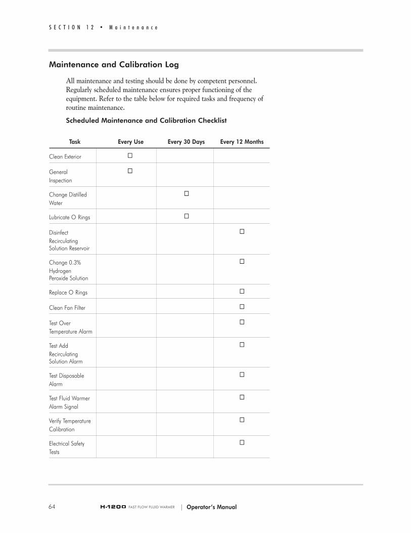
Maintenance and Calibration Log
All maintenance and testing should be done by competent personnel.Regularly scheduled maintenance ensures proper functioning of theequipment. Refer to the table below for required tasks and frequency ofroutine maintenance.
Scheduled Maintenance and Calibration Checklist
Task Every Use Every 30 Days Every 12 Months
Clean Exterior 9
General 9Inspection
Change Distilled 9Water
Lubricate O Rings 9
Disinfect 9Recirculating Solution Reservoir
Change 0.3% 9Hydrogen Peroxide Solution
Replace O Rings 9
Clean Fan Filter 9
Test Over 9Temperature Alarm
Test Add 9Recirculating Solution Alarm
Test Disposable 9Alarm
Test Fluid Warmer 9Alarm Signal
Verify Temperature 9Calibration
Electrical Safety 9Tests
S E C T I O N 1 2 • M a i n t e n a n c e
64 | Operator’s Manual

| Operator’s Manual 65
S E C T I O N 1 3 • L i m i t e d W a r r a n t y
S E C T I O N 1 3
Limited Warranty
Smiths Medical ASD, Inc. (the “Manufacturer”) warrants to the OriginalPurchaser that the Level 1® H-1200 Fast Flow Fluid Warmer, not includingaccessories, shall be free from defects in materials and workmanship undernormal use, if used in accordance with this Operator’s Manual, for a period ofone year from the actual date of sale to the Original Purchaser. THERE ARENO OTHER WARRANTIES.
This warranty does not cover normal wear and tear and maintenance items,and excludes any accessory items or equipment used with the Level 1® H-1200Fast Flow Fluid Warmer.
Subject to the conditions of and upon compliance with this Limited Warranty,the Manufacturer will repair or replace at its option without charge (exceptfor a minimal charge for postage and handling) any Level 1® H-1200 Fast FlowFluid Warmer (not including accessories) which is defective if a claim is madeduring such one-year period.
The following conditions, procedures, and limitations apply to theManufacturer's obligation under this warranty:
A. Parties Covered by this Warranty: This warranty extends only to theOriginal Purchaser of the Level 1® H-1200 Fast Flow Fluid Warmer. Thiswarranty does not extend to subsequent purchasers. The OriginalPurchaser may be medical personnel, a hospital, or institution whichpurchases Level 1® H-1200 Fast Flow Fluid Warmer for treatment ofpatients. The Original Purchaser should retain the invoice or salesreceipt as proof as to the actual date of purchase.
B. Warranty Performance Procedure: Notice of the claimed defect must bemade in writing or by telephone to the Manufacturer as follows:Customer Service Department, Smiths Medical ASD, Inc., 160Weymouth Street, Rockland, MA 02370, (800) 258-5361. Notice to theManufacturer must include date of purchase, model and serial number,and a description of the claimed defect in sufficient detail to allow theManufacturer to determine and facilitate any repairs which may benecessary. AUTHORIZATION MUST BE OBTAINED PRIOR TORETURNING THE LEVEL 1® H-1200 FAST FLOW FLUIDWARMER. If authorized, the Level 1® H-1200 Fast Flow Fluid Warmermust be properly and carefully packaged and returned to theManufacturer, postage prepaid. Any loss or damage during shipment is atthe risk of the sender.

66
S E C T I O N 1 3 • L i m i t e d W a r r a n t y
C. Conditions of Warranty: The warranty is void if the Level 1® H-1200Fast Flow Fluid Warmer has been 1) repaired by someone other thanthe Manufacturer or its authorized agent; 2) altered so that its stabilityor reliability is affected; 3) misused; or 4) damaged by negligence oraccident. Misuse includes, but is not limited to, use not in compliancewith the Operator's Manual or use with non-approved accessories.Removal or damage to the Level 1® H-1200 Fast Flow Fluid Warmerserial numbers will invalidate this warranty.
D. Limitations and Exclusions: Repair or replacement of the Level 1®
H-1200 Fast Flow Fluid Warmer or any component part thereof is theEXCLUSIVE remedy offered by the Manufacturer. The followingexclusions and limitations shall apply:
1. No agent, representative, or employee of the Manufacturer hasauthority to bind the Manufacturer to any representation orwarranty, expressed or implied.
2. THERE IS NO WARRANTY OF MERCHANTABILITY ORFITNESS OR USE OF THE LEVEL 1® H-1200 FAST FLOWFLUID WARMER FOR ANY PARTICULAR PURPOSE.
3. The Level 1® H-1200 Fast Flow Fluid Warmer can only be usedunder the supervision of medical personnel whose skill andjudgment determine the suitability of the Level 1® H-1200 Fast FlowFluid Warmer for any particular medical treatment.
4. All recommendations, information, and descriptive literaturesupplied by the Manufacturer or its agents are believed to beaccurate and reliable, but do not constitute warranties.
The Manufacturer disclaims responsibility for the suitability of the Level 1®
H-1200 Fast Flow Fluid Warmer for any particular medical treatment or forany medical complications resulting from the use of the Level 1® H-1200 FastFlow Fluid Warmer. The Manufacturer shall not be responsible for anyincidental damages or consequential damages to property, loss of profits, orloss of use caused by any defect or malfunction of the Level 1® H-1200 FastFlow Fluid Warmer..
This warranty gives the Original Purchaser specific legal rights, and theOriginal Purchaser may have other legal rights which may vary from state tostate.
| Operator’s Manual

S E C T I O N 1 4
Service
WARNING!
• No user-serviceable parts. All service must be performed bySmiths Medical or competent personnel.
All service must be performed by Smiths Medical or competent personnel.Service by any other person or organization voids the warranty and transfersliability for malfunctions of the device to the servicing organization.
Warranty Service
Units received for repair which have not been obviously abused orimpact damaged and are still under warranty will be promptly repairedand returned at no charge. See the limited warranty section of thismanual. A no-charge purchase order is requested for tracking.
Non-Warranty Work
Units received that are no longer under warranty can be returned forrepair for a cost. The unit will be promptly inspected and a verbalestimate of the repair cost will be provided. A purchase order will berequired from the original purchaser consistent with the verbal estimate.A written estimate will be provided upon request.
Before returning your Level 1® H-1200 Fast Flow Fluid Warmer (FluidWarmer) or Level 1® H-31, Version B, Air Detector/Clamp for service,contact Smiths Medical for Returned Goods Authorization. Be sure thatALL recirculating solution is drained from the unit before packing theFluid Warmer for shipment.
Note: The Fluid Warmer must be cleaned and disinfected for repair shipment or it will be immediately returned as received.
Additional Documentation
Upon request Smiths Medical will provide the following documentation:• Circuit diagrams
67
S E C T I O N 1 4 • S e r v i c e
| Operator’s Manual

• Components parts list(s)• Description of function• Service and calibration instructions
Disposal Information
Observe national and local codes or requirements for disposal ofcontaminated materials and for recycling solid waste materials that mayimpact the environment.
Service Contacts
Contact your Smiths Medical Technical Service Department or SmithsMedical distributor at:
USA/Canada
Smiths Medical ASD, Inc.160 Weymouth StreetRockland, MA 02370 USAUSA/Canada 1-800-258-5361International +1-781-878-8011
European Representative
Smiths Medical International Ltd Colonial Way, Watford,Herts, WD24 4LG, UKTel +44 (0) 1923 246434Fax +44 (0) 1923 240273
Australian Representative
Smiths Medical Australasia Pty. Ltd.61 Brandl StreetEight Mile Plains, QLD 4113, AustraliaTel +61 (0) 7 3340 1300Fax +61 (0) 7 3340 1399
New Zealand
Tel 0 800 444 200
www.smiths-medical.com
| Operator’s Manual
S E C T I O N 1 4 • S e r v i c e
68
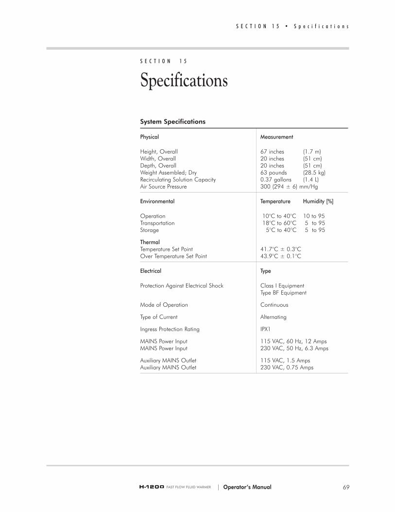
S E C T I O N 1 5 • S p e c i f i c a t i o n s
| Operator’s Manual 69
S E C T I O N 1 5
Specifications
System Specifications
Physical Measurement
Height, Overall 67 inches (1.7 m)Width, Overall 20 inches (51 cm)Depth, Overall 20 inches (51 cm)Weight Assembled; Dry 63 pounds (28.5 kg)Recirculating Solution Capacity 0.37 gallons (1.4 L)Air Source Pressure 300 (294 ± 6) mm/Hg
Environmental Temperature Humidity [%]
Operation 10°C to 40°C 10 to 95Transportation 18°C to 60°C 5 to 95Storage 5°C to 40°C 5 to 95
ThermalTemperature Set Point 41.7°C ± 0.3°COver Temperature Set Point 43.9°C ± 0.1°C
Electrical Type
Protection Against Electrical Shock Class I Equipment Type BF Equipment
Mode of Operation Continuous
Type of Current Alternating
Ingress Protection Rating IPX1
MAINS Power Input 115 VAC, 60 Hz, 12 AmpsMAINS Power Input 230 VAC, 50 Hz, 6.3 Amps
Auxiliary MAINS Outlet 115 VAC, 1.5 AmpsAuxiliary MAINS Outlet 230 VAC, 0.75 Amps

70
S E C T I O N 1 5 • S p e c i f i c a t i o n s
Electromagnetic Environment Recommendations
Disposable Administration Set Specifications
DI-50Filter Size 170 MicronPriming Volume
DI 50 56 mlSystem 1200 Normothermic (35 41°C)
Fluid Delivery Range10°C Input: 40 ml/min. to 300 ml/min.20°C Input: 40 ml/min. to 400 ml/min.
Maximum Flow Rate 500 ml/min.(crystalloid, 300 mmHg, 14g catheter)
D/DI-60HL and D/DI-65HLFilter Size 170 MicronPriming Volume
D/DI 60HL 74 mlD/DI 65HL 164 ml
System 1200 Normothermic (35 41°C) Fluid Delivery Range
10°C Input: 75 ml/hour to 530 ml/min.20°C Input: 75 ml/hour to 530 ml/min.
Maximum Flow Rate 530 ml/min.(crystalloid, 300 mmHg, 8.5 F catheter)
| Operator’s Manual
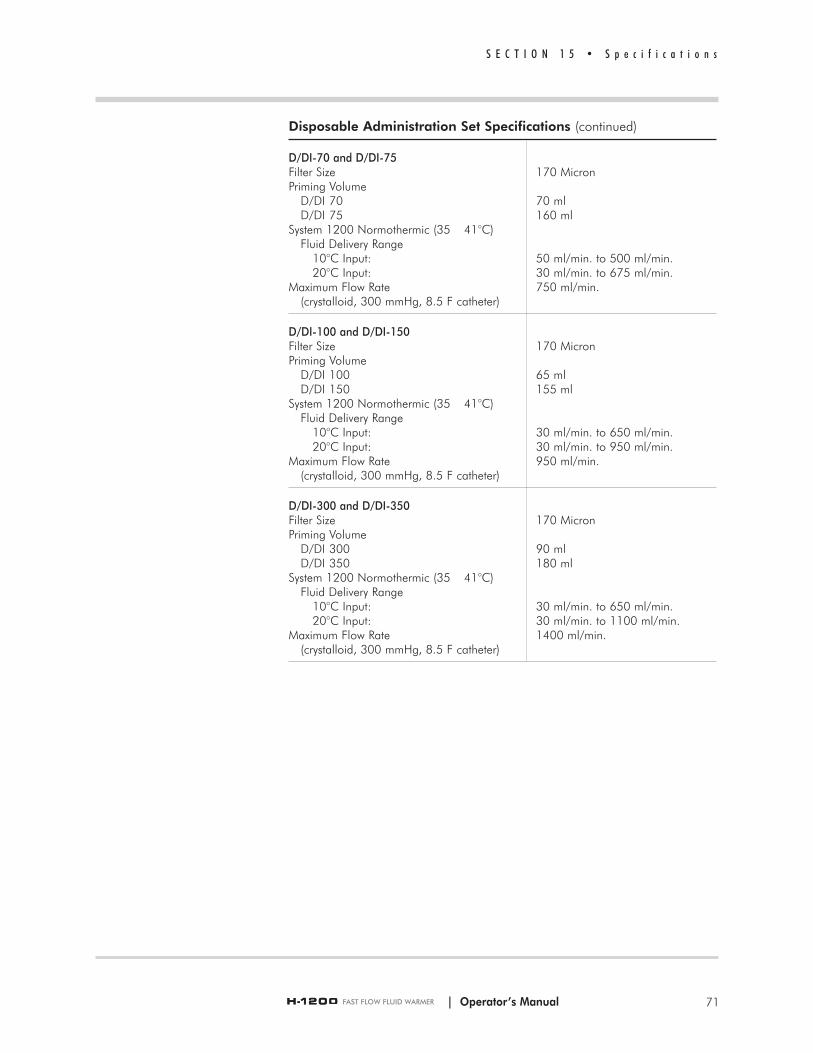
Disposable Administration Set Specifications (continued)
D/DI-70 and D/DI-75Filter Size 170 MicronPriming Volume
D/DI 70 70 mlD/DI 75 160 ml
System 1200 Normothermic (35 41°C) Fluid Delivery Range
10°C Input: 50 ml/min. to 500 ml/min.20°C Input: 30 ml/min. to 675 ml/min.
Maximum Flow Rate 750 ml/min.(crystalloid, 300 mmHg, 8.5 F catheter)
D/DI-100 and D/DI-150Filter Size 170 MicronPriming Volume
D/DI 100 65 mlD/DI 150 155 ml
System 1200 Normothermic (35 41°C) Fluid Delivery Range
10°C Input: 30 ml/min. to 650 ml/min.20°C Input: 30 ml/min. to 950 ml/min.
Maximum Flow Rate 950 ml/min.(crystalloid, 300 mmHg, 8.5 F catheter)
D/DI-300 and D/DI-350Filter Size 170 MicronPriming Volume
D/DI 300 90 mlD/DI 350 180 ml
System 1200 Normothermic (35 41°C) Fluid Delivery Range
10°C Input: 30 ml/min. to 650 ml/min.20°C Input: 30 ml/min. to 1100 ml/min.
Maximum Flow Rate 1400 ml/min.(crystalloid, 300 mmHg, 8.5 F catheter)
S E C T I O N 1 5 • S p e c i f i c a t i o n s
71| Operator’s Manual

| Operator’s Manual
S E C T I O N 1 6
Symbols
S E C T I O N 1 6 • S y m b o l s
72

S E C T I O N 1 6 • S y m b o l s
| Operator’s Manual 73

Alarm Test
ON Only for a part of the equipment. MAINS are connected
OFF Only for a part of the equipment. The MAINS are still connected
Automatic Operation
Recirculating Solution Temperature
Over Temperature Test(Recirculating Solution Over Temperature)
Add Recirculating Solution
Check Disposables, Check Tubing
Clamped
Maximum Reservoir Level
Minimum Reservoir Level
Device has been tested by National Technical Systems, a nationally recognized technical lab, to meet U.S. requirements for safety.
CE Mark and Notified Body number(0473 indicates AMTAC)
Humidity Limitation
Symbol Meaning
0 4 7 30 4 7 3
%95%
5%
Collect separately for electrical and electronic equipment.
Contains or Presence of Phthalate: bis(2 ethylhexyl) phthalate (DEHP)‚
S E C T I O N 1 6 • S y m b o l s
| Operator’s Manual74

I n d e x
| Operator’s Manual 75
AAdd Recirculating Solution indicator 23Add Recirculating Solution Mode 32After Use 51Air Detected Alarm mode
Clear 50Detected 49
Air Detected/Clamped Mode 35Air Detection /Clamp
Description 3Principles of operation 19Air Detector/Clamp Control Panel 24
Alarm Test Mode 31Alarms
Add Recirculating Solution 32Air Detected 49Air detected/Clamped 35Check Disposables 32Check Tubing 34Over Temperature 33Summary table 28
Assembly instructions 9Disinfect recirculating solution
reservoir 13Fluid Warmer 9H-31, B Air Detector/Clamp 15
Automatic Operation Air Detector/Clamp 34
Automatic Operation indicatorAir Detector/Clamp 23Fluid Warmer 24
BButton functions 22
CCalibration of recirculating solution
temperature 57Change O-Rings 62Change recirculating solution
Distilled water 610.3% hydrogen peroxide/distilled
water solution 62Check Disposables indicator 23Check Disposables Mode 32Check Tubing indicator 24Check Tubing Mode 34Clamped indicator 24Clean fan filter 62Clean the exterior 59Components list 10Contraindications 5Controls and displays 21
DDescription 3
Air Detector/Clamp 3Disposable Administration Set 3Fluid Warmer 3Pressure Chambers 3
Disinfect recirculating solution reservoir 61During assembly 13
Disposable Administration SetDescription 3Install 38Prime 41
Disposal information 68Drain valve 11DSTA-40 calibration test 56
EElectrical safety tests 17Electrical testing 58Electromagnetic Environment
Recommendations 70
FF-50 Gas Vent/Filter Assembly 20Flanking brackets 12Fluid Bag
Change 47Fluid Warmer
Description 3Principles of operation 19Use of 46
Fluid Warmer Alarm Signal Test button 22
Fluid Warmer Display Panel 23
GGround continuity 58
HH-31, B Air Detector/Clamp
Assembly instructions 15
IIndications for use 4Interlocks for Disposable Set
installation 26
LLog
Maintenance and calibration 64Lubricate O-Ring seals 61
MMaintenance 59
Every 12 months 61Every 30 days 61Log/Schedule 64Prior to every use 59
Modes of Operation 30Add Recirculating Solution Mode 32Air Detected/Clamped Mode 35Alarm Test Mode 31Automatic Operation Air
Detector/Clamp 34Check Disposables Mode 32Check Tubing Mode 34OFF Mode 30ON/Automatic Operation for Fluid
Warmer 30Over Temperature Alarm Mode 33Over Temperature Test Mode 31Power ON Test for Air
Detector/Clamp 33Pressurized Mode 35Unpressurized Mode 36
OOFF Mode 30ON/Automatic Operation for Fluid
Warmer 30Operating Instructions 37Operation Display/Panel summary 28O-Rings
Lubricate 61Over Temperature Alarm Mode 33Over Temperature indicator 23Over Temperature Test button 22Over Temperature Test Mode 31
PPanels
Air Detector/Clamp Control 24Fluid Warmer Display 23Power and Alarm Test 22Pressure Chamber control 25
Performance testing 56Pneumatic tubing 14Power and Alarm Test Panel 22Power OFF button 22Power ON button 22Power ON Test for Air Detector/Clamp 33Pressure Chamber Control Panel 25Pressure Chambers
Description 3Install 12Load for use 46Pressurize for use 46Principles of operation 19

Pressure gauge 25Pressurize Pressure Chambers 46Pressurize/Unpressurize lever 25Pressurized Mode 35Prime
Disposable Administration Set 41Patient Line 42
Principles of operation 19
QQuick Reference Guide 10, 12
RRecirculating solution temperature
calibration 57Recirculating Solution Temperature
display 23Replace Gas Vent/Filter Assembly 48Reservoir Capacity 22Reservoir level display 23
SSafety information 5Service information 67
contacts 68Set Up for use 38Specifications 69
Disposable Set 70system 69
Symbols 72
TTEMPCHECK calibration test 56Temperature Display 23, 31Test Air Detector/Clamp 44Test Fluid Warmer Alarms 43Testing 54
Add Recirculating Solution Alarm 54Air Detector/Clamp 44Check Disposables Alarm 54Electrical 58Fluid Warmer Alarm 55Ground continuity 58Maintenance requirement 59
Over Temperature test 55Performance 56
TroubleshootingGeneral 52Slow flow rate 53
UUnpressurized Mode 36
WWarranty information 65
I n d e x
| Operator’s Manual76

s
lTM
Manufacturer:Smiths Medical ASD, Inc.160 Weymouth StreetRockland, MA 02370, USAUSA/Canada: 1-800-258-5361International: +1-781-878-8011
Made in USA
Australian Representative:Smiths Medical Australasia Pty. Ltd.61 Brandl StreetEight Mile Plains, QLD 4113, AustraliaTel AU: +61 (0) 7 3340 1300 Tel NZ: 0 800 444 200
European Representative:Smiths Medical International Ltd.Colonial WayWatford, Herts, WD24 4LG, UKTel: +44 (0) 1923 246434
www.smiths-medical.com