tm 9-1040-267-20&p - liberatedmanuals.com · change no. 1 tm 9-1040-267-20&p c1...
TRANSCRIPT

TM 9-1040-267-20&PTECHNICAL MANUAL
ORGANIZATIONAL MAINTENANCE MANUAL(INCLUDING REPAIR PARTS AND SPECIAL TOOLS LIST)
FOR
LAUNCHER, GRENADE, SMOKE: SCREENING, RP, M243(1040-01-059-0560)
LAUNCHER, GRENADE, SMOKE: SCREENING, RP, M257(1040-01-070-1213)
ANDLAUNCHER, GRENADE, SMOKE: SCREENING, RP, M259
(1040-01-107-7501)
HEADQUARTERS, DEPARTMENT OF THE ARMY
FEBRUARY 1984

FIRST AIDFor first aid information, refer to FM 21-11 (TEST)

CHANGE
No. 1
TM 9-1040-267-20&PC1
HEADQUARTERSDEPARTMENT OF THE ARMY
Washington, DC 9 December 1987
TECHNICAL MANUALORGANIZATIONAL MAINTENANCE MANUAL
(INCLUDING REPAIR PARTS AND SPECIAL TOOLS LIST)
FOR
LAUNCHER, GRENADE, SMOKE: SCREENING, RP, M243(1040-01-059-0560)
LAUNCHER, GRENADE, SMOKE: SCREENING, RP, M257(1040-01-070-1213)
ANDLAUNCHER, GRENADE, SMOKE: SCREENING, RP, M259
(1040-01-107-7501)
TM 9-1040-267-20&P, 1 February 1984, is changed as follows:
1. Remove old pages and insert new pages as indicated below.
2. New or changed material is indicated by a vertical bar in the margin of the page.
3. New or changed illustrations are indicated by a miniature pointing hand highlightingthe change.
Remove Pages Insert Pages
i and ii(V blank)/1-01-1 through 1-42-3 and 2-42-51 through 2-54A-1 and A-2B-3 and B-4C-7 through C-16Index-1 and Index-2
i and ii(v blank)/1-01-1 through 1-42-3 and 2-42-51 through 2-54A-1 and A-2B-3 and B-4C-7 through C-16Index-1 and Index-2
File this sheet in the back of the publication: for reference purposes.

TM 9-1040-267-20&P
By Order of the Secretary of the Army:
JOHN A. WICKHAM, JR.General, United States Army
Chief of Staff
Official:
ROBERT M. JOYCEMajor General, United States ArmyThe Adjutant General
DISTRIBUTION:
To be distributed in accordance with DA Form 12-28, Organizational MaintenanceRequirements for Munitions, Chemical Launchers.

TECHNICAL MANUAL
NO. 9-1040-267-20&P
HEADQUARTERSDEPARTMENT OF THE ARMY
Washington, DC, 1 February 1984Organizational Maintenance Manual
(Including Repair Parts and Special Tools List)for
LAUNCHER, GRENADE, SMOKE: SCREENING, RP, M243(1040-01-0590560)
LAUNCHER, GRENADE, SMOKE: SCREENING, RP, M257(1040-01-070-1213)
ANDLAUNCHER, GRENADE, SMOKE: SCREENING, RP, M259
(1040-01-107-7501)
Current as of April 1987 for appendix C .
REPORTING ERRORS AND RECOMMENDING IMPROVEMENTS
You can help improve this manual. If you find any mistakes or if you know of a way to improve theprocedures, please let us know. Mail your letter, DA Form 2028 (Recommended Changes to Publica-tions and Blank Forms), or DA Form 2028-2 located in the back of this manual direct to: Commander,US Army Armament, Munitions and Chemical Command, ATTN: AMSMC-MAS, Rock Island, IL61299-6000. A reply will be furnished to you.
PageHOW TO USE THIS MANUAL . . . . . . . . . . . . . . . . . . . . . . . . . . . . . . . . . . . . . . . . . . ... .iii
CHAPTER 1 INTRODUCTION . . . . . . . . . . . . . . . . . . . . . . . . . . . . . . . . . . . . . . . . . . . . . . . . . . . . . . . . .. 1-1Section I. General Information . . . . . . . . . . . . . . . . . . . . . . . . . . . . . . . . . ....................1-1Section Il. Equipment Description and Data... . . . . . . . . . . . . . . . . . . . . . . . . . . . . . . . . . .. . ...1-2Section Ill. Principles of Operation . . . . . . . . . . . . . . . . . . . . . . . . . . . . . . . . . . . . . . . . . . . . . . . ...1-4
CHAPTER 2 MAINTENANCE INSTRUCTIONS . . . . . . . . . . . . . . . . . . . . . . . . . . . . . . . . ... .......2-1Section I. Repair Parts, Special Tools, TMDE, and Support Equipment . . . . . . . . . . . . . . ...2-1
* This manual supersedes TM 3-1040-267-20&P, dated 30 December 1981.
i Change 1 *TM 9-1040-267-20&P

iiTM 9-1040-267-20&P
IllusPage Figure
Section Il. Service Upon Receipt . . . . . . . . . . . . . . . . . . . . . . . . . . . . . . . . . . . . . . . . . . . . . . . . ... 2-1
Section Ill. Preventive Maintenance Checks and Services (PMCS) . . . . . . . . . . . . . . . . . . . ...2-5
Section IV. Troubleshooting . . . . . . . . . . . . . . . . . . . . . . . . . . . . . . . . . . . . . . . . . . . . . . . . . . . . . . ...2-5
Section V. Maintenance Procedures . . . . . . . . . . . . . . . . . . . . . . . . . . . . . . . . . . . . . . . . . . . . . . ...2-14
Section VI. Preparation for Storage or Shipment . . . . . . . . . . . . . . . . . . . . . . . . . . . . . . . . . . . ...2-54
APPENDIX A REFERENCES . . . . . . . . . . . . . . . . . . . . . . . . . . . . . . . . . . . . . . . . . . . . . . . . . . . . . . . . . ..A-1
APPENDIX B MAINTENANCE ALLOCATION CHART . . . . . . . . . . . . . . . . . . . . . . . . . . . . . . . . ...B-1
Section I. Introduction . . . . . . . . . . . . . . . . . . . . . . . . . . . . . . . . . . . . . . . . . . . . . . . . . . . . . . . . . ...B-1Section Il. Maintenance Allocation Chart... . . . . . . . . . . . . . . . . . . . . . . . . . . . . . . . . . . . . . . . ...B-3Section Ill. Tool and Test Equipment Requirements . . . . . . . . . . . . . . . . . . . . . . . . . . . . . . . . ...B-4Section IV. Remarks . . . . . . . . . . . . . . . . . . . . . . . . . . . . . . . . . . . . . . . . . . . . . . . . . . . . . . . . . . . . . ..B-4
APPENDIX C REPAIR PARTS AND SPECIAL TOOLS LIST . . . . . . . . . . . . . . . . . . . . . . . . . . . . . . C1
Section I.Section Il.Group 00Group 01Group 02Group 03Group 0999Section III.Section IV.
Introduction . . . . . . . . . . . . . . . . . . . . . . . . . . . . . . . . . . . . . . . . . . . . . . . . . . . . . . . . . . . C-1Repair Parts List . . . . . . . . . . . . . . . . . . . . . . . . . . . . . . . . . . . . . . . . . . . . . . . . . . . . . . . C-8Launcher, Grenade, Smoke: M243, M257, and M259 . . . . . . . . . . . . . . . . . . . . . . C-9 C-1Discharger, Smoke: Grenade . . . . . . . . . . . . . . . . . . . . . . . . . . . . . . . . . . . . . . . . . . . ..C-11 C-2Arming Firing Unit: Grenade Discharger . . . . . . . . . . . . . . . . . . . . . . . . . . . . . . . . . . C-13 C-3Box, Vehicular Accessories Storage: Smoke Grenade . . . . . . . . . . . . . . . . . . . . . . C-14 C-4Bulk Material . . . . . . . . . . . . . . . . . . . . . . . . . . . . . . . . . . . . . . . . . . . . . . . . . . . . . . . . . . C-15Special Tools List (Nonapplicable) . . . . . . . . . . . . . . . . . . . . . . . . . . . . . . . . . . . . . . . C-15National Stock Number and Part Number Index . . . . . . . . . . . . . . . . . . . . . . . . . . . C-16
APPENDIX D EXPENDABLE/DURABLE SUPPLIES AND MATERIALS LIST . . . . . . . . . . . ..D-1
Section l. Introduction . . . . . . . . . . . . . . . . . . . . . . . . . . . . . . . . . . . . . . . . . . . . . . . . . . . . . . . . . . ..D-lSection Il. Expendable/Durabie Supplies and Materials List . . . . . . . . . . . . . . . . . . . . . . . . . . . D-1
ALPHABETICAL INDEX Index-1

HOW TO USE THIS MANUAL
GENERAL MAINTENANCE INSTRUCTIONS
When using this manual, you should know:
a.
b.
c.
d.
The launchers are either being prepared for installation on vehicles orhave been removed for maintenance.The procedures for mounting or removing this equipment from vehiclesare in the vehicles’ organizational maintenance manuals.You must familiarize yourself with the entire maintenance proceduresbefore beginning the maintenance task.References are to pages, paragraphs, or other publications.
INDEXES
For quick access to parts of this manual, there are four indexes.
a.
b.
c.
d.
Front Cover Index. Important sections and appendixes are tabbed.Tabs are keyed to page locations.Table of Contents. Lists in order all chapters, sections, and appendixes.Gives page references.Maintenance Action Precise Symptom (MAPS) List (table 2-1). Listslauncher parts and symptoms of faults that maybe detected and isolatedby troubleshooting. Refers to pages of troubleshooting table 2-2.Alphabetical Index. Lists page numbers for each paragraph and EXAMPLEappendix.
INTRODUCTION
Chapter 1 describes the launchers and their principles of operation.
. . .iii
Chapter 2 covers:
a.
b.
c.
d.
Service Upon Receipt. Gives procedures for servicing launchers uponreceipt.Troubleshooting. Provides detailed illustrated procedures for trou-bleshooting discharger and arming firing unit.Maintenance Procedures. Provides initial setup and detailed proce-dures for performing maintenance functions authorized by the mainte-nance allocation chart (MAC), appendix B.Preparation for Storage or Shipment. Gives criteria for storing or ship-ping launchers.
APPENDIXES
The appendixes contain:
a. A list of all references usedb. The MACc. The RPSTL with illustrationsd. A list of expendable supplies you’ll need
You have received a launcher or one of its major components for repair.
a. How do you start?Look at the front cover of this manual. At the bottom you will find the listing“Troubleshooting,” telling you to go to page 2-5. Below the page numberis a black tab or bleed mark. A corresponding black mark is located onpage 2-5.
TM 9-1040-267-20&P

iv
TM 9-1040-267-20&P
b. What symptom does your launcher have?Look at the Maintenance Action Precise Symptom (MAPS) List in table2-1. If, for example, the discharger won’t fire, the MAPS List refers you toMalfunction 1 in Table 2-2, Troubleshooting Procedures.
c. How do you fix a problem?Follow the instructions in the troubleshooting table. The readings you geton your multi meter will help you to find the fault. If you get a faulty reading
while doing a step, the instructions under corrective action tell you whatmaintenance procedure to follow and the paragraph number. Follow theprocedures until the problem is fixed.
d. What supplies and equipment will you need?Go to the alphabetical index in the back of the manual. Look for the majorcomponent you are going to fix, for example, discharger maintenanceinstructions which refers you to page 2-14. There you will find a list of testequipment, tools, and materials and mandatory parts that you will need.


(v blank)/1-0 Change 1
DISCHARGER, SMOKE: GRENADE
M243 LAUNCHER
M257 LAUNCHER
M259 LAUNCHER
CAP-PLUG, PROTECTIVE, DUSTAND MOISTURE SEAL: DISCHARGER
M243 LAUNCHER
M257 LAUNCHER
M259 LAUNCHER
ARMING FIRING UNIT:GRENADE DISCHARGER
M243 LAUNCHER
. . .
M259 LAUNCHER
LAUNCHER, GREANADE, SMOKE: Screening, RP, M243, M257, and M259 Components
TM 9-1040-267-20&P
BOX, STOWAGE:SMOKE GRENADE
M243 LAUNCHER
. . .
. . .

CHAPTER 1INTRODUCTION
Section I. GENERAL INFORMATION
1-1. SCOPEa. Type of Manual: Organizational Maintenance Manual, including Repair
Parts and Special Tools List.b. Model Numbers and Equipment Names:
M243 RP screening smoke grenade launcherM257 RP screening smoke grenade launcherM259 RP screening smoke grenade launcher
c. Purpose of Equipment: To project smoke grenades from a combatvehicle. The smoke grenades airburst to produce a white smoke. The smokescreens the vehicle from enemy view.
1-2. MAINTENANCE FORMS, RECORDS, AND REPORTS. Department ofthe Army forms and procedures used for equipment maintenance will be thoseprescribed by DA PAM 738-750, The Army Maintenance ManagementSystem (TAMMS).
1-3. DESTRUCTION OF ARMY MATERIEL TO PREVENT ENEMYUSE. Destroy launcher components by using demolition or mechanicalmethods described in TM 43-0002-31.
1-4. PREPARATION FOR STORAGE OR SHIPMENT. Refer to paragraphs2-11 through 2-14 for instructions on how to prepare launchers for storage orshipment.
1-5. NOMENCLATURE CROSS-REFERENCE LIST AND LIST OFABBREVIATIONS. This listing includes nomenclature cross-references andabbreviations used in this manual.
Common NameDischargerDischarger Cap
Discharger TubeElectrical Receptacle Connector
Grenade Stowage Box
M243 Launcher or Launcher
M257 Launcher or Launcher
M259 Launcher or Launcher
Resistor
Officia/ NomenclatureDISCHARGER, SMOKE GRENADECAP-PLUG, PROTECTIVE, DUST AND
MOISTURE SEALTUBE, CANNONCONNECTOR, RECEPTACLE, ELEC-
TRICALBOX, STOWAGE, SMOKE GRENADE
LAUNCHER, GRENADE, SMOKE:Screening, RP, M243
LAUNCHER, GRENADE, SMOKE:Screening, RP, M257
LAUNCHER, GRENADE, SMOKE:Screening, RP, M259
RESISTOR, NETWORK, FIXED,WIREWOUND
Abbreviation ExplanationRP Red phosphorous
1-6. REPORTING EQUIPMENT IMPROVEMENT RECOMMENDATIONS(EIR). If your smoke grenade launcher needs improvement, let us know. Sendus an EIR. You, the user, are the only one who can tell us what you don’t likeabout your equipment. Let us know why you don’t like the design. Put it on an SF368 (Quality Deficiency Report). Mail it to us at: Commander. US Army Arma-ment, Munitions and Chemical Command, ATTN: AMSMC-QAD,Rock Island, IL 61299 -6000..
1-1 Change 1 TM 9-1040-267-20&P

1-2 TM9-1040-267-20&P
Section Il.
1-7. EQUIPMENT CHARACTERISTICS, CAPABILITIES, ANDFEATURES.
a.
b.
EQUIPMENT DESCRIPTION AND DATA
c. Capabilities and Features.
Tabulated Data. Refer to the vehicle operator’s manual foroperator’s tabulated data. vehicle
Characteristics. When mounted on a tactical vehicle:
Launches screening smoke grenades by electrical ignition Fires salvo of eight grenades
Modular design permits adaptation to more than one type of
Durable components reduce maintenance workloadSimple electrical circuits are easy to check and maintainEach major component can be maintained by itselfRequires - no special tools or TMDE for maintenance
1-8. LOCATION AND DESCRIPTION OF MAJOR COMPONENTS.
LOCATION DESCRIPTION REMARKS—
DISCHARGER Mounts on outside of tactical vehicle. Four aluminum dischargertuber (1) mounted on aluminum discharger base (2) are angledto launch grenades in an arc. An electrical receptacle connector(3) on the cover plate (4) connects discharge to vehicle electri-cal wiring system. Nameplate (5) identifies discharger.
DISCHARGER CAP Rubber discharger cap (6) covers muzzle of discharger tube (1).When installed, discharger cap protects inside of dischargertube from debris.

ARMING FIRING UNIT Mounts on inside of tactical vehicle. Electrical receptacle con-nector (7) connects to vehicle wiring. Toggle switch lever (8)arms push switch (9). Indicator light (10) goes on when pushswitch is armed. Pressing push switch (9) fires dischargers.
GRENADE STOWAGE BOX Mounts on outside of tactical vehicle. Steel box (11) holds four Used with M243 launcher only.grenades.
Used with M243 and M259 launches only.
1-3 Change 1 TM 9-1040-267-20&P

1-4 Change 1
1-9. DIFFERENCES BETWEEN MODELS.M243 M257 M259
Components Launcher Launcher Launcher DISCHARGER CAP (1 per discharger tube)DISCHARGER 2 eachDISCHARGER CAP 8 eachARMING FIRING UNIT 1 each
GRENADE STOWAGE BOX 2 each
1-10. EQUIPMENT DATA.
US CustomaryDISCHARGER
Weight . . . . . . . . . . . . . . . . . . . ..11..2 lbWidth . . . . . . . . . . . . . . . . . . . . ..11.5 in.Height . . . . . . . . . . . . . . . . . . . . . . 9.5 in.Depth . . . . . . . . . . . . . . . . . . . . . . 6.31 in.Tubes: (4 each)
Length . . . . . . . . . . . . . . . . . . . 7.13 in.Inner diameter . . . . . . . . . . . . . 2.62 in.
2 each 2 each8 each 8 each
. . . 1 each
. . . . . .
(Metric)
(5.1 kg)(292 mm)(241 mm)(160 mm)
(181 mm)(67 mm)
Weight . . . . . . . . . . . . . . . . . . . ..0.1 lbOuter diameter . . . . . . . . . . . . ..3.37 in.Depth . . . . . . . . . . . . . . . . . . . . ..2.75 in.
ARMING FIRING UNITWeight . . . . . . . . . . . . . . . . . . . ..1 lbWidth . . . . . . . . . . . . . . . . . . . . ..3.06 in.Height . . . . . . . . . . . . . . . . . . . . ..5.43 in.Depth . . . . . . . . . . . . . . . . . . . . ..3.27 in.
GRENADE STOWAGE BOX (compartments)Weight . . . . . . . . . . . . . . . . . . . ..40 lbLength . . . . . . . . . . . . . . . . . . . ..15.75 in.Width . . . . . . . . . . . . . . . . . . . . . . 4.25 in.Height . . . . . . . . . . . . . . . . . . . . ..10.75 in.
TM9-1040-267-20&P
(0.05 kg)(86 mm)(70 mm)
(0.45 kg)(78 mm)(138 mm)(83 mm)
(18.1 kg)(400 mm)(108 mm)(273 mm)
Section Ill. PRINCIPLES OF OPERATION
1-11. M243 LAUNCHER.a. Electrical/Connections. Launcher uses vehicle’s electrical system. d. Firing. Pressing push switch on arming firing unit sends electrical
Electrical receptacle connector on each discharger and on arming firing unit charge to dischargers. A resistor in each discharger controls and directs flow ofconnects them to electrical cables in the vehicle. electricity. The charge flows through electrical contacts in each discharger tube
b. Loading Dischargers. Smoke grenades are muzzle-loaded into dis- to an electrical firing spring clip in grenade base.charger tubes.
c. Arming. Moving toggle switch lever on arming firing unit from OFF to 1-12. M257 LAUNCHER. Operating principles are same as for M243 launcherARM closes electrical circuit. Arming firing unit indicator light goes on to warn (para 1-11). Arming firing unit is part of vehicle’s controls.that launcher is armed for firing.
1-13. M259 LAUNCHER. Operating principles are same as for M243 launcher(para 1-11).

CHAPTER 2MAINTENANCE lNSTRUCTIONS
Section I. REPAIR PARTS, SPECIAL TOOLS, TMDE, AND SUPPORT EQUIPMENT
2-1. COMMON TOOLS AND EQUIPMENT. For authorized common tools 2-2. SPECIAL TOOLS, TMDE, AND SUPPORT EQUIPMENT. None needed.and equipment, refer to the Modified Table of Organization and Equipment(MTOE) applicable to your unit. For tools and test equipment used to maintain 2-3. REPAIR PARTS AND MATERIALS. Repair parts to maintain launcherslaunchers refer to appendix B, section Ill. are listed and illustrated in appendix C. Expendable supplies and materials are
listed in appendix D.
Section Il. SERVICE UPON RECEIPT
2-4. SERVICE UPON RECEIPT - M243, M257, AND M259 LAUNCHERS.
LOCATION ITEM ACTION REMARKS
1 Shipping Launcher Unpack.Container
2 Launchers Components a.
b.
c.
Inspect the equipment for damage incurredduring shipment. If the equipment has beendamaged, report the damge on SF Form 364,Report of Discrepancy.
Check the equipment against the packing slip tosee if the shipment is complete. Report all dis-crepancies in accordance with the instructionsin TM 38-750.
Check to see whether the equipment has beenmodified.
M243 launcher consists of two dischargers, eight dis-charger caps, one arming firing unit, and two grenadestorage boxes.
M257 launcher consists of two dischargers and eightdischarger caps.
M259 launcher consists of two dischargers, eight dis-charger caps, and one arming firing unit.
Refer to DA Pamphlet 310-1.
2-1 TM 9-1040-267-20&P

2-2 TM 9-1040-267-20&P
2-4. SERVICE UPON RECEIPT - M243, M257, AND M259 LAUNCHERS (CONT).
LOCATION ITEM ACTION REMARKS
3 Discharger Caps Cap surfaces
4 Dischargers a.
b.
c.
d.
Outer surfaces andparts
Discharger base (2)and cover plate (3)
Electrical receptacleconnector (4)
Discharger tubes (5)
a. Inspect cap (1) for cuts, tears, and punctures.
b. Replace if damaged.
Inspect for dirt and grease. If dirty, wipe off greaseand dirt with cloth (item 2, app D).
a.
b.
a.
b.
c.
a.
b.
Inspect for cracks.
Replace discharger if cracked.
Inspect for bent or missing pins.
Straighten pins if bent.
If pins are missing, replace electrical receptacleconnector (p 2-29).
Inspect for cracks and deformation.
Replace if damaged (p 2-35).
e. Electrical circuits Test Table 2-2, malfunction 1.

5 Arming FiringUnit
a. Outer surfaces and a.parts
b.
c.
b.
c.
Lens (9) and lamp (10) a.
b.
Electrical receptacle a.connector (11)
b.
c.
d. Electrical circuits Test
Inspect for dirt or grease. If dirty, wipe off greaseand dirt with cloth (item 2, app D).
Inspect for cracks, missing boot (6), and mis-sing or illegible identification labels (7). Checkfor missing toggle switch lever (8).
Replace if damaged and if parts are missing.
Check if cracked or missing. Ensure lamp isincluded.
Replace lens and lamp if damaged or missing(p 2-49).
Inspect for bent or missing pins.
Straighten pins if bent.
If pins are missing, replace arming firing unit.
Table 2-2, malfunctions 2 and 3.
TM 9-1040-267-20&P2-3

2-4 Change 1 TM 9-1040-267-20&P
2-4. SERVICE UPON RECEIPT - M243, M257, AND M259 LAUNCHERS (CONT).
LOCATION ITEM ACTION REMARKS
6 Grenade Stowage a.Box
Surfaces and parts
b. Clamp catches (21)
b. 1 Strikes (14)
c. Rivets (13) (22)
d. Nomenclature (23)
a.
b.
a.
b.
a.
b.
a.
b.
c.
a.
b.
Inspect for: Bent, dented, cracked and missinglid (12). Broken, loose, and missing rivets (13)and strikes (14). Broken and missing hinges(15). Broken, cracked, and missing lugs (16).Bent, dented, and cracked box (17). Missingrubber pads (18 anddividers (20).
19). Loose and missing
Replace if the above conditions exist.
Check if broken or if missing.
Replace (p 2-52).
Check if broken or if missing.
Replace (p 2-52).
Check if loose or missing.
Tighten
Replace
Check if
if loose.
if missing
illegible or
Restencil (p 2-53).
(para 2-10).
missing.

Section Ill. PREVENTIVE MAINTENANCE CHECKS AND SERVICES (PMCS)
2-5. PMCS PROCEDURES. PMCS for the launchers is performed only whenthey are mounted on vehicles as part of scheduled PMCS for the vehicles.
Section IV. TROUBLESHOOTING
2-6. SCOPE.a. This section contains those checks and actions that will isolate defects
that can be corrected by performing the maintenance functions authorized bythe MAC in appendix B.
b. Table 2-1 indexes symptoms to precise troubleshooting procedures forthe launcher components.
c. Table 2-2 lists the common malfunctions that may be found during theoperation or maintenance of the launchers or their components. Test or inspec-tions and corrective actions should be performed in the order listed.
Table 2-1. MAINTENANCE ACTION PRECISE SYMPTOM (MAPS) LIST
Symptoms TroubleshootingProcedures(table 2-2)
DISCHARGERDischarger Won’t Fire . . . . . . . . . . . . . . . . . . . . . . . . . . . . . . . . . . . . . . . . . . . . . . . . . . . . . . . . . .. Malfunction 1
ARMING FIRING UNITArming Firing Unit Won’t Fire Discharger . . . . . . . . . . . . . . . . . . . . . . . . . . . . . . . . . . . . . . . . .. Malfunction 2
INDICATOR LIGHTIndicator Light Won’t Light . . . . . . . . . . . . . . . . . . . . . . . . . . . . . . . . . . . . . . . . . . . . . . . . . . . . . .. Malfunction 3
2-5 TM 9-1040-267-20&P

2-6 TM 9-1040-267-20&P
Table 2-2. TROUBLESHOOTING PROCEDURES
MALFUNCTIONTEST OR INSPECTION
CORRECTIVE ACTION
DISCHARGER
1. DISCHARGER WON’T FIRE.
Step 1. Position discharger with nameplate down. Inspect electricalreceptacle connector (1) for broken shell and broken, bent ormissing pins.
a. If no damage, go to step 2.b. If pins are bent, straighten, then go to step 2.c. If shell or pins are broken or pins are missing, replace
electrical receptacle connector. Remove and install(p 2-29), then go to step 2.
NOTE
Check key on electrical receptacle connector to locate position of pins A, B,and C.
Do not let multimeter probe prod touch electrical receptacle connector shell.This will cause wrong meter reading.
Insure good contact by multimeter probe prod on test point. Poor contact willcause false meter reading.
Step 2. Set range switch on RX1 and zero multimeter. Touch red probe prod on pin A of electricalreceptacle connector (1). Touch black probe prod on pin of electrical contact (2) in eachdischarger tube (3).
a. If meter reads from 13 to 18 on OHMS scale for all four checks, no fault.Go to step 3.
b. If meter reads below 13 or above 18 on OHMS scale for any of four checks,resistor is faulty.
Replace resistor. Remove and install (p 2-21), then go to step 3.

Step 3. Set range switch on RX1000 and zero multimeter. Touch red probe prod onpin A of electrical receptacle connector (1) and black probe prod on pin C(ground).
a. If meter reads infinity (=) on OHMS scale, no fault.Go to step 4.
b. If any other reading other than infinity (~) on OHMS scale, shodcircuit.
Replace electrical receptacle connector. Remove and install(p 2-29), then go to step 4.
2-7TM 9-1040-267-20&P

2-8
Table 2-2. TROUBLESHOOTING
TM 9-1040-267-20&P
PROCEDURES (CONT).
MALFUNCTIONTEST OR INSPECTION
CORRECTIVE ACTION
1. DISCHARGER WON’T FIRE - Continued
Step 4. Set range switch on RX1000 and zero multimeter. Touch red probe prod onpin C (ground) of electrical receptacle connector (1). Touch black probe prodon adapter of electrical contact (2) in each discharger tube (3).
a. If meter reads zero (0) on OHMS scale for all four checks, no fault.None. No further tests required.
b. Any other reading indicatesGo to step 5.
resistance or open ground circuit.

Step 5. Remove cover plate from discharger base (p 2-15). Open discharger. With range switch on RX1000,touch red probe prod on pin C (ground) of electrical receptacle connector. Touch black probe prod onUnpainted” surface inside discharger base (4).
a. If meter reads zero (0) on OHMS scale, no fault.Go to step 6.
b. If meter reads infinity (z) on OHMS scale, ground circuitis open.
Replace ground wire. Remove and install (p 2-44),then go to step 6.
Step 6. With range switch on RX1000, touch red probe prod on each largenut (5). Touch black probe prod on unpainted surface inside dis-charger base (4).
a. If meter reads zero (0) on OHMS scale for all fourchecks, no fault.
None. No further tests required.b. If meter reads infinity (x) on OHMS scale for any of four
checks, ground circuit is open.Remove electrical contact (p 2-15).Clean electrical contact and inside discharger tube,using cloth (item 2, app D) and RBC (item 1, app D).Reinstall electrical contact (p 2-17) and go to step 7.
Step 7. With range switch on RX1000, touch red probeprod on each large nut (5). Touch black probeprod on unpainted surface inside dischargerbase (4).
a. If meter reads zero (0) on OHMS
b.
scale for all four checks, no fault.None. No further tests required.
If meter reads infinity (z) on OHMSscale, electrical contact is faulty.
Replace electrical contact.Remove and install (p 2-15).
TM 9-1040-267-20&P2-9

2-10 TM 9-1040-267-20&P
Table 2-2. TROUBLESHOOTING procedures (CO/VT).
MALFUNCTIONTEST OR INSPECTION
CORRECTIVE ACTION
ARMING FIRE UNIT
2. ARMING FIRING UNIT WON’T FIRE DISCHARGERS
NOTE
Do not let multimeter probe prod touch electrical receptacle connector shell. This will cause wrong meter reading.●
Insure good contact by multimeter probe prod on test point. Poor contact will cause false meter reading.
●
Check key on electrical receptacle connector to locate position of pins A through F.
Step 1. Set range switch on RX1 000 and zero multimeter. Move toggle switchlever (1) to OFF. Touch red probe prod on pin C and black probe prod onpin E of the electrical receptacle connector (2).
a. If meter reads zero (0) on OHMS scale, no fault.Go to step 2.
b. If any other reading, faulty arming firing unit.Replace arming firing unit.
Step 2. Touch red probe prod on pin D and black probe prod on pin F of electricalreceptacle connector (2).
a. If meter reads zero (0) on OHMS scale, no fault.Go to step 3.
b. If any other reading, faulty arming firing unit.Replace aiming firing unit.
Step 3. Touch red probe prod on pin D and black probe prod on pin B of electricalreceptacle connector (2).
a. If meter reads zero (0) on OHMS scale, no fault.Go to step 4.
b. If any other reading, faulty arming firing unit.Replace arming firing unit.

Step 4. Press push switch (3) with red probe prod on pin A and black probe prodon pin C of electrical receptacle connector (2).
a. If meter reads infinity (x) on OHMS scale, no fault.Go to step 5.
b. If any other reading, faulty arming firing unit.Replace arming firing unit.
Step 5. Move toggle switch lever (1) to ARM, with red probe prod on pin A andblack probe prod on pin C of electrical receptacle connector (2).
a. If meter reads infinity on OHMS scale, no fault.Go to step 6.
b. If any other reading, faulty arming firing unit.Replace arming firing unit.
Step 6. Press push switch (3) with red probe prod on pin A and black probe prodon pin C of electrical receptacle connector (2).
a. If meter reads zero (0) on OHMS scale, no fault.Go to step 7.
b. If meter reads infinity or any other reading on OHMS scale,faulty arming firing unit.
Replace arming firing unit.
2-11 TM 9-1040-267-20&P

2-12 TM 9-1040-267-20&P
Table 2-2. TROUBLESHOOTING PROCEDURES (CONT).
MALFUNCTIONTEST OR INSPECTION
CORRECTIVE ACTION
2. ARMING FIRING UNIT WON’T FIRE DISCHARGERS - Continued
Step 7. Unscrew and remove lens (4) with preformed packing and lamp (p 2-49).Press push switch (3) with red probe prod on pin A and black probe prodon pin B of electrical receptacle connector (2).
a. If meter reads infinity (=) on OHMS scale, no fault.None. Install same lens (4) with same preformed packingand lamp (p 2-49).
b. If any other reading, faulty arming firing unit.arming firing unit.Replace
INDICATOR LIGHT
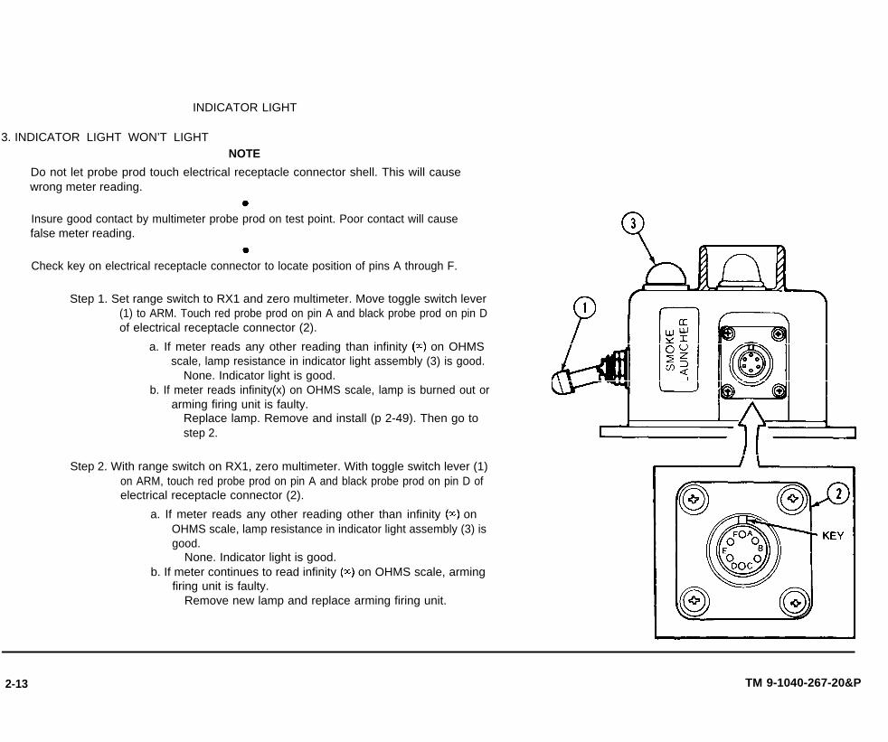
3. INDICATOR LIGHT WON’T LIGHTNOTE
Do not let probe prod touch electrical receptacle connector shell. This will cause wrong meter reading.
Insure good contact by multimeter probe prod on test point. Poor contact will causefalse meter reading.
Check key on electrical receptacle connector to locate position of pins A through F.
Step 1. Set range switch to RX1 and zero multimeter. Move toggle switch lever(1) to ARM. Touch red probe prod on pin A and black probe prod on pin Dof electrical receptacle connector (2).
a. If meter reads any other reading than infinity (z) on OHMSscale, lamp resistance in indicator light assembly (3) is good.
None. Indicator light is good.b. If meter reads infinity(x) on OHMS scale, lamp is burned out or
arming firing unit is faulty.Replace lamp. Remove and install (p 2-49). Then go tostep 2.
Step 2. With range switch on RX1, zero multimeter. With toggle switch lever (1)on ARM, touch red probe prod on pin A and black probe prod on pin D ofelectrical receptacle connector (2).
a. If meter reads any other reading other than infinity (z) onOHMS scale, lamp resistance in indicator light assembly (3) isgood.
None. Indicator light is good.b. If meter continues to read infinity (z) on OHMS scale, arming
firing unit is faulty.Remove new lamp and replace arming firing unit.
2-13 TM 9-1040-267-20&P
2-14
Section V. MAINTENANCE
2-7. INTRODUCTION. This manual covers all models of the launcher. If themaintenance task applies to all models, configurations will not be listed. Nospecial environmental conditions are listed because none are required.
TM 9-1040-267-20&P
PROCEDURES
2-8. DISCHARGER-MAINTENANCE INSTRUCTIONS.
This task covers:
a. Removalb. Cleaningc. Installation
d. Testinge. Inspectionf. Painting
INITIAL SETUP
Test EquipmentMultimeter TS-352B/U or equal
ToolsSC 5180-90-CL-N26
General Mechanic’s Automotive Tool Kit NSN 5180-00-177-7033
SC 5180-95-CL-A51Turret Mechanic’s Tool Kit NSN 5180-00-695-0139Paint Brush NSN 8020-00-297-6657
SC 5180-91-CL-R13Socket Wrench Set NSN 5120-00-542-5799Soldering Gun NSN 3439-00-004-0915
SC 4910-95-CL-A74Soldering Torch Kit NSN 3439-00-542-0531Tool Kit NSN 5180-00-876-9336Wire Brush NSN 7920-00-291-5815
Materials/PartsCleaning compound (RBC) (item 1, app D)Cloth (item 2, app D)Enamel (item 3, app D)
Gasket NSN 5330-00-641-4338Machine screw NSN 5305-00-006-9408Preformed packing NSN 5330-00-248-3840Preformed packing NSN 5330-00-252-6050Primer (item 5, app D)Primer coating (item 6, app D)Sealing compound (item 7 or 8, app D)Solder (item 9, app D)
ReferencesSC 4910-95-CL-A74SC 5180-91-CL-R13SC 5180-95-CL-A51TB SIG 222TM 11-6625-366-10TM 43-0139
Troubleshooting ReferencesTable 2-2, malfunction 1Discharger Won’t Fire.

LOCATION ITEM ACTION REMARKS
a. Electrical Contacts - Maintenance Instructions.
NOTEThis procedure is used to replace any of four electrical contacts. Replace only as needed to correctfaults.
REMOVAL
CAUTIONTo avoid damage to discharger, do not put strain on wires.
1 Discharger Base a. Screws (1) Remove eight screws.
b. Cover plate (2) and Remove from discharger base (4).gasket (3)
c. Electrical contact Remove self-locking nut (5) and disconnect termi-nal (6) from bushing (7).
2-15 TM 9-1040-267-20&P

2-16 TM 9-1040-267-20&P
2-8. DISCHARGER - MAINTENANCE INSTRUCTIONS (CONT).
LOCATION ITEM ACTION REMARKS
a. Electrical Contacts - Maintenance Instructions (Cont).
REMOVAL (Cont)
Tube
3 Discharger Base
Electrical
Electrical contact
Using socket wrenchsocket, hold bushing
handle with(7).
Remove large nut (8) and lock washer (9). Removebushing (7) from discharger tube (10). “Discarditems 5, 7, 8, and 9.

C L E A N I N G
Discharger Tube Tube base (1)
INSTALLATION
1 Electrical Contact a.
Clean withD) on paintapp D).
cleaning compoundbrush. Wipe dry with
Self-locking nut (1), Remove from new bushing (4).
(RBC) (item 1, appclean cloth (item 2,
large nut (2), and lockwasher (3)
CAUTIONFor a tight seal, do not twist preformed packing when inserting into groove of bushing.
b. Preformed packing (5) Insert into groove (6).
2 Discharger Tube Bushing (4) Push through hole in tube base.
2-17 TM 9-1040-267-20&P
2-18 TM 9-1040-267-20&P
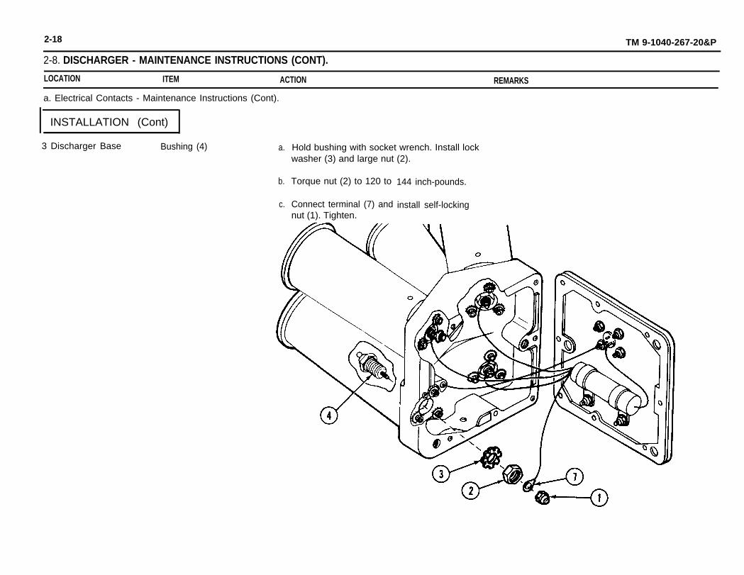
2-8. DISCHARGER - MAINTENANCE INSTRUCTIONS (CONT).
LOCATION ITEM ACTION REMARKS
a. Electrical Contacts - Maintenance Instructions (Cont).
INSTALLATION (Cont)
3 Discharger Base Bushing (4) a.
b.
c.
Hold bushing with socket wrench. Install lockwasher (3) and large nut (2).
Torque nut (2) to 120 to
Connect terminal (7) and
144 inch-pounds.
install self-lockingnut (1). Tighten.

TESTING
Discharger
INSPECTION
Discharger
2-19
Electrical contact Troubleshoot, using multimeter to do steps 2and 6 under malfunction 1 in table 2-2 (p 2-5).
Gasket (1) If brittle or torn, replace.
TM 9-1040-267-20&P

2-20 TM 9-1040-267-20&P
2-8. DISCHARGER - MAINTENANCE INSTRUCTIONS (CONT).
LOCATION ITEM ACTION REMARKS
a. Electrical Contacts - Maintenance Instructions (Cont).
INSTALLATION
To avoid damage
Discharger
discharger,CAUTION
do not pinch wires between cover plate and discharger
a.
b.
Gasket (1) and cover Install gasket and cover plate.plate (2)
Screws (3) a.
b.
Apply heavy coating of7 or 8, app D) to screw
Install eight screws and
base.

PAINTING
NOTEDo not paint electrical receptacle connector, electrical contacts, nameplate, or screws. Do not letpaint clog mounting holes or drain holes.
Discharger All outside surfaces a.
b.
b. Resistor - Maintenance Instructions.
Remove burrs, corrosion, and chipped paint.
Touch up with primer (item 6, app D) and See TM 43-0139.enamel (item 3, app D).
REMOVAL
CAUTIONTo avoid damage to discharger, do not put strain on wires.
1 Discharger Base a. Screws (1) Remove eight screws.
2-21 TM 9-1040-267-20&P

2-22 TM 9-1040-267-20&P
2-8. DISCHARGER - MAINTENANCE INSTRUCTIONS (CONT).
LOCATION ITEM ACTION REMARKS
b. Resistor - Maintenance Instructions (Cont).
REMOVAL (Cont)
1 Discharger b.
Base (Cont).c.
d.
e.
Cover plate (2) andgasket (3)
Electrical contact (5)
Ground screw (8) andlock washer (9)
Ground terminal (10).
Remove from discharger base (4).
Remove four self-locking nuts (6) and disconnectfour resistor wire terminals (7).
Remove ground screw and lock washer.
Disconnect ground terminal.

2 Cover Plate a.
b.
Electrical receptacle a. Remove pin A.connector (11 )
b. Remove insulation sleeving and unsolderresistor wire lead from pin A.
Resistor (12) Remove two self-locking nuts (13), washers (14),and resistor (12) with clamps (15).
2-23 TM 9-1040-267-20&P

2-24 TM 9-1040-267-20&P
2-8. DISCHARGER - MAINTENANCE INSTRUCTIONS (CONT).
LOCATION ITEM ACTION REMARKS
b. Resistor - Maintenance Instructions (Cont).
T E S T I N G
1 Multimeter
2 Resistor
Range switch and meter Set range switch on RX1 and zero multimeter.
New resistor (1) Touch black probe on single wire lead and placered probe on terminal for each of four wires, one ata time.
3 Multimeter Meter a. If meter reads from 13 to 18 on OHMS scale,resistance is good.
b. If any one of four readings is below 13 or above18 on OHMS scale, replace resistor.

INSTALLATION
1 Cover Plate a. Resistor (1)
Do not break strands
Install on studs with two washers (2) and two self-Iocking nuts (3). Tighten.
CAUTIONon wire when stripping insulation.
b. Electrical receptacle a.connector (4)
b.
c.
d.
e.
f.
Strip wire insulation on single resistor wire todepth of solder well.
Cut a piece of insulation sleeving 3/4 incheslong.
Slide new insulation sleeving on wire.
Insert wire lead into pin A and solder (item 9,app D). See TB SIG 222.
Slide insulation sleeving over soldered connec-tion and heatshrink.
Insert pin A into electrical receptacleconnector (4).
2-25 TM 9-1040-267-20&P

2-26 TM 9-1040-267-20&P
2-8. DISCHARGER - MAINTENANCE INSTRUCTIONS (CONT).
LOCATION ITEM ACTION REMARKS
b. Resistor - Maintenance Instructions (Cont).
INSTALLATION (Cont)
2 Discharger Base a. Electrical
b. Ground wire
Connect four terminals (5) and installlocking nuts (6). Tighten.
Connect terminal (7) to base with lock
four self-
washer (8)

TESTING
Discharger
INSPECTION
Discharger
Electrical circuits
Gasket (1)
Troubleshoot, using multimeter to do steps 2and 5 under malfunction 1 in table 2-2 (p 2-5).
If brittle or torn, replace.
2-27 TM 9-1040-267-20&P

2-28 TM 9-1040-267-20&P
2-8. DISCHARGER - MAINTENANCE INSTRUCTIONS (CONT).
LOCATION ITEM ACTION REMARKS
b. Resistor - Maintenance Instructions (Cont).
INSTALLATION
To avoid damage
Discharger base
CAUTIONto discharger, do not pinch wires between cover plate and discharger base.
a. Gasket (1) and cover Install gasket and cover plate.plate (2)
b. Screws (3) a. Apply heavy coating of sealing compound (item7 or 8, app D) to screw threads.
b. Install eight screws and tighten.
NOTEDo not paint electrical receptacle connector, electrical contacts, nameplate, or screws. Do not let
P A I N T I N G
paint clog mounting holes or drain holes.
Discharger All outside surfaces a.
b.
Remove burrs, corrosion, and chipped paint.
Touch up with primer (item 6, app D) andenamel (item 3, app D).
See TM 43-0139.

C. Electrical Receptacle Connector - Maintenance Instructions.
R E M O V A L
CAUTIONTo avoid damage to discharger, do not put strain on wires.
Make sure electrical receptacle connector key location is marked on cover plate so it can beinstalled in the same place. If not done, wires can be damaged.
1 Discharger Base a. Cover plate (1) Mark electrical receptacle connector (2) keylocation.
b. Screws (3) Remove eight screws.
c. Cover plate (1) and Remove from discharger base (5).gasket (4)
2-29 TM 9-1040-267-20&P
2-30 TM 9-1040-267-20&P
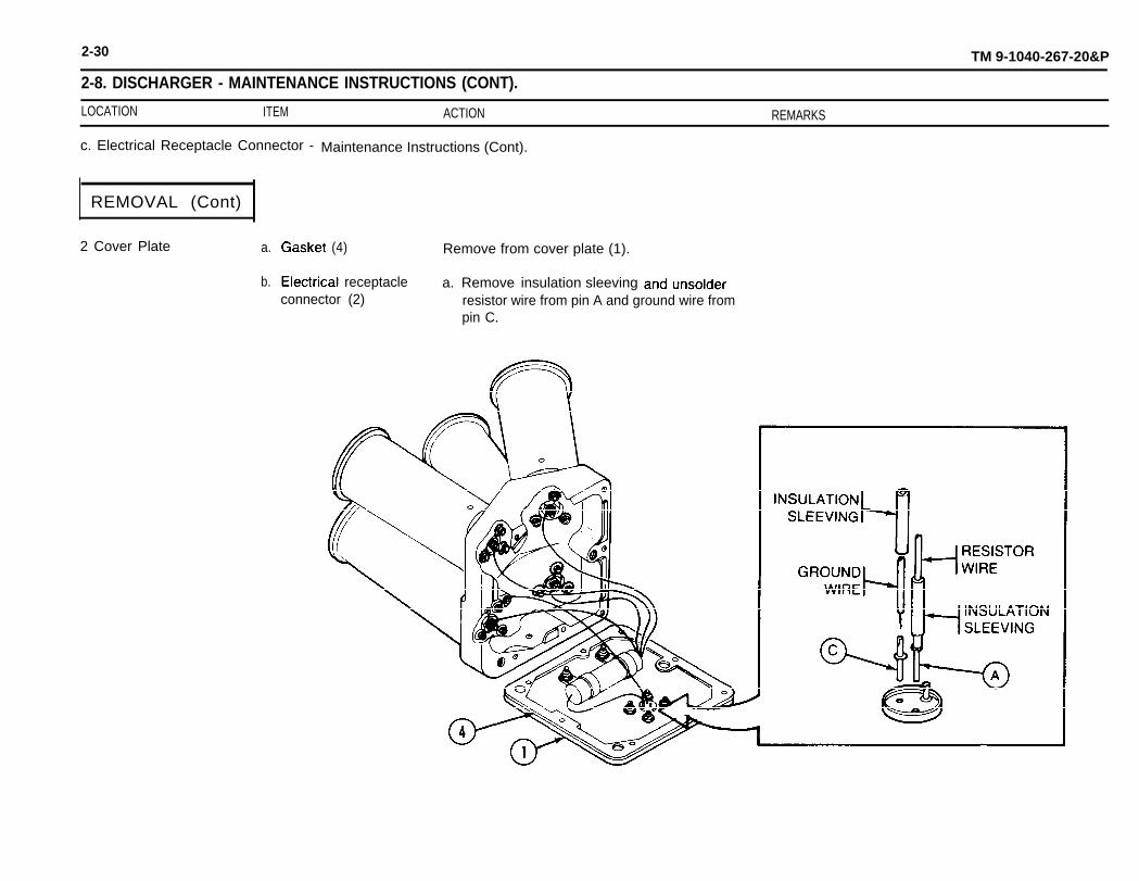
2-8. DISCHARGER - MAINTENANCE INSTRUCTIONS (CONT).
LOCATION ITEM ACTION REMARKS
c. Electrical Receptacle Connector - Maintenance Instructions (Cont).
REMOVAL (Cont)
2 Cover Plate a.
b.
(4) Remove from cover plate (1).
receptacle a. Removeconnector (2) resistor wire from pin A and ground wire from
pin C.
insulation sleeving

INSTALLATION
Cover Plate Electrical receptacle a.connector (1)
b.
c.
d.
Insert four screws (2) in electrical receptacleconnector.
Place gasket (3) on electrical receptacle con-nector (1).
Aline key with location mark on outside of coverplate (4).
Install on cover plate (4) with four washers (5)and four self-locking nuts (6). Tighten.
2-31

2-32 TM 9-1040-267-20&P
2-8. DISCHARGER - MAINTENANCE INSTRUCTIONS (CONT).
LOCATION ITEM ACTION REMARKS
c. Electrical Receptacle Connector - Maintenance Instructions
INSTALLATION (Cont)
Cover Plate (Cont). Electrical receptacle e.connector (1) (Cont).
f.
g.
h.
(Cont).
Cut two pieces of insulation sleeving 3/4 incheslong.
Slide insulation sleeving on wires.
Remove pins A and C.
Solder (item 9, app D) one pin to resistor wireand one pin to ground wire. See TB SIG 222.
CAUTIONBe sure that pins are inserted into correct holes of electrical receptacle connector or discharger willnot fire.
i. Insert resistor wire pin into hole A.
j. Insert ground wire pin into hole C.
k. Slide insulation sleeving over soldered connec-tions and heatshrink.

TESTING
Discharger Electrical circuits Troubleshoot, using multimeter to do steps 2,3,and 5 under malfunction 1 in table 2-2 (p 2-5).
INSPECTION
Gasket Gasket material (1) If brittle or torn, replace.
INSTALLATION
1 Cover Plate Gasket (1) Install on
TM 9-1040-267-20&P2-33

2-34 TM 9-1040-267-20&P
2-8. DISCHARGER - MAINTENANCE INSTRUCTIONS (CONT).
LOCATION ITEM ACTION REMARKS
c. Electrical Receptacle Connector - Maintenance Instructions (Cont).
INSTALLATION (Cont)
To avoid damage to discharger, do
2 Discharger Base a. Gasket (1)plate (2)
b. Screws (3)
CAUTIONnot pinch wires between cover plate and discharger base.
and cover Install gasket and cover plate.
a. Apply heavy coating of sealing compound (item7 or 8, app D) to screw threads.
b. Install eight screws and tighten.
P A I N T I N G
NOTEDo not paint electrical receptacle connector, electrical contacts, nameplate, or screws. Do not letpaint clog mounting holes or drain holes.
Discharger All outside surfaces a. Remove burrs, corrosion, and chipped paint.
b. Touch up with primer (item 6, app D) and See TM 43-0139.enamel (item 3, App D).

d. Discharger Tubes - Maintenance Instructions.
NOTE
This procedure is used to replace any one of four discharger tubes. Replace only as needed tocorrect faults.
REMOVAL
To
1 Discharger Base
avoid damage
a. Screws (1)
toCAUTION
discharger do not put strain on wires.
Remove eight screw
TM 9-1040-267-20&P2-35

2-36 TM 9-1040-267-20&P
2-8. DISCHARGER - MAINTENANCE INSTRUCTIONS (CONT).
LOCATION ITEM ACTION REMARKS
d. Discharger Tubes - Maintenance Instructions (Cont)
REMOVAL (Cont)
1 Discharger b. Cover plateBase (Cont). gasket (3)
2 Discharger Tube
3 Discharger Base
(2) and Remove from discharger base (4).
C. Electrical contact
Electrical contact
a. Electrical contact
Remove self-locking nut (5) and disconnectterminal (6).
Using socket wrench handle with extension andsocket, hold bushing (7).
bushing (7) from dischargerRemove large nut (8) and lock washer (9). Remove
tube (10).

b. Screws (11), lock Remove three screws, three lock washers, and
washers, and dis- discharger tube.charger tube (10)
TM 9-1040-267-20&P2-37

2-38 TM 9-1040-267-20&P
2-8. DISCHARGER - MAINTENANCE INSTRUCTIONS (CONT).
LOCATION ITEM ACTION REMARKS
d. Discharger Tubes - Maintenance Instructions (Cont).
R E M O V A L ( C o n t )
3 Discharger c. Preformed packingBase (Cont).
(13) Remove from groove in discharger base (4) anddiscard.
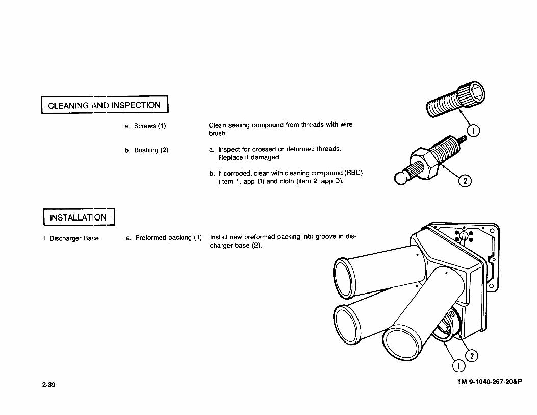
TM
9-1040-267-20&P
2-39

2-40 TM 9-1040-267-20&P
2-8. DISCHARGER - MAINTENANCE INSTRUCTIONS (CONT).
LOCATION ITEM ACTION REMARKS
d. Discharger Tubes - Maintenance Instructions (Cont).
INSTALLATION (Cont)
1. Dischager b. Screw (3) and dis- Coat threads of screw and threads in dischargerBase (Cont). charger tube (4) tube with adhesive primer (item 5, app D) and
sealing compound (item 7 or 8, app D).
2 Bushing Preformed packing (6) a. Remove from groove in bushing (7).
CAUTIONFor a tight seal, do not twist preformed packing when inserting into groove.
b. Insert new preformed packing into groove inbushing (7).

3 Discharger Tube Bushing (7) Push through hole in tube base.
4 Discharger Base Electrical contact a. Hold bushing (7) with socket wrench. Install lockwasher (8) and large nut (9).
b. Torque large nut (9) to 120 to 144 inch-pounds.
c. Connect terminal (10) and install self-lockingnut (11 ). Tighten.
2-41 TM 9-1040-267-20&P

2-42 TM 9-1040-267-20&P
2-8. DISCHARGER - MAINTENANCE INSTRUCTIONS (CONT).
LOCATION ITEM ACTION REMARKS
d. Discharger Tubes - Maintenance Instructions (Cont).
TESTING
Discharger Electrical contact Troubleshoot, using multimeter to do steps 2and 6 under malfunction 1 in table 2-2 (p 2-5)
INSPECTION
Discharger Gasket (1) If brittle or torn, replace.

plate (2)
b. Screws (3) a.
b.
INSTALLATION
CAUTIONTo avoid damage to discharger, do not pinch wires between cover plate and discharger base.
Discharger Base a. Gasket (1) and cover Install gasket and cover plate.
Apply heavy coating of sealing compound (item7 or 8, app D) to screw threads.
Install eight screws and tighten.
PAINTING
NOTEDo not paint electrical receptacle connector, electrical contacts, nameplate, or screws. Do not letpaint clog mounting holes or drain holes.
Discharger All outside surfaces a.
b.
Remove burrs, corrosion, and chipped paint.
Touch up with primer (item 6, app D) and See TM 43-0139.enamel (item 3, app D).
2-43 TM 9-1040-267-20&P
8 DIS
CH
AR
GE
R - M
AIN
TE
NA
NC
E IN
ST
RU
CT
ION
S (C
ON
T).
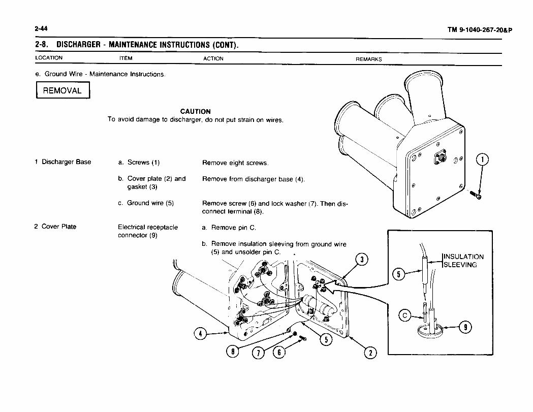
2-44

lNSTALLATION
Do not break strands
Ground wire (1)
CAUTIONon wire when stripping insulation.
a. Cut new wire about 8 inches long.
b.
c.
d.
e.
f.
g.
h.
Strip insulation to length of terminal sleeve. in-sert wire into terminal. Crimp terminal and sol-der (item 9, app D). See TB SIG 222.
Cut two pieces of insulation sleeving 3/4 incheslong and slide to center of wire.
Slide one insulation sleeving over terminalsleeve and heatshrink.
Strip insulation to depth of solder well of pin C.Insert ground wire into solder well and solder(item 9, app D) to pin C. See TB SIG 222.
Slide insulation sleeving over soldered connec-tion and heatshrink.
Insert pin C into electrical receptacle connector (2)
Use screw (3) and lock washer (4) to connectterminal (5) to discharger base (6) and tighten.
2-45 TM 9-1040-267-20&P
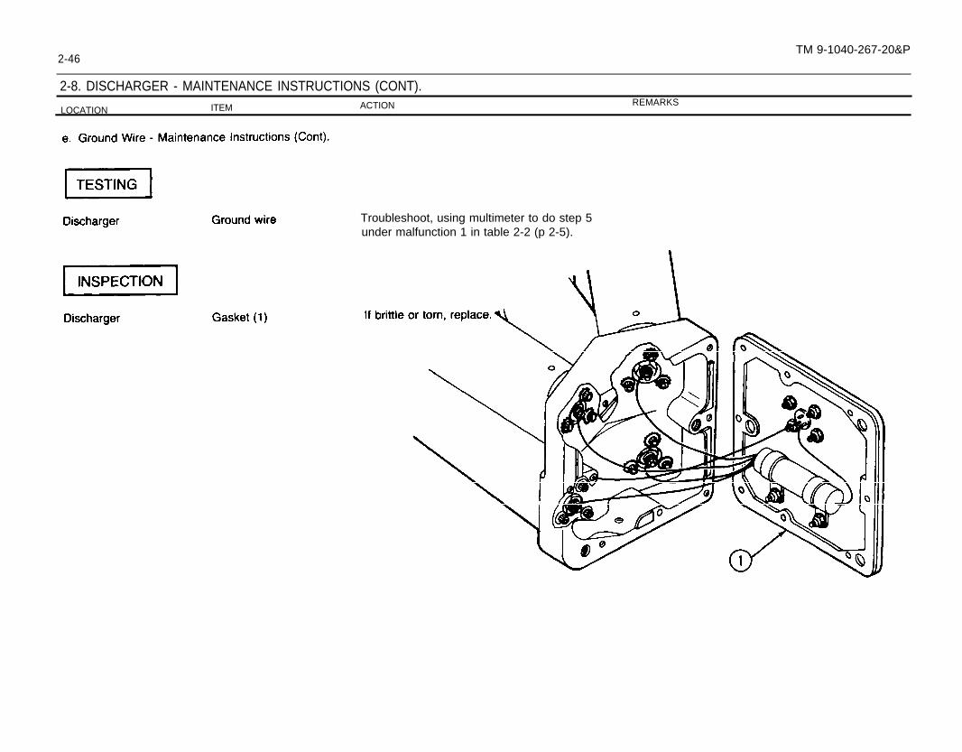
2-46TM 9-1040-267-20&P
2-8. DISCHARGER - MAINTENANCE INSTRUCTIONS (CONT).
LOCATION ITEM ACTION REMARKS
Troubleshoot, using multimeter to do step 5under malfunction 1 in table 2-2 (p 2-5).

To avoid damage to discharger, do
Discharger Base a. Gasket (1)plate (2)
b. Screws (3)
CAUTIONnot pinch wires between cover plate and discharger base.
and cover Install gasket and cover plate.
. . a. Apply heavy coating of sealing compound (item7 or 8, app D) to screw threads.
b. Install eight screws and tighten.
NOTEDo not paint electrical receptacle connector, electricalpaint clog mounting holes or drain holes.
Discharger All outside surfaces a.
b.
contacts, nameplate, or screws. Do not let
Remove burrs, corrosion, and chipped paint.
Touch up with primer (item 6, app D) and See TM 43-0139.enamel (item 3, app D).
2-47 TM 9-1040-267-20&P

2-48 TM 9-1040-267-20&P
2-9. ARMING FIRING UNIT - MAINTENANCE INSTRUCTIONS.
This task covers:
a. Cleaning and Inspectionb. Testing
c. Repair
Applicable ConfigurationM243 launcher NSN 1040-01-059-0560M259 launcher NSN 1040-01-107-7501
Test EquipmentMultimeter TS-352B/U or equal
ToolsSC 5180-90-CL-N26
General Mechanic’s Automotive Tool Kit NSN 5180-00-177-7033SC 5180-95-CL-A51
Turret Mechanic’s Tool Kit NSN 5180-00-695-0139
MaterialslPartsCloth (item 2, app D)
ReferencesSC 5180-95-CL-A51TM 11-6625-366-10
Troubleshooting ReferencesTable 2-2, malfunction 2 Arming Firing Unit Won’t Fire DischargersTable 2-2, malfunction 3 Indicator Light Won’t Light
LOCATION ITEM ACTION REMARKS
Arming Firing Unit Exterior All parts Clean and inspect (para 2-3).
Arming Firing Unit Electrical receptacleconnector
Troubleshoot, using multimeter to do testsunder malfunctions 2 and 3 in table 2-2(p 2-5).

Arming Firing Unit
Arming Firing Unit
d. Lens (1)
b. Socket (4)
c. Lens (1)
Unscrew and remove lens with preformed packing(2) and lamp (3).
If corroded, clean socket.
a.
b.
c.
d.
e.
Check preformed packing (2). If cut, torn, ormissing, replace lens which includes preformedpacking.
Pry lamp (3) from Iens and replace ifburned out.
Replace lens if cracked or if chipped.
Instal l new lamp (3) in lens.
Screw lens with preformed packing (2) andlamp (3) into socket (4).
Indicator light assembly Troubleshoot, using multimeter to do steps 1and 2 under malfunction 3 in table 2-2(p 2-5).
2-49TM 9-1040-267-20&P

2-50 TM 9-1040-267-20&P
2-10. GRENADE STORAGE BOX - MAINTENANCE INSTRUCTIONS.
This task covers:
a. Cleaning d.
b. Inspection e.
c. Removal
InstallationPainting
Applicable ConfigurationM243 launcher NSN 1040-01-059-0560
ToolsSC 4910-95-CL-A74
Hammer NSN 5120-00-900-6103Marking Stencil Set NSN 7520-00-298-7043Wire Brush NSN 7920-00-291-5815
SC 5180-95-CL-A51Turret Mechanic’s Tool Kit NSN 5180-00-695-0139Paint Brush NSN 8020-00-297-6657
MaterialslPartsCloth (item 2, app D)Enamel (item 3, app D)Pressure sensitive adhesive tape (item 10, app D)Primer coating (item 6, app D)Stencil marking ink (item 4, app D)
ReferencesSC 4910-95-CL-A74SC5180-95-CL-A51TM 43-0139

Wipe off dirt and grim
e with dam
p cloth (item 2, app D
).
2-51 Change 1

2-52 Change 1 TM 9-1040-267-20&P
2-10. GRENADE STORAGE BOX - MAINTENANCE INSTRUCTIONS (CONT).
LOCATION ITEM ACTION REMARKS
Grenade Stowage Box a. Clamping catches (1)
b. Strike (4)
a.
b.
c.
a.
b.
c.
d.
Cut off head of rivets (2) flush from insidebox (3) with chisel.
Separate clamping catch (1) from box (3) withchisel.
Pry clamping catch (1) and rivets (2) from box(3) with pry bar.
Carefully peel back pad (6) inside lid toexpose rivets (5).
Cut off rivets (5) flush from inside box (3)with chisel.
Separate strike (4) from lid with chisel.
Pry strike (4) and rivets (5) from lid withpry bar.

Grenade Stowage BOX a. Clamping catches (1) a. Push rivets (2) through holes from inside ofbox (3).
b. Strike (4)
b. Place clamping catch (1) on rivets (2).
c. Place heavy hammer behind head of rivet (2).
d. Peen end of rivet (2) with another hammer.
a. Push rivets (5) through holes from inside box (3).
b. Place strike (4) on rivets (5).
Grenade Stowage Box a. All outside surfaces a.
b.
c. Place heavy hammer
d. Peen end of rivet (5)
e. Replace pad (6).
b. Lid (1)
behind head of rivet (5).
with another hammer.
Remove burrs, chipped paint, and rust.
Paint with primer (item 6, app D) and enamel(item 3, app D) as needed. See TM 43-0139.
Stencil marking “Smoke Grenades” (2) in 1 inchhigh letters with stencil marking ink (item 4, app D).Mask unpainted surfaces with tape (item 10,app D).
2-53 Change 1 TM 9-1040-267-20&P
2-54 TM 91040-267-20&P
SECTION VI. PREPARATION FOR STORAGE OR SHIPMENT
2-11. SECURITY PROCEDURES. The launchers are non-sensitive itemsand may be stored or shipped, using standard storage and transportationhandling procedures.
2-12. PRESERVATION, PACKAGING, PACKING, MARKING, ANDSHIPPING REQUIREMENTS. Prior to being installed on the armoredvehicles, the launchers will be stored in their original shipping containers,using the same preservation and packing materials described in Section II.Service Upon Receipt.
2-13. PRESERVATION MATERIALS. No special preservation materialsare required for storage or shipment of the launcher.
2-14. TYPE OF STORAGE. Usually, the launchers will require only shortterm storage of 1 to 45 days before being installed on the armored vehicles.This equipment will be placed in administrative storage (TM 740-90-1) where itcan be readied for mission performance within 24 hours. The administrativestorage site should protect the launchers from the elements and allow accessfor visual inspection. No special storage facilities are needed.

APPENDIX AREFERENCES
A-1. TECHNICAL MANUALS.
TM 740-90-1 . . . . . . . . . . . . . . . . . Administrative Storage of Equipment
TM 43-0002-31 . . . . . . . . . . . . . . Destruction of Chemical Weapons and Defense Equipment to Prevent Enemy Use
TM 11-6625-366-10 . . . . . . . . . . Operator’s Manual for Multimeter TS-352 B/U (NSN 6625-00-552-0142)
TM 43-0139 . . . . . . . . . . . . . . . . . Painting Instructions for Field Use
A-2. TECHNICAL BULLETINS.
TBSIG 222 . . . . . . . . . . . . . . . . . . Solder and Soldering
A-3. PAMPHLETS.
DA PAM310-1 . . . . . . . . . . . . . . . Consolidated Index of Army Publications and Blank Forms
DA PAM 738-750 . . . . . . . . . The Army Maintenance Management System (TAMMS)
A-4. FIELD MANUALS.
FM21-11 (TEST) . . . . . . . . . . . . . First Aid for Soldiers
A-1 Change 1 TM 9-1040-267-20&P

A-2 TM 9-1040-267-20&P
A-5. SUPPLY CATALOGS.
SC4910-95-CL-A74 . . . . . . . . . Shop Equipment, Automotive Maintenance and Repair: OrganizationalMaintenance, Common No. 1, Less Power (NSN 4910-00-754-0654) (LINW32593) and MAP only (NSN 4910-00-919-0098)
SC 5180-91-CL-R13 . . . . . . . . . Tool Kit, Electronic Equipment, TK-101/G(NSN5180-00-064-51 78) (LIN W 37483)SC 5180-95-CL-A51 . . . . . . . . . Tool Kit, Turret Mechanics: (5180-00-695-01 39) (W57801)SC 5180-90-CL-N26 . . . . . . . . . Tool Kit, General Mechanic’s Automotive (NSN 5180-00-177-7033)
(LIN W33004)A-6. SUPPLY BULLETINS.
SB 708-42 . . . . . . . . . . . . . . . . . . . Federal Supply Code for Manufacturers’; United States and Canada-Code to Name.(Cataloging Handbook H4-2) (GSA-FSS-H4-2)
A-7. COMMON TABLE of ALLOWANCES.
CTA 50-970 . . . . . . . . . . . . . . . . . Expendable Items: (Except: Medical Class V, Repair Parts and Heraldic Items)
A-8. BLANK FORMS.
DA Form 2028 . . . . . . . . . . . . . . . . Recommended Changes to Publications and Blank Forms
DA Form 2028 -2 . . . . . . . . . . . . . Recommended Changes to Equipment Technical Publications
SF 364 . . . . . . . . . . . . . . . . . . . . . . Report of Discrepancy (ROD)
SF 368 . . . . . . . . . . . . . . . . . . . . . . Quality Deficiency Report (Category 11)

APPENDIX BMAINTENANCE ALLOCATION CHART
Section I. INTRODUCTION
B1. GENERAL.a. This section provides a general explanation of all maintenance and repair
functions authorized at various maintenance categories.b. The Maintenance Allocation Chart (MAC) in section II designates overall
authority and responsibility for the performance of maintenance functions on theidentified end item or component. The application of the maintenance functionsto the end item or component will be consistent with the capacities andcapabilities of the designated maintenance categories.
c. Section Ill lists the tools and test equipment (both special tools andcommon tool sets) required for each maintenance function as referenced fromsection Il.
d. Section IV contains supplemental instructions and explanatory notes fora particular maintenance function.
B-2. MAINTENANCE FUNCTIONS. Maintenance functions will be limited toand defined as follows: (except for ammunition MAC’).
a. inspect. To determine the serviceability of an item by comparing itsphysical, mechanical, and/or electrical characteristics with established stand-ards through examination (e.g., by sight, sound, or feel).
b. Test. To verify serviceability by measuring the mechanical, pneumatic,hydraulic, or electrical characteristics of an item and comparing those charac-teristics with prescribed standards.
c. Service. Operations required periodically to keep an item in properoperating condition, i.e., to clean (includes decontaminate, when required), topreserve, to drain, to paint, or to replenish fuel, lubricants, chemical fluids, orgases.
d. Adjust. To maintain or regulate, within prescribed limits, by bringing intoproper or exact position, or by setting the operating characteristics to specifiedparameters.
e. Aline. To adjust specified variable elements of an item to bring aboutoptimum or desired performance.
f. Calibrate. To determine and cause corrections to be made or to beadjusted on instruments or test, measuring and diagnostic equipments used inprecision measurements. Consists of comparisons of two instruments, one ofwhich is a certified standard of known accuracy, to detect and adjust anydiscrepancy in the accuracy of the instrument being compared.
g. Remove/Install. To remove and install the same item when required toperform service or other maintenance functions. Install may be the act ofemplacing, seating, or fixing into position a spare, repair part, or module (com-ponent or assembly) in a manner to allow the proper functioning of an equipmentor system.
h. Replace. To remove an unserviceable item and install a serviceablecounterpart in its place. “Replace” is authorized by the MAC and is shown as the3d position code of the SMR code.
i. Repair. The application of maintenance services2, including faultlocation/troubleshooting 3; removal/installation, and disassembly/assembly4
procedures and maintenance actionss to identify troubles and restore servicea-bility to an item by correcting specific damage, fault, malfunction, or failure in apart, subassembly, module (component of assembly), end item, or system.
1Exception is authorized for ammunition MAC to permit the redesignation/redefinition of maintenance function headings to more adequately identify
ammunition maintenance functions. The heading designations and definitions will be included in the appropriate technical manual for each category ofammunition.
2Services - inspect, test, service, adjust, aline, calibrate, and/or replace.3Fault locate/troubleshoot - The process of investigating and detecting the cause of equipment malfunctioning; the act of isolating a fault within a
system or unit under test (UUT).4Disassemble/assemble - encompasses the Step-by-step taking apart (or breakdown) of a spare/functional group coded Item to the level of lts least
componency identified as maintenance significant (i.e., assigned as SMR code) for the category of maintenance under consideration.5 Actions - welding, grinding, riveting, straightening, facing, remachinery, and/or resurfacing.
B-1 TM 9-1040-267-20&P

B-2
j. Overhaul. That maintenance effort (service/action) prescribed to restorean item to a completely serviceable/operational condition as required bymaintenance standards in appropriate technical publications (i.e., DMWR).Overhaul is normally the highest degree of maintenance performed by theArmy. Overhaul does not normally return an item to like new condition.
k. Rebuild. Consists of those services/actions necessary for the restora-tion of unserviceable equipment to a like new condition in accordance withoriginal manufacturing standards. Rebuild is the highest degree of materielmaintenance applied to Army equipment. The rebuild operation includes the actof returning to zero those age measurements (hours/miles, etc.) considered inclassifying Army equipment/components.
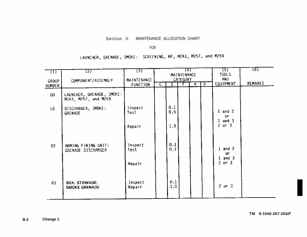
B-3. EXPLANATION OF COLUMNS IN THE MAC, SECTION II.a. Column 1, Group Number. Column 1 lists functional group code num-
bers, the purpose of which is to identify maintenance significant components,assemblies, subassemblies, and modules with the next higher assembly. Enditem group number shall be “00.”
b. Column 2, Component/Assemb/y. Column 2 contains the names ofcomponents, assemblies, subassemblies, and modules for which maintenanceis authorized.
c. Column 3, Maintenance Function. Column 3 lists the functions to beperformed on the item listed in Column 2. (For detailed explanation of thesefunctions, see paragraph B-2.)
d. Column 4, Maintenance Category. Column 4 specifies, by the listing of awork time figure in the appropriate subcolumn(s), the category of maintenanceauthorized to perform the function listed in column 3. This figure represents theactive time required to perform that maintenance function at the indicatedcategory of maintenance. If the number or complexity of the tasks within thelisted maintenance function vary at different maintenance categories, appro-priate work time figures will be shown for each category. The work time figurerepresents the average time required to restore an item (assembly, subassem-bly, component, module, end item, or system) to a serviceable condition undertypical field operating conditions. This time includes preparation time (includingany necessary disassembly/assembly time), troubleshooting/fault location
TM 9-1040-267-20&P
time, and quality assurance/quality control time in addition to the time requiredto perform the specific tasks identified for the maintenance functions authorizedin the maintenance allocation chart. The symbol designations for the variousmaintenance categories are as follows:
C . . . . . . . . . . . . . . . . . . . . . . . . . . . . . . . . . . . . . . . . . . . . . . . . Operator or CrewO . . . . . . . . . . . . . . . . . . . . . . . . . . . . . . . . . . . . . . . . . . . . . . Organizational MaintenanceF . . . . . . . . . . . . . . . . . . . . . . . . . . . . . . . . . . . . . Direct Support MaintenanceH . . . . . . . . . . . . . . . . . . . . . . . . . . . . . . . . . . . General Support MaintenanceL . . . . . . . . . . . . . . . . . . . . . . . . . . . . . . . Specialized Repair Activity (SRA6)D . . . . . . . . . . . . . . . . . . . . . . . . . . . . . . . . . . . . . . . . . . . . Depot Maintenance
e. Column 5, Took and Equipment. Column 5 specifies, by code, thosecommon tool sets (not individual tools) and special tools, TMDE, and supportequipment required to perform the designated function.
f. Column 6, Remarks. This column shall, when applicable, contain a lettercode, in alphabetic order, which shall be keyed to the remarks contained insection IV.
B-4. EXPLANATION OF COLUMNS IN TOOL AND TEST EQUIPMENTREQUIREMENTS, SECTION Ill.
a. Column 7, Reference Code. The tool and test equipment referencecode correlates with a code used in the MAC, section II, Column 5.
b. Column 2, Maintenance Category. The lowest category of maintenanceauthorized to use the tool or test equipment.
c. Column 3, Nomenclature. Name or identification of the tool or testequipment.
d. Column 4, National Stock Number. The National stock number of thetool or test equipment.
e. Column 5, Tool Number. The manufacturer’s part number.
B-5. EXPLANATION OF COLUMNS IN REMARKS, SECTION IV.a. Column 7, Reference Code. The code recorded in column 6, Section Il.b. Column 2, Remarks. This column lists information pertinent to the
maintenance function being performed as indicated in the MAC, section Il.
This maintenance category IS not included m Section 11, column (4) of the Maintenance Allocation Chart. To Identtfy funchons to this category ofmaintenance, enter a work time figure In the “H” column of SectIon II, column (4), and use an associated reference code in the Remarks column (6). Key thecode to SectIon IV, Remarks, and explain the SRA complete repair application there. The explanatory remark(s) shall reference the specific Repair Parts andSpecial Tools List (RPSTL) TM whtch contains additional SRA crkerla and the authorized spare/repair parts.
Section II. MAINTENANCE ALLOCATION CHART
FOR
TM 9-1040-267-20&P
B-3 Change 1


APPENDIX CORGANIZATIONAL MAINTENANCE REPAIR PARTS
AND SPECIAL TOOLS LIST
Section I. INTRODUCTION
C-1. SCOPE. This appendix lists and authorizes spares and repair parts; special tools; special test, measurement, anddiagnostic equipment (TMDE); and other special support equipment required for performance of organizational, maintenanceof the grenade launchers. It authorizes the requisitioning, issue, and disposition of spares, repair parts and special tools asindicated by the Source, Maintenance and Recoverability (SMR) codes.
C-2. GENERAL. This Repair Parts and Special Tools List is divided into the following sections:a. Section II. Repair Parts List. A list of spares and repair parts authorized by this RPSTL for use in the performance of
maintenance. The list also includes parts which must be removed for replacement of the authorized parts. Parts lists arecomposed of functional groups in ascending alphanumeric sequence, with the parts in each group listed in ascending figureand item number sequence. Bulk materials are listed in NSN sequence.
b. Section ///. Special Tools List. A list of special tools, special TMDE, and other special support equipment authorized bythis RPSTL for the performance of maintenance.
c. Section IV. National Stock Number and Part Number Index. A list, in National item identification number (NIIN)sequence, of all National stock numbers (NSN) appearing in the listings, followed by a list in alphanumeric sequence of all partnumbers appearing in the listings. National stock numbers and part numbers are cross-referenced to each illustration figureand item number appearance.
C-3. EXPLANATION OF COLUMNS.a. ILLUSTRATION (Column (1)). This column is divided as follows:
(1) ((a) FIG NO.) Figure Number. Indicates the figure number illustrating an exploded view of a functional group.(2) ((b) ITEM NO.). Indicates the number used to identify items called out in the illustration.
C-1 TM 9-1040-267-20&P

C - 2 TM 9-1040-267-20&Pb. SMR CODE (Column (2)). The Source, Maintenance, and Recoverability (SMR) code is a 5-position code containing
supply/requisitioning information, maintenance category authorization criteria, and disposition instructions, as shown in thefollowing breakout:
Complete Repair: Maintenance capacity, capability, and authority to perform all the corrective maintenance tasks of the“Repair” function in a use/user environment in order to restore serviceability to a failed item.
(1) Source Code. The source code tells you how you get an item needed for maintenance, repair, or overhaul of an enditem/equipment. Source codes are always the first two positions of the SMR code, Explanations of source codes follow:
Code Explanation
Stocked items; use the applicable NSN to request/requisition items with these source codes. Theyare authorized to the category indicated by the code entered in the 3d position of the SMR code.
--------------------------------------------------------------------------------------------------------------------------Items with these codes are not to be requested/requisitioned individually. They are part of a kitwhich is authorized to the maintenance category indicated in the 3d position of the SMR code. Thecomplete kit must be requisitioned and applied.------------------------------------------------------------------------------------------------------------------------

Code
C-3
Explanation
Items with these codes are not to be requested/requisitioned individually. They must be made frombulk material which is identified by NSN in the Description column and listed in the Bulk Materialgroup in the repair parts list in this appendix. If the item is authorized to you by the 3d position codeof the SMR code, but the source code indicates it is made at a higher category, order the item fromthe higher category of maintenance.
Items with these codes are not to be requested/requisitioned individually. The parts that makeupthe assembled item must be requisitioned or fabricated and assembled at the category ofmaintenance indicated by the source code. If the 3d position code of the SMR code authorizes youto replace the item, but the source code indicates the item is assembled at a higher category, orderthe item from the higher category of maintenance.
Do not requisition an “XA’’-coded item. Order its next higher assembly. (Also, refer to the NOTE below.)
If an “X6” item is not available from salvage, order it using the FSCM and part number given.
Installation drawing diagram instruction sheet field service drawing, that is identified by manufacturer’s part number.
Item is not stocked. Order an “XD’’-coded item through normal supply channels using the FSCM and part numbergiven, if no NSN is available.
NOTE
Cannibalization or controlled exchange, when authorized, maybe used as a source of supply for items with theabove source codes, except for those source coded “XA” or those aircraft support items restricted by require-ments of AR 700-42.
(2) Maintenance Code. Maintenance codes tell you the category(s) of maintenance authorized to USE and REPAIRsupport items. The maintenance codes are entered in the third and fourth positions of the SMR Code as follows:
(a) The maintenance code entered in the third position tells you the lowest maintenance category authorized toremove, replace, and use an item. The maintenance code entered in the third position will indicate authorization to one of thefollowing categories of maintenance.
TM 9-1040-267-20&P

C-4 TM 9-1040-267-20&PCode Application/Explanation
C - Crew or operator maintenance done within organizational or aviation unit maintenance.
O - Organizational or aviation unit category can remove, replace, and use the item.
F - Direct support or aviation intermediate category can remove, replace, and use the item.
H - General support category can remove, replace, and use the item.
L - Specialized repair activity can remove, replace, and use the item.
D - Depot category can remove, replace, and use the item.
(b) The maintenance code entered in the fourth position tells you whether or not the item is to be repaired and identifies thelowest maintenance category with the capability to do complete repair (i.e., perform all authorized repair functions). (NOTE:Some limited repair may be done on the item at a lower category of maintenance, if authorized by the Maintenance AllocationChart (MAC) and SMR codes.) This position will contain one of the following maintenance codes.
Code Application/Explanation
O - Organizational or aviation unit is the lowest category that can do complete repair of the item.
F - Direct support or aviation intermediate is the lowest category that can do complete repair of theitem.
H - General support is the lowest category that can do complete repair of the item.
L - Specialized repair activity (designate the specialized repair activity) is the lowest category thatcan do complete repair of the item.
D - Depot is the lowest category that can do complete repair of the item.
Z - Nonreparable. No repair is authorized.
B - No repair is authorized. (No parts or special tools are authorized for the maintenance of a“B’’ -coded item.) However, the item maybe reconditioned by adjusting, lubricating, etc., at theuser level.

(3) Recoverability Code. Recoverability codes are assigned to items to indicate the disposition action on unserviceableitems. The recoverability code is entered in the fifth position of the SMR Code as follows:
RecoverabilityCodes Definition
Z - Nonreparable item. When unserviceable, condemn and dispose of the item at the category ofmaintenance shown in 3d position of SMR Code.
O - Reparable item. When uneconomically reparable, condemn and dispose of the item at organi-zational or aviation unit category.
F - Reparable item. When uneconomically reparable, condemn and dispose of the item at the directsupport or aviation intermediate category.
H - Reparable item. When uneconomically reparable, condemn and dispose of the item at thegeneral support category.
D - Reparable item. When beyond lower category repair capability, return to depot. Condemnationand disposal of item not authorized below depot category.
L - Reparable item. Condemnation and disposal not authorized below specialized repair activity.
A - Item requires special handling or condemnation procedures because of specific reasons (i.e.,precious metal content, high dollar value, critical material, or hazardous material). Refer toappropriate manuals/directives for specific instructions.
c. NATIONAL STOCK NUMBER (Column (3)). Lists the National stock number (NSN) assigned to the item. Use the NSNfor requests/requisitions.
d. FSCM (Column (4)). The Federal Supply Code for Manufacturer (FSCM) is a 5-digit numeric code which is used toidentify the manufacturer, distributor, or Government agency, etc., that supplies the item.
e. PART NUMBER (Column (5)). Indicates the primary number used by the manufacturer (individual, company, firm,corporation, or Government activity), which controls the design and characteristics of the item by means of its engineeringdrawings, specifications standards, and inspection requirements to identify an item or range of items.
C-5
NOTE
When you use an NSN to requisition an item, the item you receive may have a different part number from the partordered, but go ahead and use or furnish it as the replacement part.
TM 9-1040-267-20&P

C-6 TM 9-1040-267-20&P
f. DESCRIPTION (Column (6)). This column includes the following information:(1) The Federal item name and, when required, a minimum description to identify the item.(2) Items that are included in kits and sets are listed below the name of the kit or set.(3) Spare/repair parts that make up an assembled item are listed immediately following the assembled item line entry.(4) NSN’S for bulk materials are referenced in the description column in the line item entry for the item to be
manufactured/fabricated.(5) When the part to be used differs between serial numbers of the same model, the effective serial numbers are shown
as the last line of the description.(6) The USABLE ON CODE, when applicable (see paragraph 4, SPECIAL INFORMATION).
g. U/M (Column (7)). The Unit of Measure (UM) indicates the measure (e.g., foot, gallon, pound) or count (e.g., each,dozen, gross) of a listed item. A two-character alpha code (e.g., FT, GL, LB, EA, DZ, GR) appears in this column to indicate themeasure or count. If the U/M code appearing in this column differs from the Unit of Issue (U/I) code listed in the Army MasterData File (AMDF), request the lowest UI that will satisfy your needs.
h. QTY INC IN UNIT (Column (8)). The Quantity Incorporated in Unit (QTY INC IN UNIT) indicates the quantity of theitem used in the breakout shown on the illustration figure, which is prepared for a functional group, subfunctional group, or anassembly. A “V” appearing in this column in lieu of a quantity indicates that no specific quantity is applicable (e.g., shims,spacers).
C-4. SPECIAL INFORMATION.a. The “USABLE ON CODE” title appears in the lower right corner of column(6), Description. Usable on codes are shown
in the right-hand margin of the description column. Uncoded items are applicable to all models. Identification of the usable oncodes used in this publication are:
Code Used On
R39 Model M259R69 Model M243R73 Model M257
b. Bulk materials required to manufacture items are listed in the Bulk Material Group of this appendix. NSN’s for bulkmaterials are also referenced in the description column of the line item entry for the item to be manufactured/fabricated.Detailed manufacturing instructions for items source coded to be manufactured or fabricated are found in chapter 2.
c. Items which have the word BULK in the figure number column will have an index number shown in the item numbercolumn. This index number is furnished for use as a cross-reference between the National Stock Number/Part NumberIndex and the bulk material list in Section Il.
C-7
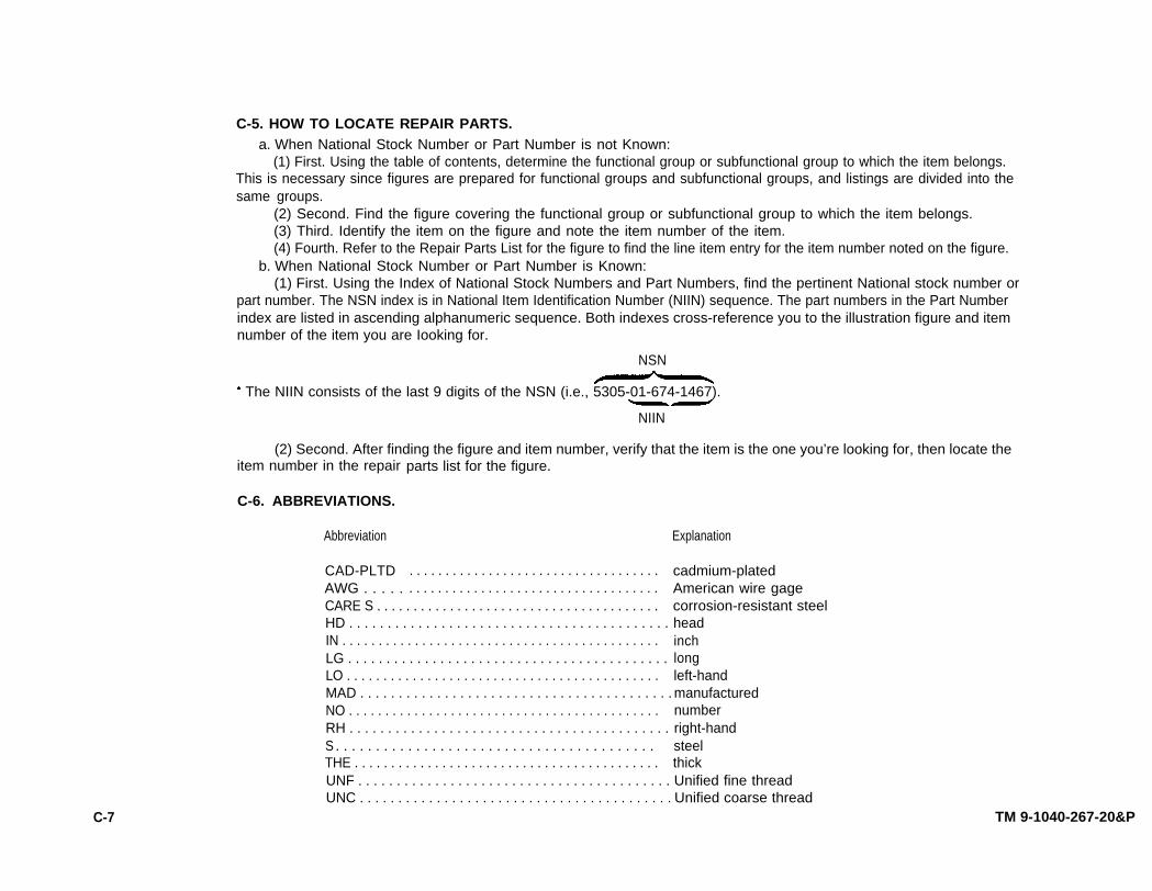
C-5. HOW TO LOCATE REPAIR PARTS.a. When National Stock Number or Part Number is not Known:
(1) First. Using the table of contents, determine the functional group or subfunctional group to which the item belongs.This is necessary since figures are prepared for functional groups and subfunctional groups, and listings are divided into thesame groups.
(2) Second. Find the figure covering the functional group or subfunctional group to which the item belongs.(3) Third. Identify the item on the figure and note the item number of the item.(4) Fourth. Refer to the Repair Parts List for the figure to find the line item entry for the item number noted on the figure.
b. When National Stock Number or Part Number is Known:(1) First. Using the Index of National Stock Numbers and Part Numbers, find the pertinent National stock number or
part number. The NSN index is in National Item Identification Number (NIIN) sequence. The part numbers in the Part Numberindex are listed in ascending alphanumeric sequence. Both indexes cross-reference you to the illustration figure and itemnumber of the item you are Iooking for.
NSN
l The NIIN consists of the last 9 digits of the NSN (i.e., 5305-01-674-1467).
NIIN
(2) Second. After finding the figure and item number, verify that the item is the one you’re looking for, then locate theitem number in the repair
C-6. ABBREVIATIONS.
Abbreviation
CAD-PLTDAWG . . . . .
parts list for the figure.
. . . . . . . . . . . . . . . . . . . . . . . . . . . . . . . . . . .
. . . . . . . . . . . . . . . . . . . . . . . . . . . . . . . . . . .CARE S . . . . . . . . . . . . . . . . . . . . . . . . . . . . . . . . . . . . . . .HD . . . . . . . . . . . . . . . . . . . . . . . . . . . . . . . . . . . . . . . . . .IN . . . . . . . . . . . . . . . . . . . . . . . . . . . . . . . . . . . . . . . . . . . .LG . . . . . . . . . . . . . . . . . . . . . . . . . . . . . . . . . . . . . . . . . .LO . . . . . . . . . . . . . . . . . . . . . . . . . . . . . . . . . . . . . . . . . . .MAD . . . . . . . . . . . . . . . . . . . . . . . . . . . . . . . . . . . . . . . . .NO . . . . . . . . . . . . . . . . . . . . . . . . . . . . . . . . . . . . . . . . . . .RH . . . . . . . . . . . . . . . . . . . . . . . . . . . . . . . . . . . . . . . . . .S . . . . . . . . . . . . . . . . . . . . . . . . . . . . . . . . . . . . . . . .THE . . . . . . . . . . . . . . . . . . . . . . . . . . . . . . . . . . . . . . . . . .UNF . . . . . . . . . . . . . . . . . . . . . . . . . . . . . . . . . . . . . . . . .UNC . . . . . . . . . . . . . . . . . . . . . . . . . . . . . . . . . . . . . . . . .
Explanation
cadmium-platedAmerican wire gagecorrosion-resistant steelheadinchlongleft-handmanufacturednumberright-handsteelthickUnified fine threadUnified coarse thread
TM 9-1040-267-20&P

TM
-9-1040-267-20&P
C-8 C
hange 1
Figure C
-1. M243, M
257, and M259 R
P S
creening Sm
oke Grenade Launcher C

TM9-1040-267-20&P(1) (2) (3) (4) (5) (6) (7) (8)ILLUSTRATION DESCRIPTION QTY(a) (b) NATIONAL INCFIG ITEM SMR STOCK PART INNO NO CODE NUMBER FSCM NUMBER U/M UNIT
USABLE ON CODEGROUP 00 LAUNCHER, GRENADE, SMOKE:
M243, M257, AND M259
C-1 1 PAOOO 1040-01-095-0091 81361 E13-12-90 DISCHARGER, SMOKE GRENADE EA 2
C-1 2 PAOOO 1040-01-095-0092 B1361 E13-12-111 ARMING FIRING UNIT GRENADE DISCHARGER R39, R69 EA 1
C-1 3 PAOOO 2540-01-096-4559 81361 D13-12-40 BOX, STOWAGE, SMOKE GRENADE R69 EA 2
C-1 3.1 PAOOO 1040-01-208-7116 81361 E 13-12-165 BOX, STOWAGE, SMOKE GRENADE R69 EA 2
C-1 4 PAOZZ 5340-01-095-0297 81361 C13-12-65 CAP-PLUG, PROTECTIVE , DUST AND MOISTURE SEAL: DISCHARGER EA 8
CHANGE 1 C-9

C-10
Section II. R
EP
AIR
PA
RT
S LIS
T (C
ON
T).
Figure C
-2. Sm
oke Grenade D
ischarger

TM9-1040-267-20&P(1) (2) (3) (4) (5) (6) (7) (8)ILLUSTRATION DESCRIPTION QTY(a) (b) NATIONAL INCFIG ITEM SMR STOCK PART INNO NO CODE NUMBER FSCM NUMBER U/M UNIT
USABLE ON CODEGROUP 01 DISCHARGER, SMOKE: GRENADE
C-2 1 PAOZZ 5999-01-096-2017 81361 C13-12-99 CONTACT, ELECTRICAL EA 4
C-2 2 XAOZZ B13-12-63,C13-12 BUSHING, CONTACT PIN AND ADAPTER ASSEMBLY EA 481361 -64, C13-12-96
C-2 3 PAOZZ 5330-00-248-3840 96906 MS29513-014 PACKING, PREFORMED SYNTHETIC RUBBER EA 4
C-2 4 XDOZZ 96906 MS35335-65 WASHER, LOCK EXTERNAL TOOTH, CRES. HOLE DIA 0.530 MAX, OD EA 40. 900 MAX
C-2 5 XDOZZ 5310-00-989-5525 96906 MS35691-39 NUT, PLAIN, HEXAGON CRES, 0.500-20 UNF-2B EA 4
C-2 6 XDOZZ 5310-00-176-6341 96906 MS17830-06C NUT, SELF-LOCKING, HEXAGON, CRES, PLASTIC LOCKING INSERT, EA 40. 138-32UNC-3B
C-2 7 PAOZZ 5905-01-094-9838 81361 C13-12-86 RESISTOR NETWORK. FIXED WIREWOUND EA 1
C-2 8 PAOZZ 5310-00-177-1332 96906 MS17830-04C NUT, SELF-LOCKING, HEXAGON, CRES, NO.4-4OUNC-3B EA 4
C-2 9 PAOZZ 5310-00-595-6211 96906 MS15795-803 WASHER, FLAT S, 0.125 ID, 0.250.OD EA 4
C-2 10 XAOZZ 81361 D13-12-78 COVER PLATE EA 1
C-2 11 PAOZZ 5330-00-641-4338 96906 MS52000-4 GASKET RUBBER EA 1
C-2 12 PAOZZ 5935-00-801-6616 96906 MS3102R14S7P CONNECTOR, RECEPTACLE, ELECTRICAL, BOX MOUNTING EA 1
C-2 13 PAOZZ 5305-00-006-9408 96906 MS3212-5 SCREW, MACHINE CROSS-RECESS-PAN-HD, SELF SEALING, S, NO. 4- EA 44OUNC-2A X 0.500 LG
C-2 14 MOOZZ 81349 M23053/5-104-4 INSULATION SLEEVING ELECTRICL, 3/4 IN LG MFD FROM 5970-00- IN 3787-2325
C-11

TM9-1040-267-20&P
SECTION II. REPAIR PARTS LIST (CONT)
(1) (2) (3) (4) (5) (6) (7) (8)ILLUSTRATION QTY(a) (b) NATIONAL USABLE ON CODE INCFIG ITEM SMR STOCK PART INNO NO CODE NUMBER FSCM NUMBER USABLE ON CODE U/M UNIT
C-2 15 PAOZZ 5305-00-071-1322 96906 MS51960-65 SCREW, MACHINE FLAT COUNTERSUNK CROSS-RECESS ND, CRES, NO. 10- EA 832UNF-2A X O.500 LG
C-2 16 PAOZZ 5305-00-054-6652 96906 MS51957-28 SCREW, MACHINE CROSS-RECESS-PAN-HD, CRES, NO. 6.32UNC-2A X EA 1O.375 LG
C-2 17 PAOZZ 5310-00-933-8119 96906 MS35338-137 WASHER, LOCK S, 0.250 OD EA 1
C-2 18 PAOZZ 5940-00-512-1019 96906 MS77074-2 TERMINAL, LUG EA 1
C-2 19 MOOZZ 81361 MIL-W-81044/12 WIRE, ELECTRICAL 16 AWG WIRE SIZE, WHITE 2 FT LG, FABRICATE EA 1FROM BULK WIRE NSN 6145-00-144-0083
C-2 20 PAOZZ 5310-00-619-1148 96906 MS15795-808 WASHER, FLAT S, 0.227 ID, 0.453 OD EA 2
C-2 21 PAOZZ 5310-00-059-9263 96906 MS21046C3 NUT, SELF-LOCKING, HEXAGON, S, NO. 10-32UNF-3B EA 2
C-2 22 PAOZZ 5330-01-096-4551 81361 C13-12-77 GASKET EA 1
C-2 23 PAOZZ 5305-00-988-7840 96906 MS16995-66 SCREW, CAP, SOCKET HEAD, CRES. 5/16-18UNC-3A X 1 IN LG EA 12
C-2 24 PAOZZ 5310-00-184-9562 96906 MS35335-62 WASHER, LOCK FLAT, EXTERNAL TOOTH,S, 5/16 NOM SIZE EA 12
C-2 25 XAOZZ 81361 E13-12-94 DISCHARGE BASE EA 1
C-2 26 PAOZZ 5330-00-252-6050 96906 MS29513-138 PACKING, PREFORMED SYNTHETIC RUBBER, 2.122 IN CENTER HOLE DIA EA 4
C-2 27 PAOZZ 1010-01-246-9930 81361 D13-12-187 TUBE, CANNON: DISCHARGER EA 4
CHANGE 1 C-12


TM9-1040-267-20&P(1) (2) (3) (4) (5) (6) (7) (8)ILLUSTRATION DESCRIPTION QTY(a) (b) NATIONAL INCFIG ITEM SMR STOCK PART INNO NO CODE NUMBER FSCM NUMBER U/M UNIT
USABLE ON CODEGROUP 9999 BULK MATERIAL
BULK 1 PAOZZ 5970-00-787-2325 81349 M23053/5-104-4 INSULATION SLEEVING ELECTRICAL FT V
BULK 2 PAOZZ 6145-00-144-0083 81349 M81044/12-16-9 WIRE, ELECTICAL FT V
SECTION III. SPECIAL TOOLS LIST
NOT APPLICABLE
CHANGE 1 C-15

TM9-1040-267-20&P CHANGE 1SECTION IV. NATIONAL STOCK NUMBER AND PART NUMBER INDEX
FIGURE ITEM FIGURE ITEMSTOCK NUMBER NO. NO. STOCK NUMBER NO. NO.
5305-00-006-9408 C-2 13 5970-00-787-2325 BULK 15305-00-054-6652 C-2 16 5935-00-801-6616 C-2 125310-00-059-9263 C-2 21 5340-00-860-3862 C-4 25305-00-071-1322 C-2 15 5320-00-883-8271 C-4 16145-00-144-0083 BULK 2 5310-00-933-8119 C-2 176210-00-176-4954 C-3 1 5305-00-988-7840 C-2 235310-00-176-6341 C-2 6 5310-00-989-5525 C-2 55310-00-177-1332 C-2 8 5905-01-094-9838 C-2 75310-00-184-9562 C-2 24 1040-01-095-0091 C-1 15330-00-248-3840 C-2 3 1040-01-095-0092 C-1 25330-00-252-6050 C-2 26 1010-01-246-9930 C-2 275940-00-512-1019 C-2 18 5340-01-095-0297 C-1 45310-00-595-6211 C-2 9 5999-01-096-2017 C-2 15310-00-619-1148 C-2 20 5330-01-096-4551 C-2 225330-00-641-4338 C-2 11 2540-01-096-4559 C-1 36240-00-763-7744 C-3 2 1040-01-208-7116 C-1 3.1
FIGURE ITEM FIGURE ITEMFSCM PART NUMBER NO. NO. FSCM PART NUMBER NO. NO.
81361 B13-12-63,C13-12-64,C13-12-96 C-2 2 96906 MS21046C3 C-2 2181361 C13-12-65 C-1 4 96906 MS29513-014 C-2 381361 C13-12-77 C-2 22 96906 MS29513-138 C-2 2681361 C13-12-86 C-2 7 96906 MS3102R14S7P C-2 1281361 C13-12-99 C-2 1 96906 MS3212-5 C-2 1381361 D13-12-40 C-1 3 96906 MS35335-62 C-2 2481361 D13-12-78 C-2 10 96906 MS35335-65 C-2 481361 D13-12-187 C-2 27 96906 MS35338-137 C-2 1781361 E13-12-111 C-1 2 96906 MS35691-39 C-2 581361 E13-12-165 C-1 3.1 96906 MS51957-28 C-2 1681361 E13-12-90 C-1 1 96906 MS51960-65 C-2 1581361 E13-12-94 C-2 25 96906 MS52000-4 C-2 1181349 LC35RT2 C-3 1 96906 MS77074-2 C-2 1881361 MIL-W-81044/12 C-2 19 81349 M23053/5-104-4 C-2 1496906 MS15795-803 C-2 9 81349 M23053/5-104-4 BULK 196906 MS15795-808 C-2 20 81349 M81044/12-16-9 BULK 296906 MS16995-66 C-2 23 98003 SCD20648 C-4 296906 MS17830-04C C-2 8 81361 SC-D-20650-13X-ZE C-4 396906 MS17830-06C C-2 6 81348 W-L-00111/7 C-3 296906 MS20613-4PB C-4 1
C-16


TM9-1040-267-20&P
SECTION II.EXPENDABLE SUPPLIES AND MATERIALS LIST(Continued)
(1) (2) (4) (5)
NATIONALITEM STOCKNUMBER LEVEL NUMBER DESCRIPTION U/M
4 0 7510-00-469-7910 INK, MARKING, STENCIL: BLACK, PRESSURIZED CAN PT(81348) TT-1-1795
5 0 8040-00-082-2508 PRIMER, ADHESIVE: GRADE T, OZ(81349) MIL-S-22473
6 0 8010-00-161-7425 PRIMER COATING: 1 GAL. CAN GL(81348) TT-P-636
7 0 8030-00-823-9116 SEALING COMPOUND: GRADE HV, CC(81349) MIL-S-22473
8 0 8030-01-096-5299 SEALING COMPOUND: GRADE HVV, QT(81349) MIL-S-22473
9 0 3439-00-555-4629 SOLDER, TIN ALLOY: ROSEN CORE, SLSN 60, TYPE SNGOWRP2 1 LB(81348) QQ-S-571
10 0 7510-00-290-2027 TAPE, PRESSURE SENSITIVE ADHESIVE: RO1-1/2 IN. WIDE, 60 YD ROLL(81348) PPP-T-42
D-2

ALPHABETICAL INDEXSubject
A
Arming firing unit, maintenance instructions . . . . . . . . .
B
Box, grenade stowage, maintenance instructions . .
C
. . . . . .
. . . . .
Page
. . 2-48
. . 2-50
Common tools and equipment . . . . . . . . . . . . . . . . . . . . . . . . . . . . . . . . . 2-1Connector, electrical receptacle, discharger, maintenance instruc-
tions . . . . . . . . . . . . . . . . . . . . . . . . . . . . . . . . . . . . . . . . . . . . . . . . . . . . . 2-29Contacts, electrical, discharger, maintenance instructions . . . . . . . . . 2-15
D
Destruction of Army materiel to prevent enemy use . . . . . . . . . . . . . .1-1Differences between models . . . . . . . . . . . . . . . . . . . . . . . . . . . . . . . . . . 1-4Discharger maintenance instructions . . . . . . . . . . . . . . . . . . . . . . . . . . . 2-14
Discharger tubes . . . . . . . . . . . . . . . . . . . . . . . . . . . . . . . . . . . . . . . . . 2 -35Electrical contacts . . . . . . . . . . . . . . . . . . . . . . . . . . . . . . . . . . . . . . . . . 2-15Electrical receptacle connector . . . . . . . . . . . . . . . . . . . . . . . . . . . . . . 2-29Ground wire . . . . . . . . . . . . . . . . . . . . . . . . . . . . . . . . . . . . . . . . . . . . . . . 2-44Resistor . . . . . . . . . . . . . . . . . . . . . . . . . . . . . . . . . . . . . . . . . . . . . . . . . . 2-21
E
(EIR) Reporting equipment improvement recommendations . . . . . . . 1-1Electrical contacts, discharger, maintenance instructions . . . . . . . . . 2-15Electrical receptacle connector, discharger, maintenance
instructions . . . . . . . . . . . . . . . . . . . . . . . . . . . . . . . . . . . . . . . . . . . . . . . 2-29Equipment description and data . . . . . . . . . . . . . . . . . . . . . . . . . . . . . . . 1-2
Differences between models . . . . . . . . . . . . . . . . . . . . . . . . . . . . . . . . 1-4Equipment characteristics, capabilities, and features . . . . . . . . . . 1-2Equipment data . . . . . . . . . . . . . . . . . . . . . . . . . . . . . . . . . . . . . . . . . . . . 1-4Location and discription of major components . . . . . . . . . . . . . . . . 1-2
Expendable/durable supplies and materials list . . . . . . . . . . . . . . . . . . D-1Index-1 Change 1
Subject PageF
Firing unit, arming, maintenance instructions . . . . . . . . . . . . . . . . . ...2-4Forms, records, and reports, maintenance . . . . . . . . . . . . . . . . . . . ...1-1
G
Grenade stowage box, maintenance instructions . . . . . . . . . ...2-50Ground wire, discharger, maintenance instructions . . . . . . . ...2-44
How to use this manual .How to locate repair parts
H
. . .. . . . . . . . . . . . . . . . . . . . . . . . . . . . . . . . . . . . Ill. . . . . . . . . . . . . . . . . . . . . . . . . . . . . . . . . . . . C-7
I
improvement recommendations (EIR), reporting equipment . . . . ...1-1Instructions, maintenance . . . . . . . . . . . . . . . . . . . . . . . . . . . . . . . . . . ...2-1
L
LauncherPrinciples of operation . . . . . . . . . . . . . . . . . . . . . . . . . . . . . . . . . . . ...1-4Service upon receipt . . . . . . . . . . . . . . . . . . . . . . . . . . . . . . . . . . . . ...2-1
Location and description of major components . . . . . . . . . . . . . . . ...1-2
M
Maintenance allocation chart . . . . . . . . . . . . . . . . . . . . . . . . . . . . . . . . . . B-1Maintenance forms, records, and reports . . . . . . . . . . . . . . . . . . . . . . . 1-1Maintenance instructions . . . . . . . . . . . . . . . . . . . . . . . . . . . . . . . . . . . . . 2-1Maintenance procedures . . . . . . . . . . . . . . . . . . . . . . . . . . . . . . . . . . . . . . 2-14M243 launcher, principles of operation . . . . . . . . . . . . . . . . . . . . . . . . . 1-4M257 launcher, principles of operation . . . . . . . . . . . . . . . . . . . . . . . . . 1-4M259 launcher, principles of operation . . . . . . . . . . . . . . . . . . . . . . . . 1-4
TM 9-1040-267-20&P

Index-2 TM9-1040-267-20&P
Subject Page Subject Page
N R
Nomenclature cross-reference list.. . . . . . . . . . . . . . . . . . . . . . . . . . ...1-1 References . . . . . . . . . . . . . . . . . . . . . . . . . . . . . . . . . . . . . . . . . . . . . . . . .A-1Repair parts, special tools list . . . . . . . . . . . . . . . . . . . . . . . . . . . . . . . . .C-0
O Repair parts, special tools, TMDE, and support equipment . . . . . . . .2-1Common tools and equipment.. . . . . . . . . . . . . . . . . . . . . . . . . . . . . .2-1
Organizational maintenance repair parts and special tools list . . . . .C-1Repair parts and materials . . . . . . . . . . . . . . . . . . . . . . . . .Special tools, TMDE, and support equipment . . . . . . . .
Reporting equipment improvement recommendations (EIR)P Resistor, discharger, maintenance instructions . . . . . . . . .
Preparation for storage or shipment . . . . . . . . . . . . . . . . . . . . . . . . . ...2-54 SPreservation materials . . . . . . . . . . . . . . . . . . . . . . . . . . . . . . . . . . . . . .2-54Preservation, packaging, packing, marking, and shippingrequirements . . . . . . . . . . . . . . . . . . . . . . . . . . . . . . . . . . . . . . . . . . . ...2-54Security procedures . . . . . . . . . . . . . . . . . . . . . . . . . . . . . . . . . . . . . ...2-54Type of storage . . . . . . . . . . . . . . . . . . . . . . . . . . . . . . . . . . . . . . . . . . . .2-54
Preventive maintenance checks and services (PMCS)PMCS procedures . . . . . . . . . . . . . . . . . . . . . . . . . . . . . . . . . . . . . . ...2-5
Principles of operation . . . . . . . . . . . . . . . . . . . . . . . . . . . . . . . . . . . . . . ..1-4M243 launcher . . . . . . . . . . . . . . . . . . . . . . . . . . . . . . . . . . . . . . . . . ...1-4M257 launcher . . . . . . . . . . . . . . . . . . . . . . . . . . . . . . . . . . . . . . . . . ...1-4M259 launcher . . . . . . . . . . . . . . . . . . . . . . . . . . . . . . . . . . . . . . . . . ...1-4
. . . . . . . . 2-1
. . . . . . . . 2-1
. . . . . . . 1-1
. . . . . . . . 2-21
Security procedures . . . . . . . . . . . . . . . . . . . . . . . . . . . . . . . . . . . . . . . . . .2-54Service upon receipt . . . . . . . . . . . . . . . . . . . . . . . . . . . . . . . . . . . . . . . . .2-1Special tools, TMDE, and support equipment . . . . . . . . . . . . . . . . . . .2-1
T
Troubleshooting . . . . . . . . . . . . . . . . . . . . . . . . . . . . . . . . . . . . . . . . . . . . .2-5Arming firing unit won’t fire... . . . . . . . . . . . . . . . . . . . . . . . . . . . . . . .2-10Discharger won’t fire . . . . . . . . . . . . . . . . . . . . . . . . . . . . . . . . . . . . . . .2-6Indicator light won’t light . . . . . . . . . . . . . . . . . . . . . . . . . . . . . . . . . . .2-13Scope . . . . . . . . . . . . . . . . . . . . . . . . . . . . . . . . . . . . . . . . . . . . . . . . . . . .2-5
Tubes, discharger, maintenance instructions . . . . . . . . . . . . . . . . . . . .2-35Type of storage . . . . . . . . . . . . . . . . . . . . . . . . . . . . . . . . . . . . . . . . . . . . . .2-39


By Order of the Secretary of the Army:
CARL E. VUONOGeneral United States Army
Chief of Staff
Official:
R. L OILWORTHBrigadier General United States Army
The Adjutant General
DISTRIBUTION:
To be distributed in accordance with DA Form 12-40, Unit Maintenancerequirements for Launcher, Grenade, Smoke, M243, M257, M259.
U.S. GOVERNMENT PRINTING OFFICE : 1994 - 300-421 (00120)


P I N : 0 5 5 2 2 1 - 0 0

This fine document...
Was brought to you by me:
Liberated Manuals -- free army and government manuals
Why do I do it? I am tired of sleazy CD-ROM sellers, who take publicly available information, slap “watermarks” and other junk on it, and sell it. Those masters of search engine manipulation make sure that their sites that sell free information, come up first in search engines. They did not create it... They did not even scan it... Why should they get your money? Why are not letting you give those free manuals to your friends?
I am setting this document FREE. This document was made by the US Government and is NOT protected by Copyright. Feel free to share, republish, sell and so on.
I am not asking you for donations, fees or handouts. If you can, please provide a link to liberatedmanuals.com, so that free manuals come up first in search engines:
<A HREF=http://www.liberatedmanuals.com/>Free Military and Government Manuals</A>
– SincerelyIgor Chudovhttp://igor.chudov.com/
– Chicago Machinery Movers