tm-598 113077 opera,tion and ‘maintenance manual ... · tm-598 113077 opera,tion and...
TRANSCRIPT

TM-598
113077
OPERA,TION AND ‘MAINTENANCE MANUAL
with
ILLUSTRATED PARTS LIST
for
TkANSFOFiMER-RECTIFIER
112-VOLTS DC, 400 AMPERES
MODEL NUMBER TR-4012
Part Number 482085A-2
Part Number 482085A-5
(with 24-Volt DC Power Supply)
manufactured by
.I HOBART BROTHERS COMPANY! ’
POWER SYSTEMS DlVlSlOk , ;;
TROY, OHIO 45373 ‘I L I
1
1
U.S.A.

!
) ‘! I

SAFETY INSTRUCTIONS AND WARNINGS FOR ELECTRICAL POWER EQUIPMEAT
ELECTRIC SHOCK can kill. Do not touch live electrical parts.
ELECTRIC ARC FLASH can injure eyes burn skin cause equipment damage and
I l ‘2 1,: ignite co bustible materiaf. Do not use power cables to break lo/$! and prevent tools from causing short circuits.
IMPROPER PHASE CONNECTION, PARALLELING, OR USE can damage this and attached 'I equipment.
IMPORTANT: - Protect all operating personnel. Read, understand, and follow all instructions in the Operating/Instruction Manual before installing, operating , or servicing the equipment. available for future use by all operators.
Keep the manual
A. GENE=
Equipment that supplies electrical power can cause serious injury or death, or damage to other equipment or property. The operator must strictly observe all safety rules and take precautionary actions. Safe practices have been developed from past experience in the use of power source equipment. While certain practices below apply only to electrically-powered equipment, other practices apply to engine-driven equipment, and some practices to both.
B. SHOCK PREVENTION
--- - ._ Bare conductors, electrically-live
or terminals in the output circuit, or ungrounded, equipment can fatally shock a person. Have a certified
electrician verify that the equipment is adequately grounded and learn what terminals and parts are electrically HOT. Avoid hot spots on machine. Use proper safety clothing, procedures, and test equipment.
The electrical resistance of the body is decreased when wet, permitting dan erous
f currents to flow through it.
equ pmeat, do not work in damp areas. When inspecting or seticing Stand on a dry rubber mat or
dry wood, use insulating gloves when dampness or sweat cannot be avoided. Keep clothing dry, and never work alone.
1. Installation and Grounding of Electrically Powered Equipment
Equipment dr2ven by electric motors (rather than by diesel or gasoline engines) must be installed and maintained in accordance with the National Electrical Code, ANSI/NFPA 70, and other a plicable codes. A power disconnect switch or circuit breaker must 1 Check the nameplate for volta e,
e located at the equipment.
only 3-phase power is 9, frequency, and phase requirements. If
availab e, connect to only two nres of the 3-phase line.
any single- hase rated equipment DO NOT CONNECT the equipment
grounding conductor (lead) to the third live wire of the 3-phase line, as this makes the equipment frame electrically HOT, which can cause a fata? -zzimc.- p-e---
Alwa s connect the grounding lead if supplied in a'power line cable, to t e grounded K swiizkdbox or building ground. separate groundin
If not provided, use a
of the grounding fi Ensure that the current (am erage)
! capacity
ault current situation.
ead 211 be adequate for the worst
details. Refer to the National Electrical Code ANSI/NFPA 70 for
Do not remove plug ground prongs. Use correctly mating receptacles.
' 2.
3.
Output Cables and Terminals
Inspect cables frequently for damage to the insulation and the connectors. not overload
Re lace or repair cracked or worn cables immediately. Do ca les. 1
energized. Do not touch output terminal while equipment i,s
Service and Maintenance ) '! , ' I'
i This e uipment must be maintained in good electrical and mechanical condit on to avoid hazards stemming from disrepair. 4 Report any equipment defect or safet hazard to the super&.sor and discontinue use of the ejuigment untiP its safety has been assured. Repairs should be ma e y qualified personnel only.
Instruction 910082 fmL ~C1OC n---r --3 Page 1

Before inspecting or servicing electrically-powered equipment, take the following precautions:
FIRE AND EXPLOSION PREVENTION ,
Fire and explosion are caused by electrical short circuits, combustible material near engine exhaust pi in unsafe operating or fueling con it ii P
,, misuse of batteries and fuel, or ons.
Electrical Short Circuits and'overloads
Overloaded or shorted either by self
e uipment destruct 4
can become hot enough to cause fires on or causing nearby combustibles to ignite.
For electrically-powered equipment, in particular, input protection to remove short circuited or heavi
rovide primary
equipment from the line. P y overloaded
.Batteries
Batteries may explode and/or give off flammable hydro en and arcing from a ru failures. When ser T!
tured battery can cause fires an 3 ad%$onze acid cing, do not smoke, cause sparking, cr use open
flame near the battery.
Engine Fuel
Use only approved fuel container or fueling system. Fires and . explosions can occur if the fuel tank is not grounded prior to or during fuel transfer.
. completely fill Shut unit DOWN before removing fuel tank cap. Do not tank,
expansion overflow. because heat from the e uipment may cause fuel Remove all spilled fuel
that penetrates the unit. &ME
After clean-up, DIATELY, including any
fumes away with compressed air. open equipment doors.and blow
D. TOXIC FUME PREVENTION
Carbon monoxide - Engine exhaust fumes can kill and cause health problems. Pipe or vent the exhaust fumes to a suitable exhaust duct or outdoors. Never locate engine exhausts near intake ducts of air conditioners.
E. BODILY INJURY PREVENTION
Serious inju Shut DOWN sue 7:
can result from contact with fans inside some equipment.
equipment is equipment for inspection and routine maintenance. When
in o eration use extreme care in doing necessary troubleshooting
F.
and adjustment. E o not remove guards while equiment is operating.
MEDICAL AND FIRST AID TREATMENT
a. Shut OFF all power at the disconnectin before,inspecting or servicing the equ pment. f
switch or line breaker
b. Lock &itch OPEN (or remove line fuses) so that power cannot be turned ON accidentally.
c. Disconnect power to equipment if it is out of service.
d. If troubleshooting must be done with the unit ener ano,ther
zed, have
"arid pro d erson prese t'tiho is trained in turning o f the equipment
9 ding or calling for first aid. i?
First 'aid facilities and a qualified first aid person should be available for each shift for immediate treatment of all injury victims. Electric shock vzctims should be checked by a ph sician and taken to a hospital immediately if any abnormal signs are o served. B
i
.I
1
Call physician immediately. Seek additional assistance and use First Aid techniques recommended by American Red Cross until medical help arrives.
1 ' IF BREATHING : down.
IS DIFFICULT,_g5ve ------ .- ---- FOR ELECTRICAL SHOCK oxy en,
f if,available, 'a
? d have vie
turn o f power. Remove vie i.m; if not tim lie1 t ',
breathing, begin artificiai'respiration, preferably mouth-to-mouth. 'If I
no detectable pulse, Squad immediately.
begin external heart massage. Call Emergency Rescue
G. EQUIPMENT PRECAUTIONARP'LABELS .,
Ins rep ace all abels that cannot be easily rea
E ect a II precautionary Labels on the equi rnt monthly. Order and
EMERGENCY FIRST AID

._ _ _
TM-598
j INTRODUCTION
1. Scope
This manual contains information and’instr;uctions for a 112-V DC Transformer-Rectifier, manufactured by Ho-
ba’;t ,B$;thers Company, Power SystyS bivision, Troy, Ohio 45373, U.S.A.
2. Purpose
The purpose of the manual is to provide information and instructions to experienced operators, electricians, and
mechanics who have not previously seen or operated this machine. The manual is not intended to be a text book
on electricity, nor electronics.
3. Contents and Arrangement
The manual is divided into 3 chapters. Each chapter is divided into as many sections as required. Each section
begins with page 1, and each page is identified by chapter, section and page number, in the lower outside
corner. Illustration numbering is also grouped by sections.
When a reference is made to material which is located in the same section, the material is identified by paragraph
location only; example: (Para. 1, A). When referenced material appears in a different section, it is identified by
chapter, section and paragraph location: example: (2-l ; Para.1, A). The same method applies to illustrations which
are identified by figure numbers; examples: (Fig. 81, or (2-1; Fig. 8).
4. Service Information
If you have any questions concerning your Hobart Power Systems Division equipment, you are invited to contact
our Service Department by mail, telephone or TWX at:
Hobart Brothers Company Power Sytiems Division
Service Department
Troy, Ohio 45373 U.S.A.
Telephone: Area Code (513) 3396276
TWX : 81 o-456-2907
1 Nov 30177 Introduction
Page 1


___.-. -... . .._.. -. _.. .- .-...
SUbJECT
lntroductipn
w I I TM-598
TABLE OF CONTENTS
lj,“’
I. General I
2. Transformer-Rectifier Assembly’
A. Control Panel Assembly
8. Electrical Components
(I ) Terminal board
(2) Load contactor
(3) Transformer
(4) Heat sink assembly
(5) Overload module
(6) Overvoltage module
(71 Base
(8) Power supply
Preparation for Use
I. General
2. Inspection
/ 3. Installation
A. General
8. Mounting
C. Connection
(I) Input (482085A-2)
(2) Input (482085A-5)
1 Nov 30177
CHAPTER/SECTION PAGE
I
I-o
I-l
I-2
Contents
Page 1

:, TABLE OF CONTENTS (CONTINUED)
TM-598
SUBJECT CHAPTER/SECTION PAGE
(3) output 1 *
Operation ‘i.i, 1, ” ( 1, ‘I
I. Preparation for DC Power Delivery
2. DC Power Delivery
3. Discontinue Power Delivery
Servicing
Maintenance
I. General
2. Lubrication
3. Inspection
4. Cleaning
Adjustment/Test
I. General
2. Test
3.
A. Preparation for Test
8. ‘Operational Test Procedures
C. Test Silicon Diodes
Adjustment
A. Ammeter Shunt
B. Overvoltage Trip Point
Troubleshooting
I. General
.I
2. Troubleshooting Chart
A. Description !
( ‘!
I-2 3
I-3 I
2-0,
2-I
2-2
2-3
3
I
I
I
I ’
’ I
C+tents
Page 2
Nov 30177

._ _ _. _. . . . .._- . -. .,_ . _,
I 1 TM598
‘,, TABLE OF CONTENTS (CONTINUED)
SUBJECT
1 B. How to Use Troubleshooting Chart
I ’ (1 6”. ~ I> 3. Equipment for Troubleshooting
4.’ Safety I
5. Parts Replacement
CHAPTER/SECTION PAGE
2-3 I
I
1
I
6. Check Connections and Leads
7. Schematic Diagram
Repair 24
I. General
2
2
I
2. Removal and Installation I
A. Removal Procedures I
B. Installation Procedures 1
3. Parts Replacement I
A. Access
8. Parts Removal
C. Parts Installation
D. Fan Installation
4. Workmanship
5. Connection Diagrams
Illustrated Parts List 3-o
Introduction 3-I
I. General
2. Purpose
.I
3. Arrangement
4. Explanation of Parts List
\ Nov 30/77
! , iI,
1
I
2
2
2
2
1
1
1 .
1
I
’ /
*I ’
Contents
Page 3

I TM-598
;, TABLE OF CONTENTS (CONTINUED)
SUBJECT CHAPTER/SECTION PAGE
A. Cpntents
8.1 ‘hts List Form
3-I I (
lI,“’ 1
(I) Figure Item No. colump 1
(2) Hobart Part Number column 2
(3) Nomenclature column ’
(4) Eff (Effective) column
(5) Units Per Assembly column
Manufacturer’s Codes
1. Explanation of Manufacturer’s (Vendor) Code List
Parts List
1. Explanation of Parts List Arrangement
Numerical Index
I. Explanation of Numerical Index
Coptents
Page 4
3-2
3-3
34
Nov 30/77

.
TM-598
LIST OF ILLUSTRATIONS
CHAPTER/
SECTION , FIGURE NUMBER
PAGE
NO. 3 TITLE
l1”’ ’ Transformer-Rectifier (1 I2 V DC)
Specifications and Capabilities
/ Control Panel Assembly
T-R Components (Front and Rear Views)
T-R Components (Side Views)
T-R Components (Top View from Front)
I-C $1) ’
I-I
I-l
I-I
I-I
I-I
I-2
I-2
I Input Connection Diagram
2 Output Cable Installation
I-3 I Control Panel Assembly 2
2-I No Illustrations
2-2
2-2
I Ammeter Shunt Adjustment 2 Overvoltage Adjusting Rheostat
4
5
2-3
2-3
2-3
2-3
T-R Schematic Diagram 3 Control Panel Assembly 4 Troubleshooting Chart (3 Sheets) 5thru7 24-Volt Power Supply 8
24
24
24
24
24
T-R Connection Diagram
Power Module Connection Diagram Control Panel Connection Diagram
Overload Module Connection Diagram
Overvoltage Module Connection Diagram
3-I No Illustrations
3-2 No Illustrations
3-3
3-3
3-3
3-3
Transformer-Rectifier Assembly 2 Power Module Assembly 6 Control Panel Assembly 8 24-Volt Power Supply IO
34 No Illustrations
! ’
, ‘! I ’ I
\ Nov 30/77 !, Contents
Page 5

,’
(1 1”. I ’
’ I

TM-598
CHAPTER I. DESCRIPTION/OPERATION
SECTION I. DESCRIPTION 1 9
I. G&ner& I/,“’
The transformer-rectifier, hereafteq referred to as a T-R, is a compact, enclosed, power-supply unit employing a
transformer and semiconductor diode components to convert 200-Volt, 400-Hz input to 112~Volt DC output
1 power (see Fig. I). It has many uses including aircraft servicing, testing, etc.
This manual covers two nearly identical units: part numbers 482085A-2 and -5. The only difference between the units is that the -5 has a 24Volt power supply. This power supply furnishes the 24 Volts DC required to prevent
the generator’s plug-interlock relay from shutting down the generator when the T-R is used as a free-standing unit.
When a 112.Volt T-R is furnished with a generator set, it is hard-wired in at the factory and provision is made to
bypass the generator’s plug-interlock relay and the unit furnished is 482085A-2. If a T-R is furnished to be used
with an existing generator and to be connected PER,MANENTLY to that generator by the user, the unit furnished
is also 482085A-2. However, if a T-R is furnished to be used TEMPORARILY with a generator, or interchangeably
with several generators as a free-standing unit, the 24Volt source is necessary to avoid repeated internal wiring
changes to the generators and the unit furnished is 482085A-5. --- --. -
2. Transformer-Rectifier Assembly
The T-R consists of six main assemblies plus side panels and top, which make up the weatherproof enclosure.
Terminal boards, cables, and other miscellaneous items complete the assembly. Main assemblies are identified
as follows:
Transformer Heat sink (rectifier)
Power module
Control panel
Overvoltage module
Base .
For purposes of orientation, the control panel is considered to be at the FRONT of the T-R. The load contactor
and fans are at the REAR. RIGHT and LEFT are determined by observing the unit from a position at the REAR.
Thus the output terminals are on the LEFT side.
The T-R is designed to convert the output of 115/200-Volt AC, 400.Hz, 3-phase generator to I IZVolts DC,
‘primarily for operation and/or testing of aircraft on-board electrical equipment. AC input voltage is reduced
by a transformer assembly and changed to DC by a 12-diode rectifier identified as a heat sink assembly. At
100% duty (steady operation), the unit is rated at 400 Amperes. Refer to Fig. 2 for specifications and capabili-
ties.
‘Solid state current and voltage sensing modules serve to protect the T-R and aircraft by disconnecting the load
under conditions of overload and/or overvoltage. Thermostatic switches provide protection against overheating.
Two, 200-Volt AC, motordriven fans provide cooling for internal components. Air is drawn in over the heat sinks
and discharged at the power module end.
1 I
Nov 30177 l-1
Page 1

TM -598
. .
Transformer-Rectifier (I 12-V DC) Figure 1
A. Control Panel Assembly
Refer to Fig. 3. The control panel (12) serves a dual function. It provides a mounting panel for instruments
and controls, and when hinged downward, serves as a door for access to internal components. Two captive-
screw type fasteners (I 1 secure the panel in closed position. Louvers (2) on each side of the panel admit air
to the fans. An instrument light (41, controlled by a toggle switch (IO), provides illumination for controls
and instruments. IZVolt DC power for operation of the light is supplied by the generator-set engine circuit
through a 2-Ampere fuse (9). A three-position toggle switch (71 controls operation of a load contactor in the
input circuit The switch is spring loaded in the top ON, or start position.
An indicating light (6) glows green when the load contactor is closed,to indicate that 112.Volt DC is available
at the output terminals. A fuse (8) protects the II5Volt AC, load contactor operating circuit.
A voltmeter (3) indicates T-R output voltage in a range of 0 to 150 Volts DC. The DC ammeter (5) has a range
of 0 to 1200 Amperes.
.I
Other items are mounted on the inner surface of the control panel and are not visible unless the panel is
opened. A resistor (13) is connected in the load contactor holding circuit to limit current flow to approximate-
ly 0.5 Ampere. Another resistor (14) is connected in series with a variable rheostatJI6). The rheostat provides I
a means of adjusting DC input power to the overvoltage module (5, Fig. 4) to allofl,adjustment of the over- ’ b 1 voltage trip point.
I
I-l i
Nov 30/77 -
Page 2 !,

-.. . _’
TM-598
./
;,
TRANSFORMER-RECTIFIER
Part number .................................................... 482085A-2 and -5
Model,number .................. i ....................................... TR-4012
PH&AL l/,“’ ’
Overall dimensions I
Length.. ....................... . ............................ .34inches(864mml
Width ...................................................... 20.3/4 inches (527 mm)
Height .................................................... 12-7/8 inches (327 mm)
Mounting dimensions ....................... 24-l/8 x I6 inches (613 x 406 mm) center to center.
Four 3/8-I6 inch tapped mounting holes
Weight approximately ........................................... 280 pounds (I 27.0 kg)
ELECTRICAL
Input
Line volts ...................................................... 115/200 Volts AC
Cycles per second ........................................................ 400 Hz
Amperes .......................................................... 132 Amperes
Kilowatts ............................................................ ..44k W
output
Volts ............................................................ 100VoltsDC
Load rating ........................................................ 400 Amperes
Duty cycle ................................. . ........................... 100%
Overload rating ............................................... 1000 Amperes, 30 Sec.
Kilowatts (steady state load) .................................................. 42 kW
Recommended output cable size for normal aircraft servicing .............................. 4/O
Specifications and Capabilities Figure 2
B. Electrical Components
Electrical components of the T-R, other than the control panel which was described above, are illustrated in
Figs. 4 through 6. A brief description of the function of each component is given here. Theory of operation
will be covered in the description where necessary.
(I ) Terminal board
The terminal board (4, Fig. 41 provides connection terminals for thethree-phase II5/200-Volt input.
Since this is a line-to-line installation, a neutral terminal is not requir@d. ‘I ’ I
1 Nov 30177 ,
I-1
Page 3

.
TM-598
i i
(Control Panel Open)
I. Screw fastener
2. Air inlet louver
3. DC voltmeter
4. Instrument panel light
5. DC ammeter
6. Contactor ON indicating light
7. Contactor control switch
8. Fuse (2 A) (I 15-V AC circuit)
9. Fuse (2 A) (12-V DC circuit)
IO. Light switch
II. Hinge
12. Panel
13. Resistor (200 Ohm, 25 Watt)
14. Resistor (250 Ohm, 100 Watt)
15. Diode bridge rectifier
16. Rheostat
.I
1
Control Panel Assembly Figure 3
1 ’
) ‘i I ’ I
‘-1 Page 4
Nov 30177

(2) Load, contactor
The load contactor (13, Fig. 41 is a sealed unit similar to the one used on a Hobart generator set. It con-
tains four sets of contacts and an operating coil. The three larger sets of contacts conduct the input
power to the transformer. A small, auxiliary set is connected in the II5-Volt input holding circuit to
L the rectifier (15, Fig. 31, which supplies direct current for energization of the load contactor operating
1 ‘$1’ ) coil. In operation, the Ioac(contactor is closed’by holding the contactor control switch (7, Fig. 3) in spring-loaded ON (up) position momentarily. In this position, the switch connects 115Volt AC power
directly to the rectifier (15, Fig. 31, which in turn supplies DC power to the contactor operating coil
and closes all contacts in ih e load contactor. When the control switch (7, Fig. 3) is released, it auto- matically returns to center ON position and 1 I&Volt current is maintained to the rectifier, indirectly,
through a resistor (13, Fig. 31 and the auxiliary contacts in the load contactor. This circuit is arranged
in such a manner that in case an overloaded condition develops, the II5-Volt input to the rectifier is
sent directly to ground through a relay in the overload module. The load contactor is thus opened be
--cause the holding circuit has actually been short circuited. The resistor (13, Fig. 3) limits current flow in the holding circuit to 0.5 Ampere and thus prevents damage to any components.
(3) Transformer
The primary coils of the transformer (6, Fig. 4) consist of three sets of double windings. There are 6
secondary windings; 3 connected in wye, and 3 connected in delta. Normal input voltage is 200 Volts
AC and normal output is approximately I I8 Volts DC at no load. Output voltage gradually decreases
as load is increased. At 400 Amperes load the output voltage is approximately 100 Volts DC.
(4) Heat sink assembly
The heat sink assembly consists of two heat sink subassemblies (2 and 7, Fig. 4) mounted on two cross
member supports and attached by brackets and round head screws. Observed from the rear of the T-R,
the positive heat sink is on the RIGHT and the negative on the LEFT.
Each heat sink subassembly consists of a fan, a thermostatic switch, 6 diodes, and the heat sink which is
a section of multi-finned, aluminum extrusion, 25 inches (635 mm) ‘long. The fan assembly (IO, Fig. 4)
is mounted on the rear of the heat sink. A five-blade, 4-I/4-inch (108 mm1 dia. fan draws cooling air
over the diodes at a rate of 180 cubic feet (5 m3) per minute at 5300 RPM. The fan motor is rated
at 200 Volts AC, 400 Hz. Input power is 33 Watts, 0.3 Ampere. The thermostatic switch (I, Fig. 4)
mounted on the front end of the heat sink, performs a function similar to an overload relay. The
switch causes the load contactor to OPEN by interrupting the contactor holding circuit when an over-
loaded (or other fault) condition causes ambient temperature to rise to approximately 230 deg F (I IO
deg C). The switch closes at approximately 210 deg F (88 deg C).
Two hexagon bars (I I, Fig. 61, threaded at each end, serve as bus bars to conduct current from the
positive (right) heat sink to the positive terminal on the left side of the T-R. The bars pass through holes
in the negative heat sink and are protected from shorting by screw-mounted, insulating plates. Bars are
threaded into the positive heat sink body and funher secured by aluminum nuts. Two aluminum nuts
on the left end of the forward bar are used to attach one of the leads to the DC ammeter. The other
ammeter lead is attached to the same bar on the other side of the negative heat sink by a screw. The
portion of the bar between the lead attaching points serves as a shunt for the ammeter. The shunt
is adjustable by changing the location of the two aluminum nuts.
Two hexagon bars (4, Fig. 6) similar to the positive bars, but shorter, are attached to the negative heat
sink in the same manner as positive bars. They conduct current to the negative output terminal. Each
diode is attached to the heat sink by a washer-nut. 1 ‘i I ’ I
i Nov 30177 I-I IL
Page 5

TM-598
.I
I-I\
Page 6
I. Thermal overload relay 9. Bus bars
2. Negative heat sink
3. Output terminals
4. Input terminal board
5. Overvoltage protective module 6. Transformer
7. Positive heat sink
8. Diode leads
10. Fan
I I. Deleted
12. Overload protective module
13. Load contactor
14. Overload current transformer (Phase Bl
15. Overload current transformer (Phase Al
T-R Components (Front and Rear Views)
Figure 4
I> Nov 30177

I2
TM-598
I. Thermal overload relay
2. Negative heat sink
3. Positive output terminals 4. Negative output terminals 5. Negative diode
6. Fan
7. Overload current transformer (Phase A)
8. Overload current transformer (Phase C1
9., Input terminal board IO. Positive heat sink
I I. Positive diode 12. Overvoltage module mounting bracket
13. Overload module
1 T-R Components (Side Views) ‘.
Figure 5 I ‘1 ’ I
\ Nov 30177 l-1
Page 7

TM-598
1. Fan 2. Load contactor
3. Negative heat sink
4. Negative output terminals
5. Positive output terminals 6. Ammeter shunt
7. Input terminal board
8. Control panel
9. Thermal overload relay
10. Overvoltage module Il. Positive output bus bars 12. Positive heat sink
13. Power supply (24 V DC)
T-R Components (Top View From Front)
Figure 6
‘,
) ‘i,
i I-I
Page 8
Nov 30177

&g@j 1 TM-598
(5)’ Overload module
The overload module (12, Fig. 41 contains solid-state circuitry which interprets signals from three cur-
rent transformers (,I4 and 15, Fig. 4, and 8, Fig. 5) and functions to close a relay when an overload con-
,’ .dition is detected in the T-R main circuit. The normally open relay contacts are connected to the load
I t/l! contactor I ISVolt AC holbing circuit so that when relay contacts are closed by an overload condition,
the load contactor holding circuit is shot-t circuited and the load contactor opens for lack of holding
power. T-R output power,is thus automatically disconnected. Relay contacts return to normally open
position when the overload is removed by load contactor opening. A 200-Ohm, 25-Watt resistor (13,
Fig. 3) limits current flow in the load contactor holding circuit when it is short circuited. Twelve-Volt
DC from the engine circuit provides operating power for the overload relay. This circuit is protected by a
2-Ampere fuse. The load contactor 1 IBVolt operating circuit is protected by another 2-Ampere fuse.
(6) Overvoltage module
The overvoltage module (5, Fig. 4) is another protective device with solid state circuitry,which causes a
normally CLOSED relay to OPEN under a condition of overvoltage in the T-R output circuit. The relay
is connected in the ground circuit of the I I5-Volt AC load contactor holding circuit. When an over-
voltage condition causes the relay to OPEN, the load contactor holding circuit is broken and the con-
tactor opens automatically to shut off the T-R.
(7) Base
The T-R base consists of a metal plate mounted on two steel channel bars which extend the full length
of the plate on each side. Three shorter channel bars are welded at right angles between the frame side
bars to give the plate support and rigidity. Four, 3/8-l 6 tapped mounting holes in the base are located
I6 inches by 24-l/8 inches (406 mm by 613 mm), center to center.
(8) Power supply
Furnished on T-R part number 482085A-5 only. This power supply (13, Fig. 6) furnishes the 24.5 Volts
DC required to prevent the generator’s plug-interlock relay from opening and shutting down the genera-
tor.
i Nov 30177

i

TM-598
SECTION 2. PREPARATION FOR USE
1. General
The T-R requires no special preparation for use, other than inspection; mounting, as required; and/or connec-
tion, a required. I 10 7, li,“’
2. Inspection
A. Inspect exterior for shipping damage such as broken lights or instrument lenses, damaged sheet metal, etc.
8. Open the front control panel and rear access panel by loosening screw-type fasteners.
C. Inspect interior for foreign materials such as rags, shipping papers, etc.
3. Installation
A. General
When the T-R is supplied as part of a generator set, it is properly mounted and connected.
8. Mounting --:. k
T-R mounting supports, complete with hardware, are available in kit form from Hobart Brothers Company
at a nominal cost. These kits provide T-R mounting arrangements for truck or trailer-mounted generators
I as well as self-propelled. If the recommended kit is not to be used, proceed as follows:
(1) Select a location in which the T-R package will not interfere with service and maintenance operations required for the vehicle, or-generator set on which it is mounted. Many Hobart self-propelled generator
sets provide a mounting space on the right side of the drivers compartment; on rear fenders, or behind the drivers compartment.
(2) Mount the T-R so that the front panel is easily visible and accessible for adjustment. A clear area at
both front and rear should be provided so that access panels may be opened fully and easily. I.
(3) Provide mounting holes in solid material to accommodate 3/8 in-16 screws, and locate them 24-l/8 .’
inches by 16 inches (613 mm by 406 mm), center-to-center. The 24-l/8 inch (613 mm) dimension is ..
lengthwise of the T-R. Also provide for air flow to transformer coils through the three openings in the
base.
(4) If mounting is on a solid steel plate, provide an access hole for input cables to the T-R, directly under or
near the input terminal board (l-l ; 7, Fig. 6).
(5) Position the T-R in its mounted position and align mounting holes. Attach with 3/8-16 screws and lock-
washers.
%. Connection
(1) Input (482085A2)
.I As stated above, input leads are connected when the T-R is supplied as part of a generator set. If input
connecton is required, proceed as follows: _’ . . 1 hi , I
- . ..a- -. ::_ / . . _..-. ..-e.. . .- ._.. -_-_ 1 -- .._ _d._ - -
-
1 Nov 30/77 l-2
Page 1

TM-598
(a) Select a convenient point in the generator output circuit BETWEEN the generator and the load
contactor’for attaching size No. 2 cables to output phases A, 8, and C. Many Hobart generator
sets are equipped with a convenient terminal block for this purpose.
(b) Measure the distance between the connection point and the input terminal board on the T-R to
dgkermine length of cable required., ’ I 10 ~ It
(c) Fabricate cables with terminations. Route cables through the bottom of the T-R and connect to
terminal board (1-l ; 4, Fig. 41, Input terminals are identified, A, 8, and C. Connect input lead from
phase A to terminal A, 8 to B;,etc. A large neutral N lead is not required; however, a No. 10 wire
should be connected from the generator N. terminal (or lead) to the ground stud on the T-R input
terminal board.
NOTE: When the T-R (482085A-2) is installed by the customer, it is necessary to remove
jumper lead on terminal strip in generator voltage regulator, Follow instructions
on plate located near terminal strip. Refer to generator set manual.
(d) If this T-R is wired into a generator set WITHOUT another T-R, the 70.inch (1778 mm) Brown-
Yellow lead must be connected to a positive 12.Volt DC source (e.g. generator engine circuit). If it
is to be used WITH another T-R, the Brown-Yellow lead may be connected to pin 1 of plug 6PL on
the other T-R (which is 12 Volts DC).
(2) Input (482085A-5)
Since this T-R is to be used as a free-standing unit (see l-l; Para. 1). the customer must connect it to a
receptacle connector which mates with the generator’s output cable plug. This customer-furnished recep-
tacle connector, AN31 14-18, should be mounted on a solid base, in a convenient location, and connected
to the T-R as follows:
(a) Refer to Fig 1. Connect three No. 2 size cables from the T-R input terminal board to the receptacle connector: A to A, 8 to B and C to C, as labeled.
l- 1
Page 2
-11’2 V. TRANS.- RECT. (Tap View)
r-, -/-24V. POWER SUPPLY
400 HZ. GENERATOR
I I
+--NO.2 CABLE
e
INPUT RECEPTACLE
-_ - I ‘i,
Input Connection Diagram
Figure 1 Nov 3Ol77

- .( -_ .. - -.-,- . . -..-” -..._._ .__.__ ._._. . . . .____..____ ._._. _. _.
TM-598
(b) Connect a No. 10 Wire from receptacle terminal N to the ground stud in the T-R.
, (c) Use a jumper wire to connectterminals E and F on the receptacle.
’ ‘@” l(d) Locate the White-Blue 3,’ ire’ (coiled on the power supply in the T-R) and connect it to terminal E
or F on the receptacle.
I ,(e) Connect the Brown-Yellow lead to a positive 12.Volt DC source (e.g. generator engine circuit).
(3) output
T-R output cables are not normally supplied unless specifically ordered. For normal aircraft service,
use 4/O size cable for positive and negative (see Fig. 2). For other applications where large loads are
involved, it is recommended that two, or even three 4/O cables be used.
.
Output Cable Installation
Figure 2
\ Nov 30177 l-2
Page 3

I’ , I 1”)’
! ’
I ‘!, ’ I’

TM -598
‘SECTION 3. OPERATION
1. Preparation for DC Power Delivery ,
SM&nd prepare the generator se d’ &power delivery the same as for 409Hz use.
NOTE: 409.Hz, AC power may also be delivered to an aircraft at the ime time 11ZVolts DC is
y: being delivered. However; the combined loads should not exceed the rated capacity of the / generator set.
2. DC Power Delivery
A. Connect DC output cable plug connector to aircraft receptacle connector. Be sure good connection is made.
B. Operate generator-set controls, as instructed by the applicable manual, to produce 115.Volts AC, 400.Hz out-
put.
C. If illumination is required at the T-R control panel, turn instrument light (4, Fig. 1) ON with switch (10).
D. Close the T-R load contactor to deliver power to output cables by momentarily holding contactor control
switch (7) in top, ON position until indicating light (6) glows. Release switch and’allow it to return to center,
ON position.
E. Remember that an overload; overvoltage, or overheating will cause the load contactor to disconnect the load
and turn OFF the indicating light (6). If shutdown occurs, check for condition that caused it and remedy be.
fore restarting the T-R.
3. Discontinue Power Delivery
A. Place contactor control switch (7, Fig. 1) in OFF position.
B. Disconnect output cable at aircraft.
WARNING: DO NOT DISCONNECT CABLE WHILE POWER IS ON. LETHAL ELECTRICAL SHOCK
HAZARD EXISTS. ALSO, OPENING THE CONNECTOR UNDER LOAD CAUSES ARC-
ING AND PITTING OF CONNECTOR PARTS.
C. Operate generator-set controls as instructed in applicable manual.
1 Nov 3Of77 l-3 s
Page 1

(Control Panel Open)
1. Screw fastener
2. Air inlet louver
3. DC voltmeter
4. Instrument panel light
5. DC ammeter 6. Contactor ON indicating light
7. Contactor control switch
8. Fuse (2 A) (115-V AC circuit)
9. Fuse (2 A) (12-V DC circuit)
10. Light switch
11. Hinge
12. Panel 13. Resistor (200 Ohm, 25 Watt) 14. Resistor (250 Ohm, 100 Watt) 15. Diode bridge rectifier
16. Rheostat ,
TM -598
I 1
i l-3,
Page 2 .
Control Panel Assembly
Figure 1
I L!, ’ I
Nov 30177

0 m I- TM-598
_ --- - --.
T- ‘. CHAPTER 2. SERVICING
SECTION 1. MAINTENANCE
1. General ,
‘I,’ ( ’ 1”. !I,“’ To make certain the transformer-rectifier is ready for operation at all times, it must be inspected and maintained
systematically and regularly so that any defects will be discovered and corrected before they result in serious dam-
age or complete failure of the equipment
WARNING: STOP OPERATION IMMEDIATELY IF A SERIOUS OR POSSIBLY DANGEROUS FAULT
IS DISCOVERED.
2. Lubrication
The T-R requires no lubrication.
3. Inspection
A periodic inspection schedule should be established and maintained. If the T-R is part of a generator set, in-
spections should be scheduled to coincide with similar inspections for the parent machine. Inspect as follows:
A. Open front control panel and rear access panel. Remove top cover.
WARNING: BE SURE NG INPUT POWER CAN REACH THE T-R. LETHAL ELECTRICAL SHOCK HAiARD EXISTS.
B. Inspect leads and cables for deteriorated or damaged insulation.
C. Check all accessible terminals and connectors for security.
D. Visually inspect all components, terminals, etc., for discoloration and evidence of overheating caused
by loose connections, etc.
E. Check both fuses located on control panel.
4. Cteaning
Use dry, compressed air to clean the interior of the T-R each time it is inspected. _
.I
t Nov 30177
/
i
;
i
4
4
I
L
2-l
Page 1

,’
I 1’. I ”
.I
’ I

TM-598
;; / SECTION 2. ADJUSTMENT/TEST
1. General
This Section contains information for,t,esting and adjusting the T-R after major parts replacement, or repair.
, h ‘& ,’ ’
I I, 2. Test
The following test procedures ma $ be used for testing the T-R following repair, or for checking performance.
, A. Preparation for Test
(1) Connect the T-R to a load bank using two each, size 4/O cables from each output terminal to the load
bank rather than single 4/O cables ordinarily used for aircraft service. I
NOTE: It is recommended that this higher capacity output cable arrangement be used for applications
where very large loads are connected to the T-R.
(2) Check diode leads. Make certain they are not touching bus bars.
(3) Make certain that each transformer bus has clearance between windings and other busing.
6. Operational Test Procedures
(1) Start generator set and adjust voltage to 115/200 Volts AC.
(2) Operate the T-R by placing switch (l-3; 7, Fig. 1) in top ON position momentarily, then release. Green
indicating light should glow to indicate power is available at output terminals.
(3) Observe voltmeter (3). It should indicate approximately 118 Volts DC. Attach a master voltmeter and
compare meter reading. Voltmeter should be accurate to within plus or minus 2%.
(4) Observe operation of fans and check direction of rotation. Air intake is at control panel end (front).
Exhaust is at power module end (rear). If fan rotation is incorrect, reverse the connection of any two fan input leads.
(5) Check adjustment of ammeter shunt.
(a) Adjust the load bank to apply a load of EXACTLY 400 Amperes. Use the load bank ammeter, or a master ammeter.
(b) Observe the T-R ammeter (l-3; 5, Fig. 11. At 70 deg F (21 deg C) ambient temperature, it should indicate 400 Amperes.
NOTE: The aluminum bus bar, a portion of which serves as a shunt, is sensitive to both ambient
temperature, and current-induced, thermal changes. This means that under sustained heavy
loads the ammeter reading could change from the reading indicated at the beginning of a power delivery period.
,
(c) If adjustment is required, refer to Ammeter Shunt Adjustment, Para. 3, A. ’
I ‘!, L #,
\ Nov 30177 i> 2-2
Page 1

TM-598
(6) With 406Ampere load, observe generator-set ammeter. Input current to the T-R should be approximately
136 Amperes. Observe DC output voltage, on T-R voltmeter. Indicated voltage should be approximately
106 Volts DC.
(7) Test overvoltage module 1 /’ I ” ( 1 I”. l1,“.’
(a) Operate switch (7) to close load contactor. No load is required.
(b) Ob,serve T-R output voltmeter!.and gradually increase AC input voltage by adjusting the genera-
/ tor-set voltage control rheostat
(c) Overvoltage module should function to open the T-R load contactor when output voltage reaches
approximately 128 to 132 Volts DC. Module should function in 2 to 10 seconds after trip voltage
is reached.
(8) Test thermal overload thermostatic switches (l-l; 1, Fig. 4)
(a) Use an external switch or jumper lead to disconnect each of the two thermostatic switches. This
test is to make certain switches are connected properly and that they will open the load contactor
in case of overheating.
9-s - -; (b) Load contactor should open when a thermostatic switch is disconnected.
(9) Test overload module
(a) Use a jumper lead to short-out the thermostat switches.
(b) Apply a sustained minimum load of 1000 Amperes to the T-R. The overload module should func-
tion to open the load contactor within 30 seconds.
NOTE: A line current (input) of 328 Amperes is required to produce 9:9 Volts AC across the burden resistors for this test.
‘CAUTION: DO NOT RUN THIS TEST FOR MORE THAN 2 MINUTES.
(c) Remove’jumper lead across thermostat switches.
(10) Test power supply (482085A-5 only)
(a) With 115Volts AC 466HZ input, check output of power supply (l-l; 13, Fig. 6). Should be 24
to 28 Volts DC.
(b) Apply 366Ohm load to T-R output. Voltage should not fatl below 24 Volts DC.
C. Test Silicon Diodes
CAUTION: DO NOT APPLY x MEGGER OR ANY HIGH POTENTIAL TEST EQUIPMENT IN ANY
MANNER THAT SUBJECTS THE SILICON DIODES AND OTHER COMPONENTS TO
ABNORMAL VOLTAGES. SILICON DIODES MUST BE ISOLATED OR SHORTED WITH
.I EXTREMELY SHORT LEADS. SUCH TESTS MUST BE MADE UNDER THE SUPER- ’
VISION OF A FACTORY REPRESENTATIVE. 1 I ‘1, ’ I’
2-h
Page 2
.-. Nov 30177

I m I I TM-598
;:
(I\ Disconnect diode leads.
(2) Use a good quality ohmmeter (preferably one having a mid-scale value of approximately 50 ohms) to
, ‘measure resistance values. , ,’ ‘, I’ ’
’ ’ & : Zero the instrument on th I ’ R X 1 scale.
(4) Take and note a reading $y placing either ohmmeter lead on the threaded end of the diode and the other
‘lead on the diode lead.
(5) Reverse the ohmmeter leads on the diode, take and note another reading.
(6) The diode may generally be considered good if:
One reading is infinite or very high.
The other reading is extremely low.
NOTE: An acceptable low ohmic-value or range cannot be given because ohmmeter readings may vary
between meters, or even between diodes with the same rating. __..-- .z-
3. Adjustment
A. Ammeter Shunt
No adjustment of the shunt should be required unless it has been disassembled.
(1) Apply a load of exactly 400 Amperes. Use a reliable ammeter to make certain the load is 460 Amperes.
(2) Observe indicated amperage on T-R ammeter.
(3) Stop all operations; T-R and generator set Remove T-R top, and reposition adjusting nuts (4, Fig. 1) to adjust shunt. Lengthen the shunt to increase ammeter reading. Shorten the shunt to decrease reading.
Tighten adjusting nuts.
(4) Start generator set and reapply load to check ammeter reading.
(51 Turn both generator set and T-R OFF and repeat step (3) if further adjustment is required.
WARNING: DO NOT ADJUSTWHILE GENERATOR IS RUNNING. LETHAL ELECTRICAL SHOCK
HAZARD EXISTS.
(6) Install T-R top after adjustment is satisfactorily completed.
B. Overvoltage Trip Point
The adjustment of rheostat (1-3; 16, Fig. 1) determines trip point of overvoltage module (l-l; 5, Fig. 4).
.I (1) Open front and rear access panels. I ’
, I L!( L I
1 Nov 30/77 I. 2-2
Page 3

I m I I I I TM-598
1. Ammeter lead 4. Adjusting nuts 2. Lead attaching screw 5. Ammeter lead 3. Ammeter shunt [the portion of aluminum
rod between screw (2) and nuts (411
Ammeter Shunt Adjustment
Figure 1
! ’
I ‘!, * I’
2-4
Page 4
, Nov 3Oi77 . ._

m I 1
!
L i TM-598
(2) Apply 115/2C6 Volts AC to the T-R.
(3) Operate switch (1-3; 7, Fig. 1) to close load contactor. I 1
, , ‘#) Use a voltmeter to check PC vohage between’ terminals ” G” and “S” on the overvoltage module. Volt-
age should be 28 Volts DC. If not, use rheostat (l-3; 16, Fig. 1) to adjust
(5), Refer to Fig. 2, and loosen locknut (1). Turn adjusting screw (2) CLOCKWISE to increase voltage and
COUNTERCLOCKWISE to decrease Adjust as required until a reading of 28.5 Volts DC is observed on
voltmeter. This adjustment should allow the overvoltage module to open the load contactor at a load of
approximately 128 to 132 Amperes in the output circuit.
(6) Tighten locknut (1) after final adjustment. Remove voltmeter and close access panels.
Overvoltage Adjusting Rheostat
Figure 2
! ’
I ‘1, ’ I’
1 Nov 30177 2-2
Page 5

!
I ‘!, ‘
i

TM-598
;, SECTION 3. TROUBLESHOOTING /
1. General
Troubleshooting is an orderly process of checking and eliminating possible causes of trouble until the exact cause of trouble is found. As a rule, lt'ht?'!best place to stard, looking for the cause of a trouble in a circuit is at the source of power. Continue testing and checking the circuit, step- by-step, in an orderly manner, until the cause of trouble is iocated. Use Schematic Diagram, Figure 1 , and Connection Diagrams located in Section 2-4.
2. Troubleshooting Chart
A. Description
The troubleshooting chart lists information under three headings:
(1) Trouble, symptom, and condition
(2) Probable cause
(3) Test, check, and remedy
B. How to Use Troubleshooting Chart
Read the trouble symptoms and conditions before proceeding to causes and remedies. For example, at the beginning of the troubleshooting chart, the first trouble listed is "Transformer-rectifier inoperative. Load contactor will NOT close". If the load contactor WILL close, then obviously this is not your symptom and condition. Proceed to the trouble and symptom directly below until symptoms and conditions corresponding to your situation are found. Look to the right under '*Probable Cause", and "Test, Check, and Remedy" to find various things which could cause the trouble and what you should so to check and remedy them.
3. Equipment for Troubleshooting
A good quality multi-scale volt-ohmmeter is the only instrument required a for troubleshooting. At least two jumper leads with alligator, or similar
clips, will be required.
4. Safety
WARNING: EXERCISE EXTREME AND COMPONENTS.
CARE TO AVOID CONTACT WITH HIGH VOLTAGE LEADS LETHAL ELECTRICAL SHOCK HAZARD EXISTS.
.I
1
CAUTION: DO NOT APPLY A MEGGER OR ANY HIGH POTENTIAL TEST EQUIPMENT IN ANY MANNER THAT SUBJECTS THE SILICON DIODES AND OTHER COMPONENTS TO ABNORMAL VOLTAGES. SILICON DIODES MUST!,BE ISOLATED OR SHORTED WITH EXTREMELY SHORT LEADS. SUCH TESTSMUST BE MADE, UNDER'THE' SUPERVISION OF A FACTORY REPRESENTATIVE.
1 Nov 30/77 2-3
Page 1

. -. ..-. _ .I . . .’ . .
JR TM-598
5. Parts Replacement
To lessen end item down time and to get a faulty machine back into service as quickly as possible, the black-box concept of parts replacement is reflected,i'n the troubleshooting ,chart. For example, if a component in the line-d,rppj,,and current limiti gftnddule is defective, replace the complete module and'return the defec't fe module to the factory for repair or I exchange. Assemblies which lend themselves to this concept are:
Overload module
Overvoltage module
6. Check Connections and Leads
ALWAYS make a check of connections and leads to a component suspected of being faulty. With the exception of a few instances, we will assume that connections and wiring have always been checked first and that power has not been lost as a result of defective wiring or connections.
7. Schematic Diagram
Refer to the Schematic Diagram (Fig. 1) for the electrical location of components and their relation to each other.
” ,
i 2-3
Page 2
/ i _
Nov 30/77

AM
18.2
s
ICA
P.
2CA
P
ICT
. Z
C-T
. X
T
LE
GE
ND
AM
ME
TE
R
PA
N,
3 P
HA
SE
C
AP
AC
ITO
R.
20
MF
O,
150
WV
DC
CU
RR
EN
T T
RA
NS
FO
RM
ER
, O
VE
RL
OA
D
ICT
A0
-
-4-d
eJ/i”
l .l+
2 45
-t-l
T’
I R
EC
I-
2PL
9
--+-
%.I
,, IF
&g
-&
IFU
. 2F
U
G
LC
OL
ov
IPLI
-
IPLI
O
PP
LI
- 2P
LlO
3PL
I -
3PlJ
O
4PL
I -
4PL
IO
I R
EC
OU
TPU
T
2 R
EC
lRE
S.Z
RE
S,%
ES
R
ES
ISIO
R.
OV
ER
LO
AD
, 2O
A.
75
W
4RES
R
ES
IST
OR
. H
OLD
C
IRC
UIT
. 2O
Ofi
25
W
SR
ES
R
ES
IST
QR
. V
OL
TA
GE
O
IVID
ER
250
A.1
90
w
RH
R
HE
OS
TA
T,
175A
25
W
IS
SW
ITC
H
CO
NT
AC
TO
R
2s
SW
ITC
H,
ILLU
MIN
ATI
NG
LI
GH
T 35
S
WIT
CH
. C
UR
RE
NT
LIM
ITIN
G
SH
S
itLIN
T.
AM
ME
TE
R
Tl
TR
AN
SF
OR
ME
R
TE
RM
INA
LS
IT
OL
. 2T
OL
T
HE
RM
AL
O
VE
RL
OA
D
RE
LA
Y
ll2V
D
C
VM
V
OL
TM
ET
ER
W
W
HIT
E
ILLU
MIN
ATI
NG
LI
GH
T 3P
L3
3PL
9 >
--IF
0
T-
+ --
->
ov
-
FU
SE
;-2A
!
-.
GR
EE
N
IND
ICA
TIN
G
LIG
HT
. L
OA
D
ON
LO
AO
C
ON
TA
CT
OR
_-
--
OV
ER
LO
AD
B
OA
RD
OV
ER
VO
LT
AG
E
SO
AitD
PL
UG
, O
VE
RL
OA
D
PL
UG
. P
OW
ER
M
OD
UL
E
PL
UG
, C
ON
TR
OL
P
AN
EL
P
LU
G,
CO
NT
RO
L
PA
NE
L
RE
CT
IFIE
R,
OU
TPU
T
RE
CT
IFIE
R,
CO
NT
AC
TO
R

1.
2.
3.
4.
5.
6. 7.
8.
Screw fastener
Air inlet louver
DC voltmeter
Instrument panel light
IDC ammeter Contactor ON indicating light
Contactor control switch
Fuse (2 A) (115 V AC circuit)
(Control Panel Open)
9. Fuse (2 A) (12 V DC circuit)
10. Light switch
11. Hinge
12. Panel
13. Resistor (200 Ohm, 25 Watt)
14. Resistor (250 Ohm, 100 Watt)
15. Diode bridge rectifier
16. Rheostat
Control Panel Assembly
Figure 2
!
) ‘i,
TM-598
! /
” I’
2-3
Page 4
‘-
Nov 30177

w I 1
TM-598
,,
TROUBL& SYMPTDM,
CONDITION, PROBA8l.E CAUSE TEST. CHECK, REMEDY
9 /’
, I $8,)’ 1. Transformer-rectifier
l1,“’ A. No input power from AC power A. Check voltage at input terminal board
inoperative. Load soury (generator-set) (see l-l, Fig. 4, item 4). Input should be
contactpr will NOT 200-V AC line-to-line. Check voltage from
, close. line C to ground terminal stud on input
terminal board. If not approximately
115 V AC, correct fault in T-R ground
circuit. (Also see Trouble 8.)
8. Fuse (8, fig. 2) defective 8. Remove and inspect fuse. Replace if
defective.
C. Defective load contactor control C. Check voltage at control switch (7, Fig.
switch (7, Fig. 2) 2) terminal No. 5 (brown-red wire) while holding switch in top ON position. If
voltage is not approximately 115 V AC,
replace switch.
D. Defective diode-bridge rectifier
(15, Fig. 2) D. Check rectifier DC output voltage at out-
put terminals (blue-red and yellow-red
wires). Hold contactor control switch
(7, Fig. 2) in top ON position while testing. If voltage is not approximately
100 V DC, replace the rectifier.
E. Relay in overvoltage module E. With switch (7, Fig. 2) held in ON
(see l-l, Fig. 4, item 5) defective position, check voltage at terminal T
(brown-white wire) on overvoltage
module. If voltage is not approximately
115 V AC, replace overvoltage module.
F. Defective (open-circuited)
thermostatic switch (see l-l, Fig. 4. item 1)
G. Load contactor coil defective
(see l-l, Fig. 4, item 13)
F. Check thermostatic switches for con-
tinuity. If either switch is open circuited,
replace.
G. Check load contactor coil resistance
between terminals Xl and X2. (See 24,
Fig. 2, connection diagram.) Zero resist-
ance indicates a short-circuit. Very
high (infinite) resistance indicates an
open circuit. Replace complete load con- tactor if coil is defective.
! (
I ‘!, ’ I’
_. -- -- - Nov 30/7/ Troubleshooting Char-t (Sheet 1 of 3)
Figure 3 2-3
Page 5

TROUBLE, SYMPTOM, CONDITION PROBABLE CAUSE TEST, CHECK, REMEDY
2. Load contatioJk&es
normally. Opens as soon
as control switch is re
leased.
y--- .-
3. Fuse (8, Fig. 2) blows
when load contactor
switch is operated to ON
position.
4. Output voltage unsteady.
Green indicating light
blinks.
5. Output voltage decreases
more than normal as
load is increased.
I 2-p
A. Defective cl ontrol switch (7, Fig. 2)
B. Defective resistor (13, Fig. 2)
C. Small contacts in load con-
tactor (see l-l, Fig. 4, item 13)
defective
A. Short circuited condition in
load contactor holding circuit
8. Defective relay (contacts
closed) in overload module
(see l-l, Fig. 4, item 12)
A. Voltage regulator on 200-V AC
power source requires adjust- ment
A. Defect in transformer and
rectifier circuit
(1) Defective transformer
(see l-l, Fig. 4, item 6)
Place switch in center ON position.
Check voltage at switch terminal 5.
(See 2-4, Fig. 1, connection diagram
[brown-red wire.1 1 If there is no voltage,
replace switch.
Place control switch (7, Fig. 2) in center
ON position and check voltage at re-
sistor (13, Fig. 2) output end (orange
black wire). If resistor is open or short
circuited, replace.
With control switch (7, Fig. 2) held in
top ON position to keep load contactor
closed, check voltage at terminal No.
2 (red-white wire) on load contactor.
If no voltage is indicated, replace com-
plete load contactor.
Check all leads in this circuit for
damaged insulation and shorting. Check
all terminals and connections for short-
ing. Repair as required. See Schematic
Diagram, Figure 1.
Disconnect plug connector on over-
load module. If contactor will now
dose and remain closed without bluw-
ing fuse, replace ovedoad module.
Refer to the generator-set instruction
manual. Adjust RATE potentiometer on voltage regulator to stabilize output
voltage. Voltage is steady when indicatin!
light ceases to blink.
Check as follows:
(1) Check all input and output connec-
tions to the transformer. Use an
ohmmeter to check transformer
windings. Repair or replace as
required. !
I ‘! L
Troubleshooting Chart (Sheet 2 of 3)
Figure 3
__ Nov 30177
Page 6

TM-598
TROUBLE, SYMPTOM,
CONDITION PROBABLE CAUSE TEST, CHECK. REMEDY
,j t ,’ 5. (&Znued)
I I’ ’
A. (Continued)
(2)!,Defective diodes or diode
connections (see l-l, Fig.
5, items 5 and 12)
A. (Continued)
(2) Check all diodes for open or short
circuited condition. Check all con-
nections. Check installation of
diodes (torque values).
NOTE: Tqrque Westinghouse diodes
to 25 foot-pounds. Torque
International diodes to 13-l !:
foot-pounds (threads lubri-
cated with Penetrox).
6. Overload module
does not operate
Replace diodes and/or correct in-
stallation and connections as re -- -- j quired.
A. Module not receiving 12-V DC A. Check and correct as follows: power
(1) Fuse (9, Fig. 2) defective (1) Place instrument light switch (10)
in ON position. If instrument light
does not operate, check fuse. Re-
place if defective.
(2) Defect in 12-V DC circuit (2) Check wiring and connections from
12-V DC power source to overload
module. Repair as required.
7. Overload module A. An open resistor (1 RES, 2RES, A. Check each resistor. Replace as required. operates to open load or 3RES. Fig. 11 is allowing contactor when no higher than normal voltage to over1 oad exists. enter the overload module
8.2 Generator shuts down A. Power supply (Fig. 4) is faulty, A. Replace power supply (1-l; 13, Fig. 6). when contactor switch not supplying 24 Volts DC to (8, Fig. 2) is turned generator’s plug-interlock relay on (482085A-5 only).
_. ---- Nov 30/77
!
) ‘! I
Troubleshooting Chart (Sheet 3 of 3) Figure 3
’
’ I’
2-3
Page 7

Res. 11
=3
0) s 6
CONNECTION DIAGRAMS
I 0) f 3
pziEEq
To Input Term.‘?? On input Terminal Board
To L Ground Stud On To Terminals E 8 F On Customer Transformer-Rectifier Furnished Input Receptacle
TM-598 .
.I
1. Mounting Bracket
2. Transformer with Rectifier 3. Filter, 24 Volt
4. Capacitor, 20 F, 150 Volt p 5. Resistor, 200 Ohm, 10 Watt
24.Volt Power Supply (482085A-5 Only)
Figure 4 ! ’
I ‘!, ’ I’
2-d
Page 8
Nov 30177 _..
TM-598
SECTION 4. REPAIR .
1. General '
Repair of the transformer-rectifier will consist primarily of parts replacement. The, only rotating parts in the unit are the two cooling fans and the only other moving, parts are switches and relays.
I 6”. I ”
2. 1 Removal and Installatioh
If extensive repairs 4re to be made on a T-R which is mounted on a mobile machine such as a self'-propelled generator set, etc., it is suggested that unit be removed and placed on.a workbench or other supporting structure.
A. Removal Procedures
WARNING: MARE CERTAIN THAT INPUT POWER CANNOT REACH THE T-R. LETHAL ELECTRIC SHOCK HAZARD EXISTS.
(1) Disconnect D-C cables at output terminals.
(2) Open control panel and disconnect three AC input leads at the terminal board (l-l; 4, Figure 4).
(3) Disconnect Brown-Yellow lead and tag it for reconnection.
(4) Remove four (3/8-16) mounting screws which attach T-R to mobile unit.
(5) Attach a lifting hoist and carefully lift the T-R. Lifting eyes are accessible when plug buttons are removed through holes in side panels. Be sure all leads are free and do not become entangled. Move the unit to a workbench or clear working area.
B. Installation Procedures
Installation procedures are provided in Section l-2, Para. 3.
3. Parts Replacement
A. Access
All parts which might normally require replacement are easily accessible by opening the front and rear hinged access panels. Output diodes are accessible by removing the housing top.
B. Parts Removal
(1) Modules
The overload, line drop, and current limiting modules are equipped with quick-disconnect lead connectors so that input and output lead identification for these units is not a problem.
Identify and mark leads to the overvoltage module before removal.
(2) Miscellaneous parts
Always identify and mark leads before diskonnecting and removing any component not equipped with plug and'ieceptacle connectorsi
Nov 30/77 2-4
Page 1

TM-598
c. Parts Installation
Check' new 'parts physically and electrically, if possible, before installation.
(1) Position part,carefully in mounting location and attach securely. 9
(2,) j&z certain all lead+ 'ire connected properly. If any doubt exists, refer to the applicable connection diagram in this chapter.
4.
5.
(3) If it is necessary/to replace any of the diodes mounted on the heat sinks (l-l; 5'and 11, Figure S), contact the factory at the address given in the Introduction of this manual for installation torque requirements.
NOTE : The torque value for these diodes is a critical require- ment. The torque requirements vary widely among the various suppliers of these diodes, and, in addition, the suppliers change. Therefore, it is impractical to provide torque values for these diodes in the manual.
At installation, threads and mounting face of the replacement diode should be coated with Penetrox or an equivalent heat sink compound.
(4) If the bus bars (l-l; 4 and 11, Figure 6) and aluminum nuts which secure them are removed for any reason, they must be torqued in place at installation to 20 to 25 pound-feet (27 to 34 N-m). The mounting face of each aluminum nut and the threads on the bus bars must be coated with Penetrox or an equivalent heat sink compound at installation.
D. Fan Installation
If fan blades rotate in the wrong direction, reverse connection of ANY TWO fan input leads.
Workmanship
Perform all repairs in accordance with good electrical repair practices. All interconnecting lead connections to components must be made with proper wire terminations. Route all leads neatly and secure with ties, clamps, etc.
Connection Diagrams
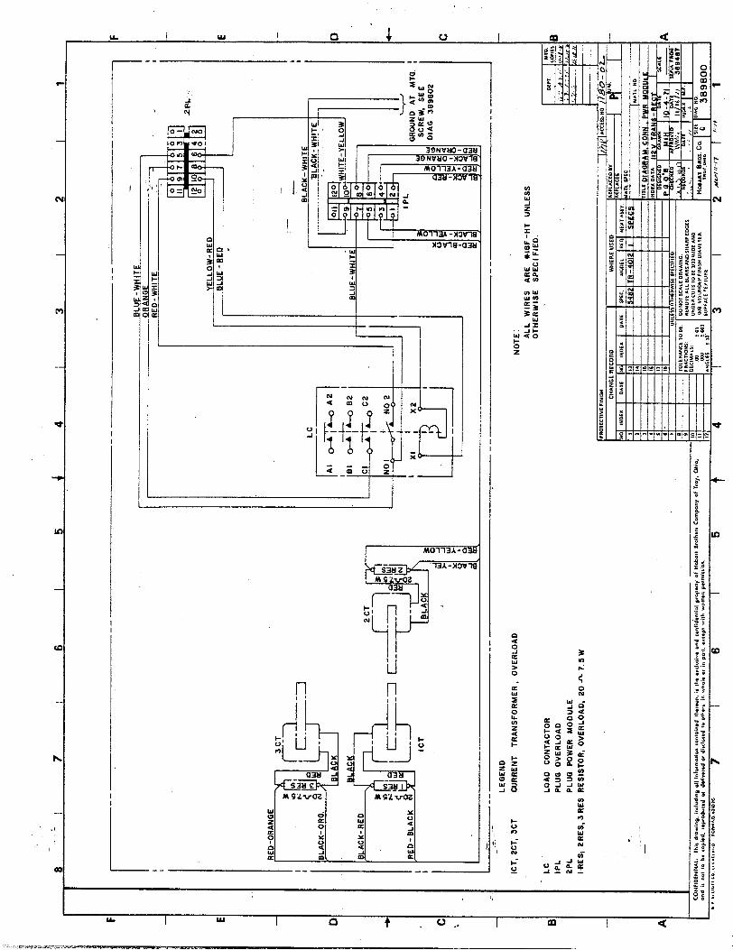
A complete set of connection diagrams is included in this section. When reconnecting wires to a component, use the connection diagrams to make certain that connections are made correctly.
Connections provided on the following pages are as follow, in the order that they appear:
DIAGRAM
T-R Connection Diagram Power Module Connection Diagram Control Panel Connection Diagram Overload Module Connection Diagram Overvoltage Module Connection Diagram
DIAGRAM NO. -
38 9802 389800 389801 387738A:.
'
389522d "1 ' I'
/ -
2-4
Page 2
Nov 30/77

. -
--
._- -
.- ~
_ ~...
-. -
. . ..
_ --.
-_..-
- . .._
.....-
...--
.-- -- .
.--.
-...-
. ._
.. ,- .
.._._
___.
.___
_ --
. .._ --
1 I,-
‘-.--
TT
T!
_ -_
-..-
- __
__
___
r --
C
NJi
it C
ON
NE
CT
CO
UP
LE
R
TE
RM
INA
L.
LE
GE
ND
+
NO
TE
.
lfl.2
S F
AN
. 3
PH
AS
E
ICT
, ZC
T,
XT
.
CU
RR
EN
T T
RA
NS
FO
RM
ER
, O
VE
RL
OA
D
OU
TPU
T T
ER
MIN
AL
S
AL
L
WIR
ES
eI
8F
-HT
U
NLE
SS
O
THER
WIS
E SP
ECIF
IED.
LC
L
OA
D
CO
NT
AC
TO
R
ov
$%JE
RV
OL
TA
GE
0O
AR
D
IPL
P
LU
G,
OV
ER
LO
AD
2PL
--
Pcu
i. P
OW
ER
M
OD
UL
E
3PL
. 4P
L
PL
UG
. C
ON
TR
OL
P
AN
EL
IRE
C
RE
CT
IFIE
R,
OU
TPU
T
TI
lRA
NS
FO
RM
ER
I 10
1..
ZT
GL
T
HE
RM
AL
O
VE
RL
OA
D
RE
LA
Y
-11.
111*
1” ~.
~#s.
ll*I~
. ,,
.I. ,
>,, .I
I ,,.
.. Y
, ,.
,h .
.‘I” ,
,., “
,dL
IIII..
II”I
,,.,..
. I,
.I 1y
I‘<’ .
I”0 ,
.., S
W.,“
. , ..I
CL
, CA
,,- *,“A
,% ,“a w
. I# .
e ,.,. d
. ..“
.d.,,
” _
--_
--.-
. ._
.-_
. -
___.
_ -,
-.-.
-_-.
_-
-.-.
--
_ _.
.. ---
___
-.yr
-

_ __, - . _ - . , .-._-.
* --
-.
j 7
6 I
5 4
4 I
3 I
2 I
1
RED-
ORA
NGE
d
NO
! I
L
!
. N
O2
,
OIA
G
3898
02
GL
UE
-WH
ITE
r B
LA
CK
- W
HIT
E
I
BL
AC
K-
WH
ITE
_ -n
- --
--
--
--
--
- -,
= .
:-
LE
GE
ND
ICT
. 2C
T,
SC
T
CU
RR
EN
T T
RA
NS
F~~
~ER
, O
VE
RL
OA
D
NO
TE
:
AL
L
WIR
ES
A
RE
M
GF
-I-IT
U
NLE
SS
O
TH
ER
WIS
E
SP
EC
IFIE
D.
LC
L
OA
D
CO
NT
AC
TO
R
IPL
P
LU
G
OV
ER
LO
AD
PP
L
PL
UG
P
OW
ER
M
OD
UL
E
IRE
&
PR
ES
, 3
RE
S
RE
SIS
TO
R,
OV
ER
LO
AD
, 20
A
7.
5 W

.-_,
,’
(1 i”. I ”
.I
! 1, ”
’ I
i

LE
GE
ND
AM
ME
TE
R
CA
PA
CIT
OR
, 20
M
FD
. 15
0 W
VD
C
FU
SE
, 2A
.
GR
EE
N
IND
ICA
TIN
G
LIG
HT
. L
OA
D
ON
P
LU
G,
CO
NT
RO
L
PA
NE
L
FAC
ING
R
EA
R
OF
F
RO
NT
P
AN
EL
I--
_.
--
___
--
-
AM
ICA
p,
PC
AP
IFU
. %
FU
G
3PL
, 4P
L
PR
EC
-.
4R
ES
JRE
S
&--
B
LUE
-WH
ITE
i
RH
OR
AN
GE
-RE
D
--I
2 R
EC
l--
---1
.--
- R
EG
TIF
IER
. C
ON
TA
CT
OR
-‘
RE
SIS
TO
R;H
OL
D
CIR
CU
IT
200
n25
W
RE
SIS
TO
R,
VO
LT
AG
E
DIV
IDE
R
250n
IOD
W
-.--
.
RH
EO
ST
AT
, I7
SJ-
i 35
W
S
WIT
CH
. C
ON
TA
CT
OR
S
WIT
CH
, IL
LUM
INA
TIN
G
LIG
HT
VO
LT
ME
TE
R
WH
ITE
IL
LUM
INA
TIN
G
LIG
HT
WH
ITE
-RE
D
ICA
P
IRA
NG
E-R
ED
--
--
/HIT
E-
RE
D
L
IFU
2A
2FU
2A
NO
TE
: N
OT
E: A
LL
W
IRE
S
AR
E
bI8
F-H
T
AL
L
WIR
ES
A
RE
b
I8F
-HT
UN
LES
S
OT
HE
RW
ISE
S
PE
CIF
IED
. U
NLE
SS
O
TH
ER
WIS
E
SP
EC
IFIE
D.
DW
T.
,g,:
D
WT
. ,g
,:
.-
./p
.-
./p
+-‘:
y-’
: r’
+-
‘:y-
’ :
r’
MA
KE
W
IRE
H
AR
NE
SS
T
O
3PL
A
ND
4P
L
MA
KE
W
IRE
H
AR
NE
SS
T
O
3PL
A
ND
4P
L
3‘
3‘
7’
LO
NG
, F
RO
M
THIS
P
OIN
T O
N
PA
NE
L
7’
LO
NG
, F
RO
M
THIS
P
OIN
T O
N
PA
NE
L
I I 3P
L
<RE
D-
K’:i
ITE
4P
L
WH
ITE
-YE
LL
OW


3lA
1 I
.j-
._
I : I-
- I ..--
-3 I
;$-
--
* 3-.-
- 3 I
,. T
’ -
, I_
--
1:
-f
.l- :
j-
-.
I
~II
zILz_
w
-m4r
s ,O
WU
-I
w-,l
Nw
-lo
W-,o
tW-1
. tm
7464
w
135-
ta
zG---
-- w
-l12a
7-5
HO
BA
RT
BR
OTH
ERS
CO
. TA
OY,
OH
IO
4537
3 U
s.4
T,TL
E Lj
CIAR
D . O
Vl=
r’a
511O
RT
CIRC
UIT
AY,
3577
384


RS 470n i I
02 b"--- -
RIO l5OA
LEGEND
CAPAClTOR 1.5/35 CAPACITOR 50/25 DIODE POTENTIOMETER 1K OHM, l/2 WA1 TRANSISTOR 2N-3903 TRANSISTOR ZN-3904 TRANSISTOR PROGRAMMABLE UNIJ- RESISTOR 330 OHM, 3-l/4 WATT RESISTOR 1200 OHM, l/2 WATT RESISTOR 4700 OHM, l/2 WATT RESISTOR 5600 OHM, l/2 WATT RESISTOR 22K OHM, l/2 WATT RESISTOR IOK OHM, l/2 WATT RESISTOR 270 OHM, l/2 WATT RESISTOR 470 OHM, l/2 WATT RESISTOR 150 OHM, l/2 WATT RELAY ZENER 22 VOLT
'T
*2N-
!
) ‘!
c
-6027
! / -1

I
.I
_
_ . _. .c_ .-
1. General
( 2.
3.
4.
i
_
1; c
_
CHAPTER 3. ILLUSTRATED PARTS LIST -
SECTION 1. INTRODUCTION
.
T&z Illustrated Parts List ideqtifle&‘describes. and illustrates main assemblies, subassemblies, and detail parts of
the iransformer-Rectifiers, manufactured by Hobart Brothers Company, Power Systems Division, Troy, Ohio
45373, and identified as Part Numbers 482085A-2 and-482085A-5.. \ _ _
Purpose
The purpose of this list is to provide parts identification and descriptive information to maintenance and provision-
ing personnel for use in provisioning, requisitioning, purchasing, storing, and issuing of spare parts.
Arrangement
Chapter 3 is arranged as follows:
Section 1 - Introduction
Section 2 - Manufacturer’s Codes
Section 3 - Parts List
Section 4 - Numerical Index
Exolanation of Parts List
A. Contents
The parts list contains a breakdown of the equipment into assemblies, subassemblies, and detail parts. All parts I
of the equipment are listed except:
(1) Standard hardware items (attaching parts) such as nuts, screws, washers, etc., which are available com- mercially.
(2) Bulk items such as wire, cable, sleeving, tubing, etc., which are also commercially available.
(3) Permanently attached parts which lose their identity by being welded, soldered, riveted, etc., to other
parts, weldments, or assemblies.
Parts List Form
This form is divided into five columns. Beginning at the left side of the form and proceeding to the right,
columns are identified as foiiows:
(1) FIGURE ITEM NO. Column
This column lists the figure number of the illustration applicable to a particular parts list and also
identifies each part in the list by an item number. These item numbers also appear on the’illustration.
Each item number on an illustration is connected to the part to which it pertains by a leader line. Thus
the figure and item numbering system ties the parts list to the illustration and vice versa. The figure and
index numbers are also used in the numerical index to assist theuser in finding the illustration pf a part
when the part number is known. I ‘1, ’ 1, .- . _
-. - . -.:-.--- -_.- _-.- --.a _-- - . __ 1.. -_ _ ---.--. -- ‘.
1 Nov 30177 ,_ - 3-l
Page 1

.,. ..,
I I
TM-598
;;
I
(2) HOBAR’T PART NUMBER Column
ALL part numbers appearing in this column are Hobart numbers. In all instances where the part is a
1 purchased item the vendor’s identifying five-digit code and his part number will appear in the NOMEN-
, / ‘I,iI ,, :CLATURE column. Vendq(rT p&s which are modified by Hobart will be identified as such in the NO-
‘MENCLATURE column. In case Hobart does not have an identifying part number for a purchased part,
the HOBART PART NUMBER column will reflect No Number and the vendor’s number will be shown
in the NOMENCLATUREcolumn. Parts manufactured by Hobart reflect no vendor code or part num-
ber in the NOMENCLATURE column.
(3) NOMENCLATURE Column
The item identifying name appears in this column. The indenture method is used to indicate item re-
lationship. Thus, components of an assembly are listed directly below the assembly and indented one
space. Vendor codes and part numbers for purchased parts are shown in this column. Hobart modifica-
tion to vendor items,is also noted in this column. ._ .- -
(4) EFF (Effective) Column ,
This column is used to indicate the applicability of parts to different models of equipment. When more than one model of equipment is covered by a parts list, there are some parts which are used on only one
model. This column is used for insertion of a code letter A, B, etc., to indicate these parts and to identify i
the particular model they are used on..Uncoded parts are used on all units. Parts in this list are coded as follows:
I
Parts coded A are used on 482085A.2 only.
Parts coded B are used on 482085A-5 only.
(5) UNITS PER ASSEMBLY Column
f This column indicates the quantity of parts required for an assembly or subassembly in which the part
appears. This column does not necessarily reflect the total used in the complete end item.
‘..
i 3:1
Page 2
Nov 3on7

I TM-596
;; - ._ __ . .- _ -i
SECTION 2. MANUFACTURER’S CODES
‘. \
1. Explanation of Manufacturer’s (Vendor) Code List . ‘.
The lollowing list is a compilation of, vendor codes with names and addresses for suppliers of purchased parts
&tt&!in this publication. The cod Q
I
s are in accordance with the Federal Supply Codes for Manufacturer’s Catalog- ’
ing Handbook H4-1, and are arranged in numerical order. Vendor codes are inserted in the nomenclature column ;
of the parts list directly following the item name and description. In case a manufacturer does not have a vendor
code,‘the full name of the manufacturer will be listed in the nomenclature column. / .I:
1.
CODE VENDOR’S NAME AND ADDRESS
04009 Arrow-Hart & Hedgeman Eiectric Company
103 Hawthorne Street ’
Hartford, Connecticut 06106
08106 . Lamp Industry For Use With Industry
Designations and Abbreviations for Lamps
13445 ColeHersee Company
20 Old Coiony Avenue Boston, Massachusetts 02127
14101 Sprague Electric Company
300 W. National
Vandalia, Ohio 45377
i 4859 Metals & Controls, Inc.
Control Products Group
300 North Main
Versailles, Kentucky 40383
27193 Cutler-Hammer, Inc.
Specialty Products Division
4201 N. 27th Street
Milwaukee, Wisconsin 53216
44655 Ohmite Manufacturing Company
3601 W. Howard Street
Skokie, Illinois 60076
60741 Triplett Electrical Instrument Company
Harmon Road
Bluffton, Ohio
’ 71400 Bussman Manufacturing Division of ;
McGraw-Edison Company
2536 W. University Street ,’ St. Louis, Missouri 63017
.I ! .’
;
I ‘!, :’ i’
L j ,;
..-.- -- - _ __,_ - d .-- -. - _._ _ ._ . . .._ _ .- -- -
t Nov 30177 I; 3-2
Page 1

I m r 1 I 1
;; _..
I
CODE VENDOR’S NAME AND ADDRESS
72619
I ’ i/l
74063
a3774
aim
a91 10
90201
90763 United-Carr Inc.
4258 N. Cicero
Chicago, Illinois 60646
91929 Honeywell Inc.
92702
$2
Page 2
TM-596
3
~ I, ” ’
Dialight Corporation
60 Stewart Avenue
Brooklyn, New York 11237
I
Hartman Electrical Manufacturing Company
P. 0. Box a
Mansfield, Ohio 44901
Midwest Electric Products
2114 N. Arsenal Avenue Indianapolis, Indiana 46218
Genisco Technology Corporation
Illinois Division
9367 William Street
Rosemont, Illinois 60018
Amp Inc.
155 Park Street Elizabethtown, Pennsylvania 17022
Mallory Capacitor Company
3029 E. Washington Street
P. 0. Box 372
Indianapolis, Indiana 46206
Building Controls & Components Group
Micro Switch Division
Chicago & Springs Street
Freeport, Illinois 61032
IMC Magnetics Corporation Eastern Division
570 Main Street
Westbury, New York 11591
! ;
I L!, ’ I’
3 Nov 30177 .-

.I
;;
I SECTION 3. PARTS LIST
1. Exolanation of Parts List Arranaement
TM-598
The pa@ list is arranged so that the illustration will appear on a left-hand page and the applicable parts list will
appear on the opposite right-hand p/age. Unless the list is unusually long, the user will be able to look at the illustra-
tion and read the parts list without turning a page.
t Nov 30177
1 [
I ‘!, ’ I
3-3
Page 1

TM-598
. .I
Transformer-Rectifier Assembly
Figure 1
! ’ /
I ‘!, L I’
3-b
Page 2
Nov 30177 -- !,

FIGURE ’
ITEM NO.
l-
I’ I ’ 6”)
1
( 2
3 4
- 5
6
7
a 9 10
.i -11
- <&- .I$
- 13
1’4
15
16
17
18 19
20
21
22
23
24
25 26
> 27 - 28
- 29 4015644
- 30 401565-l - ‘31 401566-l - 32 401563-3
- 33 430278
34 482814
35 389426
;;
HOeART
PART’NO.
4a2085A-2
4a2085A-5
389410
389254
389229
389226
389225
389251
389255
aRT-336
389333
W-10931-3
403692
389530
389256 aRT-336
389333
W-l 0933-3
403692
389262
389249
6FW-3167
389779
389260
389336
389503
389522
401556
389466
w-10051-10
389517
389445
389443
389444 389331
401563-4
NOMENCLATURE
1234567
TR+NSFORMER-RECTIFIER ASSEMBLY, 112 VOLT,
JDC A 1
’ TRANSFORMER-RECTIFIER ASSEMBLY, 112 VOLT,
DC WliH 24-VOLT POWER SUPPLY B 1
I .TOP 1
TM-598
. HEAT SINK ASSEMBLY
. . BRACKET, HEAT SINK
. . ,BUS BAR, ALUMINUM
. . BUS BAR, ALUMINUM
. . INSULATOR, BUS BAR
. . HEAT SINK ASSEMBLY, POSITIVE
. . . THERMOSTAT Vl4859, Type 204OOL
. . . BRACKET, THERMOSTAT
. . . DIODE, SILICON, 275 A., POSITIVE BASE
. * . FAN, HEAT SINK V92702, Model BT220 6F-O-1
. . . HEAT SINK, ALUMINUM
. . HEAT SINK ASSEMBLY, NEGATIVE
. . . THERMOSTAT Vl4859, Type 204OOL
. * . BRACKET, THERMOSTAT
. . . DIODE, SILICON, 275 A., NEGATIVE BASE
. . . FAN, HEAT SINK V92702, Model BT-220 6F&1
HEAT SINK, ALUMINUM
: I SUPPORT, HEAT SINK . SPACER
. TRANSFORMER ASSEMBLY’
. . TRANSFORMER ASSEMBLY, 112 VOLT
. . . EYE, LIFTING
. . . BRACKET, TRANSFORMER
. OVERVOLTAGE ASSEMBLY
. MOUNT, RUBBER
. BRACKET, RELAY
. CLAMP
. STRAP, GROUND
. BOARD ASSEMBLY, TERMINAL
BOARD, TERMINAL OUTPUT : : STRIP, INSULATING
.: BRACKET, TERMINAL BLOCK
. HOUSING, PIN CONNECTOR, MALE VaQllO, No. l-480288-0
. HOUSING, PIN CONNECTOR, FEMALE, VaQllO, No. l-480287-0
. TERMINAL PIN, va9i 10, NO. 61 i la-1 (STRIP)
. TERMINAL SOCKET VaQl 10, No. 61117-l (STRIP)
. HOUSING, PIN CONNECTOR, MALE VaQllO, 1-480286-1
. GROMMET
. POWER MODULE ASSEMBLY (For betails See Fig. 2)
. PLATE, TERMINAL, BUS BAR I’!,
1 4
2
2
2 1
1
1
6
1
1
1
1
1
6
1
1
2 4
1
1
2
4
1
3
1
3
1
1
1
1
1
1
1 19
10
1
1 1;
21
NOT ILLUSTRATED
Nov 30177 3-3
Page 3

,’
I ’ i”. I ”
3-p
Page 4
I ‘!,
TM-598
Nov 30177

FIGURE HOBART
ITEM NO. PART NO.
l-36 ’ - 371 ‘$j - 38
- 39
- 40 ; / 41
42
43
44
45
46
47
48
49
50
51
389427.
400176-4
400830-8
401913-3
389535
16DA-1997-12
369556
A-896-1
389524
482135
A-897-1
389359
482801
389360
389275
389769
- 52 400480-12
53 481578 . POWER SUPPLY 24 VOLTS (For Details See Fig. 4)
NOT ILLUSTRATED
t Nov 30177
TM-598
NOMENCLATURE
1234567
; !NSULATOR, BUS BAR
1, . TERMINAL, RING . TERMINAL, RING
. TERMINAL, RING
,. . ROPE, SUPPORT, HINGED DOOR
. BUTTON, PLUG HOLE
. COVER ASSEMBLY, TERMINAL
. NAMEPLATE, POSITIVE
. NAMEPLATE
. CLAMP, CABLE
. NAMEPLATE, NEGATIVE
. PANEL ASSEMBLY, TERMINAL SIDE
. PANEL ASSEMBLY, REAR
. PANEL ASqEMBLY, SIDE
. BASE
. PANEL ASSEMBLY, CONTROL (For Details See Fig. 3)
. TERMINAL, RECEPTACLE, SERIES 250, VaQllO, LP41729
UN ITS
per EFF ASSY
1
1
1
6
1
2
1
1
1
1
1
1
1
1
1
1
1
B 1
3-3
Page 5

TM-596
Power Module Assembly
Figure 2
I ‘!, L I’
343
Page 6
Nov 3Ol77

.._.. ._ _d .- ._,. I ..__. ..___ _, _.._ -
FIGURE
ITEM NO.
2-
2 ’
3 4
1 5
6
7
-a 9
_ :
‘,; ,
HOBART PART NO.
462814
lCZ-148
402935-5
369321
404518
367738A
401556
40 1563-4
401565-l
482809
. . . -.. 2 ., . _
NOMENCLATURE
1234567
YODULE ASSEMBLY, POWER (For NHA See Fig. 1)
~ 1, . TRANSFORMEh, CURRENT Va6151, E-6170
. RESISTOR, 5 WATT, TYPE RH
I - BRACKET, MOUNTING RESISTOR
. CONTACTOR, V74063, B-301P
. BOARD, P.C. OVERLOAD
. MOUNT, RUBBER
. HOUSING, PIN CONNECTOR
. TERMINAL SOCKET va9i IO, NO. 61 i 18-i
. BRACKET ASSEMBLY, MODULE, POWER *
TM-598
UNITS
per EFF ASSY
REF 4
3 . 3
1
1
4
1
10
1
.I ! ;
NHA NEXT HIGHER ASSEMBLY .) b!, ’ :I
t - NOT ILLUSTRATED
Nov 30177 3-3
Page 7

25
.26
\
>
TM-598
:, ?; )
‘i.
t 33
Page a
Control Panel Assembly
Figure 3
I L!, ’ I
/ Nov 30/77 .-
!#
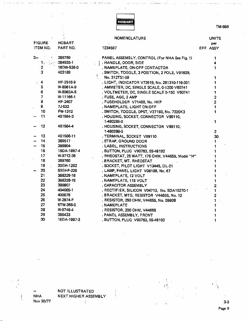
_ __ - _. . _
FIGURE HOBA’RT
ITEM NO. PART NO.
3-
‘I 2
3
’ 16DW-538-o
403189
/ 4 H F-25 1 a-9
5 W-8061 A-Q
6 W-8063A-5
7 W-l 1166-l
a H F-2407
9 75-532
10 FW-1312
- 11 401564-3
- 12 401564-4
- 13 401566-l 1
- 14 389517
- 15 389804
16 16DA-1997-4
17 W-9712-36
la 389760
19 30GH-1262
- 20 50GHP-206
21 368326-16
22 388328-l 5
23 389807
24 404065-l
25 400078
26 W-2974-F
27 5TW-356-O
28 W-9746-4
29 389433
30 16DA-1997-3
i NHA
NOT ILLUSTRATED
NEXT HIGHER ASSEMBLY
Nov 30177
__ _ - -.. .._ ,_ . ..__ ._._,
I I m I I
NOMENCLATURE
1234567
PANEL ASSEMBLY, CONTROL (For NHA See Fig. 1)
II ’ ‘AANDLE, DooR, SIDE
NAMEPLATE, ON-OFF CONTACTOR
: SWITCH, TOGGLE, 3 POSITION, 2 POLE, V91929,
’ No. 312TSl-59 . LIGHT, INDICATOR V72619, No. 261310-l 19-301
. AMMETER, DC, SINGLE SCALE, O-1200 V60741
. VOLTMETER, DC, SINGLE SCALE O-150 V60741
. FUSE, AGC, 2 AMP FUSEHOLDER V71400, No. HKP
: NAMEPLATE, LIGHT ON-OFF
. SWITCH, TOGGLE, DPST, V27193, No. 732OK3
. HOUSING, SOCKET, CONNECTOR VaQllO,
i-480285-o
. HOUSING, SOCKET, CONNECTOR VaQllO.
1-480288-o . TERMINAL, SOCKET VaQllO
. STRAP, GROUND DOOR
LABEL, INSTRUCTIONS
: BUTTON, PLUG V90763, SS48192
. RHEOSTAT, 25 WATT, 175 OHM, V44655, Model “H”
. BRACKET, MT. RHEOSTAT
. SOCKET, PILOT LIGHT V13445, DL-21
. LAMP, PANEL LIGHT voaioa, NO. 67
. NAMEPLATE, 12 VOLT
. NAMEPLATE, 115 VOLT
. CAPACITOR ASSEMBLY
. RECTIFIER, SILICON VO4713, No. SDAl0270-1
. BRACKET, MTG. RESISTOR V44655, No. 12
. RESISTOR, 250 OHM, V44655, No. 0960B
NAMEPLATE
: RESISTOR, 200 OHM, V44655
. PANEL ASSEMBLY, FRONT
. BUTTON, PLUG V90763, SS-48192
TM-598
UNITS
EFF I&Y
1
4
1
1
1
1
1
2
2
1 1
1
2
30 1
1
1
1
1
1
1
1
1
2
1
2
1
1
1
1
1
3-3
Page 9

TM-598
24-Volt Power Supply
Figure 4
i 3-3
Page 10 c
I ‘1, L :
I
Nov 30177

FIGURE
ITEM NO.
4 5
6 W-9026-2
t Nov 30177
4
HOBART
PART NO.
481578
481579
386781
402460-4
388720
400075-l
NOMENCLATURE
1234567
II POWiR SUPPLY, ,24 VOLT
. BRACKET, MOUNTING, TRANS. & FILTER
. TRANSFOtiMER WITH RECTIFIER, ASSEMBLY
1 . . CAPACITOR, TYPE MTA, 3 pF, 50 V DC, V90201, No. MTA 3D50
. FILTER, 24 V., ASSEMBLY
. . CAPACITOR, 20 vF, 150 V DC Vl4101,
No. TVA-1410 . . RESISTOR, 200 OHM, 10 WAlT V44655 ,
TM-598
---- 5
UNITS
. per :
EFF ASSY
B 1 .
B 1. ‘.
B 1
B 1 :
B 1
B 1
B 1
! !
I ‘!, , ’ I
3-3
Page 11


TM-598
;; SECTION 4. NUMERICAL INDEX ,
1. Explanation of Numerical Index
The purpose of this index is to assist the user in finding the illustration and description of a part when the part
numb$r is known. Part numbers are arranged in alpha-numerical sequence. Thus, any number beginning with the
lette& would be located at or near/the top of the index list. Likewise a part number 9 would be listed near the
end of the list and far below a part number 1000. The figure number and item number location of the part is
directly opposite the part. If the pati is used in more than one place, each location is listed commencing with the
first location the part is listed. ”
NUMERICAL INDEX
FIGURE AND PART NUMBER ITEM NUMBER ’
A-896-1
A-897-1
FW-1312
H F-2407
H F-25 1 B-7
w-10051-10
w-10931-3
W- 10933-3
W-11166-1 W-2974-E
W-8061 A-Q
w-8063A-5
W-9026-2
W-97 12-36 W-9746-4
lcf-148
16DA-1997-12
16D,A-1997-3
16DA-1997-4
16DA-42 10
16DW-538-O
30GH-1262
384935-l
38678 1
38773aA
’ 388328-i 5
3aa32B16
388720
389225
389226
’ 389229
389249
389251
389254
389255
389256
Nov 30/77
l-43
l-46
3-10
3-a
._ 34
l-23 .. r--~. i l-a
l-13
3-7
3-26
3-5
3-6
4-6
3-l 7 3-28
2-l
l-41
330
3-16
3-24
3-2
3-19
3-l
4-2
2-5
3-22 , 3-21
4-4
l-4
l-3
l-2 l-16
l-5
1-O 1,-o [
) $0 ’ I
Numerical Index
34
Page 1

. . . --..-. . .._ _.I.. .-. . . . . . . ..- --. ‘._ -.-.-^ __.,_.. ’ . .
TM-598
PARTNUMBER
389260 ' 389262 I ' '$4' ! :
389275
389321 389331
389333
389336
389359
389410
389426
389427
389433
389443
389444 j
389445
389466
389503
389517
389521
389522
389524
389530
369535 389556 389760
389769
389779
389804
400075
400078
400176-4
4oo4ao-12
400830-a 40155q
401563-3
401563-4
401564-3
401564-4
401565-l
401566-l
401566-11
NUMERICALINDEX (CONTINUED)
FIGUREAND
ITEMNUMBER
l-o
l-15
l-50
2-3 l-27
l-7
l-12
l-la
l-47
l-l
l-35
l-36
3-29
l-25
l-26
l-o
l-22
l-19
l-24
3-14
3-23
l-20
l-42
l-10
l-40
l-42 3-18
l-51
1-o
3-15
4-5
3-25 137
l-52
l-38
l-21
2-6
l-32
l-28
2-7
3-11
l-29
3-12
l-30
2-a
l-31, !:
3-13 I '1, L I’
Numerical Index
314
Page 2
.
'Nov30177

_ _ . _
PART NUMBER
401913-3
4024&q
402935-5
403189
403692,
404518
481578
481579
482085A-2
482085A-5
482135
482801
482809
482814
5TW-356-O
50GHP-206
6FW-3167
7J-532
aRT-336
w .:. - I 1
NUMERICAL INDEX (CONTINUED)
FIGURE AND
ITEM NUMBER
!I,“’ l-39
4-3 2-2
3-3 1-9
l-4
2-4
l-53 4-O 4-l ’
l-o
l-o
l-45
l-48
2-Q
l-34
2-o
3-27
3-20
l-17
3-Q
l-6
l-11
TM-598
! !
) ‘! I ’ ‘I
i Nov 30177 Numerical Index / 3-4
Page 3

I ‘1, L