tm 55-1510-218-mtf - liberated manuals.com · maintenance test flight manual army model c-12c/d/f/u...
TRANSCRIPT

TM 55-1510-218-MTF
MAINTENANCE TESTFLIGHT MANUAL
ARMY MODELC-12C, C-12D, ANDC-12F AIRCRAFT
T h i s m a n u a l s u p e r s e d e s T M 5 5 - 1 5 1 0 - 2 1 8 - M T F ,1 0 O c t o b e r 1 9 8 4 , i n c l u d i n g a l l c h a n g e s .
HEADQUARTERS,DEPARTMENT OF THE ARMY
19 JUNE 1989


URGENT
TM 55-1510-218-MTF C1 CHANGE HEADQUARTERS NO. 1 DEPARTMENT OF THE ARMY
WASHINGTON, D.C., �� ������� 2009
MAINTENANCE TEST FLIGHT MANUAL
ARMY MODEL C-12C/D/F/U AIRCRAFT
NSN 1510-01-070-3661 NSN 1510-01-087-9129 NSN 1510-01-470-0220
DISTRIBUTION STATEMENT A: Approved for public release; distribution is limited. TM 55-1510-218-MTF, 19 June 1989 is changed as follows:
1. Remove and insert pages as indicated below. A vertical bar in the margin indicates new or changed text material. A miniature pointing hand indicates an illustration change. Remove pages Insert pages 2-57 through 2-60 2-57 through 2-60 2-63 through 2-66 2-63 through 2-66 5-9 and 5-10 5-9 and 5-10 2. Retain this sheet in front of manual for reference purposes.

TM 55-1510-218-MTF C1 3. This change incorporates SAFETY OF FLIGHT, OPERATIONAL, RCS CSGLD-1860 (R1), C-12 SERIES AIRCRAFT, STALL WARNING SYSTEM TEST, C-12-04-01 MSG DTG 131200Z APR 04.
By Order of the Secretary of the Army:
GEORGE W. CASEY, JR. General, United States Army
Chief of Staff
0925305
JOYCE E. MORROW Administrative Assistant to the
Secretary of the Army
Official:
Distribution:
To be distributed in accordance with the�initial distributionnumber (IDN) 310006,�requirements for TM 55-1520-218-
���MTF.

TM 55-1510-218-MTF
A maintenance test flight is an exceptionallydemanding operation and requires a thor-ough flight readiness inspection (PRE-FLIGHT). The flight readiness inspection isprescribed in TM 55-1510-218-10 operator’smanual and must be completed prior to eachmaintenance test flight. Emergency proce-dures are found in the applicable -10 orchecklist (-CL) and are not duplicated in thispublication. Prior to each maintenance testflight, the pilot will contact maintenance/quality control personnel to determine themaintenance that has been performed. Thismanual should be used only by qualifiedmaintenance test flight pilots as required inAR 95-1.
i

TM 55-1510-218-MTF
TABLE OF CONTENTS
REPORTING ERRORSAND RECOMMENDING IMPROVEMENTS
You can help improve this manual. If you find anymistakes or if you know of a way to improve the pro-cedures, please let us know. Mail your letter, DAForm 2028 (Recommended Changes to Publicationsand Blank Forms), or DA Form 2028-2 located in theback of the applicable Aircraft Operator’s Manual(when using the 2028-2 from the Operator’s Manual,ensure the publication number and title reflect thisMTF) direct to Commander, US Army Aviation Sys-tems Command, ATTN: AMSAV - MMD, 4300 Good-fellow Blvd., St. Louis, MO 63120. A reply will befurnished tO you.
S e c t i o n
I Int roduct ion . . . . . . . . .
II Maintance Test Flight Checklist . . . . .
Prior to Maintance Test Flight . . . . . .
I n t e r i o r C h e c k . . . . . . . . .
B e f o r e S t a r t i n g E n g i n e s . . . . .
First Engine Start(Battery Start) . . . . .
Second Engine Start (Battery Start) . . . . . .
F i r s t E n g i n e S t a r t ( G P U S t a r t ) . . .
Second Engine Start (GPU Start). . . . . .
Before Taxiing . . . . . . . . . . . . .
Taxiing . . . . . . . . . . . . . . . . .
Engine Runup . . . . . . . . . . . . .
Before Takeoff . . . . . . . . . . . . .
Line Up . . . . . . . . . . . . .
Dur ing Takeof f . . . . . . . . . .
A f t e r T a k e o f f . . . . . . . . . .
ii
P a g e
1-1
2-1
2-1
2-6
2-8
2-18
2-19
2-22
2-24
2-25
2-36
2-37
2 - 4 6
2-47
2-47
2-48

TM 55-1510-218-MTF
TABLE OF CONTENTS (CONT)
During Climb . . . . . . . . . . . . . . . . 2-49
Cruise . . . . . . . . . . . . . . . . . . . 2-52
Low Speed Systems Check . . . . . . . . 2-57
Descent and Low Level Cruise . . . . . . . . 2-69
Descent . . . . . . . . . . . . . . . . 2-71
Before Landing . . . . . . . . . . . . . . . . . . . . 2-71
Landing . . . . . . . . 2-71
Go Around . . . . . . . . . . . . . . 2-72
After Landing . . . . . . . . . . . 2-73
Engine Shutdown . . . . . . . . . . 2-73
Before Leaving Aircraft . . . . . . . . . 2-75
III Troubleshooting . . . . . . . . . . 3-1
Troubleshooting Guide A - Starting . . . . 3-1
Troubleshooting Guide B - Instruments . . . 3-4
Troubleshooting Guide C - Electrical . . . . . 3-6
Troubleshooting Guide D - Caution Panel . . . . . 3-17. . . . . . . . . . . . . . . . . . . .
Troubleshooting Guide E - Power Plant. . . . . . . . . . . . . . . . . . . . . 3-18
Troubleshooting Guide F- Propellers . . . . . . 3-24
Troubleshooting Guide G - Hydraulic . . . . . . . 3-27
Troubleshooting Guide H - Flights . . . . . . . . . 3-28Controls . . . . . . . . . . . . . . . . . . .
Troubleshooting Guide I - Not Applicable . . . . . . . . . . . . . . . . . . 3-29
Troubleshooting Guide J - Vibrations . . . . 3-30
Troubleshooting Guide K - 3-31Communications/Navigation Equipment. . . . . . . . . . . . . . .
IV Special Procedures . . . . . . . . . . . . . 4-1
Charts and Forms . . . . . . . . . . . . . . . . . . 5-1
i i i /( iv blank)


TM 55-1510-218-MTF
SECTION I. INTRODUCTION
1 . Purpose. The purpose of this manual is to providecomplete instructions for performing a maintenancetest flight of C-12C, C-12D, and C-12F aircraft. Forthe specific conditions which require a general or limit-ed maintenance test flight, refer to applicable FAR’sand manufacturer’s maintenance manuals.
2. Definitions.
a. Maintenance Test FLIGHT. A functional testflight for which the primary purpose is to determinewhether the airframe, powerplant, accessories, and oth-er equipment are functioning in accordance with pre-determined requirements while subjected to the intend-ed environment.
b. Warnings, Cautions, and Notes. Warnings,Cautions, and Notes are used to emphasize importantand critical instructions and are used for the followingconditions:
An operating procedure, practice, etc.,which, if not correctly followed, could resultin personal injury or loss of Iife.
An operating procedure, practice, etc.,which, if not strictly observed, will result indamage to or destruction of equipment.
1-1
TM 55-1510-218-MTF
NOTE
An operating procedure, condition, etc.,which is essential to highlight.
3 . General Information.
a. This manual covers only maintenance testflight of C-12C, C-12D, and C-12F aircraft and in noway supersedes any information contained in TM 55-1510-218-10 or -CL, but is to be used in conjunctionwith the -10 or -CL. For the purpose of maintenancetest flights only, this manual satisfies all the require-ments of the -CL from Interior Check through EngineShutdown.
b. Crew requirements wiII be as specified inTM 55-1510-218-10.
4. Special Instructions.
a. Cargo and Passengers. Cargo and passengersare prohibited on maintenance test flights.
b. Forms and Records. Forms and records willbe checked prior to the maintenance test flight to de-termine what maintenance has been performed and thetype of maintenance test flight required (i.e general orIimited).
c. Configuration. The configuration of the air-craft should be determined prior to each maintenancetest flight in order to determine performance parame-ters.
d. Post Test Flight Inspection. A thorough visu-al inspection will be performed to the extent necessaryto ensure that deficiencies or short-comings that mayhave developed as a result of the maintenance testflight are detected.
e. Reference. When a maintenance test flight isrequired to ensure proper operation of a specific sys-tem(s), refer to the applicable maintenance manual forthe Iimits of that system.
f. Asterisked Checks. An asterisk (*) prior to acheck requires that the test flight check sheet be anno-
1-2

T M 5 5 - 1 5 1 0 - 2 1 8 - M T F
tated with a specific reading. Also a check ( ü ) for sat-isfactory performance, or a (X) for problem detectedwiII be recorded and a short statement entered in theremarks block of the check sheet.
g. An (O) prior to a check indicates a require-ment if the equipment is installed.
h. Maintenance Test Flight Check Sheet. Thecheck sheet contained in Section V will be used for alltest flights. When a test flight is performed to deter-mine if specific equipment or systems are operatingproperly, completion of only that portion of the main-tenance test flight check sheet applicable to the specificequipment or systems being tested is required. The air-craft test flight check sheets may be locally reproduced.Continuation sheets may be used when necessary.ltems that prove to be unsatisfactory during the testflight and require corrective action, shall be listed inthe remarks block during flight and transferred to DAForm 2408-13 immediately after termination of theflight. The sheet will be attached to the DA Form2408-13 upon completion. After accumulation of twoor more sheets, the data should be reviewed to deter-mine if trends are developing.
i. Free Air Temperature (FAT) and Outside Air Temperature (OAT). For the purposes of this manual,free air temperature (FAT) is to be considered thesame as outside air temperature (OAT).
1-3/(1-4blank)


TM 55-1510-218-MTF
SECTION II. MAINTENANCE TESTFLIGHT CHECKLIST
General. This section contains the maintenance testflight requirements peculiar to Army Models C-12C, C-12D, and C-12F aircraft. The requirements containedherein are established to ensure a thorough inspectionof the aircraft before fl ight, during fl ight and uponcompletion of the maintenance test fl ight. The rightside of the checklist (troubleshooting reference) is crossindexed to the troubleshooting guides contained in Sec-tion III. A dash between references means “through”;and a comma means “and”. The references list the pos-sible abnormal conditions, indications or malfunctionswhich could be encountered while performing the pro-c e d u r e .
PROCEDURE TROUBLESHOOTING
REFERENCE
PRIOR TO MAINTENANCE TESTFLIGHT
*1. Forms and records - Check.
*2. Weight and balance - Maintenancetest flights shall be flown with bal-last i f required to remain withinweight and center-of-gravity limits.Refer to individual charts in Sec-tion V for required aircraft weightat time of test.
* 3 . Thorough flight readiness inspec-t i on i n acco rdance w i th t he re -qui rements conta ined in TM 55-1510-218-10 - Performed.
4. Special preflight checks:
a. Keylock switch - On
b. Battery switch - On. C7-11
2-1

TM 55-1510-218-MTF
PROCEDURE TROUBLESHOOTINGREFERENCE
PRIOR TO MAINTENANCE TESTFLIGHT (CONT)
*c. Interior, exterior, and annunci- C45ator lights - Check.
*d. Fuel control panel- Check thes tandby pumps and f i r ewa l lvalves as follows to ensure thatthey are powered through theessential bus:
(1) Battery switch - OFF.
( 2 ) S t a n d b y p u m p c i r c u i tbreakers (left and right) -P u l l .
C4
(3) Firewall shutoff valve cir-cuit breakers (Ieft andright) - Pull.
(4) F i r e w a l l s h u t o f f v a l v eswitches - Close, (listen foroperation).
(5) Standby pump swi tches - ON, then listen for opera-tion.
(6) Battery switch - ON. Check#1 FUEL PRESS and #2FUEL PRESS annunciatorIights illuminated.
(7) F i r e w a l l s h u t o f f v a l v eswitches - OPEN Check #1FUEL PRESS and #2FUEL PRESS annunciatorI ights ext inguished.
(8) Standby pump switches -OFF.
2-2
TM 55-1510-218-MTF
PROCEDURE TROUBLESHOOTINGREFERENCE
( 9 ) S t a n d b y p u m p c i r c u i tbreakers (Ieft and right) -In.
(10) Firewall shutoff valve cir-c u i t b r e a k e r s ( I e f t a n dright) - In.
(11) Crossfeed valve switch -Set alternately to Ieft andr ight system. Check thatF U E L C R O S S F E E D a n -nunciator light illuminates,and that the #1 and #2FUEL PRESS annunciatorlights are extinguished.
(12) Crossfeed valve switch -OFF.
*(13) Fuel quant i ty indicators - C46, B6-8Check as follows:
(a) Fuel quantity indicatorselector switch -M A I N .
(b ) Fue l quan t i t y i nd i ca -tors - Compare indica-tion. With full fuelt a n k s , l e f t a n d r i g h tfuel quantity indicatorsmust indicate within 82pounds of each otherwith fuel quantity indi-cator selector switch setto MAIN.
(c) Fuel quantity indicatorselector switch - AUX-IL IARY.
(d ) Fue l quan t i t y i nd i ca -tors - Compare indi-
2-3

TM 55-1510-218-MTF
PROCEDURE TROUBLESHOOTINGREFERENCE
PRIOR TO MAINTENANCE TESTFLIGHT (CONT)
ca t i on . W i th f u l l f ue ltanks , I e f t and r i gh tfuel quantity indicatorsmust indicate within 35pounds of each otherwith fuel quantity indi-cator seclector switch setto AUXILIARY.
*e Pitot tubes (2), stall warningvane, and heated fuel vents (2)- Check as follows:
(1) Stall warning heat switch -O N .
(2) Pilot heat switches - ON.
(3) Fuel vent heat switches (2)- O N .
(4) Left wing heated fuel vent- Check by feel for heat,and condition.
(5) Stall warning vane - Checkby feel for heat, and condi-tion.
(6) Left pilot tube - Check byfee l f o r hea t , cond i t i on ,and free of obstructions.
C39
(7) Right pilot tube - Check byfeel for heat, condition,and free of obstructions.
C30
(8) Right wing heated fuel vent-Check by fee l f o r hea t ,and condi t ion.
2-4

TM 55-1510-218-MTF
PROCEDURE TROUBLESHOOTINGREFERENCE
(9) Stall warning heat switch -OFF.
(10) Pi lot heat swi tches (2) - OFF.
(11) Heated fuel vent swi tches(2 ) - OFF .
*f. Flaps - Check in full down andful l up posi t ions.
*g. Battery switch - OFF.
*h. Seat belts - Check for security,a n d p r o p e r c o n d i t i o n s .
*i. Emergency equipment - Checkt h a t a l l r e q u i r e d e m e r g e n c yequipment is available and thatfire extinguishers and first-aid
k i t s have cu r ren t i nspec t iond a t e s .
*j. Check all interior and exterior
placards and markings.
*k. Trim tab travel and direction -Check. Trim tabs shall be oper-ated through the full range oftravel, not ing any excessive friction or binding. Tab direc-tion and neutral position willbe checked at the control andthe su r face .
*I. FIight controls - Check opera-tion and direction. Checkmovement of control surfacesfor direction with movement ofcockpit controls. Check for anyabnormal f r ic t ion or obstruc-tions through full range of trav-e l .
2-5

TM 55-1510-218-MTF
PROCEDURE TROUBLESH00TINGREFERENCE
INTERIOR CHECK1. Cargo/loose equipment - Check se-
cure.
*2. Cabin/cargo doors - Test and lock:
a. Cabin door (C-12C) - Checkclosed and Iatched by the fol-Iowing:
(1) Safety arm - Check in posi-tion around diaphragmplunger (lift door step).
(2) Safety arm and diaphragmplunger - Check position(lift door step).
(3) Index marks (green) on ro-tary cam locks (6) - Checkaligned with pointers.
( 4 ) D o o r o p e n annunciatorlight - Check for appropri-ate indication.
b. Cabin door (C-12D and C-12F)- Check closed and latched bythe following:
(1) Safety arm - Check in posi-tion around diaphragmplunger (lift door step).
(2) Safety arm and diaphragmplunger - Check position(Iift door step).
(3) Scribe Iines on rotary camlocks (6) - Check alignedwith black Iines on uphol-stery.
( 4 ) D o o r o p e n a n n u n c i a t o rlight - Check for appropri-ate indication.
2-6

TM 55-1510-218-MTF
PROCEDURE TROUBLESHOOTINGREFERENCE
c. Cargo door - Check closed andlatched by the following:
( 1 ) U p p e r h a n d l e - C h e c kclosed and latched. (Ob-serve through cargo doorlatch handle access coverwindow.)
(2) Scribe lines on rotary camlocks (4) - Check alignedwith green line on gas cyl-inder and black line on theupholstery.
(3) Lower p in latch handle -Check closed and latched.(Obse rve th rough ca rgodoor lower latch handle ac-cess cover window.)
(4) Carrier rod - Check orangeindicator a l igned wi th or-ange stripe on carrier rod.(Observe through window,aft lower corner.)
d. Battery switch - OFF.
e. Cargo door - Check closed andlatched.
f. Cabin door - Close but leaveunlatched. Check CABINDOOR annunciator l ight i l lu-minated.
g . Cab in doo r - Open . CheckC A B I N D O O R a n n u n c i a t o rlight extinguished.
h . Ba t te ry sw i t ch - ON. CheckC A B I N D O O R a n n u n c i a t o rlight illuminated.
2-7

TM 55-1510-218-MTF
PROCEDURE TROUBLESHOOTINGREFERENCE
INTERIOR CHECK (CONT)i. Cabin door - Close and latch.
Check CABIN DOOR annunci-ator I ight ext inguished.
NOTE
The above procedures check both cargo ancabin door security provisions.
*3. Emergency exit - Check secure andkey removed.
4. Crew briefing - As required.
BEFORE STARTING ENGINES1. Seats, pedals, belts, harnesses - Ad-
just.
2. Flight controls - Check for free andcorrect movements.
*3. Park ing brake - Check. Conf i rmthat brakes are set by applying ad-ditional toe pressure.
*4. Oxygen system - Set (PULL ONCREW READY/SYS READY, C -12C and C-12D, prior to serialnumber 8 4 - 2 4 3 7 5 , o r SYSREADY, C-12D after serial num-ber 84-24375 and C-12F).
5. Circuit breakers - Check in.
6. Overhead control panel - Check. C45
a. Light dimming controls - As re-quired.
b. Cabin temperature mode selec-tor switch (C-12C, C-12D and
2-8
TM 55-1510-218-MTF
PROCEDURE TROUBLESHOOTINGREFERENCE
C-12F prior to serial number86-60084) - OFF.
c. Cabin air mode selector switch(C-12F after serial number 86-60084) - OFF.
d. Ice and rain switches - OFF.
e. Engine anti-ice switches - OFF.
f . Interior light switches - As re-quired.
g. Exterior light switches - As re-quired.
h. Master panel lights switch - Asrequired.
i. Inverted switches - OFF.
j. Avionics master power switch - O F F .
k. Environmental swi tches - Asrequired.
l . A u t o f e a t h e r s w i t c h - O F F .
m. #1 Engine start switches - OFF.
n. Master switch - OFF.
o. #2 engine start switches - OFF
7. Fuel panel switches - Check as fol-
lows:
a. Standby fuel pump switches -O F F .
b . Aux i l i a ry t rans fe r over r ide switches - AUTO.
c. Crossfeed switch - OFF.
*8. Magnetic compass - Check for flu-id, heading, and current deviationcard.
2-9
TM 55-1510-218-MTF
PROCEDURE TROUBLESHOOTINGREFERENCE E
BEFORE STARTING ENGINES (CONT)9. Clock and map light switches (C-
12C, C-12D, and C-12F prior to se-rial number 86-60084) - OFF.
12. Clocks (C-12F prior to serial num- ber 86-60084) - Set.
11. CIocks (C-12C, C-12D, and C-12Fprior to serial number 86-60084) -Wind and set.
10. Map light switches (C-12F prior to serial number 86-60084) - OFF.
Movement o f t he power l eve rs i n to RE-VERSE range whi le the engines are shutdown may result in bending and damage tocontro l l inkage.
13. Pedestal controls - Set as follows:
a. Power levers - IDLE. E 7
b. Propeller levers -HIGH RPM.
c. Condition levers - FUEL CUT-O F F .
d. Flap lever - UP.
e. Friction locks - Check and set.
14. Pedestal extension (C-12C and C-12D w i th se r ia l number p r i o r t o84-24375) - Check and set as fol-lows:
a. Avionics - Set as required.
2-10

TM 55-1510-218-MTF
PROCEDURE TROUBLESHOOTINGR E F E R E N C E
b. Rudder boost switch - ON.
c. Gear al ternate extension andratchet handle - Stowed.
15. Pedestal extension (C-12D with se-rial number after 84-24357 and C-12F) - Check and set as follows:
a. Avionics - Set as required.
b. Rudder boost switch - On.
c. Cabin pressurization switch -P R E S S .
d. Cabin controller - Set (field ele-
vat ion +500 feet) .
e. Rate control -Set (approxi- mately 1 o ’c lock post ion) .
f . Cabin pressur izat ion switch -P R E S S .
g. Gear alternate extension pumphandle - Stowed.
*16. Free air temperature gage - Checkcondition. Note current reading.
17. Pilots’ instrument panel (C-12C
and C-12D with serial number pri-or to 84-24375) .
a. VOR swi tch - No. 1.
b. Compass switch - No. 1.
c . MIC swi tch - HEADSET.
d . Gy ro sw i t ch - SLAVE.
*e. Pi lot ’s f l ight instruments -Check instrument for protec-tive glass, warning flags (10),and static readings.
2-11

T M 5 5 - 1 5 1 0 - 2 1 8 - M T F
P R O C E D U R E T R O U B L E S H O O T I N GREFERENCE
BEFORE STARTING ENGINES (CONT)f. Radar - OFF.
g. PROP SYN switch - OFF.
*h. Engine instruments - Check forprotective glass, range mark-ings, placards, and static read-i n g s .
1 8 . P i l o t s ’ i n s t r u m e n t p a n e l ( C - 1 2 Dwith ser ia l number af ter 84-24375and C-12F)- Check and set:
a. MIC switch - HEADSET.
b . C o m p a s s # 1 g y r o s w i t c h -SLAVE.
* c . P i l o t ’ s f l i g h t i n s t r u m e n t s -Check inst rument for protec-tive glass, warning flags, andstatic readings.
d . Rada r - OFF .
e . P R O P S Y N s w i t c h
*f . Engine inst ruments - Check forp r o t e c t i v e g l a s s , r a n g e m a r k -ings, placards, and static read-i n g s .
19. Cabin controller - Set (field eleva-t i on +500 fee t ) .
20. Rate control - Set (approximately 1
o ’ c l ock pos i t i on ) .
2 1 . C a b i n p r e s s u r i z a t i o n s w i t c h -P R E S S .
22. Copi lot ’s instrument panel (C-12Cand C-12D with serial numbers pri-o r t o 8 4 - 2 4 3 7 5 ) .
2 - 1 2

TM 55-1510-218-MTF
PROCEDURE TROUBLESHOOTINGREFERENCE
*a. Copi lot ’s f l ight instruments -Check instruments for protec-tive glass, warning flags (5),and static readings.
b . Cop i l o t ’ s compass sw i t ch -No. 2.
c. Copilot’s VOR switch - No.2.
d. Copilot’s microphone switch -HEADSET.
e. Copilot’s gyro switch - SLAVE.
23. Copilot’s instrument panel (C-12Dwith ser ia l numbers af ter to 84-24375 and C-12F).
*a. Copi lot ’s f l ight instruments -Check instruments for protec-tive glass, warning flags, andstat ic readings.
b. Copilot’s compass #2 switch -SLAVE.
c. Copilot’s microphone switch -HEADSET.
24. Subpanel (C-12C and (C-12D withserial number prior to 84-24375) -Check and set:
a. Fire protection test switch -OFF.
b. Landing, taxi, and recognitionlights - OFF.
c. Landing gear control switch -Recheck DN.
d. Pilot’s static air source - NOR-M A L .
2 -13

TM 55-1510-218-MTF
PROCEDURE TROUBLESHOOTINGREFERENCE E
BEFORE STARTING ENGINES (CONT)
NOTE
Do not use alternate static source duringtakeoff and landing except in an emergency.Pilot’s instruments will show a variation inairspeed and altitude.
25. Subpanel (C-12D after serial num-ber 84-24375 and C-12F) - Checkand set:
a. Landing, taxi, and recognitionIights - OFF.
b. Landing gear control switch -Recheck DN.
C . Pilot’s static air source- NOR-M A L .
NOTE
Do not use alternate static source duringtakeoff and landing except in an emergency.Pilot’s instruments will show a variation inairspeed and altitude.
26. Ice vane handles (#1 and #2) - In.
27. GPU - Connect as required. Check C-12external power annunciator light il-luminated.
28. Batter switch - ON.
*29 Annunciator panels (C-12C and C- D1-41 2 D p r i o r t o s e r i a l n u m b e r 8 4 -24375) - Test as follows:
a. Check illumination of theMASTER CAUT ION, MAS-
2 -14

TM 55-1510-218-MTF
PROCEDURE TROUBLESHOOTINGREFERENCE
T E R , W A R N I N G , N o . 1F U E L P R E S S , N o . 2 F U E LPRESS, L BL AIR FAIL, R BLAIR FAIL, INST AC warningIights and #1 DC GEN, #2 DCGEN, #1 INVERTER, #2 IN-V E R T E R a n d t h e # 1 N OFUEL XFR and #2 NO FUELXFR (if applicable) cautionlights.
b. Annunciator test switch - Pressand hold. Check that all lightsin bo th annunc ia to r pane l s ,FIRE PULL handle lights,marker beacon l ights, MAS-TER CAUTION and MASTERWARNING l i gh ts a re i l l um i -nated. Release switch andcheck tha t a l l l i gh ts excep tthose in step a. are extin-guished.
c. Master caution and masterwarning lights - Press and re-lease. Both lights should extin-g u i s h .
*30. Annunciator panels (C-12D af terser ia l number 84-24375 and C-12F) - Test as follows:
D1-4
a . C h e c k i l l u m i n a t i o n o f t h eM A S T E R C A U T I O N , M A S -T E R W A R N I N G , # 1 F U E LPRESS, #2 FUEL PRESS, LBL AIR FAIL, R BL AIRFAIL, and INST AC warningl i gh t s ; #1 DC GEN, #2 DC-GEN, #1 INVERTER, #2 IN-VERTER, #1 NO FUEL XFR,#2 NO FUEL XFR, CABIN
2 - 1 5
TM 55-1510-218-MTF
P R O C E D U R E T R O U B L E S H O O T I N GREFERENCE
BEFORE STARTING ENGINES (CONT)D O O R ( i f o p e n ) , a n d R E VNOT READY caution lights.
b. Annunciator test switch - Pressand hold. Check that all lightsin bo th annunc ia to r pane l s ,FIRE PULL handle lights,marker beacon lights, MAS-TER CAUTION and MASTERWARNING l i gh ts a re i l l um i -nated. Release switch andcheck that all lights exceptthose in step (a) are extin-g u i s h e d .
c. Master caution and masterwarning lights - Press and re-lease. Both lights should extin-guish.
*31. Stall and gear warning system - C29,40-Check as follows: 4 1
a. Stall and landing gear warningtest switch - Lift to STALLWARN TEST postion. Checkfor warning horn tone and V i -sually check for stall warningvane movement.
b. Stall and landing gear warninghorn test switch - Set to LDGGEAR WARN TEST position.Check for warning horn toneand that the red LDG GEARCONTR handle warning lights(2 ) i l l umina ted .
*32. Fire protection system (C-12C, C- C49-5112D, and C-12F aircraft prior to C-12F ser ia l number 86-60084) -Check as follows:
2 - 1 6

TM 55-1510-218-MTF
PROCEDURE TROUBLESHOOTINGREFERENCE
a . F I R E P R O T E C T I O N T E S Tswitch - Rotate switch counter-clockwise to check three DETRpositions. FIRE PULL handlesshould illuminate in each posi-t i o n . M A S T E R W A R N I N Gmust be reset in each position.
b . F I R E P R O T E C T I O N T E S Tswitch - Rotate switch counter-clockwise to check two EXT-G H p o s i t i o n s . S Q U I B O Klight, associated EXTGH DIS-CH cau t i on l i gh t , and MAS-T E R C A U T I O N L I G H Tshould illuminate in each posi-tion.
*33. Fire protection system (C-12F air-craft after serial number 86-60084)- Check as follows:
a . E N G I N E FIRE PROTEC-TION TEST switches - Holds w i t c h e s t o D E T p o s i t i o n ,check that FIRE PULL handlewarning lights, and MASTERWARNING l i gh ts i l l um ina te .
b . E N G I N E F I R E P R O T E C -TION TEST switches - Holds w i t c h e s t o E X T p o s i t i o n ,check that SQUIB OK annun-c i a t o r a n d M A S T E R W A R N -ING lights illuminate.
2 - 1 7
TM 55-1510-218-MTF
PROCEDURE TROUBLESHOOTINGREFERENCE
FIRST ENGINE START (BATTERYSTART)
1. Exter ior l ight switches - As re-quired.
2. Strobe beacon lights switch - Off.
3. Propeller - CIear.
4. Ignition and engine start switch -ON Propeller should begin to ro-tate and associated IGN ON lights h o u l d i l l u m i n a t e . A s s o c i a t e dFUEL PRESS l ight should ext in-gu i sh .
A1-8
If ignition does not occur within 10 secondsafter moving condition Iever to LOW IDLE,in i t ia te ENGINE CLEARING procedure. I ffor any reason a starting attempt is discon-tinued, the entire starting sequence must berepeated after allowing the engine to cometo a complete stop (1 minute minimum).
5. Condition lever (after N 1 RPM sta-b i l i z e s . 1 2 % m i n i m u m ) - L O WIDLE.
2 - 1 8

TM 55-1510-218-MTF
PROCEDURE TROUBLESHOOTINGREFERENCE
Monitor TGT to avoid a hot start. If thereis a rapid rise in TGT, be prepared to abortthe start before limits are exceeded. Duringstart ing, the maximum al lowable TGT is1000ºC for five seconds. If this limit is ex-ceeded, use ABORT START procedure anddiscontinue start. Enter the peak tempera-ture and duration on DA Form 2408-13.
6 . T G T a n d N1 - M o n i t o r . T G T1000ºC maximum. N1 5 2 % m i n i -mum (C-12C and C-12D), or N 1
56% minimum (C-12F).
7. Oil pressure - Check (60 PSI mini-m u m ) .
8 . C o n d i t i o n l e v e r - H I G H I D L E .Monitor TGT as the condition le-ver is advanced.
9. Ignition and engine start switch -OFF, after TGT stabilized.
10. Generator switch - RESET, thenO N .
SECOND ENGINE START (BATTERYSTART)
1. First engine generator switch - OFF(after loadmeter reads 50% or less).
2. Propeller - CIear.
3. Ignition and engine start switch -ON. Propeller should begin to ro-tate and associated IGN ON lightshould Illuminate. Associated
2 -19
TM 55-1510-218-MTF
PROCEDURE TROUBLESHOOTINGREFERENCE
SECOND ENGINE START (BATTERYSTART) (CONT)
FUEL PRESS l i gh t shou ld ex t i n - A 1 - 8
g u i s h .
4 . C o n d i t i o n l e v e r ( a f t e r N1 R P Mp a s s e s 1 2 % m i n i m u m ) - L O WI D L E .
5. First engine generator switch - RE-
SET , t hen ON.
6 . T G T a n d N1 - M o n i t o r . T G T1000ºC maximum, N1 5 2 % m i n i -mum (C-12C and C-12D), or N 156% min imum (C-12F).
7. Oi l pressure - Check (60 PSI mini - E 7 - 9m u m ) .
8. Igni t ion and engine star t swi tch -
OFF a f te r TGT s tab i l i zed .
9. Bat tery charge l ight - Check. L ightshou ld i l l umina te approx imate ly 6
seconds af ter generator is broughto n l i n e . L i g h t s h o u l d e x t i n g u i s hw i th in 5 m inu tes fo l l ow ing a no r -mal engine start on battery).
10. Inverter swi tches - ON. Check IN-
VERTER l ights ext inguished.
11. Second engine generator switch -R E S E T , t h e n O N .
12 . S t robe beacon l i gh t sw i t ch - DAYo r N I G H T a s r e q u i r e d .
13 . Cond i t i on l eve rs - As requ i red .
2 - 2 0
TM 55-1510-218-MTF
PROCEDURE TROUBLESHOOTINGREFERENCE
ABORT START1. Condition lever - FUEL CUTOFF.
2. Ignition and engine start switch -STARTER ONLY.
3. TGT - Monitor for drop in temper-a t u r e .
4. Ignition and engine start switch -OFF.
ENGINE CLEARING1. Condition lever - FUEL CUTOFF.
2. Ignition and engine start switch -OFF (1 minute minimum).
Do not exceed starter limitation of 40 sec-onds on and 60 seconds off for two startingattempts and engine clearing procedure. Al-low 30 minutes off before additional starteroperation.
3. Ignition and engine start switch - S T A R T E R O N L Y ( 1 5 s e c o n d s
minimum, 40 seconds maximum).
4. Ignition and engine start switch -OFF.
2 - 2 1

TM 55-1510-218-MTF
PROCEDURE TROUBLESHOOTINGREFERENCE
FIRST ENGINE START (GPU START)1 . Ex te r io r l i gh t sw i t ches - As re -
qu i red .
2. Strobe beacon light switch - OFF.
3. Propel ler - Clear.
4. Ignition and engine start switch -ON. Propel ler should begin to ro-tate and associated IGN ON l ightshould illuminate. Associated
FUEL PRESS l ight should ext in-gu i sh .
If ignition does not occur within 10 secondsafter moving condition lever to LOW IDLE,in i t ia te ENGINE CLEARING procedure. I ffor any reason a starting attempt is discon-tinued, the entire starting sequence must berepeated after allowing the engine to cometo a complete stop (1 minute minimum).
5. Condition lever (after N1 RPM sta-b i l i z e s , 1 2 % m i n i m u m ) - L O WI D L E .
2-22

TM 55-1510-218-MTF
PROCEDURE TROUBLESHOOTINGREFERENCE
Monitor TGT to avoid a hot start. If thereis a rapid rise in TGT, be prepared to abortthe start before limits are exceeded. Duringengine start, the maximum allowable TGT is1000ºC for five seconds. If this limit is ex-ceeded, use ABORT START procedure anddiscontinue start. Enter the peak tempera-ture and duration on DA Form 2408-13.
6 . T G T a n d N1 - M o n i t o r . T G T1000°C maximum, N1 52% min i -mum (C-12C and C-12D). or N156% minimum (C-12F).
7. Oil pressure - Check (60 PSI mini-mum).
E7-9
8 . C o n d i t i o n l e v e r - H I G H I D L E .Monitor TGT as the condition le-ver is advanced.
E2
9. Ignition and engine start switch -OFF after TGT stabilized.
10. GPU - Disconnect as required.
Do not turn on generators with GPU con-nected.
11. Generator switch (GPU discon-nected) - RESET, then ON.
2-23

TM 55-1510-218-MTF
PROCEDURE TROUBLESHOOTINGREFERENCE
SECOND ENGINE START (GPU CON-NECTED)
1 . P rope l le r - C lear
2. Igni t ion and engine star t swi tch -ON. Propeller should start to rotate
a n d a s s o c i a t e d I G N O N l i g h ts h o u l d i l l u m i n a t e . A s s o c i a t e dFUEL PRESS l ight should ext in-g u i s h .
3 . Cond i t i on leve r (a f te r N1 R P Mp a s s e s , 1 2 % m i n i m u m ) - L O WI D L E .
4 . T G T a n d N1 - M o n i t o r . T G T1000ºC maximum, N1 5 2 % m i n i -mum (C-12C and C-12D), N1 56%min imum (C-12F)
5. Oil pressure - Check (60 PSI mini-m u m ) .
6. Ignition and engine start switch -OFF a f te r TGT s tab i l i zed .
7. Right propeller lever - FEATHER.
8. GPU - Disconnect .
9 . R i g h t p r o p e l l e r l e v e r - H I G HR P M .
10. Inverter switches - ON. Check IN-
V E R T E R l i g h t s e x t i n g u i s h e d .
11. Generator switches - RESET, thenO N .
12. Strobe beacon lights switch - DAY
or NIGHT as required.
13. Condition levers - As required.
2 - 2 4
E1,J1
E7-9
E 2
C42-43

TM 55-1510-218-MTF
PROCEDURE TROUBLESHOOTINGREFERENCE
BEFORE TAXIING1. Bleed air valves - OPEN.
( () ) 2. Brake deice - As required. To acti-vate the brake deice system pro-ceed as follows:
a . C o n d i t i o n I e v e r s - H I G HIDLE.
b. Brake deice switch - DEICE.Check BRAKE DEICE annun-ciator light illuminated.
NOTE
After brakes have been deiced, the conditionlevers may be returned to LOW IDLE.
3. Cabin temperature mode selectorswitch - Set.
NOTE
For maximum cooling on the ground, turnthe bleed air valve switches to ENVIROOFF position.
4. Avionics master power swi tch -O N .
2-25

TM 55-1510-218-MTF
PROCEDURE TROUBLESHOOTINGREFERENCE
BEFORE TAXIING (CONT)
Do not operate the weather radar system ina confined space where the nearest metal is50 feet or less from the antenna reflector.Scanning such surfaces within 50 feet of theantenna reflector may damage receiver crys-ta ls .
5. Avionics - As required.
6. Electric elevator trim switch - On.
*7. Electr ic elevator t r im operat ion -Check as follows:
a. Pilot and copilot pitch trimswitches - Press to NOSE UPand NOSE DN positions, sin-gularly and in pairs. Check thattrim wheel moves in proper di-rection and operates only whentrim switches are pressed inpairs. Any deviation requiresthat electr ic elevator t r im beturned off and flight conductedusing only manual trim.
b. Pilot and copilot pitch trimswitches - Press pilot’s switchesin the NOSE UP direction andpress copi lot swi tches in theNOSE DN direction. Trim sys-tem should not work in eitherdirection with the switches heldin this position (AP-106). Withthe SPZ-4000 the trim systemshou ld run i n t he d i rec t i on
2-26

TM 55-1510-218-MTF
PROCEDURE TROUBLESHOOTINGREFERENCE
commanded by the pilot. Anydeviation requires that electricelevator trim be turned off andf l i gh t conduc ted us ing on l ymanual trim.
C . Trim disconnect switch - Pressand check that electr ic t r imd i sconnec t s and t ha t ELEVTRIM l i gh t ex t ingu ishes (C-1 2 C , a n d C - 1 2 D ) , o r E L E VT R I M O F F l i g h t i l l u m i n a t e s(C-12F).
*8. Autopilot/fl ight director (AP-106) -Check as follows:
NOTE
Since the pressure of airflow that normallyopposes movement of control surfaces is ab-sent during preflight check, it is possible toget a hardover control surface deflection ifan autopilot command is allowed to remainactive for any appreciable length of time.Move turn knob and pitch thumbwheel onlyenough to check operation, then return themto the center position.
a. Flight Director (FD) and RadioMagnetic Indicator (RM1)warning flags - Check masked.
b. Heading switch-indicator (Au-topilot mode selector panel) -Press.
c. Horizontal Situation Indicator(HSI) - Set heading marker un-der lubber line.
2-27

TM 55-1510-218-MTF
P R O C E D U R E T R O U B L E S H O O T I N GREFERENCE
BEFORE TAXIING (CONT)d. Engage-disengage switch (au-
topilot mode selector panel)-ENG. Check that controls ares t i f f .
e . HSI head ing marke r - Move10° left and right. Verify thatf l i g h t d i r e c t o r a n d c o n t r o lwheels respond in the appropri-ate direction.
f . Autopi lot /yaw damp disengageswitch (control wheel) - Press.Verify that autopilot disengagesand that flight controls are free.
g. Elevator t r im switch- indicator(control pedestal extension)-Check on.
h . Au top i l o t sw i t ch (au top i l o t mode selector control panel)-E N G .
i . Autopi lot p i tch wheel (autopi-l o t p i t ch - tu rn con t ro l pane l )-Command 5° trim UP. Verifythat manual trim wheel movesnose UP and AP trim light in-dicates UP trim.
j . Autopi lot p i tch wheel (autopi-lot p i tch- turn contro l panel) -Command 5° t r im DN. Ver i fythat manual trim wheel movesnose DN and AP trim light in-dicates DN trim.
k. Pitch trim switch - Depress toNOSE DN position and verifythat autopilot disengages andA / P T R I M F A I L a n d M A S -
2-28

TM 55-1510-218-MTF
P R O C E D U R E T R O U B L E S H O O T I N GREFERENCE
T E R W A R N I N G a n n u n c i a t o rlights illuminate.
l. Repeat steps i through k usingopposi te commands
m . P i l o t a n d c o p i l o t p i t c h t r i mswitches - Press pilot’s switchesin the NOSE UP direction andpress copilot’s switches in theNOSE DN direction. Trim sys-tem should not work in eitherdirection while the switches heldin this postion. Any deviationrequires that electr ic elevatort r im be turned of f and f l ightconducted using only manualt r i m .
n . Au top i l o t con t ro l sw i t ch (au -topilot mode selector panel)-E N G .
o. HSI heading marker - Move tocommand a bank on fl ight di-r e c t o r .
p . G O - A R O U N D s w i t c h ( l e f t power lever ) - P ress . Ver i f ythat GA annunciator l ight i l l -minates, autopilot diengages,and that f l ight d i rector com-mands a wings level, 7° nose-upa t t i t ude .
q. TEST switch switch (pilot’s ho-r izon) - Press and veri fy thata t t i tude d isp lay ind ica tes anadditional 10° pitch up and 20°r ight bank.
* 9 . A u t o p i l o t / f l i g h t d i r e c t o r ( S P Z -4000) - Check as follows:
2-29

TM 55-1510-218-MTF
PROCEDURE TROUBLESHOOTINGREFERENCE
BEFORE TAXIING (CONT)
a. Flight director (FD) and radiom a g n e t i c i n d i c a t o r ( R M I )warning flags - Check masked.
b. Autopilot engage switch (Au-topilot control panel) - De-press. Check that AP ENGAGEand YD ENGAGE pushbuttonsflash.
c. Autopilot - Overpower in all three individual axes, releasingpressure on the controls afteroverpowering each axis. Checkthat the AP ENGAGE and YD ENGAGE are steadily illumi-nated.
d. Autopilot - Disengage by de- p ress ing the AP ENGAGEpushbut ton .
e. Control wheel - Set to midtravel.
f. Autopilot engage switch (au-topilot control panel) - Depressto engage autopilot and yawdamper. Check that AP EN-G A G E a n d Y D E N G A G Epushbuttons on the autopilotcontrol panel illuminate.
g. Elevator trim followup - CHECKas follows:
(1) Control wheel - Hold aft ofmid travel. Tr im wheelshould run nose down afterapproximately 3 seconds.The TRIM DN annuncia-tor on the autopilot con-
2 - 3 0
TM 55-1510-218-MTF
PROCEDURE TROUBLESHOOTINGREFERENCE
t r o l l e r w i l l i l l u m i n a t e a f t e ra p p r o x i m a t e l y 8 s e c o n d s .T h e A / P T R I M F A I L a n dM A S T E R W A R N I N G a n -n u n c i a t o r s w i l l i l l u m i n a t ea f te r approx imate ly 15 sec -onds.
( 2 ) M a s t e r w a r n i n g a n n u n c i a -tor - Reset.
( 3 ) C o n t r o l w h e e l - H o l d f o r -w a r d o f m i d t r a v e l . T r i mwhee l shou ld run nose upa f t e r a p p r o x i m a t e l y 3 s e c -o n d s . T h e T R I M U P a n -n u n c i a t o r o n t h e a u t o p i l o tc o n t r o l l e r w i l l i l l u m i n a t eafter approximately 8 sec-onds. The A/P TRIM FAILa n d M A S T E R W A R N I N Gannunciators w i l l i l l u m i -nate after approximately 15seconds.
(4) Master warning annuncia-tor - Reset.
h. Overpower check: (Ieft powerIever) - Press.
If unable to overpower autopilot in any axis,or if autopilot or yaw damper disengagesduring overpower test, do not use.
2 - 3 1

TM 55-1510-218-MTF
P R O C E D U R E T R O U B L E S H O O T I N GREFERENCE
BEFORE TAXIING (CONT)(1) Contro l wheel - Overpower
s l o w l y i n r o l l a n d p i t c hax i s .
(2) Rudder pedals - Overpowers low ly i n bo th d i rec t ions .
i . A u t o p i l o t / y a w d a m p d i s c o n -nect swi tch (contro l wheels) -Depress to second leve l . Au -top i l o t and yaw damp shou ldd i sengage and ELECT TRIMOFF annunicator l ight shouldi l l u m i n a t e . A P E N G a n d Y D ENG annunc ia to rs on i ns t ru -m e n t p a n e l s h o u l d f l a s h 5t imes .
j . P i l o t a n d c o p i l o t p i t c h t r i mswitches - Press pilot’s switchesin the NOSE UP direction andpress copilot’s switches in the NOSE DN direct ion. The t r imsystem should run in the direc-t i on commanded by the p i l o t .A n y d e v i a t i o n r e q u i r e s t h a telectric elevator trim be turnedoff and fl ight conducted using
only manual tr im.
k . E leva to r t r im con t ro l sw i t ch -O F F , t h e n O N . E L E C T R I MOFF annunciator l ight shoulde x t i n g u i s h .
l . Au top i l o t engage sw i t ch (Au -t o p i l o t c o n t r o l p a n e l ) - D e -press. Check that AP ENGAGEand YD ENGAGE pushbuttons
f l a s h .
2 - 3 2
TM 55-1510-218-MTF
PROCEDURE TROUBLESHOOTINGREFERENCE
m. Autopilot - Overpower in allthree individual axes, releasingpressure on the controls afteroverpowering each axis. Checkthat the AP ENGAGE and YDENGAGE are steadi ly i l lumi-nated.
n. Turn knob (autopi lo t cont ro lpanel) - Turn left then right.Check that control wheel fol-lows in each applied direction.
o . P i t ch thumbwhee l (au top i l o tcontrol panel) - Move UP thenDN. Check that elevator trimwheel responds to pitch thumb-wheel movements. UP TRIMa n d D N T R I M a n n u n c i a t o rlights may illuminate.
p. Heading marker (p i lot ’s hor i -zontal situation indicator) - Setto aircraft heading.
q. Heading pushbutton (fl ight di-rector mode selector panel) -Depress to engage HDG mode.
r . Heading marker (p i lot ’s hor i -zon ta l s i t ua t ion ind ica to r ) -Move to command a turn inthe Ieft, then the right direc-tion. Check that control wheelmoves to turn in the directioncommanded.
2 - 3 3

TM 55-1510-218-MTF
PROCEDURE TROUBLESHOOTINGREFERENCE
BEFORE TAXIING (CONT)s. Go-around swi tch ( le f t power
Iever) - Depress. Check that au-top i l o t d i sengages and tha tfl ight director commands a 7°nose up, wings Ievel attitude.
*10. Autopilot trim fail system - Checkas follows:
a . Autopilot - Engage. CommandDN with autopilot pitch thum-bwheel and engage AUTO PI-LOT TRIM TEST switch whenelevator trim wheel starts to ro-tate.
b. Verify that autopilot disengagesand AP TRIM FAIL and MAS-TER WARNING lights illumi-nate within 10 seconds.
NOTE
The AP TRIM FAIL annunciator light maybe extinguished by pressing the AP/YD DIS-CONNECT button on the control wheel tothe first detent.
c. Repeat steps a and b exceptcommand nose UP trim.
*11. Altitude alerter - Check as follows:
2-34

TM 55-1510-218-MTF
P R O C E D U R E T R O U B L E S H O O T I N GREFERENCE
NOTE
Pause for a few seconds after each step to al-low time for the proper indications.
a. Altitude select controller - Setto an altitude of more than 1,000 feet above the altitude in-dicated on the pilot’s altimeter.Check that pilot’s altitude alertannunciator light on the pilot’saltimeter is extinguished.
b. Altitude select controller - Setto an altitude of within 1,000feet above the altitude indicat-ed on the p i l o t ’ s a l t ime te r .Check that pilot’s altitude alertannunciator light on the pilot’saltimeter illuminates.
c. Altitude select controller - Setto an altitude of less than 250feet above the altitude indicat-ed on the p i l o t ’ s a l t ime te r .Check that pilot’s altitude alertannunciator light on the pilot’saltimeter is extinguished.
d. Altitude select controller - Setto an altitude of 300 + 50 feetabove the altitude indicated onthe pilot’s altimeter. Check thatpilot’s altitude alert annuncia-tor light on the pilot’s altimeterilluminates.
e. Altitude select controller - Setdesired altitude.
2-35

TM 55-1510-218-MTF
PROCEDURE TROUBLESHOOTINGREFERENCE
BEFORE TAXIING (CONT)12 . Av ion i cs - Check and se t as re -
q u i r e d .
13. Taxi clearance - Recieved.
14. Altimeters - Set and check (must bewithin ± 50 feet of runway altitudewhen set to tower furnished altime-ter sett ing.
T A X I I N G
*1. Brakes - Check. G 1 - 4 , 6 - 8
NOTE
If brakes have been overhauled they shouldbe “burned in” by applying near maximumbraking (short of locking) for one or twolandings or high speed taxi runs. After this,brakes should be checked for any tendencyto drag.
*2. Flight instruments - Check for nor-mal operation.
*3. Nosewheel steering - Check. No turning tendency should exist whiletaxiing straight ahead with thesame RPM on both engines withno braking and no rudder appliedto either side. (This check must bepe r fo rmed w i th m in imum c rosswind.) Check freedom of move-ment and ability to turn aircraft us-ing rudder pedals, engines andbrakes . No te any i nd i ca t i on o fnosewheel vibration or shimmyduring takeoff or landing.
2-36

TM 55-1510-218-MTF
PROCEDURE TROUBLESHOOTINGREFERENCE
*4. Magnetic compass - Check for free- B4dom of movement.
* 2. Parking brake - Set. The parkingbrake must lock without unduepressure on the brake pedals andreIease cleanly when parking brakehandle is reset.
ENGINE RUNUP1. Nose wheel - Center.
G5
Monitor oil temperature closely duringground operation with propellers in FEATH-ER due to lack of air flow over oil cooler.
*3. Engine low idle speed - Check 52 E1to 55% N1 (C-12C, C-12D), OR 56TO 58% N1 (C-12F).
*4. Propeller feathering - Check as fol- F13-15lows:
a. Condition lever - LO IDLE.
b. Left propeller lever - FEATH-ER. Check that propeller feath-ers with no hesitation.
c. Check for proper pedeestal con-trol detent position.
d. Left propeller lever - HIGHR P M .
e. Repeat procedure for right pro-peller.
2-37

TM 55-1510-218-MTF
PROCEDURE TROUBLESHOOTINGREFERENCE
ENGINE RUNUP (CONT)*5. Engine acceleration - Check as fol- E6,15,30
lows:
a. Left power Iever - Set 64% N1,then rapidly move lever tomaximum.
b. Record the time required forN1 to reach 93.5%.
c. Left power Iever - lmmediatelyretard to IDLE as N1 passesthrough 93.5%. Accelerationtime should be 2.5 to 4.0 sec-onds.
*6. Engine high idle speed - Check 70to 73% N1.
*7 Brake deice system Check as fol-lows:
a. Power - Set 70% N1
b. Left bleed air valve switch -PNEU & ENVIRO OFF.
c. Right bleed air valve switch -OPEN.
d. Brake deice switch - Turn onand observe that the BRAKEDEICE ON light is illuminated.
e. Pnuematic pressure gage -Check for a momentary pres-sure decrease.
f. Repeat procedure for oppositebleed air valve.
*8. N1 speed switch (air conditioning)Check as follows:
E2
2-38

TM 55-1510-218-MTF
PROCEDURE TROUBLESHOOTINGREFERENCE
a. Right engine condition Iever -LO IDLE.
b. Cabin temperature mode selec-tor switch - MANUAL COOL.
d. Right engine condition lever -Advance to increase N1 to 57to 63%. AIR COND N1 L O Wlight should extinguish.
e. Air conditioning compressorshould turn on 8 to 12 secondsafter light extinguishes. as indi-cated by sustained increase inTGT.
*9. Pneumatic pressure - Check as fol-lows:
a . C o n d i t i o n I e v e r s - H l G HIDLE.
b. Power levers - IDLE.
c. Left bleed air valve switch -PNEU & ENVIRO OFF.
d Pneumatic pressure - Check 12to 20 PSI.
e. Left bleed air off light - Checkilluminated.
f. Right bleed air valve switch -PNEU & ENVIRO OFF.
g. Left and right bleed air offlights - Check illuminated.
h. Left and right bleed air fallIights - Check illuminated.
2-39

TM 55-1510-218-MTF
PROCEDURE TROUBLESH00TINGREFERENCE
ENGINE RUNUP (CONT)i. Left bleed air valve switch
OPEN. Check L BL AIR OFFand L&R BL AIR FAIL Iightsoff and pneumatic pressure at12 to 20 PSI.
j. Right bleed air valve switch -OPEN.
k. Right bleed air off Iight - Checkextinguished.
*10. Pressurization system - Check asfollows:
a. Condition Ievers - HIGHIDLE.
b. Bleed air valve switches (2) -PNEU AND ENVIRO OFF.
c. Pneumatic pressure gage -Check. Pressure should drop tozero.
d. Bleed air warning lights -Check illuminated
NOTE
Setting either bleed air valve switch to thePNEU AND ENVIRO OFF position willcause the bleed air warning lights to extin-guish.
e. Cabin altitude controller - Set500 feet lower than field eleva-tion.
f. Cabin pressurization rate con-trol - Set to maximum.
2-40

TM 55-1510-218-MTF
PROCEDURE TROUBLEOOTINGREFERENCE
g. Cabin pressurization switch -TEST (hold).
g. Left bleed air control valveswitch - OPEN.
h. Cabin climb indicator - Checkfor descent indication within10 to 15 seconds, then releasetest switch.
k. Left and right bleed air valveswitches - OPEN.
l. Cabin altitude indicator - Setto planned cruise altitude plus500 feet (if this setting does notresult in a CABIN ALT indica-tion of at Ieast 500 feet overtakeoff field pressure altitude.adjust as required).
2-41

TM 55-1510-218-MTF
PROCEDURE TROUBLESHOOTINGREFERENCE
ENGINE RUNUP (CONT)d. Turn generators on one at a
time to ensure that each gener-ator comes on Iine.
e. Voltmeters must read within 1volt of each other.
f. Load paralleling must be with-in 1 increment on the load-meter scale.
*12. Inverter volt-frequency meters - C42-43Check voltage between 110 and120 volts and frequency between390 and 410 Hz.
* 13. Autofeather system - Check as fol- F4-15lows:
a. Condition levers - LOW IDLE.
b. Autofeather switch - Hold toTEST (ARM lights should re-main extinguished).
c. Power levers - Advance to ap-proximately 22% torque, thenmove autofeather switch to testmode. Both ARM lights shouldilluminate.
d. Left power lever - Retard.
(1) 16 to 21% torque, checkright AUTOFEATHERlight extinguished.
(2) At 9 to 14% torque, checkleft AUTOFEATHER lightext inguished (propel lerstarts to feather).
e. Left power lever - Set approxi-mately 22% torque.
2-42

TM 55-1510-218-MTF
PROCEDURE TROUBLESHOOTINGREFERENCE
f. Repeat steps b, c, and d forright engine.
g. Advance each power lever toabove 85 to 90% N1 individu-a l l y , w i th the au to fea therswitch in the arm mode. ARMlights should not illuminate.With both power levers above85 to 90% N1. both ARM lightsshould illuminate.
h. Retard left power lever below85% N1. Both lights should ex-tinguish.
i. Repeat step h. by retardingright power lever, with leftpower lever above 85 to 90%N1.
14. Propeller overspeed governors -Check as follows:
a. Propeller levers - HIGH RPM.
b. Left propeller governor testswitch - Hold in TEST posi-tion.
F1-3
c. Left engine power lever - Ad-vance until overspeed governorgoverns propeller (1830 to1910 RPM). observe tempera-ture and torque limits.
d. Left propeller governor testswitch - Release. PropellerRPM should increase.
e. Left engine power leverIDLE.
f. Repeat steps (b) through (c) forright engine.
2-43

TM 55-1510-218-MTF
PROCEDURE TROUBLESHOOTINGREFERENCE
ENGINE RUNUP (CONT)*15. Rudder boost - Check as follows:
a. Rudder boost switch - ON.
b. lef t engine power leverIDLE.
c. Condition levers - LO IDLE.
d. Right engine power lever - Ad-vance until rudder boost movesright rudder in. The rudderboost system should activatewithin the values of N1 a n dfree air temperature specifiedin figure 1.
e. Rudder boost switch - OFF.System should deactivate, re-Ieasing rudder pressure.
f. Repeat above procedure for op-posite engine.
* 16. Autoignition system - Check as fol-lows:
a. Power Ievers - Set above 22%torque.
b. Autoignit ion switches (2) -ARM.
c. Power levers - Retard.
d. lgnition annunciator lights - II -luminated (16 to 21% torque).
*17. Primary governors - Check as fol-lows:
F1-3
a. Power Ievers - Set 1800 RPM.
b. Propeller levers - Move aft todetent.
2-44

figure 2
figure 2
figure 3
TM 55-1510-218-MTF
PROCEDURE TROUBLESHOOTINGREFERENCE
2-45

TM 55-1510-218-MTF
PROCEDURE TROUBLESHOOTINGREFERENCE
2-46

TM 55-1510-218-MTF
PROCEDURE TROUBLESHOOTING REFERENCE
LINE UP1. Altitude alerter (C-12D serials 84-
24375 thru 84-24380 and C-12Faircraft) - Set as required.
2. Transponder - As required.
3. Engine autoignition switch - ARM.
4. Condition levers - LOW IDLE.
5. Lights - As required.
6. Brake deice system - Check as fol-lows when required:
N O T E
Do not activate brake deice system above15°C FAT.
a. Brake deice switch - ON.
b. Check that BRAKE DEICEON light is illuminated, then isextinguished approximately 10minutes after landing gear re-traction.
DURING TAKEOFF*I. Propeller tachometers - Check.
During takeoff propeller tachome-ters should indicate 2000 RPM. Ifpropellers are synchronized and in-dicator tolerances result in a differ-ence in indicated RPM betweenleft end right propellers. then thelower of the two values shall be2000 RPM. The maximum differ-ence between the reading of theindicators shall be 20 RPM.
2-47
E28

TM 55-1510-218-MTF
PROCEDURE TROUBLESHOOTINGREFERENCE
Immediately after takeoff the pilot flyingthe aircraft should avoid adjusting controlslocated on the aft portion of the extenedpedestal to preclude inducing spatial disori-entation.
1. Landing gear control switch - UP.
Listen for unusual noises during landinggear retraction.
2. Map switch - UP.
3. Landing lights - Off.
4. CIimb power - Set.
2-48

TM 55-1510-218-MTF
PROCEDURE TROUBLESHOOTINGREFERENCE
5. Propeller synchronization switch -As required.
6. Yaw damp switch - As required.
7. Autofeather switch - As required.
8. Cabin pressurization - Check.
*9. Wings and nacelles - Check for fuel E29and oil leaks.
*10. Brake deice system - Check as fol-lows:
a. BRAKE DEICE ON annuncia-tor light - Check extinguishedwithin approximately 10 min-utes of landing gear retraction.
b. Brake deice switch - Turn offthen on and observe thatBRAKE DEICE ON light doesnot illuminate.
c. Landing gear switch - DN. Ob-serve BRAKE DEICE ON lightilluminates.
d. Brake deice switch - Off.
e. Landing gear switch - UP.
DURING CLIMB*1. Engine and flight instruments - B1-9,C44
Monitor. All instruments must giveproper indication with minimumfluctuation.
*2. Engine control levers - Check foralignment.
*3. Vertical speed indicators - Check B2normal operation against altimeteras follows:
2-49
TM 55-1510-218-MTF
PROCEDURE TROUBLESHOOTINGREFERENCE
DURING CLIMB (CONT)a. Aircraft rate of climb - Fly an
indicated 1000 feet per minute.
b. Read altimeter at beginning oftiming and time for one min-ute.
c. Read altimeter at end of oneminute. Second reading mustbe 1000 ±200 feet more thanfirst reading.
*4. Surface deicing system - Check asfollows:
a. Surface deicer switch - SIN-GLE CYCLE AUTO. Surfaceboots should inflate and automatically deflate for one cycle.Wing boots should stay inflatedfor 6 seconds. and tail bootsshould stay inflated for 4 sec-onds.
b. Surface deicer switch - Hold toDEICE MANUAL pos i t ion .Roots should stay inflated untilswitch is released.
c. Surface deicer switch - Release.Check boots visually to see thatthey are sucked down flat afteruse.
*5. Propeller deice system - Check asfollows:
a. Propeller deice switch - Set toAUTO position.
b. Propeller deicer ammeter -Monitor for 14 to 18 amperes
C60
2-50

TM 55-1510-218-MTF
PROCEDURE TROUBLESHOOTINGREFERENCE
and for a slight needle deflec-tion every 30 seconds.
c. Manual deice - Hold switch toOUTER position. Note a .05increase in each loadmeter in-dication. Move and hold switchto INNER position and note a.05 increase in each loadmeterindication.
*6. Windshield anti-ice system - Checkoperation as follows:
a. Pilot’s windshield anti-iceswitch - NORMAL, check byfeel for heat.
b. Pilot’s windshield anti-iceswitch - HI. check for an in-creased loadmeter indication,then OFF.
c. Copilot’s windshield anti-iceswitch - Check by repeatingabove steps.
*7. Cabin and cockpit ventilation sys-tem - Check the following items forflow of air, binding controls andthe capability of being shut off byits own control.
a. Eyeball cold air vents.
b. Pilot’s and copilot’s air vents.
c. Windshield defroster ducts.
d. Main cabin air ducts.
*8. Air conditioning and healing sys- C54-59tem - Check as follows:
a. Cabin temperature mode selec-tor switch - MAN COOL orMAN HEAT.
2-51

TM 55-1510-218-MTF
PROCEDURE TROUBLESHOOTINGREFERENCE
DURING CLIMB (CONT)b. Manual temperature control
switch - Hold to INCREASEposition for one minute. Ob-serve an increase in cabin tem-perature.
c. Manual tempemture controlswitch - Hold to DECREASEposition for one minute. Ob-serve a decrease in cabin tem-perature.
d. Cabin temperature mode selec-tor switch - AUTO.
e. Cabin temperature controlrheostat - Rotate to full INCRposition. Observe an increasein cabin temperature.
NOTE
Air conditioning will come on if cabin tem-perature is above 60 to 65°F.
9. Pressurization and oxygen system -Check as required (Section IV).
*10. Carbon monoxide - Check thecockpit and cabin for the presenceof carbon monoxide. Maximumcarbon monoxide allowable is 0.005%.
CRUISE1. Power - Set.
*2. Engine instrument indications - E21,25Check all engine instruments fornormal indications.
2-52

TM
PROCEDURE
3
*4.
*5.
6.
7.
*8.
55-1510-218-MTF
TROUBLESHOOTINGREFERENCE
Recognition lights - As required.
Wings and nacelles - Check for fueland oil leaks.
E29
Cabin noise level - Check. Thereshall be no undue air noise in thecabin from around the perimeter ofdoors or windows. There shall beno undue noise in the cabin due tovibrating and rattling articles or oilcanning of skins.
Volt-loadmeters - Check.
Auxiliary fuel gages - Monitor. En-sure that fuel is being transferredfrom auxiliary tanks.
Pilot's alternate static air source -Check as follows:
a.
b.
c.
Maintain level flight and noteairspeed and altitude.
Pi lot ’s alternate stat ic airsource switch - ALTERNATE.Airspeed indicator, altimeter,and vertical speed indicatorreadings should increase.
Pi lot ’s alternate stat ic airsource switch - NORMAL. Air-speed indicator, altimeter, andvertical speed indicator indica-tions should return to theiroriginal readings.
2-53

TM 55-1510-218-MTF
PROCEDURE TROUBLESHOOTINGREFERENCE
CRUISE (CONT)*9. Propeller synchrophaser - Check
capturing ability of the synchro-phaser by establishing a small outof synchronization condition, thenturning the synchrophaser on. Syn-chronization should be establishedand held within a few seconds.
10. Speed check at maximum cruisepower - Perform as required (Sec-tion IV).
11. Maximum power lever positioncheck - Perform as required (Sec-tion IV).
12. Engine acceptance check - Performas required (Section IV).
*13. Engine ice vanes - Check operationas follows:
After the ice vanes have been manually ex-tended, they may be mechanically retractedonly. Do not attempt electrical retraction asdamage to the electric actuator will result.The linkage in the nacelle area must be reseton the ground prior to operation of the elec-tric system.
a. #1 and #2 ice vane switches (2)- EXTEND.
b. #1 and #2 ice vane extendedannunciator lights (2, Green) -Check illuminated.
2-54

TM 55-1510-218-MTF
PROCEDURE TROUBLESHOOTINGREFERENCE
c. Torquemeters - Monitor for a 7to 16% drop in torque with icevanes extended.
d. #1 and #2RETRACT.
ice vane switches -
e. Torquemeters - Monitor for anincrease in torque.
f. #1 and #2 ice vane annunciatorlights (green) - Check extin-guished.
g. ICC vane control circuit break-ers (2) - Pull.
h. Airspeed - 160 KIAS.
i. #1 and #2 ice vane switches -EXTEND.
j. #1 and #2 vane fail annuncia-tor lights (yellow) - Check illu-minated within 10 to 18 sec-onds after ice vane switchactuation.
k. Manual engine ice vane con-trols - Pull to extend. Pullingforce required to extend the icevanes should not be excessive.
I. #1 and #2 vane fail annuncia-tor lights (yellow) - Check ex-tinguished.
m. #1 and #2 ice vane extendedannunciator lights (green) -Check illuminated.
2-55

TM 55-1510-218-MTF
PROCEDURE TROUBLESHOOTINGREFERENCE
CRUISE (CONT)n. #1 and #2 ice vane switches -
RETRACT.
o. #1 and #2 vane fail annuncia-tor lights (yellow) - Check illu-minated within 10 to 18 sec-onds after ice vane switchactuation.
p. Manual engine ice vane con-trols - Push in to retract:
q. #1 and #2 ice vane extendedannunciator lights (green) -Check illuminated.
r. After landing - Have extensionmechanism reset to the electricmode, and reset ice vane cir-cuit breakers.
14. Trim and rigging - Check as re-quired (Section IV).
*15 Turn and bank indicators - Checkas follows:
a. Power - Set to obtain 160KIAS.
b. Bank - Establish a coordinatedstandard rate turn.
c. Timing - Maintain turn for 1minute. Heading change shallbe 180 ± 10°.
d. Repeat procedure for oppositeturn direction.
16. Avionics - Check in flight as re-quired (Section IV).
2-56

TM 55-1510-218-MTF
PROCEDURE TROUBLESHOOTINGREFERENCE
LOW SPEED SYSTEMS CHECK Prior to conducting a MTF where the stall warning systemwill be checked: The Maintenance Test Pilot (MP) and a contractormaintenance person will physically check, with ameasuring tape or other approved device, the propermeasurements and installation of the stall strips per the appropriate maintenance manual. Prior to conducting a power off maneuver, the MP willconsult the POWER OFF STALL SPEED TABLE (fig. 1page 2-58.3) to determine the stall speed and stallwarning horn speed range for the aircraft at its weight and configuration during the flight. During the crew briefing prior to commencing the flight,the crew must determine and announce that they willcease aileron inputs at activation of the stall warninghorn. A wings level attitude shall be maintained by careful and prudent rudder input.
WARNING The C-12 may not produce a clean aerodynamic “break” (i.e. In the C-12 the nose does not pitch down during a stall). The indication of the stall when the aircraft pitch attitude is held constant may be a moderate buffet, a loss in control effectiveness, full aft yoke, or any sink rate as indicated on the altimeter or VSI. Generally, 800 feet of altitude will be lost during a normal stall recovery. Delayed recovery from a stall can result in a “deepstall” which is characterized by a level pitch attitude,flight path angle of approximately 45 degrees down,and a sink rate of up to 8500 FPM. Recovery from a“deep stall” requires a 10-15 degree nose-down pitch change to break the stall. Allow the airspeed toincrease to at least 25 KIAS above the stall speedbefore recovery.
2-57 C1

TM 55-1510-218-MTF
PROCEDURE TROUBLESHOOTINGREFERENCE
LOW SPEED SYSTEMS CHECK (CONT) NOTE
In the event of an inadvertent stall, recovery can be effected by relaxing aft control force, lowering the nose below the visible horizon and adding power to reduce altitude loss. Rapid recovery is hampered by a pronounced secondary stall tendency (recurrence of buffet). Secondary stall can be avoided by increasing the airspeed 25 KIAS above the stall speed. Stall warning horn shall sound at no more than 12, and no less than 4, knots above the stall speed IAW fig. 1 page 2-58.3. Do not perform the low speed systems checks in turbulence conditions greater than occasional light turbulence.
* 1. Stall warning system (gear and flaps up, power off) – Check as follows:
WARNING Begin the maneuver at 160 KIAS at an altitude that will allow recovery to be safely completed no lower than 7500 AGL.
a. GEAR – UP.
b. FLAPS – UP.
c. PROP levers – HIGH RPM.
d. CONDITION levers – HIGH IDLE.
e. POWER levers – IDLE.
f. Trim aircraft to 145 KIAS (Make no further pitch trim adjustments).
2-58 C1

TM 55-1510-218-MTF
PROCEDURE TROUBLESHOOTINGREFERENCE
WARNING If the aircraft reaches an airspeed 4 KTS above the stall speed IAW fig. 1 page 2-58.3 with no stall horn activation, terminate the LOW SPEED SYSTEMS CHECK and have maintenance personnel adjust/repair the stall warning horn system.
g. Airspeed – Reduce at a rate NO GREATER THAN one knot/second until the stall horn ACTIVATES, but NO LOWER THAN 4 knots above the published stall speed specified in fig. 1 page 2-58.3.
* h. Airspeed – Record at onset of the stall warning horn and terminate the maneuver.
* 2. Stall warning system, (gear and flaps down, power off) – Check as follows:
WARNING Begin the maneuver at 160 KIAS at an altitude that will allow recovery to be safely completed no lower than 7500 AGL.
NOTE Configure the aircraft by performing the BEFORE LANDING CHECK. Allow the aircraft to slow to approximately 120 KIAS and perform the following.
a. GEAR– DN.
b. FLAPS – DOWN.
c. PROP levers – HIGH RPM.
d. CONDITION levers – HIGH IDLE.
e. POWER levers– IDLE.
f. Trim aircraft to 114 KIAS (Make no further pitch trim adjustments).
2-58.1 C1
TM 55-1510-218-MTF
PROCEDURE TROUBLESHOOTINGREFERENCE
LOW SPEED SYSTEMS CHECK (CONT) WARNING
If the aircraft reaches an airspeed 4 KTS above the stall speed IAW fig. 1 page 2-58.3 with no stall horn activation, terminate the LOW SPEED SYSTEMS CHECK and have maintenance personnel adjust/repair the stall warning horn system.
g. Airspeed – Reduce at a rate NO GREATER THAN one knot/second until the stall horn ACTIVATES, but NO LOWER THAN 4 knots above the published stall speed specified in fig. 1 page 2-58.3.
* h. Airspeed – Record at onset of the stall warning horn and terminate the maneuver.
3. Step deleted.
4. Step deleted.
2-58.2 C1

TM 55-1510-218-M
TF
PRO
CED
UR
E TR
OU
BLESH
OO
TING
REFER
ENC
E
WARNING HORN
VS VSO
98 - 106 76 - 84 99 - 107 77 - 85 100 - 108 77 - 85 101 - 109 78 - 86 101 - 109 78 - 86 102 - 110 78 - 86 102 - 110 79 - 87
STALL SPEEDS
VS VSO
94 72 95 73 96 73 97 74 97 74 98 74 98 75
POWER OFF STALL SPEED TABLE
WEIGHT
11,000 11,300 11,500 11,800 12,000 12,300 12,500
Figure 1. S
tall Speed
2-58.3/2-58.4 (blank)
C
1

TM 55-1510-218-MTF
PROCEDURE TROUBLESHOOTINGREFERENCE
i. Step deleted.
j. Step deleted.
k. Step deleted.
l. Step deleted.
m. Step deleted.
n. Step deleted.
* 5. Flap operation - Check as follows: C37-38
a. Airspeed - Reduce to 199 KIAS or below.
b. Flaps - APPROACH. Check flaps for freedom and smoothness of operation and for excessive aircraft roll.
c. Airspeed - Reduce to 143 KIAS (C-12C), 154 KIAS (C-12D), 157 (C-12F), or below.
d. Flaps - 100%. Check flaps for freedom and smoothness of operation and for excessive aircraft roll.
e. Flap extension and retraction time - Check as follows:
(1) Airspeed - 143 KIAS (C-12C), 154 KIAS (C-12D), or 157 KIAS (C-12F).
(2) Flaps - UP.
f. Step deleted.
2-59 C1

TM 55-1510-218-MTF
PROCEDURE TROUBLESHOOTINGREFERENCE
LOW SPEED SYSTEMS CHECK (CONT) * (3) Flap retraction time –Check and record.
Flaps should retract from full down to full up in a maximum of 9 seconds.
(4) Airspeed - 143 KIAS (C-12C), 154 KIAS (C-12D).or 157 KIAS (C-12F).
(5) Flaps - Down (100%).
* (6) Flap extension time -Check and record. Flaps should extend from full up to full down within 13 seconds.
* 6. Minimum elevator trim – Check as follows:
a. Power - Idle.
b. Gear - DN.
c. Flaps - Down (100%).
d. Propeller levers - HIGH RPM.
e. Elevator trim control wheel -Set full nose-up trim.
* f. Record airspeed (must be between 82 and 92 KIAS).
7. FLAPS – UP.
8. GEAR – UP.
* 9. Autoignition – check as follows: a. Autoignition switches (2) – ARM.
b. Slowly retard each power lever.
C1 2-60

TM 55-1510-218-MTF
PROCEDURE TROUBLESHOOTINGREFERENCE
c. Respective IGN ON annuncia-tor light should illuminate at16 to 21% torque.
d. Power - Establish cruise powerwith autoignition armed.
e. Right engine condition lever -Rapidly retard to IDLE CUT-OFF for 3 seconds. then returnto LO IDLE. Engine relightshould occur within 3 to 5 sec-onds. Monitor engine accelera-tion and TGT rise. If relightdoes not occur within limits, oracceleration or TGT do not ap-pear normal. abort the start.Restart engine using NormalProcedures.
f. Repeat procedure for oppositeengine.
*10. Propeller feathering - Check eachengine as follows:
a. Airspeed - 120 KIAS.
b. Power lever (engine to be feath-ered) - IDLE.
c. Propeller lever (engine to befeathered) - Set 2000 RPM.
d. Condition lever (engine to befeathered) - IDLE CUTOFF.
e. Propeller lever (engine to befeathered) - FEATHER. Timeto feather must not exceed 10seconds from windmilling at2000 RPM to no rotation inthe feathered position.
F13-15
2-61

TM 55-1510-218-MTF
PROCEDURE TROUBLESHOOTINGREFERENCE
LOW SPEED SYSTEMS CHECK (CONT)f. Engine cleanup.
(1) Condition lever - FUELCUTOFF.
(2) Engine autoignition switch- OFF.
(3) Autofeather switch - OFF.
(4) Generator switch - OFF.
(5) Propeller synchronizationswitch - OFF.
g. Engine restart.
(1) Cabin temperature modeselector switch (C-12C, C-12D and C-12F prior to se-rial number 86-60084) - Asrequired.
(2) Cabin air mode selectorswitch (C-12F after serialnumber M-6084) - As re-quired.
(3) Electrical load - Reduce tominimum. -
(4) Fire pull handle - In.
(5) Power lever - IDLE.
(6) Condition lever - FUELCUTOFF.
(7) TGT (operating engine) -700°C or Iess.
(8) Ignition and engine startswitch - ON.
(9) Condit ion Iever - LOWIDLE.
2-62

TM 55-1510-218-MTF
PROCEDURE TROUBLESHOOTINGREFERENCE
(10) TGT - 1000°C, 5 seconds maximum.
(11) Ignition and engine start switch - OFF at 50% N1.
(12) Generator switch - RESET. then ON.
(13) Engine cleanup - Perform if engine restart is unsuccessful.
(14) Cabin temperature mode selector switch (C-12C, C-12D and C-12F prior to serial number 86-60084) -OFF.
(15) Cabin air mode selector switch (C-12F after serial number 86-60084) - OFF.
(16) Autoignition switch -ARM.
h. Propeller lever - Move out of feather. Propeller tachometer must reach 1000 RPM in 30 seconds or less.
i. Propellers - Synchronized.
j. Power - As required.
k. Repeat procedure for opposite engine.
*11. Propeller autofeathering system and propeller unfeathering – Check as follows:
F13-15
a. Climb power - Set (N1 above 92%).
C1
2-63
TM 55-1510-218-MTF
PROCEDURE TROUBLESHOOTINGREFERENCE
LOW SPEED SYSTEMS CHECK (CONT) b. Autofeather switch - ARM.
c. Airspeed - 120 KIAS.
d. Propeller levers - Set 2000 RPM.
e. Condition lever (engine to be feathered) - IDLE CUTOFF.
*f. Record the time from fuel cut-off until propeller rotation stops. Autofeather time is a function of oil temperature as shown in figure 8. (Propeller is considered to be feathered when the blades are individually visible to the human eye, but the propeller is still rotating.)
NOTE
For proper autofeather operation propeller must stopcompletely. g. Engine cleanup.
(1) Condition lever - FUEL CUTOFF.
(2) Engine autoignition switch- OFF.
(3) Autofeather switch - OFF.
(4) Generator switch - OFF.
(5) Propeller synchronization switch – OFF.
h. Engine restart.
C1 2-64
TM 55-1510-218-MTF
PROCEDURE TROUBLESHOOTINGREFERENCE
(1) Cabin temperature mode selector switch (C-12C, C-12D) and C-12F prior to serial number 86-60084) -OFF.
(2) Cabin air mode selector switch (C-12F after serial number 86-60084) - OFF.
(3) Electrical load – Reduce to minimum.
(4) Fire pull handle - In.
(5) Power lever – IDLE.
(6) Propeller lever – FEATHER.
(7) Condition lever – FUEL CUTOFF.
(8) TGT (operating engine) – 700°C or less.
(9) Ignition and engine start switch - ON.
(10) Condition lever – LOW IDLE.
(11) TGT - 1000°C. 5 seconds maximum.
(12) Ignition and engine start switch- OFF at 50% N1.
(13) Generator switch - RESET, then ON.
(14) Engine cleanup - Perform if engine restart is unsuccessful.
(15) Cabin temperature mode selector switch (C-12C, C-12D and (C-12F prior to serial number 86-60084) - As required.
C1
2-65

TM 55-1510-218-MTF
PROCEDURE TROUBLESHOOTINGREFERENCE
LOW SPEED SYSTEMS CHECK (CONT) (16) Cabin air mode selector switch (C-12F
after serial number 86-60084) - As required.
(17) Autoignition switch – ARM.
i. Propeller - Unfeather.
j. Propellers - Synchronized.
k. Power - As required.
l. Repeat procedure for other engine.
*12. Landing gear warning horn - Check as follows:
C29-32
a. Power levers - Retard slowly, individually, until landing gear warning horn first sounds.
*b. Turbine tachometers - Read N1 on first hearing landing gear warning horn. The landing gear warning horn must sound when power lever(s) are retarded below 79 to 81% N1 and airspeed is below 140 KIAS or when the flaps are extended beyond the approach position (40%) regardless of power lever(s) position.
c. Power lever(s) - Advance past 79 to 81% N1. Landing gear warning horn should be armed again.
*13. Landing gear normal operation - Check as follows:
C13-36
2-66

TM 55-1510-218-MTF
PROCEDURE TROUBLESHOOTINGREFERENCE
a.
b.
*c.
d.
e.
f.
g.
*h.
i.
j .
Airspeed - 181 KIAS.
Landing gear control switch -DN.
Landing gear extension time -Record (6 seconds maximum).
Landing gear handle lights(red) - Check illuminated whilegear is in transit.
Landing gear down indicatorlights (3, green) - Check illumi-nated.
Airspeed - 163 KIAS.
Landing gear control switch -UP.
Landing gear retraction time -Record (7 seconds maximum).
Landing gear handle lights(red) - Check illuminated whilegear is in transit.
Landing par down indicatorlights (3, green) - Check all ex-tinguished.
*14. Emergency landing gear extensionsystem (mechanical, C-12C and C-120 prior to aircraft serial number84-24375) - Check operation andcondition as follows:
a. Airspeed - 130 KIAS.
2-67

TM 55-1510-218-MTF
PROCEDURE TROUBLESHOOTINGREFERENCE
LOW SPEED SYSTEMS CHECK (CONT)b. Landing gear relay circui t
breaker - Out (pulled).
c. Landing gear control switch -DN.
d. Landing gear alternate engagehandle - Lift and turn clock-wise to the stop (one quarterturn).
e. Alternate landing gear exten-sion handle - Pump. The leveractuates a double-acting ratchetand requires little effort to op-e ra te . Abou t 70 comp le testrokes of the lever will be re-quired to lower and lock thegear.
f. Gear down indicator lights (3)Monitor. Stop pumping ratch-et when gear down indicatorlights are illuminated.
As full extension is approached, proceedcautiously, and stop when the green lightscome on, or resistance is felt in the handle.Further movement of the handle could dam-age the driving mechanism and impair sub-sequent retraction.
*15. Emergency landing gear extensionsystem (hydraulic, C-12D after air-craft serial number 84-24375, andC-12F) - Check operation and con-dition as follows:
2-68

PROCEDURE TROUBLESHOOTING
TM 55-1510-218-MTF
REFERENCE
a. Airspeed - Below 181 KIAS.
b. Landing gear relay circui tbreaker - Out (pulled).
c. Landing gear control switch -DN.
d. Alternate landing gear exten-s ion hand pump hand le -Pump. About 80 completestrokes of the lever will be re-quited to lower and lock thegear.
e. Gear down indicator lights (3) Monitor. Stop pumping when
gear down indicator lights arei l l u m i n a t e d .
DESCENT AND LOW LEVEL CRUISE*1. Maximum rate (Vmo) descent. If
the test pilot is satisfied that theentire aircraft is functioning prop-erly perform the maximum rate de-scent check as follows:
a. Power - 50 to 60% torque.
b. Propellers - Set 1900 RPM.
c. Pressure altitude - Above 18.000 feet.
d. Gear - UP.
e. Flaps - UP.
f. Airspeed - In accordance withfigure 6.
2-69

TM 55-1510-218-MTF
PROCEDURE TROUBLESHOOTINGREFERENCE
DESCENT AND LOW LEVEL CRUISE(CONT)
lmmediately reduce airspeed if any flutter,oscillation or vibration is encountered.
*g. Flight controls - Check for anyindication of flutter. oscilla-tion, vibration or malfunction.
*h. Windows and doors - Checkfor wind noise indicating airleaks.
i. Level off aircraft at 10,000feet.
*2. Elevator trim - Nose down trimstops will be set as follows:
a. Power levers - Set 100%torque. Do not exceed N1 o rTGT limits.
b. Propeller levers - Set 2000RPM.
c. Airspeed - 250 KIAS.
d. Trim aircraft.
*e. Excess nose down trim shouldbe at least 0.9 but not exceed1.4 trim wheel indicator units.
2-70

TM 55-1510-218-MTF
PROCEDURE TROUBLESHOOTINGREFERENCE
DESCENT
NOTE
Cabin pressure controller should be adjustedprior to starting descent.
BEFORE LANDING1. Propeller synchronization switch -
OFF.
2. Autofeather switch - ARM.
3. Propeller levers - As required.
NOTE
During ILS approach, propellers should beset at 1900 RPM to prevent ILS and glide-
slope needle interference.
4. Flap switch - APPROACH, below199 KIAS.
5. Landing gear control switch - DN. below 181 KIAS.
6. Landing lights switch - As required.
7. Brake deice - As required.
LANDING1. Autopilot and yaw damp - Disen-
gaged.
2. Gear down indicator lights (3) -Check il luminated.
3. Propeller levers - HIGH RPM.
2-71
TM 55-1510-218-MTF
PROCEDURE TROUBLESHOOTINGREFERENCE
LANDING (CONT)*4. Brake operation - Check during
landing roll for any tendency tobleed down, drag after release orindicate assymmetrical brakingpower.
*5. Propeller reversing - Check as fol-lows:
a. During landing utilize maxi-mum reverse power.
b. Check for smoothness of opera-tion and equal thrust from en-g ines.
*c. Turbine tachometers - Maxi-mum reverse N1 should be 82to 88%. Maximum differencebetween engines should be 2%N1.
*6. Oil temperature - Monitor. Groundidle limits are 10 to 99°C.
*7. Oil pressure - Monitor. Groundidle limits arc 60 PSI minimum.
GO-AROUND1. Power - As required.
2. Landing gear control switch - UP.
3. Flap switch - UP.
4. Landing lights - OFF.
5. Climb power - Set.
6. Yaw damp - As required.
7. Brake deice - OFF.
E3.5
2-72

TM 55-1510-218-MTF
PROCEDURE TROUBLESHOOTINGREFERENCE
AFTER LANDINGComplete the following procedures after the aircrafthas cleared the runway:
1. Condition levers - As required.
2. Engine autoignition switchesOFF.
3. Ice and rain switches - OFF.
4. Flap switch - UP.
5. Avionics - As required.
6. Lights - As required.
ENGINE SHUTDOWN
To prevent sustained loads on rudder shocklinks. the aircraft should be parked with thenose gear centered.
1.
2.
3.
4.
5.
6.
7.
8.
Brake deice - OFF.
Parking brake - Set.
Landing/taxi lights -
Overhead floodlight
OFF.
- As required.
Cabin temperature mode selectorswitch - OFF.
Autofeather switch - OFF.
Vent and aft vent blower switches- AUTO.
lnverter switches - OFF.
2-73

TM 55-1510-218-MTF
PROCEDURE TROUBLESHOOTINGREFERENCE
ENGINE SHUTDOWN (CONT)*9. Battery condition - Check as re-
quired. I f BATTERY CHARGElight is illuminated during engineshutdown, turn BAIT switch OFFmomentarily and note Loadmeterreading. Alter 90 seconds. momen-tarily turn switch OFF again andnote loadmeter reading. Batterycondition is unsatisfactory if BAT-TERY CHARGE light remains il-luminated and charge current failsto decrease between checks.
10. Avionics master switch - OFF.
11. TGT - Check. TGT must be 660°Cor below for one minute prior to
shutdown.
12. Propeller levers - FEATHER.
Monitor TGT during shutdown. If sustainedcombustion is observed. proceed immediate-ly to ABORT START procedure.
13. Condition levers - FUEL CUT-OFF.
2-74
TM 55-1510-218-MTF
PROCEDURE TROUBLESHOOTINGREFERENCE
Do not turn exterior lights off until propel-ler’s rotation has stopped.
14. Exterior lights - OFF.
15. Master panel lights - OFF.
16. Key lock switch - OFF.
17. Oxygen system - As required.
BEFORE LEAVING AIRCRAFT-1. Wheels - Chocked.
2. Parking brake - As required.
Brakes should be released after chocks are inplace (ramp conditions permitting).
3. Flight controls - Locked.
4. Standby fuel pumps - Off.
5. Windows - As required. Do notleave passenger windows in polar-ized (dark) position.
6. Overhood floodlight - OFF.
7. Emergency exit lock - As required.
8. Galley power switches - OFF.
9. Aft cabin light - OFF.
10. Door light - OFF.
2-75
TM 55-1510-218-MTF
PROCEDURE TROUBLESHOOTINGREFERENCE
BEFORE LEAVING AIRCRAFT (CONT)
If strong winds are anticipated while the air-craft is unattended the propellers shall besecured to prevent their windmilling withzero engine oil pressure.
*11. Walk-around inspection - Com- E-11-13plete. Conduct a thorough walk-around inspection, checking fordamage, fluid leaks, and fluid Ie-vels. Check that covers, tiedowns.restraints, and chocks are installedas required.
*12. Aircraft forms - Complete. In addi-tion to established requirements forreporting any system defects, un-usual and excessive operation suchas hard landings, etc., the flightcrew will also make entries on DAForm 2408-13 to indicate whenlimits in the operator’s manualhave been exceeded.
13. Aircraft - Check secured, lock cab-in door as required.
2-76

TM 55-1510-218-MTF
SECTION III. TROUBLESHOOTING
General. This section contains troubleshooting infor-mation that has been referenced in Section II checklist.This section lists possible conditions. abnormal condi-itons and indications and probable causes. The infor-mation is to be used only as a quick reference and maynot be all-encompassing.
TROUBLESHOOTING GUIDE A - STARTING
CONDITIONPROBABLE CAUSE
A1. Both starters inoperative
a. Circuit breaker tripped in starter switch cir-cuit.
b. Battery relay inoperative.
c. Low battery.
d. Loose connection or open circuit betweenbattery relay and left starter relay.
A2. One starter inoperative.
a. Starter relay inoperative.
b. Poor ground at starter.
c. Open circuit.
d. Defective starting motor.
e. Switch defective.
A3. Engine slow to start or does not start.
a.
b.
c.
d.
e.
Low battery.
Generator field grounding relay or generatorfield grounding disconnect relay defective
High resistance starter circuit.
Defective starter-generator.
Turbine dragging.
3-1
TM 55-1510-218-MTF
A4. Excessive starting RPM.
a. Accessory gearbox input shaft coupling notengaged.
b. Accessory gear drives, bushings, or compres-sor rear hub splines are defective.
A5. Engine fails to light up.
a. Improper engine starting procedure.
b. Ignition system.
(1) No power to ignition exciter.
(2) Defective wiring or components.
c. Fuel system.
(1) Debris or ice in fuel system.
(2) Air lock in fuel control unit.
(3) Engine driven primary high pressurepump failure.
A6. Engine fails or is slow to accelerate to idle N1
speed.
a. Improper engine starting technique or pre-mature removal of starter from line.
b. Leaks or restrictions on fuel control unitpneumatic system.
c. Leaks in pneumatic line of propeller gover-nor.
d. Fuel control unit contaminated with wateror ice, or corroded.
A7. Hot start or delayed light up.
a. Improper starting procedure.
b. Insufficient power from battery or groundpower unit.
c. Poor connections on power input lines orstarter-generator.
d. Low power to ignition exciter.
3-2
TM 55-1510-218-MTF
i. Engine control linkage improperly rigged.
j. Fuel nozzle restrictions.
A8. Engine fails to or is slow to accelerate propellerto idle speed.
a. Propeller oil transfer sleeve binding.
e. Defective ignition cable.
f. Defective igniters.
g. Defective ignition exciter.
h. Bleed air leaking or system in aircraft usingbleed air is on.
3-3

TM 55-1510-218-MTF
TROUBLESHOOTING GUIDE B - INSTRU-MENTS
CONDITION
B1.
B2.
B3.
B4.
B5.
B6.
PBOBABLE CAUSEAirspeed indicator reading remains fixed.
a. Pitot pressure line clogged with ice or debris.
Vertical velocity indicator inaccurate or inopera-tive.
a. Static line clogged.
b. Leak in line or instrument case or loose fit-tings.
c. Defective vertical velocity indicator.
Airspeed indicator reads incorrectly or fluctuatesexcessively.
a. Pitot tube or pressure line partially restrict-ed or leaking.
b. Static port or line clogged or static line leak-ing.
c. Faulty airspeed indicator.
Magnetic compass inaccurate, sluggish or errat-ic.
a. Insufficient liquid.
b. External magnetic interference.
c. Defective compass.
d. Windshield heat on.
Turn-and-slip indicator inoperative or erratic.
a. Tripped turn-and-slip circuit breaker.
b. Defective turn-and-slip instrument.
Fuel quantity indicator fluctuates or reads low.
a. Defective pins in connector on harness thatmates with gage.
3-4
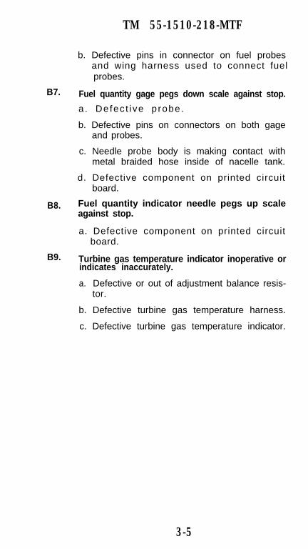
TM 55-1510-218-MTF
B7.
B8.
B9.
b. Defective pins in connector on fuel probesand wing harness used to connect fuelprobes.
Fuel quantity gage pegs down scale against stop.
a. Defec t i ve p robe.
b. Defective pins on connectors on both gageand probes.
c. Needle probe body is making contact withmetal braided hose inside of nacelle tank.
d. Defective component on printed circuitboard.
Fuel quantity indicator needle pegs up scaleagainst stop.
a. Defective component on printed circuitboard.
Turbine gas temperature indicator inoperative orindicates inaccurately.
a. Defective or out of adjustment balance resis-tor.
b. Defective turbine gas temperature harness.
c. Defective turbine gas temperature indicator.
3-5

TM 55-1510-218-MTF
TROUBLESHOOTING GUIDE C - ELECTRICAL
CONDITION
C1.
C2.
C3.
C4.
PROBABLE CAUSEZero or low voltage indicated.
a. Circuit breaker tripped.
b. Loose connection.
c. Open or shorted field circuit in generator ordefective armature.
d. Brushes not contacting commutator.
e. Brushes worn out.
f. Dirty commutator.
g. Defective voltage regulator.
No generator output.
a. Improper connections.
b. Circuit breaker tripped.
c. Open circuit.
d. Loss of residual magnetism.
e. Defective generator control switch.
f. Starter switch on.
g. Generator over-voltage circuit defective.
h. Paralleling circuit open.
i. Defective voltage regulator.
j. High resistance field circuit.
k. Shorted field.
Low generator output.
a. Generators not paralleled.
Low voltage.
a. Malfunctioning voltage regulator.
3-6

C5.
C6.
C7.
C8.
C9.
C10.
C11.
TM 55-1510-218-MTF
Volt-loadmeter reads off scale in wrong direc-tion.
a. Generator field magnetized in wrong direc-tion.
b. Generator leads reversed.
Volt-loadmeter does not indicate.
a. Tripped circuit breaker.
b. Open volt-loadmeter lead.
No power indicated with battery master switchON.
a. Battery discharged or defective.
b. Open circuit between battery and masterswitch.
c. Master switch defective.
d. Defective relay.
Power on with master switch in OFF position.
a. Master switch defective.
b. Relay contacts stuck.
Apparent loss or battery capacity.
a. Cells unbalanced.
b. Electrolyte level too low.
c. Charging rate too low in aircraft.
d. Too little usage or shallow discharges.
Complete failure of battery to operate.
a. Loose or broken lead.
b. Loose or disengaged terminals in battery.
c. Battery not charged.
d. Cell open internally.
Below normal battery output.
a. Battery switch left ON.
3-7
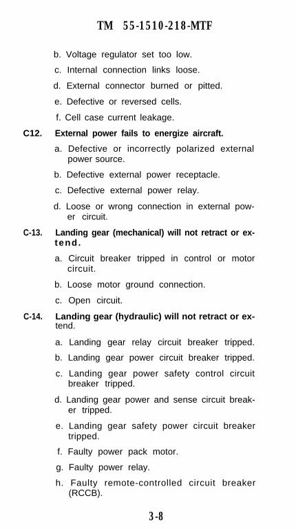
TM 55-1510-218-MTF
b. Voltage regulator set too low.
c. Internal connection links loose.
d. External connector burned or pitted.
e. Defective or reversed cells.
f. Cell case current leakage.
C12. External power fails to energize aircraft.
a. Defective or incorrectly polarized externalpower source.
b. Defective external power receptacle.
c. Defective external power relay.
d. Loose or wrong connection in external pow-er circuit.
C-13. Landing gear (mechanical) will not retract or ex-tend.
a. Circuit breaker tripped in control or motorcircuit.
b. Loose motor ground connection.
c. Open circuit.
C-14. Landing gear (hydraulic) will not retract or ex-tend.
a. Landing gear relay circuit breaker tripped.
b. Landing gear power circuit breaker tripped.
c. Landing gear power safety control circuitbreaker tripped.
d. Landing gear power and sense circuit break-er tripped.
e. Landing gear safety power circuit breakertripped.
f. Faulty power pack motor.
g. Faulty power relay.
h. Faulty remote-controlled circuit breaker(RCCB).
3-8

TM 55-1510-218-MTF
C15. Landing gear (mechanical) will extend but willnot retract.
a. Open circuit between landing gear switchand control relay.
b. Up solenoid of control relay inoperative.
c. Open circuit between control relay and upwinding in motor.
C16. Landing gear (hydraulic) fails to retract.
a. Safety switch not closing.
b. Pressure switch not closing.
c. Gear selector valve stuck.
d. Circuit is open between the selector valveand the power relay.
e. Time delay circuit opening prematurely.
f. Hand pump handle improperly stowed.
g. Service valve in up position.
C17. Landing gear (mechanical) will retract but willnot extend.
a. Open circuit.
b. Down limit switch inoperative.
c. Open circuit between control relay anddown winding of motor.
C18. Landing gear (hydraulic) fails to extend.
a. Service valve switches faulty.
b. Landing gear selector valve stuck in up posi-tion.
c. Control switch not providing power to theextend side of selector valve.
C19. Landing gear (mechanical) circuit breaker trips.
a. Grounded control circuit.
b. Grounded motor circuit.
c. Mechanical defect in gear causing overload.
3-9

TM 55-1510-218-MTF
C20. Landing gear (hydraulic) pump motor continuesto run after the gear is retracted, causing the cir-cuit breaker to trip.
a. Pressure switch not opening on high pres-sure.
b. Low accumulator charge.
c. Excessive fluid leakage past the piston sealsin the actuators.
d. Defective valve in the power pack.
C21. Landing gear (hydraulic) pump motor continuesto run after the gear are extended, causing thecircuit breaker to trip.
a. Downlock switches are not opening.
b. Power relay points stuck.
C22. Landing gear (hydraulic) pump motor continuesto run when the gear is extended or retracted,causing the circuit breaker to trip.
a. Weak power pack motor.
b. Low voltage to the motor.
c. Low fluid level.
d. Blockage in the hydraulic system.
C23. Landing gear (hydraulic) pump motor operatinglonger than 23 seconds in both the extension andretraction modes. The 2-ampere circuit breakerdoes not trip.
a. Low voltage.
C24. Landing gear (hydraulic) pump motor operatinglonger than 23 seconds in the retract mode, butthe 2-ampere circuit breaker does not trip.
a. Faulty time delay PCB and pressure switch.
C25. Landing gear (hydraulic) pump motor operatinglonger than 23 seconds in the extended modebut the 2 ampere circuit breaker does not trip.
a. Downlock switches failing to open and/orthe time delay PCB is faulty.
3-10

TM 55-1510-218-MTF
C26. Landing gear (hydraulic) low fluid level light notfunctioning.
a. Defective lamp.
b. Defective fluid indicator circuit.
C27. Landing gear (hydraulic) circuit breaker trips.
a. Shorted circuit.
C28. Landing gear (mechanical) operation noisy.
a. Loose chain.
b. Broken gear door linkage.
c. Worn actuator bearings.
C29. Landing gear (Mechanical) warning horn inoper-ative.
a. Defective warning horn.
b. Power lever switch out of adjustment.
c. Defective landing gear control switch.
d. Defective safety switch.
e. Defective wiring.
C30. Landing gear (mechanical) warning born inoper-ative when Ianding gear control switch is in theup position and weight of aircraft is on struts,but operates when a power lever is closed andthe gear is retracted.
a. Poor ground at landing gear control switch.
b. Defective wiring between landing gear con-trol switch, fire warning horn relay and land-ing gear safety switch.
C31. Landing gear (mechanical) warning horn inoper-ative when power lever is closed and landinggear is up.
a. Defective or out of adjustment power leverswitch.
b. Defective wiring between power leverswitches and pedestal terminal board, and
3-11

TM 55-1510-218-MTF
between landing gear control switch andhorn relay.
C32. Landing gear (mechanical) warning horn fails toshut off when landing gear is extended.
a. Defective or out of adjustment down-lockswitches.
C33. Landing gear (mechanical) down position indica-
tracted.tor lights are illuminated with landing gear re-
a. defective or out of adjustment down lockswitch.
b. Wrong connection in light test circuit.
c. Ground between light and down lock switch.
C34. Landing gear (mechanical) down position indica-tor light inoperative.a. Defective or out of adjustment down lock
switch.
C35. Landing gear (mechanical) handle light is illu-minated with gear up and locked.
a. Defective or out of adjustment up-lockswitch.
C36. Landing gear (mechanical) handle light inopera-t ive .
a. Defective or out of adjustment up-lock ordown-lock switch.
b Defective landing gear control switch.
C37. Flaps fail to extend or retract.
a. Tripped cicuit breaker.
b. Defective flap motor.
c. Defective flap control switch.
d. Defective mechanical component in actuatorsystem.
e. Defective wiring.
3-12

TM 55-1510-218-MTF
C38. Flap position indicator inoperative.
a. Tripped circuit breaker.
b. Defective position indicator.
c. Defective position transmitter.
d. Defective wiring.
C39. Pitot tube heater fails to operate
a. Tripped circuit breaker.
b. Defective heater.
c. Defective wiring.
C40. Stall warning system inoperative.
a. Defective stall warning switch.
b. Defective stall warning horn.
c. Defective wiring.
C41. Stall warning horn sounds continuously.
a. Defective stall warning switch.
b. Defective stall warning test system.
c. Defective wiring.
C42. Both inverters inoperative.
a. Tripped inverter circuit breakers (on DCpower distribution panel beneath floor).
b. Defective inverter select switch.
c. Defective wiring in inverter system.
C43. One inverter inoperative.
a. Tripped inverter circuit breaker (on DCpower distribution panel beneath floor).
b. Tripped generator fault circuit breaker.
c. Defective current limiter.
d. Defective inverter.
e. Defective inverter power relay.
3-13

TM 55-1510-218-MTF
f. Loose or corroded ground connection.
g. Defective wiring to inverter.
C44. Battery charge annunciator light inoperative.
a. Defective light bulb.
b. Connections on current detector loose orcorroded.
c. Defective current detector printed circu.board assembly.
C45. One portion of interior lighting or lighting con-trol system inoperative.
a. Defective light circuit board or wheat lights.
b. Defective components in overhead controlpanel.
c. Defective power supply.
C46. Fuel crossfeed valve inoperative or fuel fail Iightremains illuminated.
a. Defective standby fuel pump.
b. Defective crossfeed valve.
C47. Standby fuel pump inoperative.
a. Defective standby pump relay.
b. Defective switch in fuel management panel
c. Defective fuel pressure switch.
C48. Pnuematic surface deicer system inoperative.
a. Defective surface deicer control relay.
C49. Right and left FIRE PULL warning lights donot illuminate in my test position of fire protec-tion test switch.
a. Tripped fire detector circuit breaker.
b. Defective fire protection test switch.
c. Defective wiring.
C50. Engine fire detection system wholly or partiallyinoperative.
3-14
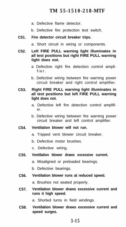
TM 55-1510-218-MTF
C51.
C52.
C53.
C54.
C55.
C56.
C57.
C58.
a. Defective flame detector.
b. Defective fire protection test switch.
Fire detector circuit breaker trips.
a. Short circuit in wiring or components.
Left FIRE PULL warning light illuminates inall test positions but right FIRE PULL warninglight does not.
a Defective right fire detection control ampli-f i e r .
b. Defective wiring between fire warning powercircuit breaker and right control amplifier.
Right FIRE PULL warning light illuminates inall test positions but left FIRE PULL warninglight does not.
a. Defective left fire detection control amplifi-er.
b. Defective wiring between fire warning powercircuit breaker and left control amplifier.
Ventilation blower will not run.
a. Tripped vent blower circuit breaker.
b. Defective motor brushes.
c. Defective wiring.
Ventilation blower draws excessive current.
a. Misaligned or preloaded bearings.
b. Defective bearings.
Ventilation blower runs at reduced speed.
a. Brushes not seated properly.
Ventilation blower draws excessive current andruns it high speed.
a. Shorted turns in field windings.
Ventilation blower draws excessive current andspeed surges.
3-15
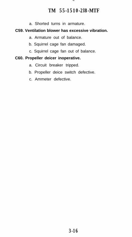
TM 55-1510-2l8-MTF
a. Shorted turns in armature.
C59. Ventilation blower has excessive vibration.
a. Armature out of balance.
b. Squirrel cage fan damaged.
c. Squirrel cage fan out of balance.
C60. Propeller deicer inoperative.
a. Circuit breaker tripped.
b. Propeller deice switch defective.
c. Ammeter defective.
3-16

TM 55-1510-218-MTF
TROUBLESHOOTING GUIDE D - CAUTIONPANEL
CONDITION
D1.
D2.
D3.
D4.
PROBABLE CAUSEPlacard light (annunciator panel) will not illumi-nate when press-to-test button is pressed.a. Defective placard Iight.
Fault warning light will not illuminate for anyred faults.a. Defective fault warning light.
b. Defective fault warning light resistor.
c. Defective annunciator control box.
Depressing the press-to-test switch has no effecton fault warning system operation.a. Defective switch.
b. Defective annunciator control box.
Dim control does not function properly.a. Defective rheostat.
b. Defective dim bias resistor.
c. Defective annunciator control box.
3-17

TM 55-151-218-MTF
TROUBLESHOOTING GUIDE E - POWERPLANT
CONDITION
E1.
E2.
E3.
E4.
E5.
E6.
E7.
E8.
PROBABLE CAUSELOW IDLE speed is either high or low.
a. LOW IDLE speed improperly adjusted.
HIGH IDLE speed is either high or low.a. HIGH IDLE speed improperly adjusted.
Low or high torque is observed during torquecheck.a. Barrel adjustable stop is improperly adjust-
ed.
Reverse torque, N1, and propeller RPM is toohigh or low.a. Reverse adjusting screw is improperly ad-
justed.
Newly rigged engine accelerates faster or slowerthan opposite engine.a. Engine rigging, components. or engine is
mismatched.
Power levers are not aligned.a. Fuel control rod improperly adjusted.
High engine oil pressure.a. Defective oil pressure indicating system.
b. Defective pressure relief valve.
Low engine oil pressure.
a. Insufficient oil.
b. Defective oil pressure indicating system.
c. Dirty oil filter.d. Leak in oil lines or oil cooler.
e. Defective pressure relief valve.
3-18

TM 55-1510-218-MTF
f. Excessive hot air leakage through faulty heatshielding.
E9. Fluctuating engine oil pressure.
a. Insufficient or excess oil.
b. Defective oil pressure indicating system.
c. Dirty oil filter.
d. Defective pressure relief valve.
E10. High oil temperature.a. Insufficient oil supply.
b. Defective oil temperature indicating system.
c. Excessive idling in feather.
d. Restriction in oil cooler.
E11. Oil leak from compressor inlet.a. Defective preformed packing and plastic
ring on oil filter housing.
b. Defective preformed packings on accessorygearbox.
E12. Excessive oil discharge from overboard breather.a. Excess oil in tank.b. Defective preformed packing and plastic
ring on oil filter.c. Excessive back pressure in scavenge system
due to restrictions in oil scavenge tubes.pump screen or oil-to-fuel heater tubes.
E13. Excessive engine oil consumption.a. Excess oil in tank.b. Leak or restriction in pressure scavenge oil
tube.c. Defective preformed packing and plastic
ring on oil filter housing.
d. Leakage in oil to fuel heat exchanger.
e. Defective centrifugal breather carbon seal.
3-19

TM 55-1510-218-MTF
f. Defective air seals.
E14. Failure of engine to decelerate.a. Fuel control unit.
b. Disconnected or improperly adjusted link-age.
E15. Gas generator overspeed.
a. Defective turbine tachometer system.
b. Sheared or worn fuel control unit splined.coupling or drive spline.
c. Defective fuel control unit.
E16. Gas generator uncontrolled acceleration.
a. Sheared or worn fuel control unit splinedcoupling or drive spline.
b. Defective fuel control unit.
E17. Surge during acceleration.a. Defective compressor bleed valve.
b. Defective fuel control unit.
c. Compressor damaged.
E18. Slow to accelerate..
a. Leak or restriction in fuel control unit sensetubes.
b. Fuel control contaminated with ice or corro-sion.
c. Defective fuel control unit.
d. Leaking bleed air valve.
E19. Flame out.
a. Fuel supply contaminated with ice, water ordebris.
b. Engine driven high pressure fuel pump.
c. Fuel control unit contaminated or corroded.d. Manifold adapter or fuel nozzles restricted.
3-20
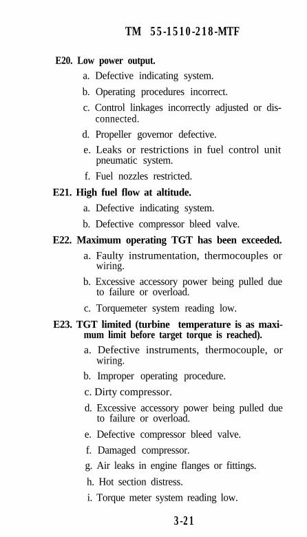
TM 55-1510-218-MTF
E20. Low power output.a. Defective indicating system.
b. Operating procedures incorrect.
c. Control linkages incorrectly adjusted or dis-connected.
d. Propeller governor defective.
e. Leaks or restrictions in fuel control unitpneumatic system.
f. Fuel nozzles restricted.
E21. High fuel flow at altitude.
a. Defective indicating system.
b. Defective compressor bleed valve.
E22. Maximum operating TGT has been exceeded.
a. Faulty instrumentation, thermocouples orwiring.
b. Excessive accessory power being pulled dueto failure or overload.
c. Torquemeter system reading low.
E23. TGT limited (turbine temperature is as maxi-mum limit before target torque is reached).a. Defective instruments, thermocouple, or
wiring.
b. Improper operating procedure.
c. Dirty compressor.
d. Excessive accessory power being pulled dueto failure or overload.
e. Defective compressor bleed valve.
f. Damaged compressor.
g. Air leaks in engine flanges or fittings.
h. Hot section distress.
i. Torque meter system reading low.
3-21

TM 55-1510-218-MTF
E24. Fluctuating torque indication.a. Faulty instrumentation system.
b. Defective power turbine governor.c. Engine driven high pressure pump shaft seal
leakage.d. Defective or out of adjustment propeller
overspeed governor.
e. Defective propeller primary governor.
f. Sticking beta mechanism.
E25. Fluctuating fuel flow.a. Faulty instrumentation system.
b. Defective power turbine governor.
c. Engine driven high pressure fuel pump shaftseal leaking.
d. Defective propeller overspeed governor.
e. Sticking beta mechanism.
E26. Fluctuating TGT.a. Faulty instrumentation system.
b. Defective power turbine governor.
c. Defective engine driven high pressure fuelpump shaft seal.
d. Defective or out of adjustment propelleroverspeed governor.
e. Defective propeller primary governor.f. Sticking beta mechanism.
E27. Fluctuating gas generator speed.a. Faulty instrumentation system.
b. Defective power turbine governor.
c. Defective engine driven primary high pres-sure fuel pump shaft seal.
d. Defective or out of adjustment propelleroverspeed governor.
3-22

TM 55-1510-218-MTF
e. Defective propeller primary governor.
f. Sticking beta mechanism.
E28. Fluctuating torque and propeller RPM.a. Defective or out of adjustment propeller
overspeed governor.
b. Defective propeller primary governor.
c. Sticking beta mechanism.
E29. Fuel leaking overboard.
a. Fuel cap not seated.
b. Filler cap or preformed packing defective.
c. Fuel transfer pump relay defective.
d. Fuel level transmitter defective.
E30. Slow to accelerate.a. Possible leak or restriction in Py air bleed
tube or P3 air delivery tube.
b. P3 air filter needs replacing.
c. Improper acceleration adjustment on fuelcontrol unit.
d. Propeller governor out of adjustment.
e. Defective fuel control unit.
f. Defective propeller governor.
3-23
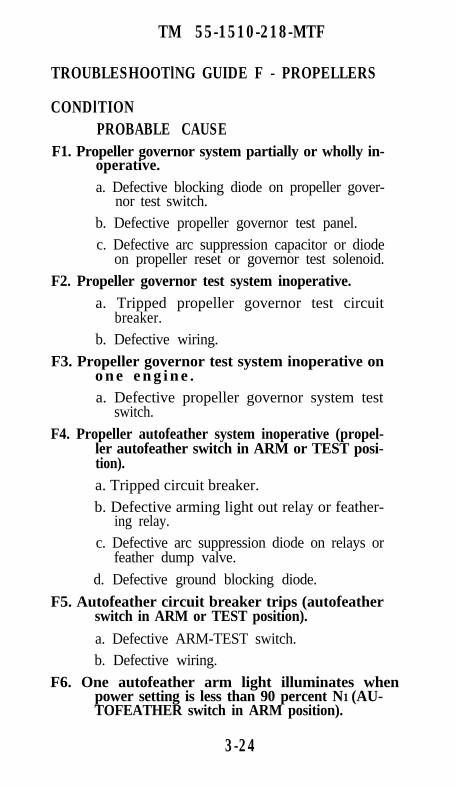
TM 55-1510-218-MTF
TROUBLESHOOTlNG GUIDE F - PROPELLERS
CONDlTIONPROBABLE CAUSE
operative.F1. Propeller governor system partially or wholly in-
F5. Autofeather circuit breaker trips (autofeather
F6. One autofeather arm light illuminates when
d. Defective ground blocking diode.
switch in ARM or TEST position).
a. Defective ARM-TEST switch.b. Defective wiring.
power setting is less than 90 percent N1 (AU-TOFEATHER switch in ARM position).
feather dump valve.c. Defective arc suppression diode on relays or
b. Defective arming light out relay or feather-ing relay.
a. Tripped circuit breaker.
ler autofeather switch in ARM or TEST posi-tion).
F4. Propeller autofeather system inoperative (propel-
a. Defective propeller governor system testswitch.
o n e e n g i n e .F3. Propeller governor test system inoperative on
F2. Propeller governor test system inoperative.
b. Defective wiring.
a. Defective blocking diode on propeller gover-nor test switch.
b. Defective propeller governor test panel.c. Defective arc suppression capacitor or diode
on propeller reset or governor test solenoid.
a. Tripped propeller governor test circuitbreaker.
3-24
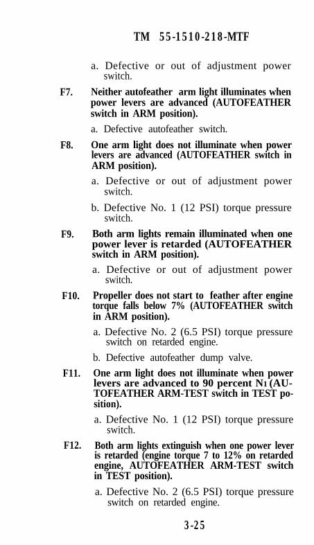
F7.
F8.
F9.
F10.
F11.
F12.
TM 55-1510-218-MTF
a. Defective or out of adjustment powerswitch.
Neither autofeather arm light illuminates whenpower levers are advanced (AUTOFEATHERswitch in ARM position).a. Defective autofeather switch.
One arm light does not illuminate when powerlevers are advanced (AUTOFEATHER switch inARM position).a. Defective or out of adjustment power
switch.
b. Defective No. 1 (12 PSI) torque pressureswitch.
Both arm lights remain illuminated when onepower lever is retarded (AUTOFEATHERswitch in ARM position).a. Defective or out of adjustment power
switch.
Propeller does not start to feather after enginetorque falls below 7% (AUTOFEATHER switchin ARM position).a. Defective No. 2 (6.5 PSI) torque pressure
switch on retarded engine.
b. Defective autofeather dump valve.
One arm light does not illuminate when powerlevers are advanced to 90 percent N1 (AU-TOFEATHER ARM-TEST switch in TEST po-sition).a. Defective No. 1 (12 PSI) torque pressure
switch.
Both arm lights extinguish when one power leveris retarded (engine torque 7 to 12% on retardedengine, AUTOFEATHER ARM-TEST switchin TEST position).
a. Defective No. 2 (6.5 PSI) torque pressureswitch on retarded engine.
3-25
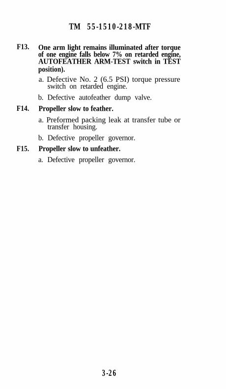
F13.
F14.
F15.
TM 55-1510-218-MTF
One arm light remains illuminated after torqueof one engine falls below 7% on retarded engine,AUTOFEATHER ARM-TEST switch in TESTposition).a. Defective No. 2 (6.5 PSI) torque pressure
switch on retarded engine.
b. Defective autofeather dump valve.
Propeller slow to feather.
a. Preformed packing leak at transfer tube ortransfer housing.
b. Defective propeller governor.
Propeller slow to unfeather.a. Defective propeller governor.
3-26

TM 55-1510-218-MTF
TROUBLESHOOTING GUIDE G - HYDRAULIC
CONDITION
G1.
G2.
G3.
G4.
G5.
G6.
G7.
G8.
PROBABLE CAUSESolid pedal, no brakes.
a. Brake linings worn beyond allowable limits.
Spongy brakes.a Air in brake hydraulic system.
b. Low hydraulic fluid.
Unable to hold brake pressure.a. Leak in brake hydraulic system.
b. Brake cylinder seal leaking.
Brake pedals bottom, no brakes.a. Broken or leaking hydraulic lines.b. Brake cylinder seal failure.
Parking brake will not hold.a. Air in brake hydraulic system.
b. Defective parking brake valve.
c. Parking brake control out of adjustment.
Brakes grab.a. Stones or foreign matter locking brake disc.
b. Warped or bent disc.
Brakes drag.a. Packing nut or threaded bushing, as applica-
ble, too loose.
Brakes weak.a. Packing nut or threaded bushing, as applica-
ble, too tight.
3-27

TM 55-1510-218-MTF
TROUBLESHOOTING GUIDE H - FLIGHT CON-TROLS
CONDITIONPROBABLE CAUSE
For complete troubleshooting of autopilot system, re-fer to Collins manual P/N 523-0764802-00111A.
3-28

TM 55-1510-218-MTF
TROUBLESHOOTlNG GUIDE I - NOT APPLICA-BLE
3-29

TM 55-1510-218-MTF
TROUBLESHOOTING GUIDE J - VIBRATIONS
CONDITIONPROBABLE CAUSE
J1. Engine vibration.a. Propeller damaged or blade angle slipped.
b. Loose engine mounting bracket bolts.
c. Compressor damaged.
d. Turbine damaged.
3-30

TM 55-1510-218-MTF
TROUBLESHOOTlNG GUIDE K - COMMUNICA-TION/NAVIGATION EQUIPMENTK1.
K2.
K4.
K5.
K3.
K6.
K7.
K8.
Interphone system: No audio signals heard inheadsets.
a. No power to audio system.
b. Defective microphone, control wheel micro-phone switch, or foot microphone switch.
c. Defective headset-microphone cord or jack.
d. Defective microphone jack.
e. Defective audio control panel.
Interphone system: Audio signals can be heardat other headset stations when transmitter selec-to switches at audio control panel are at differ-ent positions.a. Defective audio control panel.
b. Defective wiring.
UHF VOL control has no effect on receivernoise or incoming signal.
a. Defective UHF command set.
UHF channeling tone not heard.a. Defective UHF command set.
UHF squelch switch has no effect on receivernoise.a. Defective UHF command set.
b. Defective static wicks.
UHF guard receiver noise not audible.
a. Defective UHF command set.
Cannot establish UHF two-way communications.
a. Defective audio distribution channels.
b. Defective antenna or antenna cabling.
Cannot establish VHF two-way communications.
a. Defective audio distribution channels.
3-31
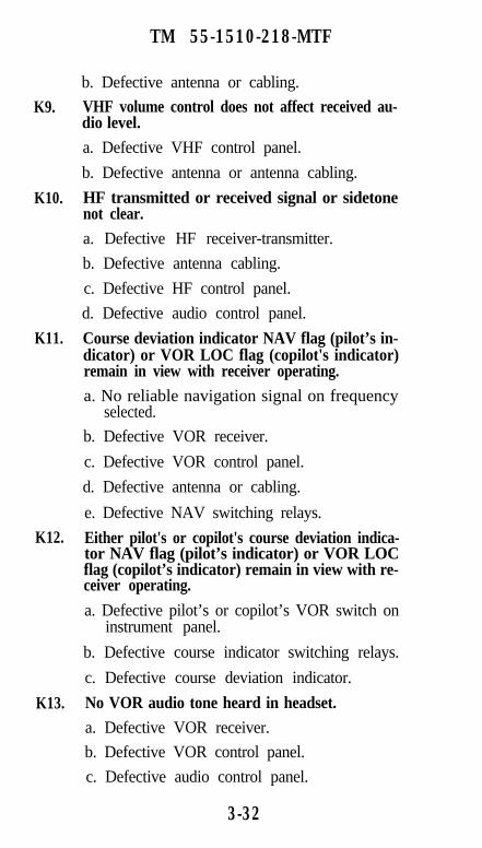
K9.
K10.
K11.
K12.
K13.
TM 55-1510-218-MTF
b. Defective antenna or cabling.
VHF volume control does not affect received au-dio level.
a. Defective VHF control panel.
b. Defective antenna or antenna cabling.
HF transmitted or received signal or sidetonenot clear.
a. Defective HF receiver-transmitter.
b. Defective antenna cabling.
c. Defective HF control panel.
d. Defective audio control panel.
Course deviation indicator NAV flag (pilot’s in-dicator) or VOR LOC flag (copilot's indicator)remain in view with receiver operating.
a. No reliable navigation signal on frequencyselected.
b. Defective VOR receiver.
c. Defective VOR control panel.
d. Defective antenna or cabling.
e. Defective NAV switching relays.
Either pilot's or copilot's course deviation indica-tor NAV flag (pilot’s indicator) or VOR LOCflag (copilot’s indicator) remain in view with re-ceiver operating.
a. Defective pilot’s or copilot’s VOR switch oninstrument panel.
b. Defective course indicator switching relays.
c. Defective course deviation indicator.
No VOR audio tone heard in headset.
a. Defective VOR receiver.
b. Defective VOR control panel.
c. Defective audio control panel.
3-32

TM 55-1510-21-MTF
c. Defective course deviation indicator.
K18. Glideslope indicator on course deviation indica-tors do not deflect properly.a. Defective glideslope portion of VOR receiv-
er.
K19. Glideslope indicator on one course deviation in-dicator does not deflect properly.
a. Defective course deviation indicator.
b. Defective course deviation indicator switch-ing relay.
a. Defective pilot’s or copilot’s VOR switch oninstrument panel.
c. Defective VOR control panel.
K17. Glideslope off flag on one course deviation indi-cator remains in view when glideslope receiver isoperating.
b. Defective glideslope antenna or cabling.
K16. Glideslope off flags remain in view when glide-slope receiver is operating. a. Glideslope portion of VOR receiver defec-
tive.
K14. Marker beacon indicator light does not illumi-nate.a. Defective marker beacon indicator light.
b. No power to receiver.
c. Defective antenna or cabling.
d. Defective marker beacon off/volume controlon audio control panel.
e. Defective marker beacon receiver.
K15. Marker beacon signals not heard in headset.
a. Defective audio control panel.
b. Defective marker beacon off/volume controlor sensitivity switch on audio control panel.
3-33

TM 55-1510-218-MTF
b. Defective course deviation indicator switch-ing relay.
K20. ADF radio set inoperative.a. No power to ADF radio set.
K21. No ADF audio heard in headsets and tuning me-ter does not deflect.
a. Defective ADF receiver.
b. Defective ADF control panel.
c. Defective ADF sense antenna.
K22. Radio magnetic indicator does not indicate mag-netic bearing to station with single or doubleneedle switch to ADF.a. Defective ADF receiver.
b. Defective RMI.
c. Defective ADF fixed-loop antenna.
d. Defective ADF-VOR switch on RMI.
c. Defective ADF control panel.
K23. ADF single needle pointer does not return to sta-tion bearing.a. Defective RMI.
K24. Quality of ADF reception is poor.
a. Defective ADF control panel.
b. Defective audio control panel.
c. Defective ADF receiver.
K25. Heading on course deviation indicator does notagree with magnetic compass heading of aircraft(corrected for compass deviation).
a. Defective gyro compass set.
b. Incorrect compass deviation card.
K26. Copilot’s radio magnetic indicator heading doesnot agree with pilot's radio magnetic indicatorheading within two degrees.
3-34
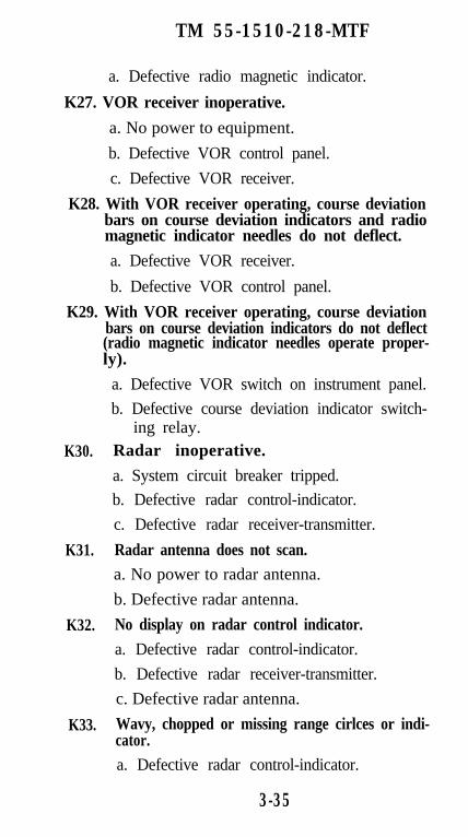
TM 55-1510-218-MTF
a. Defective radio magnetic indicator.
K27. VOR receiver inoperative.
a. No power to equipment.
b. Defective VOR control panel.
c. Defective VOR receiver.
K28. With VOR receiver operating, course deviationbars on course deviation indicators and radiomagnetic indicator needles do not deflect.
a. Defective VOR receiver.
b. Defective VOR control panel.
K29. With VOR receiver operating, course deviationbars on course deviation indicators do not deflect(radio magnetic indicator needles operate proper-ly).
K30.
K31.
K32.
K33.
a. Defective VOR switch on instrument panel.
b. Defective course deviation indicator switch-ing relay.
Radar inoperative.
a. System circuit breaker tripped.
b. Defective radar control-indicator.
c. Defective radar receiver-transmitter.
Radar antenna does not scan.a. No power to radar antenna.
b. Defective radar antenna.
No display on radar control indicator.
a. Defective radar control-indicator.
b. Defective radar receiver-transmitter.
c. Defective radar antenna.
Wavy, chopped or missing range cirlces or indi-cator.a. Defective radar control-indicator.
3-35
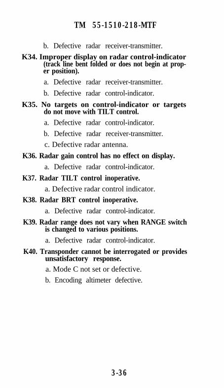
TM 55-1510-218-MTF
b. Defective radar receiver-transmitter.
K34. Improper display on radar control-indicator(track line bent folded or does not begin at prop-er position).a. Defective radar receiver-transmitter.
b. Defective radar control-indicator.
K35. No targets on control-indicator or targetsdo not move with TILT control.a. Defective radar control-indicator.
b. Defective radar receiver-transmitter.
c. Defective radar antenna.
K36. Radar gain control has no effect on display.a. Defective radar control-indicator.
K37. Radar TILT control inoperative.a. Defective radar control indicator.
K38. Radar BRT control inoperative.a. Defective radar control-indicator.
K39. Radar range does not vary when RANGE switchis changed to various positions.a. Defective radar control-indicator.
K40. Transponder cannot be interrogated or providesunsatisfactory response.a. Mode C not set or defective.
b. Encoding altimeter defective.
3-36

TM 55-1510-218-MTF
SECTION IV. SPECIAL PROCEDURES
General. This section contains the special proceduresthat were referenced in section II.*A. Pressurization and Oxygen System. Check as
follows:
1. Bleed air valve switches (2) - OPEN.
2. After takeoff - Establish a climb.
3. Cabin altimeter - After takeoff the cabin altime-ter needle should stabilize at selected altitude±250 feet and the cabin differential pressureneedle should continue climbing. The cabin al-timeter needle should remain at selected altitudeuntil the maximum pressure differential of 6.0±.1 is reached. At this point (approximately 16,600 feet pressure altitude) the cabin altitudeshould increase while the differential pressureremains constant.
a. Cabin pressurization leak rate - Check with-in limits as follows:
b. Level off aircraft when pressure differentialreaches 60±.1.
c. Bleed air valve switches (2) - ENVIRO OFF.
* 4. Cabin rate-of-climb indicator - Read and recordcabin rate of climb. Cabin rate of climb (cabinpressurization leak rate) should not exceed 2200feet per minute.
5. Bleed air valve switches (2) - OPEN. Re-establish 6.0±.1 PSI cabin pressure differential,
6. Left bleed air valve switch - ENVIRO OFF.
* 7. Slowly retard the right power lever and recordthe minimum N1 speed that the Right enginemust be operated at to maintain the cabin pres-sure differential at 6.0+1. N1 should not exceed85%. and the minimum desirable N1 is 80%.
8. Left bleed air valve switch - OPEN.
9. Right bleed air valve switch - ENVIRO OFF.
4-1

TM 55-1510-218-MTF
* 10. Slowly retard the left power lever and record theminimum N1 speed that the left engine must beoperated at to maintain the cabin pressure dif-ferential at 6.0±1. N1 should not exceed 85%.and the minimum desireable N1 is 80%.
11. Right bleed air valve switch - OPEN.
12. Cabin altitude controller - Set to 10,000 feetpressure altitude.
13. Cabin pressurization rate knob - Set to maxi-mum.
* 14. Cabin rate of climb indicator - Read and record.Cabin rate of descent should be between 1500and 2500 feet per minute.
15. Cabin pressurization rate knob - Set to mid-range.
* 16. Cabin rate of climb indicator - Read and recordcabin rate of descent. Cabin rate of descentshould be between 350 and 650 feet per minute.
17. Cabin pressurization rate knob - Set to mini-mum.
* 18. Cabin rate of climb indicator - Read and recordcabin rate of descent. Cabin rate of descentshould be between 50 and 300 feet per minute.
19. Cabin altitude controller - Set.* 20. Cabin rate of climb indicator - Read and record
cabin rate of descent. Cabin rate of descentshould be between 50 and 350 feet per minute.
21. Cabin pressurization rate knob - Set to maxi-mum.
* 22. Cabin rate of climb indicator - Read and recordcabin rate of descent. Cabin rate of descentshould be between 1500 and 2500 feet per min-ute.
23. Cabin pressurization rate knob - Set to mid-range.
* 24. Cabin rate of climb indicator - Read and recordcabin rate of descent. Cabin rate of descentshould be between 350 and 650 feet per minute.
4-2

TM 55-1510-218-MTF
25. Cabin altitude controller - Set to 10,000 feet.
26. Cabin pressurization rate control - Set to a com-fortable rate of climb.
* 27. Cabin altitude indicator - Read and record alti-tude. Altitude should reach 9750 to 10,250 feetpressure altitude.
28. Aircraft altitude - 10,000 feet.
29. Cabin pressurization dump switch - DUMP.
30. Aircraft altitude - Increase toward 12,500 feetpressure altitude.
* 31. Cabin altitude warning annunciator light -Check that it illuminates between 12,000 and12,500 feet pressure altitude.
* 32. Oxygen system - Check that automatic deploy-ment of masks occurs between 12,000 and 12,500 feet pressure altitude (C-12D).
* 33. Cabin lights - Check that they automatically illu-minate between 12,000 and 12,500 feet pressurealtitude.
34. Cabin pressurization dump switch - PRESS.
35. Cabin altitude controller - Set to field elevation.
36. Descend toward field altitude.
* 37. Cabin altitude indicator - Check that cabin alti-tude attains and remains at field elevation ±250feet until the altitude set in the cabin altitudecontroller is reached by the aircraft.
* 38. Oxygen system (after landing) - Check eachmask for function and condition.
*B. Trim and Rigging. Check as follows:
1. In smooth air, at cruise power, the aircraft willfly hands off, straight and level with the aileronssymmetrically aligned at the trailing edge andthe aileron adjustable tab set to zero.
2. For additional trim and rigging checks, refer tomaintenance manual, P/N 92-37443-1.
4-3

TM 55-1510-218-MTF
*C. Maximum Power Lever Position Check. Enginesshall be able to operate within N1 or TGT limits atmaximum power lever position, and be off the torquelimit, at 2000 propeller RPM. Check maximum powerlever position as follows:
NOTE
The only requirement of the maximum pow-er lever position check is to verify that it ispossible to obtain maximum allowable gasgenerator RPM (N1) with the power leversin the full forward position. If during thetest the TGT temperature limit or N1 limitis obrained prior to reaching maximum N1,the check is completed.
1.
2.
3.
4.
5.
6.
Altitude - 25,000 feet pressure altitude.
Propeller levers - Set 2000 RPM.
Ice vanes - Retracted.
Bleed air valve switches - OPEN.
Airspeed - As required.
Power levers - Full forward (do not exceed TGTand/or N1 limits). For PT6A-41 engine maxi-mum N1 is 101.5% and maximum TGT is750°C. For PT6A-42 engine maximum N1 is101.5% and maximum TGT is 800°C.
4-4
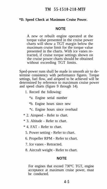
TM 55-1510-218-MTF
*D. Speed Check at Maximum Cruise Power.
NOTE
A new or rebuilt engine operated at thetorque value presented in the cruise powercharts will show a TGT margin below themaximum cruise limit for the torque valuepresented in the charts. With ice vanes re-tracted, if cruise torque settings shown onthe cruise power charts should be obtainedwithout exceeding TGT limits.
Sped-power runs shall be made in smooth air to de-termine consistency with performance figures. Torquesettings, fuel flow, and airspeed to be achieved will bedetermined by reference to maximum cruise powerand speed charts (figure 9 through 14).
1. Record the following:
*a. Engine serial number
*b. Engine hours since new
*c. Engine hours since overhaul
* 2. Airspeed - Refer to chart.
* 3. Altitude - Refer to chart.
* 4. FAT - Refer to chart.
5. Power setting - Refer to chart.
6. Propeller RPM - Refer to chart.
7. Ice vanes - Retracted.
8. Aircraft weight - Refer to chart.
NOTE
For engines that exceed 730°C TGT, engineacceptance at maximum cruise power, mustbe conducted.
4-5

TM 55-1510-218-MTF
*E. Engine Acceptance (C-12C and C-12D).
1. Record the following
*a. Engine serial number.
*b. Engine hours since new.
*c. Engine hours since overhaul.
2. Propeller levers - Set 1900 RPM.
3. Ice vanes - Retract.
4. Bleed air valve switches - OPEN.
5. Electrical load - 0.5% or less per engine.
6. Altitude - Refer to applicable chart.
7. Set engine torque as specified by the engine ac-ceptance graph (figure 13 or 14) on the engine tobe tested.
8. Adjust the opposite engine to maintain 175KIAS.
NOTE
Aircraft performance is based on obtainingat least chart torque. Any engine must beable to meet the chart torque value withoutexceeding the TGT of 750°C.
9. Allow conditions to stabilize for one minutethen record the following for each engine beingtested:
*a. Airspeed
*b. Pressure altitude
*c. Free air temperature
*d. TGT
*e. Propeller RPM
*f. Torque
*g. N1
4-6

TM 55-1510-218-MTF
10. Repeat for opposite engine.
*F. Engine Acceptance at Maximum Continuous Pow-er (C-12F).
1. Record the following
*a. Engine serial number.
*b. Engine hours since new.
*c. Engine hours since overhaul.
2. Altitude -Establish level flight at 16,000 feetpressure altitude.
3. Propeller levers - Set 2000 RPM.
4. Adjust the opposite engine to maintain 160KIAS.
5. Set engine torque as specified by the engine ac-ceptance graph (figure 15) on the engine to betested.
NOTE
Aircraft performance is based on obtainingat least chart torque. Any engine must beable to meet the chart torque value withoutexceeding the TGT of 780°C.
6. Allow conditions to stabilize for one minutethen record the following for each engine beingtested:
*a. Airspeed
*b. Pressure altitude
*c. Free air temperature
*d. TGT
*e. Propeller RPM
*f. Torque
* g . N1
4-7
TM 55-1510-218-MTF
7. Repeat for opposite engine.
*G. Engine Acceptance at Maximum Cruise Power(C-12F).
NOTE
The engine acceptance at maximum cruisepower check needs to be performed only ifthe TGT observed during the engine accep-tance check at maximum continuous powerexceeds 780°C.
1. Record the following:
*a. Engine serial number.
*b. Engine hours since new.
*c. Engine hours since overhaul.
2. Altitude -Establish level flight at 25,000 feetpressure attitude.
3. Propeller levers - Set 1900 RPM.
4. Adjust the opposite engine to maintain 175KIAS.
5. Free air temperature - Record.
6. Set engine torque as specified by the engine ac-ceptance graph (figure 15) for the recorded indi-cated free air temperature. on the engine to betested.
7. Allow conditions to stabilize for one minutethen record the following for each engine be-ing tested:
*a. Airspeed
*b. Pressure altitude
*c. Free air temperature
*d. TGT (must not exceed 780°C)
*e. Propeller RPM
4-8

TM 55-1510-218-MTF
*f. Torque
*g. N1
8. Repeat for opposite engine
4-9

TM 55-1510-218-MTF
H. Avionics Flight Checks.
PROCEDURE TROUBLESHOOTINGREFERENCE
* 1. VLF/omega navigation systemflight test - Perform as follows:
A triangular test flight shall be performed Sastisfacto-ry performance shall be demonstrated by flying overthree checkpoints whose latitude and longitude areknown, and comparing them with the VLF/omega co-ordinate readouts. The aircraft shall establish a lowaltitude, compatible with aircraft safety and applica-ble Laws and Codes of Flight which will allow accu-rate sighting of ground landmarks. An altitude of1000 feet is recommended whenever possible.
a. VLF/Omega navigation sys-tem - Set up and operate inaccordance with TM 55-1510-218-10.
b. Insert the coordinates of twodistant ground checkpointsand point of departure. Dis-tances between pound check--points should be far enoughapart to provide a 1 hour tri-angular closed course.
c. Fly the triangular course andmonitor the navigation instru-ments for proper operation.
*d. Record the distances from theknown ground checkpoints tothe corresponding waypointlocation provided by theVLF/Omega navigation sys-tem. Maximum permissiblealong-track or cross-track er-ror for each checkpoint is1.75 statute miles.
4-10

TM 55-1510-218-MTF
PROCEDURE TROUBLESHOOTINGREFERENCE
*2. Flight management system (KNS-660) flight test - Perform as fol-lows:
A triangular test flight shall be performed. Satisfacto-ry performance shall be demonstrated by flying overthree checkpoints whose latitude and longitude areknown, and comparing them with the flight manage-ment system coordinate readouts. The aircraft shallestablish a low altitude, compatible with aircraft safety and applicable Laws and Codes of Flight which willallow accurate sighting of ground landmarks. An alti-tude of 1000 feet is recommended whenever possible.
a. Flight management system -Set up and operate in accor-dance with TM 55-1510-218-10.
b. Insert the coordinates of twodistant ground checkpointsand point of departure. Dis-tances between ground check-points should be far enoughapart to provide a 1 hour tri-angular closed course.
c. Fly the triangular course andmonitor the navigation instru-ments for proper operation.
d. Check the operation of thesystem in the RNAV ENR-mode, and verify the opera-tion of each sensor (BLEND,VOR, TACAN, VLF/OMEGA, and GPS) as appro-priate.
e. Using the RNAV APP modeperform an RNAV approach.
4-11

TM 55-1510-218-MTF
PROCEDURE TROUBLESHOOTINGREFERENCE
AVIONICS FLIGHT CHECKS (CONT)f. Record the distances from the
known ground checkpoints tothe corresponding waypointlocation provided by the flightmanagement system. Maxi-mum permissible along-trackor cross-track error for eachcheckpoint is 175 staturemiles in the RNAV ENRmode. The maximum permis-sible error at the missed approach point for an RNAVapproach is 0.35 statute mile.
*3. Autopilot flight check - Performas follows:
Observe that all channels operate positively andsmoothly with no oscillation of any flight control.
a. Trim aircraft for straight andlevel flight.
b. Turn control - Place in center(detent) position.
c. Engage switch - Set to ENG.
d. Check autopilot heading pre-selection as follows:
(I) Autopilot heading selector(on course deviation indi-cator) - Set test heading.
(2) Heading select switch-indicator (autopilot modeselector panel) - Press on.
(3) Aircraft should automati-cally turn and roll out onpreselected heading.
4-12

TM 55-1510-218-MTF
PROCEDURE TROUBLESHOOTINGREFERENCE
lection as follows:
(1) Pitch thumbwheel (au-topilot pitch-turn panel) -Move UP and DN whileobserving that aircraftand pitch trim indicatorrespond properly.
e. Check altitude control and se-
f. Check autopilot VOR/ILS op-eration as follows:
(1)
(2)
(3)
Vor receiver - Set.
NAV switch (autopilotmode selector panel) -Press on.
When the aicraft is with-in 10 degrees of the select-ed radial it should begin agradual interception ofthe radial or glideslopesignal.
g. Check autopilot altitude holdfunction as follows:
(1) Fly aircraft to test alti-tude.
(2) Altitude hold switch-indicator (autopilot modeselector panel) - Press on.
(3) Aircraft should maintainthe altitude being flown atthe time the ALT holdswitch was pressed.
4-13

TM 55-1510-218-MTF
PROCEDURE TROUBLESHOOTINGREFERENCE
AVIONICS FLIGHT CHECKS (CONT)h. Check autopilot indicated air-
speed hold function as fol-lows.
(1) Fly aircraft to test air-speed.
(2) Airspeed hold switch-indicator (autopilot modeselector panel) - Press on.
(3) Aircraft should maintainairspeed that was beingflown at the time IAShold switch was pressed.
i. Check roll command functionof autopilot as follows:
(I) Turn control knob (au-topilot pitch-turn controlpanel) - Turn to L and Rand verify that autopilotturns aircraft left or rightrespectively.
*4. Audio control panel and inter-phone system - Check each unitas follows:
a. Interphone functional check:
(1)
(2)
Receiver selector switches- OFF.
Transmitter selectorswitches on pilot’s and co-pilot’s audio control panel- INTPH. This will allowthe pilot to talk to the co-pilot by passing a micro-phone switch and speak-ing into microphone or
4-14
K1-2

TM 55-1510-218-MTF
PROCEDURE TROUBLESHOOTINGREFERENCE
visa-versa from copilot’sposition.
(3) Microphone switches -Actuate one at a time andspeak into appropriatemicrophone. Side toneshould be heard andspeech should be heard inother headset.
(4) Volume control - Checkfor function.
b. Receiver and transmitter fa-cilities - Check as follows:
(1) Receiver volume controls- Turn all fully counter-clockwise.
(2) Receiver switches (audiocontrol panel) - Turn on(up) one at a time and in-crease volume of appro-priate receiver, listeningfor either radio receptionor background noise.
(a) Cycle - propeller deiceswitch from Off toAUTO and return toOFF.
(b) Cycle electric standbyfuel pumps.
(3) Return each receiverswitch (on audio controlpanel) to the off (down)position and each receivervolume control fullycounterclockwise.
4-15
TM 55-1510-218-MTF
PROCEDURE TROUBLESHOOTINGREFERENCE
AVIONICS FLIGHT CHECKS (CONT)(4) Transmitter selector
switches (pilot’s and copi-lot’s audio control panels)- INTPH.
(5) Receiver interphoneswitch (pilot’s audio con-trol panel) - INTPH (up).
(6) Audio control panel vol-ume control (pilot’s) -Turn fully clockwise. Lis-ten for excessive noise.
(7) Interphone switch (pilot’saudio control panel) - Off(down).
(8) Repeat for other audiocontrol panel.
c. Receiver/transmitter selectors- Check as follows:
(1) Transmit and receive oneach radio using all mi-crophone switches one ata time.
(2) Repeat entire procedurefor each audio controlpanel.
*5. UHF radio set (AN/ARC-164).
Check as follows:
a. Altitude - 1200 feet aboveground level (AGL).
b. Transmitter selector switch.UHF.
4-16

TM 55-1510-218-MTF
PROCEDURE TROUBLESHOOTINGREFERENCE
c. Function selector switch(UHF command set) - BOTH.
d. Frequency selector switches -Select required test frequen-cies
e. Mode selector - As required.
f. Volume control - As required.
g. Squelch switch - As required.
h. Fly aircraft to a point 35 nau-tical miles away from test sta-tion.
i. Communicate with test sta-tion when 20 miles away andagain at 35 miles
j. At 35 nautical miles maintaincommunication with test sta-tion each 10° while flying a360° flat turn (not to exceed5° bank). Communicationshould he uniformly loud andclear through these tests.
k. Repeat procedure for frequen-cies in low, middle, and highranges.
*6. VHF radio set (VHF-20B).
Check as follows:
a. Altitude - 1000 feet AGL.
b. Transmitter selector switch(audio control panel) - VHF.
c. Off-volume control - Turnclockwise, set volume as re-quired.
K8-9
4-17

TM 55-1510-218-MTF
PROCEDURE TROUBLESHOOTINGREFERENCE
AVIONICS FLIGHT CHECKS (CONT)d. Frequency selector - Set de-
sired frequency.
c. Fly aircraft to a point 40 nau-tical miles away from test sta-tion.
f. At 40 nautical miles, main-tain communication with teststation each 10° while flying a360° flat turn (nor to exceed5° bank). Communicationshould be uniformly loud andclear through these tests.
g. Repeat procedure for frequen-cies in low, middle and highranges.
*7. VHF radio set (KTR-908).
Check as follows:
a. Altitude - 1000 feet AGL.
b. Avionics master switch (over-head control panel) - ON.
c. Off, volume, test knob - Turnclockwise out of detent, thendepress to turn off automaticsquelch circuit. Continueturning knob clockwise untilbackground noise is heard inheadphones or speaker, assur-ing that receiver is operating,then set audio volume to de-sired level. Depress knobagain to return unit to auto-matic squelch control.
d. Channel pushbutton switch -As required.
K8-9
4-18
TM 55-1510-218-MTF
PROCEDURE TROUBLESHOOTINGREFERENCE
c. Tuning knobs - Set test fre-quency or channel.
f. VHF 1 or VHF 2 receiver au-dio switch (audio control pan-el) - On (up).
g. Volume control - Adjust as re-quired.
h. Transmitter selector switch(audio control panel) - VHF 1or VHF 2.
i. Microphone jack selectorswitch (instrument panel) - Asrequired.
j. Microphone switch - Depress,then speak into microphone.
k. Fly aircraft to a point 40 nau-tical miles away from test sta-tion.
1. At 40 nautical miles. main-tain communication with teststation each 10° while flying a360° flat turn (not to exceed5° bank). Communicationshould be uniformly loud andclear through these tests.
m. Repeat procedure for frequen-cies in low, middle and highranges.
*8. HF radio set (718U-5).
Check as follows:
K10
a. Transmitter selector switch(audio control panel) - HF.
4-19

TM 55-1510-218-MTF
PROCEDURE TROUBLESHOOTINGREFERENCE
AVIONICS FLIGHT CHECKS (CONT)b. Mode selector (HF control
panel) - Set desired operatingmode.
c. Microphone switch - Pressmomentarily and wait for an-tenna coupler to tune. A 1000Hz tone will be heard in theheadphones until tuning iscomplete. Tuning time shouldnot exceed 30 seconds.
d. Establish communicationswith a ground station at least150 miles distant on at leastthree frequencies (one eachfrom the lower, middle,, andupper frequency ranges). Es-tablish two-way communica-tions on AM and, when possi-ble, on USB AND LSB.Obtain signal quality reportsfrom the other station andnote received signal quality.
NOTE
The intelligibility of SSB voice operationsbecomes degraded when the receiver andtransmitter differ in frequency by a smallamount (approximately 50 Hz). The voicepitch will sound either too high or too low.The cause may be either the receiver ortransmitter.
e. Frequency accuracy - Checkas follows:
(1) Station WWV - Select thefrequency that provides
4-20

TM 55-1510-218-MTF
PROCEDURE TROUBLESHOOTINGREFERENCE
the best signal. The sta-tion broadcasts on 2.5000, 5,0000, 15.0000,20.0000, and 25.0000MHz. The higher the fre-quency selected, the moreaccurate the frequencycheck will be.
NOTE
Do not key transmitter when set to WWV.
(2) Mode selector - USB.
(3) Listen to the time tick,tone, or voice announce-ments. The tone is prefer-able. While listening, al-ternately switch fromUSB to LSB. The signalshould have the samepitch in both modes. Ifthere is a difference, in-form maintenance person-nel.
*9. HF radio set (KHF-950).
Check as follows:
a. Transmitter selector switch(audio control panel) - HF.
b. HF receiver audio selectorswitch (audio control panel) -on (up).
c. Frequency/channel switch(HF control panel) - FREQ(out position).
4-21
K20-26

TM 55-1510-218-MTF
PROCEDURE TROUBLESHOOTINGREFERENCE
AVIONICS FLIGHT CHECKS (CONT)d. Mode selector switch (HF
control panel) - Set emissionmode (USB, LSB, or AM).
e. Tuning knobs - Set desiredfrequency, then stow cursor.
f. Antenna coupler - Tune (de-press microphone switch).
g. Establish communicationswith a ground station at least150 miles distant on at leastthree frequencies (one eachfrom the lower, middle, andupper frequency ranges). Es-tablish two-way communica-tions on AM and, when possi-ble, on USB AND LSB.Obtain signal quality reportsfrom the other station andnote received signal quality.
h. Clarifier control - PULL ONand adjust as required if oper-ating in the SSB emissionmode.
4-22

TM 55-1510-218-MTF
PROCEDURE TROUBLESHOOTINGREFERENCE
NOTE
The intelligibility of SSB voice operationsbecomes degraded when the receiver andtransmitter differ in frequency by a smallamount. approximately 50 Hz). The voicepitch will sound either too high or too low.The cause may be either the receiver ortransmitter. The clarifier control is used toslightly shift the receiver-generated frequen-cy to match the frequency of the signal beingreceived.
i. Frequency accuracy - Checkas follows:
(1) Station WWV - Select thefrequency that providesthe best signal. The sta-tion broadcasts on 2.5000, 5.0000, 15.0000,20.0000, and 25.0000MHz. The higher the fre-quency selected, the moreaccurate the frequencycheck will be.
NOTE
Do not key transmitter when set to WWV.
(2) Mode selector switch -USB.
4-23

TM 55-1510-218-MTF
PROCEDURE TROUBLESHOOTINGREFERENCE
AVIONICS FLIGHT CHECKS (CONT)(3) Listen to the time tick,
tone, or voice announce-ments. The tone is prefer-able. While listening, al-ternately switch fromUSB to LSB. The signalshould have the samepitch in both modes. Ifthere is a difference, in-form maintenance person-nel.
*10. Microwave landing system (MLZ-910).
Check as follows:
a. Avionics master switch (over-head control panel) - ON.
b. MLS receiver audio switch(audio control panel) - On(up).
c. Off. volume control - Turnclockwise out of detent. thencontinue turning clockwiseuntil desired audio volume isreached.
d. Test switch - Depress and ob-serve that all indicator lightsilluminate and that self-testprocedure takes place as fol-lows:
(1) All MLS controller indica-tor lamps will remain illu-minated and all three dig-ital displays will read all8’s for as long as the
4-24

TM 55-1510-218-MTF
PROCEDURE TROUBLESHOOOTINGREFERENCE
TEST switch is held de-pressed.
(2) The morse code letter B (-...) will be heard whencourse deviation indica-tors and glide slope point-ers are deflected by thebuilt-in test equipment.
(3) Course deviation indica-tors and glide slope point-ers will be centered andflags will be in view.
(4) Glide slope pointers willmove up two dots, coursedeviation indicators willmove left two dots, andflags will move out ofview.
(5) Course deviation indica-tors and glide slope point-ers will be centered andflags will be in view.
(6) Glide slope pointers willmove down two dots,course deviation indica-tors will move right twodots, and flags will moveout of view.
(7) This test sequence willlast 11 seconds.
e. Tuning knobs - Set channelnumber and elevation angle.
f. Automatic switch - As re-quired.
4-25
TM 55-1510-218-MTF
PROCEDURE TROUBLESHOOTINGREFERENCE
AVIONICS FLIGHT CHECKS (CONT)g. Pilot’s or copilot’s HSI MLS
pushbutton switch-indicator(instrument panel) - Depresson. Check illuminated.
h. Fly an MLS approach moni-toring azimuth (localizer) andelevation (glideslope) indica-ton for proper function.
*11. ADF radio set (DF 203).
Check as follows:
a. Mode selector switch - ANT.Tuning meter and frequencyindicator should be illuminat-ed. Allow sufficient time forwarm-up.
K20-26
b. Range switch - Set to 190 to400 kHz range.
c. Tune control - Tune in a sta-tion and peak the tuning me-ter.
d. Frequency dial - Note readingunder hairline.
e. BFO switch - BFO.
f. Tune control - Adjust for zerobeat. The frequency dialshould read the same as instep d.
g. BFO switch - Off.
h. Tune in a low frequency sta-tion on each of the otherbands (400 to 850 and 850 to1750 kHz) to ensure that
4-26

TM 55-1510-218-MTF
PROCEDURE TROUBLESHOOTINGREFERENCE
band switching is takingplace.
i. Retune to a low frequencystation of known location.
j. Mode selector switch - ADF.The RMI azimuth cardshould coincide with the air-craft magnetic heading andthe bearing pointer should in-
dicate the correct magneticbearing to station.
k. Loop control - R, fast speedposition (full deflection) ofthe loop control. Rotate RMIbearing pointer 90° right andthen 90° left of the ADF bear-ing. At both the right and leftdisplaced gearing indicationpoints, reset the loop switchto center. The bearing pointershould return to the originalbearing indication at a rate ofnot less than 25 degrees persecond.
l. Mode selector switch - LOOP.
m. Loop control - R. slow speedposition (half deflection) ofthe loop control. Rotate thegearing pointer 360° left. Twodistinct null positions, 180°from each other should be en-countered.
n. Stop the gearing pointer onthe null that points away from
the station.
4-27

TM 55-1510-218-MTF
PROCEDURE TROUBLESHOOTINGREFERENCE
AVIONICS FLIGHT CHECKS (CONT)o. Mode selector switch - ADF.
The bearing pointer shouldrotate 180° and again indicatethe magnetic bearing to sta-tion.
p. Distance range (ADF) - Checkas follows.
(1) Mode selector switch -ADF.
(2) Tune control - Tune sta-tions to determine operat-ing range of directiontinder. End of effectiveoperating range may beconsidered to be reachedwhen the RMI bearingneedle fails to return towithin three degrees ofstarting bearing whenloop is stewed first clock-wise and then counter-clockwise.
*12. ADF radio set (KDF-806).
Check as follows:
a. Avionics master switch (over-had control panel) - ON.
b. Off, volume, test knob - Turnclockwise out of detent, thendepress to turn off automaticsquelch circuit. Continueturning knob clockwise untilbackground noise is heard inheadphones or speaker. assur-ing that receiver is operating,then set audio volume to de-
K20-26
4-28

TM 55-1510-218-MTF
PROCEDURE TROUBLESHOOTINGREFERENCE
sired level. Depress knobagain to return unit to auto-matic squelch control.
c. Number 1 or number 2 ADFreceiver audio monitor switch(radio control panel) - On (up).
d. Mode switch - Set operatingmode as required.
e. Tuning knobs - Set test fre-quency or channel.
f. Volume control - AS required.
g. RMI switch - AS required.Monitor ADF indicator needlefor proper operation.
h. Determine the magnetic bear-ing from a landmark to theADF station.
i. Fly the aircraft over this land-mark on the magnetic headingdetermined above.
j. Relative bearing should agreewith aircraft magnetic headingwithin ±4°.
*13. VOR/glideslope/marker beacon K11-19receiver.
Check as follows:
a. Off/volume control (VORcontrol panel) - Rotate clock-wise to turn set on, and setvolume as required.
b. Frequency selectors - Set testfrequency.
c. Course indicator switches (in-strument panel) - VOR.
4-29
TM 55-1510-218-MTF
PROCEDURE TROUBLESHOOTINGREFERENCE
AVIONICS FLIGHT CHECKS (CONT)d. Fly directly toward a VOR
station of known directionand near enough to provide areliable signal.
e. Rotate course card on coursedeviation indicators until di-rection to station is beneathcourse index. The VOR/localizer needle should benearly centered and the to/from indicator should read to.The red glideslope warningflag should be visible but theVOR/localizer warning flagshould be concealed.
f. Rotate course card until di-rection to station is beneathreciprocal course index. TheVOR/localizer crosspointershould be centered and the to/from indicator should readfrom.
g. Rotate the course card untilthe direction to the station isdirectly below the course in-dex again and the to/from in-dicator reads to.
h. Fly a 90° right turn such thatthe flight path is at a 90° angleto the direction to the station.The VOR/localizer needleshould deflect noticeably tothe left after one or two milesof flight (assuming the stationis 25 to 50 miles from the air-craft).
4-30

TM 55-1510-218-MTF
PROCEDURE TROUBLESHOOTINGREFERENCE
i. VOR range test: Achieve ade-quate usable reception at 45miles at 1,250 feet above sta-tion antenna altitude.
j. VOR ground-track accuracytest: Fly aircraft over a prede-termined ground check point.The maximum error shall be±3%.
*k. Glideslope/marker beaconfunction - Check as follows:
(1) Marker beacon off/volume control (pilot’saudio control panel) - On,rotate full clockwise.
(2) Marker beacon sensitivityswitch (pilot’s audio con-trol panel) - As required.
(3) Frequency selectors (VORcontrol panel) - select lo-calizer frequency.
(4) Course indicator switches(instrument panel) - VOR.
(5) Glideslope indicator(course deviation indica-tors) - Read glideslope in-dications.
(6) VOR receiver switch (au-dio control panel) - On(up).
(7) Volume control - Adjust.Clear audio signals shouldbe available.
4-31

TM 55-1510-218-MTF
PROCEDURE TROUBLESHOOTINGREFERENCE
AVIONICS FLIGHT CHECKS (CONT)(8) Fly an ILS approach mon-
itoring localizer and glide-slope indicators.
(9) Fly the approach monitor-ing localizer and glide-slope indicators, andmarker beacon indicatorlights and audio tone forproper function.
(10) In horizontal flight overthe ground station cone ofsilence marker, at 10,000feet above ground level, aposition marker beaconindication should be re-ceived for a distance ofnot less than one mile.
(11) In horizontal flight overthe ground station at anyaltitude, the duration inmiles of marker indica-tion, when approaching apoint directly over theground station, shall notbe more than 50 percentgreater than the durationin miles of marker beaconindication when leavingthe point directly over theground station, and visa-versa.
*14. TACAN - Check as follows:
a. NAV B control (audio controlpanel) - Depress on and rotateclockwise to set volume.
4-32

TM 55-1510-218-MTF
PROCEDURE TROUBLESHOOTINGREFERENCE
b. Power switch (TACAN con-trol panel) - ON.
c. Frequency selectors (TACANcontrol panel) - Set test fre-quency.
d. Volume control (TACAN con-trol panel) - As required.
e. Course indicator switches (in-strument panel) - TACAN.
f. Fly directly toward a TACANstation of known directionand near enough to provide areliable signal.
g. Rotate course card on coursedeviation indicators until di-rection to station is beneathcourse index. The course de-viation indicator needleshould be nearly centered andthe to/from indicator shouldread to. The red glideslopewarning flag should be visiblebut the NAV warning flagshould be concealed.
h. Rotate course card until di-reaction to station is beneathreciprocal course index. Thecourse deviation indicatorneedle should be centered andthe to/from indicator shouldread from.
i. Rotate the course card untilthe direction to the station isdirectly below the course in-dex again and the to/from in-dicator reads to.
4-33

TM 55-1510-218-MTF
PROCEDURE TROUBLESHOOTINGREFERENCE
AVIONICS FLIGHT CHECKS (CONT)j. Fly a 90° right turn such that
the flight path is at a 90° angleto the direction to the station.The course deviation indica-tor needle should deflect no-ticeably to the left after one ortwo miles of flight (assumingthe station is 25 to 50 milesfrom the aircraft).
k. TACAN range test: Achieveadequate usable reception at45 miles at 1,250 feet abovestation antenna altitude.
l. TACAN ground-track accura-cy test: Fly aircraft over a pre-determined ground checkpoint. The maximum errorshall be ±3%.
*15. TACAN distance measuring K11-13,27-equipment. 29
Check against known distances (on the ground if pos-sible) using known checkpoints). DME should indi-cate known distances to within +0.5 miles or ±5% ofrange. whichever is greater.
*16. Transponder set (AN/APX-100). K40
Check as follows:
a. Master control - STBY (allow2 minute warm up).
b. Master control - NORM.
c. Mode switches - Set testmode.
d. Code selectors - Set test code.
4-34

TM 55-1510-218-MTF
PROCEDURE TROUBLESHOOTINGREFERENCE
e. Fly aircraft within line ofsight of interrogating stations.
f. Contact the facility by radioand request that the aircraftbe interrogated and that thereply be checked for satisfac-tory response.
*17. Encoding altimeter.
Check as follows:
a. Mode C switch (transpondercontrol panel) - Check on(up).
b. Contact ground radar facilityand request them to give youtheir altitude readout.Ground facility altitude read-out must agree with aircraftaltitude within ±200 feet.
18. Radar set (RDR 1200).Check while airborne as follows:
K30-39
NOTE
During the first five seconds after turningthe system on, a distinct noise and/or vibra-tion may occur in the antenna. This is thenormal sound of the stepping drive motorwaiting for the strobe line to catch up forsynchronization.
a. Turn on procedure: Modeswitch - TEST.
b. Initial control settings:
(1) Wx/GAIN control - Wx.
4-35

TM 55-1510-218-MTF
PROCEDURE TROUBLESHOOTINGREFERENCE
AVIONICS FLIGHT CHECKS (CONT)(2) Scan/stab selector - 120°.
(3) Antenna tilt control - 0°.
(4) BRT control - As requiredfor best display.
c. Preflight test procedure:
(1) After approximately 70seconds. the test patternshould appear. then checkfor the following items:
d. There should be five equallyspaced range marks.
e. Amber fault lamp should beilluminated.
f. There should be no “noise”appearing on the display.
g. There should be two distinctbrightness levels appearing onthe screen.
h. Starting at the lower center ofthe display, there should befive bands extending outward.They should be:
(1) Light shading.
(2) lntermediate shading.
(3) Dark or contour arca.
(4) lntermediate shading.
(5) Light shading.
i. Strobe line (antenna position)should move across the indi-cator screen through the full
4-36
TM 55-1510-218-MTF
PROCEDURE TROUBLESHOOTINGREFERENCE
120° without jumping Ab-sence of the strobe line indi-cates that the antenna is notoperating.
j. Scan/stab switch - HOLD po-sition. Strobe line should dis-appear and the test patterndisplay should freeze on the
indicator.
k. Scan/stab switch - 60°. Scanarea should now be limited to60°. Strobe line should reappear and sweep ±30° aboutthe aircraft centerline.
l. Scan/stab switch - 120°.m. Mode selector - 25.n. Wx/GAIN control - Wx.
o. Antenna tilt control - +4°.
p. BRT control - As desired. Am-ber fault lamp should be ex-tinguished, indicating satisfac-tory transmitter power andsatisfactory receiver gain.
q. Antenna tilt control - Vary be-tween 0°. and+ 15° and notethat close-in “ground clutter”appears at lower tilt settingsand any local moisture-ladenweather appears at higher tiltsettings.
4-37
TM 55-1510-218-MTF
PROCEDURE TROUBLESHOOTINGREFERENCE
AVIONICS FLIGHT CHECKS (CONT)r. Weather observation proce-
dure:
(1) Antenna tilt control - Ad-just until weather patternis displayed. Include theareas above and below therainfall areas to obtain acomplete display.
(2) Mode switch - As re-quired.
(3) GAIN control - Rotatecounterclockwise untildark holes begin to disap-pear. Less intense targetswill disappear first.
*19. Radar set (APN-215(V)).
Check while airborne as follows:a. Turn on procedure: Function
switch - TEST (informationwill appear after time delayperiod).
b. Initial adjustments:
(1) BRT control - As re-quired.
(2) MODE switches - As re-quired.
(3) RANGE switches - 80.
(4) 120/60° degree button -O F F .
(5) TILT control - Move upor down to observe targetsabove or below aircraft.
4-38
K30-39

TM 55-1510-218-MTF
PROCEDURE TROUBLESHOOTINGREFERENCE
Echo display will changein shape and locationonly. Weather targets willnot change shape or loca-tion. Ground targets willnot change shape or loca-tion. Ground targets areselected as a function oftilt.
c. Test procedure: Observescreen for proper display. Testdisplay consists of two green,two yellow, and a red band ona 120° scan. The word TESTwill be displayed in upperright corner. Operating modeselected by MODE switches(either MAP, WX, or WXA)has been displayed in lowerleft corner. If WXA has becnselected, red band in the testpattern will flash on and off.Range will be displayed in upper right comer beneathTEST and appropriate rangemark distances will appearalong right edge of screen.
be seen only 80 mile rangeComplete test patterns may
or higher. Flying level at analtitude of 8,000 to 10,000feet will allow mapping ofground targets to a range ofapproximately 100 miles.
d. Antenna stabilization check:
4-39

TM 55-1510-218-MTF
PROCEDURE TROUBLESHOOTINGREFERENCE
AVIONICS FLIGHT CHECKS (CONT)
NOTE
The pitch and roll output levels from thevertical gyro are governed by the 115 volt,400 Hz excitation and, the linearity of thegyro, plus the ability of the gyro to followthe motion of the aircraft. The accuracy con-tributed by the antenna is its ability to re-spond to the gyro outputs. As a result ofthese factors, the stabilization system accu-racy can vary up to ±10% of the pitch or rollangle of the aircraft.
(1) Fly to an altitude above10,000 feet.
(2) MODE switches - WX.
(3) RANGE switches - 120 or60.
(4) STAB Off switch - Pushon.
(5) While flying level (0°pitch, 0° roll), adjustTILT control to obtain avideo pattern throughoutthe upper range marks.Note TILT control set-ting. If the inner ring ofvideo is not parallel to therange mark, the error iscaused by mechanical dis-placement of the antennaabout the roll axis of theaircraft. Use TILT controlto determine exact error.Correct on ground, if nec-
4-40

TM 55-1510-218-MTF
PROCEDURE TROUBLESHOOTINGREFERENCE
(6)
(7)
(8)
(9)
essary, before further in-flight calibration.
Push off the STAB OFFbutton to restore stabiliza-tion.
Pattern observed in step5 should not change. Ifthe pattern shifts eitherleft or right around thesecond range marks ,ground check Ieveling ofthe gyro and accuracy ofthe horizon indicator. USeTILT control to find exacterror.
Roll the aircraft 20° right.For perfect stabilization.the terrain band should bedisplayed throughout thethird range marks.
If the terrain band shiftsto the right around thesecond range marks, in-crease lilt angle usingTILT control until patternis displayed throughoutthe third range marks.Note new position ofTILT control. It shouldnot be more than two de-grees above that noted instep 5).
4-41

TM 55-1510-218-MTF
PROCEDURE TROUBLESHOOTINGREFERENCE
AVIONICS FLIGHT CHECKS (CONT)(10) If the terrain band shifts
in step 8 to the leftaround the second rangemarks, decrease tilt angleusing TILT control untilpattern is displayedthroughout the thirdrange marks. Note newposition of TILT control.It should not be morethan two degrees belowthat noted in step 5.
(11) If the differences betweensteps 10 and 5 or steps 9and 5 are greater than twodegrees, recalibrate rollstabilization circuitry tothe gyro using the follow-ing procedure:
(a) Reset the TILT con-trol under the flightconditions of step 5with stab on. Thenroll the aircraft 20°right.
(b) If the pattern shifts tothe right around thesecond range mark.slowly adjust theROLL TRIM potenti-ometer until the ter-rain band is displayedthroughout the thirdrange marks. Usuallya clockwise adjust-ment is required.
4-42

TM 55-1510-218-MTF
PROCEDURE TROUBLESHOOTINGREFERENCE
(c) If the pattern shifts tothe left around thesecond range mark,slowly adjust theROLL TRIM potenti-ometer until the ter-rain band is displayedthroughout the thirdrange marks. Usuallya counterclockwiseadjustment is re-quired.
(d) If the pattern shiftstoward the center ofthe second and thirdrange marks, there isno roll stabilization.
(12) Ground mapping operat-ing procedure: MODEswitch - MAP.
(13) Standby procedure: func-tion switch - STBY.
(14) Shutdown procedure:Function switch - OFF.
*20. Weather radar and multifunctiondisplay (650) - Check as follows:
a. Mode control - Off.
b. Gain control - Preset position.
c. Tilt control - +15 degrees.
d. Avionics master switch (over-head control panel) - ON.
c. Mode control (MFD radarcontrol unit) - STBY.
4-43

TM 55-1510-218-MTF
PROCEDURE TROUBLESHOOTINGREFERENCE
AVIONICS FLIGHT CHECKS (CONT)
NOTE
When power is first applied, the radar willbe in WAIT for 45 seconds to allow themagnetron to warm up.
f. Weather/map switch - WX.
g. Range switches - As required.
h. Check radar for returns, noiseon scope, and for stabilizedoperation.
4-44

TM 55-1510-218-MTF
SECTION V. CHARTS AND FORMS
General. This section contains the necessary charts andforms required to ascertain that the aircraft is perform-ing to established standards and to record readings,pressures, RPM, etc., obtained during maintenance testflight.
LIST OF CHARTS
FIGURENUMBER TITLE
PAGENUMBER
1
2
3
4
5
6
7
8
9
10
11
Rudder Boost Actuation Factors . . . . . 5-3
Propeller Low Pitch Stop PT6A-41 . . . 5-5
Propeller Low Pitch Stop PT6A-42 . . . 5-7
Stall Speeds . . . . . . . . . . . . . . . . . . . 5-9
Autofeather Time . . . . . . . . . . . . . . . 5-11
Airspeeds for Vmo Dive . . . . . . . . . . 5-13
Maximum Cruise Power, C-12C.FT6A-41 . . . . . . . . . . . . . . . . . . . . . 5-15
Maximum Cruise Power, C-12D,FT6A-41 . . . . . . . . . . . . . . . . . . . . . 5-17
Maximum Cruise Power, C-12F.PT6A-42 . . . . . . . . . . . . . . . . . . . . . 5-19
Maximum Cruise Speed, C-12C.PT6A-41 . . . . . . . . . . . . . . . . . . . . . 5-21
Maximum Cruise Speed. C-12D.PT6A-41 . . . . . . . . . . . . . . . . . . . . . 5-23
5-1

TM 55-1510-218-MTF
LIST OF CHARTS (CONT)
12 Maximum Cruise Speed, C-12F,PT6A-42 . . . . . . . . . . . . . . . . . . . . . 5-25
13 Engine Acceptance, C-12C, PT6A41 . . 5-27
14 Engine Acceptance, C-12D, PT6A-41 . 5-29
15 Engine Acceptance, C-12F, PT6A-42 . . 5-31
16 Maintenance Test Flight Checksheet . .5-33
5-2

TM
55-1510-218-MTF
Figure 1. Rudder Boost Actuation Factors
5-3/(5-4 blank)


TM 55-1510-218-MTF
OUTSIDE AIR TEMPERATURE - ºC AP009782Read pressure altitude from aircraft’s altimeter after setting to 29.92 in. Hg.
Figure 2. Propeller Low Pitch Stop. PT6A-41
5-5/(5-6 blank)

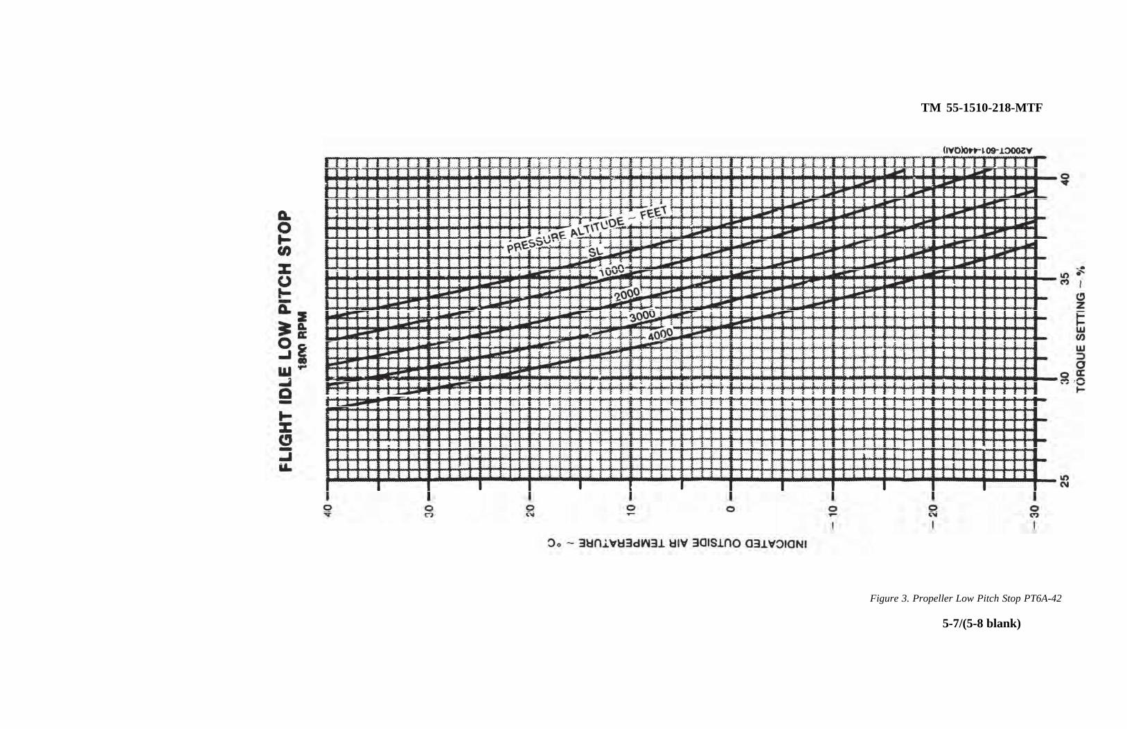
TM 55-1510-218-MTF
Figure 3. Propeller Low Pitch Stop PT6A-42
5-7/(5-8 blank)

TM 55-1510-218-MTF
THIS FIGURE HAS BEEN DELETED.
C1
Figure 4. Stall Speeds.
5-9/(5-10 blank)


TM 55-1510-218-MTF
Figure 5. Autofeather Time
5-11/(5-12 blank)

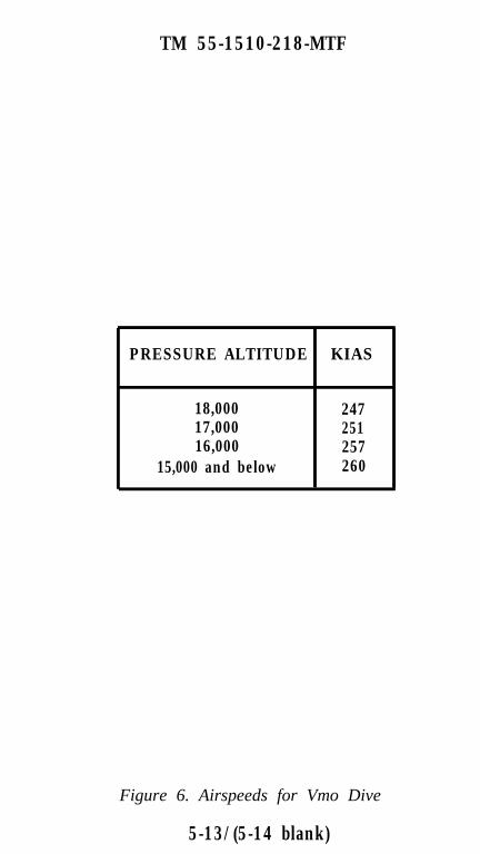
TM 55-1510-218-MTF
PRESSURE ALTITUDE KIAS
18,000 24717,000 25116,000 257
15,000 and below 260
Figure 6. Airspeeds for Vmo Dive
5-13/(5-14 blank)


TM 55-1510-218-MTF
Figure 7. Maximum Cruise Power, C-12C, PT6A-41
5-15/(5-16 blank)


TM 55-1510-218-MTF
Figure 8. Maximum Cruise Power, C-12D, PT6A-41
5-17/(5-18 blank)


TM 55-1510-218-MTF
Figure 9. Maximum Cruise Power, C-12F, PT6A-42
5-19/(5-20 blank)


TM 55-1510-218-MTF
Figure 10. Maximum Cruise Speed, C-12C, PT6A-41
5-21/(5-22 blank)


TM 55-1510-218-MTF
Figure 11. Maximum cruise Speed, C-12D, PT6A-41
5-23/(5-24 blank)

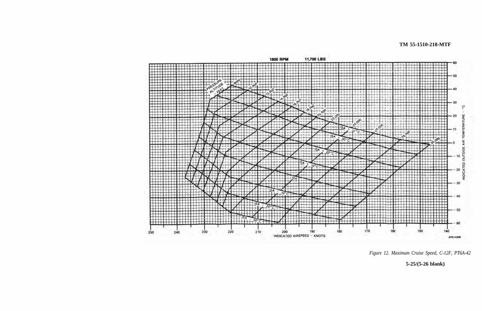
TM 55-1510-218-MTF
Figure 12. Maximum Cruise Speed, C-12F, PT6A-42
5-25/(5-26 blank)


TM 55-1510-218-MTF
1900 RPM - 175 KIASICE VANES RETRACTED, BLEED AIR OPEN
Figure 13. Engine Acceptance, C-12C, PT6A-41
5-27/(5-28 blank)


TM 55-1510-218-MTF
1900 RPM - 175 KIASICE VANCES RETRACTED, BLEED AIR OPEN
Figure 14. Engine Acceptance, C-12D, PT6A-41
5-29/(5-30 blank)


TM 55-1510-218-MTF
Figure 15. Engine Acceptance, C-12F. PT6A-42
5-31/(5-32 blank)

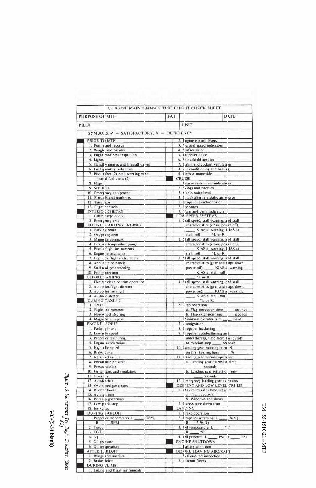
TM 55-1510-218-M
TF
Figure 16. Maintenance Test Flight Checksheet (Sheet
1of 2)
5-33/(5-34 blank)


TM
55-1510-218-MT
F
Figure 16. Maintenance Test Flight Checksheet (Sheet
2 of 2
5-35/(5-36 blank)


TM 55-2510-218-MTFRev
By Order of the Secretary of the Army:
Official:
CARL E. VUONOGeneral, United States Army
Chief of Staff
WILLIAM J. MEEHAN IIBrigadier General. United States Army
The Adjutant General
DISTRIBUTION:
To be distributed in accordance with DAForm 12-31, MTF Maintenance requirementsfor C-12C, Airplane, Cargo, and C-12D,Airplane, Cargo.


The Metric System and Equivalents

PIN: 05665 7-000

This fine document...
Was brought to you by me:
Liberated Manuals -- free army and government manuals
Why do I do it? I am tired of sleazy CD-ROM sellers, who take publicly available information, slap “watermarks” and other junk on it, and sell it. Those masters of search engine manipulation make sure that their sites that sell free information, come up first in search engines. They did not create it... They did not even scan it... Why should they get your money? Why are not letting you give those free manuals to your friends?
I am setting this document FREE. This document was made by the US Government and is NOT protected by Copyright. Feel free to share, republish, sell and so on.
I am not asking you for donations, fees or handouts. If you can, please provide a link to liberatedmanuals.com, so that free manuals come up first in search engines:
<A HREF=http://www.liberatedmanuals.com/>Free Military and Government Manuals</A>
– SincerelyIgor Chudovhttp://igor.chudov.com/
– Chicago Machinery Movers