tm-10-7200-200-13
TRANSCRIPT

8/2/2019 TM-10-7200-200-13
http://slidepdf.com/reader/full/tm-10-7200-200-13 1/49
TM 10-7200-200-13
TECHNICAL MANUAL
ORGANIZATIONAL AND DIRECT SUPPORT MAINTENANCE MANUAL
INCLUDING REPAIR PARTS AND SPECIAL TOOL LIST
CAN, GASOLINE, MILITARY; STEEL; 5-GALLON; FSN 7240-222-3088CAN, WATER, MILITARY; STEEL; 5-GALLON; FSN 7240-242-6153
CAN, WATER, MILITARY; ALUMINUM; 5-GALLON; FSN 7240-242-3767CAN, WATER, MILITARY; PLASTIC; 5-GALLON; FSN 7240-089-3827
CASE, MILITARY; WATER CAN; FSN 7240-125-9061
HEADQUARTERS, DEPARTMENT OF THE ARMYFEBRUARY 1974

8/2/2019 TM-10-7200-200-13
http://slidepdf.com/reader/full/tm-10-7200-200-13 2/49
WARNING
FIRE, HEALTH AND EXPLOSION HAZARDDEATH
or severe injury in personnel or damage to property
may result if personnel fail to observe safety precautions.
Open flames, heating stoves, electrical tools and apparatus,
and other flame or spark-generating equipment
must be prohibited.
Spills must be avoided or cleaned up immediately
when they occur.

8/2/2019 TM-10-7200-200-13
http://slidepdf.com/reader/full/tm-10-7200-200-13 3/49
TM 10-7200-200-13
C2
CHANGE
NO. 2
HEADQUARTERSDEPARTMENT OF THE ARMY
WASHINGTON, D.C.,30 January 1989
Operator, Organizational, and Direct Support
Maintenance Manual (Including Repair Parts
and Special Tools Lists)
CAN, GASOLINE, MILITARY; STEEL; 5-GALLON; FSN
7240-222-2088; CAN, WATER, MILITARY; 5-GALLON;
FSN 7240-242-6153; CAN, WATER, ALUMINUM;
5-GALLON; FSN 7240-242-3767; CAN, WATER
MILITARY; PLASTIC; 5-GALLON; FSN 7240-089-3827;
CASE, MILITARY WATER CAN; FSN 7240-125-9061
TM 10-7200-200-13, 15 February 1974, is changed as follows:
1. Remove and insert pages as indicated below. New or changed text materialis indicated by a vertical bar in the margin. An illustration change is indicated
by a miniature pointing hand.
Remove pages Insert pages
1-1 and 1-2 1-1 and 1-22-1 and 2-2 2-1 and 2-22-7/2-8 2-7/2-8
2. Retain this sheet in front of manual for reference purposes.
By Order of the Secretary of the Army:
Officia l:
CARL E. VUONO
General, United States Army
Chief of Staff
WILLIAM J . MEE HAN, II
Brigadier Gen era l, Unit ed S ta tes Arm y
The Adjutant General
DISTRIBUTION:
To be distributed in accordance with DA Form 12-25A, Operator, Unit, Direct
Support and General Support Maintenance requirements for Can, Gasoline, Steel5 Gal Cap; Water, Steel, Aluminum/Plastic, 5 Gal Cap (TM 10-7200-200-13)

8/2/2019 TM-10-7200-200-13
http://slidepdf.com/reader/full/tm-10-7200-200-13 4/49

8/2/2019 TM-10-7200-200-13
http://slidepdf.com/reader/full/tm-10-7200-200-13 5/49
TM 10-7200-200-13
C 1
CHANGE
No. 1
HEADQUARTERS
DEP ARTMENT OF THE ARMY
WA S H IN G TO N , DC 20 Augu st 1974
Operator, Organizational, and Direct SupportMaintenance Manual (Including Repair Parts
and Special Tools Lists)
CAN, GASOLINE, MILITARY; STEEL; 5-GALLON; FSN7240-222-2088; CAN, WATER, MILITARY; 5-GALLON;
FSN 7240-2424153; CAN, WATER, ALUMINUM;5-GALLON; FSN 7240-242-3767; CAN, WATER
MILITARY; PLASTIC; 5-GALLON; FSN 7240-089-3827;CASE, MILITARY WATER CAN; FSN 7240-1254061
TM 10-7200-200-13, 15 February 1974, is changed as follows:
1. Remove old pages and insert new pages as indicated below. New or changed material is indicated by a verticalbar in the margin of the page. Added or revised illustrations are indicated by a vertical bar adjacent to the
identification number. When an entire chapter, section or appendix is changed, the bar will be adjacent to thetitle only.
CREIGHTON W. ABRAMS
General, United States ArmyChief of Staff
Remo ve pag es In se rt pa ge s
i and ii i and ii
2-1 and 2-2 2-1 and 2-2
2-5 and 2-6 2-5 and 26
3-1 through 3-4 3-1 through 3-4
4-1 and 4-2 4-1 and 4-2
5-1 and 5-2 5-1 and 5-2
2. File this change sheet in the front of the publication for future reference.
By Order of the Secretary of the Army:
Official:VERNE L. BOWERS
Major General, United States ArmyThe Adjutant General
Distr ibut ion:To be distributed in accordance with DA Form 12-25A (qty rqr block no, 154), organizational maintenance
requirements for Petroleum Distribution.

8/2/2019 TM-10-7200-200-13
http://slidepdf.com/reader/full/tm-10-7200-200-13 6/49

8/2/2019 TM-10-7200-200-13
http://slidepdf.com/reader/full/tm-10-7200-200-13 7/49
*TM 10-7200-200-13
TECHNICAL M A N U A L HEADQUARTERS
DEPARTMENT OF THE ARMYNo. 10-7200-200-13 WASHINGTON , D.C., 15 February 1974
Operator, Organizational and Direct Support Maintenance Manual
Including Repair Parts and Special Tool List
CHAPTER 1.
Section I.
II.III.
CHAPTER 2
Section I.
II.
III.
IV.
V.
VI.
CHAPTER 3.
Section I.
II.
III.
IV.
V.
VI.
CHAPTER 4.
Section I.
I I .
III.
IV.
V.
VI.
CHAPTER 5.
Section I.
II.
III.
IV.
V.
CHAPTER 6.Section I.
II.III.
IV.
V.
VI.
APPENDIX A .
CAN, GASOLINE MILITARY; STEEL; 5-GALLON;FSN 7240-222-2088 CAN, WATER MILITARY; STEEL; 5-GALLON;
FSN 7240-242-6153: CAN, WATER, MILITARY; ALUMINUM;5-GALLON; FSN 7240-242-3767: CAN, WATER, MILITARY; PLASTIC;
5-GALLON; FSN 7240-089-3627: CASEMILITARY WATER CAN; FSN 7240-125-9061
Current as of 10 October 1973 Paragraph Page
INTRODUCTION
Genera l . . . . . . . . . . . . . . . . . . . . . . . . . . . . . . . . . . . . . . . . . . . . . . . . . . 1-1 — 1-5 1-1
Maintenance Allocation Chart . . . . . . . . . . . . . . . . . . . . . . . . . . . . . . . . . . . . . . . . . . . . . 1-6 — 1-8 1-1 — 1-2
Organizational and Direct Support Maintenance Repair Parts and Special
Tools List . . . . . . . . . . . . . . . . . . . . . . . . . . . . . . . . . . . . . . . . . . . . . . . . . . . . . . . . . . . . . . . . . . . . . . . . . . . 1-9 — 1-13 1-2 —1-4
CAN, GASOLINE, MILITARY; STEEL; 5-GALLON
Descri ption and Tabulated Data . . . . . . . . . . . . . . . . . . . . . . . . . . . . . . . . . . . . . . . . . . . . . . . . . . . . . . . . 2 - 1 , 2 - 2 2 - 1
Operator/Crew Maintenance . . . . . . . . . . . . . . . . . . . . . . . . . . . . . . . . . . . . . . . . . . . . . . . . . . . . . . . . . . . . 2 - 3 - 2 - 5 2 - l - 2 - 2
Organizat ional Maintenance . . . . . . . . . . . . . . . . . . . . . . . . . . . . . . . . . . . . . . . . . . . . . . . . . . . . . 2-6,2-7 2-3
Direct Suppor t Maintenance . . . . . . . . . . . . . . . . . . . . . . . . . . . . . . . . . . . . . . . . . . . . . . . . 2 - 8 , 2 - 9 2 - 5
Maintenance Allocation Chart . . . . . . . . . . . . . . . . . . . . . . . . . . . . . . . . . . . . . . . . . . . . . . . . . . . . . . .. . 2-6
Repa ir Pa rt s . . . . . . . . . . . . . . . . . . . . . . . . . . . . . . . . . . . . . . . . . . . . . . . . . . . . . . . . . . . . . . . . . . . . . . . . . . 2-7
CAN, WATER, MILITARY; STEEL; 5-GALLON
Descri ption and Tabulated Data . . . . . . . . . . . . . . . . . . . . . . . . . . . . . . . . . . . . . . . . . . . . . . . . . . . . . . . . 3 - 1 , 3 - 2 3 - 1
Operator/Crew Maintenance . . . . . . . . . . . . . . . . . . . . . . . . . . . . . . . . . . . . . . . . . . . . . . . . . . . . . . . . . . . . 3 - 3–3- 5 3 - 2
Organizat ional Maintenance . . . . . . . . . . . . . . . . . . . . . . . . . . . . . . . . . . . . . . . . . . . . . . . . . . . . . . . . . . . . 3-6,3-7 3-2
Direct Suppor t Maintenance . . . . . . . . . . . . . . . . . . . . . . . . . . . . . . . . . . . . . . . . . . . . . . . . . . . . . . . . . . . . 3 - 8 , 3 - 9 3 - 3
Maintenance Alloca tion Chart . . . . . . . . . . . . . . . . . . . . . . . . . . . . . . . . . . . . . . . . . . . . . . . . . . . . . . . . . . 3-4
Repair Parts . . . . . . . . . . . . . . . . . . . . . . . . . . . . . . . . . . . . . . . . . . . . . . . . . . . . . . . . . . . . . . . . . . . . . . . . . . 3-5
CAN, WATER, MILITARY; ALUMINUM; 5-CALLON
Description and Tabulated Data . . . . . . . . . . . . . . . . . . . . . . . . . . . . . . . . . . . . . . . . . . . . . . . . . . . . . . . . 4-1, 4-2 4-1
Operator/Crew Maintenance . . . . . . . . . . . . . . . . . . . . . . . . . . . . . . . . . . . . . . . . . . . . . . . . . . . . . . . . . . . . 4-3 – 4-5 4-1
Organizational Maintenance . . . . . . . . . . . . . . . . . . . . . . . . . . . . . . . . . . . . . . . . . . . . . . . . . . . . . . . . . . . . 4-6 , 4-7 4- 2
Direct Suppor t Maintenance . . . . . . . . . . . . . . . . . . . . . . . . . . . . . . . . . . . . . . . . . . . . . . . . . . . . . . . . . . . . 4- 8, 4-9 4-2
MaintenanceAllocationChart . . . . . . . . . . . . . . . . . . . . . . . . . . . . . . . . . . . . . . . . . . . . . . . . . . . . . . . . . . 4-3
Rep air Par ts . . . . . . . . . . . . . . . . . . . . . . . . . . . . . . . . . . . . . . . . . . . . . . . . . . . . . . . . . . . . . . . . . . . . . . . . . . 4-4
CAN, WATER, MILITARY; PLASTIC; 5-GALLON
Description and Tabulated Data . . . . . . . . . . . . . . . . . . . . . . . . . . . . . . . . . . . . . . . . . . . . . . . . . . . . . . . . 5-1, 5-2 5-1
Operator/Crew Maintenance . . . . . . . . . . . . . . . . . . . . . . . . . . . . . . . . . . . . . . . . . . . . . . . . . . . . . . . . . . . . 5-3 – 5-5 5-1
Organizat ional Maintenance . . . . . . . . . . . . . . . . . . . . . . . . . . . . . . . . . . . . . . . . . . . . . . . . . . . . . . . . . . . . 5-6 , 5-7 5- 2
Maintenance Allocation Chart . . . . . . . . . . . . . . . . . . . . . . . . . . . . . . . . . . . . . . . . . . . . . . . . . . . . . . . . . . 5-2
Repair Parts . . . . . . . . . . . . . . . . . . . . . . . . . . . . . . . . . . . . . . . . . . . . . . . . . . . . . . . . . . . . . . . . . . . . . . . . . . 5-3
CASE, MILITARY WATER CAN
Descri ption and Tabulated Data . . . . . . . . . . . . . . . . . . . . . . . . . . . . . . . . . . . . . . . . . . . . . . . . . . . . . . . . 6 - 1 , 6 - 2 6 - 1
Operator/Crew Maintenance . . . . . . . . . . . . . . . . . . . . . . . . . . . . . . . . . . . . . . . . . . . . . . . . . . . . . . . . . . . . 6 - 3 , 6 - 5 6 - 1
Organizat ional Maintenance . . . . . . . . . . . . . . . . . . . . . . . . . . . . . . . . . . . . . . . . . . . . . . . . . . . . . . . . . . . . 6 - 6 , 6 - 7 6 - 2
Direct Support Maintenance . . . . . . . . . . . . . . . . . . . . . . . . . . . . . . . . . . . . . . . . . . . . . . . . . . . . . . . . . . . . 6 - 8 , 6 -9 6 - 2–6-3
Maintenance Allocation Chart . . . . . . . . . . . . . . . . . . . . . . . . . . . . . . . . . . . . . . . . . . . . . . . . . . . . . . . . . . 6-7
Repa ir Pa rt s . . . . . . . . . . . . . . . . . . . . . . . . . . . . . . . . . . . . . . . . . . . . . . . . . . . . . . . . . . . . . . . . . . . . . . . . . . 6-8
R E FE R EN C ES . .. . . . . . . . . . . . . . . . . . . . . . . . . . . . . . . . . . . . . . . . . . . . . . . . . . . . . . . . . . . . . . . A-1
Change 1 i

8/2/2019 TM-10-7200-200-13
http://slidepdf.com/reader/full/tm-10-7200-200-13 8/49
TM 10-7200-200-13
LIST OF ILLUSTRATIONS
Numbe r Page
2-1
2-2
2-3
2-4
3-1
4-1
5-1
6-1
6-2
6-3
6-4
6-5
6-6
Title
Gasoline can, military, 5-gallon
Cleaning the S-gallon can using the cleaning machine
Flow diagram for improvised can cleaning machine
Improvised can cleaning machine
Water can, steel .5-gallon
Water can, aluminum, 5-gallon
Water can, plastic, 5-gallon
Case, military water can
Base assembly for case
Cutaway view of slide fastener
Reinforcement webbing on Case
Carrying strap on case
Case, military water can and components
2-1
2-3
2-4
2-5
3-14-2
5-1
6-1
6-3
6-4
6-5
6-6
6-7
i i Change 1

8/2/2019 TM-10-7200-200-13
http://slidepdf.com/reader/full/tm-10-7200-200-13 9/49
CHAPTER 1INTRODUCTION
TM 10-7200-200-13
Section I. GENERAL
1-1. Scope
This manu al is for your use in mainta ining the five
gallon militar y can s an d can case.
1-2. Maintenance Forms and RecordsMaintenance forms and records that you are required
to use a re explain ed in DA PAM 738-750.
1-3. Destruction of Army Materiel toPrevent Enemy Use
Procedures to be used for destruction of the equip-
men t to prevent enemy use a re in TM 750-244-3.
1-4. Administrative Storage
a. General. For administrative storage instruc-tions , refer t o TM 740-90-1.
b. Gasoline Cans. For additional storage instru c-
tions for ga soline cans, r efer t o TM 743-200 an d TB
740-97-2.
C . Water Cans. To prepare the 5-gallon water cans.
for storage, remove the cap and turn upside down ina clean dry area. Allow the cans to drain and air dry
completely. After the cans are completely dry,
reinstall the caps and store the cans upright in a clean
dry area.
d. Stacking Instructions. For stacking instruc-
tions of the 5-gallon cans, refer to TM 10-1101.
1-5. Reporting of Errors
You can imp rove th is man ua l by calling at ten tion to
errors and by recommending improvements, using
DA Form 2028 (Recomm ended Ch an ges to Pu blica-
tions) or by a letter, and mail directly to the Com-mander, U.S. Army Troop Support Command, ATTN:
AMSTR-MCTS 4300 Goodfellow Boulevard, St.
Louis, Missouri 63120-1798. A reply will be furnish-
ed direct t o you.
Section Il. MAINTENANCE ALLOCATION CHART1-6. General
a. This section provides a general explanation of
all maintena nce and repair functions a uth orized at
various maintenance levels.
b. Part I, Section V of Chapters 2,3,4, and 6 and
Section IV of Chapter 5 designate overa ll responsibili-
ty for t he per form an ce of ma inten an ce functions on
the identified end item or component. The implemen-
tat ion of the ma intenan ce functions u pon t he end item
or component will be consistent with the assigned
maintenance functions.
c. Par t I I conta ins supplemental inst ructions, ex-
planatory notes, and/or illustrations required for a
particular maintenance function.
1-7. Explanation of Columns in Section
V of Chapters 2, 3, 4, and 6 and
Section IV of Chapter 5
a. Group Number, Column (l). The assembly group
is a nu merical group assigned to each assembly in a
top down breakdown sequence. The applicable
as sem bly g roups a re l i s t ed on the M A C in
disassembly sequence beginning with the f irst
assembly removed in a top down disassembly
b. Assembly Group, Colum n (2). This column con-
tains a brief description of the components of each
assembly group.
c. Maintenan ce Fu ncti ons, Colum n (3). This col-
umn lists the various maintenance functions (A
through K). The lowest maintenance level authorizedto perform these functions are indicated by a symbol
in th e appropria te column . The symbol designat ions
for t he var ious m aint ena nce levels are a s follows:
C—Operator or crew
O—Organizational maintenance
F—Direct support m aintena nce
H—General support maintenance
D—Depot maintenance
The ma inten an ce functions a re defined as follows:
A—Inspect: To determin e serviceability of an item
by comparing its physical, mechanical, and electricalchar acteristics with esta blished sta ndar ds.
B– T est: To verify serviceability y and to detect elec-
trical or mechanical failure by use of test equipment.
C–S ervice: To clean, to preser ve, to charge, an d to
add fuel, lubrican ts, cooling agent s, and a ir.
D— Adju st : To rectify to the extent necessary to
bring into proper operating r ange.sequence.
Change 2 1-1

8/2/2019 TM-10-7200-200-13
http://slidepdf.com/reader/full/tm-10-7200-200-13 10/49
E–A1ine: To adjust specified var iable elements of
an item to bring to optimum performance.
F–Calibrate: To determine the corrections to be
made in the read in~m of ins t ruments o r t e s t
equipment used in precise measurement. Consists of
the comparison of two instruments, one of which is a
cert ified stan dar d of known a ccur acy, to detect an d
adjust any discrepancy in the accuracy of the
instrument beining compared with the certified stan-
dard.
G–Install: To set up for use in an operationalenvironment such as an emplacement , s i te , or
vehicle.
H–Replace: To replace unserviceable items with
serviceable like items.
I – Repair: Those maintenance operations neces-
sary to restore an item to serviceable condition
th rough corr ection of ma teria l dam age or a specific
failur e. Repair m ay be a ccomplished at each level of
main tenance .
J — Ov erh au l: Normally, the highest degree of
maintenance performed by the Army in order to
minimize time work in process is consistent with
quality a nd economy of opera tion. It consists of tha t
maintenance necessary to res tore an i tem to
completely serviceable condition as prescribed by
ma intena nce stan dar ds in technical publicat ions for
each item of equipment. Overhaul normally does not
retu rn an item to like new, zero mileage, or zero hour
c o n d i t i o n .
K— Rebu i ld : The highest degree of mater ie l
maintenance. It consists of restoring equipment as
nearly as possible to new condition in accordance
with original manufacturing standards. Rebuild is
performed only when required by operational con-
siderations or other paramount factors and then-
only at the depot maintenance level. Rebuild reduces
to zero the hours or miles the equipment or
component thereof, has been in use.
d. Tools and Equipm ent, Colum n (b). This colum n
is provided for referencing by code the special tools
and t est equipment required to perform t he maint e-
nance functions.
e. Rem arks, Colum n (5). Th is column is provided
for referencing by code the remarks (Part
pertinent to the maintena nce functions.
1-8. Explanation of Columns in Section
V (Part II)
a. Reference Code. This column consists of
letter separated by a dash, both of which
II )
two
a r e
references to Part I. The first letter references
column (5) and the second le t ter references a
maintenance function, column (3), A through K.
b. Remarks. This column lists information perti-
nent to the maintenance function being performed,
as indicated on the MAC, Part I.
Section Ill. ORGANIZATIONAL AND DIRECT SUPPORT MAINTENANCEREPAIR PARTS AND SPECiAL TOOLS LIST
1-9. Scope
a. This section lists repair parts, special tools, test,and support equipment required for the perfor-
mance of organizational, direct support, general
support, and depot maintenance of the five gallon
can.
b. Repair pa rts listed represent those auth orized
for use at indicated maintenance levels and will be
requisitioned on an “as required” basis until stock-
age is justified by demand in accordance with A R
710-2.
1-10. General
This Repair Parts and Special Tools List is divided
into the following sections:
a. Prescribed Load Allowan ce List. (Not applicable).
b. Repair Parts List - Section VI. A list of repair
parts authorized for the performance of mainte-
nance. The list also includes parts which must be
removed for replacement of the authorized parts.
Parts lists are composed of assembly groups in
ascending numerical sequence, with the parts in
each group l is ted in f igure and i tem numbersequence.
1-11. Explanation of Columns
The following provides an explanation of columns
found in the tabulated listings in Sections V and VI.
a. Illustration. This column is divided as follows:
(1) Figure Number.. Indicates the figure number
of the illustration on which the item is shown.
(2) It em N um ber . Indicates the callout number
used to reference the item on the illustration.
b. S ource, Main tenance, and Recoverability Codes
(SMR). The S MR code is a five lett er code composed
of three parts consisting of a two (2) position source
code, a two (2) position maintenance code, and a one
(1) position recoverability code. Support items listed
in this RPSTL assigned maintenance and recovera-
bility codes and no source code can be requisitioned,
with justification, through normal supply channels
by use of the man ufacturer ’s code and pa rt n um ber
1-2

8/2/2019 TM-10-7200-200-13
http://slidepdf.com/reader/full/tm-10-7200-200-13 11/49
Such support items are NOT normally stocked.
(1) S ource code. Indicates t he ma nn er of acquir-
ing support i tems for maintenance, repair , or
overhaul of end items. Source codes are entered in
the fi rst and second positions as follows:
Code
PA
P B
PC
PD
P E
PF
PG
KD
KF
KB
MO
MF
MH
MD
AO
AF
AH
AD
XA
XB
XC
XD
Def in it ion
Item procured and stocked for anticipated or known
usage.
Item procured and stocked for insurance purposes be-
cause essentiality dictates that a minimum quantity
be available in th e supply system.
Item pr ocured and stocked an d which otherwise would
be coded PA except th at it is deteriorat ive in n atu re.
Support item, excluding support equipment, procured
for initial issue or outfitting and stocked only for sub-
sequent or additional initial issues or outfitting. NOT
subject to au tomatic replenishment.
Support equipmen t pr ocured a nd st ocked for initial issue
or outfitting to specified maint enan ce repair activities.
Support equipment which will not be stocked but which
will be centrally procured on deman d.
Item procured and stocked to provide for sustained sup-
port for life of the equipm ent. It is a pplied to an item
peculiar to the equipment which, because of probablediscontinuance or shutdowm of production facilities,
would prove un economical to reproduce at a later date.
An item of depot overhaul/repair kit and not purchased
separately.
An item of a maintenance kit and not purchased sep-
arately.
Item included in both a depot overhaul/repair kit and a
maintenance kit.
Item to be manufactured or fabricated at organizational
level.
Item to be manufactured or fabricated at direct support
maintenance level.
Item to be manufactured or fabricated at general sup-
port maint enan ce level.
Item to be manufactured or fabricated at depot mainte-nance level.
Item t o be assembled at organizational level.
Item to be assembled at direct support maintenance
level.
Item to be assembled at general support maintenance
level.
Item to be assembled at depot ma intena nce level.
Item is N OT procured or st ocked because th e require-
ment s for t he item will result in r eplacement of the
next higher assembly.
Item NOT procured or stocked. If not available through
salvage, requ isition.
Installation drawing, diagram, instruction sheet, or
A
field service drawing that is identified by manufac-
turer ’s part num ber.low mortality item th at is n ot stocked. When requ ired,
items will be requested and provided through normal
supply chan nels.
NOTE
Cannibalization or salvage may be used as a
source of supply for any items coded above except
those coded XA and support items restricted by
AR 700-42.
(2) Mai ntenan ce codes . The maintenance code
entered in the third position indicates the lowest
maintenance level authorized to remove, replace,
and use th e item. The maintena nce code entered in
the fou rt h position indicates whether the item is to be
repaired and identifies the lowest maintenance level
with the capability to perform complete repair (i.e.,
all authorized maintenance functions). When a
maint enance code is not used in t he fou rt h position, a
dash (-) will be entered.
Code Appl i cat i on/ Explanat i on
O Item is removed, replaced, used (third position), or com-
plete repair (fourth position) at the organizational
level.
F Item is removed, replaced, used (third position), or com-
plete repair (fourth position ) at the direct support
maint enan ce level.
H Item is removed, replaced, used (third position) or com-
plete repair (fourth position) at the general support
maint enan ce level.
D Item is removed, replaced, used (third position) or com-
plete repair (fourth position) at th e depot maintena nce
level.
L Repair rest ricted to designated specialized repa ir activity
(fourth position ).
Z Non-repairable. No repairs aut horized (fourth position).
B No repair is authorized. The item may be reconditioned
by adjusting, lubricating, etc., at the user level. No
parts or special tools are procured for maintenance of
this item (fourth position).
(3) Recovera bi li ty code. The recoverability code
entered in the fifth position indicates the disposition
action on unserviceable items.
Code Definit ion
Z Non-repairable item. When unserviceable, condemn an
dispose at the level indicated in position thr ee (3).
O Repairable item. When uneconomically repairable, con
demn a nd dispose at organizational level.
F Re pa ir a ble it em . Wh en un econ om ica lly r ep air a ble , con
demn a nd dispose at direct support level.
H Repairable item. When uneconomically repairable, con
demn a nd dispose at general support level.
D Repairable item. When beyond lower level repair cap
ability, return to depot. Condemnation and disposa
not authorized below depot level.
L Repairable item. Repair, condemn ation, and disposal no
authorized below depot/specialized repair activity
level.
A Item requires special han dling or condemnat ion pr oce
dures because of specific reasons (i.e., precious meta
content, high dollar value, critical material, or haz
ardous material).
c. Federal Stock Number. Indicates the Federal
stock nu mber a ssigned to the item and will be used
for requisitioning purposes.
d. Part Number. Indicates the primary number
used by th e man ufactur er which contr ols th e design
1-3

8/2/2019 TM-10-7200-200-13
http://slidepdf.com/reader/full/tm-10-7200-200-13 12/49
and characteristics of the item by means of its
engineering drawings, specifications standards, and
inspection requirements to identify an item or range
of items .NOTE
When a stock numbered item is requisitioned, the
repair part received may have a different part
number than the part being replaced.
e. Federal S upp ly Code for Manu facturer (FS CM).
The FSCM is a 5-digit numeric code listed in SB70842 which is used to identify the manufacturer,
distributor, or Government agency, etc.
f. Descript ion . Indicates the Federal item name
and, if required, a minimum description to identify
the item. Items that are included in kits and sets are
listed below the n ame of the kit or set with quan tity
of each item in the kit or set indicated in front of the
item name.
g. Unit of Measure (U/ M). Indicates the standard or
basic quantity by which the listed item is used
in performing the actual maintenance function. This
measu re is expressed by a two-character a lphabeti-
cal abbreviation, e.g., ea, in., pr, etc., and is the basis
used to indicate quanti t ies and al lowances in
subsequent column s.
h. Quantity Incorporated. in Unit. Indicates the
quan tity of the item used in th e breakout shown on
the illustration figure, which is prepared for an
assem bly group or a n a ssembly. A “V” app ear ing in
this column in lieu of a quantity indicates that no
specific quantity is applicable.
etc.
1-12. Special Information
e.g., shims, s pacers,
a. The basis of issue for authorized special tools,test, and support equipment is the number of end
items of equipment supported and the number of
maintenance personnel allocated to perform the
required maintenance operations.
b. Parts which require manufacture or assembly of
a maintenance level higher than that authorized for
installation will indicate in the source column the
higher maintenance level.
c. Repair parts ki ts and gasket sets appear as th e
last ent ries in th e repair par ts listing for t he group or
assembly to which they apply.
1-13. How to Locate Repair PartsDue to the limited num ber of repair pa rts, deta iled
instructions on how to locate repair parts are not
required. To locate repair part s refer to th e Repair
Parts Listing in each chapter.
1-4

8/2/2019 TM-10-7200-200-13
http://slidepdf.com/reader/full/tm-10-7200-200-13 13/49
TM 10-7200-200-13
CHAPTER 2CAN, GASOLINE, MILITARY; STEEL; 5-GALLON
Section I. DESCRIPTION AND TABULATED DATA
2-1. Description
The 5-gallon steel military gasoline can (fig. 2-1) iscovered by specification MIL-C-1283D. The can is in-
tended for use in transporting liquid fuels by comrner-
cial common carriers, military motor vehicles, aircraft
or vessel transportation, and for storaging and
dispens ing of liquid fuels.
2-2. Tabulated Data
a. Dimensions and Weight.
Length . . . . . . . . . . . . . . . . . . . . . . . . . .13¾ inches
Width . . . . . . . . . . . . . . . . . . . . . . . . . . . . . . . . 6¾ in ches
Heigh t . . . . . . . . . . . . . . . . . . . . . . . . . . .18¾ in chesWeight (empty) . . . . . . . . . . . . . . . . . . . . .10.5 1bs.
Weight (average wt. wh en filled
w/gasoline) . . . . . . . . . . . . . . . . . . . ..41.0 lbs.
b. Capacities.
Liqu id . . . . . . . . . . . . . . . . . . . . . . . . . . . 5.05 ga l.
Cubage . . . . . . . . . . . . . . . . . . . . . . . . . . l cu. ft.
Figure 2-1. Gasoline can, military, 5 gallon.
Section II.
2-3. Lubrication InstructionsThe five gallon gasoline can does
lubrication.
OPERATOR/CREW MAINTENANCE
2-4. Preventive Maintenance Servicesnot requi re The necessary preventive maintenance checks and
services to be performed at regularly scheduled
Change 2 2-1

8/2/2019 TM-10-7200-200-13
http://slidepdf.com/reader/full/tm-10-7200-200-13 14/49
TM 10-7200-200-13
intervals are listed in table 2-1.
2-5. Inspectionproviding the can is not ruptured and the dents do
not impair st acking.a. Condition of Paint. Check each can for condition (2) A can with dents that have caused a rupture
of paint and indicate whether repainting is required. anywhere in the can is not repairable. A can thatb. Dents. Check each can for dented condition. does not stack properly due to distortion caused by
(1) A can may be used without repairs to dents dents is nonrepaira ble.
Table 2-1. PREVENTIVE MAINTENANCE CHECKS AND SERVICES
c. Contamination. Check interior of each can for
general cleanliness and presence of contaminants.
(1) Can cont ainin g r emovable cont am inan ts
should be cleaned th oroughly before being p laced in
use.
(2) Can s cont ainin g a residue of asph alt, ta r, or
s imi lar subs tance tha t cannot be removed are
classified as nonrepairable.
d. Rust. Check exterior and interior of can for
presen ce of ru st.
(1) Cans with moderate exterior rusting are
repairable if rust can be removed by buffing or
sandblasting without weakening the metal. The
interior of cans must be free of loose rust before they
are used.
(2) Cans with excessive interior rusting that
cannot be r emoved by solvent or caust ic wash ing or
cans with excessive exterior rusting are classified as
n o n r e p a i r a b l e .
e. Holes. Check each can car efully for presen ce of
holes. A hole, rip, or rupture anywhere in the can,
except th e han dle assembly, renders it nonrepaira-
ble .
f. Flange. Check condition of flange on each can.
Make sur e the flange is securely seated in t he hea d
and that the flange threads are in good condition.
Cans with crossed, stripped, rusted, or worn flange
thr eads a re classified as nonrepairable.
g. Closure and Gasket. Check each can for missing
or defective closure and/or gasket and indicate repair
when required.
h. Vent T ube. Check condition of vent tube in each
can. Clogged vent tubes should be cleaned. Cans withbroken or missing vent tubes may be used only in an
emergency.
i. Handle Asseembly. Check condition of handle
assembly. Cans with holes, dents, or rips in the
handles are serviceable if they cart be carried
without injury to hands. When such damage must be
repa ired before cans can be carr ied safely, indicat e
repairs required.
2-2 Change 1

8/2/2019 TM-10-7200-200-13
http://slidepdf.com/reader/full/tm-10-7200-200-13 15/49
Section Ill. ORGANIZATIONAL MAINTENANCE
2-6. Special Tools and Equipment
The 5-gallon gasoline can does not require special
tools, parts, or equipment.
2-7. Cleaning and Repair
Following the initial inspection, assemble the con-
taminated cans near the cleaning machine. Place
each filler plug under the handle assembly so that
the plug will not get in th e way during th e cleaning
operation.
a. Fuel Can Cleaning Mach in e Operation .
(1) In a four-man cleaning operation, two men
operate the cleaning machines and two men support
the operators. One man operates each cleaning
assembly. The t wo support m en su pply the operator
with cans t o be cleaned an d move the clean can s to
the clean can area. The operator staggers the cans inthe cradles (fig. 2-2) so that the cleaning process is
continuous. Each can passes through a 40-second
flushing cycle and a 6-second draining cycle before it
is removed from the cradle.
Figure 2-2. Cleaning 5-gallon cans using a cleaning machine.
(2) In a two-man cleaning operation, the rate of
production is relatively slow. One man operates both
cleaning assemblies, and the second man supplies
conta minat ed can s to the operat or a nd removes the
clean cans from the area.
(3) The can should be inspected with an explosion-proof flashlight or extension light. The interior of
each can must be clean and free from rust. If
sediment remains in the cans, the cans should be
recleaned. Only one clean ing ass embly will be used
during the recleaning process. The other cleaning
assembly will be closed to achieve total pressure.
Flush the cans 2-or 3-minutes a s required. If cans are
still not properly clean, they will be routed through
channels for reclamation or salvage.
(4) All damaged or missing parts, such as the
closure assembly (fig. 2-1) and gasket (6), will be
replaced. Filler plugs will be inserted in the cans andt ightened, unless the cans are to be used im-
mediately. If cans are to be stored temporarily, plugs
will be ha nd t ightened. If they ar e to be stored for a
long period, plugs will be wrench tightened.
b. Improvised Can Cleaning Machine Operation.
The procedure for cleaning cans with the improvised
can cleaning ma chine (figs. 2-3 an d 2-4) is similar to
2-3

8/2/2019 TM-10-7200-200-13
http://slidepdf.com/reader/full/tm-10-7200-200-13 16/49
the procedure in subparagraph a above. When using to cover all the spray outlets. Flush the can for 40
the improvised machine, however, the operation seconds and drain them for 6 seconds. After draining,
cannot be staggered unless the machine is equipped remove the cans from the rack to make way for a new
with a multiple valve system. When a multiple valve group of cans.
system is not provided, place enough cans in the rack
Figure 2-3 Flow diagram for improvised can cleaning machine.
c. Emergency Can Cleaning Method. When the can be employed. The cans can be cleaned by sloshing
cleaning machine is not available and improvised solvent a bout them and allowing th em to drain.
method is impracticable, an emergency method can
2-4

8/2/2019 TM-10-7200-200-13
http://slidepdf.com/reader/full/tm-10-7200-200-13 17/49
TM 10-7200-200-13
ME 7200.200-1 3/2-4
Figure 2-4. Improvised can cleaning machine.Section IV. DIRECT SUPPORT MAINTENANCE
Repair Parts, Special Tools and Equip-ment
Special Tools and Equipment. The five g a l l o n
2-8.
a.
gasoline can does not require special tools and
equipment.
b. Repair Parts. Repair parts issued with or
authorized for the five gallon gasoline can are listed
in the Repair Parts List, Section VI.
2-9. Refinishing
WARNING
Cans must be gas free. To make cans safe
for handling, they must be gas freed by
flushing with water or steam, and draining.
Air under pressure must never be admitted
into a can until it is gas free.
a . R e m o v i n g D e n t s . No attempt will be made to
remove dents from cans. Dents in cans are accepta-
ble, providing the cans are not ruptured and the
dents a re n ot so severe a s to impair sta cking.
b. Cleaning Exterior. Flanges and plugs, especially
threads and gasket sea ts , must be thoroughly
cleaned. Clean flanges and plugs with a solvent,
P-D-680, and a brush to remove all corrosion and
other foreign matter. All gaskets should be removed
before cans are cleaned. All loose paint, rust, grease,
and other foreign matter will be removed from the
exterior of the can. This will be done by chemical or
mechan ical means.
(1) Chemical cleanin g. When cans are cleaned
chemically, they will be clean ed with solut ions t ha t
do not dissolve or attack steel. Rust maybe removed
with solutions containing diluted phosphoric acid.
The condit ions of use; t ime, temperature, and
concentration; of phosphoric-acid solutions will be
such as to minimize dama ge to the steel.
(2) Mechan ical cleanin g. Before a can is cleaned
Change 1 2-5
8/2/2019 TM-10-7200-200-13
http://slidepdf.com/reader/full/tm-10-7200-200-13 18/49
TM 10-7200-200-13
mechanically, it should be free of excessive grease
and oil. Mechanical cleaning methods may include
buffing or blasting. Buffing consistsof cleaning bqy
means of rotating brushes or rotating the can
against con verging brushes. Blasting consists of
pressure spra y ing the can with sand or grit or similar
material. The operator must determine the extent to
which blasting is feasible without excessive metal
removal.c. Cleaning Interior. Before cans undergo further
reconditioning, clogged vent tubes will be cleaned by
prodding or by applying air pressure. Unlined cans
will be thoroughly cleaned by washing with a strong,
hot, alkali solution or a suitable detergent solution.
This process will be continued until all loose rust,
scale, or other foreign matter is removed. If the cans
are lined and the interior coating is broken, blistered,
or loose, the interior linings must be stripped
chemically and the cans must be cleaned thoroughly.
If more than very light rust remains after cleaning of
either lined or unlined cans, the rust should be
removed with solutions containing dilute phosphoric
ac id .
d. Rinsing and Drying. Each can will be ade-
quately rinsed to remove cleaning solutions. Clean
hot water, maintained at a temperature of 150F. will
be used for rinsin g. After t he can is rinsed, it will be
siphoned free of excess water and heated for a period
sufficient to vaporize all remaining moisture. The
can will be purged with air, preferably hot, to
eliminate all excess vapor. It must be above room
temperature and free” of all moisture and residue at
the completion of drying. Completion of drying can be
determined by a simple test. Hold a cool glass overth e can opening; if condensa tion form s on th e glass,
the can is not sufficiently dry.
e. Replacing Part s. Plugs for can s should be fitted
with new synth etic rubber gaskets. Closure assem-
bly should be replaced as necessary.
f. Leak Testing. Before the cans are painted or
tr eat ed with pr eservat ive oil, th ey will be test ed for
leaks. Cans with leaks in the body of the can will be
scrapped. The presence of leaks can be determined
by either of th e following test s:
(1) Water tank test. Cans are subjected to internal
air pressure and completely submerged in cleanwater. Air bubbles emitted from cans indicate the
presen ce and locat ion of leak s.
(2) Air pressurre tes t. Cans are subjected to
int ern al a ir pr essu re of 7-to 9-psi for a per iod of 45
seconds. A drop in air pressure, as indicated on an
accurate pressure gage during the test period, shows
the presence of leaks.
g. Repairing Leaky Can. Cans with leaks in the
body will be scrapped. Closure assembly leaks will be
r e p a i r e d .
h. Painting Exterior. After cans have been
repaired, thoroughly cleaned, leak tested, dried, andru st freed, exteriors will be pain ted with one coat of
rust-inhibiting enamel. Before cans are painted,
plugs must be inserted and hand tightened. Paint
will be applied uniformly by spray. Cans will be either
heated to a temperature of 250°F and dried in a
suitable drying oven immediately after painting, or
baked at 250° F for 45 minutes or an equivalent
time-temperature cycle.
i. Prpreventing Interior rust. When cans have cooled,
remove th e plugs and spray t he int erior of each can
with preservative oil injected under pressure for
complete a tomizing. No excess spr ay will remain to
collect on the bottom. All plugs with gaskets in place,should be made wrench tight immediately after
preservative oil has been injected, All air lines used
for spraying preservative oil will be suitable trapped
to prevent condensate in t he cans.
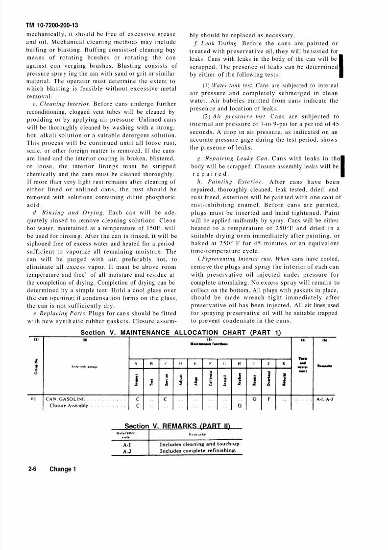
Section V. MAINTENANCE ALLOCATION CHART (PART 1)
Section V. REMARKS (PART II)
2-6 Change 1

8/2/2019 TM-10-7200-200-13
http://slidepdf.com/reader/full/tm-10-7200-200-13 19/49
Chapter 2
Section VI
Group 01
TM 10-7200-200-1
Change 2 2-7/(2-8 Blank)
1 6 0 - 9 6 8 - 9 4 - 2
7240-00-222-3088
7240-00-025-3377
5330-00-298-7165
7240-00-177-6154
5310-00-228-6638
7240-00-132-6433
7240-00-132-6431
13219E2670
3-3-47
MIL-G-432
13219E2600
00-8-1-161

8/2/2019 TM-10-7200-200-13
http://slidepdf.com/reader/full/tm-10-7200-200-13 20/49

8/2/2019 TM-10-7200-200-13
http://slidepdf.com/reader/full/tm-10-7200-200-13 21/49
TM 10-7200-200-13
CHAPTER 3CAN, WATER MILITARY; STEEL; 5-GALLON
Section I. DESCRIPTION AND TABULATED DATA
3-1. Description3-2 Tabulated Data
The 5-gallon steel military water can (fig. 3-1) isa. Dimensions and Weight.
covered by specification MIL-C13984. It is of steelLength . . . . . . . . . . . . . . . . . . . . . . . . . . . . . . . . . . . . . . . . 13¾ inches
Widthconstruction, fabricated by the continuous weld
. . . . . . . . . . . . . . . . . . . . . . . . . . . . . . . . . . . . . . . . . 65/8 inches
Height . . . . . . . . . . . . . . . . . . . . . . . . . . . . . . . . . . . . . . . . . 183/8 inches
method. The top, handle, and cover assembly Weight (empty) . . . . . . . . . . . . . . . . . . . . . . . . . . . . . . . . . 9.58 lbs.
comprise approximately 41/8 inches of the overallWeight (filledwithwater) . . . . . . . . . . . . . . . . . . . . . 51.28 lbs.
height Each can has a cover attached to a locking b. Capacities.
device which will provide a watertight seal when Liquid . . . . . . . . . . . . . . . . . . . . . . . . . . . . . . . . . . . . . .5.05 gal.
a f f i x e d in a closed position. Cubage . . . . . . . . . . . . . . . . . . . . . . . . . . . . . . . . . . . . . . . 1 cu. ft
Figure 3-1. Water can, steel, 5-gallon.
Change 1 3-1

8/2/2019 TM-10-7200-200-13
http://slidepdf.com/reader/full/tm-10-7200-200-13 22/49
TM 10-7200-200-13
Section Il.
3-3. Lubrication Instructions
The five gallon water can does not require lubrica-
tion.
3-4. Preventive Maintenance Services
The necessary preventive maintenance checks and
services to be performed at regularly scheduled
intervals ar e listed in ta ble 3-1.
3-5. Cleaning and Inspection
a. Inspection
(1) Inspect the can for leaks, dents, holes, and
other dama ge. Make su re t he can is free from leaks.
Check dented condition of can. Check the condition of
the flange on each can.
OPERATOR/CREW MAINTENANCE
(2) Inspect the interior of each can for cleanliness
and for the presence of contamination and rust. Rust
other than pin point rust is not permissible and
repainting t he inter ior is pr ohibited.
(3) Inspect the exterior of each can for the
condit ion of the pa int.b. Cleaning.
(1) Wash dirt, dust, grease, and other foreign
mat ter from the exterior of the cans with hot water ,
soap, and brush .
(2) Clean the interior of the can by immersing in
hot water containing a hand-dishwashing com-
pound, P-D410, and swishing until thoroughly clean.
Do not scour with steel wool.
(3) Rinse cans in clean boiling water, turn upside
down, a nd a llow to dry.
Table 3-1. PREVENTIVE MAINTENANCE CHECKS AND SERVICES
Section III. ORGANIZATIONAL MAINTENANCE
3-6. Special Tools and Equipment
The five gallon water can does not require special
tools, parts, or equipment.
3-7. Repair.
a. Nonmetallic Washer (Gasket). Re-cement loose
washers that are in good condition. Replace missingor defective wash ers with new ones (1, fig. 3-l). Use
only approved nontoxic cement (FSN 8040-273-8717).
b. Closure Assembly. Replace the closure assembly
when damaged.
(1) Lift locking lever cam (2) and open cover of
can.(2) File off peened end of hinge pin (3) securing
closure assembly (5) to the hinge brackets.
(3) Remove hinge pin (3) and washer (4). Replacewith new closure assembly.
(4) Replace pin and washer with new ones. Use ahammer to peen replacement h inge pin whi le
holding opposite end of pin in position with an other
ham mer or suitable tool.
3-2 Change 1

8/2/2019 TM-10-7200-200-13
http://slidepdf.com/reader/full/tm-10-7200-200-13 23/49
TM 10-4200-200-13
Section IV. DIRECT SUPPORT MAINTENANCE
3-8. Repair Parts, Special Tools and Equip-ment
a. Special Tools and Equipment. The 5-gallon
water can does not require special tools and
equ ipm en t .
b. Repair Parts. Repair par ts i ssued wi th or
aut horized for t he 5-gallon wat er can a re listed in th e
Repair Parts List, Section VI.
3-9. Refinishing
a. Removing Dents. No attempt will be made to
remove dents from cans. Dents in cans are accepta-
ble providing the cans are not ruptured and the
dents a re not so severe as to impair sta cking.
b. Cleaning Exterior. Flanges and plugs, especially
threads and gasket sea ts , must be thoroughly
cleaned. Clean flanges and plugs with a solvent,P-D-680, and a brush to remove all corrosion and
other foreign matter. All gaskets should be removed
before cans are cleaned. All loose paint, rust, grease,
an d other foreign mat ter will be removed from th e
exterior of the can. This will be done by chem ical or
mechanical mean s.
(1) Chemical cleaning. When cans are cleaned
chemically, they will be cleaned wit h solutions t ha t
do not dissolve or attack steel. Rust maybe removed
with solutions containing diluted phosphoric acid.
The condit ions of use; t ime, temperature, and
concentration; of phosphoric acid solutions will be
such as to minimize dama ge to the steel.
(2) Mechan ica l clean in g. Before a can is cleaned
mechanically, it should be free of excessive grease
and oil. Mechanical cleaning methods may include
buffing or blasting. Buffing consists of cleaning by
means of rotating brushes or rotating the can
against converging brushes. Blasting consists of
pressure spra ying the can with sand or grit or similar
material. The operator must determine the extent to
which blasting is feasible without excessive metal
removal.
c. Cleaning Interior. Cans will be thoroughly
cleaned by washing in hot water containing ahan d-dishwashing compound, P-D410. Repeat this
until all loose rust, scale, or other foreign matter is
removed. If rust other than pin-point of line (weld)
rust remains after cleaning, the can will be salvaged.
Rinse cans in clean boiling water, turn upside down,
an d allow to dry.
d. Rinsing and Drying. Each can will be ade-
quately rinsed to remove cleaning solutions Clean
hot water, maintained at temperature of 150°F., willbe used for rinsing. After the can is rinsed, it will be
siphoned free of excess water and heated for a period
sufficient to vaporize all remaining moisture. The
can will be purged with air, preferably hot, to
eliminate all excess vapor. It must be above room
tempera tur e and free of all moisture a nd residue at
the completion of drying. Completion of drying can be
determined by a simple test. Hold a cool glass over
th e can opening, if conden sat ion form s on th e glass,
the can is not sufficiently dry.
e. Replacing Parts. Insta ll new washer (1, fig. 3-1)
and replace closure assembly (5), pin (3), and washer
(4) as described in paragraph 3-7.
f. Leak Test in g. Before the cans are painted or
treated with preservative oil, they will be tested for
leaks. Cans with leaks in the body of the can will be
scrapped. The presence of leaks can be deter mined
by either of th e following test s:
(l) Water tank test. Cans are subjected to internal
air pressure and completely submerged in clean
water. Air bubbles emitted from cans indicate the
presen ce and locat ion of leaks .
(2) Air pressu re test . Cans are subjected to
inter na l air pr essu re of 7-to 9-psi for a per iod of 45
seconds. A drop in a ir pr essure, as indicated on anaccurate pressure gage during the test period, shows
the presence of leaks.
g. Repairing Leaky Cans. Cans with leaks in the
body will be scrapped. Closure assembly leaks will be
repaired.
h. Painting Exterior. After cans have been
repaired, thoroughly cleaned, leak tested, dried, and
ru st freed, exteriors will be paint ed with one coat of
rust-inhibiting enamel. Before cans are painted,
plugs must be inserted and hand tightened. Paint
will be applied uniformly by spray. Cans will be either
heated to a temperature of 250°F and dried in a
suitable drying oven immediately after painting, or
baked at 250°F for 45 minutes or an equivalent
tire-temperature cycle.
Change 1 3-3

8/2/2019 TM-10-7200-200-13
http://slidepdf.com/reader/full/tm-10-7200-200-13 24/49
TM 10-7200-200-13
Section V. MAINTENANCE ALLOCATION CHART (PART I)
Section V. REMARKS (PART II)
3-4 Change 1

8/2/2019 TM-10-7200-200-13
http://slidepdf.com/reader/full/tm-10-7200-200-13 25/49
Chapter 3
Section VI
Group 01
3-5
5330-254-6534
7240-132-6432
5310-044-6179
7240-025-3382
MILC13984
MILW1085TYPE A
3-3-24

8/2/2019 TM-10-7200-200-13
http://slidepdf.com/reader/full/tm-10-7200-200-13 26/49

8/2/2019 TM-10-7200-200-13
http://slidepdf.com/reader/full/tm-10-7200-200-13 27/49
TM 10-7200-200-1
CHAPTER 4CAN, WATER, MILITARY; ALUMINUM; 5-GALLON
Section I.
Description
5-gallon aluminum water can
DESCRIPTION
is covered by
AND TABULATED DATA
4-1.
T h e
4-2. Tabulated Data
a . D imens ion and Weigh t .
Length . . . . . . . . . . . . . . . . . . . . . . . . . . . . . . . . . . . . ..13 7/8 inches
Widt h . . . . . . . . . . . . . . . . . . . . . . . . . . . . . . . . . . . . . . ..613/ 16 inche
Height . . . . . . . . . . . . . . . . . . . . . . . . . . . . . . . . . . . . . . ..185/8 inches
Weight(empty) . . . . . . . . . . . . . . . . . . . . . . . . . . . . . . .5.92 1bs.
Weight (filled with wat er) . . . . . . . . . . . . . . . . . . . . . 47.62 1bs.
b. Capacit ies .
Liquid . . . . . . . . . . . . . . . . . . . . . . . . . . . . . . . . . . . . . . . . . 5.05 gal.
Cubage . . . . . . . . . . . . . . . . . . . . . . . . . . . . . . . . . . . . . . . . l cu. fi
specification MIL-C-13984. It is of aluminum con-
struction, fabricated by the continuous seam weld.
The t op section of the can which omprises 4-1/8 inches
of the overall height consists of the handle and cover.
Ea ch can ha s a positive-locking type closur e which
provides a water tigh seal when closed. The cans are
used for t ran sporting water.
Section
Instructions
Il. OPERATOR/CREW MAINTENANCE
Check dented condition of can, check the condition 4-3. Lubrication
The five gallon aluminum water can does not require the flange.
lubrication. (2) Inspect the interior for cleanliness and for th
presence of contamination.b. Cleaning.
(1) Wash dirt, dust, grease, and other foreig
matter from the exterior of the cans with hot wate
soap, and brush.
(2) Clean the interior of the can by immersing i
hot water containing a hand-dishwashing com
pound, P-D410, and swishing until thoroughly clean
Do not scour with steel wool.
(3) Rinse cans in clean boiling water, turn upsid
4-4. Preventive Maintenance Services
The necessary preventive ma intenan ce checks and
services to be performed at regularly scheduled
intervals are listed in table 4-1.
4-5. Cleaning and Inspection
a. Insp ecti on .
(1) Inspect the can for leaks, dents, holes, andother dam age. Make su re th e can is free from leaks.
Table 4-1. PREVENTIVE MAINTENANCE CHECKS AND SERVICES
Change 1 4-

8/2/2019 TM-10-7200-200-13
http://slidepdf.com/reader/full/tm-10-7200-200-13 28/49
TM 10-7200-200-13
4-6.
Th e
Section Ill. ORGANIZATIONAL MAINTENANCE
Special Tools and Equipment
five gallon water can does not require special
tools, par ts, or equipment .
4-7. Repair
a. Gasket. Recement loose gaskets (4, fig. 4-1) that
are in good condition. Replace missing or defective
gaskets with new ones. Use only the approved
nontoxic cement (FSN 8040-273-8717).
b. Closure Assembly Replace th e closur e assem bly
(1) when damaged.
c. Replace damaged or worn pin (2) and washer (3).
Use a h ammer to peen replacement h inge pin while
holding opposite end of pin in position with a noth er
hammer or suitable tool.
Figure 4-1. Water can, (aluminum, 5-gallon.
Section IV. DIRECT SUPPORT MAINTENANCE
4-8. Repair Parts, Special Tools and Equip-ment
a. Special Tools and Equipment. The five gallon
water can does not require special tools and
equipment .
b. Repair Pants. Repair parts issued with orauthorized for the five gallon gasoline can are listed
in the Repair Parts List, Section VI.
4-9. Refinishing
a. Removing Dents. No attempt will be made to
remove dents from cans. Dents in cans are accepta-
ble providing the cans a re not ru ptur ed and do not
repair stacking.
b. Cleaning Exterior. Flanges and plugs, especially
threads and gasket seats, must be thoroughly
cleaned. Clean flanges and plugs and remove all
corrosion and other foreign matter. All gaskets
should be removed before cans are cleaned. All loosepaint,. grease, and other foreign matter will be
removed from the exterior of the can. This can be
done by chemical or mechanical mean s.
c. Cleaning Interior. Cans will be thoroughly
cleaned by washing in hot water containing a
hand-dishwashing compound, P-D410. Repeat this
until all loose scale or other foreign matter is
removed. Rinse cans in clean boiling water, turn
ups ide down, an d allow to dry.
d. Rinsing and Drying. Rinse cans in clean boiling
water. Turn upside down to dry.
e. Replacing Parts. Install new gasket and replace
closure a ssembly, pin, and washer when part s ar e
worn or dama ged. f. Leak T est in g. Before th e cans a re paint ed they
will be tested for leaks. Cans with leaks in the body of
the can will be scrapped. The presence of leaks can be
deter mined by eith er of th e following tests :
(1) Water tank test. Cans are subjected to internal
air pressure and completely submerged in clean
water. Air bubbles emitted from cans indicate the
presen ce and locat ion of leak s.
(2) Air pressure tes t. Cans are subjected to
inter na l air p ressu re of 7-to 9-psi for a period of 45
seconds. A drop in air pressure, as indicated in an
accurate pressure gage during the test period, showsth e presen ce of leaks.
g. Repairing L eaky Cans. Cans with leaks in the
body of the can will be scrapp ed, closure a ssembly .
leaks will be repaired.
h. Painting Exterior. After cans have been
repaired, thoroughly cleaned, leak tested, and dried,
exteriors will be painted with enamel, TT-E-529.
4-2 Change 1

8/2/2019 TM-10-7200-200-13
http://slidepdf.com/reader/full/tm-10-7200-200-13 29/49
01
Section V. MAINTENANCE ALLOCATION CHART
Section V. REMARKS (PART II)
4

8/2/2019 TM-10-7200-200-13
http://slidepdf.com/reader/full/tm-10-7200-200-13 30/49
Group 01
Section VI
Chapter 4
4-4
7240-935-4870
7240-132-6432
5310-044-6179
7240-474-0312
MILC13984
MILW1085TYPE A
25WC2678

8/2/2019 TM-10-7200-200-13
http://slidepdf.com/reader/full/tm-10-7200-200-13 31/49
TM 10-7200-200-
5-1. Description
CHAPTER 5CAN, WATER, MILITARY; PLASTIC; 5-GALLON
Section I. DESCRIPTION AND TABULATED DATA
The 5-gallon plastic water can (fig. 5-1) is covered by
specification MIL-C43613 (1). It consists of the body
and the cap. The plastic body is constructed of
highdensity linear virgin polyethylene conforming
to class C, grade 2 of MI L-P-22748, and the
requirements of Federal, Food, Drug, and Cosmetic
Act. The cap assembly is of low density virgin
polyethylene conform ing to type III , class L, gra de 8
of LP-390, except that the melt index has a
maximum of 4.0 instead of 0.4. The cans are used for
transporting water.
5-2 Tabulated Data
a. DimensionsLength . . . . . . . . . . . . . . . . . . . . . . . . . . . . . . . . . . . . . . . 13 5/8 inches
Width . . . . . . . . . . . . . . . . . . . . . . . . . . . . . . . . . . . . . . . . 6 7/16 inches
Height . . . . . . . . . . . . . . . . . . . . . . . . . . . . . . . . . . . . . . . 19 inches
b. Capacities.
Liquid . . . . . . . . . . . . . . . . . . . . . . . . . . . . . . . . . . . . . . . 5.05 ga l.
Cubage . . . . . . . . . . . . . . . . . . . . . . . . . . . . . . . . . . . . . . . 1 cu. ft.
Figure 5-1. Water can, plastic, 5-gallon.
Section Il. OPERATOR/CREW MAINTENANCE
5-3. Lubrication Instructions
The five gallon pla stic can does not requir e lubrica-
tion.
5-4. Preventive Maintenance Services
The necessary preventive maintenance checks and
services to be performed at regularly scheduled
intervals ar e listed in ta ble 5-1.
5-5. Cleaning, Inspection and Repair
a. Inspection(1) Inspect the cans for cuts, tears, burns, cracks,
and other damage. Make sure the can is free from
leaks.
(2) Inspect the interior for cleanliness and for the
presence of contamination.
b. Cleanin g. Plastic water cans sh ould not be put on
a schedu led basis of clean ing, but sh ould be cleaned
when dirty. There is usually no reason to treat the
plastic can with a sanitizing chemical, but when it
required, the chemical must be specified or approve
by the Surgeon General. Use this procedure to cle
the plast ic water can.
(1) Clean the exterior of cans including t
closure assembly. Use a hot solution of the deterge
compound, P-D410, FSN 7930-2814731, and a clot
sponge, or fiber brus h.
(2) Clean the interior of the cans with a h
solution of the synthetic detergent P-D-410 at
concent ra tion of one ounce per gallon, using a clotsponge, or fiber brush, to reach all areas of the ca
Do not use scouring powders, steel wool, met
sponge, or other abrasive materials which ma
scratch the surface and make subsequent cleanin
difficult.
(3) Rinse cans in clear hot water, turn upsi
down, and allow to air dry. Water hotter than 180°
may cause th e cans to lose shape.
Change 1 5

8/2/2019 TM-10-7200-200-13
http://slidepdf.com/reader/full/tm-10-7200-200-13 32/49
TM 10-7200-200-13
Table 5-1. PREVENTIVE MAINTENANCE CHECKS AND SERVICES
Section III. ORGANIZATIONAL MAINTENANCE
5-6. Special Tools and Equipment plastic water cans since their cost is low and since
known methods of repair require expert knowledge.
The cap assembly will be replaced when it is worn or
damaged. When punctures or leaks are
The five gallon plastic water can does not require
special tools, part s, or equ ipment .detected
5-7. Repairs the body of the can, it will be scrapped.
It is not practical to repair even minor punctures for
Section IV. MAINTENANCE ALLOCATION CHART
5-2 Change 1

8/2/2019 TM-10-7200-200-13
http://slidepdf.com/reader/full/tm-10-7200-200-13 33/49
Chapter 4
Section V
Group 01
5-3
2-9-2497240-089-7312

8/2/2019 TM-10-7200-200-13
http://slidepdf.com/reader/full/tm-10-7200-200-13 34/49

8/2/2019 TM-10-7200-200-13
http://slidepdf.com/reader/full/tm-10-7200-200-13 35/49
CHAPTER 6CASE, MILITARY, WATER CAN
Section I. DESCRIPTION AND TABULATED DATA
6-1. Description
The rectangular military water can case, figur e 6-1,
accommodates one 5-gallon water can. It is covered
with an outside material which is a f ire-andmildew-resistant coated cloth and insulated with 1
inch thick fiberglass. The case is equipped with a
slide fastener closure and adjustable cotton webbing
carrying st ra p, MIL-C-11430. It is pr imar ily for use in
cold climat e ar eas a s a cover for t he 5-gallon water
can to keep the water from freezing.
6-2. Tabulated Data
a . D i m e n s i o n s
Length . . . . . . . . . . . . . . . . . . . . . . . . . . . . . . . . . . . . . . . 14½ inches
Widt h . . . . . . . . . . . . . . . . . . . . . . . . . . . . . . . . . . . . . . . .. 65/8inches
He ight . . . . . . . . . . . . . . . . . . . . . . . . . . . . . . . . . . . . . . . . l9½in ches
b. Capacity. The case holds one 5-gallon can.
Section II.
6-3. Lubrication Instructions
The case does not require lubrication.
Figure 6-1. Case, military water can.
OPERATOR/CREW MAINTENANCE
6-5. Cleaning, Inspection, and Repairs
a. Inspection.
6-4. Preventive Maintenance Services
To insu re t he m ilita ry 5-gallon can case is r eady for
use at all times, it mu st be inspected systema tically
so that defects may be discovered and corrected
before they resu lt in serious dama ge. The necessary
preventive maintenance checks and services to beperformed at regularly scheduled intervals are listed
in table 6-1.
(1) Inspect the body of the case for broken or
missing stitching, cuts, tears, signs of excessive wear,and any other damage.
(2) Inspect t he inside of th e case t o see that th ebase cover is not damaged.
(3) Inspect the webbing for broken stitching,
cuts, rips, an d signs of excessive wear an d check to
see that the slide fastener operates properly.b. Cleaning. Clean the case, using a brush or damp
cloth to remove dirt, dust, and foreign matter.
6-1

8/2/2019 TM-10-7200-200-13
http://slidepdf.com/reader/full/tm-10-7200-200-13 36/49
Table 6-1. PREVEN TIVE MAIN TENAN CE CHECKS AND S ERVICES
Section Ill. ORGANIZATIONAL MAINTENANCE
6-6.
The
Special Tools and Equipment b. Slide Fasteners. Replace slide fasteners as
follows:
(1) Remove the six rivets (1, fig. 6-3) holding the
not require special tools, parts, orcase does
equipment.
6-7. Replace
outside hinge (2) which secures the cover to the body
of th e bag.
(2) Open the outer seams (3) holding the fastener
tape to the cover and the body and remove the
a. Base Building Board.
(1) Remove the ten screws that secure the
building board cover to the, base assembly, see step 1,
figure 6-2. Remove the cover, step 2. Do not remove
the exterior screws that secure t he frame t o the bag.
(2) Fabricate a new base cover identical to the
original cover. This can be requested from higher
echelon. The new cover will be th e sam e size as t he
origina l cover a nd th e screw holes will be drilled to
duplicate those in the original. Also fabricate two
blocks 13½ inches by 1% inches by 1 inch for
reinforcement.
(3) Move the insulation to the center of the base
and install the two wood blocks as shown in step 3.
(4) Install the new cover and secure with the ten
screws.
defective slide fastener (4).
(3) Place the new slide fastener in position. Sew
on duplicating the original stitching with type 301
stitch, six-or seven-stitches per inch.
(4) Replace the outside hinge in the original
position on the cover flap (5) and body. Secure the
hinge with new caps and rivets peened into place.
c. Buckle. If the buckle on the carrying strap (6) is
missing or damaged, replace it with a new buckle.
The method for replacing the buckle loop chape is
described in paragraph 6-9c.
d. End Clip. Replace a missing or damaged end clip
on th e carr ying stra p. Cut off a sma ll port ion of old
webbing so it will be straight and flat at the point of
entra nce into the end clip. Insert the webbing into
the end clip an d flatt en.
Section IV. DIRECT SUPPORT MAINTENANCE
6-8.
a.
Repair Parts, Special Tools 6-9. Repair
and Equipment a. Side Reinforcement Webbing. To replace theSpecial Tools and Equipment. The m ilit a ry w ebbing a round the base of t he case, r emove the 18
water can case does not requi re specia l tools and screws and washers (1 , fig. 6-4) securing the side
equipment. reinforcement webbing (2) to the base. Cut a new
b. Repair Parts. Repair parts issued with or piece of 1½ inch wide webbing using the old webbing
authorized for the water can case are listed in the as a pattern. Put the new webbing into position and
Repair Parts List, Section VI. replace the screws and washers.
6-2

8/2/2019 TM-10-7200-200-13
http://slidepdf.com/reader/full/tm-10-7200-200-13 37/49
b. Bottom R einforcement Webbing. Use the same
procedure used for the side webbing above, but in
addit ion, rem ove th e inside base a ssembly. Remove
rivets (4) and the stitching securing the reinforce-
ment webbing (3) to the bottom of th e case. Cut n ew
reinforcement pieces from 1½ inch wide webbing t o
size, using the old webbing as a pattern. Machine sew
the new webbing into place using type 301 stitch,
six-to seven-stitches per inch. Replace the tubular
rivets with new ones.
c. Carrying Strap Webbing. Replacement of the
entire carrying strap, which is sewed to the sides and
bottom of the case, is n ot pra ctical. However, if th e
loop chape (1, fig. 6-5) which holds the buckle or a
portion of the strap used for a carrying sling (2) is
damaged or frayed, replace or repair with 1½ inch
webbing. To repair the buckle loop chape, open the
seams as required along the top of the outer cover (3)
for access to underside of outer cover material.
Remove chape stitching and cut off the webbing just
below the reinforcement stitching (4). Cut a new
piece of webbing to the original size of the loop
portion being replaced. Attach the buckle and sew
the chape in place duplicating the original stitching.
Refer to figure 6-5, step 5, for the method of stitchingchape. To replace the sling portion of the strap, cutoff the damaged area and replace it with new 1½
inch webbing. Allow for ¾ inch turnunder where
strap is butted together, plus a 2 inch overlap (6); sew
into place with type 301 st itch, six-to seven-stitches
per inch.
d. S lide Fasteners. Replace slide fastener as
follows:
(1) Remove the six rivets holding the outside
hinge which secures t he cover t o the body of the bag(1 and 2, fig. 6-3).
(2) Open the outer seams (3) holding the fastener
tape to the cover and the body and remove thedefective slide fastener (4).
(3) Place th e new slide fasten er in position. Sewon duplicating the original stitching with type 301
stitch, six-or seven-stitches per inch.
(4) Replace the outside hinge in the original
position on the cover flap (5) and body. Secure thehinge with new caps and rivets peened into place.Figure 6-2. Base assembly for the case.
6-3

8/2/2019 TM-10-7200-200-13
http://slidepdf.com/reader/full/tm-10-7200-200-13 38/49
Figure 6-3. Cutaway view of slide fastener
6-4

8/2/2019 TM-10-7200-200-13
http://slidepdf.com/reader/full/tm-10-7200-200-13 39/49
Figure 6-4. Reinforcement webbing on the case
6-5

8/2/2019 TM-10-7200-200-13
http://slidepdf.com/reader/full/tm-10-7200-200-13 40/49
Figure 6-5. Carrying strap on case
6-6

8/2/2019 TM-10-7200-200-13
http://slidepdf.com/reader/full/tm-10-7200-200-13 41/49
Section V. MAINTENANCE ALLOCATION CHART
Figure 6-6. Case, military water can and components.
6-7

8/2/2019 TM-10-7200-200-13
http://slidepdf.com/reader/full/tm-10-7200-200-13 42/49
Chapter 6
Section VI
Group 01
6-8
5320-205-7798
8305-206-2545
5325-840-7751
5320-042-6173
5305-901-3787
5340-260-2545
5340-297-6829
5340-297-6637
5640-275-7459
5305-901-2103
MSS5320-2A
MS35492-229

8/2/2019 TM-10-7200-200-13
http://slidepdf.com/reader/full/tm-10-7200-200-13 43/49
APPENDIX AREFERENCES
A-1. PaintingTB 750-260
A-2. MaintenanceTM 9-2865TM.10-4940-201-10TM 10-1101
TM 38-750A-3. Shipment and Storage
TB 740-97-2
A-4. Destruction to Prevent
TM 750-244-3
Paint Instructions for Operator and Organizational MaintenancePersonnel
Instruction Guide-Repair of Slide FastenersOperat or’s Manu al, Clean ing Machine, Fu el Can a nd Dru mPetroleum Handling Operations
The Army Equipment Record System and Procedures
Preservation of USAMEC Mechanical Equipment for Shipment and
Storage
Enemy UseProcedures for Destruction of Equipment to Prevent Enemy Use
A-

8/2/2019 TM-10-7200-200-13
http://slidepdf.com/reader/full/tm-10-7200-200-13 44/49

8/2/2019 TM-10-7200-200-13
http://slidepdf.com/reader/full/tm-10-7200-200-13 45/49
By Order of the Secretary of the Army:
Official:VERNE L. BOWERS
Major Gen eral, Unit ed S tat es Arm y
The Adjutant Gcneral
CREIGHTON W. ABRAMS
General, United States Army
Chief of Staff
Distribution:
To be distributed in accordance with DA Form 12-25A (qty rqr block No. 154) organizational
maintenance requirements for Petroleum Distribution.
U.S. GOVERNMENT PRINTING OFFICE :1994 - 160-968

8/2/2019 TM-10-7200-200-13
http://slidepdf.com/reader/full/tm-10-7200-200-13 46/49

8/2/2019 TM-10-7200-200-13
http://slidepdf.com/reader/full/tm-10-7200-200-13 47/49

8/2/2019 TM-10-7200-200-13
http://slidepdf.com/reader/full/tm-10-7200-200-13 48/49
PIN : 028405-00

8/2/2019 TM-10-7200-200-13
http://slidepdf.com/reader/full/tm-10-7200-200-13 49/49
This fine document...
Was brought to you by me:
Liberated Manuals -- free army and government manuals
Why do I do it? I am tired of sleazy CD-ROM sellers, who take publiclyavailable information, slap “watermarks” and other junk on it, and sell it.Those masters of search engine manipulation make sure that their sites thatsell free information, come up first in search engines. They did not create it...They did not even scan it... Why should they get your money? Why are notletting you give those free manuals to your friends?
I am setting this document FREE. This document was made by the US
Government and is NOT protected by Copyright. Feel free to share,republish, sell and so on.
I am not asking you for donations, fees or handouts. If you can, pleaseprovide a link to liberatedmanuals.com, so that free manuals come up first insearch engines:
<A HREF=http://www.liberatedmanuals.com/>Free Military and Government Manuals</A>
–SincerelyIgor Chudovhttp://igor.chudov.com/