tm 10-5410-230-13 technical manual operator's, · pdf filetype i, class 1, nsn...
TRANSCRIPT

Type I, Class 1, NSN 5410-01-378-8301Type 1, Class 2, NSN 5410-01-380-2241Type II, Class 1, NSN 5410-01-364-4497
Type II, Class 2, NSN UNASSIGNEDType IV, Class 1, NSN 5410-01-364-4496
Type IV, Class 2, NSN UNASSIGNED
TM 10-5410-230-13
TECHNICAL MANUALOPERATOR'S, UNIT AND DIRECT SUPPORT
MAINTENANCE MANUALFOR
STANDARD INTEGRATED COMMAND POST SYSTEMS BOOT WALLSTYPES I, II, & IV
CLASSES 1 (GREEN) AND 2 (TAN)
CHAPTER 1INTRODUCTION................................ .................... 1-1
CHAPTER 2OPERATING INSTRUCTIONS............................... 2-1
CHAPTER 3OPERATOR MAINTENANCE................................ . 3-1
CHAPTER 4UNIT MAINTENANCE ................................ ............ 4-1
CHAPTER 5DIRECT SUPPORT MAINTENANCE...................... 5-1
APPENDIX AREFERENCES ................................ ....................... A-1
APPENDIX BMAINTENANCE ALLOCATION CHART ................. B-1
APPENDIX C. COMPONENT OFEND ITEM/BASIC ISSUE ITEM LISTS .................. C-1
APPENDIX DADDITIONAL AUTHORIZATION LIST.................... D-1
APPENDIX EEXPENDABLE/DURABLE ITEMS LIST .................. E-1
ALPHABETICALINDEX ................................ ................................ .. INDEX-1
DISTRIBUTION STATEMENT A: Approved for public release; distribution is unlimited.
HEADQUARTERS, DEPARTMENT OF THE ARMY28 NOVEMBER 1994


TM 10-5410-230-13
WARNING
Use a ground guide when backing any vehicle. Failureto observe this warning may result in death, seriousinjury, and/or damage to equipment.
Make sure the radio sets are turned off during the bootwall installation. Personal injury may result if sets areused during boot wall installation.
Carbon monoxide gas can be fatal. Do not allow vehicleexhaust to enter the tent. Failure to observe thiswarning may result in death or serious injury.
FLAMMABLE. Do not smoke or use seam sealer nearopen flame.
HARMFUL FUMES. Use seam sealer in well ventilatedarea only. Use personal protective equipment toprevent inhalation of fumes. Failure to observe thiswarning may result in serious injury to personnel frominhalation of seam sealer fumes.
The adhesive used in Boot Walls has a high alcoholcontent and is highly flammable. Use only in wellventilated areas away from open flame. Do not smoke.In case of dizziness, leave area immediately and allowto ventilate. Failure to observe this warning may resultin severe injury or death.
a/(b blank)


TM 10-5410-230-13
CHANGE HEADQUARTERS, DEPARTMENT OF THE ARMY NO. 1 WASHINGTON, DC, 31 AUGUST 2005
TECHNICAL MANUAL
OPERATOR’S, UNIT AND DIRECT SUPPORT MAINTENANCE MANUAL
FOR STANDARD INTEGRATED COMMAND POST SYSTEMS (SICPS) BOOT WALLS
TYPES I, II, & IV CLASSES 1 (GREEN) AND 2 (TAN)
TYPE I CLASS 1 NSN 5410-01-378-8301 TYPE I CLASS 2 NSN 5410-01-380-2241 TYPE II CLASS 1 NSN 5410-01-364-4497 TYPE II CLASS 2 NSN UNASSIGNED TYPE IV CLASS 1 NSN 5410-01-364-4496 TYPE IV CLASS 2 NSN UNASSIGNED
DISTRIBUTION STATEMENT A: Approved for public release; distribution is unlimited. TM 10-5410-230-13, 28 November 1994, is updated as follows: 1. File this sheet in front of the manual for reference. 2. This change implements Army Maintenance Transformation and changes the
Maintenance Allocation Chart (MAC) to support Field and Sustainment Maintenance.
3. New or updated change information is indicated by a vertical bar in the outer
margin of the page. 4. Remove old pages and insert new pages as indicated below:
Remove Pages Insert Pages A/(B Blank)
B-1 – B-6 B-1 – B-6 Electronic 2028 Instructions/Blank Sample 2028 Front/Back DA 2028 DA 2028 Front/Back DA 2028 Front/Back DA 2028 Front/Back

ARMY TM 10-5410-230-13 C1
By Order of the Secretary of the Army:
PETER J. SCHOOMAKER General, United States Army Chief of Staff
Official:
SANDRA R. RILEY Administrative Assistant to the Secretary of the Army 0521006 Distribution: To be distributed in accordance with initial distribution number (IDN) 256249 requirements for TM 10-5410-230-13.

TM 10-5410-230-13
INSERT LATEST CHANGED PAGES. DESTROY SUPERSEDED PAGES.
A/(B blank) Change 1
LIST OF EFFECTIVE PAGES
NOTE: The portion of text affected by the changes is indicated by a vertical line in the outer margins of
the page. Changes to illustrations are indicated by shaded or screened areas, or by miniature pointing hands. Zero in the “Change No.” column indicates an original page.
Dates of issue for original and changed pages are: Original .. 0 .. 28 November 1994 Change .. 1 .. 31 August 2005
TOTAL NUMBER OF PAGES IN THIS PUBLICATION IS 108, CONSISTING OF THE FOLLOWING:
Page No.
Change No.
Page No.
Change No.
Title 0 a/(b blank) 0 i - iii 0 1-0 – 1-6 0 2-1 – 2-31/(2-32 blank) 0 3-1 – 3-5/(3-6 blank) 0 4-1 – 4-11/(4-12 blank) 0 5-1 – 5-5/(5-6 blank) 0 A-1/(A-2 blank) 0 B-1 - B-6 1 C-1 - C-3/(C-4 blank) 0 D-1/(D-2 blank) 0 E-1 - E-2 0 INDEX-1 - INDEX-3/(Index-4 blank) 0 Back Cover 0


TM 10-5410-230-13
TECHNICAL MANUAL HEADQUARTERSNO.10-5410-230-13 DEPARTMENT OF THE ARMY
WASHINGTON D.C., 28 November 1994
OPERATOR'S, UNIT, AND DIRECT SUPPORT MAINTENANCE MANUALFOR
STANDARD INTEGRATED COMMAND POST SYSTEMS BOOT WALLSTYPES I, II & IV
CLASSES 1 (GREEN) AND 2 (TAN)
Type I, Class 1, NSN 5410-01-378-8301, Type I, Class 2, NSN 5410-01-380-2241Type II, Class 1, NSN 5410-01-364-4497, Type II, Class 2, NSN UNASSIGNEDType IV, Class 1, NSN 5410-01-3644496, Type IV, Class 2, NSN UNASSIGNED
REPORTING ERRORS AND RECOMMENDING IMPROVEMENTS
You can help improve this manual. If you find any mistakes or if you know of a way to improve theprocedures, please let us know. Mail your letter, DA Form 2028 (Recommended Changes toPublications and Blank Forms), or DA Form 2028-2 (located in the back of this manual) direct to:Commander, U.S. Army Aviation and Troop Command, ATTN.: AMSAT-I-MP, 4300 Goodfellow Blvd.,St. Louis, MO 63120-1798. A reply will be furnished to you.
DISTRIBUTION STATEMENT A: Approved for public release; distribution is unlimited.
Table of ContentsPage
HOW TO USE THIS MANUAL................................ ................................ ................................ ....................... iii
CHAPTER 1. INTRODUCTION................................ ................................ ................................ .............................. 1-1Section I. General Information ................................ ................................ ................................ ...................... 1-1Section II. Equipment Description ................................ ................................ ................................ ................. 1-2Section III. Principles of Operation ................................ ................................ ................................ ................ 1-6
CHAPTER 2. OPERATING INSTRUCTIONS................................ ................................ ................................ ........ 2-1Section I. Description and Use of Operator's Control's and Indicators ................................ ........................... 2-1Section II. Operator Preventive Maintenance Checks and Services ................................ .............................. 2-1Section III. Operation Under Usual Conditions ................................ ................................ .............................. 2-9Section IV. Operation Under Unusual Conditions ................................ ................................ .......................... 2-31
CHAPTER 3. OPERATOR MAINTENANCE INSTRUCTIONS................................ ................................ .............. 3-1Section I. Lubrication Instructions ................................ ................................ ................................ ................. 3-1Section II. Troubleshooting Procedures ................................ ................................ ................................ ......... 3-1Section III. Operator Maintenance Procedures ................................ ................................ .............................. 3-5
CHAPTER 4. UNIT MAINTENANCE INSTRUCTIONS................................ ................................ .......................... 4-1Section I. Unit Lubrication Procedures ................................ ................................ ................................ .......... 4-1Section II. Service Upon Receipt ................................ ................................ ................................ .................. 4-1Section III. Maintenance Instructions................................ ................................ ................................ ............. 4-2
i

TM 10-5410-230-13
CHAPTER 5. DIRECT SUPPORT MAINTENANCE INSTRUCTION................................ ................................ ...... 5-1Section I. Repair Parts; Special Tools; Test, Measurement and Diagnostic
Equipment (TMDE) and Support Equipment ................................ ................................ ............................ 5-1Section II. Maintenance Procedures................................ ................................ ................................ .............. 5-1
APPENDIX A. REFERENCES................................ ................................ ................................ ............................... A-1
APPENDIX B. MAINTENANCE ALLOCATION CHART................................ ................................ ........................ B-1Section I. Introduction ................................ ................................ ................................ ................................ ... B-1Section II. Maintenance Allocation Chart................................ ................................ ................................ ....... B-5Section III. Tool and Test Equipment List ................................ ................................ ................................ ...... B-6Section IV. Remarks ................................ ................................ ................................ ................................ ..... B-6
APPENDIX C. COMPONENTS OF END ITEM AND BASIC ISSUE ITEMS................................ ........................... C-1Section I. Introduction ................................ ................................ ................................ ................................ ... C-1Section II. Components of End Item ................................ ................................ ................................ ............. C-2Section III. Basic Issue Items................................ ................................ ................................ ........................ C-3
APPENDIX D. ADDITIONAL AUTHORIZATION LIST................................ ................................ ........................... D-1Section I. Introduction ................................ ................................ ................................ ................................ ... D-1Section II. Additional Authorization List ................................ ................................ ................................ ......... D-1
APPENDIX E. EXPENDABLE AND DURABLE ITEMS LIST................................ ................................ ................. E-1Section I. Introduction ................................ ................................ ................................ ................................ ... E-1Section II. Expendable and Durable Materials List ................................ ................................ ........................ E-2
ALPHABETICAL INDEX................................ ................................ ................................ ................................ ..... INDEX-1
ii

TM 10-5410-230-13
HOW TO USE THIS MANUAL
This manual (Operator's, Unit, and Direct Support Maintenance Manual for SICPS Boot Walls Types I, II, and IV)contains general information, operating instructions, and operator preventive maintenance checks and services (PMCS)for the SICPS Boot Walls. It also contains Unit and Direct Support level maintenance instructions. Use the front coverindex and thumb bleeds at the edge of the pages to quickly find the sections of the manual shown on the cover.
The manual is divided into chapters, sections and paragraphs that are numbered in sequence. Pages, paragraphs andtables are numbered by chapter. For example, page 3 of Chapter 2 is marked 2-3; the second table of Chapter 1 islabeled Table 1-2.
To quickly find specific information, use the Table of Contents on page i. The Table of Contents lists paragraph andpage numbers by chapter and section. For example, the front cover index tells you that Chapter 1, General Informationbegins on page 1-1. The Table of Contents on page i tells you the exact page where each section of Chapter 1 islocated. Detailed tables of contents have been placed at the beginning of each chapter. A comprehensive alphabeticalindex starts on page Index-1 at the end of the manual.
iii

TM 10-5410-230-13
1-0

TM 10-5410-230-13
CHAPTER 1
INTRODUCTION
Subject PageSection I GENERAL INFORMATION ................................ ................................ ................................ ....................... 1-1
1-1 SCOPE................................ ................................ ................................ ................................ ........................ 1-11-2 MAINTENANCE FORMS AND PROCEDURES................................ ................................ ........................... 1-11-3 DESTRUCTION-OF ARMY MATERIEL TO PREVENT ENEMY USE................................ .......................... 1-11-4 PREPARATION FOR STORAGE OR SHIPMENT ................................ ................................ ....................... 1-11-5 REPORTING EQUIPMENT IMPROVEMENT RECOMMENDATIONS (EIR)................................ ................ 1-21-6 CORROSION PREVENTION AND CONTROL ................................ ................................ ............................ 1-2
Section II EQUIPMENT DESCRIPTION................................ ................................ ................................ ................... 1-21-7 EQUIPMENT CHARACTERISTICS, CAPABILITIES AND FEATURES................................ ........................ 1-21-8 LOCATION AND DESCRIPTION OF MAJOR COMPONENTS................................ ................................ .... 1-31-9 EQUIPMENT DATA................................ ................................ ................................ ................................ ..... 1-6
Section III PRINCIPLES OF OPERATION ................................ ................................ ................................ ............... 1-61-10 GENERAL ................................ ................................ ................................ ................................ ................. 1-6
Section I. GENERAL INFORMATION
1-1. SCOPE. This manual describes operation, unit and direct support maintenance procedures for the StandardIntegrated Command Post System (SICPS) Boot Walls. The SICPS Boot Walls are a family of five fabric passagewaysused to join a Modular Command Post System (MCPS) tent to a vehicle or shelter. This manual covers the followingthree Boot Wall types:
Type I: MCPS tent to M577 Tracked Command Post Boot WallType II: MCPS tent to Rigid Wall Shelter (RWS) Boot WallType IV: MCPS tent to S-250E Boot Wall
1-2. MAINTENANCE FORMS AND PROCEDURES. Department of the Army forms and procedures used for Boot Wallmaintenance shall be those prescribed by DA PAM 738-750, The Army Maintenance Management System (TAMMS)(Maintenance Management Update).
1-3. DESTRUCTION OF ARMY MATERIEL TO PREVENT ENEMY USE. Destruction of Army materiel to preventenemy use shall be in accordance with TM 750-244-3.
1-4. PREPARATION FOR STORAGE OR SHIPMENT. Refer to paragraph 2-10 for procedures to prepare Boot Wallsfor movement.
a. Placement of equipment in storage should be for short periods when a shortage of maintenance effort exists.Items should be in mission readiness within 24 hours, or within time factors determined by directing authority. Duringstorage periods appropriate maintenance records will be kept.
b. Before placing equipment in administrative storage, current maintenan ce services should be completed,shortcomings and deficiencies should be corrected, and all Modification Work Orders (MWO's) should be applied.
c. Storage Site Selection. Inside storage is preferred for items selected for administrative storage. If insidestorage is not available, trucks, vans, conexes and other containers may be used.
1-1
TM 10-5410-230-13
1-5. REPORTING EQUIPMENT IMPROVEMENT RECOMMENDATIONS (EIR). If your Boot Wall needs improvement,let us know. You, the user, are the only one who can tell us what you don't like about your equipment. Let us know whyyou don't like the design or performance. Put it on SF 368 (Product Quality Deficiency Report). Mail it to us at:Commander, U.S. Army Aviation and Troop Command, ATTN: (AMSAT-I-MDO), 4300 Goodfellow Blvd., St. Louis, MO,63120-1798. We will send you a reply.
1-6. CORROSION PREVENTION AND CONTROL.
a. Corrosion Prevention and Control (CPC) of Army materiel are a continuing concern. It is important that anycorrosion problems with Boot Walls be reported so that the problem can be corrected and improvements can be made toprevent the problem in future items.
b. While corrosion is typically associated with rusting of metals, it can also include deterioration of other materials,such as rubber and plastic. Unusual cracking, softening, swelling or breaking of these materials may be a corrosionproblem.
c. If a corrosion problem is identified, it can be reported using Standard Form 368, Quality Deficiency Report.Use of key words such as "corrosion," "rust," "deterioration," or "cracking" will assure that the information is identified as aCPC problem. This form should be submitted to: Commander, U.S. Army Aviation and Troop Command, ATTN:AMSAT-I-MDO, 4300 Goodfellow Blvd., St. Louis, MO 63120-1798
Section II. EQUIPMENT DESCRIPTION
1-7. EQUIPMENT CHARACTERISTICS, CAPABILITIES AND FEATURES.
a. Characteristics.
Deployable in a variety of climates.Lightweight construction of water and mildew-resistant polyester duck.
b. Capabilities and Features.
Quick, two soldier setup under normal operating conditions.Uses quick-release fasteners throughout.Provides blackout protection.
1-2

TM 10-5410-230-13
1-8. LOCATION AND DESCRIPTION OF MAJOR COMPONENTS.
a. Type I. The M577 Boot Wall (1) is constructed of mildew and flame resistant polyester duck and is 11 feetwide, 8 feet high and 5 feet deep. It is interchangeable with any other wall assembly of the MCPS tent. Quick releasefasteners (2) and hook and pile fastener tapes (3) connect the Boot Wall to the MCPS tent roof cap and adjacent walls.Web straps (4) secure the Boot Wall to the M577. Two fender skirts (5) cover the rear end of the M577 fenders. Ablackout skirt (6) attaches to the underside of the M577. An antenna flap (7) allows the antenna to protrude through asleeve on some models (not all production models include this feature).
1-3

TM 10-5410-230-13
1-8. LOCATION AND DESCRIPTION OF MAJOR COMPONENTS (CONT).
b. Type II. The RWS Boot Wall (1) is constructed of mildew and flame resistant polyester duck and is 11 feetwide, 8 feet high and 5 feet deep. It is interchangeable with any other wall assembly of the MCPS tent. Quick releasefasteners (2) and hook and pile fastener tapes (3) connect the Boot Wall end panel (4) to the MCPS tent roof cap andadjacent walls. The end panel assembly is fitted with a rollup fabric door (5). An adjustable belly band (6) wraps aroundthe RWS to secure the Boot Wall in place. A rigid U-shaped frame (7) attaches to the rear of the RWS to support theBoot Wall fabric. Antenna sleeves (8) are provided on the Boot Wall roof. Three foot loops (9) on each side provide ameans of staking the Boot Wall to the ground.
1-4
TM 10-5410-230-13
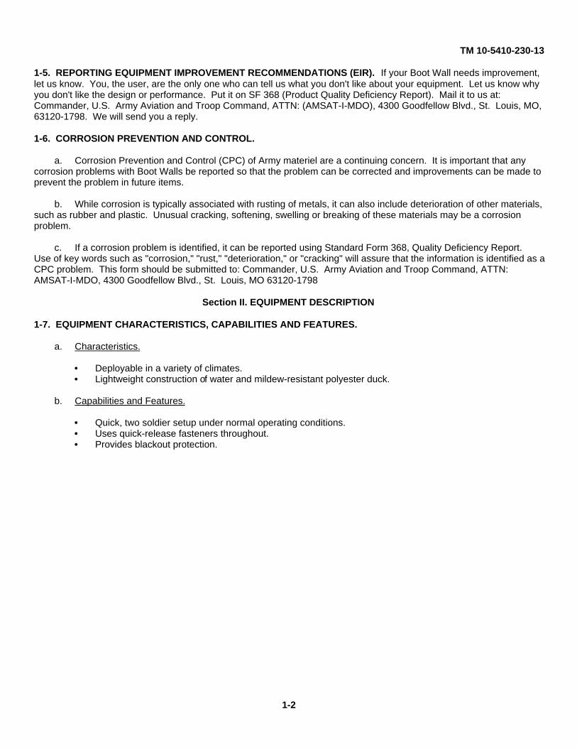
c. Type IV. The S-250E Boot Wall (1) is constructed of mildew and flame resistant polyester duck and is 11 feetwide, 8 feet high, and 5 feet deep. It is interchangeable with any other wall assembly of the MCPS tent. Quick releasefasteners (2) and hook and pile fastener tapes (3) connect the Boot Wall end panel assembly (4) to the MCPS tent roofcap and adjacent walls. The end panel assembly is fitted with a roll-up fabric door (5). A blackout wall (6) provides lightdiscipline and an electric panel access (7). An adjustable belly band assembly (8) and web straps (9) with hooks securesboot assembly to the shelter and HMMWV hood. Two SICPS tent poles (10) support the S-250E Boot Wall fabric.
1-5

TM 10-5410-230-13
1-9. EQUIPMENT DATA.
TYPE I TYPE II TYPE IVWEIGHT: 45 lbs(21 kg) 45 lbs(21 kg) 45 lbs(21 kg)DIMENSIONS:
Length 5 ft(1.52m) 5 ft(1.52m) 5 ft(1.52m)Width 8 ft(2.44m) 8 ft(2.44m) 8 ft(2.44m)Height 11 ft(3.36) 11 ft(3.36m) 11 ft(3.36m)
ENVIRONMENTAL:Setup -20°-110'F -20'-110°F -20°-110°F
Operate -40°-120°F -40°-120°F -40'-120'F
Section III. PRINCIPLES OF OPERATION
1-10. GENERAL. The Boot Walls are installed between the MCPS tent and another shelter or vehicle. Once installed,the Boot Wall provides a weather barrier allowing transit between MCPS tent and vehicle or shelter. The Boot Walls aredesigned to be interchangeable with a standard MCPS tent wall section. To install the Boot Wall, an existing tent wall isremoved and replaced by the Boot Wall. The vehicle or shelter is then fastened to the Boot Wall to complete thepassageway.
The M577 Boot Wall (type I) is used between the MCPS tent and the M577 tracked command post vehicle.
The RWS Boot Wall (type II) is used between the MCPS tent and M1037/M1042 HMMWV equipped with a Rigid WallShelter.
The S-250E Boot Wall (type IV) is used between MCPS tent and M1037/M1042 HMMWV equipped with the S-250Eelectrical equipment shelter.
1-6

TM 10-5410-230-13
CHAPTER 2
OPERATING INSTRUCTIONS
Subject PageSection I DESCRIPTION AND USE OF OPERATOR'S CONTROLS AND INDICATORS ................................ ........ 2-1
Section II OPERATOR PREVENTIVE MAINTENANCE CHECKS AND SERVICES(PMCS)................................ ................................ ................................ ................................ ............................... 2-12-1. GENERAL ................................ ................................ ................................ ................................ .................. 2-1
Section III OPERATION UNDER USUAL CONDITIONS................................ ................................ .......................... 2-92-2 SITE SELECTION................................ ................................ ................................ ................................ .............. 2-92-3 REMOVAL OF MCPS TENT WALL ................................ ................................ ................................ ................... 2-92-4 INSTALLING M577 BOOT WALL TYPE I ................................ ................................ ................................ .......... 2-102-5 INSTALLING THE RIGID WALL SHELTER BOOT WALL TYPE II ................................ ................................ ..... 2-142-6 INSTALLING THE S-250E BOOT WALL TYPE IV ................................ ................................ ............................. 2-192-7 REMOVING THE M577 BOOT WALL TYPE I ................................ ................................ ................................ .... 2-242-8 REMOVING THE RIGID WALL SHELTER BOOT WALL TYPE II ................................ ................................ ...... 2-262-9 REMOVING THE S-250E BOOT WALL TYPE IV ................................ ................................ .............................. 2-292-10 PREPARATION FOR MOVEMENT................................ ................................ ................................ .................. 2-31
Section IV OPERATION UNDER UNUSUAL CONDITIONS................................ ................................ ..................... 2-312-11 GENERAL................................ ................................ ................................ ................................ ........................ 2-31
Section I. DESCRIPTION AND USE OF OPERATOR'S CONTROLS AND INDICATORS
Not applicable.
Section II. OPERATOR PREVENTIVE MAINTENANCE CHECKS AND SERVICES (PMCS)
2-1. GENERAL. Table 2-1, Preventive Maintenance Checks and Procedures for SICPS Boot Walls, has been providedso you can keep your equipment in good operating condition and ready for its primary mission.
a. Warnings and Cautions. Always observe Warnings and Cautions appearing in your PMCS table. Warningsand Cautions appear before applicable procedures. You must observe these Warnings and Cautions to prevent seriousinjury to yourself and others or prevent your equipment from being damaged.
b. Explanation of Table Entries.
(1) Item Number Column. Numbers in this column are for reference. When completing DA Form 2404(Equipment Inspection and Maintenance Worksheet), include the item number for the check/service indicating a fault.Item numbers also appear in the order in which you must do the checks and services listed.
(2) Interval Column. This column tells you when you must do the procedure in the procedure column. TheBEFORE procedures must be done before you operate or use the equipment for its intended mission. DURINGprocedures must be done during the time you are operating or using the equipment for its intended mission. AFTERprocedures must be done immediately after you have operated or used the equipment.
(3) Location, Check/Service Column. This column provides the location and the item to be checked orserviced. The item location is underlined.
2-1

TM 10-5410-230-13
(4) Procedure Column. This column gives the procedure you must do to check or service the item listed inthe Check/Service column to know if the equipment is ready or available for its intended mission or for operation. Youmust do the procedure at the time specified in the interval column.
(5) Not Fully Mission Capable If: Column. Information in this column tells you what faults will keep yourequipment from being capable of performing its primary mission. If you make check and service procedures that showfaults listed in this column, do not operate the equipment. Follow standard operating procedures for maintaining theequipment or reporting equipment failure.
c. Other Table Entries. Be sure to observe all special information and notes that appear in your table.
2-2

TM 10-5410-230-13
Table 2-1. OPERATOR PREVENTIVE MAINTENANCE CHECKS AND SERVICES
ItemNo.
IntervalLocationItem to
check/serviceProcedure Not Fully Mission Capable If:
M577 Boot Wall,RWS Boot Wall,
S-250E Boot Wall
1 Before Boot Assembly,End PanelAssembly
Check for tears, punctures, andseparated seams on boot assembly(1) and end panel assembly (2)
Tears, punctures or separated seamsexist which allow weather to enter orlight to escape Boot Wall.
2 Before Hook and PileFasteners
Inspect all hook and pile fasteners (3)for cleanliness and secure hold.Remove dirt by brushing fastenerstrips. Inspect Fasteners for loosestitching to fabric.
Boot Wall can not be secured inplace because hook and pilefasteners do not hold securely whenpressed together or are looselystitched to fabric.
3 Before Straps, QuickDisconnectFasteners
Check Straps (4) and quickdisconnect fasteners (5) for fraying,tears, broken hardware and loosestitching to fabric.
Boot Wall can not be secured inplace because straps and quickdisconnect fasteners are frayed, torn,broken or loosely stitched to fabric.
2-3

TM 10-5410-230-13
Table 2-1. OPERATOR PREVENTIVE MAINTENANCE CHECKS AND SERVICES (CONT).
ItemNo.
IntervalLocationItem to
check/serviceProcedure Not Fully Mission Capable If:
4 Before Frame (RWSBoot Wall) andTent Pole (S-
250E Boot Wall)
Inspect frame (1) or pole (2) forbroken or missing hardware. Inspectpole for ability to lock securely whencompressed.
Frame or tent pole can not supportweight of Boot Wall. Tent pole canbe adjusted to proper height.
2-4

TM 10-5410-230-13
Table 2-1. OPERATOR PREVENTIVE MAINTENANCE CHECKS AND SERVICES (CONT).
ItemNo.
IntervalLocationItem to
check/serviceProcedure Not Fully Mission Capable If:
M577 Boot Wall,RWS Boot Wall,
S-250E Boot Wall
5 During Boot Assembly,End PanelAssembly
Check for tears, punctures, andseparated seams on boot assembly(1) and end panel assembly (2).
Tears, punctures or separated seamsexist which allow weather to enter orlight to escape Boot Wall.
6 During Hook and PileFasteners
Inspect all hook and pile fasteners (3)for cleanliness and secure hold.Remove dirt by brushing fastenerstrips. Inspect Fasteners for loosestitching to fabric.
Boot Wall can not be secured inplace because hook and pilefasteners do not hold securely whenpressed together or are looselystitched to fabric.
7 During Straps, QuickDisconnectFasteners
Check Straps (4) and quickdisconnect fasteners (5) for fraying,tears, broken hardware and loosestitching to fabric.
Boot Wall can not be secured inplace because straps and quickdisconnect fasteners are frayed, torn,broken or loosely stitched to fabric.
2-5

TM 10-5410-230-13
Table 2-1. OPERATOR PREVENTIVE MAINTENANCE CHECKS AND SERVICES (CONT).
ItemNo.
IntervalLocationItem to
check/serviceProcedure Not Fully Mission Capable If:
8 During Frame (RWSBoot Wall) and
Tent Pole (S-250EBoot Wall)
Inspect frame (1) or pole (2) forbroken or missing hardware. Inspectpole for ability to lock securely whencompressed.
Frame or tent pole can not supportweight of Boot Wall. Tent pole canbe adjusted to proper height.
2-6

TM 10-5410-230-13
Table 2-1. OPERATOR PREVENTIVE MAINTENANCE CHECKS AND SERVICES (CONT).
ItemNo.
IntervalLocationItem to
check/serviceProcedure Not Fully Mission Capable If:
M577 Boot Wall,RWS Boot Wall,
S-250E Boot Wall
9 After Boot Assembly,End PanelAssembly
Check for tears, punctures, andseparated seams on boot assembly(1) and end panel assembly (2).
Tears, punctures or separated seamsexist which allow weather to enter orlight to escape Boot Wall.
10 After Hook and PileFasteners
Inspect all hook and pile fasteners (3)for cleanliness and secure hold.Remove dirt by brushing fastenerstrips. Inspect Fasteners for loosestitching to fabric.
Boot Wall can not be secured inplace because hook and pilefasteners do not hold securely whenpressed together or are looselystitched to fabric.
11 After Straps, QuickDisconnectFasteners
Check Straps (4) and quickdisconnect fasteners (5) for fraying,tears, broken hardware and loosestitching to fabric.
Boot Wall can not be secured inplace because straps and quickdisconnect fasteners are frayed, torn,broken or loosely stitched to fabric.
2-7

TM 10-5410-230-13
Table 2-1. OPERATOR PREVENTIVE MAINTENANCE CHECKS AND SERVICES (CONT).
ItemNo.
IntervalLocationItem to
check/serviceProcedure Not Fully Mission Capable If:
12 After Frame (RWSBoot Wall) and
Tent Pole (S-250EBoot Wall)
Inspect frame (1) or pole (2) forbroken or missing hardware. Inspectpole for ability to lock securely whencompressed.
Frame or tent pole can not supportweight of Boot Wall. Tent pole canbe adjusted to proper height.
2-8

TM 10-5410-230-13
Section III. OPERATION UNDER USUAL CONDITIONS
2-2. SITE SELECTION. Select an area large enough for vehicle and erected Boot Wall. Ensure that area is relativelylevel and is free of large holes, trees, rocks, and debris. Make sure that site will drain properly in event of inclementweather. Positioning front of vehicle lower than rear will encourage proper drainage. Check unit SOP to ensure that siteselection and MCPS tent layout will be acceptable.
2-3. REMOVAL OF MCPS TENT WALL. If a wall assembly is already in place on the side of the MCPS tent that will beattached to Boot Wall, it must be removed as follows:
a. Release all quick disconnect (1) and hook and pile fasteners (2) at inside and outside corners.
b. Remove wall (3) by releasing all quick disconnect (1) and hook and pile fasteners (2) from roof assembly.
c. Fold wall (3) with identification label visible and place in fabric transport bag.
2-9

TM 10-5410-230-13
2-4. INSTALLING M577 BOOT WALL TYPE I.
NOTE
If a wall assembly is in place where Boot Wall is to be installed, it mustbe removed prior to installation. See paragraph 2-3 for removalinstructions.
a. Unpack M577 Boot Wall type I and inspect in accordance with Table 2-1, Operator PMCS.'
b. Standing inside MCPS tent, line up Boot Wall end panel (1) and fasten it to MCPS tent roof cap (2) with quickrelease fasteners (3).
c. Starting at center of Boot Wall, line up pile fastener tape (4) on end panel assembly (1) with hook fastener tape(4) on MCPS tent roof cap assembly (2) and press them together. Work from center outward in order toprevent wrinkles in hook and pile fastener tapes.
2-10

TM 10-5410-230-13
d. From outside MCPS tent overlap Boot Wall end wall panel (1) and existing walls (2) and connectcorresponding quick release fasteners (3) and side hook and pile fastener tapes (4). Make sure leg assembliesstay inside MCPS tent.
e. Pull outside roof cap corner flaps (5) down and press the hook and pile fasteners (6).
f. Fasten the row of quick disconnect fasteners (7) on the inside corners of each wall. Draw the buckle straps (8)tight. Make sure leg assemblies stay inside MCPS tent.
2-11

TM 10-5410-230-13
2-4. INSTALLING M577 BOOT WALL TYPE I (CONT).
WARNING
Use a ground guide when backing a vehicle. Failure toobserve this warning may result in death or serious injury.
Make sure radio sets are turned off for the rest of theBoot Wall installation. Personal injury may result if radiosets are used during Boot Wall installation.
g. Center rear of M577 (1) on Boot Wall (2) and position it four to five feet away from t he MCPS tent.
h. Loosen bolts (3) that attach hold-down track (4) along top rear of the M577 (1).
i. If antenna (5) is present, place sleeve (6) over antenna cylinder. If your Boot Wall has no antenna sleeve,antenna (5) must be removed.
2-12

TM 10-5410-230-13
j. Push hem (7) along top forward edge of Boot Wall under track (4), making sure hem (7) is centered on M577, then tighten bolts (3) securing track (4).
k. From inside Boot Wall (2), loosen wing nuts (8) securing tracks (9) along right and left rear sides of M577 (1). Placehems (10) under tracks (9) and tighten wing nuts (8).
l. Attach straps (11) on top of Boot Wall (2) to corresponding loops (12) on top of the M577 (1) and tighten straps (11).
m. If antenna is present, tighten sleeve (6) around antenna cylinder (5) using draw string (13).
n. Attach right (1) and left (2) halves of blackout skirt to underside of M577 (3) by attaching straps (4) to loops (5) on underside of M577.
o. Connect right (1) and left (2) halves of the blackout skirt together with hook and pile fasteners tapes (6).
p. Fasten quick release fastener (7) on right fender skirt (8)
2-13

TM 10-5410-230-13
2-5. INSTALLING TEHE RIGID WALL SHELTER BOOT WALL TYPE II.
NOTE
If a wall assembly is in place where Boot Wall is to be installed, it must be removed priorto installation. See paragraph 2-3 for removal instructions.
a. Unpack the Rigid Wall Shelter (RWS) Boot Wall and inspect in accordance with Table 2-1, Operator PMCS.
b. Standing inside the MCPS tent, line up Boot Wall end panel (1) and fasten it to MCPS tent roof cap (2) with quickrelease fasteners (3). Ensure that roll-up door (4) is down (closed) and secured with hook and pile fastener tapes.
c. Starting in center of Boot Wall, line up pile fastener tape on end panel assembly (1) with hook fastener tape onMCPS tent roof cap assembly (2) and press them together. Work from center outward in order to prevent wrinklesin hook and pile fastener tapes.
2-14

TM 10-5410-230-13
d. From outside MCPS tent overlap Boot Wall end wall panel (1) with two adjacent walls (2), and connectcorresponding quick release fasteners (3) and side hook and pile fastener tapes (4). Make sure leg assemblies stayinside fabric.
e. Pull the outside roof cap corner flaps (5) down and press the hook and pile fasteners (6).
f. Fasten the row of quick disconnect fasteners (7) on inside corners of each wall. Draw buckle straps (8) tight. Makesure leg assemblies stay inside fabric.
g. Open roll-up door (9) and secure with straps (10).
2-15

TM 10-5410-230-13
2-5. INSTALLING THE RIGID WALL SHELTER BOOT WALL TYPE II (CONT).
NOTE
Swivel feet may already be installed on rear of RWS.
h. Attach swivel feet (1) to RWS (2) using captive screws (3) and two threaded inserts (4) already installed in rear ofRWS (2).
i. Assemble frame by attaching upright bars (5) to U-shaped header (6) and inserting locking pins (7).
j. Place frame header bar (6) into boot assembly (8) and fasten hook and pile fastener tapes (9) on three header flaps(10) around header bar (6).
2-16

TM 10-5410-230-13
WARNING
Use a ground guide when backing a vehicle. Failure to observe this warning mayresult in death or serious injury.
Make sure the radio sets are turned off for the rest of the Boot Wall installation.Personal injury may result if radio sets are used during Boot Wall installation.
k. Center HMMWV with RWS (1) on Boot Wall (2) and back it up to within four to five feet of MCPS tent (3).
l. Remove whip antennas (4) from their mounts (5) on rear of RWS (1). (Use folding steps on passenger side of RWSto access roof.)
m. Lift top of boot assembly (2) over antenna mounts (5) on RWS (1). Place the antenna sleeves (6) over the antennamounts (5).
n. Install whip antennas (4) into mounts (5). Tighten sleeves (6) using tie tapes (7).
o. Remove belly band webbing (8) from dee-ring buckle (9) and separate hook and pile fastener tapes (10) on driverside of boot assembly.
2-17

TM 10-5410-230-13
2-5. INSTALLING THE RIGID WALL SHELTER BOOT WALL TYPE II (CONT).
NOTE
Ensure frame stays in corner of fabric to ensure proper fit.
p. Lift boot assembly (1) up using frame (2). Place ends of upright bars (2) onto swivel feet (3) and fasten usinglocking pins (4).
q. Wrap remaining portion of boot assembly (1) completely around RWS (5).
r. Thread belly band webbing (7) through dee-ring buckle (8) and tighten.
s. Fasten upper and lower portions of the boot assembly (1) together with hook and pile fastener tapes (6) on driverside.
t. If high winds are expected, install rope loops (9) (Appendix E, Item 1) and tent stakes (10) (Appendix E, Item 2) onboth sides of boot assembly. Use whichever foot loop (11) is closest to ground level or provides best hold.
2-18

TM 10-5410-230-13
2-6. INSTALLING THE S-250E BOOT WALL TYPE IV.
NOTE
If a wall assembly is in place where Boot Wall is to be installed, it must be removed priorto installation. See paragraph 2-3 for removal instructions.
a. Unpack S-250E Boot Wall and inspect in accordance with Table 2-1, Operator PMCS.
b. Standing inside MCPS tent, line up Boot Wall end panel (1) and fasten it to roof cap (2) with quick release fasteners(3). Ensure that roll-up door (4) is down (closed) and secured with hook and pile fastener tapes.
c. Starting in center of end panel, line up the pile fastener tape on end panel assembly (1) with hook fastener tape onMCPS tent roof cap assembly (2) and press them together. Work from center outward in order to prevent wrinklesin hook and pile fastener tapes.
2-19
TM 10-5410-230-13
2-6. INSTALLING THE S-250E BOOT WALL TYPE IV (CONT).
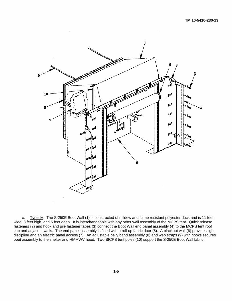
d. From outside MCPS tent, overlap end wall panel (1) with adjacent walls (2) and connect corresponding quickrelease fasteners (3) and side hook and pile fastener tapes (4). Make sure leg assemblies stay inside the MCPStent.
e. Pull outside roof cap corner flaps (5) down and press hook and pile fasteners (6).
f. Fasten row of quick disconnect fasteners (7) on inside corners of each wall. Draw the buckle straps (8) tight.
g. Open roll-up door (9) and secure with straps (10).
2-20

TM 10-5410-230-13
WARNING
Use a ground guide when backing a vehicle. Failure to observe this warning mayresult in death or serious injury.
Make sure the radio sets are turned off for the rest of the Boot Wall installation.Personal injury may result if radio sets are used during Boot Wall installation.
h. Center HMMWV with S-250E shelter (1) on Boot Wall (2) and back up to within four to five feet of MCPS tent (3).
i. Remove ladder from storage bracket on rear of S-250E and ensure HMMWV tailgate is up and secured.
j. Remove web belly band (4) from dee-ring buckle (5) and separate hook and pile fastener tapes (6) on driver's side ofBoot Wall (2) and blackout wall inside.
k. Pull Boot Wall (2) over top of S-250E shelter (1). Boot wall should overlap S-250E approximately 15-18 inches.The blackout wall should fit flush against rear of S-250E and the ladder bracket should be placed into the pocket inblackout wall. If necessary, readjust HMMVW to attain proper fit.
l. Attach web strap hooks (7) to lifting eyes (8) located on hood of HMMWV and tighten webs straps so that blackoutwall is snug against rear of S-250E shelter.
2-21

TM 10-5410-230-13
2-6. INSTALLING THE S-250E BOOT WALL TYPE IV (CONT).
m. Wrap remainder of boot assembly (2) around S-250E shelter and thread web belly band (4) through dee-ring buckle(5) and tighten.
n. Fasten upper and lower portions of boot assembly (2) together with hook and pile fastener tapes (6) on driver's side.
o. Insert telescopic poles (1) into second and third loops (2) and bottom grommet (3).
p. Extend poles (1) by raising upper portion thru upper loop (4) and inner grommet (5) at top of Boot Wall until BootWall is taut.
q. Secure guy lines (6) (Appendix C, Section III, Item 1) from outer grommet (7) on each side of Boot Wall by stakinginto ground with tent stakes (8) (Appendix C, Section III, Item 2), or connecting to existing MCPS tent stakes.Adjust slips (9) (Appendix C, Section III, Item 3) to secure.
2-22

TM 10-5410-230-13
r. Lower HMMWV tailgate (1) and pass tailgate chains (2) thru sleeves (3) and connect to HMMWV. Secure sleeves(3) with tie-tapes.
s. From inside Boot Wall, connect fastener tapes (4) on upper and lower portions of blackout wall (5).
t. Pull shock cords (6) between S-250E and bumper and secure to frame of HMMVW.
u. Fasten buckle (7) and tuck flap between cradle and S-250E.
2-23

TM 10-5410-230-13
2-7. REMOVING THIE M577 BOOT WALL TYPE L
a. Separate hook and pile fasteners (1) joining right (2) and left (3) halves of blackout skirt together.
b. Release straps (4) from underside of M577 (5) to free right (2) and left (3) halves of the blackout skirt.
c. Disconnect quick release fastener (6) on right fender assembly.
2-24

TM 10-5410-230-13
d. Loosen wing nuts (1) securing hold down track (2) along sides of the M577 (3). Remove hem (4) from hold downtrack (2) and tighten wing nuts (1).
e. Unfasten straps (5) securing upper hem (6) of Boot Wall to loops (7).
f. Loosen bolts (1) securing hold down track (2) to top of the M577 (3). Remove hem (4) of Boot Wall (5) and tightenbolts (1).
g. If antenna (6) is present, remove antenna (6) from sleeve (7).
h. Remove Boot Wall (5) by releasing all quick disconnect (8) and hook and pile fasteners (9). Start from lower sidesand work upwards and then in towards center.
i. Fold Boot Wall with the identification label visible and stow.
NOTE
If MCPS tent is to remain in service, install wall unit in accordance with TM 10-5410-229-13&P.
2-25

TM 10-5410-230-13
2-8. REMOVING THE RIGID WALL SHELTER BOOT WALL TYPE II.
a. Open roll-up door (1) and secure with straps (2).
b. Untie antenna sleeve tie tapes (3) and disconnect whip antennaes (4) from their mounts (5) on Rigid Wall Shelter(RWS) (6).
c. If used, remove stakes (7) and loops (8) from foot loops (9) on both sides of Boot Wall.
d. Unthread belly band webbing (10) by lifting dee ring tab (11).
e. Separate hook and pile fastener tapes (12) on driver's side of boot assembly (13).
f. Holding frame (14) securely, remove locking pins (15) from swivel feet (16) and lower frame (14).
g. Lift boot assembly (13) up and over antenna mounts (5) and remove from RWS (6).
2-26
TM 10-5410-230-13
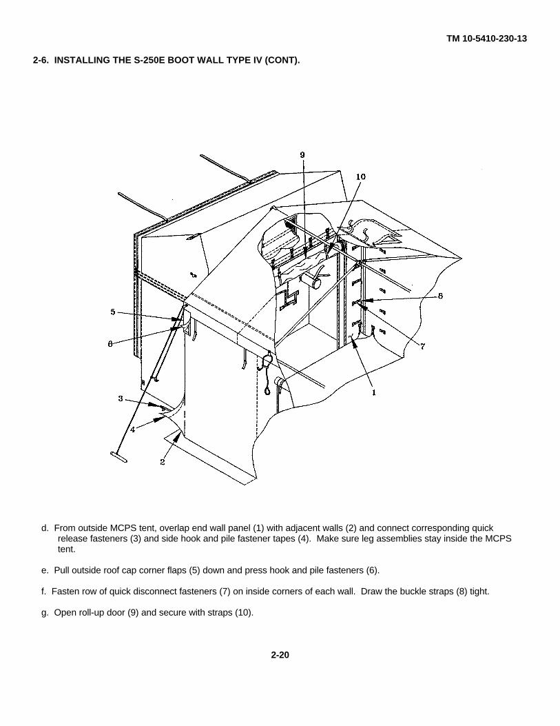
g. Remove frame (1) from boot assembly (2) by opening header flaps (3).
h. Disassemble frame by removing locking pins (4) and separating upright bars (5) from header bar (1).
NOTE
Swivel feet may be left on RWS for future use, but should be removed and packagedwith boot wall when boot wall is to be permanently separated from RWS.
i. Remove two swivel feet (6) from RWS by loosening captive screw (7). Stow swivel feet (6) with upright bars (5).
2-27

TM 10-5410-230-13
2-8. REMOVING TIE RIGID WALL SHELTER BOOT WALL TYPE II (CONT).
j. Close roll-up door (1) and secure hook and pile fastener tapes.
k. Remove Boot Wall (2) from MCPS tent (3) by releasing all quick release (4) and hook and pile fasteners (5). Starton lower sides and work upwards and then in toward center.
l. Fold the Boot Wall (2) with the identification label on door (1) visible and stow.
m. Install antennaes (6) on mounts (7) on RWS.
NOTE
If MCPS tent is to remain in service, Install wall unit in accordance with TM 10-5410-229-13&P.
2-28

TM 10-5410-230-13
2-9. REMOVING THE S-250E BOOT WALL TYPE IV.
a. Release guy lines (1) on each side of Boot Wall and pull out tent stakes (2) if possible.
b. Collapse telescopic poles (3) by raising upper portion of pole (3) slightly, holding locks (4), then lower polecompletely.
c. Remove each pole (3) from three loops (5) on side of Boot Wall.
d. Separate hook and pile fastener tapes (6) on upper and lower portions of blackout wall (7).
e. Release buckle (8) and remove bottom panel assembly (9) from cradle (10). Release shock cords (11) fromHMMVW frame.
f. Untie tie tapes, raise tailgate (12), and remove remove tailgate chains (13) from sleeves (14). Close and securetailgate.
2-29
TM 10-5410-230-13
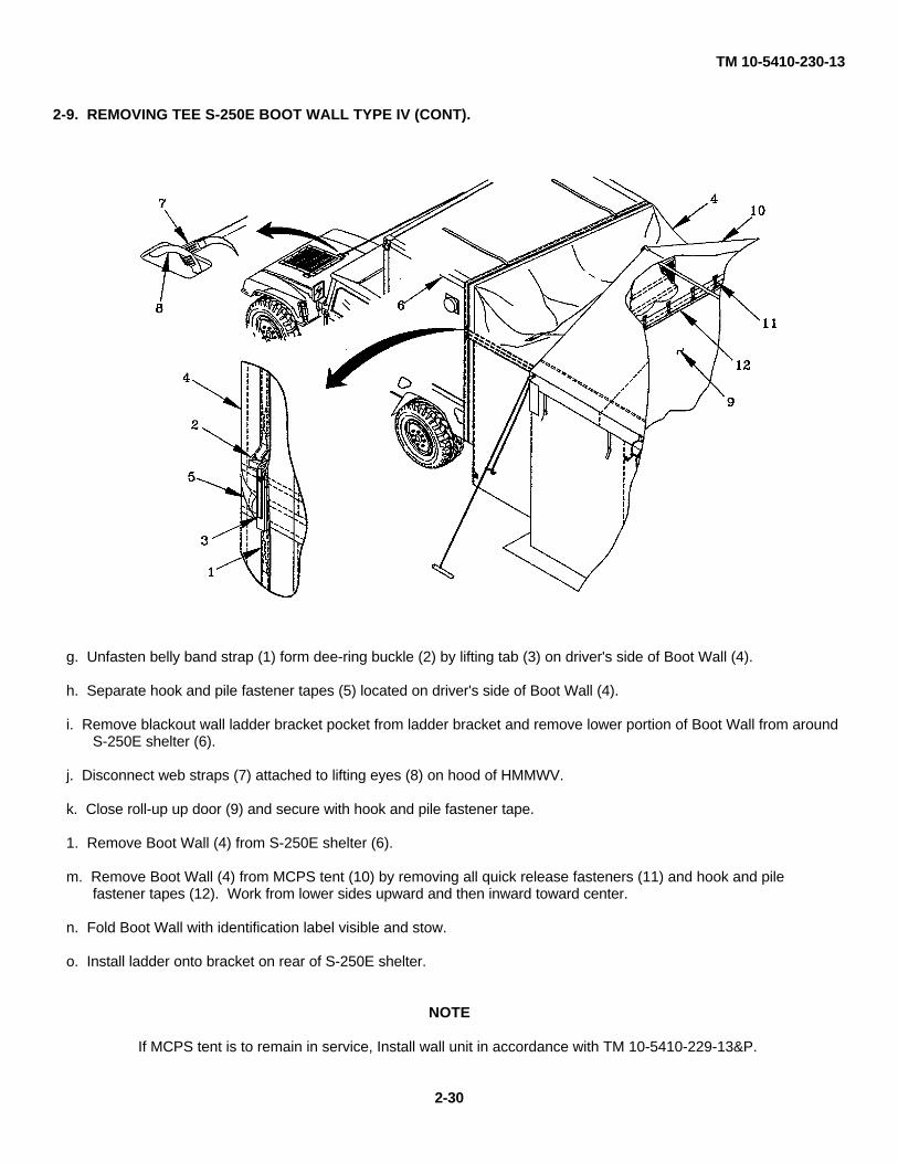
2-9. REMOVING TEE S-250E BOOT WALL TYPE IV (CONT).
g. Unfasten belly band strap (1) form dee-ring buckle (2) by lifting tab (3) on driver's side of Boot Wall (4).
h. Separate hook and pile fastener tapes (5) located on driver's side of Boot Wall (4).
i. Remove blackout wall ladder bracket pocket from ladder bracket and remove lower portion of Boot Wall from aroundS-250E shelter (6).
j. Disconnect web straps (7) attached to lifting eyes (8) on hood of HMMWV.
k. Close roll-up up door (9) and secure with hook and pile fastener tape.
1. Remove Boot Wall (4) from S-250E shelter (6).
m. Remove Boot Wall (4) from MCPS tent (10) by removing all quick release fasteners (11) and hook and pilefastener tapes (12). Work from lower sides upward and then inward toward center.
n. Fold Boot Wall with identification label visible and stow.
o. Install ladder onto bracket on rear of S-250E shelter.
NOTE
If MCPS tent is to remain in service, Install wall unit in accordance with TM 10-5410-229-13&P.
2-30

TM 10-5410-230-13
2-10. PREPARATION FOR MOVEMENT. Ensure that the Boot Wall is properly secured on or in vehicle prior to anymovements. If wet, avoid storing Boot Wall for a prolonged period to prevent mildew from occurring. Do not allow thefabric to come in contact with a hot exhaust pipe.
Section IV. OPERATION UNDER UNUSUAL CONDITIONS
2-11. GENERAL. Use the following information during unusual climatic conditions.
a. Operation in Wet Climate.
(1) Make sure no leaks occur over map boards or tables. Protect them if leaks occur.
(2) Make sure that all fasteners are connected and all hook and pile sections are mated.
(3) Dry the Boot Wall thoroughly before repacking.
b. Operation in Snow.
(1) Gently push up on the roof cap from inside the tent and Boot Wall to remove snow that may have piled up.
(2) Remove as much snow and ice as possible before taking the Boot Wall down.
2-31/(2-32 blank)


TM 10-5410-230-13CHAPTER 3
OPERATOR MAINTENANCE INSTRUCTIONS
Subject Page
Section I LUBRICATION INSTRUCTIONS ................................ ................................ ......................... 3-13-1 GENERAL ................................ ................................ ................................ .......................... 3-1
Section II TROUBLESHOOTING PROCEDURES ................................ ................................ ................ 3-13-2 INTRODUCTION TO TROUBLESHOOTING TABLE ................................ .......................... 3-1
Section III OPERATOR MAINTENANCE PROCEDURES ................................ ................................ ..... 3-53-3 INSPECTION ................................. ................................ ................................ ..................... 3-53-4 CLEANING ................................ ................................ ................................ ......................... 3-53-5 SEAM SEALING ................................ ................................ ................................ ................. 3-5
Section I. LUBRICATION INSTRUCTIONS
3-1. GENERAL. No lubrication is required.
Section II. TROUBLESHOOTING PROCEDURES
3-2. INTRODUCTION TO TROUBLESHOOTING TABLE.
a. Table 3-1 contains procedures to isolate Boot Wall defects that you can correct. The symptom indexlists the common malfunctions which may be encountered during inspection and operation of the Boot Walls.Use this index as a quick access to the troubleshooting procedures in Table 3-1.
b. After finding the malfunction you are experie ncing in the table, perform the tests, inspections, andcorrective actions in the order in which they appear.
c. This table can not list all malfunctions that may occur, all tests or all inspections needed to find thefault, nor all corrective actions required to correct the fault. If your malfunction is not listed or not corrected bycorrective action, notify your supervisor.
MALFUNCTION INDEXTroubleshooting
Procedure(paragraph)
M577 BOOT WALL TYPE IBoot Wall will not stay taut ................................ ................................ ............ 1
RWS BOOT WALL TYPE IIBoot Wall will not stay taut . ................................ ................................ ........... 2
S-250E BOOT WALL TYPE IVBoot Wall will not stay taut ................................ ................................ ............ 3
3-1

TM 10-5410-230-13
Table 3-1. OPERATOR TROUBLESHOOTING
MALFUNCTIONTEST OR INSPECTION
CORRECTIVE ACTION
1. M577 BOOT WALL WILL NOT STAY TAUT.
Step 1. Boot Wall hem (1) not secured in hold down tracks.
• Insert boot wall hem (1) into hold down tracks and tighten hold down tracks.
Step 2. Vehicle improperly positioned.• Position vehicle so it is centered on the MCPS and is within four to five feet(1.22m to 1.52m) of MCPS
3-2

TM 10-5410-230-13
Table 3-1. OPERATOR TROUBLESHOOTING (CONT)
MALFUNCTIONTEST OR INSPECTION
CORRECTIVE ACTION
2. RWS BOOT WALL WILL NOT STAY TAUT.
Step 1. Belly band (1) not secure around shelter.• Tighten belly band (1).
Step 2. Check tent stakes (2) on Boot Wall foot loops (3).• Anchor foot loops (3) securely with tent stakes (2).
Step 3. Vehicle improperly positioned.• Position vehicle so it is centered on the MCPS and is within four to five feet(1.22m to 1.52m) of MCPS
3-3

TM 10-5410-230-13
Table 3-1. OPERATOR TROUBLESHOOTING (CONT)
MALFUNCTIONTEST OR INSPECTION
CORRECTIVE ACTION
3. S-250E BOOT WALL WILL NOT STAY TAUT.
Step 1. Telescopic (1) poles not fully extended.
• Extend poles (1) until taught.
Step 2. Belly band (2) not secure around shelter.
• Tighten belly (2) band assembly.
Step 3. Web hood straps (3) not installed or not tight.
• Install and tighten both web hood straps (3) to lifting eyes on HMMWV hood.
Step 4. Vehicle improperly positioned.
• Position vehicle so it is centered on the MCPS and is within four to five feet
(1.22m to 1.52m) of MCPS
3-4

TM 10-5410-230-13
Section III. OPERATOR MAINTENANCE PROCEDURES
3-3. INSPECTION. Refer to Table 2-1, Operator PMCS for inspection procedures.
3-4. CLEANING. Clean all fabric components with mild soapy water (Appendix E, Item 1) andbrush (Appendix E, Item 2). Let fabric components air dry.
3-5. SEAM SEALING.
This task covers: Repair
NOTE
This procedure applies to all Boot Wall types.
INITIAL SETUP
Materials/Parts:Brush, varnish (Appendix E, Item 3)Goggles, chemical splash (Appendix E, Item 7)K-Cote seam sealer (Appendix E, Item 4)Latex gloves (Appendix E, Item 5)Respirator, air filtering (Appendix E, Item 8)Wiping rags (Appendix E, Item 9)
Equipment Condition:Area to be sealed must be clean and dry (refer to paragraph 3-4). Boot Wall may be left in serviceor removed and laid flat. Refer to paragraphs 2-7, 2-8, or 2-9 for removal procedures.
WARNING
FLAMMABLE. Do not smoke or use seam sealernear open flame.
HARMFUL FUMES. Use seam sealer in wellventilated area only. Use personal protectiveequipment to prevent inhalation of fumes . Failure toobserve this warning may result in serious injury topersonnel from inhalation of seam sealer fumes.
a. Brush seam sealer onto seam or area to be sealed. Seam sealer may be applied to inside oroutside of fabric. Ensure to overlap onto serviceable fabric by 1/2 inch.
b. Allow seam sealer to become dry to touch.c. Apply a second coat if desired.
3-5/(3-6 blank)


TM 10-5410-230-13
CHAPTER 4
UNIT MAINTENANCE INSTRUCTIONS
Subject Page
Section I UNIT LUBRICATION PROCEDURES ..................................... ................................ ............. 4-1Section II SERVICE UPON RECEIPT ............................................ ................................ ...................... 4-1
4-1 SERVICE UPON RECEIPT OF MATERIAL ............................... ................................ ......... 4-1
Section III.MAINTENANCE INSTRUCTIONS ...................................... ................................ .................. 4-24-2 GENERAL ....................................................... ................................ ................................ .... 4-24-3 REPAIR OF PUNCTURES IN FABRIC ASSEMBLIES ................................ ........................ 4-34-4 REPAIR OF HOLES AND TEARS IN FABRIC ASSEMBLIES . ................................ ............ 4-44-5 HAND STITCHING REPAIR IN FABRIC ASSEMBLIES ................................ ...................... 4-64-6 GROMMET MAINTENANCE INSTRUCTIONS ............................. ................................ ...... 4-94-7 FRAME ASSEMBLY (TYPE II ONLY) .................................. ................................ ............... 4-11
Section I. UNIT LUBRICATION PROCEDURES
Not applicable.
Section II. SERVICE UPON RECEIPT
4-1. SERVICE UPON RECEIPT OF MATERIAL. The Unit Maintenance technician should inspect theequipment before it is used. The technician will make the following checks when the equipment is unpacked:
a. Inspect the equipment for damage incurred during shipment. I f the equipment has beendamaged in shipment, report the damage on SF 364, Report of Discrepancy.
b. Check the equipment against the packing list to see if the shipment is complete. Report alldiscrepancies in accordance with DA Pam 738-750.
c. Check to see whether the equipment has been modified.
d. Service damaged equipment, as necessary, using Unit Maintenance procedures in SectionIII of this chapter to restore equipment to operable condition.
4-1

TM 10-5410-230-13
Section III. MAINTENANCE INSTRUCTIONS4-2. GENERAL.
a. This section contains unit maintenance applicable to the SICPS Boot Walls as authorized by theMaintenance Allocation Chart (MAC), Appendix B, of this manual. Unit Maintenance personnel may alsoperform all functions allocated to Operator Maintenance Level. The following topics are included as applicable:inspect, service, and repair.
b. All maintenance procedures in this section can be performed by one person unless otherwiseindicated in the initial setup. Read all warnings, cautions, notes and instructions carefully before attempting theprocedures. Read and understand all warnings at the front of this manual.
c. Fabric Repair and Stitching. Unit Maintenance repairs to the tent fabric assemblies will be limited tothe capabilities of the tentage repair kit (Appendix B, Section III, Item 1). Repair punctures up to 1/8" (3.2mm)in diameter using procedures in paragraph 4-3. For rips and tears not exceeding 12 inches in length and holesnot larger than 4 inches in diameter, refer to paragraph 4-4. Refer to paragraph 4-5 for hand stitchinginstructions. Whenever possible, repairs to fabric requiring stitching should be accomplished by sewingmachine at Direct Support Maintenance level. Consult FM 10-16 for more guidance on repairing fabric.
MAINTENANCE PROCEDURES
4-3 REPAIR OF PUNCTURES IN FABRIC ASSEMBLIES ................................ ........ 4-34-4 REPAIR OF HOLES AND TEARS IN FABRIC ASSEMBLIES ............................. 4-44-5 HAND STITCHING REPAIR IN FABRIC ASSEMBLIES ................................ ...... 4-64-6 GROMMET MAINTENANCE INSTRUCTIONS ................................ ................... 4-94-7 FRAME ASSEMBLY ................................ ................................ ........................... 4-11
4-2

TM 10-5410-230-13
4-3. REPAIR OF PUNCTURES IN FABRIC ASSEMBLIES.
This task covers: Repair of punctures 1/8 in. (3.2 mm) diameter or less
NOTE
This procedure applies to all Boot Wall types.
INITIAL SETUP
Tools:Tool Kit, Canvas Workers (Appendix B, Section III, Item 3)
Materials/Parts:Cloth, coatedScrub brush (Appendix E, Item 2)Soap, toilet, hand, cake (Appendix E, Item 1)
Equipment Conditions:Although the fabric assemblies can be repaired during operational use of the Boot Wall when necessary, it isrecommended that the fabric be repaired when the Boot Wall is not in use (refer to Chapter 2 for removalinstructions). The fabric assemblies should be clean and dry.
WARNING
The adhesive has a high alcohol content and is highly flammable. Use only inwell ventilated areas away from open flame. Do not smoke. In case of dizziness,leave area immediately and allow to ventilate. Failure to observe this warningmay result in severe injury or death.
b. Clean fabric (1) around hole (2) with mildsoapy water and brush, and allow to air dry
c. Using tongue depressor (3), dab adhesive (4)onto hole (2).
c. Work adhesive (4) into fabric (1) and hole (2)immediately and bridge hole (2) withadhesive (4) to seal it.
d. Allow adhesive (4) to dry.
4-3

TM 10-5410-230-13
4-4. REPAIR OF HOLES AND TEARS IN FABRIC ASSEMBLIES.
This task covers: Repair of holes and tears up to 4 in. (10.16 cm) in diameter
NOTE
This procedure applies to all Boot Wall types.
INITIAL SETUP
Tools:Tentage Repair Kit (Appendix B, Section III, Item 1)
Materials/Parts:Tentage Repair Kit (Appendix B, Section III, Item 1)Fabric
Equipment Conditions:Although the fabric assemblies can be repaired during operational use of the Boot Wall when necessary, it isrecommended that the fabric be repaired when the Boot Wall is not in use (refer to Chapter 2 for removalinstructions). The fabric assemblies should be clean and dry.
a. Obtain a clean, round patch (1) from bulkmaterial or salvage that is at least 1 in.larger than the damaged fabric area (2) in alldirections.
b. Place the damaged fabric area (2) on a flatsurface, or place a piece of softwood (orsimilar) under the damaged fabric area (2).
c. Center patch (1) over damaged fabric area(2). Draw a circle on fabric (2) around patch(1), then remove patch (1).
d. Clean damaged fabric area (2) inside circle.
WARNING
The adhesive has a high alcohol content and is highly flammable. Use only inwell ventilated areas away from open flame. Do not smoke. In case of dizziness,leave area immediately and allow to ventilate. Failure to observe this warningmay result in severe injury or death.
e. Place patch (1) face-down over circle (2).Coat patch evenly with adhesive (3), allowingadhesive (3) to overlap onto fabric (4) to forman adhesive circle. Remove patch (1) and setaside with adhesive side up.
f. Coat damaged fabric (4) with adhesive (3)inside circle (2). Allow adhesive (3) on patch(1) and adhesive circle (2) to dry.
4-4
TM 10-5410-230-13
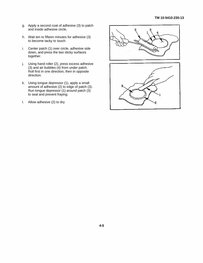
g. Apply a second coat of adhesive (3) to patchand inside adhesive circle.
h. Wait ten to fifteen minutes for adhesive (3)to become tacky to touch.
i. Center patch (1) over circle, adhesive sidedown, and press the two sticky surfacestogether.
j. Using hand roller (2), press excess adhesive(3) and air bubbles (4) from under patch.Roll first in one direction, then in oppositedirection.
k. Using tongue depressor (1), apply a smallamount of adhesive (2) to edge of patch (3).Run tongue depressor (1) around patch (3)to seal and prevent fraying.
l. Allow adhesive (2) to dry.
4-5

TM 10-5410-230-13
4-5. HAND STITCHING REPAIR IN FABRIC ASSEMBLIES.
This task covers: Repair
NOTE
This procedure applies to all Boot Wall types. Wheneverpossible, machine stitching is preferred over hand stitching.
INITIAL SETUP
Tools:Tentage Repair Kit (Appendix B, Section III, Item 1)
Materials/Parts:Tentage Repair Kit (Appendix B, Section III, Item 1)Thread
Equipment Conditions:Although the fabric assemblies can be repaired during operational use of the Boot Wall whennecessary, it is recommended that the fabric be repaired when the Boot Wall is not in use (refer toChapter 2 for removal instructions). The fabric assemblies should be clean and dry.
a. Preparing Needle and Thread.
NOTEIf you use two-strand thread you will need twice as much; if youuse four-strand, you will need four times as much.
(1) Estimate amount of thread required tocomplete stitching and cut thread tolength.
(2) Wax thread (1) by pressing between it-thumb and beeswax (2) and drawingentire length over beeswax (2).
4-6

TM 10-5410-230-13
(3) Thread sailmaker's needle (1) with waxedthread to form a single, two-, or four-strand thread as follows:(a) Single. Form a small loop near one
end and push the loop through theeye of the needle.
(b) Two-Strand. To make a doublestrand thread, pull the threadthrough the needle until the needle isat the midpoint of the single threadstrand.
(c) Four-strand. To form four-strandthread, bend a length of thread inhalf and insert the loop end into theeye of the needle, pulling it throughso that the eye is at the midpoint ofthe double strand of thread.
(4) Twist the strands together and rewax theentire length of thread.
(5) Tie knot at far end of the single, two-, orfour-strand thread.
4-7

TM 10-5410-230-13
4-5. HAND STITCHING REPAIR IN FABRIC ASSEMBLIES (CONT).
b. Handstitches. There are five common hand stitches used to mend fabric in different situations. Choosethe one that most closely resembles the repair you are making.
(1) Flat Stitch. This stitch is used as atemporary fastening until machinerepairs can be made. Pass the needleover and under an equal amount ofmaterial, each successive entering thematerial from the opposite side.
(2) Round Stitch. This stitch is used tohand-work grommets. Insert thematerials at right angles to the edge ofmaterial and bring cord around edgebefore making the next stitch.
(3) Overcast Stitch. This stitch is used toapply a hand-sewn patch. Insert theneedle through the material at an angleso that it comes out to one side andahead of the point of insertion, and bringthe cord over to the original line ofinsertion before making the next stitc h.
(4) Backstitch. This stitch is used to securean open seam. It is so named becausethe needle is always set back one half ofa stitch length into the last stitch made.Make two small stitches in the sameplace to secure the cord ends. Continueby inserting the needle into the middle ofthe preceding stitch and bringing it outon the same side of the material onestitch length in advance of the precedingstitch.
(5) Fishbone Stitch. This stitch is used tojoin edges of a tear unt il a patch can beapplied. Insert needle between two edgesof material to be sewn together. Take adiagonal stitch from one side toward theother, bringing the needle out betweenthe two edges. Repeat this operation onthe opposite side, and continuealternating stitches from side to side. Tokeep the stitches uniform, hold the edgessmoothly together. Make stitches firmly,but do not pull them tight enough topucker the fabric.
4-8

TM 10-5410-230-13
4-6. GROMMET MAINTENANCE INSTRUCTIONS.
This task covers: Repair
INITIAL SETUP
Tools:Lumber, softwood (Appendix E, Section II, Item 3)Tool kit, general mechanic's (Appendix B, Section III, Item 2)Repair kit, tentage (Appendix B, Section III, Item 1)
Materials/Parts:Grommet
Equipment Condition:Boot Wall removed (refer to paragraph 2-7, 2-8, or 2-9).
a If still attached, cut damaged grommet fromfabric.
NOTE
• If fabric repair is required, refer to paragraphs 4-4and 4-5 for repair and stitching instructions.
• A die-inserted grommet consists of two brass parts.The male half, called a barrel, is smooth. The femalehalf, called a washer, has spurs that grip the fabric.
b. Insert a grommet.
(1) Position fabric (1) face up on end grainsurface of softwood lumber.
(2) Using a size 5 cutting punch for a size 4grommet (or a size 6 cutting punch for- asize 5 grommet) and a rawhide mallet,cut a grommet hole in patch by hittingtop of cutting punch (2) with rawhidemallet.
4-9

TM 10-5410-230-13
4-6. GROMMET MAINTENANCE INSTRUCTIONS (CONT).
b. Insert a grommet. (Cont)
(3) Insert grommet barrel (1) into hole offabric (2) from the underside.
(4) Place fabric (2) and bottom (flat) part ofgrommet barrel (1) on grommet die (3).
(5) Place the grommet washer (4), spursdown, over grommet barrel (1).
(6) Insert cutting punch (5) into grommetbarrel (1) and hold in place.
(7) Hit top of cutting punch (5) with rawhidemallet (6) hard enough to clinch the partsto fabric without damaging grommet orfabric (2).
NOTE
When parts are clinched properly, the edge of thegrommet barrel has a smooth roll.
4-10

TM 10-5410-230-13
4-7. FRAME ASSEMBLY (TYPE II ONLY).
This task covers: Repair
INITIAL SETUP
Tools:Tool Kit, General Mechanics (Appendix B, Section III, Item 2)
Materials/Parts:Header barUpright bar
Equipment Condition:Frame removed from Boot Wall (refer to paragraph 2-8).
REPAIR
a.Remove Header and/or Upright Bar.
(1) Disconnect locking pins (1) that secureupright bars (2) to swivel feet (3)attached to HMMWV.
(2) Disconnect locking pins (4) that secureupright bars (2) to header bar (5).
(3) Remove upright bars (2) from header bar(5).
(4) Remove damaged upright bar (2) and/orheader bar (5).
b.Install Header and/or Upright Bar.
(1) Position header bar (5) and/or upright bar(2) inside Boot Wall.
(2) Connect upright bars (2) to header bar (5)and secure with locking pins (4).
(3) Insert locking pins (1) to secure uprightbars (2) to swivel feet (3) attached toHMMWV.
REPLACE
Replace unserviceable frame assembly with a serviceable on e from stock.
4-11(4-12 blank)


TM 10-5410-230-13CHAPTER 5
DIRECT SUPPORT MAINTENANCE INSTRUCTIONS
Subject Page
Section I REPAIR PARTS, SPECIAL TOOLS; TEST MEASUREMENT DIAGNOSTICEQUIPMENT (TMDE) AND SUPPORT EQUIPMENT ................................ .............................. 5-15-1 COMMON TOOLS AND EQUIPMENT ................................ ................................ .............. 5-15-2 SPECIAL TOOLS, TMDE, AND SUPPORT EQUIPMENT ................................ ................. 5-15-3 REPAIR PARTS ................................ ................................ ................................ ................. 5-1
Section II. MAINTENANCE PROCEDURES ................................ ................................ .......................... 5-15-4 GENERAL ................................ ................................ ................................ ......................... 5-15-5 MACHINE STITCHING ................................ ................................ ................................ ...... 5-15-6 AUTOMATIC STITCHING ................................ ................................ ................................ . 5-25-7 BOOT WALL ASSEMBLIES ................................ ................................ ............................. 5-35-8 FRAME ASSEMBLY (TYPE II ONLY) ................................. ................................ .............. 5-5
Section I. REPAIR PARTS, SPECIAL TOOLS; TEST MEASUREMENT DIAGNOSTIC EQUIPMENT(TMDE) AND SUPPORT EQUIPMENT
5-1. COMMON TOOLS AND EQUIPMENT. For authorized common tools and equipment, refer to the ModifiedTable of Organization and Equipment (MTOE), CTA 50-970, or CTA 8-100, as applicable to your unit.
5-2. SPECIAL TOOLS, TMDE, AND SUPPORT EQUIPMENT. No special tools or equipment are required toperform direct support maintenance on the SICPS Boot Walls.
5-3. REPAIR PARTS. Repair parts are listed and illustrated in the repair parts and special tools list TM 10-5410-230-13P covering unit maintenance for this equipment. Section II. MAINTENANCE PROCEDURES
5-4. GENERAL. This section contains Direct Support maintenance functions applicable to the SICPS BootWalls as authorized by the Maintenance Allocation Chart (MAC), Appendix B, Section II, of this manual. Thefollowing functions are included: repair. Procedures for machine stitching are provided in paragraph 5-5. DirectSupport maintenance personnel may also perform all functions allocated to the Unit and Operator levels.Additional guidance for repair of canvas and webbing is provided by FM 10-16.
5-5. MACHINE STITCHING. All stitch types, except bartacking, shall conform to FED-STD 751. Type 301 and401 stitching requires 5-7 stitches per inch. Bartacking shall be 1/8 inch in width and free of thread breaks andloose stitching. All stitching will be 1/8 inch from edge or spaced 1/8 inch apart, unless otherwise specified.
a. Thread Breaks. Thread breaks in stitching shall be overstitched not less than 1 inch at each break onstitch type 301, and not less than 1 1/2 inches at each break at stitch type 401. Thread breaks in type 401 maybe overstitched with stitch type 301. Thread breaks noted during inspection must be repaired by overstitchingthe existing stitching starting from a distance of 1 inch beyond the break. The ends of repair stitching are notrequired to be backstitched.
5-1

TM 10-5410-230-13
b. Stitching Ends. The ends of all type 301 and type 401 stitching shall be back stitched not less than oneinch unless turned under by a hem or held down by other stitching. Where 301 stitchings performedautomatically on stitch patters such as box, box with cross-stitch, "W' stitching or straight line tacking, at leastthree tying, overlapping, or back stitches shall be used to secure the ends of stitching. For size FF or F threaduse 6 to 8 stitches per inch, unless otherwise specified, stitch type shall be type 301 per FED-STD-751. Fuse allexposed ends of nylon webbing to prevent fraying. Avoid forming sharp edges.
c. Skipped Stitches. Two or more consecutively skipped stitches occurring in type 301 stitching shall beoverstitched not less than one inch. Any skipped stitches in type 401 stitching may be overmxitched with type301 stitching. Skipped stitches noted during inspection shall be repaired as specified for thread breaks in a.,above.
d. Stitching Tolerances. Unless otherwise specified, tolerances shall be as follows:
1/8 inch or more but less than 2 inches .............................. ±1/162 inches or more but less than 10 inches ..............................±1/810 inches or more but less than 30 inches ...........................±1/430 inches or more but less than 60 inches ............................±3/860 inches or more ................................ ................................ .±1/2
5-6. AUTOMATIC STITCHING. Automatic stitching machines may be used to perform any of the requiredstitch patterns. However, the requirements of the stitch pattern, stitches per inch, and size and type of threadmust be met. At least three or more overlapping, tying, or backstitches shall secure the ends of the stitching.
5-2

TM 10-5410-230-13
5-7. BOOT WALL ASSEMBLIES.
This task covers: Repair
NOTE
This procedure applies to all Boot Wall fabric components.INITIAL SETUP
Tools:Tentage Repair Kit (Appendix B, Section III, Item 1)Industrial Sewing Machine (Appendix B, Section III, Item 4)
Materials/Parts:Tentage Repair Kit (Appendix B, Section III, Item 1)
Equipment Condition:Boot Wall removed (refer to paragraph 2-7, 2-8, or 2-9). The fabric assemblies should be clean and dry.
REPAIR
a. Fabric. Refer to paragraphs 4-3 and 4-4 for fabric repair instructions. Any fabric component may be patched orsewn provided the repaired assembly provides a suitable degree of climatic protection and light discipline.
b. Fastener Tapes.NOTE
It is not necessary to replace an entire piece of fastener tape when only a small portion isdamaged. The damaged area can be cut out and replaced, leaving a portion of theoriginal piece in place.
(1) Carefully remove stitching (1), cut and remove damaged length of fastener tape (2). Ensure edges are cutstraight and no jagged edges remain.
(2) Measure width and length of damaged fastener tape (hook or pile) (2) to be replaced.
(3) Obtain a replacement part, or fabricate one from bulk or serviceable salvage stocks.
(4) Position fastener tape (2) and sew approximately 1/8 inch in from each edge. Ensure stitching (1) runs overfrom existing portion of fastener tape to the newly inserted portion (2).
5-3

TM 10-5410-230-13
5-7. BOOT WALL ASSEMBLIES. (CONT)
c. Webbing and Buckles.
NOTE
It is not necessary to replace an entire piece of webbing when only a small portion isdamaged and webbing does not need to be threaded through a buckle for adjustment.The damaged area can be cut out and replaced, leaving a portion of the original piece inplace.
(1) Identify the webbing (1) or buckle component (2) that is damaged and obtain a replacement, or fabricate onefrom bulk or serviceable salvage stocks. For fixed webbing pieces, add an inch to length of replacementpiece.
(2) Remove unserviceable webbing (1) or buckle (2) from assembly. Undamaged components should be removedand salvaged wherever possible.
(3) Assemble and sew buckles (2) and webbing (1) as required to form new assemblies.
(4) Position webbing (1) and buckle (2) assemblies on Boot Wall and sew. For fixed webbing pieces (3), overlapeach end by 1/2-inch.
5-4

TM 10-5410-230-13
5-8. FRAME ASSEMBLY (TYPE II ONLY).
This task covers: Repair
INITIAL SETUP
Tools:Tool Kit, Common No 1 (Appendix B, Section III, Item 4)Riveter, blind, hand (Appendix B, Section III, Item 5)
Materials/Parts:Pin and lanyard assemblySleeve swagingRivets (Appendix B, Section III, Item 5)
Equipment Condition:Frame assembly may be removed from service, but is not required to perform maintenance steps.
a. Replace Pin Assembly.
(1) Remove damaged pin (1) by separating ring end (2), inserting cable loop (3) under ring end (2) and twisting ring(2) until cable loop (3) is free.
(2) Obtain a new pin assembly (1) and install onto cable loop (3) by separating ring end (2), inserting cable loop (3)under ring end (2) and twisting ring (2) until loop (3) is captive inside ring.
b. Replace Pin and Lanyard Assembly.
(1) Drill out rivet (1) securing tab (2) to frame (3).
(2) Position new pin and lanyard assembly and rivet tab (2) to frame (3).
5-5/(5-6 blank)


TM 10-5410-230-13
APPENDIX A
REFERENCES
A-1. SCOPE. This appendix lists all forms, pamphlets, field manuals, technical manuals, army regulations, militaryspecifications, and military standards referenced in the manual.
A-2. DA PAMPHLETS.
The Army Maintenance Management System (TAMMS) ................................ ............................ DA PAM 738-750
A-3. FEDERAL STANDARDS.
Colors . FED-STD-595Stitches, Seams and Stitching ................................ ................................ ................................ ..........FED-STD-751
A-4. FIELD MANUALS.
Decontamination Procedures ................................ ................................ ................................ ..................... FM 3-5First Aid for Soldiers................................ ................................ ................................ ................................ FM 21-11General Repair of Tents, Canvas, and Webbing ................................ ................................ ..................... FM 10-16
A-5. FORMS.
Discrepancy in Shipment Report ................................ ................................ ................................ .................SF 361Equipment Inspection and Maintenance Worksheet ................................ ................................ ........ DA Form 2404Quality Deficiency Report ................................ ................................ ................................ ............................SF 368Recommended Changes to Equipment Technical Publications ................................ .................... DA Form 2028-2Report of Discrepancy ................................ ................................ ................................ ................................ .SF 364Report of Packaging and Handling Deficiencies ................................ ................................ ..........................SF 362
A-6. MILITARY STANDARDS.
Palletizing Unit Loads ............................................... ................................ ................................ ........MIL-STD-147Quality of Wood Members for Containers and Pallets ....................... ................................ ................ MILSTD-731Treatment and Painting of Material .................................... MILSTD-704
A-7. TECHNICAL MANUALS.
Camouflage Screen and Screen Support Systems ................................ ............................... TM 5-1080-200-13&PDestruction of Army Material to Prevent Enemy Use ................................ ................................ ........ TM 750-244-3Administrative Storage of Equipment ................................ ................................ ................................ TM 740-90-1Operators, Unit, and Direct Support Maintenance Manual including Repair Parts and SpecialTools List for Modular Command Post System (MCPS) ................................ ..................... TM 10-5410-229-13&PPreservation, Packaging, and Packing of Military Supplies and Equipment ................................ ........TM 38-230-2Unit and Direct Support Maintenance Repair Parts and Special Tools List for SICPSBoot Walls Type I, II, and IV................................ ................................ ................................ ..TM 10-5410-230-23P
A-8. MISCELLANEOUS
Army Medical Department Expendable/Durable Items................................ ................................ ........... CTA 8-100Expendable/Durable Items ................................ ................................ ................................ .................. CTA 50-970Metal Body Repair and Related Operations ................................ ................................ ............................. TC 9-510
A-1/(A-2 blank)


TM 10-5410-230-13
APPENDIX B
MAINTENANCE ALLOCATION CHART (MAC)
B-1 Change 1
Section I. INTRODUCTION
B-1. THE ARMY MAINTENANCE SYSTEM MAC This introduction provides a general explanation of all maintenance and repair functions authorized at the two maintenance levels under the Two-Level Maintenance System concept. This MAC (immediately following the introduction) designates overall authority and responsibility for the performance of maintenance functions on the identified end item or component. The application of the maintenance functions to the end item or component shall be consistent with the capacities and capabilities of the designated maintenance levels, which are shown on the MAC in column (4) as: Field - includes two columns, Unit maintenance and Direct Support maintenance. The Unit maintenance column is divided again into two more subcolumns, C for Operator or Crew and O for Unit maintenance.
Sustainment – includes two subcolumns, General Support (H) and Depot (D).
The tools and test equipment requirements (immediately following the MAC) list the tools and test equipment (both special tools and common tool sets) required for each maintenance function as referenced from the MAC. The remarks (immediately following the tools and test equipment requirements) contain supplemental instructions and explanatory notes for a particular maintenance function. B-2. MAINTENANCE FUNCTIONS Maintenance functions will be limited to and are defined as follows: 1. Inspect. To determine the serviceability of an item by comparing its physical, mechanical, and/or
electrical characteristics with established standards through examination (e.g., by sight, sound, or feel.) This includes scheduled inspection and gagings and evaluation of cannon tubes.
2. Test. To verify serviceability by measuring the mechanical, pneumatic, hydraulic, or electrical characteristics of an item and comparing those characteristics with prescribed standards on a scheduled basis, i.e., load testing of lift devices and hydrostatic testing of pressure hoses.
3. Service. Operations required periodically to keep an item in proper operating condition, e.g., to clean (includes decontaminate, when required), to preserve, to drain, to paint, or to replenish fuel, lubricants, chemical fluids, or gases. This includes scheduled exercising and purging of recoil mechanisms. The following are examples of service functions:
a. Unpack. To remove from packing box for service or when required for the performance of
maintenance operations. b. Repack. To return item to packing box after service and other maintenance operations. c. Clean. To rid the item of contamination.

TM 10-5410-230-13
Change 1 B-2
d. Touch up. To spot paint scratched or blistered surfaces.
e. Mark. To restore obliterated identification. 4. Adjust. To maintain or regulate, within prescribed limits, by bringing into proper position, or by setting
the operating characteristics to specified parameters.
5. Align. To adjust specified variable elements of an item to bring about optimum or desired performance
6. Calibrate. To determine and cause corrections to be made or to be adjusted on instruments of test, measuring, and diagnostic equipment used in precision measurement. Consists of comparisons of two instruments, one of which is a certified standard of known accuracy, to detect and adjust any discrepancy in the accuracy of the instrument being compared.
7. Remove/Install. To remove and install the same item when required to perform service or other maintenance functions. Install may be the act of emplacing, seating, or fixing into position a spare, repair part, or module (component or assembly) in a manner to allow the proper functioning of an equipment or system.
8. Paint. To prepare and spray color coats of paint so that the ammunition can be identified and protected. The color indicating primary use is applied, preferably, to the entire exterior surface as the background color of the item. Other markings are to be repainted as original so as to retain proper ammunition identification.
9. Replace. To remove an unserviceable item and install a serviceable counterpart in its place. “Replace” is authorized by the MAC and assigned maintenance level is shown as the third position code of the Source, Maintenance and Recoverability (SMR) code.
10. Repair. The application of maintenance services, including fault location/troubleshooting, removal/installation, disassembly/assembly procedures and maintenance actions to identify troubles and restore serviceability to an item by correcting specific damage, fault, malfunction, or failure in a part, subassembly, module (component or assembly), end item, or system.
NOTE
The following definitions are applicable to the “repair” maintenance function: Services. Inspect, test, service, adjust, align, calibrate, and/or replace. Fault location/troubleshooting. The process of investigating and detecting the cause of equipment malfunctioning; the act of isolating a fault within a system or Unit Under Test (UUT). Disassembly/assembly. The step-by-step breakdown (taking apart) of a spare/functional group coded item to the level of its least component, that is assigned an SMR code for the level of maintenance under consideration (i.e., identified as maintenance significant). Actions. Welding, grinding, riveting, straightening, facing, machining, and/or resurfacing.

TM 10-5410-230-13
B-3 Change 1
11. Overhaul. That maintenance effort (service/action) prescribed to restore an item to a completely
serviceable/operational condition as required by maintenance standards in appropriate technical publications. Overhaul is normally the highest degree of maintenance performed by the Army. Overhaul does not normally return an item to like new condition.
12. Rebuild. Consists of those services/actions necessary for the restoration of unserviceable equipment to a like new condition in accordance with original manufacturing standards. Rebuild is the highest degree of material maintenance applied to Army equipment. The rebuild operation includes the act of returning to zero those age measurements (i.e., hours/miles) considered in classifying Army equipment/components.
B-3. EXPLANATION OF COLUMNS IN THE MAC, SECTION II Column (1) Group Number. Column (1) lists Functional Group Code (FGC) numbers, the purpose of which is to identify maintenance significant components, assemblies, subassemblies, and modules with the Next Higher Assembly (NHA). Column (2) Component/Assembly. Column (2) contains the names of components, assemblies, subassemblies, and modules for which maintenance is authorized. Column (3) Maintenance Function. Column (3) lists the functions to be performed on the item listed in column (2). (For detailed explanation of these functions refer to “Maintenance Functions” outlined above). Column (4) Maintenance Level. Column (4) specifies each level of maintenance authorized to perform each function listed in column (3), by indicating work time required (expressed as manhours in whole hours or decimals) in the appropriate subcolumn. This work time figure represents the active time required to perform that maintenance function at the indicated level of maintenance. If the number or complexity of the tasks within the listed maintenance function varies at different maintenance levels, appropriate work time figures are to be shown for each level. The work time figure represents the average time required to restore an item (assembly, subassembly, component, module, end item, or system) to a serviceable condition under typical field operating conditions. This time includes preparation time (including any necessary disassembly/assembly time), troubleshooting/fault location time, and quality assurance time in addition to the time required to perform the specific tasks identified for the maintenance functions authorized in the MAC. The system designations for the various maintenance levels are as follows: Field:
Sustainment:
C Operator or Crew maintenance O Unit maintenance F Direct Support maintenance
L Specialized Repair Activity H General Support maintenance D Depot maintenance

TM 10-5410-230-13
Change 1 B-4
NOTE
The “L” maintenance level is not included in column (4) of the MAC. Functions to this level of maintenance are identified by work time figure in the “H” column of column (4), and an associated reference code is used in the REMARKS column (6). This code is keyed to the remarks and the SRA complete repair application is explained there.
Column (5) Tools and Equipment Reference Code. Column (5) specifies, by code, those common tool sets (not individual tools), common Test, Measurement and Diagnostic Equipment (TMDE), and special tools, special TMDE and special support equipment required to perform the designated function. Codes are keyed to the entries in the tools and test equipment table. Column (6) Remarks Code. When applicable, this column contains a letter code, in alphabetic order, which is keyed to the remarks table entries. B-4. EXPLANATION OF COLUMNS IN THE TOOLS AND TEST EQUIPMENT REQUIREMENTS, SECTION III Column (1) - Tool or Test Equipment Reference Code. The tool or test equipment reference code correlates with a code used in column (5) of the MAC. Column (2) - Maintenance Level. The lowest level of maintenance authorized to use the tool or test equipment. Column (3) - Nomenclature. Name or identification of tool or test equipment. Column (4) - National Stock Number (NSN). The NSN of the tool or test equipment. Column (5) - Tool Number. The manufacturer’s part number. B-5. EXPLANATION OF COLUMNS IN REMARKS, SECTION IV Column (1) - Remarks Code. The code recorded in column (6) of the MAC. Column (2) - Remarks. This column lists information pertinent to the maintenance function being performed as indicated in the MAC.

TM 10-5410-230-13
B-5 Change 1
Section II. MAINTENANCE ALLOCATION CHART
FOR SICPS BOOT WALLS TYPES I, II, & IV
(4)
MAINTENANCE LEVEL FIELD SUSTAINMENT
UNIT DIRECT SUPPORT
GENERAL SUPPORT
DEPOT
(1)
GROUP NUMBER
(2)
COMPONENT/ ASSEMBLY
(3)
MAINTENANCE FUNCTION
C O F H D
(5)
TOOLS AND EQUIPMENT REFERENCE
CODE
(6)
REMARKS CODE
00 SICPS BOOT WALLS
01 M577 BOOT WALL
Inspect Service Repair Replace
0.1 0.2 0.2
0.1 0.5 0.5
1.0
1,2,3,4
A
02 RWS BOOT WALL
Inspect Service Repair Replace
0.1 0.2 0.2
0.1 1.0 0.5
1.5
1,2,3,4,5
0201 BOOT WALL ASSEMBLY, TYPE II (RWS)
Inspect Repair Replace
0.1 0.2
0.1 1.0 0.5
1.0
1,2,3,4
A
0202 FRAME ASSEMBLY
Inspect Repair Replace
0.1 0.1 0.5 0.2
0.5
2,5
03 S-250E BOOT WALL
Inspect Service Repair Replace
0.1 0.2 0.2
0.1 0.5 0.5
1.0
1,2,3,4
0301 BOOT WALL ASSEMBLY TYPE IV (S-250E)
Inspect Repair Replace
0.1 0.2
0.1 1.0 0.5
1.0
1,2,3,4
A
0302 TENT POLE Inspect Replace
0.1 0.1 0.1

TM 10-5410-230-13
Change 1 B-6
Section III. TOOLS AND TEST EQUIPMENT
FOR SICPS BOOT WALLS TYPES I, II, & IV
(1) TOOL OR TEST
EQUIPMENT REFERENCE
CODE
(2) MAINTENANCE
LEVEL
(3) NOMENCLATURE
(4) NATIONAL
STOCK NUMBER
(5) TOOL
NUMBER
1 0 Repair Kit Tentage 8340-00-262-5767 2 0 Tool Kit, General Mechanic’s 5180-00-177-7033 3 0 Tool Kit, Canvas Workers 5180-00-754-0731 4 F Sewing Machine, Industrial 3530-00-8924631 5 F Riveter, Blind, Hand, W/ Rivets 5120-01-289-4310
Section IV. REMARKS FOR
SICPS BOOT WALLS TYPES I, II, & IV
(1) REMARKS
CODE
(2) REMARKS
A Unit Level Repair is limited to the capabilities of the Tentage Repair Kit.

TM 10-5410-230-13
APPENDIX C
COMPONENTS OF END ITEM AND BASIC ISSUE ITEMS
Section I. INTRODUCTION
C-1. SCOPE. This appendix lists components of end item (COEI) and basic issue items (BII) for SICPS Boot Walls.Use it to help inventory items required for safe and efficient operation.
C-2. GENERAL. The Components of End Item and Basic Issue Items Lists are divided into the following sections.
a. Section II. Components of End Item List. This listing is for informational purposes only, and is not authority torequisition replacements. These items are part of the end item. They are removed and separately packaged fortransportation or shipment only when necessary. As part of the end item, these items must be with the end itemwhenever it is issued or transferred between property accounts. Illustrations are furnished to assist you in identifying theitems.
b. Section III. Basic Issue Items List. These are the minimum essential items required to place the bootwalls inoperation and to perform emergency repairs. Although shipped separately packaged, BII must be with the bootwallsduring operation and whenever it is transferred between property accounts. The illustrations will assist you with hard-to-identify items. This manual is your authority to request/requisition replacement BII based on TOE/MTOE authorization ofthe end item.
C-3. EXPLANATION OF COLUMNS. The following provides an explanation of columns found in the tabular listings:
a. Column (1) - Illustration/Item Number. Indicates the number of the illustration in which the item is shown and thenumber of the item.
b. Column (2) - National Stock Number. Indicates the National stock number assigned to the item and is used forrequisitioning purposes.
c. Column (3) - Description. Indicates the federal item name and if required a minimum description to identify andlocate the item. The last line for each item indicates the Federal Supply Code for Manufacturer (FSCM) or Commercialand Government Entity Code (CAGEC) in parentheses, followed by the part number. If the item you need is not thesame for different models of the equipment, a Usable On Code (UOC) will appear on the right side of the descriptioncolumn on the same line as the part number. These codes are identified below:
UOC .................. MODELFJG ................... M577 BOOT WALL, TYPE I, GREENFJH ................... M577 BOOT WALL, TYPE I, TANFJJ ................... RWS BOOT WALL, TYPE II, GREENFJL ................... RWS BOOT WALL, TYPE II, TANFJL ................... S-250E BOOT WALL, TYPE IV, GREENFJM .................. S-250E BOOT WALL, TYPE IV, TAN
d. Column (4) - Unit of Measure (U/M). Indicates the measure used in performing the actualoperational/maintenance function. This measure is expressed by a two-character alphabetical abbreviation (e.g. ea, in,pr.)
e. Column (5) - Quantity required (Qtv rqr). Indicates the quantity of the item authorized to be used with/on theequipmentment.
C-1

TM 10-5410-230-13
Section II. COMPONENTS OF END ITEM LIST
(1) (2) (3) (4) (5)ILLUS/ITEM NATIONAL STOCK DESCRIPTION QTY
NO NUMBER (CAGEC)PART NUMBER UOC U/M REQD
1 M577 BOOT.WALL ASSEMBLY (TYPE I, EA 15410-01-378-8301 CLASS 1, GREEN (FJG)5410-01-380-2241 CLASS 2, TAN (FJH)
2 RWS BOOT ASSEMBLY (TYPE II) EA 15420-02-3644497 CLASS 1, GREEN (FJJ) UNASSIGNED CLASS 2, TAN (FJK)
(81337)54-8184-23 FRAME ASSEMBLY, RWS BOOTWALL EA 1
(81337)5-48202 (FJJ, FJK)
4 S-250E BOOT WALL ASSEMBLY EA 15420-02364-4497 CLASS 1, GREEN (FJL) UNASSIGNED CLASS 2, TAN (FJM)
(81337)5-4-8213-2
5 5410-01333-4128 TELESCOPIC POLE EA 2(81337)5-46980 (FJL,FJM)
C-2

TM 10-5410-230-13
Section III. COMPONENTS OF END ITEM LIST
(1) (2) (3) (4) (5)ILLUS/ITEM NATIONAL
STOCKDESCRIPTION QTY
NO NUMBER (CAGEC)PART NUMBER UOC U/M REQD
1 GUY LINE (FFJ, FJM) EA 2
2 8340-00-823-7451 TENT PIN, WOOD (FFJ, FJM) EA 2
3 SLIP, TENT GUY LINE (FFJ, FJM) EA 2
4 TECHNICAL MANUAL, EA 2OPERATOR'S, UNIT AND DIRECT SUPPORTMAINTENANCE MANUAL FOR SICPS BOOTWALLS TYPE I, 11, AND IV, TM 10-5410-230-13
5 REPAIR PARTS AND SPECIAL TOOLS LIST FOR EA 1SICPS BOOT WALLS TYPES I, 11, AND IV, TM 10-5410-230-23P
C-3/(C-4 blank)


TM 10-5410-230-13
APPENDIX D
ADDITIONAL AUTHORIZATION LIST
Section I. INTRODUCTION
D-1. SCOPE. This appendix lists additional items that you are authorized for the support of the Boot walls, Type I, TypeII, and Type IV.
D-2. GENERAL. This list identifies items that do not have to accompany the boot walls and that do not have to beturned in with it. These items are authorized to you by CTA, MTD, TDA, or JTA.
D-3. EXPLANATION OF LISTING. National stock number, descriptions, and quantities are provided to help you identifyand request the additional items you require to support this equipment. If the item required differs for different models ofthis equipment, see the "USED ON CODE" (UOC) column for the applicable model or models. Codes used are:
UOC.................... MODELFJG .................... M577 BOOT WALL, TYPE I, GREENFJH .................... M577 BOOT WALL, TYPE I, TANFJJ ..................... RWS BOOT WALL, TYPE II GREENFJK .................... RWS BOOT WALL, TYPE II TANFJL ..................... S-250E BOOT WALL, TYPE IV GREENFJM .................... S-250E BOOT WALL, TYPE IV TAN
Section II. ADDITIONAL AUTHORIZATION LIST
(1) (2) (3) (4) (5)Item National stock Description QtyNo. number (CAGEC)Part Number UOC U/M Auty1 ROPE (FJJ,FJK) FT 2
2 8340-00-823-7451 TENT PIN, WOOD (FJJ, FJK) EA 2
D-1/(D-2 blank)


TM 10-5410-230-13APPENDIX E
EXPENDABLE AND DURABLE ITEMS LIST
Section I. INTRODUCTION
E-1. SCOPE. This appendix lists expendable and durable items that you will need to operate and maintain the BootWalls. This listing is for information only and is not authority to requisition the listed items. These items are authorizedto you by CTA 50-970, Expendable/Durable Items (except Medical, Class V, Repair Parts, and Heraldic Items), or CTA 8-100, Army Medical Department Expendable/Durable Items.
E-2. EXPLANATION OF COLUMNS.
a. Column 1. Item Number. This number is assigned to the entry in the listing and is referenced in the narrativeinstructions to identify the item (e.g. "Use dry cleaning solvent, item 4, App. F").
b. Column 2. Level. This column identifies the lowest level of maintenance that requires the item.
C .................... Crew/OperatorO .................... Unit maintenanceF ..................... Direct support maintenance
c. Column 3. National Stock Number. This is the national stock number assigned to the item. Use it to requisitionthe item.
d. Column 4. Item Name, Description, Commercial and Government Entity Code (CAGEC), and Part Number . Thisprovides the other information you need to identify the item.
e. Column 5. Unit of Measure (U/M). This code shows the physical measurement or count of an item, such asgallon, dozen, gross, etc.
E-1

TM 10-5410-230-13
Section II. EXPENDABLE AND DURABLE ITEMS LIST
(1) (2) (3) (4) (5)National Stock Description
Item No Level Number (CAGEC) Part Number UOC U/M
1 C 8520-00-129-0803 SOAP, TOILET, HAND, CAKE BX
2 C 7920-00-240-7174 BRUSIH, SCRUB, W/OUT HANDLE EA
3 C 8020-00-597-4761 BRUSH, VARNISH EA
4 C 8030-01-350-4984 K-KOTE SEAM SEALER GL(0R6N1)83-234C
5 C GLOVES, LATEX-NTIRILE PR(55799)695456 [SIZE 8 - 8 1/2](55799)695457 [SIZE 9 - 9 1/2](55799)695458 [SIZE 10- 10 1/2]
6 C 4240-01-204-2827 FPILTER CARTRIDGE EA(55799)464023
7 C GOGLES, CHEMICAL SPLASH EA(55799)695877
8 C RESPIRATOR, AIR FILTERING GL4240-01-315-1864 SMALL4240-01-315-1863 MEDIUM4240-01-311-9013 LARGE
9 C 7920-00-205-1711 WIPING RAGS BL
E-2

TM 10-5410-230-13
ALPHABETICAL INDEX
SUBJECT PARAGRAPH
A
Administrative Storage Requirements ................................ ................................ ................................ .. 2-10Automatic stitching................................ ................................ ................................ ................................ . 5-6
B
Basic issue items ................................ ................................ ................................ ................................ ... C-3Buckles, fastners, and webbing maintenance
instructions ................................ ................................ ................................ ................................ ......... 5-5C
Characteristics, capabilities, andfeatures, equipment ................................ ................................ ................................ ............................ 1-7
Chart (MAC), maintenance allocation................................ ................................ ................................ ..... B-6Common tools and equipment ................................ ................................ ................................ ............. 1-11Components of end item and basic issue items list ................................ ................................ ................ C-1
D
Data, equipment ................................ ................................ ................................ ................................ .... 1-9Destruction of Army materiel to prevent enemy use ................................ ................................ ............... 1-3
E
End item, components of ................................ ................................ ................................ ....................... C-1Equipment characteristics, capabilities,
and features................................ ................................ ................................ ................................ ........ 1-7Equipment, common tools and ................................ ................................ ................................ ............. 1-11Equipment data................................ ................................ ................................ ................................ ...... 1-9Expendable and durable items list ................................ ................................ ................................ .......... E-1Exterior frame assembly header bar maintenance instructions
(Type II only) ................................ ................................ ................................ ................................ ...... 4-4Exterior frame assembly upright bar maintenance instructions
(Type II only) ................................ ................................ ................................ ................................ ...... 4-5F
Forms, records and reports, maintenance ................................ ................................ .............................. 1-2Frame assembly replacement instructions ................................ ................................ .............................. 44
G
General operator PMCS................................ ................................ ................................ ......................... 2-1Grommet maintenance instructions ................................ ................................ ................................ ........ 4-3
H
Hole and tear repair instructions ................................ ................................ ................................ ....... 4-2,5-2
INDEX-1

TM 10-5410-230-13
I
Improvement recommendations (EIR), reporting equipment ................................ ................................ .. 1-5Installation and preparation for use ................................ ................................ ................................ ... 24,5,6
J
K
L
Location and description of major components ................................ ................................ ....................... 1-8M
Maintenance allocation chart (MAC) ................................ ................................ ................................ ...... B-6Maintenance forms, records, and reports ................................ ................................ ............................... 1-2Maintenance procedures
Buckles, fasteners, and webbing ................................ ................................ ................................ ......... 5-7Exterior frame assembly header bar (Type II only) ................................ ................................ .............. 44Exterior frame assembly upright bar (Type II only ................................ ................................ ............... 4-5Frame assembly replacement ........................................ ................................ ................................ .....44,5Grommet ........................................ ................................ ................................ ................................ ... 4-3Hole and tear repair ................................ ................................ ................................ ............................ 4-3Rivet replacement ................................ ................................ ................................ .............................. 4-6Seam sealing................................ ................................ ................................ ................................ ...... 3-5Stitching repair ................................ ................................ ................................ ........................... 4-3, 5-5Tears, worn areas and mildew-rotted areas repair ................................ ................................ ........ 4-3, 5-7
Maintenance procedures, general ................................ ................................ ................................ ..... 42, 54Major components, location and description of ................................ ................................ ....................... 1-8Material, service upon receipt ................................ ................................ ................................ ................ 4-1Movement, preparation for ................................ ................................ ................................ ................... 2-10
N
Nomenclature, names and designations, official ................................ ................................ .................... 1-5O
Operations under unusual conditions ................................ ................................ ................................ ... 2-18Operator PMCS, general................................ ................................ ................................ ........................ 2-1
P
Parts, repair ................................ ................................ ................................ ................................ ... 1-13,5-3PMCS, operator, general ................................ ................................ ................................ ....................... 2-1PMCS procedures................................ ................................ ................................ ................................ .. 2-1Preparation for movement ................................ ................................ ................................ ..................... 2-10Preparation for storage or shipment ................................ ................................ ................................ ....... 1-4Preparation for use, installation and. ................................ ................................ ................................ .. 24,5,6Prevent enemy use, destruction of army materiel to ................................ ................................ ............... 1-3Preventive maintenance checks and services (PMCS),
operator, general ................................ ................................ ................................ ................................ 2-1Preventive maintenance checks and services (PMCS)Procedures ................................ ................................ ................................ ................................ ............ 2-1
Maintenance - see Maintenance Procedures
INDEX-2

TM 10-5410-230-13
Maintenance, general................................ ................................ ................................ ...................... 4-2, 5-4PMCS................................ ................................ ................................ ................................ .................... 2-1Removal ................................ ................................ ................................ ................................ ................ 2-3
Q
R
Receipt of materiel, service upon ................................ ................................ ................................ ........... 4-1References ................................ ................................ ................................ ................................ ............ A-1Removal procedures ................................ ................................ ................................ .............................. 2-3Repair parts ................................ ................................ ................................ ................................ ... 1-13,5-3Reporting equipment improvement recommendations EIR) ................................ ................................ ... 1-5
S
Scope ................................ ................................ ................................ ................................ .................... 1-1Seam sealing ................................ ................................ ................................ ................................ ......... 3-5Service upon receipt of materiel ................................ ................................ ................................ ............ 4-1Special tools, TMDE and support equipment ................................ ................................ .......................... 5-2Stitching repair instructions ................................ ................................ ................................ ........ 4-3,5-5,5-6Storage or shipment, preparation for ................................ ................................ ................................ ...... 1-4Support equipment, special tools, TMDE and ................................ ................................ ......................... 5-2
T
Tears, worn areas and mildew-rotted areasrepair instructions ................................ ................................ ................................ ......................... 4-3,5-7
U
Unusual conditions, operation in ................................ ................................ ................................ .......... 2-11
V
W
X
Y
Z
INDEX 3/(INDEX 4 blank)


These are the instructions for sending an electronic 2028 The following format must be used if submitting an electronic 2028. The subject line must be exactly the same and all fields must be included; however only the following fields are mandatory: 1, 3, 4, 5, 6, 7, 8, 9, 10, 13, 15, 16, 17, and 27. From: "Whomever" <[email protected]> To: [email protected] Subject: DA Form 2028 1. From: Joe Smith 2. Unit: home 3. Address: 4300 Park 4. City: Hometown 5. St: MO 6. Zip: 77777 7. Date Sent: 19-OCT-93 8. Pub no: 55-2840-229-23 9. Pub Title: TM 10. Publication Date: 04-JUL-85 11. Change Number: 7 12. Submitter Rank: MSG 13. Submitter FName: Joe 14. Submitter MName: T 15. Submitter LName: Smith 16. Submitter Phone: 123-123-1234 17. Problem: 1 18. Page: 2 19. Paragraph: 3 20. Line: 4 21. NSN: 5 22. Reference: 6 23. Figure: 7 24. Table: 8 25. Item: 9 26. Total: 123 27. Text: This is the text for the problem below line 27.


RECOMMENDED CHANGES TO PUBLICATIONS AND BLANK FORMS
For use of this form, see AR 25-30; the proponent agency is ODISC4.
Use Part II (reverse) for Repair Parts and Special Tool Lists (RPSTL) and Supply Catalogs/Supply Manuals (SC/SM).
DATE
21 October 2003
TO: (Forward to proponent of publication or form) (Include ZIP Code) COMMANDER U.S. ARMY TANK-AUTOMOTIVE AND ARMAMENT COMMAND ATTN: AMSTA-LC-CECT 15 KANSAS STREET NATICK, MA 01760-5052
FROM: (Activity and location) (Include ZIP Code) PFC Jane Doe CO A 3rd Engineer BR Ft. Leonardwood, MO 63108
PART I – ALL PUBLICATIONS (EXCEPT RPSTL AND SC/SM) AND BLANK FORMS PUBLICATION/FORM NUMBER TM 10-1670-296-23&P
DATE 30 October 2002
TITLE Unit Manual for Ancillary Equipment for Low Velocity Air Drop Systems
ITEM NO.
PAGE NO.
PARA- GRAPH
LINE NO. *
FIGURE NO.
TABLE NO.
RECOMMENDED CHANGES AND REASON (Provide exact wording of recommended changes, if possible).
0036 00-2
1
In table 1, Sewing Machine Code Symbols, the second sewing machine code symbol should be MD ZZ not MD 22. Change the manual to show Sewing Machine, Industrial: Zig-Zag; 308 stitch; medium-duty; NSN 3530-01-181-1421 as a MD ZZ code symbol.
*Reference to line numbers within the paragraph or subparagraph. TYPED NAME, GRADE OR TITLE Jane Doe, PFC
TELEPHONE EXCHANGE/AUTOVON, PLUS EXTENSION 508-233-4141
SIGNATURE
Jane Doe Jane Doe
DA FORM 2028, FEB 74 REPLACES DA FORM 2028, 1 DEC 68, WHICH WILL BE USED. USAPPC V3.00

TO: (Forward direct to addressee listed in publication) COMMANDER U.S. ARMY TANK-AUTOMOTIVE AND ARMAMENT COMMAND ATTN: AMSTA-LC-CECT 15 KANSAS STREET NATICK, MA 01760-5052
FROM: (Activity and location) (Include ZIP Code) PFC Jane Doe CO A 3rd Engineer BR Ft. Leonardwood, MO 63108
DATE 21 October 2003
PART II – REPAIR PARTS AND SPECIAL TOOL LISTS AND SUPPLY CATALOGS/SUPPLY MANUALS PUBLICATION NUMBER TM 10-1670-296-23&P
DATE 30 October 2002
TITLE Unit Manual for Ancillary Equipment for Low Velocity Air Drop Systems
PAGE NO.
COLM
NO.
LINE NO.
NATIONAL
STOCK NUMBER
REFERENCE
NO.
FIGURE
NO.
ITEM NO.
TOTAL NO. OF MAJOR ITEMS SUPPORTED
RECOMMENDED ACTION 0066 00-1
4
Callout 16 in figure 4 is pointed to a D-Ring. In the Repair Parts List key for figure 4, item 16 is called a Snap Hook. Please correct one or the other.
PART III – REMARKS (Any general remarks or recommendations, or suggestions for improvement of publications and blank forms. Additional blank sheets may be used if more space is needed.)
TYPED NAME, GRADE OR TITLE
TELEPHONE EXCHANGE/AUTOVON, PLUS EXTENSION
SIGNATURE
UASPPC V3.00

RECOMMENDED CHANGES TO PUBLICATIONS AND BLANK FORMS
For use of this form, see AR 25-30; the proponent agency is ODISC4.
Use Part II (reverse) for Repair Parts and Special Tool Lists (RPSTL) and Supply Catalogs/Supply Manuals (SC/SM).
DATE
TO: (Forward to proponent of publication or form) (Include ZIP Code) COMMANDER U.S. ARMY TANK-AUTOMOTIVE AND ARMAMENT COMMAND ATTN: AMSTA-LC-CECT 15 KANSAS STREET NATICK, MA 01760-5052
FROM: (Activity and location) (Include ZIP Code)
PART I – ALL PUBLICATIONS (EXCEPT RPSTL AND SC/SM) AND BLANK FORMS PUBLICATION/FORM NUMBER TM 10-5410-230-13
DATE 28 November 1994
TITLE Operator’s, Unit and Direct Support Maintenance Manual, For Standard Integrated Command Post Systems Boot Walls Types I, II, & IV Classes 1 (Green) and 2 (Tan).
ITEM NO.
PAGE NO.
PARA- GRAPH
LINE NO. *
FIGURE NO.
TABLE NO.
RECOMMENDED CHANGES AND REASON (Provide exact wording of recommended changes, if possible).
*Reference to line numbers within the paragraph or subparagraph. TYPED NAME, GRADE OR TITLE TELEPHONE EXCHANGE/AUTOVON, PLUS
EXTENSION SIGNATURE
DA FORM 2028, FEB 74 REPLACES DA FORM 2028, 1 DEC 68, WHICH WILL BE USED. USAPPC V3.00
TO: (Forward direct to addressee listed in publication) COMMANDER U.S. ARMY TANK-AUTOMOTIVE AND ARMAMENT COMMAND ATTN: AMSTA-LC-CECT 15 KANSAS STREET NATICK, MA 01760-5052
FROM: (Activity and location) (Include ZIP Code) DATE
PART II – REPAIR PARTS AND SPECIAL TOOL LISTS AND SUPPLY CATALOGS/SUPPLY MANUALS PUBLICATION NUMBER TM 10-5410-230-13
DATE 28 November 1994
TITLE Operator’s, Unit and Direct Support Maintenance Manual, For Standard Integrated Command Post Systems Boot Walls Types I, II, & IV Classes 1 (Green) and 2 (Tan).
PAGE NO.
COLM
NO.
LINE NO.
NATIONAL STOCK
NUMBER
REFERENCE
NO.
FIGURE
NO.
ITEM NO.
TOTAL NO. OF MAJOR
ITEMS SUPPORTED
RECOMMENDED ACTION
PART III – REMARKS (Any general remarks or recommendations, or suggestions for improvement of publications and blank forms. Additional blank sheets may be used if more space is needed.)
TYPED NAME, GRADE OR TITLE TELEPHONE EXCHANGE/AUTOVON, PLUS EXTENSION SIGNATURE
UASPPC V3.00

RECOMMENDED CHANGES TO PUBLICATIONS AND BLANK FORMS
For use of this form, see AR 25-30; the proponent agency is ODISC4.
Use Part II (reverse) for Repair Parts and Special Tool Lists (RPSTL) and Supply Catalogs/Supply Manuals (SC/SM).
DATE
TO: (Forward to proponent of publication or form) (Include ZIP Code) COMMANDER U.S. ARMY TANK-AUTOMOTIVE AND ARMAMENT COMMAND ATTN: AMSTA-LC-CECT 15 KANSAS STREET NATICK, MA 01760-5052
FROM: (Activity and location) (Include ZIP Code)
PART I – ALL PUBLICATIONS (EXCEPT RPSTL AND SC/SM) AND BLANK FORMS PUBLICATION/FORM NUMBER TM 10-5410-230-13
DATE 28 November 1994
TITLE Operator’s, Unit and Direct Support Maintenance Manual, For Standard Integrated Command Post Systems Boot Walls Types I, II, & IV Classes 1 (Green) and 2 (Tan).
ITEM NO.
PAGE NO.
PARA- GRAPH
LINE NO. *
FIGURE NO.
TABLE NO.
RECOMMENDED CHANGES AND REASON (Provide exact wording of recommended changes, if possible).
*Reference to line numbers within the paragraph or subparagraph. TYPED NAME, GRADE OR TITLE TELEPHONE EXCHANGE/AUTOVON, PLUS
EXTENSION SIGNATURE
DA FORM 2028, FEB 74 REPLACES DA FORM 2028, 1 DEC 68, WHICH WILL BE USED. USAPPC V3.00

TO: (Forward direct to addressee listed in publication) COMMANDER U.S. ARMY TANK-AUTOMOTIVE AND ARMAMENT COMMAND ATTN: AMSTA-LC-CECT 15 KANSAS STREET NATICK, MA 01760-5052
FROM: (Activity and location) (Include ZIP Code) DATE
PART II – REPAIR PARTS AND SPECIAL TOOL LISTS AND SUPPLY CATALOGS/SUPPLY MANUALS PUBLICATION NUMBER TM 10-5410-230-13
DATE 28 November 1994
TITLE Operator’s, Unit and Direct Support Maintenance Manual, For Standard Integrated Command Post Systems Boot Walls Types I, II, & IV Classes 1 (Green) and 2 (Tan).
PAGE NO.
COLM
NO.
LINE NO.
NATIONAL STOCK
NUMBER
REFERENCE
NO.
FIGURE
NO.
ITEM NO.
TOTAL NO. OF MAJOR
ITEMS SUPPORTED
RECOMMENDED ACTION
PART III – REMARKS (Any general remarks or recommendations, or suggestions for improvement of publications and blank forms. Additional blank sheets may be used if more space is needed.)
TYPED NAME, GRADE OR TITLE TELEPHONE EXCHANGE/AUTOVON, PLUS EXTENSION SIGNATURE
UASPPC V3.00

The Metric System and Equivalents Linear Measure Liquid Measure 1 centimeter = 10 millimeters = .39 inch 1 centiliter = 10 milliliters = .34 fl. ounce 1 decimeter = 10 centimeters = 3.94 inches 1 deciliter = 10 centiliters = 3.38 fl. ounces 1 meter = 10 decimeters = 39.37 inches 1 liter = 10 deciliters = 33.81 fl. ounces 1 dekameter = 10 meters = 3 2.8 feet 1 dekaliter = 10 liters = 2.64 gallons 1 hectometer = 10 dekameters = 328.08 feet 1 hectoliter = 10 dekaliters = 26.42 gallons 1 kilometer = 10 hectometers = 3,280.8 feet 1 kiloliter = 10 hectoliters = 264.18 gallons Weights Square Measure 1 centigram = 10 milligrams = .15 grain 1 sq. centimeter = 100 sq. millimeters = .15 5 sq. inch 1 decigrarn = 10 centigrams = 1.54 grains 1 sq. decimeter =100 sq. centimeters = 15.5 sq. inches 1 gram = 10 decigrams = .035 ounce 1 sq. meter (centare) = 100 sq. decimeters = 10.76 sq. feet 1 dekagrarn = 10 grams = .35 ounce 1 sq. dekameter (are) = 100 sq. meters = 1,076.4 sq. feet 1 hectogram = 10 dekagrams = 3.52 ounces 1 sq. hectometer (hectare) = 100 sq. dekameters = 2.47 acres 1 kilogram = 10 hectograms = 2.2 pounds 1 sq. kilometer = 100 sq. hectometers = .386 sq. mile 1 quintal = 100 kilograms = 220.46 pounds 1 metric ton = 10 quintals = 1.1 short tons Cubic Measure 1 cu. centimeter = 1000 cu. millimeters = .06 cu. inch 1 cu. decimeter = 1000 cu. centimeters = 61.02 cu. inches 1 cu. meter = 1000 cu. decimeters = 35.31 feet
Approximate Conversion Factors
To change To Multiply by To change To Multiply by inches centimeters 2.540 ounce-inches newton-meters .007062 feet meters .305 centimeters inches .394 yards meters .914 meters feet 3.280 miles kilometers 1.609 meters yards 1.094 square inches square centimeters 6.451 kilometers miles .621 square feet square meters .093 square centimeters square inches .155 square yards square meters .836 square meters square feet 10.764 square miles square kilometers 2.590 square meters square yards 1.196 acres square hectometers .405 square kilometers square miles .386 cubic feet cubic meters .028 square hectometers acres 2.471 cubic yards cubic meters .765 cubic meters cubic feet 35.315 fluid ounces milliliters 29.573 cubic meters cubic yards 1.308 pints Iiters .473 milliliters fluid ounces .034 quarts Iiters .946 liters pints 2.113 gallons Iiters 3.785 liters quarts 1.057 ounces grams 28.349 liters gallons .264 pounds kilograms .454 grams ounces .035 short tons metric tons .907 kilograms pounds 2.205 pound-feet newton-meters 1.356 metric tons short tons 1.102 pound-inches newton-meters .11296
Temperature (Exact)
_F Fahrenheit 5/9 (after Celsius _C temperature subtracting 32) temperature

PIN: 073358-000

This fine document...
Was brought to you by me:
Liberated Manuals -- free army and government manuals
Why do I do it? I am tired of sleazy CD-ROM sellers, who take publicly available information, slap “watermarks” and other junk on it, and sell it. Those masters of search engine manipulation make sure that their sites that sell free information, come up first in search engines. They did not create it... They did not even scan it... Why should they get your money? Why are not letting you give those free manuals to your friends?
I am setting this document FREE. This document was made by the US Government and is NOT protected by Copyright. Feel free to share, republish, sell and so on.
I am not asking you for donations, fees or handouts. If you can, please provide a link to liberatedmanuals.com, so that free manuals come up first in search engines:
<A HREF=http://www.liberatedmanuals.com/>Free Military and Government Manuals</A>
– SincerelyIgor Chudovhttp://igor.chudov.com/
– Chicago Machinery Movers