tle7242g evaluation board - infineon technologies
TRANSCRIPT
N e v e r s t o p t h i n k i n g .
Automot ive Power
Tool Descr ipt ion, V1.0, September 2006
TLE7242G Evaluat ionBoard4 Channel Fixed FrequencyConstant Current Control IC

TLE7242G Evaluation Board Revision History: 2006-09-01 V1.0
Previous Version:

Tool DescriptionTLE7242G Evaluation Board
Tool Description 1 V1.0, 2006-09-01
1 Hardware Description . . . . . . . . . . . . . . . . . . . . . . . . . . . . . . . . . . . . . . . . 21.1 Packing List . . . . . . . . . . . . . . . . . . . . . . . . . . . . . . . . . . . . . . . . . . . . . . . . . 21.2 Overview of the TLE7242G Evaluation Kit . . . . . . . . . . . . . . . . . . . . . . . . . 21.3 Board Overview . . . . . . . . . . . . . . . . . . . . . . . . . . . . . . . . . . . . . . . . . . . . . . 31.3.1 Simplified Schematic . . . . . . . . . . . . . . . . . . . . . . . . . . . . . . . . . . . . . . . . 41.3.2 Connectors and Plugs . . . . . . . . . . . . . . . . . . . . . . . . . . . . . . . . . . . . . . . 4
2 Getting Started . . . . . . . . . . . . . . . . . . . . . . . . . . . . . . . . . . . . . . . . . . . . . . 52.1 Connecting the board . . . . . . . . . . . . . . . . . . . . . . . . . . . . . . . . . . . . . . . . . 52.2 Installing PC software . . . . . . . . . . . . . . . . . . . . . . . . . . . . . . . . . . . . . . . . . 52.2.1 Install driver . . . . . . . . . . . . . . . . . . . . . . . . . . . . . . . . . . . . . . . . . . . . . . . 52.2.2 Install software . . . . . . . . . . . . . . . . . . . . . . . . . . . . . . . . . . . . . . . . . . . . 102.3 Starting the TLE7242G software . . . . . . . . . . . . . . . . . . . . . . . . . . . . . . . . 11
3 Application Examples . . . . . . . . . . . . . . . . . . . . . . . . . . . . . . . . . . . . . . . 133.1 Program a load current to see the accuracy of the TLE7242G . . . . . . . . . 133.2 Programming a sequence . . . . . . . . . . . . . . . . . . . . . . . . . . . . . . . . . . . . . 163.3 Change Rsense value and CLK setting in the PC software . . . . . . . . . . . 19
4 Schematic . . . . . . . . . . . . . . . . . . . . . . . . . . . . . . . . . . . . . . . . . . . . . . . . . 204.1 Application Board TLE7242G Rev. 1.0 . . . . . . . . . . . . . . . . . . . . . . . . . . . 204.2 XC164CM Module . . . . . . . . . . . . . . . . . . . . . . . . . . . . . . . . . . . . . . . . . . . 26

Tool DescriptionTLE7242G Evaluation Board
Hardware Description
Tool Description 2 V1.0, 2006-09-01
1 Hardware Description
1.1 Packing List
The following items are included in the TLE7242G Evaluation Kit:
• Evaluation board (PCB)• CD with documentation and software• USB cable
1.2 Overview of the TLE7242G Evaluation Kit
This evaluation kit is designed to demonstrate the performance of the TLE7242G, a highprecision 4 channel, fixed frequency, low-side constant current driver in Smart PowerTechnology (SPT).
The IC regulates the load current using an integrated closed loop PI current controller.When using a 0.2 Ohm external shunt the range of output current is approximately 0 to1.2 A with a resolution of 0.78 mA.
The TLE7242G has embedded protection, diagnosis, and is programmable for specificapplication requirements. Diagnostic information and configuration settings areaccessed via a SPI interface.

Tool DescriptionTLE7242G Evaluation Board
Hardware Description
Tool Description 3 V1.0, 2006-09-01
Benefit of the TLE7242G Evaluation Kit:
1. All necessary hardware and components required for an evaluation are included.Allows rapid evaluation of the TLE7242G with little time and cost investment by thecustomer.
2. Software can control the TLE7242G without a deep understanding of thecommunication protocol and SPI command structure.
3. Custom command sequences can be programmed and executed in real time. Thisfeature can be used, for example, to sweep the solenoid current at a controlled ratefor solenoid pressure versus current characterization.
1.3 Board Overview
The TLE7242G Evaluation board consists of a TLE7242G 4 Channel Fixed FrequencyConstant Current Control IC, a XC164CM Microcontroller (µC) and a FT232BM (FTDI)USB-to-serial converter. All needed additional components (e.g. voltage regulators) areincluded to enable the user to begin evaluating the device very quickly.
Figure 1 TLE7242G Evaluation board, top view
Tool DescriptionTLE7242G Evaluation Board
Hardware Description
Tool Description 4 V1.0, 2006-09-01
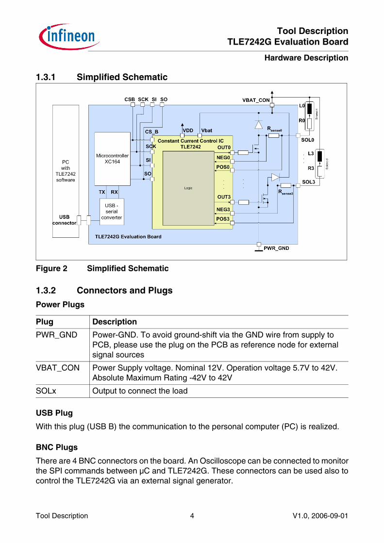
1.3.1 Simplified Schematic
Figure 2 Simplified Schematic
1.3.2 Connectors and Plugs
Power Plugs
USB Plug
With this plug (USB B) the communication to the personal computer (PC) is realized.
BNC Plugs
There are 4 BNC connectors on the board. An Oscilloscope can be connected to monitorthe SPI commands between µC and TLE7242G. These connectors can be used also tocontrol the TLE7242G via an external signal generator.
Plug Description
PWR_GND Power-GND. To avoid ground-shift via the GND wire from supply to PCB, please use the plug on the PCB as reference node for external signal sources
VBAT_CON Power Supply voltage. Nominal 12V. Operation voltage 5.7V to 42V. Absolute Maximum Rating -42V to 42V
SOLx Output to connect the load

Tool DescriptionTLE7242G Evaluation Board
Getting Started
Tool Description 5 V1.0, 2006-09-01
2 Getting StartedThis section describes how to start working with the TLE7242G Evaluation board.
PC System Requirements: NT, 2000 or XP
2.1 Connecting the board
1. Supply the board
Connect a voltage source with 12V to the connectors VBAT_CON (+) and
PWR_GND (-) of the board. The current consumption should be about 200mA.
2. Check jumpers
Please check the jumpers on the TLE7242G Evaluation board. JP1, JP2, JP4, JP5 (3pin jumper, connect the 2 pins on the right) and JP7 (3 pin jumper, connect the upper 2pins) should be mounted (closed).
If the board is properly supplied, LED D4 on the TLE7242G Evaluation board will flash.LED D9 and LED D10 will flash on the XC164CM Modul. In addition to this, LED D15 onthe TLE7242G Evaluation board and LED D5 on the XC164CM Modul will blink.
3. Connect USB cable
Connect the USB cable to the USB connector on the TLE7242G Evaluation board andto the PC.
2.2 Installing PC software
2.2.1 Install driver
To enable USB communication with the board, a device driver has to be installed (FTDIUSB-serial-chip).
After connecting the USB cable the "Found New Hardware"- window will appear. If thewindow will not appear you maybe already have the USB driver installed on your PC. Inthis case refer to Chapter 2.2.2.
Tool DescriptionTLE7242G Evaluation Board
Getting Started
Tool Description 6 V1.0, 2006-09-01
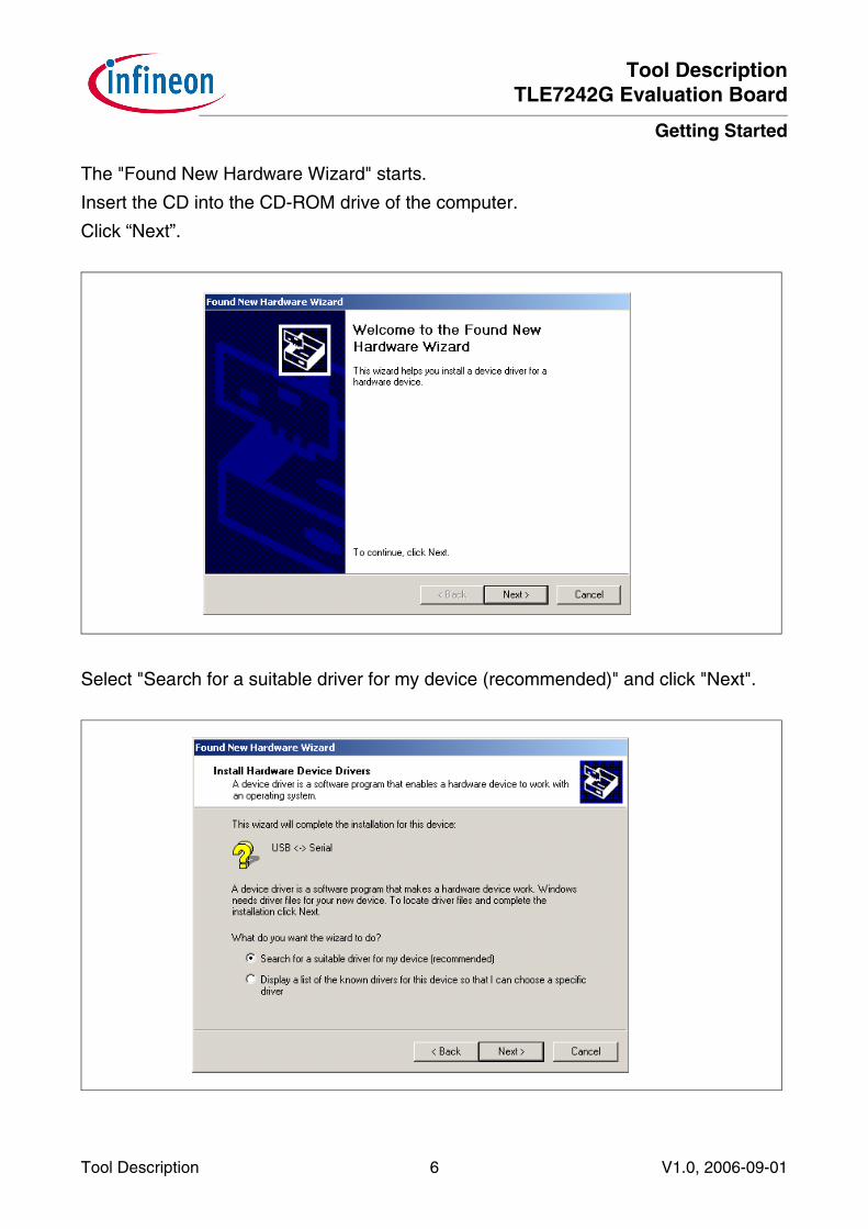
The "Found New Hardware Wizard" starts.
Insert the CD into the CD-ROM drive of the computer.
Click “Next”.
Select "Search for a suitable driver for my device (recommended)" and click "Next".

Tool DescriptionTLE7242G Evaluation Board
Getting Started
Tool Description 7 V1.0, 2006-09-01
The driver files are located on the CD- ROM. Select "CD- ROM drives" and click "Next".
Specify the path to the driver files. Click "Browse".
Tool DescriptionTLE7242G Evaluation Board
Getting Started
Tool Description 8 V1.0, 2006-09-01
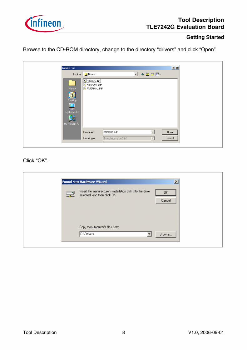
Browse to the CD-ROM directory, change to the directory “drivers” and click “Open”.
Click “OK”.

Tool DescriptionTLE7242G Evaluation Board
Getting Started
Tool Description 9 V1.0, 2006-09-01
Click “Next”.
Click “Finish”.
A second installation window opens, please proceed in the same way as shown above(Chapter 2.2.1).

Tool DescriptionTLE7242G Evaluation Board
Getting Started
Tool Description 10 V1.0, 2006-09-01
2.2.2 Install software
The TLE7242G Evaluation Board is intended to be used in conjunction with the PC-software “Infineon TLE7242_SPI_2_4”. Current version during creation of this documentis 2_4. Please take a look in the file TLE7242G_Evaluation_Kit_Revision_History.txt tosee if there is a newer software version already available. The latest software version isincluded on the CD.
The PC sends serial commands over a USB cable to the board. The USB-to-serialconverter provides standard “RS232” signals to the µC. The µC processes thecommands. It acts as SPI master, the TLE7242G as SPI slave. Diagnosis from theTLE7242G diagnosis will be received by the controller and sent back to the PC.
Installation Instructions
1. Insert the TLE7242G Evaluation Board CD into the CD-ROM drive of the computerand change to the folder: Installer
2. Start the file setup.exe3. Follow the instructions of the setup program.
Note: Administrator permission for the PC is required for successful installation.
Tool DescriptionTLE7242G Evaluation Board
Getting Started
Tool Description 11 V1.0, 2006-09-01
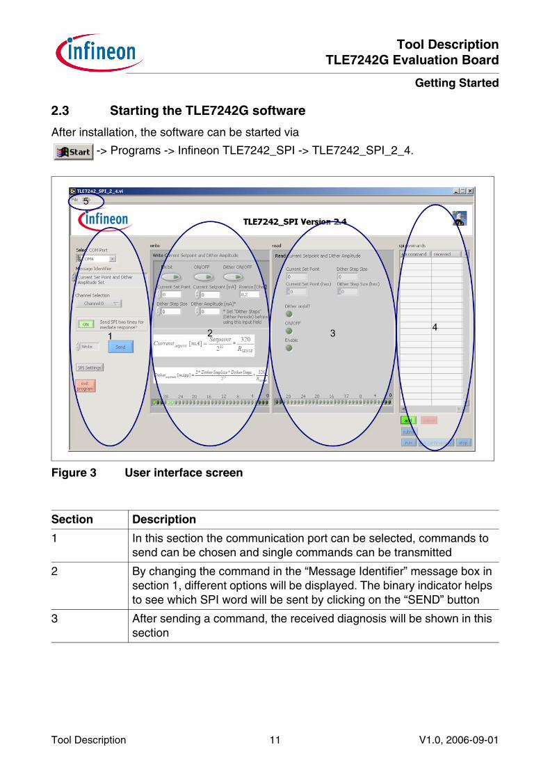
2.3 Starting the TLE7242G software
After installation, the software can be started via
-> Programs -> Infineon TLE7242_SPI -> TLE7242_SPI_2_4.
Figure 3 User interface screen
Section Description
1 In this section the communication port can be selected, commands to send can be chosen and single commands can be transmitted
2 By changing the command in the “Message Identifier” message box in section 1, different options will be displayed. The binary indicator helps to see which SPI word will be sent by clicking on the “SEND” button
3 After sending a command, the received diagnosis will be shown in this section
Tool DescriptionTLE7242G Evaluation Board
Getting Started
Tool Description 12 V1.0, 2006-09-01
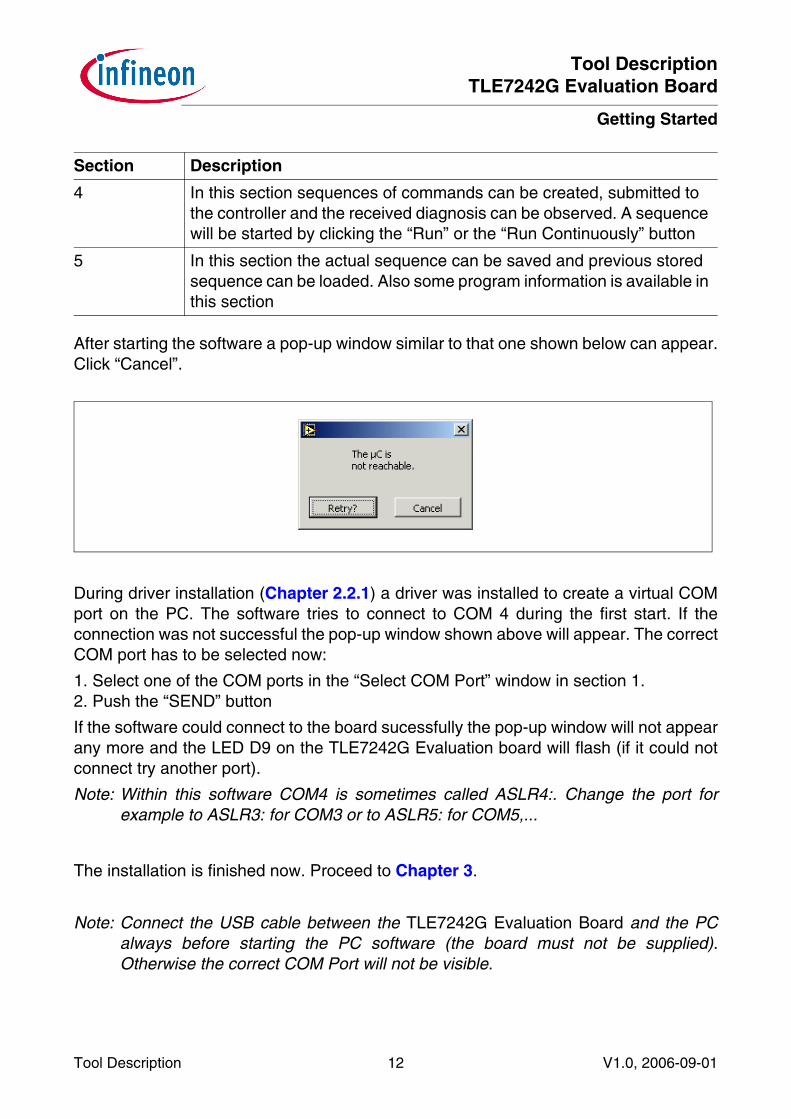
After starting the software a pop-up window similar to that one shown below can appear.Click “Cancel”.
During driver installation (Chapter 2.2.1) a driver was installed to create a virtual COMport on the PC. The software tries to connect to COM 4 during the first start. If theconnection was not successful the pop-up window shown above will appear. The correctCOM port has to be selected now:
1. Select one of the COM ports in the “Select COM Port” window in section 1. 2. Push the “SEND” button
If the software could connect to the board sucessfully the pop-up window will not appearany more and the LED D9 on the TLE7242G Evaluation board will flash (if it could notconnect try another port).
Note: Within this software COM4 is sometimes called ASLR4:. Change the port forexample to ASLR3: for COM3 or to ASLR5: for COM5,...
The installation is finished now. Proceed to Chapter 3.
Note: Connect the USB cable between the TLE7242G Evaluation Board and the PCalways before starting the PC software (the board must not be supplied).Otherwise the correct COM Port will not be visible.
4 In this section sequences of commands can be created, submitted to the controller and the received diagnosis can be observed. A sequence will be started by clicking the “Run” or the “Run Continuously” button
5 In this section the actual sequence can be saved and previous stored sequence can be loaded. Also some program information is available in this section
Section Description
Tool DescriptionTLE7242G Evaluation Board
Application Examples
Tool Description 13 V1.0, 2006-09-01
3 Application Examples
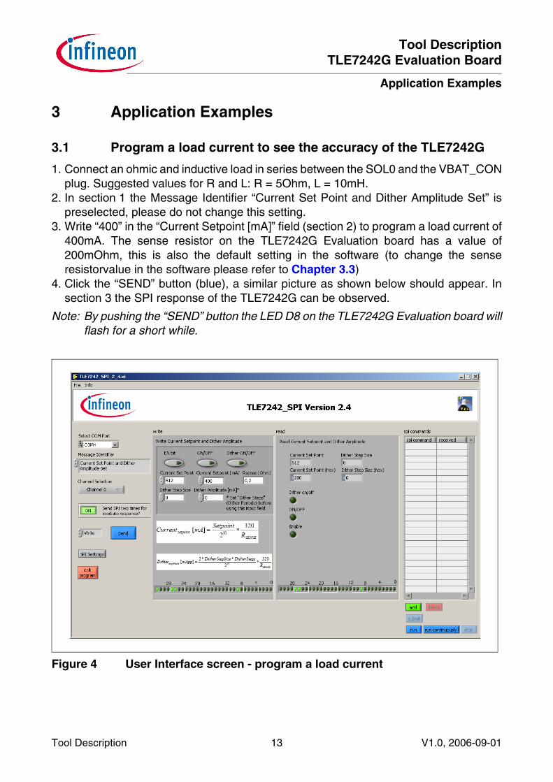
3.1 Program a load current to see the accuracy of the TLE7242G
1. Connect an ohmic and inductive load in series between the SOL0 and the VBAT_CONplug. Suggested values for R and L: R = 5Ohm, L = 10mH.
2. In section 1 the Message Identifier “Current Set Point and Dither Amplitude Set” ispreselected, please do not change this setting.
3. Write “400” in the “Current Setpoint [mA]” field (section 2) to program a load current of400mA. The sense resistor on the TLE7242G Evaluation board has a value of200mOhm, this is also the default setting in the software (to change the senseresistorvalue in the software please refer to Chapter 3.3)
4. Click the “SEND” button (blue), a similar picture as shown below should appear. Insection 3 the SPI response of the TLE7242G can be observed.
Note: By pushing the “SEND” button the LED D8 on the TLE7242G Evaluation board willflash for a short while.
Figure 4 User Interface screen - program a load current

Tool DescriptionTLE7242G Evaluation Board
Application Examples
Tool Description 14 V1.0, 2006-09-01
Observe the SPI communication signals between the µC and the TLE7242G
1. Connect an oscilloscope to the BNC connectors of the TLE7242G Evaluation board.Alternatively, a oscilloscope with voltage probes connected to the test points (CS_B,SCK, SI, SO) next to the TLE7242G device can be used.
Figure 5 TLE7242G SPI communication
On the screen above it can be seen that the same command was sent two times. TheµC software sends the command two times automatically.
Reason: The TLE7242G always sends the diagnosis word requested during the previousSPI command. The second SO word includes the requested diagnosis word. Thisdiagnosis word is also displayed in the user interface of the Infineon TLE7242_SPI_2_4software, section 3 (see Figure 4). In the case shown above both SO diagnosis wordsare the same (because the same command was sent before).
Note: This software feature can be disabled by changing the status of the “Send SPI twotimes for immediate response” button from “On” to “Off”.
See the TLE7242G current control behavior
1. Connect an oscilloscope voltage probe to the test point SOL0 to monitor the voltageat the load
2. Connect an oscilloscope current probe to the cable connected to the load.

Tool DescriptionTLE7242G Evaluation Board
Application Examples
Tool Description 15 V1.0, 2006-09-01
3. For more precise DC measurements, connect a high precision Multimeter (forexample Keithley 2001) in the load current path. Such a multimeter is necessary tomonitor the load current with high accurracy (0.1%).
An oscilloscope screen similar to the example below can be observed.
Figure 6 Current control behavior
If the same command will be sent again the current will not rise again as shown above(because the current is already programmed to 400mA).
How to reset the current to 0mA again:
- Program 0mA using the “Average current Setpoint (mA)” field or
- Push the “RESET” button on the TLE7242G Evaluation board. This causes two actions:
1. Resets the µC
Note: This action does not reset the TLE7242G
2. The µC will program a load current of 0 mA on all 4 channels automatically aftercoming out of a reset condition
Tool DescriptionTLE7242G Evaluation Board
Application Examples
Tool Description 16 V1.0, 2006-09-01
3.2 Programming a sequence
With this software it is possible to program sequences in the memory of the µC. Customsequences can be created by pushing the “Add” button in the TLE7242G user interface(section 4 in Figure 3). An example sequence can be found on the CD, how to use it seethe description below:
1. Click “Sequence” and then “Load” (section 5 in Figure 3)2. Browse to the folder “sequences” on the CD3. Select the file with the name “TLE7242_step.seq” and Click “Ok”. The sequence will
be loaded in section 44. Click “Submit” to transfer the sequence to the memory of the µC5. Click “Run” to command the µC sending the sequence to the TLE7242G
Note: After the sequence has started, it cannot be interrupted. It must be completedbefore being allowed to start again.
During the sequence runs real time behavior between the µC and the TLE7242G can beassumed. After the sequence has completed, all diagnosis words stored in the memoryof the µC will be sent to the PC and displayed in section 4.
To test the diagnosis disconnect the load connected at SOL0. Choose the MessageIdentifier “Diagnostic Read” and click “SEND”. The “Open Load on” or the “Open Loadoff” indicator of Channel 0 in section 3 will flash.
Note: Please do not disconnect the load during a high load current is programmed. Thiscan cause voltage spikes on the supply line which can reset the FT232BL USB-to-serial converter. Under certain circumstances the PC software will crash by thiseffect.

Tool DescriptionTLE7242G Evaluation Board
Application Examples
Tool Description 17 V1.0, 2006-09-01
Figure 7 User interface screen - loading a sequence

Tool DescriptionTLE7242G Evaluation Board
Application Examples
Tool Description 18 V1.0, 2006-09-01
Figure 8 Load current during example sequence
Every current step in Figure 8 has a duration of 50 ms. This is the default value afterstarting the software. It can be changed by clicking the button “SPI settings” in thesoftware. It is also possible to change the SPI speed here. The values have to be readas described below:
Figure 9 Setting SPI Speed and SPI Command Delay

Tool DescriptionTLE7242G Evaluation Board
Application Examples
Tool Description 19 V1.0, 2006-09-01
3.3 Change Rsense value and CLK setting in the PC software
It is possible to change the Rsense value for Channel 0 to 3 and also the Clock frequencywhich is used by the Infineon TLE7242_SPI_2_4 PC software to calculate theprogrammed currents and the timings.
Note: It is only necessary to change these settings if you like to solder a different senseresistor than 200mOhm on the board or if you want to use a different Clockfrequency than 20 MHz.
1. Open the file Constants.ini, it can be found in the installation directory of the InfineonTLE7242_SPI_2_4 software.
Typical directory: C:\Program Files\TLE7242_SPI_2_4\Constants.ini)
2. Change the settings as needed to adapt to different configurations of the TLE7242GEvaluation Board (see also screenshot below).
Tool DescriptionTLE7242G Evaluation Board
Schematic
Tool Description 20 V1.0, 2006-09-01
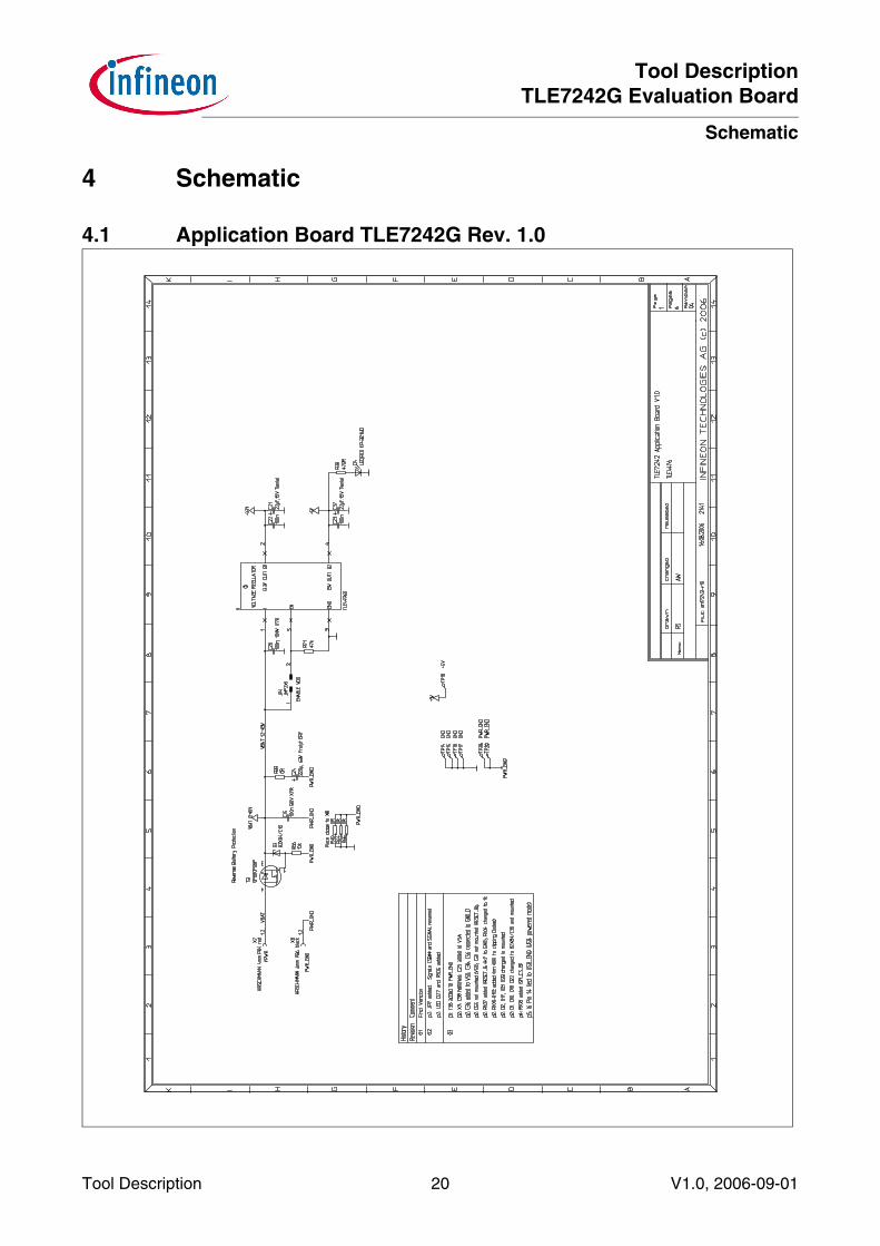
4 Schematic
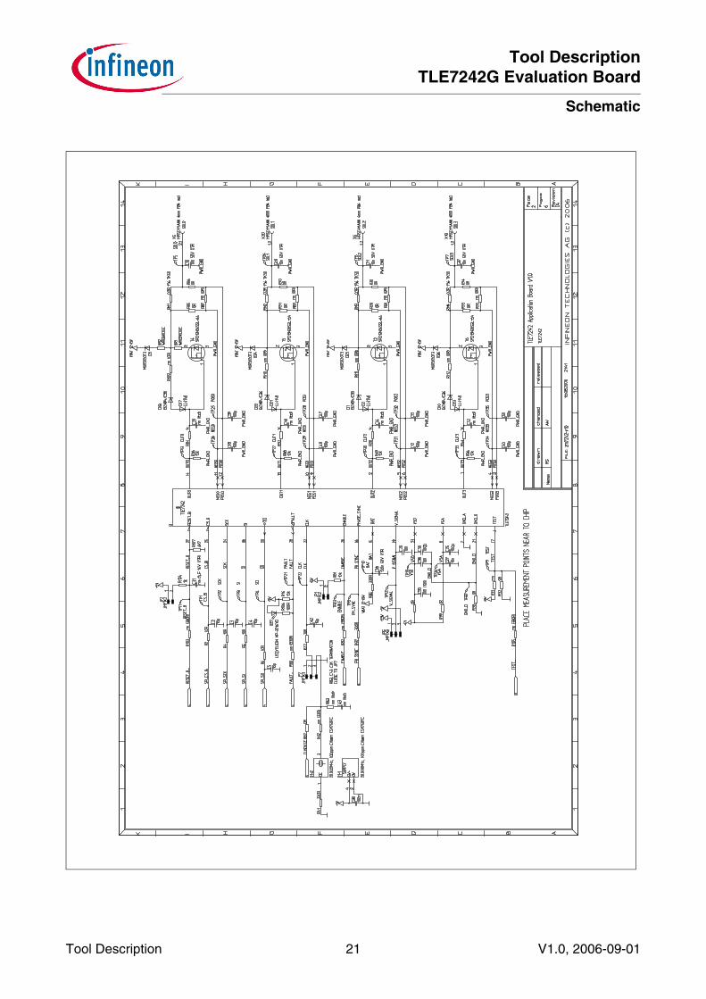
4.1 Application Board TLE7242G Rev. 1.0
Tool DescriptionTLE7242G Evaluation Board
Schematic
Tool Description 21 V1.0, 2006-09-01

Tool DescriptionTLE7242G Evaluation Board
Schematic
Tool Description 22 V1.0, 2006-09-01

Tool DescriptionTLE7242G Evaluation Board
Schematic
Tool Description 23 V1.0, 2006-09-01

Tool DescriptionTLE7242G Evaluation Board
Schematic
Tool Description 24 V1.0, 2006-09-01
Tool DescriptionTLE7242G Evaluation Board
Schematic
Tool Description 25 V1.0, 2006-09-01

Tool DescriptionTLE7242G Evaluation Board
Schematic
Tool Description 26 V1.0, 2006-09-01
4.2 XC164CM Module

Tool DescriptionTLE7242G Evaluation Board
Schematic
Tool Description 27 V1.0, 2006-09-01

Tool DescriptionTLE7242G Evaluation Board
Schematic
Tool Description 28 V1.0, 2006-09-01
Edition 2006-09-01Published byInfineon Technologies AG81726 München, Germany© Infineon Technologies AG 10/24/06.All Rights Reserved.
LEGAL DISCLAIMERTHE INFORMATION GIVEN IN THIS APPLICATION NOTE IS GIVEN AS A HINT FOR THE IMPLEMENTATION OF THE INFINEON TECHNOLOGIES COMPONENT ONLY AND SHALL NOT BE REGARDED AS ANY DESCRIPTION OR WARRANTY OF A CERTAIN FUNCTIONALITY, CONDITION OR QUALITY OF THE INFINEON TECHNOLOGIES COMPONENT. THE RECIPIENT OF THIS APPLICATION NOTE MUST VERIFY ANY FUNCTION DESCRIBED HEREIN IN THE REAL APPLICATION. INFINEON TECHNOLOGIES HEREBY DISCLAIMS ANY AND ALL WARRANTIES AND LIABILITIES OF ANY KIND (INCLUDING WITHOUT LIMITATION WARRANTIES OF NON-INFRINGEMENT OF INTELLECTUAL PROPERTY RIGHTS OF ANY THIRD PARTY) WITH RESPECT TO ANY AND ALL INFORMATION GIVEN IN THIS APPLICATION NOTE.
InformationFor further information on technology, delivery terms and conditions and prices please contact your nearest Infineon Technologies Office (www.infineon.com).
WarningsDue to technical requirements components may contain dangerous substances. For information on the types in question please contact your nearest Infineon Technologies Office.Infineon Technologies Components may only be used in life-support devices or systems with the express written approval of Infineon Technologies, if a failure of such components can reasonably be expected to cause the failure of that life-support device or system, or to affect the safety or effectiveness of that device or system. Life support devices or systems are intended to be implanted in the human body, or to support and/or maintain and sustain and/or protect human life. If they fail, it is reasonable to assume that the health of the user or other persons may

Qualität hat für uns eine umfassende Bedeutung. Wir wollen allen Ihren Ansprüchen in der bestmöglichen Weise gerecht werden. Es geht uns also nicht nur um die Produktqualität – unsere Anstrengungen gelten gleichermaßen der Lieferqualität und Logistik, dem Service und Support sowie allen sonstigen Beratungs- und Betreuungsleistungen.
Dazu gehört eine bestimmte Geisteshaltung unserer Mitarbeiter. Total Quality im Denken und Handeln gegenüber Kollegen, Lieferanten und Ihnen, unserem Kunden. Unsere Leitlinie ist jede Aufgabe mit „Null Fehlern“ zu lösen – in offener Sichtweise auch über den eigenen Arbeitsplatz hinaus – und uns ständig zu verbessern.
Unternehmensweit orientieren wir uns dabei auch an „top“ (Time Optimized Processes), um Ihnen durch größere Schnelligkeit den entscheidenden Wettbewerbsvorsprung zu verschaffen.
Geben Sie uns die Chance, hohe Leistung durch umfassende Qualität zu beweisen.
Wir werden Sie überzeugen.
Quality takes on an all-encompassing significance at Semiconductor Group. For us it means living up to each and every one of your demands in the best possible way. So we are not only concerned with product quality. We direct our efforts equally at quality of supply and logistics, service and support, as well as all the other ways in which we advise and attend to you.
Part of this is the very special attitude of our staff. Total Quality in thought and deed, towards co-workers, suppliers and you, our customer. Our guideline is “do everything with zero defects”, in an open manner that is demonstrated beyond your immediate workplace, and to constantly improve.
Throughout the corporation we also think in terms of Time Optimized Processes (top), greater speed on our part to give you that decisive competitive edge.
Give us the chance to prove the best of performance through the best of quality – you will be convinced.
h t t p : / / w w w . i n f i n e o n . c o m
Total Quality Management
Published by Infineon Technologies AG