tlc59116evm-390 user's guide - ti.com · 4 tlc59116evm-390 schematic - sheet 2 ... minimize...
TRANSCRIPT

User's GuideSLVU296–March 2009
TLC59116EVM-390
This user’s guide describes the characteristics, setup, and use of the TLC59116EVM-390 EvaluationModule (EVM). This EVM helps the user evaluate the features of the Texas Instruments TLC59116, whichis an I2C bus-controlled, 16-channel, constant-current LED driver. This user’s guide includes set-upinstructions, a schematic diagram, a bill of materials, printed-circuit board layout drawings, and softwareinstructions.
Contents1 Introduction ................................................................................................................... 2
1.1 Requirements ....................................................................................................... 22 Setup .......................................................................................................................... 3
2.1 Input / Output Connector Descriptions ........................................................................... 32.2 Software Setup...................................................................................................... 42.3 Hardware Setup .................................................................................................... 5
3 Operation ..................................................................................................................... 53.1 Operation ............................................................................................................ 5
4 Schematics, Board Layouts, and Bills of Materials...................................................................... 94.1 Schematics ......................................................................................................... 104.2 Layouts ............................................................................................................. 134.3 Bills of Materials ................................................................................................... 21
5 Related Documentation From Texas Instruments ..................................................................... 21
List of Figures
1 Driver Board and LED Board Connections ............................................................................... 32 TLC59116 EVM Software Start-up Screen............................................................................... 63 TLC59116EVM-390 Schematic - Sheet 1............................................................................... 104 TLC59116EVM-390 Schematic - Sheet 2............................................................................... 115 RGBLEDEVM-249 Schematic ............................................................................................ 126 TLC59116EVM-390 Assembly Layer Routing.......................................................................... 137 Top Layer Routing ......................................................................................................... 148 Layer 2 Routing............................................................................................................. 159 Layer 3 Routing............................................................................................................. 1610 Bottom Layer Routing...................................................................................................... 1711 Assembly Layer Routing .................................................................................................. 1812 Top Layer Routing ......................................................................................................... 1913 Bottom Layer Routing...................................................................................................... 20
List of Tables
1 HPA390 Bill of Materials................................................................................................... 212 HPA249A Bill of Materials................................................................................................. 21
Windows, Internet Explorer are trademarks of Microsoft Corporation.Verisign is a trademark of Verisign, Inc.
SLVU296–March 2009 TLC59116EVM-390 1Submit Documentation Feedback

1 Introduction
1.1 Requirements
1.1.1 Software
1.1.2 Host Computer
1.1.3 Power Supply Requirements
1.1.4 Printed-Circuit Board Assemblies
Introduction www.ti.com
The TLC59116 is an I2C bus-controlled, 16-channel LED driver that is optimized for red/green/blue/amber(RGBA) color mixing and backlight application for amusement products. Each LED output has its own 8-bitresolution (256 steps), fixed-frequency, individual PWM controller that operates at 97 kHz, with a dutycycle that is adjustable from 0% to 99.6%. The individual PWM controller allows each LED to be set to aspecific brightness value. An additional 8-bit resolution (256 steps) group PWM controller has both a fixedfrequency of 190 Hz and an adjustable frequency between 24 Hz to once every 10.73 seconds, with aduty cycle that is adjustable from 0% to 99.6%. The group PWM controller dims or blinks all LEDs with thesame value.
In order to operate this EVM, the following components must be connected and properly configured. Allcomponents, software, and connectors are supplied in the EVM except for the host computer and the dcpower supply.
Texas Instruments has provided a compact disc in the EVM kit that contains the software necessary toevaluate the TLC59116EVM. Check the TLC59116 product folder on the Texas Instruments Web site(www.ti.com) for updates to the software.
A personal computer (PC) with a USB port is required to operate this EVM. The TLC59116 software runson the PC and communicates with the EVM via the PC’s USB port.
Personal Computer Requirements• Windows™ 2000 or Windows XP operating system• USB port• Minimum of 30 MB of free hard disk space (100 MB recommended)• Minimum of 256 MB of RAM
DC power supply capable of delivering 3.3 V at 1.5 A is required to power the EVM
The TLC59116EVM-390 kit contains two printed-circuit boards (PCB): HPA390 (Driver board) andHPA249 (LED board). The Driver board contains the TLC59116 integrated circuits (IC) and their requiredexternal components. This board contains several jumpers and connectors that enable you to customizethe board for specific operating conditions. The LED board contains 16 LEDs, each with three individualLEDs in the same package: a red, a green, and a blue LED. The orderable Texas Instruments partnumber for this PCB is RGBLEDEVM-249. The EVM is designed to directly drive the LED board. Thecustomer can also remove the LED board to drive a custom LED board. Figure 1 shows how these boardsare connected.
2 TLC59116EVM-390 SLVU296–March 2009Submit Documentation Feedback

USB to GPIOBox
TLC59116
TLC59116
TLC59116
USB
LED Driver Board (HPA390)
LED Board
(RGBLEDEVM-249)
816
16
16
Host Computer
2 Setup
2.1 Input / Output Connector Descriptions
2.1.1 J1 – USB to GPIO Box
2.1.2 J2 – LED Connector
2.1.3 J3 – LED Connector
2.1.4 J4 – VIN
www.ti.com Setup
Figure 1. Driver Board and LED Board Connections
The user’s computer connects to the LED Driver board with a USB cable and communicates through anI2C bus via the USB to GPIO box. The TLC59116 ICs exchange data with the host computer through theUSB and drive the LED board accordingly.
This section describes the jumpers and connectors on the EVM as well as how to properly connect, setup, and use the TLC59116EVM-390.
This box connects the EVM to the host PC’s USB port through an I2C Bus.
This connector mates to the HPA249 LED board. The user can also connect a custom board to thisconnector with a standard 30-pin ribbon cable with 0.1-inch pin-to-pin spacing. In order to minimize strayinductance and ringing on the output traces, connections to this connector must be as short as possible.
This connector mates to the HPA249 LED board. The user can also connect a custom board to thisconnector with a standard 30-pin ribbon cable with 0.1-inch pin-to-pin spacing. In order to minimize strayinductance and ringing on the output traces, connections to this connector must be as short as possible.
This is the positive input supply to the EVM. Connect the dc power supply (at least 3.3 V) to this end. Tominimize power dissipation, the input voltage must be as low as possible. The leads to the input supplymust be twisted and kept as short as possible to minimize EMI transmission.
SLVU296–March 2009 TLC59116EVM-390 3Submit Documentation Feedback

2.1.5 J5 – GND Connector
2.1.6 J6 – Input Power Connector
2.1.7 JP1 – Red LED
2.1.8 JP2 – Green LED
2.1.9 JP3 – BLUE LED
2.2 Software Setup
Setup www.ti.com
This is the return for the input supply to the EVM. The leads to the input supply must be twisted and keptas short as possible to minimize EMI transmission.
This is a right-angle miniature power jack with a 3.5-mm-diameter connection. The user uses thisconnector to supply input power to the EVM from an ac-to-dc power adapter. The outer pin on theconnector is connected directly to J8 (GND). When using an ac-to-dc power adapter, ensure that thepower adapter’s output voltage is stable and does not drop below 5 V when loaded.
This jumper must be shorted to connect the red LED driver’s OUT15 pin to the red LED. This jumper canbe opened to measure the current flowing into the OUT15 pin from the red LED. In this EVM, the defaultcurrent is set to approximately 19 mA using Rext = 931 Ω.
This jumper must be shorted to connect the green LED driver’s OUT15 pin to the green LED. This jumpercan be opened to measure the current flowing into the OUT15 pin from the green LED. In this EVM, thedefault current is set to approximately 19 mA using Rext = 931 Ω.
This jumper must be shorted to connect the blue LED driver’s OUT15 pin to the blue LED. This jumpercan be opened to measure the current flowing into the OUT15 pin from the blue LED. In this EVM, thedefault current is set to approximately 19 mA using Rext = 931 Ω.
If installing from a compact disc (CD), insert the CD and run Setup.exe, following all the prompts to installthe software .
If installing from the World Wide Web, go to the URL www.ti.com.
Note: This installation page is best viewed with Microsoft Internet Explorer™ browser (It may notwork correctly with other browsers).
When you click on the install button, your PC gives you a security warning and asks if you want to installthis application. Select Install to proceed.
With both types of installation, the software attempt to install the Microsoft Dot Net Framework 2.0 (if it isnot already installed). This framework is required for the software to run.
After installation, the software runs automatically.
During future use of the software, it may prompt you to install a new version if it becomes available on theTI Web site.
Note: Verisign™ code signing is used to prevent any malicious code from changing thisapplication. If at any time in the future the binaries are modified, the code will no longerattempt to run.
TLC59116EVM-3904 SLVU296–March 2009Submit Documentation Feedback
2.3 Hardware Setup
3 Operation
3.1 Operation
3.1.1 Running the Software
www.ti.com Operation
Install one shorting jumper each across JP1, JP2, and JP3. Connect the LED board (HPA249) to the LEDDriver board (HPA390).
Connect the LED Driver board to the host computer using the USB interface adapter.
Using either the J4 and J5 input power connectors or the J6 power jack connector, connect an inputvoltage to the TLC59116EVM board. The TLC59116 uses an input voltage between 5 V and 17 V. Set theinput supply current limit to 1.5 A. If using a laboratory supply, use at least 18 AWG twisted wire. Note thatsome ac/dc power adapters do not provide clean power. Ensure that the input voltage is well regulated toavoid intermittent communication problems.
CAUTIONHot plugging the input supply with long leads can generate transients on theinput supply bus that exceed the maximum ratings of the EVM. The inputsupply must be connected before it is turned on.
Turn on the input supply voltage.
This section provides instructions on how to turn on the TLC59116EVM and operate the software.
The user can now run the GUI software on the host computer to change the LED programming with theeasy-to-use graphical interface.
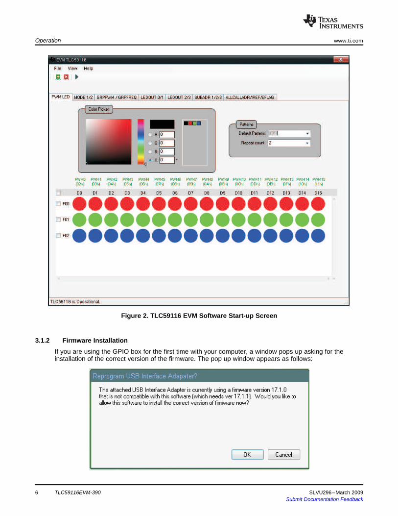
Click on the TLC59116 EVM software icon on the host computer to start the software. If the host computershows no icon, then use the start button in the lower left corner of the screen to browse the programfolders to find the software. The default directory for software installation is Program Files, TexasInstruments TLC59116 EVM Software. The executable file name is TLC59116 EVM Software.exe. Oncestarted, the software checks the firmware in the DSP board to ensure that it is compatible with thesoftware. If the firmware is incompatible, the software gives the user instructions on how to reprogram it.Once the software is started and communication is established between the GUI and the EVM, the usercan use the graphical interface to program the LEDs. If the EVM is properly connected, the softwarescreen looks like Figure 2 when first opened.
SLVU296–March 2009 TLC59116EVM-390 5Submit Documentation Feedback
3.1.2 Firmware Installation
Operation www.ti.com
Figure 2. TLC59116 EVM Software Start-up Screen
If you are using the GPIO box for the first time with your computer, a window pops up asking for theinstallation of the correct version of the firmware. The pop up window appears as follows:
6 TLC59116EVM-390 SLVU296–March 2009Submit Documentation Feedback
3.1.3 Software Features
3.1.3.1 Patterns
www.ti.com Operation
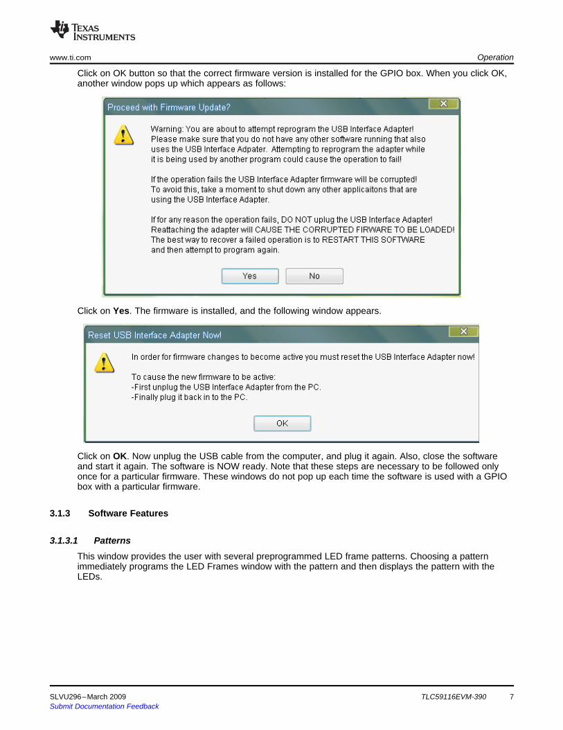
Click on OK button so that the correct firmware version is installed for the GPIO box. When you click OK,another window pops up which appears as follows:
Click on Yes. The firmware is installed, and the following window appears.
Click on OK. Now unplug the USB cable from the computer, and plug it again. Also, close the softwareand start it again. The software is NOW ready. Note that these steps are necessary to be followed onlyonce for a particular firmware. These windows do not pop up each time the software is used with a GPIObox with a particular firmware.
This window provides the user with several preprogrammed LED frame patterns. Choosing a patternimmediately programs the LED Frames window with the pattern and then displays the pattern with theLEDs.
SLVU296–March 2009 TLC59116EVM-390 7Submit Documentation Feedback

3.1.3.2 Color Picker
3.1.3.3 LED Frames
3.1.3.4 File – Save and Load
3.1.3.5 View – LED Display Mode
3.1.3.6 Information Bar – EVM Status
3.1.3.7 Other Tabs
Operation www.ti.com
This window allows the user to choose the red, green, and blue PWM value for each LED. The softwareprovides three options for choosing the color for an LED. The user can manually enter the PWM valuesinto the three text boxes, use the mouse to pick colors from the color bars, or use the mouse to click on acolor from the custom color pallet. The color chosen in the Color Picker window is immediately displayedin the LEDs that are highlighted in the LED Frames window. The user can add custom colors to the palletby dragging the current color to the custom color pallet. Custom colors can be deleted by right-clicking onthe color to be removed.
This window shows the individual frames that are displayed by the LEDs. Changes to the current color inthe Color Picker automatically update the selected LEDs or frames in the LED Frames window. Changesin the LED Frame are immediately written to the EVM and displayed by the LEDs. The check boxes alloweasy selection of an entire frame or all frames. The user can select a single LED or select multiple LEDsby holding the <shift> or <ctrl> buttons on the host computer’s keyboard while clicking on the LEDs. TheRepeat box in the right side of the LED Frames window tells the EVM how many times to display thatframe before moving to the next frame. Note that due to manufacturing tolerances in LED brightness andcolor, the LED colors displayed in this window are only approximate to the actual LED color on the EVM.
This tab allows the user to save and load custom frames. The file also saves all user-selectable settingssuch as operating frequency and Global Brightness settings.
When Solid display mode is chosen, the pixel in the LED Frames window shows the LED pixels and theirapproximate color on the EVM. This color is generated by the mixing of the three individual LED colors.When RGB display mode is chosen, the pixel shows the relative intensity of each individual LED thatmakes up each pixel.
The information bar displays whether or not the GUI detects the EVM hardware.
In addition to the options previously described, additional tabs as shown in the following figure. These tabsprovide the user with full control of all the TLC59116 internal registers. The tab names correspond to theregister names as defined in the data sheet.
8 TLC59116EVM-390 SLVU296–March 2009Submit Documentation Feedback

4 Schematics, Board Layouts, and Bills of Materials
www.ti.com Schematics, Board Layouts, and Bills of Materials
Each tab contains a register as shown in the following illustration.
You can set or reset the 8 bits manually by clicking on them, and then clicking on the write button to theleft of these bits. To determine the current status of a register, click the leftmost read button, and theregister shows its current status.
In some particular registers, some predefined settings are indicated below the registers. An explanation ofthese particular cases follow.
Particular Cases:1. Mode1/2: In this tab, in addition to the manual control of the registers, users can directly control the
registers for some predefined tasks like:a. Response to I2C bus addressb. Normal/Low Power modec. Enable/Clear status flagd. Dimming/Blinkinge. Outputs change
All these conditions are clearly indicated below the registers.2. GRPPWM/GRPFREQ: The Group PWM duty cycle and the Group PWM frequency can be directly set
by using the seek button shown above the respective register. The seek button appears as follows:
3. LEDOUT0/1/2/3: In the two tabs LEDOUT0/1 and LEDOUT2/3 , in addition to directly setting theindividual bits from the registers, four options for every LED are given below the register. The fouroptions are:a. Default Power Stateb. Brightness and Dimming not controlledc. Brightness controlled by using PWMd. Brightness and Dimming controlled
When a user selects any of these conditions, the register bits are arranged for the selectedparticular condition.
4. IREF: In the IREF register, the current multiplier and the HC can be set directly to either high or low,using the button below IREF registers.
All the preceding settings are to be done separately for the Red part, the Green part, and the Blue Part,which is selected from the drop-down box at the very top of the window.
This section provides the TLC59116EVM-390 and RGBLEDEVM-249 schematics, board layouts, and billsof materials illustrations.
SLVU296–March 2009 TLC59116EVM-390 9Submit Documentation Feedback

4.1 Schematics
++
Schematics, Board Layouts, and Bills of Materials www.ti.com
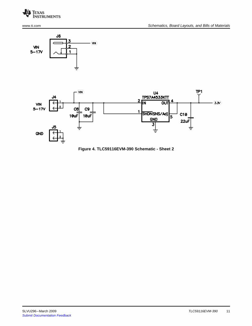
The schematic for TLC59116EVM-390 appears as Figure 3and Figure 4.
Figure 3. TLC59116EVM-390 Schematic - Sheet 1
10 TLC59116EVM-390 SLVU296–March 2009Submit Documentation Feedback
www.ti.com Schematics, Board Layouts, and Bills of Materials
Figure 4. TLC59116EVM-390 Schematic - Sheet 2
SLVU296–March 2009 TLC59116EVM-390 11Submit Documentation Feedback
Schematics, Board Layouts, and Bills of Materials www.ti.com
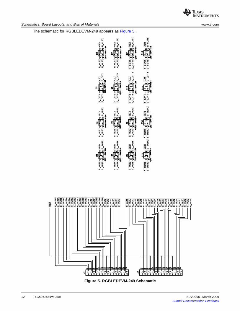
The schematic for RGBLEDEVM-249 appears as Figure 5 .
Figure 5. RGBLEDEVM-249 Schematic
TLC59116EVM-39012 SLVU296–March 2009Submit Documentation Feedback

4.2 Layoutswww.ti.com Schematics, Board Layouts, and Bills of Materials
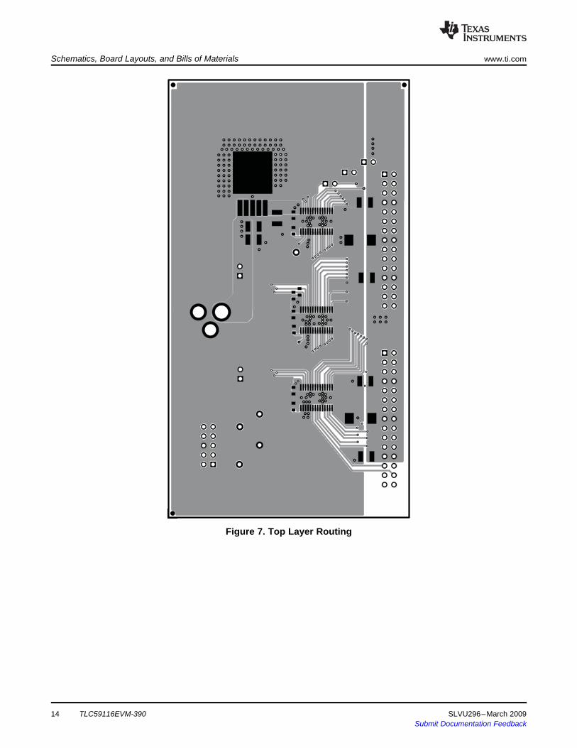
Figure 6 and Figure 10 show the board layout for the TLC59116EVM-390.
Figure 6. TLC59116EVM-390 Assembly Layer Routing
SLVU296–March 2009 TLC59116EVM-390 13Submit Documentation Feedback
Schematics, Board Layouts, and Bills of Materials www.ti.com
Figure 7. Top Layer Routing
TLC59116EVM-39014 SLVU296–March 2009Submit Documentation Feedback

www.ti.com Schematics, Board Layouts, and Bills of Materials
Figure 8. Layer 2 Routing
SLVU296–March 2009 TLC59116EVM-390 15Submit Documentation Feedback
Schematics, Board Layouts, and Bills of Materials www.ti.com
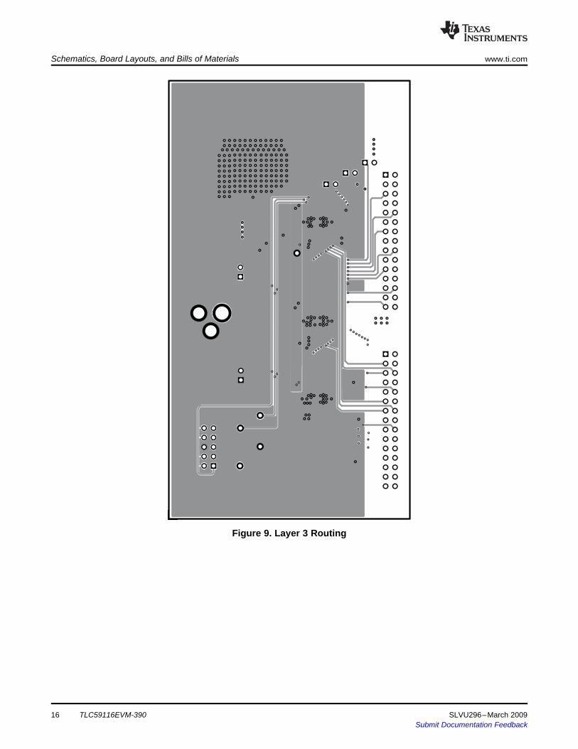
Figure 9. Layer 3 Routing
TLC59116EVM-39016 SLVU296–March 2009Submit Documentation Feedback

www.ti.com Schematics, Board Layouts, and Bills of Materials
Figure 10. Bottom Layer Routing
SLVU296–March 2009 TLC59116EVM-390 17Submit Documentation Feedback

Schematics, Board Layouts, and Bills of Materials www.ti.com
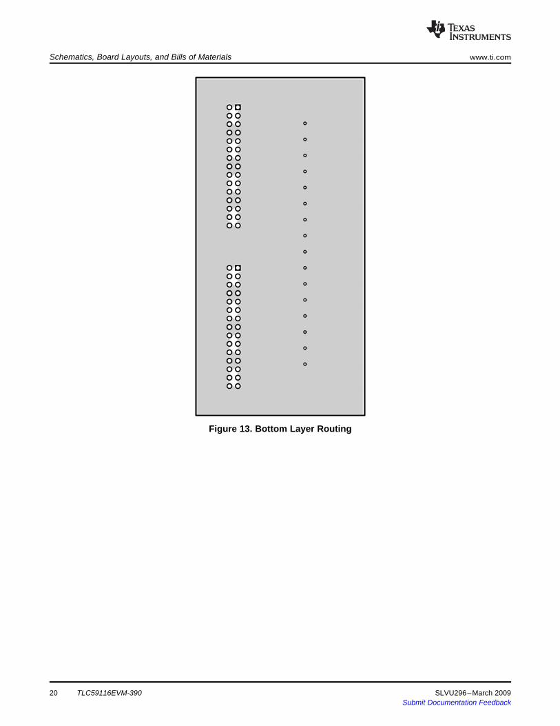
Figure 11 through Figure 13 show the board layout for the LED board, RGBLEDEVM-249.
Figure 11. Assembly Layer Routing
18 TLC59116EVM-390 SLVU296–March 2009Submit Documentation Feedback

www.ti.com Schematics, Board Layouts, and Bills of Materials
Figure 12. Top Layer Routing
SLVU296–March 2009 TLC59116EVM-390 19Submit Documentation Feedback
Schematics, Board Layouts, and Bills of Materials www.ti.com
Figure 13. Bottom Layer Routing
TLC59116EVM-39020 SLVU296–March 2009Submit Documentation Feedback
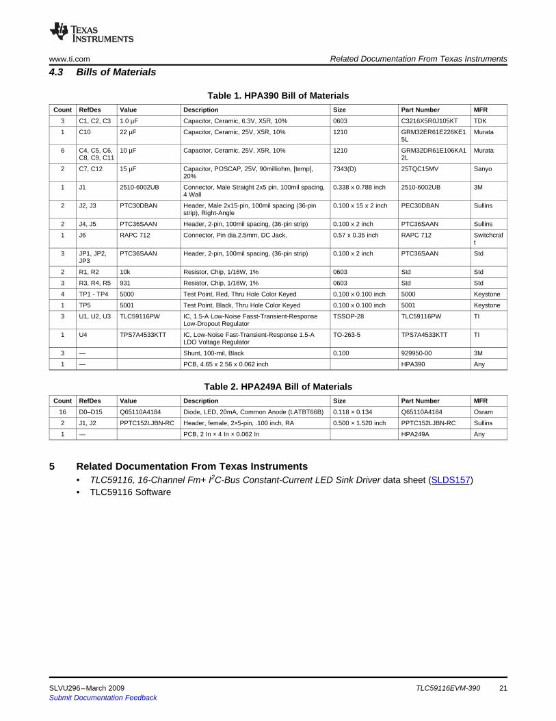
4.3 Bills of Materials
5 Related Documentation From Texas Instruments
www.ti.com Related Documentation From Texas Instruments
Table 1. HPA390 Bill of MaterialsCount RefDes Value Description Size Part Number MFR
3 C1, C2, C3 1.0 µF Capacitor, Ceramic, 6.3V, X5R, 10% 0603 C3216X5R0J105KT TDK
1 C10 22 µF Capacitor, Ceramic, 25V, X5R, 10% 1210 GRM32ER61E226KE1 Murata5L
6 C4, C5, C6, 10 µF Capacitor, Ceramic, 25V, X5R, 10% 1210 GRM32DR61E106KA1 MurataC8, C9, C11 2L
2 C7, C12 15 µF Capacitor, POSCAP, 25V, 90milliohm, [temp], 7343(D) 25TQC15MV Sanyo20%
1 J1 2510-6002UB Connector, Male Straight 2x5 pin, 100mil spacing, 0.338 x 0.788 inch 2510-6002UB 3M4 Wall
2 J2, J3 PTC30DBAN Header, Male 2x15-pin, 100mil spacing (36-pin 0.100 x 15 x 2 inch PEC30DBAN Sullinsstrip), Right-Angle
2 J4, J5 PTC36SAAN Header, 2-pin, 100mil spacing, (36-pin strip) 0.100 x 2 inch PTC36SAAN Sullins
1 J6 RAPC 712 Connector, Pin dia.2.5mm, DC Jack, 0.57 x 0.35 inch RAPC 712 Switchcraft
3 JP1, JP2, PTC36SAAN Header, 2-pin, 100mil spacing, (36-pin strip) 0.100 x 2 inch PTC36SAAN StdJP3
2 R1, R2 10k Resistor, Chip, 1/16W, 1% 0603 Std Std
3 R3, R4, R5 931 Resistor, Chip, 1/16W, 1% 0603 Std Std
4 TP1 - TP4 5000 Test Point, Red, Thru Hole Color Keyed 0.100 x 0.100 inch 5000 Keystone
1 TP5 5001 Test Point, Black, Thru Hole Color Keyed 0.100 x 0.100 inch 5001 Keystone
3 U1, U2, U3 TLC59116PW IC, 1.5-A Low-Noise Fasst-Transient-Response TSSOP-28 TLC59116PW TILow-Dropout Regulator
1 U4 TPS7A4533KTT IC, Low-Noise Fast-Transient-Response 1.5-A TO-263-5 TPS7A4533KTT TILDO Voltage Regulator
3 — Shunt, 100-mil, Black 0.100 929950-00 3M
1 — PCB, 4.65 x 2.56 x 0.062 inch HPA390 Any
Table 2. HPA249A Bill of MaterialsCount RefDes Value Description Size Part Number MFR
16 D0–D15 Q65110A4184 Diode, LED, 20mA, Common Anode (LATBT66B) 0.118 × 0.134 Q65110A4184 Osram
2 J1, J2 PPTC152LJBN-RC Header, female, 2×5-pin, .100 inch, RA 0.500 × 1.520 inch PPTC152LJBN-RC Sullins
1 — PCB, 2 In × 4 In × 0.062 In HPA249A Any
• TLC59116, 16-Channel Fm+ I2C-Bus Constant-Current LED Sink Driver data sheet (SLDS157)• TLC59116 Software
SLVU296–March 2009 TLC59116EVM-390 21Submit Documentation Feedback

EVALUATION BOARD/KIT IMPORTANT NOTICETexas Instruments (TI) provides the enclosed product(s) under the following conditions:This evaluation board/kit is intended for use for ENGINEERING DEVELOPMENT, DEMONSTRATION, OR EVALUATION PURPOSESONLY and is not considered by TI to be a finished end-product fit for general consumer use. Persons handling the product(s) must haveelectronics training and observe good engineering practice standards. As such, the goods being provided are not intended to be completein terms of required design-, marketing-, and/or manufacturing-related protective considerations, including product safety and environmentalmeasures typically found in end products that incorporate such semiconductor components or circuit boards. This evaluation board/kit doesnot fall within the scope of the European Union directives regarding electromagnetic compatibility, restricted substances (RoHS), recycling(WEEE), FCC, CE or UL, and therefore may not meet the technical requirements of these directives or other related directives.Should this evaluation board/kit not meet the specifications indicated in the User’s Guide, the board/kit may be returned within 30 days fromthe date of delivery for a full refund. THE FOREGOING WARRANTY IS THE EXCLUSIVE WARRANTY MADE BY SELLER TO BUYERAND IS IN LIEU OF ALL OTHER WARRANTIES, EXPRESSED, IMPLIED, OR STATUTORY, INCLUDING ANY WARRANTY OFMERCHANTABILITY OR FITNESS FOR ANY PARTICULAR PURPOSE.The user assumes all responsibility and liability for proper and safe handling of the goods. Further, the user indemnifies TI from all claimsarising from the handling or use of the goods. Due to the open construction of the product, it is the user’s responsibility to take any and allappropriate precautions with regard to electrostatic discharge.EXCEPT TO THE EXTENT OF THE INDEMNITY SET FORTH ABOVE, NEITHER PARTY SHALL BE LIABLE TO THE OTHER FOR ANYINDIRECT, SPECIAL, INCIDENTAL, OR CONSEQUENTIAL DAMAGES.TI currently deals with a variety of customers for products, and therefore our arrangement with the user is not exclusive.TI assumes no liability for applications assistance, customer product design, software performance, or infringement of patents orservices described herein.Please read the User’s Guide and, specifically, the Warnings and Restrictions notice in the User’s Guide prior to handling the product. Thisnotice contains important safety information about temperatures and voltages. For additional information on TI’s environmental and/orsafety programs, please contact the TI application engineer or visit www.ti.com/esh.No license is granted under any patent right or other intellectual property right of TI covering or relating to any machine, process, orcombination in which such TI products or services might be or are used.
FCC WarningThis evaluation board/kit is intended for use for ENGINEERING DEVELOPMENT, DEMONSTRATION, OR EVALUATION PURPOSESONLY and is not considered by TI to be a finished end-product fit for general consumer use. It generates, uses, and can radiate radiofrequency energy and has not been tested for compliance with the limits of computing devices pursuant to part 15 of FCC rules, which aredesigned to provide reasonable protection against radio frequency interference. Operation of this equipment in other environments maycause interference with radio communications, in which case the user at his own expense will be required to take whatever measures maybe required to correct this interference.
EVM WARNINGS AND RESTRICTIONSIt is important to operate this EVM within the input voltage range of 3.6 V to 17 V.Exceeding the specified input range may cause unexpected operation and/or irreversible damage to the EVM. If there are questionsconcerning the input range, please contact a TI field representative prior to connecting the input power.Applying loads outside of the specified output range may result in unintended operation and/or possible permanent damage to the EVM.Please consult the EVM User's Guide prior to connecting any load to the EVM output. If there is uncertainty as to the load specification,please contact a TI field representative.During normal operation, some circuit components may have case temperatures greater than 60°C. The EVM is designed to operateproperly with certain components above 60°C as long as the input and output ranges are maintained. These components include but arenot limited to linear regulators, switching transistors, pass transistors, and current sense resistors. These types of devices can be identifiedusing the EVM schematic located in the EVM User's Guide. When placing measurement probes near these devices during operation,please be aware that these devices may be very warm to the touch.
Mailing Address: Texas Instruments, Post Office Box 655303, Dallas, Texas 75265Copyright © 2009, Texas Instruments Incorporated

IMPORTANT NOTICETexas Instruments Incorporated and its subsidiaries (TI) reserve the right to make corrections, modifications, enhancements, improvements,and other changes to its products and services at any time and to discontinue any product or service without notice. Customers shouldobtain the latest relevant information before placing orders and should verify that such information is current and complete. All products aresold subject to TI’s terms and conditions of sale supplied at the time of order acknowledgment.TI warrants performance of its hardware products to the specifications applicable at the time of sale in accordance with TI’s standardwarranty. Testing and other quality control techniques are used to the extent TI deems necessary to support this warranty. Except wheremandated by government requirements, testing of all parameters of each product is not necessarily performed.TI assumes no liability for applications assistance or customer product design. Customers are responsible for their products andapplications using TI components. To minimize the risks associated with customer products and applications, customers should provideadequate design and operating safeguards.TI does not warrant or represent that any license, either express or implied, is granted under any TI patent right, copyright, mask work right,or other TI intellectual property right relating to any combination, machine, or process in which TI products or services are used. Informationpublished by TI regarding third-party products or services does not constitute a license from TI to use such products or services or awarranty or endorsement thereof. Use of such information may require a license from a third party under the patents or other intellectualproperty of the third party, or a license from TI under the patents or other intellectual property of TI.Reproduction of TI information in TI data books or data sheets is permissible only if reproduction is without alteration and is accompaniedby all associated warranties, conditions, limitations, and notices. Reproduction of this information with alteration is an unfair and deceptivebusiness practice. TI is not responsible or liable for such altered documentation. Information of third parties may be subject to additionalrestrictions.Resale of TI products or services with statements different from or beyond the parameters stated by TI for that product or service voids allexpress and any implied warranties for the associated TI product or service and is an unfair and deceptive business practice. TI is notresponsible or liable for any such statements.TI products are not authorized for use in safety-critical applications (such as life support) where a failure of the TI product would reasonablybe expected to cause severe personal injury or death, unless officers of the parties have executed an agreement specifically governingsuch use. Buyers represent that they have all necessary expertise in the safety and regulatory ramifications of their applications, andacknowledge and agree that they are solely responsible for all legal, regulatory and safety-related requirements concerning their productsand any use of TI products in such safety-critical applications, notwithstanding any applications-related information or support that may beprovided by TI. Further, Buyers must fully indemnify TI and its representatives against any damages arising out of the use of TI products insuch safety-critical applications.TI products are neither designed nor intended for use in military/aerospace applications or environments unless the TI products arespecifically designated by TI as military-grade or "enhanced plastic." Only products designated by TI as military-grade meet militaryspecifications. Buyers acknowledge and agree that any such use of TI products which TI has not designated as military-grade is solely atthe Buyer's risk, and that they are solely responsible for compliance with all legal and regulatory requirements in connection with such use.TI products are neither designed nor intended for use in automotive applications or environments unless the specific TI products aredesignated by TI as compliant with ISO/TS 16949 requirements. Buyers acknowledge and agree that, if they use any non-designatedproducts in automotive applications, TI will not be responsible for any failure to meet such requirements.Following are URLs where you can obtain information on other Texas Instruments products and application solutions:Products ApplicationsAmplifiers amplifier.ti.com Audio www.ti.com/audioData Converters dataconverter.ti.com Automotive www.ti.com/automotiveDLP® Products www.dlp.com Broadband www.ti.com/broadbandDSP dsp.ti.com Digital Control www.ti.com/digitalcontrolClocks and Timers www.ti.com/clocks Medical www.ti.com/medicalInterface interface.ti.com Military www.ti.com/militaryLogic logic.ti.com Optical Networking www.ti.com/opticalnetworkPower Mgmt power.ti.com Security www.ti.com/securityMicrocontrollers microcontroller.ti.com Telephony www.ti.com/telephonyRFID www.ti-rfid.com Video & Imaging www.ti.com/videoRF/IF and ZigBee® Solutions www.ti.com/lprf Wireless www.ti.com/wireless
Mailing Address: Texas Instruments, Post Office Box 655303, Dallas, Texas 75265Copyright © 2009, Texas Instruments Incorporated