tk consultant's 19c·g l aws dnr byorr-sche article 4 ... james m. japs, program leader, water...
TRANSCRIPT

TK 1o:i~:
_ Consultant's DNR byOrr-Sche
Pursuant to 19c·g L __ 0 aws 26
Article 4, Section 8
This document is made available electronically by the Minnesota Legislative Reference Library as part of an ongoing digital archiving project. http://www.leg.state.mn.us/lrl/lrl.asp (Funding for document digitization was provided, in part, by a grant from the Minnesota Historical & Cultural Heritage Program.)


MDNR CONSUMPTIVE WATER USE STUDY
FOR THE
MINNESOTA DEPARTMENT OF NATURAL RESOURCES
FEBRUARY, 1990
Prepared By:
ORR-SCHELEN-MAYERON & ASSOCIATES, INC. 2021 East Hennepin Avenue
Suite 238 Minneapolis, MN 55413
(612) 331-8660
OSM Conunission #4485


TABLE OF CONTENTS
PAGE LETTER OF TRANSMITTAL
CERTIFICATION SHEET
TABLE OF CONTENTS . . . . . . . . . . . . . . . . . . . . . . . . . . . . . . . . . . . . . . . . . . . . . . . . . . . . . i
LIST OF TABLES . . . . . . . . . . . . . . . . . . . . . . . . . . . . . . . . . . . . . . . . . . . . . . . . . . . . . . . . iii
LIST OF ILLUSTRATIONS . . . . . . . . . . . . . . . . . . . . . . . . . . . . . . . . . . . . . . . . . . . . . . . . . iv
INTRODUCTION . . . . . . . . . . . . . . . . . . . . . . . . . . . . . . . . . . . . . . . . . . . . . . . . . . . . . . . . . . 1
SCOPE OF STUDY . . . . . . . . . . . . . . . . . . . . . . . . . . . . . . . . . . . . . . . . . . . . . . . . . . . . . . . . 2
EXECUTIVE SUMMARY ·····················~······························· 4
I.
I I.
WELL WATER USER SURVEY RESULTS ................................ .
BASIC:, CATEGORIES OF "ONCE-THROUGH" WELL WATER USAGE - Chi 11 ed Water - Heat Pump Source/Sink - Condenser Water - Well Water Coils - Discussion
SURVEY RESULTS
13
14
32
CANDIDATES FOR FURTHER ANALYSIS ................................ 33
ANALYSIS OF SELECTED "ONCE-THROUGH" SYSTEMS 34
CANDIDATES - Genera 1 Mi 11 s 34 - Gaviidae Commons . . . . . . . . . . . . . . . . . . . . . . . . . . . . . . . . . . . . . . . . . . . . . 40 - Hone yw e 11 Av i on i c s . . . . . . . . . . . . . . . . . . . . . . . . . . . . . . . . . . . . . . . . . . . 4 7 - Methodist Hospital . . . . . . . . . . . . . . . . . . . . . . . . . . . . . . . . . . . . . . . . . . . 54
.. i -

TABLE OF CONTENTS Page 2
III. DESIGN ALTERNATIVES TO "ONCE-THROUGH" WELL WATER USAGE ......... .
OVERVI
METHODS & MEASURES SYSTEM IMPROVEMENT FOR "ONCE-THROUGH"
FEASIBILITY AND IMPACT OF CONVERSIONS Capacity Space and Structural Limitations Environmental Concerns (Noise, Air, etc.) Economic Impact and MGY Saved Recommended Time Frame
WATER EFFICIENCY COMPARISONS
PAGE
79
OPERATING COST COMPARISONS . . . . . . . . . . . . . . . . . . . . . . . . . . . . . . . . . . . . . . 82 Well Water versus Municipal "Surface" Water Well Water versus Air-Cooled Towers Well Water versus District Cooling Fee Structures
IV. APPENDIX . . . . . . . . . . . . . . . . . . . . . . . . . . . . . . . . . . . . . . . . . . . . . . . . . . . . . . . 89
- ii -

LIST OF TABLES
TABLE # DESCRIPTION PAGE
1 Annual Operating Cost Differentials ........................... 10 2 Life Cycle Cost Comparisons ........................... ' ... ''~.... 12 3 Categories and Well Water Usage ............................... 13 4 Candidates for In-Depth Analyses ···!·························· 33 5 Centrifugal Chillers .......................................... 36 6 First Costs . . . . . . . . . . . . . . . . . . . . . . . . . . . . . . . . . . . . . . . . . . . . . . . . . . . 37 7 Operating Cost Comparisons (General Mills) . . . . . . . . . . . . . . . . . . . . 38 8 Centrifugal Chillers . . . . . . . . . . . . . . . . . . . . . . . . . . . . . . . . . . . . . . . . . . 42 9 First Costs . . . . . . . . . . . . . . . . . . . . . . . . . . . . . . . . . . . . . . . . . . . . . . . . . . . 43
10 Operating Cost Comparisons (Gaviidae) ......................... 44 11 Centrifugal Chillers .......................................... 48 12 First Costs . . . . . . . •. . . . . . . . . . . . . . . . . . . . . . . . . . . . . . . . . . . . . . . . . . . 49 13 Operating Cost Comparisons (Honeywe 11) . . . . . . . . . . . . . . . . . . . . . . . . 50 14 Centrigual Chillers ........................................... 55 15 First Costs . . . . . . . . . . . . . . . . . . . . . . . . . . . . . . . . . . . . . . . . . . . . . . . . . . . 56 16 Operating Cost Comparisons (Methodist Hospital) ............... 57 17 Annual Operating Costs/Existing Well Water-Cooled Equipment ... 59 18 Annual Operating Costs/Cooling Tower Conversion ............... · 59 19 Annual Operating Costs/District Cooling ........................ 60 20 Annual Operating Costs/District Heating . . . . . . . . . . . . . . . . . . . . . . . 60 21 Life Cycle Cost Summary/Base Costs ............................ 61 22 Life Cycle Cost Summary/Conversion to Air-Cooled Water Tower .. 61 23 Life Cycle Cost Summary/Conversion to District Cooling ........ 62 24 Determination of Electric and Water Usage
Efficiencies for Seven (7) Common HVAC Systems ................ 67 25 Comparison with Seven (7) Typical Systems ..................... 70 26 Water Source Heat Pump EER's .................................. 72 27 Reciprocating Water Chiller (KW/TON) .......................... 73 28 Centrifugal Chillers (KW/TON) ................................. 74 29 Coal-Fired Annual Additional Emission Rates ................... 76 30 Economic Impact and MGY Saved ................................. 77 31 Water Efficiency Comparisons - Four (4) Facilities ............ 79 32 Water Efficiency Comparisons - Seven (7) Common Systems ....... 80 33 Well Water versus Municipal "Surface" Water ................... 82 34 Well Water versus Air-Cooled Towers ........................... 83 35 Well Water versus District Cooling ............................ 84 36 $/TON and GAL/TON for Seven (7) Systems ....................... 86 37 $/1000 GAL - Fees That Equate Well Systems to Cooling Towers .. 86 38 Effect of Water Fees at $.05/1000-GAL ......................... 87 39 Effect of Water Fees at $.10/1000-GAL and $.15/1000-GAL ....... 87 40 Fee Synopsis . . . . . . . . . . . . . . . . . . . . . . . . . . . . . . . . . . . . . . . . . . . . . . . . . . 88 41 Appendix Table of Contents .................................... 89
- iii -

ILLUST. #
1.0
2.0 2.lA 2.lB 2.2 2.3
3.0 3.1 3.2
3.3 3.4
4.0 4.1 4. 2A 4.2B 4.2C 4.3
5.0
LIST OF ILLUSTRATIONS
DESCRIPTION
Water Usage versus Electric Efficiencies
PAGE
7
Schematic Drawing of Typical Chilled Water Application ...... 15 Schematic Drawing of Typical Heat Pump Application-Cooling .. 17 Schematic Drawing of Typical Heat Pump Application-Heating .. 18 Schematic Drawing of Typical Condenser Water Application 20 Schematic Drawing of Typical Well Water Coil Application .... 22
Permittees with Chilled Water Applications .................. 24 Permittees with Heat Pump Applications ...................... 25 Permittees with Condenser Water Applications ................ 26 Permittees with Well Water Coil Applications ................ 29 Permittees with Non-Environmental Applications .............. 31
Schematic Drawing, General Mills ............................ 39 Schematic Drawing, Gaviidae Commons ......................... 46 Schematic Drawing (Simplified), Honeywell Avionics .......... 51 Schedule of Equipment, Honeywell Avionics ................... 52 Schedule of Notes, Honeywell Avionics ........................ 53 Schematic Drawing, Methodist Hos pi ta 1 . . . . . . . . . . . . . . . . . . . . . . . 58
Proposed Envelope Method of Allowable Well Water Use Measure ...................................... 69
.. i

INTRODUCTION
The Minnesota State Legislature, under the Laws of Minnesota 1989 (Chapter 326, Article 4, Section 8), has mandated the Commissioner of Natural Resources to conduct a Study of consumptive water use for "once-through" heating/cooling systems and their impact on existing aquifers. The Minnesota Department of Natural Resources (MDNR), Division of Waters, has contracted Orr-Schelen-Mayeron & Associates, Inc. to prepare the technical portions of the Study relating to current "once-through" environmental comfort app 1 i cations and to make recommendations for a 1 ternat i ves to these "once-through" well water systems. The following shall be included in this Study:
Categorization of well water uses in environmental heating and cooling applications,
- Analysis of annual operating costs and capacities for selected "once-through" systems,
- Options for the conversion of "once-through" systems,
- Economic analysis of the alternatives, and
Ramifications and cost comparisons for conversion to alternative methods.
The MDNR has provided survey information relating to the existing ground water permits in the State. Additional assistance in the preparation of this Report has been provided by the following MDNR personnel:
- David Milles, Supervisor, Permits Unit
- James M. Japs, Program Leader, Water Allocation Programs
- ·Larry Kramka, Intern
.. 1 -

SCOPE OF STUDY
Orr-Sc he l en-Mayeron & Associates, Inc. has been retained by the Minnesota Department of Natural Resources to provide a technical report and incorporate it in a study of consumptive water use and its impact on existing aquifers.
This Report is organized as follows:
1. Review survey results from MDNR on permit tees of geo-therma l
heating and cooling systems. Tabulate all surveys. Establish
basic categories and determine the number of permittees within
each category. Select the salient categories of heating and
coo 1 i ng systems based on water use, and identify the
representatives of each category for an in-depth Study.
2. Select four (4) existing heating and cooling systems based on
results from the MDNR survey and past OSM experience in
design. Analyze the annual operating costs and capacities of
these facilities based on survey results and supplemental
data.
3. Perform life cycle analyses for the following alternative conventional methods:
- Air-cooled Systems
- District Heating and Cooling
4. Examine the ramifications and factors in converting
"once-through" heating and cooling systems to conventional
air-cooled systems or district heating/cooling systems:
- Consider noise, space, structural capability, maintenance of
equipment, and effect on capaci of existing equipment.
- 2 -

- Discuss methods and measures of system improvement for "once-through" applications.
DRAFT
- Compare well water system operating costs with municipal water, air-cooled cooling towers, and district cooling alternatives.
- 3 -
s
means a
A.
B.
ion
ive
1
l
l
1
heat pumps.
in
e
ivision, a once
remove or
il er
ivisi
ows
as a 11 source'1 or 11 sin
a
c)

C. Condenser Water. Well water flows through the condenser side of water chillers, condensing units, or other compressorized equipment, and discharges.
D. Cold Well Water for Cooling Coils. Well water flows through the cooling coils in a building, and discharges.
Survey results indicate that thirty-seven (37) permit holders use the well water more than once. Only one (1) permittee reinjects the well water back to the aquifer after it has been used.
An example of water which is used more than once is a chilled water application. In this case, well water first flows through the evaporator side of a water chiller for further cooling. It is then circulated through cooling coils, and finally routed through the condenser side of the same chiller. In this operation, the water has been used both as a medium of heat exchange for space coo 1 i ng and as a heat sink for wa·ste condenser heat. The water may be subsequently used in a process application (where higher water temperatures are acceptable), enabling further utilization of the water for cooling. The well water, so utilized, is not only used more than once, it is used in a mix of environmental and industrial applications.
An appropriate "yardstick" for the efficient use of "once-through" we 11 water would re 1 ate the ga 11 ons of water appropriated to the end product (energy transferred) and the electrical energy consumed to the end product. When water efficiency (represented by GPM/TON) and electrical efficiency (represented by KW/TON), are plotted on a graph, a relationship between the two ef fi c i enc i es becomes apparent. An "enve 1 ope" of a 11 ow able we 11 water usage can be established, where operation within this area meets acceptable standards. This standard would apply to the cooling operation only.
- 5 -

boundary is " II (as in Fi l )
to es. ion ii II two
ci
ues units
ai
4¢/l
- 6 -

z 0 I-
--~ Cl. CJ
I
>-() z w ()
LL LL w a: w ~ ~
2
1.5
1
0.5
0 0.2 0.4 ·, 0.6 0.8 1
ELECTRIC EFFICIENCY - KW I TON
~:t:~:~::1~i~1t:1:~:t:11~@ Potential Envelope.
FIGURE 1.0
PROPOSED ENVELOPE METHOD OF ALLOWABLE WELL WATER USE MEASURE
1.2

In the future, if water permits remain in effect,
conservation ll pl an important in system
t may required ir 1
a means
us con ices
requi
is
In
1 ion
ion
ion
ion
s
measure
2 ves
eve ose
i
are more
il
e
methods
ion.
l

Cooling towers represent an opportunity to employ water efficiency in the range of 95% - 98%, in terms of water recirculated to total water volume. No other system which utilizes well water or municipal water in an open- loop design is as water-efficient. The cost for such water efficiency is primarily an economic one: conversion cost and higher operating cost. Many permit holders may have equipment near the end of its service life and conversion costs may be offset by this mitigating factor. Conversion provides, in some cases, an opportunity to upgrade existing equipment with more electricallyefficient equipment - even at higher condenser water temperatures. This Study examines one (1) facility where this is the case.
Although technologies exist which utilize air-cooled equipment without open water loops, their electrical efficiency is much lower than water-cooled systems. They are, therefore, cost-prohibitive for large systems (100 tons and above).
Alternatives to "once-through" well wat~r fall into two (2) basic categories. The first alternative is for each user to convert their own system, typically to a cooling tower which is slab-mounted or roof-mounted. In the second alternative, users would purchase cooling from a district cooling source, which operates large air-cooled devices for its central cooling plant.
There are several concerns which effect the feasibility of converting cooling systems from well water-cooled to cooling tower-cooled. The first of these is capacity. Water-cooled chillers which utilize SO-degree Fahrenheit well water in their condensers may typically experience either a decrease in chiller capacity of 10% or a corresponding increase in energy consumption when converting entering/leaving condenser water conditions from 50/80 degrees Fahrenheit to 85/95 degrees Fahrenheit. The ramifications of the decrease in capacity must be anlayzed on an individual basis. In facilities with reserve capacities of equipment, additional equipment may not necessarily be required. Facilities with equipment at the end of its service 1 ife are afforded the opportunity to upgrade their equipment in the process of conversion. In one facility studied in this Report, replacement of outdated components resulted in a conversion operating cost that was lower than well water-based operation.
- 9 -

Converting to a cooling-tower-based cool i
modifications to the air-conditioning equi ire replacement of the impeller/i ler
ist
i l
i i Commons
Honeywell Avionics
new ing
ilities
ci
$
$242,870
it ions.
1
$
$387,222
system may
ine
fugal
ser ves
coi
Methodist Hospital
$204,304 $160,072***
so require i 11 ers often
, or ill er
==============================================================================
- 10 -

TABLE 1 - CONTINUED
==============================================================================
FACILITY ANNUAL TON-HOUR
WELL WATER ($/TON-HOUR)
COOLING TOWER DISTRICT COOLING ($/TON-HOUR) ($/TON-HOUR)*
============= ============= =============== =============== ==================
General Mills
2,529,600 2,355,610**
.0340 .0428
Gaviidae 689,200 .0619 .0697 .2250 Commons
Honeywell Avionics
Methodist Hospital
8,595,159
3,770,750
.0283 .0451
.0542 .0425
==============================================================================
$/TON-HR FIGURES ARE fOR WEtL WATER RELATED COSTS ONLY, NOT INCLUDING CHILLED WATER PUMPING, AIRSIDE OPERATION COSTS, ETC.
* DISTRICT COOLING COSTS ARE PRESENTED WITHOUT HEATING COSTS IN ORDER TO COMPARE EQUITABLY. MAINTENANCE, LABOR AND CAPITOL EQUIPMENT COSTS HAVE BEEN EXCLUDED.
** CONVERSION TO COOLING TOWER
*** DECREASE DUE TO CENTRIFUGAL CHILLER MODIFICATIONS RESULTING IN IMPROVEMENT IN KW/TON
Life Cycle Costs based on a 20-year life (8% discount rate, 5% escalation in energy costs, and 4% increase in water treatment/water waste costs) are shown below. Water tower costs include the conversion first-cost (such as chiller modifications, new cooling towers and cooling tower pumps). These figures are "Present Worth" values in 1989 dollars:
- 11 -

TABLE 2
============================================================================== BASE (EXISTING) WATER TOWER OPERATION
FACILITY LIFE CYCLE COST LIFE CYCLE COST ======================== ========================== ==========================
General Mills $1,276,178 $2,998,354
Gavii Commons $
l ionics 8
$1, $1, ' ,338
1
==============================================================================
* LI
ios associ l are in
3. 6.1 A conversion l an may d
Converting from well water usage di s could readily switch over purchased i 11 d t in costs of . 5¢/TON-HR. [Note that these costs do not incl maintenance, service contracts, 1 abor, chi 11 ed water pumping or airs i de de 1 i very costs They are offered as a means to compare those variables which are sensitive to the source of water or the elimination of water.]
- 12 -
I. WELL WATER USER SURVEY RESULTS
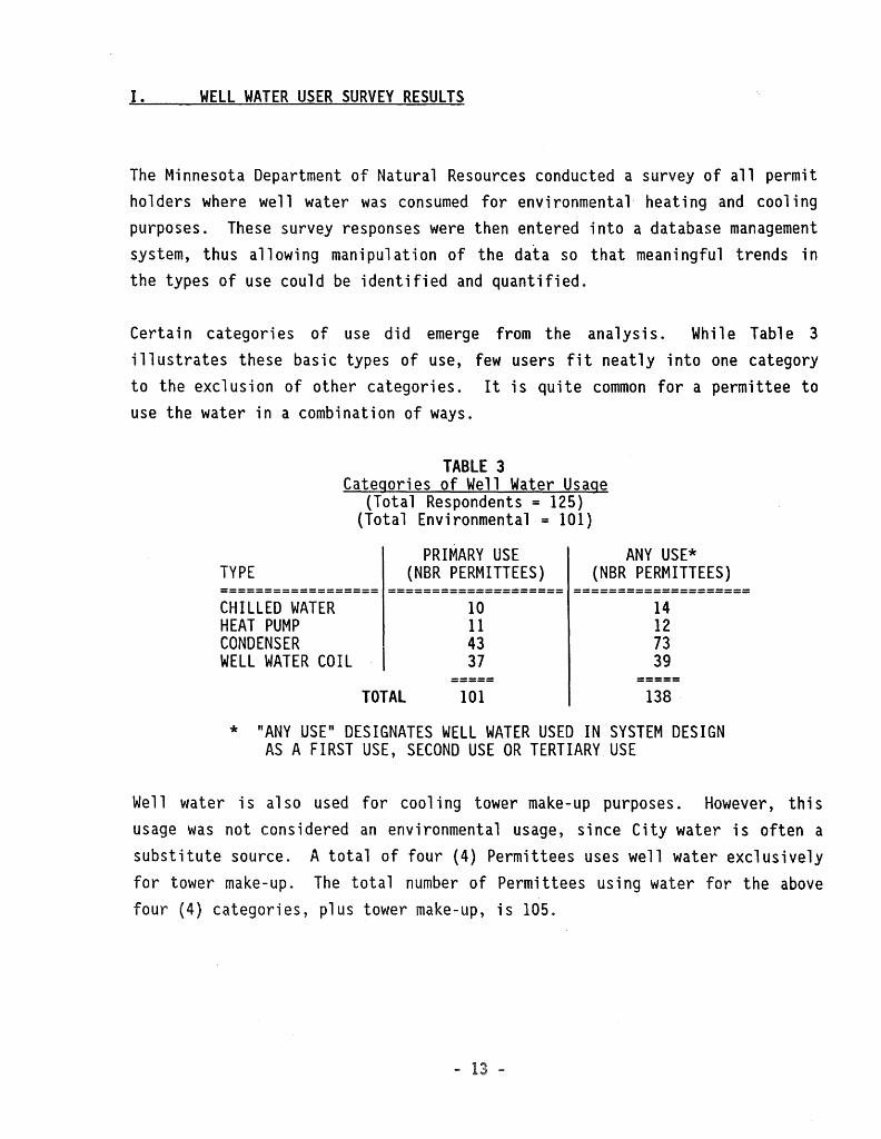
The Minnesota Department of Natural Resources conducted a survey of all permit holders where well water was consumed for environmental heating and cooling purposes. These survey responses were then entered into a database management system, thus allowing manipulation of the data so that meaningful trends in the types of use could be identified and quantified.
Certain categories of use did emerge from the ana 1 ys is. Wh i1 e Tab 1 e 3 illustrates these basic types of use, few users fit neatly into one category to the exclusion of other categories. It is quite common for a permittee to use the water in a combination of ways.
TYPE
TABLE 3 Categories of Well Water Usage
(Total Respondents = 125) (Total Environmental = 101)
PRIMARY USE (NBR PERMITTEES)
ANY USE* (NBR PERMITTEES)
================== ==================== ==================== CHILLED WATER HEAT PUMP CONDENSER WELL WATER COIL
10 11 43 37
14 12 73 39
TOTAL 101 138
* "ANY USE" DESIGNATES WELL WATER USED IN SYSTEM DESIGN AS A FIRST USE, SECOND USE OR TERTIARY USE
Well water is also used for cooling tower make-up purposes. However, this usage was not considered an environmental usage, since City water is often a substitute source. A total of four (4) Permittees uses well water exclusively for tower make-up. The total number of Permittees using water for the above four (4) categories, plus tower make-up, is 105.

Basic Categories of "Once-Through• Well Water Usage
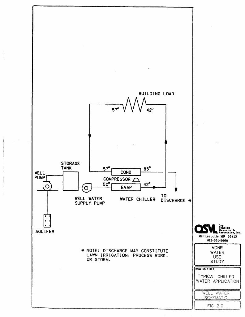
Chilled Water Chilled water applications typically route the well water through the evaporator side of a water chiller when it is first drawn from the well. The temperature of well water is usually between 50 and 53 degrees Fahrenheit year-round.
This provides an opportunity to reduce the requi cooling capaci or "tonnage" on the machine (where 1 ton s 12, BTU/hr) since entering the chiller would otherwise be approxi y to
water degrees
Fahrenheit. In other words, the entering water temperature evaporator (or "chiller") vessel is lower, thereby, reduci required chiller capacity. The well water provides a portion the cooling capaci directly. The well water is chilled to approximately ~egrees Fahrenheit is then circul to chilled water coils and other termi uni in bui di ich take advantage of its i ng in is manner is idi' a
medium of heat transfer by, first, givi in evaporator and, then, by absorbing termi 1 ea vi the terminal units, this water is still relatively cold. is reason, it
is often routed through the condenser side of the chiller, it acts as a "heat sink", and picks up heat to be rejected to an exterior heat sink. In the case of "once-through" cooling systems, this sink is usually in t~e form of a pond, stream, river, or storm sewer. This water may also be used to irrigate lawns. Figure 2.0 illustrates this design application.
- 14 -
I I
I I
I I
AQUIFER
STORAGE TANK
BUILDING LOAD
57° 42°
85° 57°--------..... COND .,___,___ l
COMPRESSOR~ 50° 42°
1-------~ EVAP ....._~......,___.
WELL WATER SUPPLY PUMP
TO WATER CHILLER DISCHARGE *
* NOTE: DISCHARGE MAY CONSTITUTE LAWN IRRIGATION, PROCESS WORK, OR STORM.
~~{el en Mayeron • AHooiat.ee, lno.
Minneapoli•. ll1' 55•13 612-331-8660
MDNR WATER
USE STUDY
DMWINO TITLE
TYPICAL CHILLED WATER
2.

Heat Pump Source/Sink Heat pumps use we 11 water in a method similar to a water chi 11 er. However, these devices are often designed to be "reversible", wherein, they act to produce a cooling effect in one mode and a heating effect when their condenser and evaporator are reversed. Figures 2.IA and 2.IB illustrate the reversible nature of most heat pumps. Depicted in Figures 2.IA and 2.IB is a specific type of heat pump called a "water source" heat pump. During the cooling mode, the well water acts as a "sink" where heat from the space, plus heat from the compressor, is picked up by the water and rejected. In the heating mode, the well water acts as a "heat source" for the heat pump. These units typically have capacities of less than 20 tons each and usually contain their own compressors. This method is referred to as "decentralized" s i nee ind i vi dual units may operate independently of each other, imparting heat or drawing heat from the source water as the need dictates.
- 16 -

I I
I I
I I
( S SI )
llilBIV<l!'f"OD. If Aslio,oilat.•11111, Inc.
:Minnenpoli1, MN 55413 612-331-6660
MDNR WATER
USE STUDY
rnu::
TYPICAL HEAT PUMP APPLICATION
( WELL WATER l SCHEMATIC

WATER SOURCE HEAT PUMPS
5cf
L 0 PUMP
i I
I I
I I
AQUIFER
COND
EVAP
/ / WARM AIR TO SPACE
/
EVAP
TO DISCHARGE *
*NOTE: DISCHARGE MAY CONSTITUTE LAWN IRRIGATION. PROCESS OR STORM ..
HE TING ODE (WELL ATER USED AS SOURCE)
Orr Schele:n :Ye.ye:ro:n fl Aesooi111te&11, !no.
Minneapoli1111, MN 55413 812-331-8660
MDNR WATER
USE STUDY
TYPICAL HEAT PUMP APPLICATION
[ WELL WATER J SCHEMATIC
( FIG 2.18 ) '----------........................ --................................................... ___________ ............, ____ ......,,~ ................................................. ---.

Condenser Water
The most common form of usage for well water is in a "condenser" application. Here, well is used to pick up heat from refrigerant, thereby acting as a "sin es the ides a means rejecting it.
Under a is
ies
ow umes are Fi . 2 i 11 is ion .

WATER CHILLER. PACKAGED COOLING UNIT. COMPUTER ROOM UNIT. OR CONDENSING UNIT. WATER CHILLER SHOWN.
WELL WATER STORAGE
WELL TANK PUMP
I I
I I
I I
WELL WATER SUPPLY PUMP
50° CONO 80°
~ COMPRESSOR 54° ----- 44° ,--1 EVAP l------1
80°
I I
6 CHILLED t ~WATER
1 PUMP CH ILLED1 I WATER I
t_ __ /\N-_'-_o~~ -_J
BUILDING LOAD
TO DISCHARGE *
AQUIFER
*NOTE: DISCHARGE MAY CONSTITUTE LAWN IRRIGATION. PROCESS WORK. OR STORM.
QS\l~t.1.11 Ma7eron Ir Aasociat.e•, me.
Minneapolis. MN 55413 612-331-8660
MDNR WATER
USE STUDY
TYPICAL CONDENSER WATER APPLICATION
[ WELL WATER J SCHEMATIC
( FIG 2.2 ) '----------........... -------------------------------'~------------

Well Water Coils The simplest way to utilize well water in environmental cooling is to circulate it directly through air-conditioning water coils. The water is cold enough to provide cooling to the space without being mechanically-cooled to a lower temperature. Environments which require a considerable amount of dehumidification may not be satisfied by 50 or 55 degrees Fahrenheit water. However, when that is the case, ground water is often used to pre-cool incoming air prior to dehumidification by refrigeration coils. The pre-cooling reduces the load on the conventional refrigerant system. Electrical costs in operating conventionally-sized chiller DX systems are reduced. The cooling effect of the ground water is obtained for the mere cost of the pumpage and water treatment. Figure 2.3 illustrates a simple version of direct-cooling with well water.
- 21 -

WELL PUMP O
I a
I I
I I
50°
AQUIFER
COLD WATER COILS
60°
TO DISCHARGE •
*NOTE: DISCHARGE MAY CONSTITUTE LAWN IRRIGATION. PROCESS WORK. OR STORM.
I I
g~hehtD Mayeron tr AHooiat.ee. Inc.
Minneapolis, MN 55413 612-331-8660
MDNR WATER
USE STUDY
DRAW r NO TI TLE
TYPICAL WELL WATER COIL APPLICATION
WELL WATER S~l:IEM8IIC
FIG 2.3
) )

Discussion
As stated previously, well water systems may utilize more than one of the
above categories in their design. It is important to note that, while the
categories described above assist in the understanding of the ways that ground
water may be used in environmental coo 1 i ng or heating, they are by no means
all-encompassing. A comprehensive analysis of the full spectrum of well water
designs is not within the scope or ti me frame of this Study. We 11 water
systems and their tendencies to overlap and defy neat categorization can be
viewed in the following manipulations of the database:
- 23 -

L~1:cu:1
MINNESOTA DEPT NATURAL RESOURCES CONSUMPTIVE WATER us~ STUDY ORR-SCHELEN-MAYERON & ASSOC
CHILLER EVAP
PERMIT NAME AUTH AUTH FIRST USE 2 USE 3 USE 4 NBR A/C REPORTED NBR MSY GP!'! USE USES HSY
74-5231 GENERAL MILLS 650.0 3700 CW COIL CHILLER COND 3 581. ( 60-0131 METRO AI~PORTS 500.0 1850 CHILLER COND PROCESS 2 382. (
COl'IMI SS ION 87-6169 BCED MINNESOTA INC. 420.0 833 CHILLER HEAT PUMP CDND. 3 308.E
- CONWED TOWER 64-0643 THS NORTHSTAR ASSOC. 350.0 0 CHILLER COND. 'j 295.; i.
78-6254 BCED DEVELOPMENT ~ 325.0 2430 CHILLER COND 2 PF:OPERTI ES, INC.
85-6295 MCC DEVELOPMENT CO., 250.0 2500 HE1H PUMP CHILLER COl'JD INC. ORDWAY MUSIC THEATER 0
'0 INC.
0 89. CHILLER
PUBLICATIONS THE LEXINGTON 65.0 500 COIL CHILLER COND COMPANY rlETF.'O SQUARE 60.0 10DO CHILLER cmm, PARTNERSHIP
0 800

Lui.·-uo'-1
MINNESOTA DEPT NATURAL RESOURCES CONSUMPTIVE WATER USE STUDY ORR-SCHELEN-MAYERDN ~ ASSOC
HEAT PUMP APPLICATIONS
PERMIT NAME AUTH AUTH FIRST USE 2 USE 3 USE 4 NBR A/C REPDF:TED NBR HSY GPM USE USES NSY
82-6002 ST. PAUL PORT 1386.0 2400 HEAT PUMP 1431. 8 AUTHORITY - ENERGY PARK
87-6169 BCED MINNESOTA INC. 420.0 833 CHILLER HEAT PUMP COND. 3 308.S - CONWED TOWER
65-1349 IND. SCHOOL DIST. 260.0 500 HEAT PUMP 33.0 861
85-6295 HCC DEVELOP~ENT CO., 250.0 2500 HEAT PUMP CHILLER COND j 0.0 INC.
80-6214 H.B. FULLER COMPANY 185.0 1500 HEAT PUMP CW COIL 2 0.0 B-O 0201 Y g~ M~I At ES ue. 3 3139 llEAt RE INJECT 1- 39.0 66-1196 TOWLE REAL ESTATE - 33.0 1000 HEAT PUMP CDND 2 0.0
NDRWEST CR, ST P. 86-6178 iiliLLiiH1 ULRICH 11. 0 100 HEAT PUMP 0.0 86-1090 PA~UDA INC. 9.0 35 HEAT PUMP 16. (l 81-3229 iilIDSETH SMITH 6.0 16 HEAT PUMP 1.3
tlDL TINS BB-1123 DAVID LUNDEEN 6.0 0 HEAT PUMP 1 ... cc
.:> • .J
86-2114 JACK WILLIAMS 4.0 20 HEAT PUMP 1 5.0 90-3026 ACROMETAL COMPANIES, 0.0 0 HEAT PUMP 1 0.0
INC. Hf Total *H
2680.0 9204 18 1838.4

MINNESOTA DEPT NATURAL RESOURCES CONSUMPTIVE WATER USE STUDY ORR-SCHELEN-MAYERON & ASSOC
CONDENSER APPLICATtONS
PERMIT NAME AUTH AUTH FIRST USE 2 USE 3 USE 4 NBR A/C REPORTED NBR MGY SPM USE USES MSV
74-5231 GENERAL MILLS 650.0 3700 CW C01L CHILLER COND 3 581.0 60-0131 METRO AIRPORTS 500.0 1850 CHILLER COND PROCESS 2 382.0
COMMISSION 87-6169 BCED MINNESOTA INC. 420.0 833 CHILLER HEAT PUMP COND. 3 308.8 '
- CDNWED TOWER 63-0519 Si. PAUL - RAMSEY 385.0 3200 COND. 169.7
HOSPITAL 85-6129 HONEYWELL INC. 380.0 2300 COND. 157.0 60-0466 UNITED HOSPITALS 360.0 2625 COND, 162.8 64-0643 THS NORTHSTAR ASSOC. 350.(l 0 CHILLER CDND. 2 295.7 78-6254 BCED DEVELOPMENT & 325.0 2430 CHILLER COND 2 628.0 PROPERTIES, INC. 85-6227 DAYTON'S - 300.0 4000 COND, 255.0
MINNEAPOLIS 85-6010 METHODIST HOSPITAL 300.0 1650 CW COIL COND 'i 222.0 ... 66-0906 McCOURTNEY PLASTICS 290.0 550 COND, PROCESS 219.0 85-6267 NORWEST BANK 250.0 3000 CDND. 0.0 BUILDING CO. 69-0707 FEDERAL RESERVE BANK 250.0 212s co~m. 485.6 85-6295 MCl_D~VELOFNENT CO. , 250.0 2500 HEAT PUMP CHILLER COND 0.0
INC. 85-6140 HFS PEOPERTIES 220.0 1000 CW COIL COND 10. 60-0196 HEIT~AN NN 200.0 3000 cmrn.
MANAGEMENT 88-6011 VETERANS 195.0 822 CW COll
ADM IN I STRAT IO~ 87-6288 MOUNT SIANI MEDICAL 195.0 650 COND
CENTER 63-0066 ABBOTT NORTHWESTERN 175.0 2900 COND.
HOSP IT AL 65-0519 RADISSON - ST. PAUL 160.0 700 CW COIL CDND 6H 17 WEBB PUBLISHING CO. 151.0 850 CDND. PROCESS 191. 86-6315 U OF MN - 120.0 0 COND. 10.l: CIVIL/MINERAL ENGRG
BLDG 86-6129 ORDWAY MUSIC THEATER 110. i) 750 CHILLER COND '") 108. I.' ... 65-1327 ECO LABS 102.0 1500 CW COIL COND 2 16, I,
75-6268 UNITED PROPERTIES 101. 5 0 CW COIL COND 2 142. '; 72-0569 APPLETREE 101. 0 10 CHILLER COND 2 127. ,,
ENTERPRISES, INC. 85-6037 MINNEAPOLIS 6RAIN 100.0 650 cmm. 45, 1,
EXCHANGE 60-0061 THORPE BROTHEF:S. 100.0 1500 CW COIL COND '1 5.' ..;_
INC. 62-0727 DAYTIJN'S - ST. PAUL 95.4 1000 CW COIL COND 2 0. '-85-6073 FAIRVIEW SOUTHDALE 90.0 3000 COND, 229. 1,
HOSPIT~L

MINNESOTA DEPT NATURAL RESOURCES CONSUHPTIVE WATER USE STUDY ORR-SCHELEN-HAYERON & ASSOC
CONDENSER APPLICATIONS
PERt'llT NAME AUTH AUTH FIRST USE 2 USE 3 USE 4 NBR A/C REPOI NBR MSY GPM USE USES
62-0138 N. W. BELL - 74. 0 750 COND. MINNEAPOLIS
87-6193 MINNEAPOLIS ENERGY 73.0 1200 CDNO. CENTER INC.
75-6188 MEDICAL ARTS 71.2 1000 COND. BUILDING
59-0896 NORHANDALE 70.0 750 CW COIL cmm ') ~
PROPERTIES, INC. 85-6011 THE SAINT PAUL HOTEL 70.0 500 CHILLER COND 2 59-0736 ST. JOSEPH'S 69.0 950 CDND. 1
HOSPITAL 84-6069 NORTHWEST 65.0 1200 CONO. CHILLER 2 ')'
4,
PUBLICATIONS 75-6161 THE LEXINGTON 65.0
COMPANY 500 CW COIL CHILLER COND 3
80-6275 PRUDENTIAL INSURANCE 60.0 1500 CW COIL COND 2 85-6128 METRO SQUARE 60.0 1000 CHILLER COND. 2
PARTNERSHIP 59-0420 ST. PAUL CIVIC 60.0 750 CONO.
CENTER 85-6081 MINNEAPOLIS ATHLETIC 60.0 600 COND.
CLUB 58-0243 ROCHESTER AIRPORT 52.0 200 COND.
co. 85-6055 PACiFIC GAMBLE 50.0 200 COND.
ROBINSON CO. 61-0320 MARQUETTE BANK - 45. (I 750 CDND.
MINNEAPOLIS 60-0229 DESF:EE OF HONOR 40.0 500 CDND.
PROTECTlVE ASSN. 85-6224 MINNESOTA VETERANS 40.0
HOME-HASTINGS BOO CHILLER COND PROCESS 2
65-1258 FARM CREDIT BANKS OF 36.0 500 Cl4 COIL COND 2 ST. PAUL
63-1113 NW NATIONAL LIFE 35.0 650 CW COIL COND 2 INSURANCE CO. 66-1196 TOWLE REAL ESTATE - 3:.;.o 1000 HEAT PUHP COND 2
NORWEST CR, ST P. 59-0771 C.P.S. DEPARTMENT 30.0 350 CW COIL COND 2 STORES INC. 85-6202 CARSO~ PIRIE SCOTT - 30.0 1000 CDND.
SOUTHDALE BS-6226 CITY OF MINNEAPOLIS 30.0 365 cmm.
HEALTH CENTER 76-6201 RAMSEY COUNTY 30.0 360 CHILLER corm PROCESS 2 SHERIFF'S DEPARTMENT 77-6345 ROSE~400D 5TH ~ 28.(1 300 cmrn.
MARQUETTE LIMITED PART

12/~7:89
MINNESOTA DEPT NATURAL RESOURCES CONSUMPTIVE WATER USE STUDY ORR-SCHELEN-MAYERON ~ ASSOC
CONDENSER APPLICATIONS
PERMIT NAME AUTH AUTH FIRST USE 2 USE 3 USE 4 NBR A/C REPORTED NBR MSY GPM USE USES rm
85-6090 THE 614 COMPANY 20.0 450 COND. 11. 0 85-6052 WCCO RADIO BUILDING 20.0 400 COND. b.: 59-0760 MIDLAND HILLS 20.0 0 COND. 223.4. COUNTRY CLUB 79-6148 IND. SCHOOL DIST. 12.0 0 CW COIL COND. LAWN 2 13.0
272 85-6051 RAMSEY COUNTY 10.0 750 cmm. 6.9 COURTHOUSE 75-6232 YWCA 10.0 200 COND. 6.5 85-6172 ORPHEUM THEATRE 10.0 200 COND. 5.0 62-0599 THE ARCHDIOCESE 6.0 100 COND. 2.5 78-6257 TRACH PROPERTIES, 5.0 225 COND. 3.0
INC. 67-0032 JESUIT RETREAT HOUSE 4.3 60 COND. 1 1.3 82-6127 TOWLE REAL ESTATE 4.0 525 CW COIL COND 2 3.9
-METRO BANK BLDG 75-6259 EQUITABLE LIFE 3.B 145 COND. 8 r1
ASSURANCE 64-0014 KENNEDY HIGH SCHOOL 3.6 170 COND. 1 2.0 84-6233 NORWEST BANK - 3.0 50 CW COIL COND 2 1. 6
CAMDEN 85-6048 LAKEWOOD CEMETARY 1. 0 200 COND. 0.6
ASSN. 60-0379 LYNDAHL MOTOR 1. 0 20 COND. 0.4
COMPANY 75-6231 HONEYWELL AVIONICS 268.0 694 cmm. QJ (..OIL 0 '1 DC.~ n DOHC..>TfC,
2. 367.9 66-1194 ICI COMPOSITES, INC 0.0 0 COND. PROCESS 1 149.8
fH Total Hf
8903.B 70959 ..H-r- 7557.5

MINNESOTA DEPT NATURAL RESOURCES CONSUMPTIVE WATER USE STUDY ORR-SCHELEN-MAYERON ~ ASSOC COLD WATER COIL APPLICATIONS
PERMIT NAME AUTH AUTH FIRST USE 2 USE 3 USE 4 NBR AiC REPORTED NBR MSY GPM USE USES 116Y
74-5231 GENERAL MILLS 650.0 3700 CW COIL CHILLER CDND 3 581. 0 85-6010 METHODIST HOSPITAL 300.0 1650 CW COIL COND 2 222.0 85-6140 HFS PROPERTIES 220.0 1000 CW COIL COND 2 110.5 88-6011 VETERANS 195.0 822 CW COIL COND 2 119. 0
ADMINISTRATION 80-6214 H.B. FULLER COMPANY 185.0 1500 HEAT PUMP CW COIL 2 0.0 65-0519 RADISSON - ST. PAUL 160.0 700 CW COIL COND 2 133.3 85-6115 U~HSYS 110.0 1000 CW COIL 73.5 85-6061 NORTHWESTERN BELL 110. 0 0 CW COIL 50.6 65-1327 ECO LABS 102.0 1500 CW COIL COND 2 16.0 75-6268 UNITED PROPERTIES 101. s 0 CW COIL COND 2 142.0 60-0061 THORPE BROTHERS~ 100.0 1500 CW COIL COND 2 5.0
INC. 62-0727 DAYTON'S - ST. PAUL 95.4 1000 CW COIL COND 2 0.0 89-6129 IDS FINANCIAL 89.0 250 CW COIL TOWER ., 0.0 i..
SERVICES 59-0896 NORMAND ALE 70.0 750 CW COIL COND 2 o.o
PROPERTIES, INC. 85-6083 HHJNESASCO 70.0 600 CW COIL 102.0 61-0378 PRODUCT DESIGN AND 70.0 200 CW COIL 63.(
ENSINEERINC. INC. 75-6161 THE LEX!NSTON 65.0 500 CW COIL CHILLER COND 3 so.o
COMPANY 61-0294 JOHN DEERE COMPANY 61. 2 600 CW COIL 43.0
OF MINNEAPOLIS 80-6275 PRUDENTIAL INSURANCE 60.0 1500 CW COIL COND 2 59.0 75-6206 U OF NN - OFFICE 37.8 500 CW COIL 62.6 65-1258 FARM CREDIT BANKS OF 36.0 500 CW COIL CDND 2 o.o
ST. PAUL 63-1113 NW NATIONAL LIFE 35.0 650 CW COIL COND 2 83.0
INSURANCE CO. 85-6097 Hl6HLAND CENTER, 30.0 350 CW COIL 924.0
INC. 59-0771 C.P.S. DEPARTMENT 30.(1 350 CW COIL COND 2 0.0
STORES INC. 85-6116 UNISYS COF:P. 30.0 520 CW COIL 15.2 76-6231 HAZELDEN PIONEER 20.0 200 CW COIL 18.C
HOUSE 86-6003 MINNEAPOLIS PUBLIC 20.0 0 CW COIL 32.S
LIBRARY 65-0563 BROM MACHINE & 12.0 250 CW COIL 6.~
FOUNDRY 79-6148 IND. SCHOOL DIST. 12.0 0 CW COIL COND. LAWN 2 13. (
272 85-6210 BERWALD INVESTMENT 10. (I 200 CW COILS 17.: 60-0920 SARSENT INDUSTRIES 9.2 310 Cl~ COlL 9.t 61-0538 ECO LABS 8.7 500 CW COIL TOWER 2 4.5

l:12~us9
HINNESDTA DEPT NATURAL RESOURCES CONSUMPTIVE WATER USE STUDY DRR-SCHELEN-MAYERON & ~ssoc COLD WATER COIL APPLICATIONS
PERMIT NAME AUTH AUTH FIRST USE 2 USE 3 USE 4 NBR A/C REPORTED NBR HSY SPH USE USES HSY
85-6361 LUNDS. INC. 7.0 60 CW COIL 0.0 87-2145 NORTHERN ITASCA 4.2 65 CW COIL 3.4
HOSPITAL " 82-6127 TOWLE REAL ESTATE 4.0 525 CW COIL COND 2 3.9
-METRO BANK BLDG 84-6233 NORWEST BANK - 3.0 50 CW COIL COND 2 1. 6 ~'
CAMDEN 75-6282 CHURCH OF ST. ANNE 1.2 150 CW COIL 0.0 60-0603 GENERAL HILLS 0.0 0 CW COILS PROCESS FIRE LAWN 433.6
Hi Total n1
3124.2 23952 3399.0

:""!
12/29/89 MINNESOTA DEPT NATURAL RESOURCES
CONSUMPTIVE WATER USE STUDY ORR-SCHELEN-11AYERON & ASSOC
f'JON- ft-JV1t<..o,._,,..,._ VT4L-
PERMIT NAl1E AUTH AUTH FIRST USE 2 USE 3 USE 4 NBR A/C REPORTED NBA 11GY Gf'tt USE USES HGV
7r,,...b269 EQUITABLE -SEE 0.0 0 () 0 0.0 75-6259 . tDUPLlCATEl
75-6172 WEST PUBLISHING 34.0 910 DOHESTIC 0 13.7 85-6171 SPECIALTY 20.0 SO MACHINERY 0 5.0
ffANUFACTURING COl1PANY
62-0615 WHIT AKER CORP 3.0 200 NONE 0 0.1
66-1060 NORTH STAR STEEL 426.5 800 PROCESS 0 10.5
60-0010 ST. 11ARY'S HOSP 10.0 450 DOMESTIC 0 0.1
73-1413 CONTROL DATA 30.0 300 PROCESS 0 41. 0
75-6252 VANCE PIONEER 14.0 450 NONE 0 0.0
76-6340 DISTRICT HEATING CO 120.0 700 NONE 0 o.o 85-6033 ST. PAUL BURLINGTON 20.0 600 DOMESTIC 0 0.0
LTD PARTNERSHIP tH Total Ht
677. 5 4460 0 70.4

SURVEY RESULTS
Permittees which utilize ground water for condenser applications outweigh all other uses. 73 out of 101 environmental users utilized well water on the condenser side of compressorized equipment. Ground water was used directly in cooling coils in 39 out of 101 environmental users.
In all cases where well water was used on the evaporator side of a chiller, it was also used on the condenser side. Figure 1.0 is, therefore, typical of all chilled water {evaporator water) applicatiQns, except for minor variations. Well water was used an average of 2.3 times in those cases where it was used on the evaporator side. In other words, in those designs where well water was used on the evaporator side, it was always used on the condenser side, accounting for "two uses". In some cases, it was used a third time {such as for pre-cooling air streams).
Heat pump applications tended to use the water only once. This occurred in 8 out of 12 cases.
Well water was used more than once in 33 instances.
It was hoped that numerical data from the survey relating to total capacity, hours of operation and efficiency {EER or COP) could be used to ascertain total tonnage of equipment, tonnage per category, efficiencies, etc. This was not possible due to the nature of the responses. Many surveys did not list the information and many respondents clearly did not have the ability to fill out the questions as intended. Data re 1 at i ng to tot a 1 Mi 11 ion Gallons per Year {MGY) was also deceiving. For example, General Mills has four (4) wells and reported 581 MGY in 1987. However, an in-depth ana 1 ys is revea 1 ed that Wells #3 and #4 were for environmental usage, while Wells #1 and #2 were for fire protection and domestic use. Honeywell Avionics uses ground water for environmental, process and domestic purposes, in that order. Sixteen (16) man hours of calculations were required to ascertain the portion of their total MGY which was environmental.
- 32 -

CANDIDATES FOR IN-DEPTH ANALYSIS
In order to discuss, with authority, the usage of ground water for environmental benefits and its associated costs, four (4) systems operating in Minnesota were selected for closer analysis. Representatives of each of the four (4) categories above were sought. Database manipulation produced a listing of all permittees based on stated use~ An Advisory Committee to the MDNR, meanwhile, provided input to OSM regarding direction and content of the study. Volunteers for in-depth analysis were sought at these monthly Advisory Group meetings. Based on OSM's experience in design, a facility which could easily convert to district cooling was also desired. St. Paul does not have a district cooling facility at the present time, although it does have district heating. A downtown Minneapolis facility was selected which could capitalize on the availability of purchased chilled water from the Minneapolis district cooling facility.
The candidates for an in-depth study and,their categories of usage were:
TABLE 4 Candidates for In-Depth Analysis
==============================================================================
FACILITY WELL WATER USAGE DISCHARGE ================== =================================== =======================
General Mills Chiller Evaporator, Water Coils, Recreation Pond and Condenser
Gaviidae Heat Pumps, Condenser, and To Storm Chilled Water Pre-Cool
Honeywell Condenser and Water Coils Process, Lawn and Avionics Storm
Methodist Condenser and Water Coils Recirculated first, Hospital to Storm
==============================================================================
- 33 -

II. ANALYSIS OF SELECTED NONCE-THROUGH~ SYSTEMS
GENERAL MILLS
General Mills Headquarters is a 608,900 square foot facility using we 11 water l cold water coils (Figure 3.0 il design). ls #1 and #2 are pri ly used for fire protection domestic uses, while Wells #3 and #4 are used for environmental cooling most exclusively. Supplemental pumps 11 A/C-l" and 11 A/C-2" head sure sensed in the main l supply
line, providi system when requi #3 ume pumps.
ves l
lls has ix 6
Ei can
i 11 er
l water s i 11 er
i 11 ers #1
The condenser their a common splash
system,
ill ers # ,
ildi 's
uni spaces.
ine is .
#C9 are 360
Fahrenhei ( KW/ton.
condenser vessels six (as shown in Figure 4. ) .
serve.
#3 are
itions,
a
eaving),
i 11 ers
is sp l
tank other
from rainwater downspouts as well as from the water systems. Two-way modulating valves on the inlet sides the
condenser vessels compensate for fluctuations in inlet water temperatures.
- 34 -
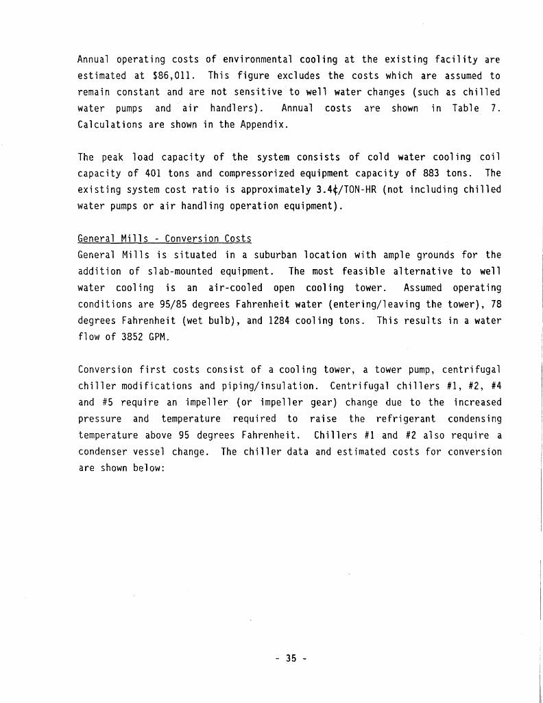
Annual operating costs of environmental cooling at the existing facility are estimated at $86,0ll. This figure excludes the costs which are assumed to remain constant and are not sensitive to well water changes (such as chilled water pumps and air handlers). Annual costs are shown in Table 7. Calculations are shown in the Appendix.
The peak load capacity of the system consists of cold water cooling coil capacity of 401 tons and compressorized equipment capacity of 883 tons. The existing system cost ratio is approximately 3.4¢/TON-HR (not including chilled water pumps or air handling operation equipment).
General Mills - Conversion Costs Genera 1 Mills is situated in a suburban 1 ocat ion with amp 1 e grounds for the addition of slab-mounted equipment. The most feasible alternative to well water cooling is an air-cooled open cooling tower. Assumed operating conditions are 95/85 degrees Fahrenheit water (entering/leaving the tower), 78 degrees Fahrenheit (wet bulb), and 1284 cooling tons. This results in a water flow of 3852 GPM.
Conversion first costs consist of a cooling tower, a tower pump, centrifugal chiller modifications and piping/insulation. Centrifugal chillers #1, #2, #4 and # 5 require an i mpe 11 er (or i mpe 11 er gear) change due to the increased pressure and temperature required to temperature above 95 degrees Fahrenheit.
raise the refrigerant condensing Chillers #1 and #2 also require a
condenser vessel change. The chiller data and estimated costs for conversion are shown below:
- 35 -
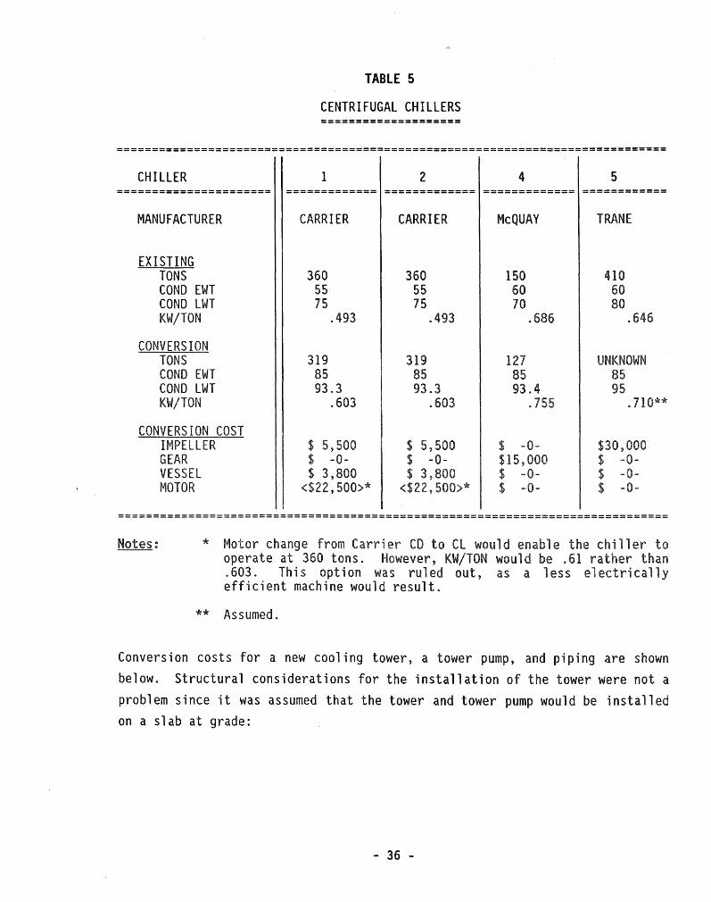
TABLE 5
CENTRIFUGAL CHILLERS ====================
==============================================================================
CHILLER I 2 4 5 ====================== ============= ============= ============= ============
MANUFACTURER CARRIER CARRIER McQUAY TRANE
EXISTING TONS 360 360 150 410 COND EWT 55 55 60 60 COND LWT 75 75 70 KW/TON .493 .493 .686 .646
CONVERSION TONS 319 319 1 UNKNOWN COND EWT 85 85 85 COND LWT 93.3 93.3 93.4 KW/TON .603 .603 . 710**
CONVERSION COST IMPELLER $ 5,500 $ 5, $ -0-GEAR $ -0- $ -0- $15, VESSEL $ 3,800 $ 3,800 $ -0-MOTOR <$ ,500>* $ -0-
==============================================================================
* Motor change from er to CL would e the iller operate at 360 tons. However, KW/TON would be . than .603. This option was ruled out, as a less electrically efficient machine would result.
** Assumed.
Conversion costs for a new cooling tower, a tower pump, and piping are shown below. Structural considerations for the installation of the tower were not a problem since it was assumed that the tower and tower pump would be installed on a slab at grade:
- 36 -

==============================================================================
================= ================= ================= =======================
CAPACITY
CONDITIONS
COST
1284 TONS
3854 GPM
85/95
$68°, 116
125 HP
100' HD
1750 RPM
$ 9,,010 $347,362
==============================================================================
The elimination of well water from the system would mandate the conversion of existing well water cooling coils to chilled water. Piping costs were estimated and included in the conversion first costs. Cost estimates from General Mills for this conversion include the replacement of three (3) chillers for a total cost of $1,500,000. The cost breakdown is $715,942 each (for A/C equipment and installation) and $68,116 (for a cooling tower).
General Mills - Operating Costs (Cooling Tower Svstem) Annual operating costs for a cooling-tower-based system are $100,862 (as shown in Table 18). The conversion to a cooling tower operating at 95/85 degrees Fahrenheit causes the input KW of the centrifugal chillers to increase dramat i ca 11 y (as shown in the centri fuga 1 chi 11 er table above). The tot a 1 operating cost ratio for the new system is estimated to be 4.3¢/TON-HR.
- 37 -

The operating cost comparisons for General Mills are:
TABLE 7
==============================================================================
ANNUAL EXISTING (WELL WATER) CONVERSION (COOLING TOWER) TON-HOURS
(EST.) ============ =============================== ===============================
2,529,600 2,355,610*
ANNUAL OPERATING COST
$/TON-HR ANNUAL OPERATING $/TON-HR COST
------------------ ------------ ------------------ ------------
$ 86' 011 .0340 $100,862 .0428
==============================================================================
* CONVERSION TON-HOURS
General Mills - Life Cycle Cost Comparison A life cycle cost analysis of the existing system is shown in Table 21. (Note that the age of the existing equipment is not taken into account and replacement costs of existing machinery are not included). The life cycle cost is based on a 20-year 1 ife, 8% discount rate, no sa 1 vage, 5% fuel escalation, and 4% water treatment cost inflation.
Life eye 1 e costs for a system utilizing a. coo 1 i ng tower to obtain coo 1 i ng water are shown in Table 22. The first costs for converting to an air-cooled coo 1 i ng tower appear in the tabulation. The total cost is a "present worth 11
cost (in 1989 dollars) of a system operating for 20 years. The comparison is as follows:
LIFE CYCLE COST
BASE SYSTEM (WELL WATER) ................... $1,276,178 CONVERSION (COOLING TOWER) ................. $2,998,354
- 38 -

C7
ca C10
C12
C13
WEST WING AHU'S
A/C PU..,
00t.4ESTIC & FIRE RESERVOIR
NC
WELLS
C4 C2 CHILLED WATER
EVAP EAST
N.O.
N.C.
CHILLER #4 150 TON t----'-~-E:-1!"1rr~E
MAIN <NORTH>
~HOUSE
PERlt.fETER FAN COIL UNITS
WATER TREATt.fENT
SPLASH TANKS
CONDENSER WELL WATER ANO RAIN WATER
*
C6
PERlt.fETER FCU'S P-2 P-8A
--· ----J'"()\-, ABSORBER~ 1 160 TONS P-12 I
~ I I I I I I I I I I
H - EVAP I ' ....... I I I I I
I
' CHILLER #5
: 410 TONS I I I I I I
BELL TOWER PENTHOUSE AHU'S C25. c2s.c21.c2a
L------------------J CHILLED WATER LOOP
l
TO RECREATION POND r---- -@P-11
I 1 0 -----1 I -- -, l I fr0P-12 I r r-& __ ....,. __ J : L_ P-13 :
.-----·~ @--·--~ I I I
..L.-._ : ' I I I I
:~ EAST WING 1 AHU'S I
I ..,-- I I I
CH~LLEO ..... -: WATER : LOOP 1 I
I I I I
P-1'0.:'t r-0 CHILLER #3
350 TONS
TO RECREATION PONO
QS\\ tt .... ll•JOro• • .b.Ooolal.M, hoa
l.Unnoapolla, IOI 61Mlll U2·33l·IMMSO
MONR WATER
USE STUDY
-11811TU
GENERAL MILLS

GAVllDAE COMMONS
Gaviidae Commons is a 125,000 sq. ft. retail facility located in downtown Mi nneapo 1 is. It utilizes a combination of water source heat pumps, water chillers, and well water heat exchangers in its design. The well water pumped ~or Gaviidae is also shared with the neighboring Saks Fifth Avenue Building. Of the 1600 GPM flow rate at the well pump, 1000 GPM is dedicated to Gaviidae. This study disregards the Saks portion of the well water (Figure 3.1
illustrates the design), since no information was received from the design engineer.
This facility was chosen for in-depth analysis due to its employment of water source heat pumps and its ability to convert to a purchased chilled water agreement. In fact, the downtown district cooling facility has water pipes that are "stubbed" to supply chilled water to Gaviidae.
There are 105 water source heat pumps currently installed in Gaviidae Commons. They primarily serve the individual tenants in the building. This provides a flexibility of design by enabling the Owner to add more heat pumps to serve new tenants, change sizes as user load profiles change, and provide independent control of each space. A further allowance for expansion to twice the existing capacity is in the design. A heat exchanger pro vi des the well water source/sink required by the heat pumps, which operate at an electrical efficiency of approximately 12.3 BTUH/Watt at 70/85 degrees Fahrenheit ( enteri ng/l eav i ng) source water temperature. By contrast, the energy efficiency rating at 85/95 degrees Fahrenheit (entering/leaving) source water temperature is approximately 11.3 BTUH/Watt.
The commons area is served by two (2) centrifugal chillers of 265 tons each. The centrifugal chillers operate at a design efficiency of .414 KW/Ton.
The aforementioned well water heat exchanger serves to pre-cool the chilled water as it returns from the building, prior to being chilled in the evaporator vessel of the water chiller. Approximately 128 tons of cooling are achieved from the well water in this fashion.
.. 40 -

Annual environmental cooling operating costs are estimated at $42,692. Annual costs are shown in Table 3. Calculations are shown in the Appendix.
The total peak load of the system consists of a well water heat exchanger at 128 tons, centrifugal water chillers at 500 tons, and water source heat pumps at 284 tons. The existing well water system cost ratio is approximately 6.2¢/TON-HR.
Gaviidae Commons - Conversion Costs The downtown location of the facility lends itself well to district coo 1 i ng/heat i ng. Cooling towers would a 1 so be feas i b 1 e; however, space for the new cooling tower cou1d be a problem. Structural costs and considerations for a roof-mounted cooling tower could not be ascertained within the scope of this study.
The building already utilizes district steam heating, and the district cooling chilled water lines are stubbed to receive connections from a future chilled water system from Gaviidae. The water for the water source heat pumps would be heated from a new steam-to-water heat exchanger during the winter season. During the cooling mode, these units could either operate on source water-cooled (by purchased chilled water) or possibly on return water from the chilled water loop for the commons area.
Gaviidae Commons - Conversion Costs (Cooling Tower)· Conversion costs for a cooling tower consist of a cooling tower, a tower pump, centrifugal chiller modifications, piping, and a new reciprocating water chiller of 128 tons (to supplement the 128 tons of well water pre-cooling).
The centrigual chillers would require a gear change to operate at 85/95 degrees Fahrenheit (entering/leaving) condenser water temperatures. The centrifugal chiller data and estimated costs for conversion are shown on the following page.
- 41 -
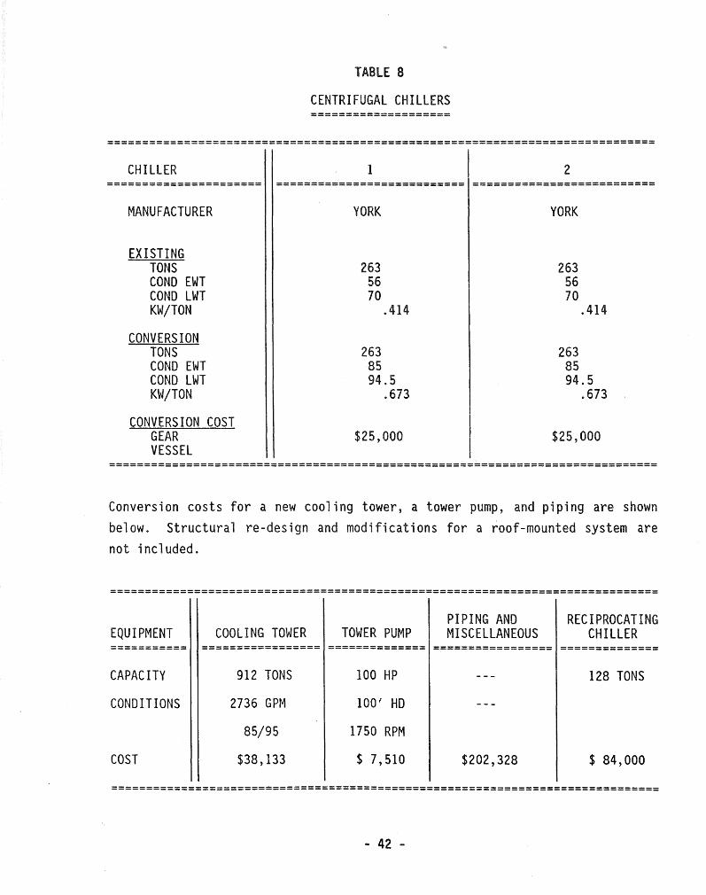
TABLE 8
CENTRIFUGAL CHILLERS ====================
==============================================================================
CHILLER l 2 ====================== =========================== ==========================
MANUFACTURER
EXISTING TONS COND EWT COND LWT KW/TON
CONVERSION TONS COND EWT COND LWT KW/TON
CONVERSION COST GEAR VESSEL
YORK
263 56 70
.414
263 85 94.5
.673
$25,000
YORK
263 56 70
.414
263 85 94.5
.673
$25,000
==============================================================================
Conversion costs for a new cooling tower, a tower pump, and piping are shown below. Structural re-design and modifications for a roof-mounted system are not included.
==============================================================================
EQUIPMENT COOLING TOWER TOWER PUMP PIPING AND MISCELLANEOUS
RECIPROCATING CHILLER
=========== ================= ============== ================= ==============
CAPACITY
CONDITIONS
COST
912 TONS
2736 GPM
85/95
$38,133
100 HP
100' HD
1750 RPM
$ 7,510
128 TONS
$202,328 $ 84,000
==============================================================================
.. 42 -

Gaviidae Commons - Conversion Costs (District Cooling) Conversion costs for district cooling consist of a new steam-to-water heat exchanger for the heat pump source loop, piping, and insulation. Piping changes depend on the method chosen to supply cooling water to the heat pump source loop during its cooling mode.
Conversion costs are estimated to be:
TABLE 9 First Costs
====================================================
SYSTEM STEAM HEAT EXCHANGER PIPING
============ ======================== =============
CAPACITY
COST
3890 LBS/HOUR
$26,700 $11, 160
====================================================
Gaviidae Commons - Operating Costs (Cooling Tower Svstem) Annual operating costs for a cooling-tower-based system are $48,030 (as shown in Table 18). The operating costs on a "$/TON-HR" basis is estimated to be 6.97¢/TON-HR.
Gaviidae Commons - Operating Costs (District Heating/Cooling) Annual operating costs for a district cooling system and a district heating-supplied heat exchanger are $106,081. Annual operating costs for purchased cooling a 1 one are $112, 948 for an estimated 400 tons and 900 Full Load Hours. The actual purchased chilled water operating cost on a "$/TON-HR" basis is estimated to be 31.4¢/TON-HR. For comparison with well water and tower systems, the cost of maintenance, labor and capitol equipment shall be excluded. The resultant comparison cost is 22. 5¢/TON-HR. While costs on a "$/TON-HR" basis are high, the building takes advantage of only purchasing the water it needs. The maintenance, labor and unscheduled service costs related to the equipment are borne by the district supplier and not by the Owner. The
- 43 -

steam costs are not total building steam costs but, rather, additional steam costs necessary to supply the heating mode heat pump source water which was
lost by the elimination of aquifer ground water.
Gaviidae Commons - Cost Comparisons The operating cost comparisons for Gaviidae Commons are:
TABLE 10
==============================================================================
EXISTING (WELL WATER)
========================== ANNUAL ANNUAL OPERATING $/TON-HR COST
--------------- ----------$ 42,692 .0619
CONVERSION (COOLING TOWER)
======================= ANNUAL ANNUAL OPERATING $/TON-HR COST
------------ ----------$ 48,030 .0697
CONVERSION (DISTRICT COOLING)
========================= ANNUAL ANNUAL OPERATING $/TON-HR* COST*
------------ ------------$ 81,000 .2250·
==============================================================================
Note: * Cooling only for comparison, labor, maintenance and capitol equipment costs excluded.
- 44 -

Gaviidae Commons - Life Cycle Cost Comparison A life cycle cost analysis of the existing system is shown in Table 21. The equipment at Gaviidae is almost new and a 20-year life is expected.
Life cycle costs for a system utilizing a cooling tower to obtain cooling water are shown in Table 22. The total cost is a "present worth" cost (in 1989 dollars) of a system operating for 20 years and includes first costs.
Life cycle costs for a district cooling/heating system are shown in Table 23 and, likewise, include first costs.
LI FE CYCLE COST
BASE SYSTEM (WELL WATER) ................... $ 628,037 CONVERSION (COOLING TOWER) . . . . . . . . . . . . . . . . . 1,044,005 CONVERSION (DISTRICT HEATING/COOLING) ...... 1,499,338

100 HP <75 HP WITHOUT SAKS>
#1 #2
WATER TREATMENT
125 HP ---1
STANDBY WELL WATER SUPPLY PUMP
TO •sAKS' BUILDING -NOT INCLUDED IN STUDY
___________ ..,. TO WATER SOURCE } HEAT PUMPS
-- 105 UNITS --@---... --FROM WATER SOURCE 284 TONS.
25 HP WATER . HEAT PUMPS SOURCE PUMP
INSTALLED.
---______ _..,.
r-@-- ~~IJ;L~ •• TER
---WELL WATER HEAT EXCHANGER 128 TONS
I I I
I I 1_1
------ 1----· -- .L c - - - -@-a- L~6~L~ WATER
SURGE TANK
TO STORM

HONEYWELL AVIONICS
Honeywell Avionics Division is a 525,000 square foot facility using well water for environmental cooling, process cooling, and domestic purposes. The env i ronmenta 1 portion utilizes approximate 1 y 85% of the tot a 1 water appropriated. There are two (2) ground water.wells and the system is designed in a parallel fashion so that either well delivers water to all water-cooled equipment. The system is diverse and has expanded as the facility has expanded. The well pumps are constant volume pumps. Two-way modulating valves at the units control the amount of water that they receive.
Due to the complexity of the system, a schedule of equipment will be used to describe the system components. Refer to Schematic Drawing 4.2, Schedule 4.2A and Schedule Notes 4.28 for a complete system description. (Note that the system is more complex than that shown in Schematic Drawing 4. 2, but the schematic depicts the salient features).
Annual operating costs of environmental cooling at the sting facility are estimated at $242,870. Annual costs are shown in Table 17. Calculations are shown in the Appendix.
The total peak cooling capacity of the system is estimated at 1507. 4 tons. The calculation is shown in Appendix A-5.
Note that the majority of env i ronmenta 1 coo 1 i ng is accommodated by two ( 2) centrifugal chillers (AC04 and ACOS) with capacities of 500 tons and 300 tons, respectively. These units operate ahead of other reciprocating water chillers (such·as AC06) which pick up peak loads, as required.
The estimated annual operating cost ratio was derived from the annual operating costs (as shown in Table 17). The portion of that annual cost which is derived from the operation of compressorized equipment is shown in Appendix A-1. The efficiencies of the equipment at 50 degrees Fahrenheit entering condenser water temperature have been taken into account in this analysis. Total hours of operation and estimated loads were provided by Honeywell. The total estimated operating cost ratio of the existing system is $.0283/TON-HR.
- 47 -

Honeywell Avionics - Conversion Costs e conversion l ionics s an air- ed
s it ions are
is in ow 1
Conversion first costs consist of a cooling tower, a tower pump, centrifugal chiller modifications and piping/insulation. No additional chillers would be purchased. Structural estimates for a roof-mounted cooling tower were not
conducted. Initial investigations indicate that this may not be a problem.
Conversion costs for the cent ri fuga 1 ch il 1 ers and their operating data are
shown on the following page.
TABLE 11
CENTRIFUGAL CHILLERS ====================
==============================================================================
CHILLER AC04 AC05 ====================== =========================== ==========================
MANUFACTURER YORK YORK
EXISTING TONS COND EWT COND LWT KW/TON
CONVERSION TONS COND EWT COND LWT KW/TON
CONVERSION COST IMPELLER GEAR VESSEL
500 55 72.8
.382
447 85 93.4
.615
$ -0-$25,000 $ 8,000
300 55 71
.4133
292 85 94.2
.644
$ -0-$25,000 $ 8,000
==============================================================================
- 48 -

Conversion costs for a new cooling tower, a tower pump, and piping are shown below. Structural costs for the design and construction of new roof loads are not included.
TABLE 12 First Costs
==============================================================================
EQUIPMENT COOL ING TOWER TOWER PUMP PIPING, INSULATION
AND INSTALLATION (CONDENSER PIPING)
============== ================= ================= ==========================
CAPACITY 1507 TONS 150 HP 14", 12", 10", 611 AND 4" (DIA.)
CONDITIONS 4521 GPM 100' HD
85/95 1750 RPM
COST $69,996 $ 9,990 $1, 303 '050
==============================================================================
Estimated conversion First Costs for cold water piping and the replacement of reciprocating chillers ich are at the end of their service life is $2,500,000.
- 49 -

The operating cost comparisons for Honeywell Avionics are:
TABLE 13 C:erating Cost Comparisons
==================================================================
EXISTING (WELL WATER) CONVERSION (COOLING TOWER)
============================== ================================== ANNUAL ANNUAL ANNUAL ANNUAL OPERATING $/TON-HR OPERATING $/TON-HR COST COST
----------------- ------------ ------------------ ---------------
$256,037 .0298 $387,222 .0451
==================================================================
Honeywell Avionics - Life Cycle Cost Comparison
A life cycle cost analysis of the existing system is shown in Table 21.
(Note: while the two centrifugal chillers are new, the age of the balance of
the equipment was not taken into account). The life cycle cost is based on a
2 0 -ye a r 1 if e , 8% d i s count rate , no s a 1 v age , 5 % e 1 e ctr i city es ca 1 at i on , and 4 %
water treatment cost inflation~
Life cycle costs for a system utilizing a cooling tower to obtain cooling
water are shown in Table 22. The first costs for converting to an air-cooled
cooling tower appear in the tabulation. The total cost is a "present worth"
cost (in 1989 dollars) s~ a system ocerat~ng for 20 years. The comparison is
as follows:
LIFE CYCLE COST
BASE SYSTEM ( 1..JELL 1..JATER) ................... $3,631,818
CONVERSION (CCOLI~~G T01tl/ER) ................. $9 1 105,332
- 50 -

TO LAWN IRRIGATION
WELL PUMP #2
117 HP 1200 GPt.4
A201 A202
PENTHOUSE #1 ....--
A 1 OU 1----~---; A102
CITY~
. WATER J PROCESS ,.,_, ----. BACK FLOW I PRE VEN TOR
PENTHOUSE #J
A -roeo1LER r:-------- 'S:'M PROCESS
LAB & INKLERS
A311 AC0-4 AHU308
·~ AC06 AC05 A305 ~I> SEE
AC02 A306 NOTE A308
~ ~ ~ l'.) l'.) .... ·~ ,,,_ -..
'fl )( y z
DETAIL 1 - PENTHOUSE CH ILLE & CONDENSING UNIT
A307
IA3171
Gl.::NERAl NOTES
1.
2.
3.
PENTHOUSE #.2
NC
A216 A218 A219
TO PROCESS
WELL PUMP #1 110 HP 1500 GP..C
MDNR WATER
USE STUDY
-ltlllllfl.I
HONEYWELL AVIONICS
<SIMPLIFIED SCHEM.l
( W£iU w1~R ) CHfMA~
[ FIG 4.2 )

Notes for Well Water Cooled Comfort/Environmental
Equipment Schedule
1. Penn Valve: Refrigerant head pressure modulating valve.
2. Control: Space thermostat modulates 2 way pneumatic valve on cooling coil.
3. Liebert self-contained computer room air conditioning unit with well water coil in return air stream. Well water is either diverted thru or past this coil on its way to the condenser. The condenser water flow is head pressure regulated. A 2 way 2 position valve shuts off well water flow thru the unit when the unit is not calling for cooling and/or dehumidification.
4. (Note revised 12-6-89) Unit is controlled by the personnel in the room. Operating schedule unknown.
5. Uses well water thru the cooling coil controlled by a 2 way modulating valve when chilled water is not available. The unit 3 way valve is converted to 2 way action by manually closing a valve in the coil bypass port of the 3 way valve. (Note revised 11-28-89)
6. 3 season operation. Coils are drained in freezing weather.
7. Well water to the coils is pumped. Also, the return water from the coils is either diverted back into the building well water piping or is diverted to the storm drain, depending upon well water pressure. During 1988 and 1989, this system was set to divert the water to the storm sewer. Refer to piping diagram on drawing 100-M 426 . (Note revised 12-6-89)
8. (Note added 11-28-89 and revised 12-6-89). Well water is pumped to this coil thru a 2 way modulating control valve. The return water is either pumped back into the well water line or diverted to a roof drain based upon well water supply temperature. Downstream of this coil, the well water is used for cooling the plant air compressors and for tempering the boiler blowdown.
9. RLG polish clean room well water coil is used only as a backup to the chilled water coil.
10. The chiller is used for peaking and/or for standby for the lead chillers AC04 and AC05.
11. Lead chillers; The condenser well water flow is controlled using head pressure modulated 2 way butterfly valves.
12. Condenser water is also piped to old cooling towers. The towers are in bad condition, probably unusable.
13. AHU A301 has backup DX coils to the chilled water coils.
14. (Note added 11-28-89). This chiller is a backup to the main chilled water loop chillers. If used, this chiller will serve only unit A503 due to the piping configuration.
15. (Note added 11-28-89). This chiller is normally used with cooling towers which are located on the roof of building 7. However in the Spring/Fall changeover period, well water is used in the condenser, controlled by Penn valves.
16. (Note added 11-28-89). Due to mechanical problems, this DX reciprocating compressor/condensing unit (A305) did not operate during the 1989 cooling season. Refer to note 17 for additional information.
17. (Note added 11-28-89). This AHU A305, served by the above DX reciprocating compressor/condensing unit A305, operated during the 1989 cooling season with well water piped thru an existing water coil. The only control that currently exists is a manual shutoff valve. The return water from this coil is piped in such a manner to supply the metal finish well· water requirements.
18. (Note added 11-28-89). A discharge air (D. A.) sensor controls the 2 way control valve on the cooling coil.
Printed 12/6/89 FIG 4.2A Page 1 of 1

,.,._ .. ·, ~·-~ ,-'
G
.·-l · §~;§·,,;;~;~~~~-~~;~~;~~::~-- ~;;~~c.~:~~~,:~~·~~-· ~~~'~"~'" ~~:'~·:~~!iii1~ ~:~~~~~' ,,,~~-,:~~'°"~,-.:,~:-~,-~:0-~·.:-:: ;;fr~-~~] ,, : A D
___E__.:..; ; ; __ . _:::1~~;~(.· .... g _____ ._; JC~~~~-:._; .. Ji~L__·-· -··---- ;_-?__: 2-.. - ___ .? :-_.~::'.~-----·--·· ___ . ·.· r .. ;,:.r-ser .Y.~r10 __ :·:1 -~~--·--. _ __: :~_~(·;/Q~ _ '5 ~·-~5,_ ~k. _): w,,. ~ ·. ,·.r_:._ .r:·-:rs, ~ ·: ;: ·po;.:-,)·: ·· .. N ~·~r
: ~J1:t~:~--~~ ;~f~;;~~~=_:-i_~:~~5~-t~----· t=r! =-1I;~__:_===:~~~-=_:--=:_3~j ;.--- --~~-=-- ~~~ ~~;'.,gz_~?_t~2z~-;; ::~~~-- ____________ _ : 9 ' ' '
;-: ~ T ~{ =- : r~{tc~!~~--~==-~?1~(Iii~~~::~T-;'. ~~r-:~ -~-~r~r~.~ ;:r--~~~{~?~~r-~H -=- -~f ~~i~: r- --~~-=-~ f ·tI~k~±~£~~~~--;~ '?~S~:~~~~;;~~~~~- ~=~:__. -------- . 1T ~\i'il'ci'~_If;;-,,s - isfFoo.=----.-::.:-·~-------=--=::::.=--=-::=::-:-:-____ -=- __ --=--::::-::-=:-:·::=--:--=-=-:.-::-:-:._-~-:-:.~=~--- - - ~-:-::~---- :__:~::-_-:: :.:::..--~~=:=:::=::..=_:.:-=-_= =·-__ ;.:-:-~~----~~:;:~-::--=---::~= ~ -:----~-~==~ ~ _ ::~=- :.-_-_--:..:... :::_:~=:~ =--: ___ _
; 1 _:.:·s ~~- ... ,=-·-te:: _.--,:p =:r :.: · .,., - i->P =·>._.~.:_:_·i·~·--------.:~:?;~ ·~r~;~1L~~-·-- .. -; .. -+_·~-~~:~·tt. __ ~ ~!'t.?:/~~~-.-:-~ ,\,~ :i._·.c·:i~- _____ ·-____l2_.~_l__ ____ ;.:_/":s ~i:-.~·:··..:-- ·----~--.d_-:_~_!1 ____ ~::. -,-- ~~· ;...L·.·-·--·=~~_i?_c_. _______ . __ ::.-:--"' 1 :. L_ ___ -·---··--..!_:-:-·· =-~L --~-:.::..:i.·~t_ :::~/~ . .J.'..r-_._._, ........ -·-~L-. -----~-J_it£.::;-i_. ____ .. :~~~-_::.~__..-::.2__ ___ . ______ L-=.i::-_;_§___ -----~~: ~~r·~_;_:?,i_;:j_J_ ____ ~.:C.~QS_?!:_ _________ f_~~-~ _1..;. ·~-- ----- _2~_jr~. 2.~1 . ;· ... ·~-jSl'tf~ ~:_.',.,;,fr -.J ~ r. .. ~-~~~ v~( ·.!·~ c __ l_?_,2-:_;_~---·· _.-~::fl::.v;:_::~---- ·-···-----~2-~~: ~ .... :_~'.~'. ~~:~'..''1.::.r;_~~- ·"'-~-~1-~;_} ____ -.:.-:. 5 ·~~::'~_:'_,::_1~.!!_~ ·- ·.-.r:,~r.<~f- --·--- := :jr:r. · •. 1 -~--- _ :::-+ ~r -., ::"f'.t_ .. J~:_, .'!'..~ __ ~.: : • .. , ... Yr
~!!-. ! i 9 .;_3:_:? 20-~~;)-7
~~_'.___, ~·-"C
:' 3 ', - '
. ·.,v~/ "(~
-y., ;--;.~ _}·~· ·~-~ -
"f ~ ~ "!! °!": 'I~
- '.~ ::1;l: ·L
.J _,... .. ...
~..l .... r·:> .. ~ ~· .i ·"'" : .. -. ~I
- .., r:: ....... ~ .........
·-:;·;;·:~~ '"'-l ...... r- ~-~·
:-·!J. -----··-
\. .. ..:; "'"" •'''~ 3 ___ ··--."it~ !r 1. 1 ·•'! ~ v.· ~. v... • . •:J ..,
·: ""\ .v l -~- v,. - ~ ..• ~ ~
- ••'.;..";.
jt~:~~~-__ -?J~~~~·;_~=~ !~;;:_~·~~~~~------~~~=-~~=:~~~~~~~-~~---- _ =·~;~~~--~.~~~~=;~~~-::;_:ff:~~~--- :~-~;::-~EF~S~~r~::H~~-2>~T~=-~~~-:- ---- ---~-_:~_;__d_.;'_ - .. ·: ··· J~ ,.. ?.:c,,..w:..:.. :_~----~~-----~·: ._,J ;;r3·.·,-:r ~:ZL __ _..,C:Qef.:.~.r.-~r ________ :.~~r~_~; __ ~ _____ _;_:4 .~r_!1 ~.1'L_.-,_::t-r5i.'P.l:__;_~_·T.C.s:r~. ?:.~•··~~r ·.J.i.t ~ ~,_'·:-:. " 23 ._3u1ld1_ng _;?--~-~~L:..l?i.JJo.or_ -·-- ---·-· ___ . ___ --·- ____ -.:_-__::_::_-_::__:_- - -- - -_::.:-=--::..::.:.=.:.-:-::.:.:-__-__ · .. ::: - -- - -:::.::.. ~ ::_:_:__-__ -:-_-:- - - -- -::_.:_-:__::_-::_::-_- -:: :_-_: ::.-_:-=- - - - -.::. : :. : : ::- -:::-.::. :_: :.: _-: - - -:- :_ -_- -::_-:_::_::::.:: L~_ . .;_~-.::.~- ... -::~~:S~----------:~~ .:.~1_9.__~ .• -;-,~r :._d2-~...':'Ilg __ ~~--'.~.::_3J __ -~_iJrl.!_ ____ . ______ ... :.01~1)3:.;;er _____ r anQ_ .-.~ ·L ____ --· ____ ... _:-4 ~r .:;. ~ ::., .. 7 ~·Jy?;.'~~~ ·- =-~ l'n. :,, ·~r ~ ·-··-· __ ,_~ .:..:_V-! ____ ;~~-~c_~~)l~(-:::~!._q_~ ;.m_. _ '..'39: ; ~:.- g__ ___________ .... --~~-~ 3_3 .. __ ·- ?_ ~~1~~ .~ _"d'._ y_~ ·-. _ . ·-··~!···~1 ~f. __ _________ : -=:r·.., _v ~ -:!... _ . 2-' r-1r 7 ~·.:ry _~.~-~?-'.Iv~. _ :.z ·~··~.·Yr:_. . __ . . _ . --·-· __ ·-·~.i:.:~1~ -· ___ 1 ~~.·~ .. ~-~~·~ .. ~':.---·-- ~.~~~~::rL~~ ;_"-0t_!__'._~n1~ -----~-.:._?.~. _____ i f.2~:?0i.~~~i-'iL __ ~1:·~~-~·~11 C-0tL ___ .~ ;·~~~-~:~'~f.-:-.~- ·t:'.1L.! .. 'l ___ ~~...\ ~~~':.·":-f _ :_.?_~~~~.<~! _ __ ':~ ~· : .. ~"'" _ i...,,~r-~ ~- ···---- _________ ·-----~-~-~!_!_ _____ ·-~~':::_-~~~~-__:_:_~~-----':.::~~ :-~ ~; 1: ..;r ·~ ___ . _____ J _:_!_-_~"l_·-----~ =) T.J1:~ ~:·.~~·2:. ~- ·---~_r?P:i~~c__. ______ c~7~~.'.~_;,_: ~-·---···-------·--~-:.~~'..~·'. 2-~L __ _J__Q_~!__'I'!_.~· __ : _~ .. ':_!_r_?_:_~~-------- _____ . __ ·- _____ _
'--~L' ---- :___ _______ . ___ ---.--...... ··- ----- - .. -- -------- - ----' ------- ----- --·------------·-__:_ ---· - ·-----· ___ .. ___ -- ----- --------- ··-- ----------~- -- __ .. __ ~-=~~=-- __ :~ ... ~~.~~------2!~.2.f..~.~-.:.- -~;--·;·2_r __ ___:__:_:_.=_~~ · '5 Tons ----~i?r:1~er)er i=-.~~~-,~~--~ . :~_::..r:.~:-~-~-.1 ... 2!f:s/Wk :1~~--------------------------
~H -ti:~--~~~-~;..~~~~~ =~s~:i:.~~~J~tl ~illLL_ ~-;;Jt-~:---- ----- ---- -~~£l~~lt=JtIIrlr~t~-J:~ >~Yr~;tili~;~~-~imil~~-~-~~~--~~~--- ---= ~--J._217 .!J-iU:\~17 :t.~7:·- ~ .... r/C:.ndUn1t ·'.-\-37 i:JtJT-Jr:s Cor;:enSEr ___ ____2_~:~1·1-!~•~ .. ;4~r~~~a\'5/W~ ~~~-q!.1.f.:.--------·----------~--------·--~21_- ~_i!i_iding 5 )nl_!_~__::_J_;;_~_r__ ___ :-=--=--=--::::..::__:._::.::::_:__:_:.---- • -_:._:-::.:..::-_:__:_::i_::_.:__:.__-__ ~_:_:-_:.::..:..=.=::..--:-.:_:__:..~__:.--:-_::__:_::_:__:::__:__-__:._::_-_-:____:.:..::..-_-_-:_-:_-__:._::_:__:_~_:.:._:..:..::: =. - -~----=. -_: .. :.=-.:::_-::-:.:.:..::.:.::.:..:.:..::..:::_:_- -__::_;_.::_::::__:._:_--:-_:_:____:__:._:._::_::_-:=.::.:.::._:_:-__ L __________ _ ~~~~~:L- .~~~ ::~~~t_i_~ ____ .i_.;;~:~·vc ~ri~t :-t.r~6 :3.s-·;.s Tons Uer·'.L.L:._~~-;~s_er _____ .2._~n..Q.._·~-·.L-_. _______ .. ~:::-~ j: :.·_;:?Y ___ 7 .l~~~N_~_~s; Y'f_t._~.'~T _____ _____________ ·- ___________ ·--·---_.!_I_:·.;:;:.:: _: ! ... E. --·---------- _____ ;:· ~;_:ll~:~.-·~~ _-!.f'_l!_ ____ ·---·~-~~-}9 __ · 1.~.=:-? .2_;_~-~ \ '/er_·fv_~~::.Vr(~n:,~~- ___ . • ~:!_i·~--~j_ ·H _____ -··- ---~~-~ -.r_:.;~ ~-- __ ' U~~W~-~_? ··~~?..: f[ ..--· ---· ___ __ ·---- --· --·
·12 A~·~l .. 1..~·_-d;ivrat;vr!~.m ~A~~~o.~u-iConaVnit .1- ..... ~L-:1 37ons. . 10n~n~r .tJe0nV-3 .. ~.. . _.?~r-,r;,)_d\-: .7:,.fjvs.'_'J.w.'- -52.'vi.~~'fr.
:~~~~~~~~~ ~~=~-~~~;~~~~~~~~-~~~B;~~~i~·c==~-----4~-· .l-: .2
1._ ~ 7 ~~.~·:~_·:~9 __ _____ _.::i~=~· ~~-~_:_~~~~------~-~-~~-~ __ ?. ~:r.?_'. ·rerl~!.~----·--· \!:':~~·:er ----~·~r.'.fl_.!'.~~v~. ______ -----··-·~-~ :r :._ .. ~_~..l. ·:~~~~~<)__~~·'· ~ .. ·vr-___ ;--.!~ ~-~-ar: .~r:~_;-~~·! __ , ___ :_ _ --·--- ·--
_ _ig_ ~r: ~~ __ 0 '· :.:~~-~~!~-- __________ ':':< -~~C'~ ·~~r·~~<1Un1t · ~ -r-41 '25~_?9_2.?_~LY-~C_"!tL ... ~.::r:~~~~----_f~_:n ·1~1;1~ ___________ ;:~.~r~(~.'!L-~.2!.C·~~~.d._~·-~!_3-::·v~-~--·--------··----·- ---~---·----
~L ~~~ 1§1'1~ 2-;r; ~ 7 Xf~·~1~--3_r<1,f~~;r~~~~~ :i~-'-~n1! _ ~:-~-~ i~_---- ~=~:--~~---~--~~=-=-~--:-;:~;;;~;~~~-~~-- -=-:_?;~~;-\;)~;;---:~ ~~~:-=--=-- ~~=~~:.l~o:~~~~-; ;::-:~~=~~;-:~~;~~~-:~~-~~ ~: --~=~--- --~~~~-=~_:--~-~-=---~~ ~:.~: . ;, '.:'· ... ~:~: :·:.'-=-"" :;-;-: ::- -:r ~--- ...... t .. 3-:-- 32 : : 1:r.s \ ·,-:r·~,' . ~.( : ; ~);'. :.c.!l . .,! st.~-./= .', ::.v_,'._; __ :4 -·~:l:._'.~.:rt: ---~ ~X:._ .. ~)1:_.!i_~), 1
:-. ~~:-~ ~ ~_?_ __ -· -- --·----------·-~
~-?-:tJ:j= ~ ~~ ~l~:__,~-~~~?e_QJ~=~-~ ~ _:,;~_:~~~ ~i!·-;-~~-.:;"-:-,~::: ~~~,~-~~~:_::_:_-:_:._:__-_:_~__::-~~~:~~:{fr--=--~_:::_-:-_-:- ~j-~~- -:-. ;,--~ g~ --:~-----
i !Iif'' j~[\;~i~Ug~'.'."~,~~;~~,~~;~~~;-JBft~~;-~;-~-,ili~l~c~:~~~~~~;';~;~,;----:~), :~,~: ·;co,,.;, : >;~~;6: ;;:fC L-=-·~~::~~ 5o
:[ilrn&f~~~~;fy~~~I~:~~~~U~~f~~~~~=;:_~_l~~!§~~f~t~;;I-::~~~~~~~:~~rnti_":~~~~~~~i~il 73 ' 74 . !::·:· : .. ' : 2 - :-.~~ :"' ... 4-_ __ A_,. "--:r-:;·-r- _.:"'.t :"1:-...-.·-·J -·~ 2 ------- -·--- . :_:i;_~Q.i_' ____ ~ ~-~~~.:-·.~:~_i;_:_,_:; __ ~~i.~1~_!_l ___ ~) .... L~":'-/. s ~~~s-''IV~·-·_;~_~r.:.~ !I._~~9~.~-2~. :j ____ . _____ ==-~~~~~----: --- -1.2.____~~~_;_1-=-=-.. ---:: ~~--~__:_:~:_ -!f;C\1.~1;_..:i·~ : 7 --:;.::v:..a 2 _ -~""( ·--.•JC\:.1l ·) ..\. :2r·.~;·/2 NJi ·1a 24 .~:--·3;[.cy 6_;.:Ji]~~_..~-~.' ,:.{__~ -~.:.~;.E'§_2_~ ~~-3 _____ ·-·-·---------
_2.£___3 ;,i_l_i_<l~_D_U!___-___ ;::,.:..2_1 ~_<JD_thOl_,!_se ____________ __c:_::_:-_:_: ::_~_:::._::__-_--_ ~.::__::_::____:::_:__- _- :.::_-_ -:-_-_·_::__ - _::_--:=:_:._:__::._:__:- --=__:: ::_:.__-_::::.::.::_:__:__::.:..::.:...·::_:.::_::::__:._::_-:.::_::_:..::_- -:.::::_:::__:__--_: :.:.__::_~::_:__::_.:_:._:::_ -:_:._:_::_::_.::::_---=--=--=--=--___:__::::__:___-:__ c ------:..~~:_~~ :_ .-;:--;.J A~;_3 .. \.:.i::-d1 i:.;r.51 ;=..ae.p •Valer :..;,i::ar (G;yc:oil-?EE:~~ 5 _:_; .::.0 Ton§__ ______ .~....:r.~i:~ ___ . ___ i;:.~nry_~.~~--·-· _____ ___:___ __ __::_:_:. ____ ._:.. _____ :-__-.::_ __ _J_ ___ .~--------:-~-~'t i.! ________________ _
13 ' - . - - - - - ' - - - - - - - - - - - - - - - - - - - - - - - - - - - - - - - - - - - - - - - - - - - - . - - - - ' - - - - - - - - - - - - - - - - , - - - - - - - - - - - - - - -: - - - - - - - - - - - - - - - - - - - - - - - - - - - - - - - - - - - - - - ' - - - - - - - - •
~~:r·~: J .'-1;9C - ;.,e ~ ;(
METHODIST HOSPITAL
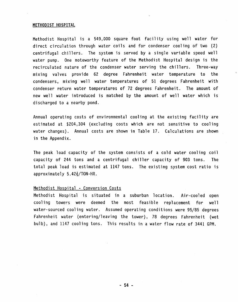
Methodist Hospital is a 549,000 square foot facility using well water for
direct circulation through water coils and for condenser cooling of two (2)
centrifugal chillers. The system is served by a single variable speed well
water pump. One noteworthy feature of the Methodist Hos pi ta 1 design is the
recirculated nature of the condenser water serving the chillers. Three-way
m1x1ng valves provide 62 degree Fahrenheit water temperature to the
condensers, mixing well water temperatures of 51 degrees Fahrenheit with
condenser return water temperatures of 72 degrees Fahrenheit. The amount of
new well water introduced is matched by the amount of well water which is
discharged to a nearby pond.
Annual operating costs of environmental cooling at the existing facility are
estimated at $204,304 (excluding costs which are not sensitive to cooling
water changes). Annual costs are shown in Table 17. Calculations are shown
in the Appendix.
The peak 1 oad capacity of the system consists of a co 1 d water coo 1 i ng coil
capacity of 244 tons and a centrifugal chiller capacity of 903 tons. The
total peak load is estimated at 1147 tons. The existing system cost ratio is
approximately 5.42¢/TON-HR.
Methodist Hospital - Conversion Costs
Methodist Hospital is situated in a suburban location. Air-cooled open
cooling towers were deemed the most feasible replacement for we 11
water-sourced cooling water. Assumed operating conditions were 95/85 degrees
Fahrenheit water (entering/leaving the tower), 78 degrees Fahrenheit (wet
bulb), and 1147 cooling tons. This results in a water flow rate of 3441 GPM.
- 54 -

Conversion first costs consist of a cooling tower, a tower pump, centrifugal chiller modifications, and piping/insulation. The operating data and cost estimates for the two (2) centrifugal chillers are shown below. The existing machines were manufactured with a smooth-tube design in the condenser bundle, as reflected in their high KW/TON. Conversion affords the opportunity to introduce state-of-the-art enhanced tubes, resulting in better electrical efficiencies (as shown below):
TABLE 14
CENTRIFUGAL CHILLERS ====================
==============================================================================
CHILLER 1 2 ====================== =========================== ==========================
MANUFACTURER
EXISTING TONS COND EWT COND LWT KW/TON
CONVERSION TONS COND EWT COND LWT KW/TON
CONVERSION COST* IMPELLER GEAR VESSEL
CARRIER
650 62 72
.932
650 85 94.8
. 722
$17 ,000 $ -0-$17,500
CARRIER
325 62 72
.912
325 85 94.7
.7385
$ -0-$ -0-$17' 500
==============================================================================
Conversion costs for a new cooling tower, a tower pump, and piping are shown
on the fo 11 owing page. The tower was assumed to be i nsta 11 ed on a s 1 ab at grade.
- 55 -
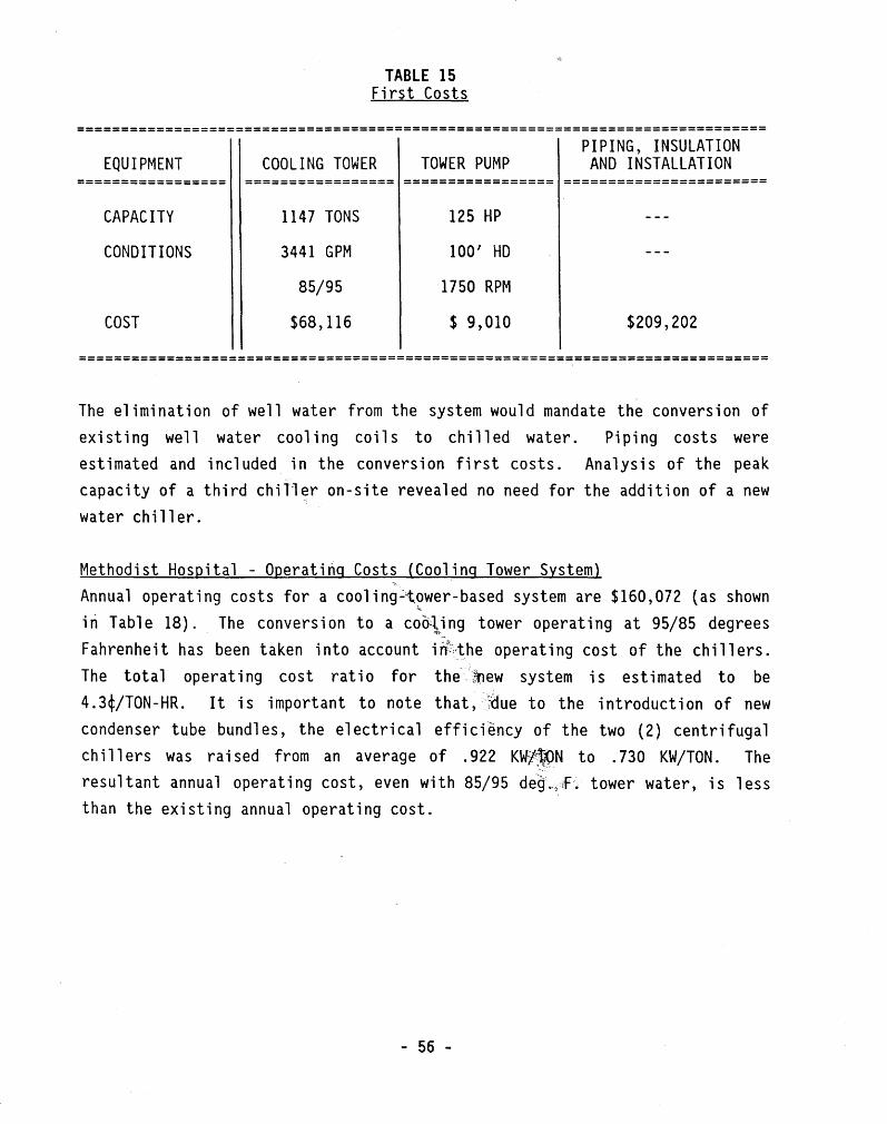
TABLE 15 First Costs
============================================================================== PIPING, INSULATION
EQUIPMENT COOLING TOWER TOWER PUMP AND INSTALLATION ================= ================= ================= =======================
CAPACITY
CONDITIONS
COST
1147 TONS
3441 GPM
85/95
$68, 116
125 HP
100' HD
1750 RPM
$ 9,010 $209,202
==============================================================================
The elimination of well water from the system would mandate the conversion of existing well water cooling coils to chilled water. Piping costs were estimated and inc 1 uded in the conversion first costs. Ana 1 ys is of the peak capacity of a third chiller on-site revealed no need for the addition of a new water chiller.
Methodist Hospital - Operating Costs (Cooling Tower System) " Annual operating costs for a cooling~t~wer-based system are $160,072 {as shown
in Table 18). The conversion to a cooling tower operating at 95/85 degrees "'~-'
Fahrenheit has been taken into account i n\~the operating cost of the chi 11 ers. The tot a 1 operating cost ratio for the- -·,~ew system is estimated to be 4. 3¢/TON-HR. It is important to note that, :~due to the introduction of new condenser tube bundles, the electrical efficiency of the two (2) centrifugal chi 11 ers was raised from an average of . 922 KW/jfPN to . 730 KW/TON. The
-,
resultant annual operating cost, even with 85/95 de~.,~~ tower water, is less than the existing annual operating cost.
- 56 -

Methodist Hospital - Cost Comparisons The operating cost comparisons for Methodist Hospital are:
TABLE 16 Operating Cost Comparisons
==================================================================
EXISTING (WELL WATER) CONVERSION (COOLING TOWER)
============================== ================================== ANNUAL OPERATING COST
$204,304
ANNUAL $/TON-HR
.0542
ANNUAL OPERATING COST
$160' 072
ANNUAL $/TON-HR
.0425
==================================================================
Methodist Hospital - Life Cycle Cost Comparison A life cycle cost analysis of the existing system is shown in Table 21. (Note that the age of the existing equipment is not taken into account and replacement costs of existing machinery are not included). The life cycle cost is based on a 20-year life, 8% discount rate, no sa 1 vage, 5% fuel escalation, and 4% water treatment cost inflation.
Life eye le costs for a system ut i l i zing a cool i ng tower to obtain cooling water are shown in Table 22. The first costs for converting to an air-cooled cooling tower appe~r in the tabulation. The total cost is a "present worth" cost (in 1989 dollars) of a system operating for 20 years and includes first costs. Note that the first cost of a cooling tower and condenser tube bundles has been off set by the imp roved performance of the compressori zed machines with the enhanced tubes, as reflected in the conversion life cycle cost below:
LI FE CYCLE COST
BASE SYSTEM (WELL WATER) ................... $3,048,723 CONVERSION (COOLING TOWER) ................. $2,728,128
- 57 -

TO WELL WATER COILS IATER rr S-7 • S-8 & S-12 TAEA 7WEH7
TO WELL WATER I I co1Ls s-1. r--111---~,--,----------------------- I S-2 a. S-3::.___----. NC l I • I I
-1 I I
I t r---- ----- i I I ! I o I
WELL PU&.F
i L------------j-- --,----- \1 I I ~RECIRCULATED I I I WELL IUTER
f I I
I t l I I I I I I
TO PONOC,---_J-------, I I I SRECIRCULATED I I t WELL WATER I I r- ______ J I t TO LAWN I J 0 I I ... I _J
roi • ;-CONO J l::J L=:~-r=I-:--------,---- -~~~ ~INKLER
D EVAP
I CHILLER #3 I 650 TON
\
CHILLED WATER (01 CLOSED LOOP I c,--.,...-CHWR---L ___ _
~H
D EVAP
I CHILLER #1 I 650 TON
~ -'-----
D EVAP
CHILLER #2
~325 TON
,_J

Annual Existing Well
TABLE 17 Operating Costs Water-Cooled Equipment
==============================================================================
PUMPING FACIL
WATER TREATMENT
COMPRESS. ELECTRIC
MI ELECTRIC
====================== ========== =========== =========== ========== =========
$14, $ $ 1
1 7,
I, 1
1
==============================================================================
==============================================================~===============
==========
METHOD I HOSPITAL
$10
1
$16,1
========
$
12
$1 19 $
=====-====
$1
1 l
$ 4, 1 $1 ,072
==============================================================================
- 59 -

TABLE 19 Annual Operating Costs
District Cooling
================================~·====================
FACILITY ANNUAL * TOTAL ==================== ========== ========== ===========
GAVIIDAE COMMONS $81,000 $81,000
======================================================
* Based on 360,000 annual TON-HOURS of cooling. Costs are not actual costs, rather they are relative costs for comparison with well water and cooling tower systems. The cost of maintenance, labor and capitol equipment has been excluded. Actual costs are $.3137/TON-HR.
TABLE 20 Annual Operating Costs
District Heating
==============================================================================
FACILITY ANNUAL STEAM HEAT PUMP CREDIT* TOTAL =================== ============ ============== =================== ==========
GAVIIDAE COMMONS $ 25,969 <$888> $ 25,081
==============================================================================
* Heat pumps provide additional capacity due to increased source water temps, compared with well water as a heat source.
- 60 -

)
=================== ========== =========== ============ =========!============
========== ============ ========= =========== ========== ========= ===========
7 '116 l 1
$ ,1 3
1,316, $ ,919
,116 2 ,212 1,
==============================================================================
- 61

TABLE 22 - CONTINUED
Life Cvcle Cost Summary Conversion to Air-Cooled Water Tower (20 Years, 8% Discount, No Salvage) (5% Fuel Escalation, 4% Water Treatment Inflation)
==============================================================================
FACILITY
MISC ELECTRIC COST
COOLING TOWER ELECTRIC COST
MAKE-UP WATER & SEWER COST TOTAL PRESENT WORTH
========== =========== =========== =========== ===============================
GENERAL $ -0- $ 58,178 $176,401 $ 2,998,354 MILLS
GAVI IDAE $ -0- $ 21,981 $ 93,628 $ 1,044,005 COMMONS
HONEYWELL $ 742,975 $259,609 $444,460 $ 9,105,832 AVIONICS
METHODIST $ -0- $ 74,596 $176,401 $ 2,728,128 HOSPITAL
==============================================================================
TABLE 23 Life Cycle Cost Summary
Conversion to District Cooling (20 Years, 8% Discount, No Salvage)
(4% Purchased Chilled Water & Steam Inflation) [Annual Chilled Water Costs: (.2250)$/TON-HR x 400 TONS x 900 FL HRS]
[Annual Steam Costs: $5.51/1000 LBS x 4.72 MMLBS]
==============================================================================
HEAT FACILITY EXCH
FIRST COST
PIPING FIRST COST
CHILLED WATER COST
STEAM COST TOTAL PRESENT WORTH
========== ========= ========= ============ ========== =======================
GAVI IDAE COMMONS
$26,700 $11,160 $1,115,937 $345,541 $ 1,499,338
==============================================================================
- 62 -

III. DESIGN ALTERNATIVES TO •ONCE-THROUGH• WELL WATER USAGE
OVERVIEW
The concept of mechanical cooling operates on the principal of energy transfer from a heat source to a heat sink. The atmosphere, the ground, surface water or ground water are all val id heat sinks in the operation of mechanical cooling equipment. Re-stated another way, the environmental cooling of a space requires that there be a means of rejecting that heat. Ground water is one of those means. It can be circulated through a building directly or used to pick up heat from a refrigerant process.
Those applications which currently use ground water for cooling purposes could possibly convert those systems to open- loop water systems, such as conventional, air-cooled, cooling towers. They could also conceivably convert from well water to purchased municipal water, which is primarily surface-water sourced. Although technologies exist which utilize air-cooled equipment without open water 1 oops, their e 1 ectri ca 1 efficiency is much 1 ower than water-cooled systems. These methods are, therefore, cost prohibitive for large systems (100 tons and above).
Of the air-cooled options, the most feasible two (2) are:
1) User owner-and-operated, open cooling towers, and 2) District cooling.
Open Cooling Towers. Inherent in the operation of mechanical cooling equipment is the generation of heat. The most efficient and effective method of rejecting that heat is with water-cooling of the equipment. The component which figures in the conversion from well water, but allows continued usage of
- 63 -
I
11

water-cooled equipment, is the open, air-cooled, cooling tower. Cooling towers derive their primary cooling effect from the evaporation that takes place when air and water are brought into direct contact They achieve this effect by exposing the maximum water surface to the maximum flow of air. This is accomplished by introducing a spray of water from the top of the tower. The downward fl ow of water droplets is countered by the upward fl ow of air, usually by propeller fans which induce the air draft The contact time of the falling water is increased by the introduction of "fill" (or slats) inside the tower which impedes the fl ow of the water droplets and increases their surface area by breaking them up.
The evaporation of water causes a steady increase in the concentration of total dissolved solids in the circulated water. Control of these undesirable solids in a cooling tower is by continual "blowdown" of a certain amount of water, which is made up with fresh water. Water "make-up" refers to the total amount of water required to make up for evaporative, drift, and bl owdown lasses. For a system operating at a 10-degree Fahrenheit range of water entering/leaving the cooling tower, and with blowdown requirements allowing a 3:1 ratio contaminant concentration of CIRCULATION water to MAKE-UP water, the percent of MAKE-UP water to CIRCULATION water may range anywhere from 1.22% to 5%. This water can be sourced from municipal water supplies or via well water, depending on the economics and availability.
District Cooling. The feasibility of alternatives available to the user must be ana 1 yzed on an ind iv i dua 1 basis. Downtown users in Mi nneapo 1 is have an option for purchasing district chilled water which others do not. The development of a district cooling system in downtown St. Paul is under consideration at this time, based on District Energy St. Paul's estimate of twenty · ( 20) potent i a 1 users. The economics of such a system are currently unknown. By contrast, downtown users may not have the space or the roof structural integrity to accommodate a cooling tower, eliminating that option.
1 JOHN C. HENSLEY, ED., COOLING TOWER FUNDAMENTALS, MARLEY COOLING TOWER CO., MISSION, KANSAS, 1982.
- 64 -

The economic impact on the user for conversion from well water depends on the facility's design. New equipment or modification of existing equipment may be warranted in the conversion. Energy efficiencies and/or capacities may decrease. In i so 1 ated cases where outdated equipment is at the end of its service 1 if e, conversion affords the opportunity to upgrade this equipment. The analysis of Methodist Hospital in the previous· section illustrates an example of improved electrical efficiency even at the higher condenser water temperatures of the conversion. Structural design .loads of the roof must be considered for roof-mounted cooling towers.
The ramifications which reach beyond the individual user are the added electrical requirements and environmental costs. Electrical utility suppliers may have an added 1 oad, due to the increased e 1 ectri ca 1 consumption. This will have an environmental impact as these utilities consume more natural gas, generate more nuclear energy or burn more coal.
The conversion from well-water-based environmental heating/cooling systems to alternative approaches mandates analyses on an individual basis. Genera 1 i zat ions of alternatives or costs are difficult to ascertain. The rami fi cations for el ectri cal utility supp 1 i ers and the envi ronmenta 1 impacts of conversion may warrant further investigation.
- 65 -

METHODS & MEASURES OF SYSTEM PERFORMANCE AND IMPROVEMENT FOR 11 0NCE-THROUGH 11
APPLICATIONS
analysis "once-
is
the efficient utili 11 envi ronmenta 1
can
in
ion
ciencies (i .. ,
When water efficiency (described in is efficiency (described in KW/TON), clear Systems which are efficient on both seal es reside
's 1 resources measures
ir
ti thin an "envel
ue
efficient usage, as illustrated by the shaded area Fi 5.0. The placement of the "Envelope of Allowable Well Water Usage" may conducted on the basis of the perceived importance of the two (2) variables.
The advantages of such a measure are two-fold:
1) The proposed "envelope" allows for a method by which the relevant importance of water efficiency versus electrical efficiency may be weighed; and
2) The values for the units of measure are readily obtainable.
The units of measure would be obtained based on the following criteria:
TON: Peak Day Load Cooling Capacity (in Tons) for the System; where Tons 12,000 BTU/HR. This would be Peak Day Load Tons, not Installed Tons, and would include well water coil capacity.

GPM: Gallons Per Minute; The design GPM of well water required by the System to achieve the Peak Day Load described above. For cooling towers utilizing well water, this would be the make-up GPM of well water.
KW: The KW input required by the System to achieve the Peak Day Load described above. This would be the KW which is sensitive to water temperature or water vo 1 ume ( i . e., we 11 ·water pumps, condenser water pumps, tower fans, and compressorized equipment). Compressorized equipment would include chillers, heat pumps, condensing units, packaged cooling units, etc. Excluded from the KW value would be chilled water pumps, air handler motors, and any other KW inputs which are not sensitive to well water usage.
The equation for water which relates capacity {BTUH) to GPM and temperature difference is:
BTU/H = 500 x GPM x TD
or, restated:
TONS = GPM x TD 24
Hence, a System ich culls a high temperature difference from the water results in a low for the same capacity. The we 11 water temperature difference imparted by the System is, thereby, reflected in the unit 11 GPM/TON 11
•
The unit of measure "KW/TON" describes the electrical effici System. is can be related to electrical cost by tiplyi l $/KW charge. age of KW/TON allows users to be electrical ciency and to be compared on an e is' to the local utility's rates.
- 67 -
the user's
on their regard

==================
* * * * *
====== A B c D E F G
---- >
NOTE: THESE ===== EFFICI
T.
10.0 0
.0 10.0 17 .5 10.0
.0 15
1
51.5 1 .
.2 10.5
.0
.9
INCLUDE WATER . ' ARE
* *
I <-~
========= ==========
$1. 91

z 0 I-
--~ a... CJ
I
>-() z w ()
LL LL w a: w I-<t:: s
2
1.5
1
0.5
0 0.2 0.4 0.6 0.8 1
ELECTRIC EFFICIENCY - KW I TON
Potential Envelope.
FIGURE 5.0
PROPOSED ENVELOPE METHOD OF ALLOWABLE WELL WATER USE MEASURE
1.2

The systems described in Table 24 provide the basis for comparison of relative efficiencies. They are, however, "pure" systems; whereas, in practice, a combination of approaches may be employed. Analyses of the actual permits issued in the State reveal the fo 11 owing number of permi ttees whose use adheres to the criteria established in the examples:
TABLE 25 Comparison With (7) Tvpical Systems
====== SYSTEM ------------
A B c D E G
====================== # OF ACTUAL PERMITTEES ======================
0 8
37 16 14 17
The standard, as proposed in this Section, would be applied based on cooling design capacities only.
A strategy which can serve to increase the water use efficiency of the system is the use of variable volume pumping. The principle thrust in the utilization of variable speed/variable volume pumping is the potential for water and energy savings. A variable volume pumping design requires that there be two-way modulating valves downstream of the pump which automatically apportion the water to the coils or vessels in accordance with their heating or cooling needs. Hence, the user only pumps that quantity of water which the system calls for, achieving a savings in electrical KW consumed and in total gallons per year pumped.

A variation on the use of variable volume pumps is the utilization of constant volume pumps in concert with two-way modulating valves at the coils and
vessels as described above. As the valves close, the capacity requirement decreases. Proper care must be taken in the se 1 ect ion and app 1 i cation of constant volume pumps on such a system. The pump curve is described by Total Head (feet) versus Capacity (GPM) and should b.e "flat" {i.e., allowing larger changes in capacity for a smaller change in head). Flat curve pumps offer a more stab 1 e pressure drop ratio as va 1 ves c 1 ose, thereby providing better v a 1 ve contro 1 . The adv ant age of this type of cont ro 1 is that, as the pump "rides its pump curve", the horsepower requirements change. Thus, an electri energy savings is achieved as horsepower decreases. Total pump volume (GPM) likewise decreases as the horsepower decreases, achieving a savings in total gallons per year pumped.
Proper maintenance l ements
ves
the components 11 promote system
efficiency by ensuring ition. For example,
oats must freely. The use 11 evate the importance the operation ntenance components de a means to
measure their condition and effectiveness.
- 71 -

FEASIBILITY AND IMPACT OF CONVERSIONS
Capacity Water sourced from underground aquifers is typically 50 - 55 degrees Fahrenheit. By contrast, water sourced from open air-cooled towers typically leaves the tower at 85 degrees Fahrenheit. When the cooling water temperature of compressorized mechanical cooling equipment changes from the SO-degree Fahrenheit range to the 85-degree Fahrenheit range, the capacity of the compressors decreases by approximately 103. This is due to the change in the condensing temperature of the equipment at the higher condenser cooling temperatures, and the resultant decrease in capacity on the "Unit versus Condensing Temperature" curve. The compressors are 1 ess efficient at the higher condensing temperatures ( i . e., they require more e 1 ectri ca 1 energy input for the same output). However, this effect is mitigated by the fact that the temperature of the cooling water leaving the tower "floats" and can be as low as 60 to 70 degrees Fahrenheit, depending on atmospheric condit~ons. The efficiency of smaller equipment is measured by its Energy Efficiency Ratio (EER), which is expressed in BTUH/(Output) per Watt (Input). The water source heat pumps used in Gaviidae Commons experience the following cooling EER's at two (2) different source temperatures:
TABLE 26 Water Source Heat Pump EER's
==================================================================
CAPACITY (TONS)
EER@ 70/85 DEG. F. (EWT/LWT)
EER@ 85/95 DEG. F. (EWT/LWT)
================== ======================= =======================
1
2
3
4
5
11. 9
12.6
12.3
12.0
12.1
11.0
11. 7
11.3
11.0
11. 2
==================================================================

The electrical efficiency of large equipment is often measured by KW (Input) versus capacity (output) and is expressed in KW/TON. A comparison of reciprocating water chi 11 ers at two (2) condenser water temperature 1 evel s reveals the following:
TABLE 27 Reciprocating Water Chiller (KW/TON)
=================================================================
========== ======== ============ ========= ======== ============
1
1
.3
1 . 5
.8
4
11 .8
1
1 .
.1
.1
.4
1.5
1 6
1
=================================================================
is a 1
it eavi i 11
Centri illers and centri heat experience icular ems the condenser water temperature is changed. The components of these
machines are computer-selected to derive specific performance objectives, based on selected operating conditions. While centrifugal compressor machines are capable of high efficiencies, changes to the condensing water temperature create conditions under which the machine either cannot function or functions at a lower electrical efficiency. A higher condenser water temperature requires a higher refrigerant condensing temperature. Concomitant with a higher condensing temperature is a higher pressure. In order to achieve this, a higher impeller tip speed is required. Based on the design principles of the Manufacturer, a larger impeller diameter or higher speed gear is employed.
- 73 -

These components are machined to very close tolerances and are, therefore, expensive. Quite often condenser vessels must also be changed to accommodate the higher water volume (GPM) of the 85/95 degree Fahrenheit condenser water temperature. The change in condenser vessels can, however, produce a dramatic improvement in system performance if old "smooth tube" designs are rep 1 aced with "enhanced fin" designs, as witnessed in the Methodist Hospital scenario discussed in Section II. The age of such equipment is also a factor. Machines that are old enough to have "smooth tube" designs may be near the end of their service life and the entire machine would be replaced with a more electrically-efficient machine. Conversion to a cooling tower system affords the opportunity to upgrade the system. Examples of capacity and electrical efficiency for centrifugal chillers at different condensing temperatures are shown below:
TABLE 28
CENTRIFUGAL CHILLERS (KW/TON) =============================
==============================================================================
MACHINE APPROX. 50/75 DEG. F. EWT/LWT APPROX. 85/95 DEG. F. EWT/LWT ============ ================================ ================================
A B c D
Tons
360 300 500 263
KW/Ton ------
.493
.413
.382
.414
Tons KW/Ton ------
319 .603 292 .644 447 .615 263 .673
============ ================================ ================================
Facilities which currently utilize well water for circulation through cooling coils would have to convert to chilled water, or DX refrigeration systems. In facilities with reserve capacities of compressorized equipment, the increased operating levels would be called upon to provide the load previously satisfied by the well water coils. If reserve capacities of existing chillers were not available, addditional water chillers or replacement equipment with greater capacities would be required.
- 74 -

Space and Structural limitations
The space and structural rami fi cations install ion new cooling
d di c l i can be
ei
i ve s i nee is no di
is area.
si
on
, are on l
- 75 -

TABLE 29
COAL-FIRED ANNUAL ADDITIONAL EMISSION RATES ===========================================
so 58,867 LBS/YR NO 44,150 LBS/YR PARTICULATES: 2,453 LBS/YR CO 3.087 x 10 LBS/YR THERMAL EFFECTS: 2.87 x 10 BTU TO AIR & WATER/YR
Note that the figures above relate to a 5 MW demand. The range of 5 to 15 MW
additional capacity is based on a "worst-case" scenario, wherein all well
water systems are converted to alternate technologies. The "Geothermal
Survey" data reveals that the "worst-case" scenario results in a 7 .33 MW
demand, as shown on the fo 11 owing page. Po 1 i c i es which encourage
modifications of some well water designs to improve water efficiency would
mitigate this effect.
Environmental imp acts from the operation of open coo 1 i ng towers are both
technical and aesthetic in nature. The use of cooling tower technologies
shifts the medium of heat rejection from water systems to air. Aesthetic
concerns relate to the evaporative water loss which may produce a large vapor
plume. Open cooling towers produce airborne noise, which may pose design or
1 ocat ion prob 1 ems. A further concern may be the addition of refrigerating
machines, as required, to replace the capacity lost from existing systems.
These new machines may potentially contribute to the earth's ozone layer
depletion resulting from the chlorofluorocarbons used in their design,
depending on the refrigerant of the replacement machine.

was mani i
)
============================================================================== I
=========== ======== ======== =========== ======== ============= =============
$
$
==============================================================================
ive
e
l
increase
1 ons
11' as
most

Analysis of the electrical impact of conversion reveals that the elimination of Cold Water Coil Systems may result in an additional 3.56 megawatts of local utility capacity. This is due to the inherent electrical efficiencies of their existing operation, as all they currently pay for is pumping KW in order to achieve environmental cooling. These systems, which operate at approximately .11 KW/TON, would have to be replaced with systems which require mechanical cooling at .50 KW/TON.
Further investigation reveals that a total ban of all well water-based systems may require an additional 7.3 megawatts of electricity generation over current electrical consumption.
Recommended Time Frame A recommended time frame for the conversion of well water-based systems to more water-efficient systems might be tied to the estimated remaining life eye 1 e of the system, or components thereof. If a tot a 1 conversion of a 11 systems is desired by a certain date, this could be accomplished with. the introduction of the following requirements:
a) Twenty (20) years as a final date for the conversion of all systems from well water. This would see the current systems through the Year 2010.
b) New or ammended permits would be required, as part of their application, to provide estimates of remaining life cycles of their equipment.
c) The permits would be in effect through the life of the equipment, at which time conversion would be required.
This approach would pro vi de existing Permi tees ti me to assess the la test developments and state-of-the-art technologies in the chlorofluorocarbon (CFC) debate. Such an i ncrementa 1 approach would a 11 ow users the opportunity to coordinate their purchases with the develpment of less ozone-depleting refrigerants. Local electrical utilities could likewise approach any increased KW demand in an incremental fashion.

on is
is a means
===================================~====~=====================================
IL IL .,.., __________
..... - - .... - ......... ------- ..., _________ ----------- ------- ------- ---------General 2925 1284 2. General 58.0 1284 .045 Mi 11 s Mills
Gaviidae 2740 912 3.00 Gaviidae 36.5 912 .040 Commons Commons
Honeywell 1797 1507 1.19 Honeywell 61.0 1350 .045 Avionics Avionics
Methodist 3412 . 1147 2.97 Methodist 51.8 1147 .045 Hospital Hospital
==============================================================================
* COOLING TOWER MAKE-UP WATER GPM
th itions usi a
ci a is L
eld
ting as a
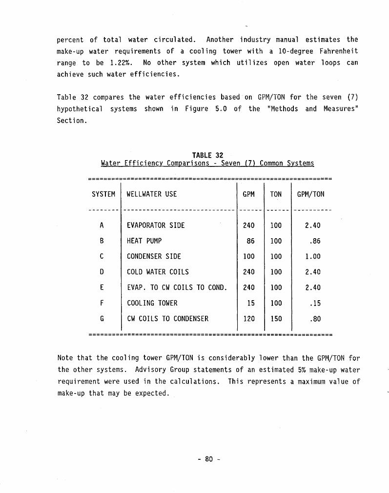
percent of total water circulated. Another industry manual estimates the make-up water requirements of a cooling tower with a 10-degree Fahrenheit range to be 1. 22%. No other system which utilizes open water 1 oops can achieve such water efficiencies.
Table 32 compares the water efficiencies based on GPM/TON for the seven (7)
hypothetical systems shown in Figure 5.0 of the "Methods and Measures" Section.
TABLE 32 Water Efficiency Comparisons - Seven {7) Common Systems
===============================================================
SYSTEM WELLWATER USE GPM TON GPM/TON
A EVAPORATOR SIDE 240 100 2.40
B HEAT PUMP 86 100 .86
C CONDENSER SIDE 100 100 1.00
D COLD WATER COILS 240 100 2.40
E EVAP. TO CW COILS TO COND. 240 100 2.40
F COOLING TOWER 15 100 .15
G CW COILS TO CONDENSER 120 150 .80
===============================================================
Note that the cooling tower GPM/TON is considerably lower than the GPM/TON for the other systems. Advisory Group statements of an estimated 5% make-up water requirement were used in the calculations. This represents a maximum value of make-up that may be expected.
- 80 -

in
e
i1 i zi
conserve
A further analysis water-efficient (
s a
through cooli coils ( temperature di across coils condenser dictates the condenser requires 1
s cooling
l ivers
hi
l
ar a 1
an
System is one i
ser are
t across
ion. acros
l
systems
1 cases
it ions is.
most
t
i 11 er,
coils receive
coi
il 1
rsi

OPERATING COST COMPARISONS
Well Water versus Municipal "Surface" Water There are currently no restrictions on the utilization of large volumes of municipal water. Hence, any well water permittee is free to substitute municipal water for well water in their systems. The water rates for the
cities of Minneapolis and St. Paul (as of December, 1989) are:
MINNEAPOLIS $ .85/750 GALLONS $1.133/1000 GALLONS
ST. PAUL .......... FIRST 37,400 GALLONS= $1.20 /1000 GALLONS NEXT 336,600 GALLONS = 1.173/1000 GALLONS OVER 374,000 GALLONS = 1.146/1000 GALLONS
The figures below are for existing well water designs, without conversion to alternate systems. When municipal water is substituted for well water (in the four ( 4) facilities analyzed in Section II), the annual operating cost ratio comparisons, based on an average $1.14/1000 Gallons for City water, are:
TABLE 33
==============================================================================
FACILITY WELL WATER OPERATION
($/TON-HR) MUNICIPAL WATER OPERATION
($/TON-HR)* MGY ==================== ====================== =========================== ======
General Mills
Gaviidae Commons
Honeywell Avionics
Methodist Hospital
.0340
.0619
.0283
.0542
.1413
.9313
.0742
.1213
238.0
525.6
346.3
222.0
==============================================================================
Note: * Annual cost increases due to decreased equipment efficiencies are not included.
- 82 -
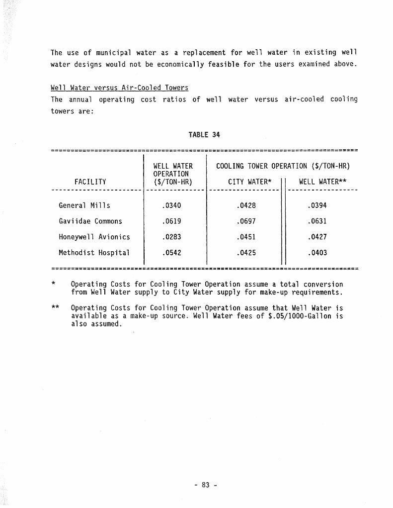
The use of municipal water as a replacement for we 11 water in existing we 11 water designs would not be economically feasible for the users examined above.
Well Water versus Air-Cooled Towers The annua 1 operating cost ratios of we 11 water versus air-cooled cooling towers are:
TABLE 34
==============================================================================
WELL WATER COOLING TOWER OPERATION ($/TON-HR) OPERATION
FACILITY ($/TON-HR) CITY WATER* WELL WATER** ----------------------- --------------- ------------------ ------------------
General Mills .0340 .0428 .0394
Gaviidae Commons .0619 .0697 .0631
Honeywell Avionics .0283 .0451 .0427
Methodist Hospital .0542 .0425 .0403
==============================================================================
*
**
Operating Costs for Cooling Tower Operation assume a total conversion from Well Water supply to City Water supply for make-up requirements.
Operating Costs for Cooling Tower Operation assume that Well Water is available as a make-up source. Well Water fees of $.05/1000-Gallon is also assumed.

Well Water versus District Cooling The annual operating cost ratios of well water versus district cooling (purchased chilled water only) are:
TABLE 35
==============================================================================
FACILITY WELL WATER OPERATION
($/TON-HR) DISTRICT COOLING OPERATION
($/TON-HR) ======================== ========================= ===========================
Gaviidae Commons .0619 .2250
==============================================================================
* Annual TON-HOURS are estimated to be 360,000 with District Cooling, thereby reducing annual costs as chilled water is purchased to meet actual daily requirements.
- 84 -

FEE STRUCTURES
A water fee is desired that wil 1 make we 11 water systems and conversion
systems equal in cost. In the analysis that follows, the conversion system to
which other systems wi 11 be compared sha 11 be an air-coo 1 ed, open-coo 1 i ng
tower.
Two (2) costs shall be assessed to each systm:
a) Electric Operating Cost, and
b) Water Usage Cost
Hence, a water fee is desired such that the following equation can be
satisfied:
ELEC. COST + WATER COST = FIXED COST
EQUATION
NUMBER 1.0
where; FIXED COST is the desired base cost to which other systems will be
compared.
When each cost is divided by "TONS" (i.e., costs are analyzed on a "per ton"
basis), the equation becomes:
ELEC [__j__] + WATER [__j__ x GAL] = FIXED [__j__] TON GAL TON TON
EQUATION
NUMBER 2.0
Earlier in this Study, the concept of an "envelope" of allowable usage was
proposed. This "envelope" was based on seven (7) typical systems, of which
cooling towers was one. We sha 11 re-introduce those systems and tabulate
their $/TON electric costs and their GAL/TON usage on the following pages.

TABLE 36
"$/TON" AND "GAL/TON" FOR SEVEN SYSTEMS =======================================
==================================================================
SYSTEM DESCRIPTION $/TON (ELECTRIC) GAL/TON
======== ===========~================ ================== =========
A CHILLED WATER .0232 1
B HEAT PUMP .0489 51.6
c CONDENSER .0204 60
D COOLING COILS .0047 144
E EVAP. TO COILS TO COND. .0191 144
F COOLING TOWER .0369 9
G COILS TO CONDENSER .0247 48
==================================================================
Equation 2.0 was used to calculate the required $/GAL that makes each of the above systems equal to the cooling tower operation cost of $.0369/TON:
TABLE 37
"$/1000-GAL" - FEE THAT EQUATES WELL SYSTEMS TO COOLING TOWERS ==============================================================
==============================================
SYSTEM $/GAL $/1000-GAL _
============·= ============== =================
A B c D E F G
.000095 Negative Fee .000275 .0002236 .0001236
-0 .000254
.095 Negative Fee .275 .224 .124 -0-
. 254
==============================================
- 86 -

Tables 38 and 39 i 11 ustrate the effect of the State's existing water fee
structure on the above systems:
SYSTEM
A B c D E F G
====== SYSTEM ======
A B c D E F G
Conclusion
TABLE 38
EFFECT OF WATER FEES AT $.05/1000-GALLON ========================================
================ =============== =========== [ C $/TON] + ================
.
.0191
.0369
.0247
GAL/TON] x [FEE ===============
.0
. 6
.0
.0 144.0
9.0 48.0
TABLE 39
=========== . .00005 .00005 .00005 .00005 .00005 .00005
=
EFFECT OF WATER FEES AT $.10 AND $.15/1000-GALLON =================================================
===================== ===================== TOTAL @ $.10/1000-GAL TOTAL @ $.15/1000-GAL ===================== =====================
.0376 .0448
.0541 .0566
.0264 .0294
.0191 .0263
.0335 .0407
.0378 .0383
.0295 .0319
===========
===========
• 5 .0234 .0119 .0263 .0374 .0271
============= RELATION TO F =·============ EXCEEDS EXCEEDS LESS LESS APPROX. EQUAL
LESS
Fee structures can be proposed that wi 11 provide economic incentives for a
user to convert from a well water system to an open cooling tower system. The
fo 11 owing synopsis i 11 ustrates the water fees required to make comparative
systems equal in operating costs to cooling towers:
- 87 -

SYSTEM ======
A B c D E
(F) G
TABLE 40
FEE SYNOPSIS ·===========
======================= DESCRIPTION ======================= Chilled Water Heat Pump Condenser Cool i ng Coil s Evap. to Coils to Cond. Cooling Tower Coils to Condenser
========================= FEE REQUIRED ($/1000-GAL) =========================
.095 NONE .275 .224 .124
.254
At a fee of 15¢/1000-GAL, Systems "C" and "G" continue to be less expensive to operate than cooling towers. These systems al so fall within the proposed "envelope" of a 11 ow able we 11 water usage, as proposed previously in this Study.
At a fee of 10¢ to 12¢/1000-GAL, System "E" is also less expensive to operate than cooling towers and could fall within the allowable "envelope" if the line were raised to include it.
In each of the above examples (15¢ and 12¢/1000-GAL), cooling coils would also be less expensive to operate. A ban would be required to exclude them from operation.
- 88 -

APPENDIX TABLE OF CONTENTS *
GENERAL CALCULATIONS
ASSUMPTIONS {ELECTRIC COSTS, PUMPING FORMULAS)
LIFE CYCLE COST COMPARISONS
WATER TREATMENT
COOLING TOWERS - WATER MAKE-UP
ECONOMIC AND KW IMPACT
TOTAL ELECTRIC REQUIREMENTS
ENVIRONMENTAL IMPACT - NSP
TABLE 24
TABLE 33
TABLE 34
FACILITY ANALYSIS - (GENERAL MILLS, GAVIIDAE COMMONS HONEYWELL AVIONICS, METHODIST HOSPITAL)
SUMMARY - ANNUAL OPERATING COSTS
TON-HOURS ~~·
WELL WATER O~ERATING COSTS
CONVERSION OPERATING COSTS
PEAK DAY TONS
TOTAL FIRST COSTS - CONVERSION
MANUFACTURER OPERATING DATA: CHILLERS, COMPUTER ROOM UNITS, HEAT PUMPS, DISTRICT COOLING & HEATING
TOWER SELECTION
GEOTHERMAL SURVEY INFO
* COPIES AVAILABLE UPON REQUEST
- 89 -
