tjernlund products, inc. products inc., ... troubleshooting guide ... 1/8"-npt pipe plug to the...
TRANSCRIPT
TJERNLUND PRODUCTS, INC.1601 Ninth Street • White Bear Lake, MN 55110-6794
PHONE (800) 255-4208 • (651) 426-2993 • FAX (651) 426-9547
Visit our web site • www.tjernlund.com
©2015 TJERNLUND PRODUCTS, INC. ALL RIGHTS RESERVED. P/N: 8505032
WIRING OPTIONS
SEE VP-2F, VP-3F OR
WHKE MANUAL FOR
DO NOT ALTER
GAS SUPPLY
INTO PRESSURE TAP PORT.
GAS PRESSURE SWITCH
GAS CONTROL VALVE
TRADITIONAL
PILOT GAS LINE
INSTALL BRASS 1/8-NPT MALE
x 1/4" COMPRESSION FITTING
THERMOCOUPLE
BURNER GAS LINE
COMMON
MUST BE MOUNTED VERTICALLY.
GAS PRESSURE SWITCH DIAPHRAGM
IMPORTANT:
BRASS 1/8-NPT MALE x 1/4"
COMPRESSION FITTING
1/8-NPT BLACK PIPE TEE
1/8-NPT PIPE PLUG - NEW
PRESSURE TAP PORT
NORMALLY OPEN
MOUNTING HOLES
IMPORTANT:
AR
HO
TW
AM V
CA
TIO
N
GAS
VALVE
THERMOSTAT / GAS CONTROL
TO PRESSURE TAP FITTING OF
1/4" OUTSIDE DIAMETER
ALUMINUM TUBING - CONNECT
VALVE.
JUNCTION ADAPTER
JA1 THERMOCOUPLE
WIRES FROM LINEAR
LIMIT ROLLOUT SWITCH
SEE VP-2F, VP-3F OR
WIRING OPTIONS
RED
WHITE
NEW THERMOPILE STYLE
GAS CONTROL VALVE
PILOT GAS LINE
BURNER GAS LINE
LONG MALE NIPPLE INTO
INSTALL 1/8 - NPT, 2"
FIGURE 8050053 8/13/15
IMPORTANT:
PRESSURE TAP PORT.
GAS SUPPLY
DO NOT ALTER
FITTING INTO COUPLER.
INSTALL BRASS 1/8 - NPT
MALE x 1/4" COMPRESSION
INSTALL 1/8 - NPT
COUPLER
MOUNTING HOLES
NORMALLY OPEN
PRESSURE TAP PORT
1/8-NPT PIPE PLUG - NEW
1/8-NPT BLACK PIPE TEE
VALVE.
ALUMINUM TUBING - CONNECT
1/4" OUTSIDE DIAMETER
TO PRESSURE TAP FITTING OF
THERMOSTAT / GAS CONTROL
COMPRESSION FITTING
BRASS 1/8-NPT MALE x 1/4"
IMPORTANT:
GAS PRESSURE SWITCH DIAPHRAGM
MUST BE MOUNTED VERTICALLY.
COMMON
GAS PRESSURE SWITCHLIMIT ROLLOUT SWITCH
WIRES FROM LINEAR
HEATER
WATER
WIRE NUTS
BY OTHERS
WH
ITE
THERMOCOUPLE JUNCTION
ADAPTER IS NOT USED
WHKE MANUAL FOR
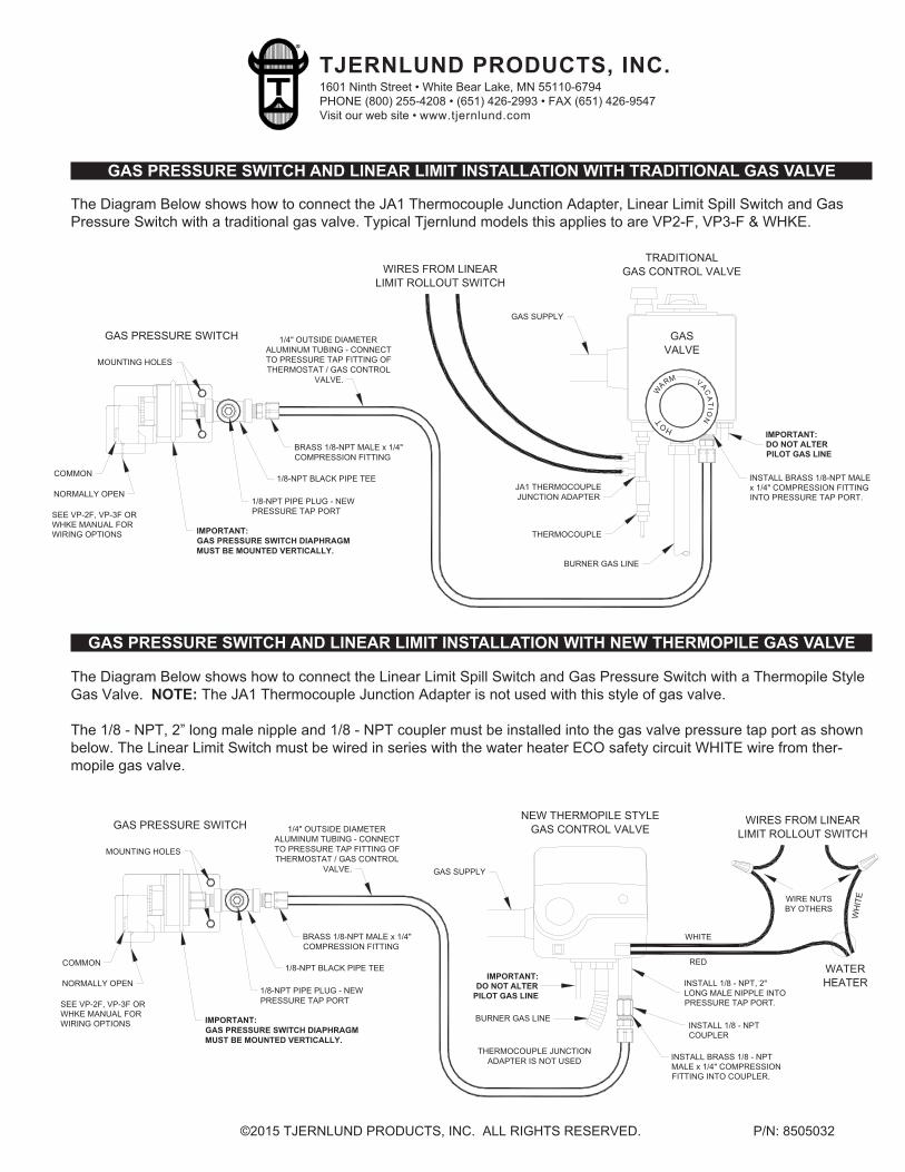
The Diagram Below shows how to connect the JA1 Thermocouple Junction Adapter, Linear Limit Spill Switch and Gas
Pressure Switch with a traditional gas valve. Typical Tjernlund models this applies to are VP2-F, VP3-F & WHKE.
The Diagram Below shows how to connect the Linear Limit Spill Switch and Gas Pressure Switch with a Thermopile Style
Gas Valve. NOTE: The JA1 Thermocouple Junction Adapter is not used with this style of gas valve.
The 1/8 - NPT, 2” long male nipple and 1/8 - NPT coupler must be installed into the gas valve pressure tap port as shown
below. The Linear Limit Switch must be wired in series with the water heater ECO safety circuit WHITE wire from ther-
mopile gas valve.
GAS PRESSURE SWITCH AND LINEAR LIMIT INSTALLATION WITH NEW THERMOPILE GAS VALVE
GAS PRESSURE SWITCH AND LINEAR LIMIT INSTALLATION WITH TRADITIONAL GAS VALVE
Rev. 07/07 Copyright © 2007, Tjernlund Products, Inc. All rights reserved. P/N 8504140
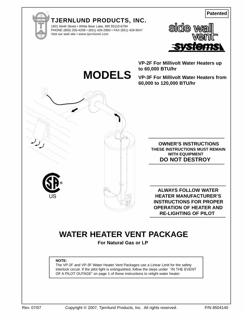
NOTE: The VP-2F and VP-3F Water Heater Vent Packages use a Linear Limit for the safety interlock circuit. If the pilot light is extinguished, follow the steps under “IN THE EVENTOF A PILOT OUTAGE” on page 1 of these instructions to relight water heater.
OWNER’S INSTRUCTIONSTHESE INSTRUCTIONS MUST REMAIN
WITH EQUIPMENTDO NOT DESTROY
ALWAYS FOLLOW WATERHEATER MANUFACTURER’S
INSTRUCTIONS FOR PROPEROPERATION OF HEATER AND
RE-LIGHTING OF PILOT
WATER HEATER VENT PACKAGEFor Natural Gas or LP
MODELSVP-2F For Millivolt Water Heaters upto 60,000 BTU/hr
VP-3F For Millivolt Water Heaters from60,000 to 120,000 BTU/hr
PatentedTJERNLUND PRODUCTS, INC.1601 Ninth Street • White Bear Lake, MN 55110-6794PHONE (800) 255-4208 • (651) 426-2993 • FAX (651) 426-9547Visit our web site • www.tjernlund.com
Tjernlund Products welcomes your comments and questions. Address all correspondence to: Customer Service, Tjernlund Products Inc., 1601 Ninth Street, White Bear Lake, MN 55110-6794 or email us at [email protected].
TABLE OF CONTENTS
In The Event of a Pilot Outage ........................................................................................................................................1Typical Installation ...........................................................................................................................................................2Sequence of Operation ...................................................................................................................................................2Installation Restrictions....................................................................................................................................................3Actuation and Safety Controls Installation ......................................................................................................................3
Gas Pressure Switch ...................................................................................................................................3 - 4Linear Limit Spillage Sensing Switch ................................................................................................................4 Thermocouple Junction Adapter .......................................................................................................................5
Vent Hood .......................................................................................................................................................................5Code Restrictions & Termination Clearances ...................................................................................................5Vent Hood Installation .......................................................................................................................................6
Power Venter Installation.................................................................................................................................................6Code Requirements and Installation Restrictions............................................................................................ 6Power Venter Installation.............................................................................................................................6 - 7
Electrical Connections .....................................................................................................................................................7Control Cord Routing.................................................................................................................................. 7 - 8Actuation and Safety Control Circuit Connections............................................................................................8
Operation Circuit Check ..................................................................................................................................................8 Safety Interlock Test ........................................................................................................................................................8Ladder Wiring Diagram ...................................................................................................................................................9Combustion Air Test.........................................................................................................................................................9Performance Curves......................................................................................................................................................10Troubleshooting Guide ...........................................................................................................................................11 - 12Maintenance ..................................................................................................................................................................13How to Obtain Service Assistance & Warranty .............................................................................................................13Replacement Parts List .................................................................................................................................................13Vent Hood Mounting Template ......................................................................................................................................14
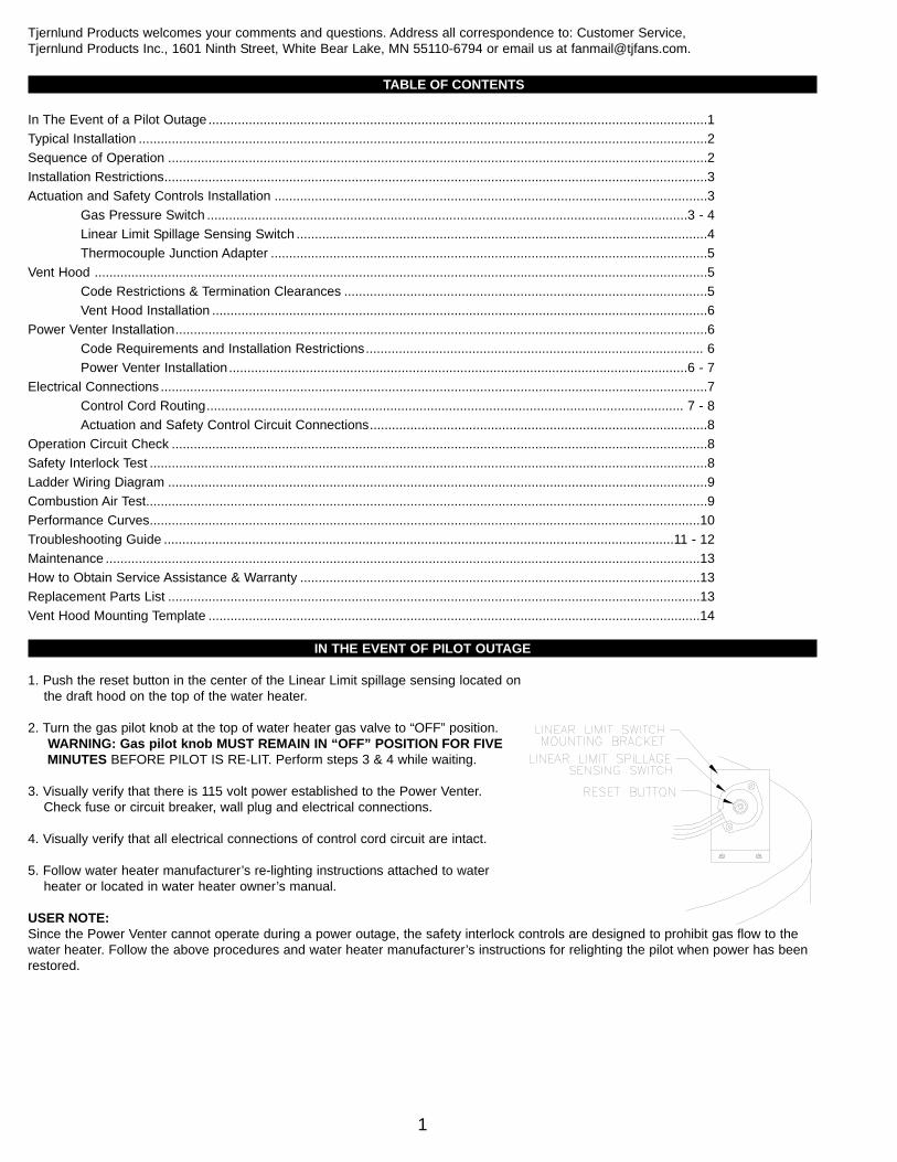
IN THE EVENT OF PILOT OUTAGE
1. Push the reset button in the center of the Linear Limit spillage sensing located on the draft hood on the top of the water heater.
2. Turn the gas pilot knob at the top of water heater gas valve to “OFF” position.WARNING: Gas pilot knob MUST REMAIN IN “OFF” POSITION FOR FIVEMINUTES BEFORE PILOT IS RE-LIT. Perform steps 3 & 4 while waiting.
3. Visually verify that there is 115 volt power established to the Power Venter.Check fuse or circuit breaker, wall plug and electrical connections.
4. Visually verify that all electrical connections of control cord circuit are intact.
5. Follow water heater manufacturer’s re-lighting instructions attached to water heater or located in water heater owner’s manual.
USER NOTE:Since the Power Venter cannot operate during a power outage, the safety interlock controls are designed to prohibit gas flow to thewater heater. Follow the above procedures and water heater manufacturer’s instructions for relighting the pilot when power has beenrestored.
1
INSTALLER NOTES
1. The installer must read and follow these instructions carefully to assure proper installation and operation of the water heater vent package.
2. The installer must fill in the required information on the nameplate located on the Power Venter electrical box.
3. The installer must affix the wiring diagram label included with these instructions to the water heater casing adjacent toits rating plate.
4. The water heater may only be installed on the suction side of Power Venter.
5. The installer must notify the owner of the maintenance (Page 13) required with the use of this product.
6. The installer must verify that the pilot safety controls on water heater are in good operating condition before installation of the water heater vent package.
7. The Power Venter must not be installed into any portion of a vent system which serves appliances other than the one(s) vented by the VP-2F or VP-3F.
SEQUENCE OF OPERATION
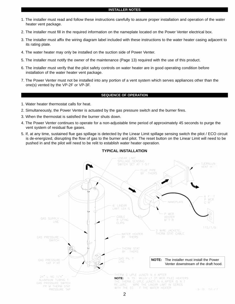
1. Water heater thermostat calls for heat.2. Simultaneously, the Power Venter is actuated by the gas pressure switch and the burner fires.3. When the thermostat is satisfied the burner shuts down.4. The Power Venter continues to operate for a non-adjustable time period of approximately 45 seconds to purge the
vent system of residual flue gases.5. If, at any time, sustained flue gas spillage is detected by the Linear Limit spillage sensing switch the pilot / ECO circuit
is de-energized, disrupting the flow of gas to the burner and pilot. The reset button on the Linear Limit will need to be pushed in and the pilot will need to be relit to establish water heater operation.
TYPICAL INSTALLATION
2
NOTE:
NOTE: The installer must install the Power Venter downstream of the draft hood.
3
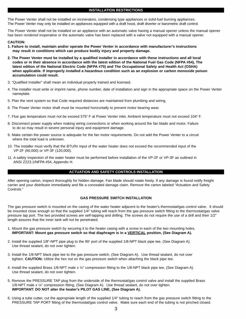
INSTALLATION RESTRICTIONS
The Power Venter shall not be installed on incinerators, condensing type appliances or solid-fuel burning appliances. The Power Venter may only be installed on appliances equipped with a draft hood, draft diverter or barometric draft control.
The Power Venter shall not be installed on an appliance with an automatic valve having a manual opener unless the manual openerhas been rendered inoperative or the automatic valve has been replaced with a valve not equipped with a manual opener.
CAUTION:1. Failure to install, maintain and/or operate the Power Venter in accordance with manufacturer’s instructions
may result in conditions which can produce bodily injury and property damage.
2. The Power Venter must be installed by a qualified installer in accordance with these instructions and all local codes or in their absence in accordance with the latest edition of the National Fuel Gas Code (NFPA #54), The latest edition of the National Electric Code (NFPA #70) and The Occupational Safety and Health Act (OSHA) when applicable. If improperly installed a hazardous condition such as an explosion or carbon monoxide poison accumulation could result.
3. “Qualified Installer” shall mean an individual properly trained and licensed.
4. The installer must write or imprint name, phone number, date of installation and sign in the appropriate space on the Power Venter nameplate.
5. Plan the vent system so that Code required distances are maintained from plumbing and wiring.
6. The Power Venter motor shaft must be mounted horizontally to prevent motor bearing wear.
7. Flue gas temperature must not be exceed 5750 F at Power Venter inlet. Ambient temperature must not exceed 1040 F.
8. Disconnect power supply when making wiring connections or when working around the fan blade and motor. Failure to do so may result in severe personal injury and equipment damage.
9. Make certain the power source is adequate for the fan motor requirements. Do not add the Power Venter to a circuit where the total load is unknown.
10. The installer must verify that the BTU/hr input of the water heater does not exceed the recommended input of the VP-2F (60,000) or VP-3F (120,000).
11. A safety inspection of the water heater must be performed before installation of the VP-2F or VP-3F as outlined in ANSI Z223.1/NFPA #54, Appendix H.
ACTUATION AND SAFETY CONTROLS INSTALLATION
After opening carton, inspect thoroughly for hidden damage. Fan blade should rotate freely. If any damage is found notify freightcarrier and your distributor immediately and file a concealed damage claim. Remove the carton labeled “Actuation and SafetyControls.”
GAS PRESSURE SWITCH INSTALLATION
The gas pressure switch is mounted on the casing of the water heater adjacent to the heater's thermostat/gas control valve. It shouldbe mounted close enough so that the supplied 1/4" tubing will reach from the gas pressure switch fitting to the thermostat/gas valvepressure tap port. The two provided screws are self-tapping and drilling. The screws do not require the use of a drill and their 1/2"length assures that the inner tank will not be penetrated.
1. Mount the gas pressure switch by securing it to the heater casing with a screw in each of the two mounting holes. IMPORTANT: Mount gas pressure switch so that diaphragm is in a VERTICAL position, (See Diagram A).
2. Install the supplied 1/8"-NPT pipe plug to the 90o port of the supplied 1/8-NPT black pipe tee, (See Diagram A). Use thread sealant, do not over tighten.
3. Install the 1/8-NPT black pipe tee to the gas pressure switch, (See Diagram A). Use thread sealant, do not over tighten. CAUTION: Utilize the hex nut on the gas pressure switch when attaching the black pipe tee.
4. Install the supplied Brass 1/8-NPT male x ¼" compression fitting to the 1/8-NPT black pipe tee, (See Diagram A). Use thread sealant, do not over tighten.
5. Remove the PRESSURE TAP plug from the underside of the thermostat/gas control valve and install the supplied Brass 1/8-NPT male x ¼" compression fitting, (See Diagram A). Use thread sealant, do not over tighten.IMPORTANT: DO NOT alter the heater's PILOT GAS LINE, (See Diagram A).
6. Using a tube cutter, cut the appropriate length of the supplied 1/4" tubing to reach from the gas pressure switch fitting to the PRESSURE TAP PORT fitting of the thermostat/gas control valve. Make sure each end of the tubing is not pinched closed.
4
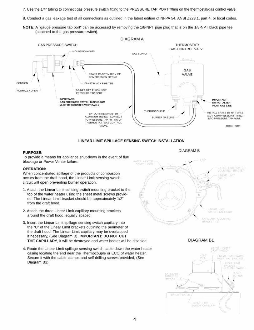
7. Use the 1/4" tubing to connect gas pressure switch fitting to the PRESSURE TAP PORT fitting on the thermostat/gas control valve.
8. Conduct a gas leakage test of all connections as outlined in the latest edition of NFPA 54, ANSI Z223.1, part 4. or local codes.
NOTE: A "gauge pressure tap port" can be accessed by removing the 1/8-NPT pipe plug that is on the 1/8-NPT black pipe tee (attached to the gas pressure switch).VE
NT HOOD TERMINATION CLEALINEAR LIMIT SPILLAGE SENSING SWITCH INSTALLATION
PURPOSE:To provide a means for appliance shut-down in the event of flueblockage or Power Venter failure.
OPERATION:When concentrated spillage of the products of combustionoccurs from the draft hood, the Linear Limit sensing switch circuit will open preventing burner operation.
1. Attach the Linear Limit sensing switch mounting bracket to thetop of the water heater using the sheet metal screws provid-ed. The Linear Limit bracket should be approximately 1/2” from the draft hood.
2. Attach the three Linear Limit capillary mounting brackets around the draft hood, equally spaced.
3. Insert the Linear Limit spillage sensing switch capillary into the “U” of the Linear Limit brackets outlining the perimeter of the draft hood. The Linear Limit capillary may be overlapped if necessary, (See Diagram B). IMPORTANT: DO NOT CUTTHE CAPILLARY, it will be destroyed and water heater will be disabled.
4. Route the Linear Limit spillage sensing switch cable down the water heater casing locating the end near the Thermocouple or ECO of water heater. Secure it with the cable clamps and self drilling screws provided, (See Diagram B1).
DIAGRAM B
DO NOT ALTER
GAS SUPPLY
INTO PRESSURE TAP PORT.
GAS PRESSURE SWITCHGAS CONTROL VALVE
THERMOSTAT/
PILOT GAS LINE
8050011 7/18/07
INSTALL BRASS 1/8-NPT MALEx 1/4" COMPRESSION FITTING
THERMOCOUPLE
BURNER GAS LINE
COMMON
MUST BE MOUNTED VERTICALLY.GAS PRESSURE SWITCH DIAPHRAGMIMPORTANT:
BRASS 1/8-NPT MALE x 1/4"COMPRESSION FITTING
THERMOSTAT / GAS CONTROLTO PRESSURE TAP FITTING OF
1/4" OUTSIDE DIAMETERALUMINUM TUBING - CONNECT
VALVE.
1/8-NPT BLACK PIPE TEE
1/8-NPT PIPE PLUG - NEWPRESSURE TAP PORT
NORMALLY OPEN
MOUNTING HOLES
IMPORTANT:
GASVALVE
DIAGRAM A
DIAGRAM B1
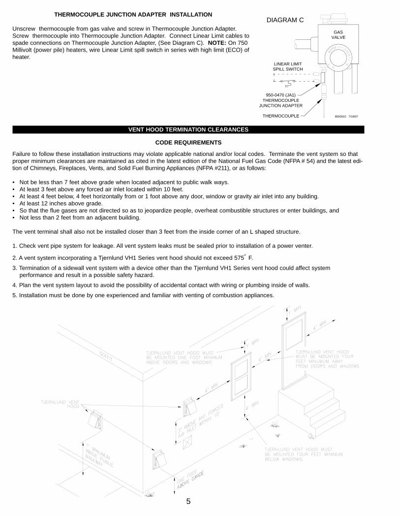
THERMOCOUPLE JUNCTION ADAPTER INSTALLATION
Unscrew thermocouple from gas valve and screw in Thermocouple Junction Adapter.Screw thermocouple into Thermocouple Junction Adapter. Connect Linear Limit cables tospade connections on Thermocouple Junction Adapter, (See Diagram C). NOTE: On 750Millivolt (power pile) heaters, wire Linear Limit spill switch in series with high limit (ECO) ofheater.
VENT HOOD TERMINATION CLEARANCES
CODE REQUIREMENTS
Failure to follow these installation instructions may violate applicable national and/or local codes. Terminate the vent system so thatproper minimum clearances are maintained as cited in the latest edition of the National Fuel Gas Code (NFPA # 54) and the latest edi-tion of Chimneys, Fireplaces, Vents, and Solid Fuel Burning Appliances (NFPA #211), or as follows:
• Not be less than 7 feet above grade when located adjacent to public walk ways.• At least 3 feet above any forced air inlet located within 10 feet.• At least 4 feet below, 4 feet horizontally from or 1 foot above any door, window or gravity air inlet into any building. • At least 12 inches above grade.• So that the flue gases are not directed so as to jeopardize people, overheat combustible structures or enter buildings, and• Not less than 2 feet from an adjacent building.
The vent terminal shall also not be installed closer than 3 feet from the inside corner of an L shaped structure.
1. Check vent pipe system for leakage. All vent system leaks must be sealed prior to installation of a power venter.
2. A vent system incorporating a Tjernlund VH1 Series vent hood should not exceed 575o
F.
3. Termination of a sidewall vent system with a device other than the Tjernlund VH1 Series vent hood could affect system performance and result in a possible safety hazard.
4. Plan the vent system layout to avoid the possibility of accidental contact with wiring or plumbing inside of walls.
5. Installation must be done by one experienced and familiar with venting of combustion appliances.
5
JUNCTION ADAPTERTHERMOCOUPLE
950-0470 (JA1)
LINEAR LIMITSPILL SWITCH
GASVALVE
THERMOCOUPLE 8050010 7/18/07
DIAGRAM C
VENT HOOD INSTALLATION
1. Verify that proposed Vent Hood location will conform to “Vent Hood Termination Clearances” on page 5.
2. Use scissors to detach Vent Hood Mounting Template on page 14. Follow instructions on Vent Hood template.
POWER VENTER INSTALLATION
CODE REQUIREMENTS
Power Venter installation must be in accordance with the following requirements of the National Fuel Gas Code: (ANSI Z223.1)
• All portions of the vent system under positive pressure during operation (on the outlet side of the Power Venter) shall be designed and installed so as to prevent leakage of flue or vent gases into a building.
• All appliances must enter the vent system on the inlet side of the Power Venter.
• Provision shall be made to interlock the appliance(s) to prevent the flow of gas to the main burners when the draft system is not performing so as to satisfy the operating requirements of the equipment for safe performance.
INSTALLATION RESTRICTIONS
1. Power Venter should be installed as close to the termination of the vent system as possible to prevent flue gas leakage.
2. Power Venter must be installed with the motor shaft horizontal to prevent motor bearing wear.
3. Power Venter housing is single wall. Six inch clearance must be maintained to combustible materials.
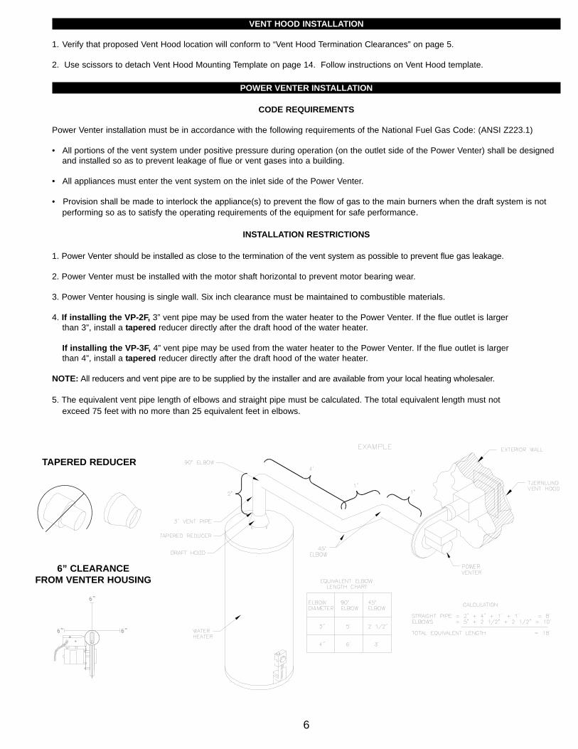
4. If installing the VP-2F, 3” vent pipe may be used from the water heater to the Power Venter. If the flue outlet is larger than 3”, install a tapered reducer directly after the draft hood of the water heater.
If installing the VP-3F, 4” vent pipe may be used from the water heater to the Power Venter. If the flue outlet is larger than 4”, install a tapered reducer directly after the draft hood of the water heater.
NOTE: All reducers and vent pipe are to be supplied by the installer and are available from your local heating wholesaler.
5. The equivalent vent pipe length of elbows and straight pipe must be calculated. The total equivalent length must not exceed 75 feet with no more than 25 equivalent feet in elbows.
6
6” CLEARANCEFROM VENTER HOUSING
TAPERED REDUCER
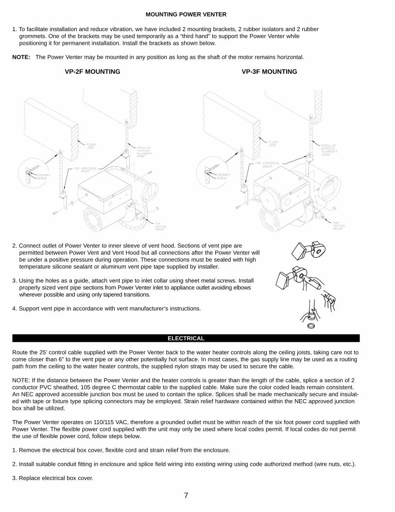
MOUNTING POWER VENTER
1. To facilitate installation and reduce vibration, we have included 2 mounting brackets, 2 rubber isolators and 2 rubber grommets. One of the brackets may be used temporarily as a “third hand” to support the Power Venter while positioning it for permanent installation. Install the brackets as shown below.
NOTE: The Power Venter may be mounted in any position as long as the shaft of the motor remains horizontal.
2. Connect outlet of Power Venter to inner sleeve of vent hood. Sections of vent pipe are permitted between Power Vent and Vent Hood but all connections after the Power Venter will be under a positive pressure during operation. These connections must be sealed with hightemperature silicone sealant or aluminum vent pipe tape supplied by installer.
3. Using the holes as a guide, attach vent pipe to inlet collar using sheet metal screws. Install properly sized vent pipe sections from Power Venter inlet to appliance outlet avoiding elbows wherever possible and using only tapered transitions.
4. Support vent pipe in accordance with vent manufacturer’s instructions.
ELECTRICAL
Route the 25’ control cable supplied with the Power Venter back to the water heater controls along the ceiling joists, taking care not tocome closer than 6” to the vent pipe or any other potentially hot surface. In most cases, the gas supply line may be used as a routingpath from the ceiling to the water heater controls, the supplied nylon straps may be used to secure the cable.
NOTE: If the distance between the Power Venter and the heater controls is greater than the length of the cable, splice a section of 2conductor PVC sheathed, 105 degree C thermostat cable to the supplied cable. Make sure the color coded leads remain consistent.An NEC approved accessible junction box must be used to contain the splice. Splices shall be made mechanically secure and insulat-ed with tape or fixture type splicing connectors may be employed. Strain relief hardware contained within the NEC approved junctionbox shall be utilized.
The Power Venter operates on 110/115 VAC, therefore a grounded outlet must be within reach of the six foot power cord supplied withPower Venter. The flexible power cord supplied with the unit may only be used where local codes permit. If local codes do not permitthe use of flexible power cord, follow steps below.
1. Remove the electrical box cover, flexible cord and strain relief from the enclosure.
2. Install suitable conduit fitting in enclosure and splice field wiring into existing wiring using code authorized method (wire nuts, etc.).
3. Replace electrical box cover.
7
VP-2F MOUNTING VP-3F MOUNTING
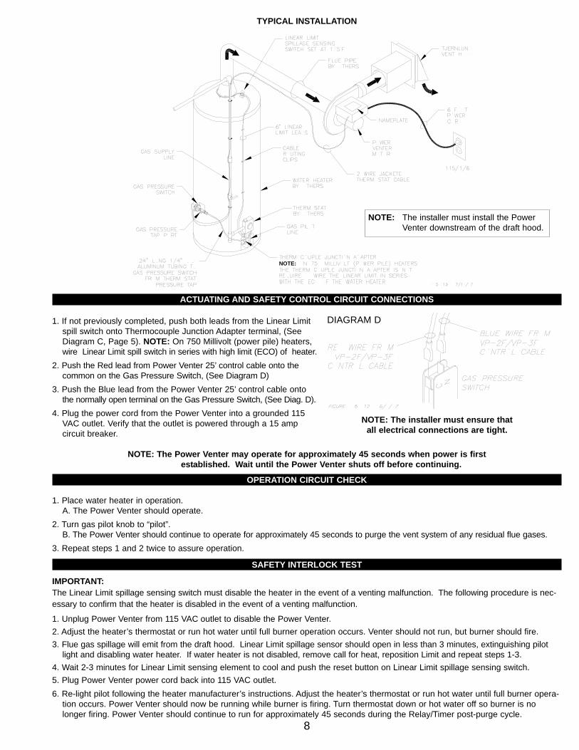
ACTUATING AND SAFETY CONTROL CIRCUIT CONNECTIONS
1. If not previously completed, push both leads from the Linear Limit spill switch onto Thermocouple Junction Adapter terminal, (See Diagram C, Page 5). NOTE: On 750 Millivolt (power pile) heaters, wire Linear Limit spill switch in series with high limit (ECO) of heater.
2. Push the Red lead from Power Venter 25’ control cable onto the common on the Gas Pressure Switch, (See Diagram D)
3. Push the Blue lead from the Power Venter 25’ control cable onto the normally open terminal on the Gas Pressure Switch, (See Diag. D).
4. Plug the power cord from the Power Venter into a grounded 115 VAC outlet. Verify that the outlet is powered through a 15 amp circuit breaker.
NOTE: The Power Venter may operate for approximately 45 seconds when power is firstestablished. Wait until the Power Venter shuts off before continuing.
OPERATION CIRCUIT CHECK
1. Place water heater in operation.A. The Power Venter should operate.
2. Turn gas pilot knob to “pilot”.B. The Power Venter should continue to operate for approximately 45 seconds to purge the vent system of any residual flue gases.
3. Repeat steps 1 and 2 twice to assure operation.
SAFETY INTERLOCK TEST
IMPORTANT: The Linear Limit spillage sensing switch must disable the heater in the event of a venting malfunction. The following procedure is nec-essary to confirm that the heater is disabled in the event of a venting malfunction.
1. Unplug Power Venter from 115 VAC outlet to disable the Power Venter.2. Adjust the heater’s thermostat or run hot water until full burner operation occurs. Venter should not run, but burner should fire.3. Flue gas spillage will emit from the draft hood. Linear Limit spillage sensor should open in less than 3 minutes, extinguishing pilot
light and disabling water heater. If water heater is not disabled, remove call for heat, reposition Limit and repeat steps 1-3. 4. Wait 2-3 minutes for Linear Limit sensing element to cool and push the reset button on Linear Limit spillage sensing switch.5. Plug Power Venter power cord back into 115 VAC outlet.6. Re-light pilot following the heater manufacturer’s instructions. Adjust the heater’s thermostat or run hot water until full burner opera-
tion occurs. Power Venter should now be running while burner is firing. Turn thermostat down or hot water off so burner is no longer firing. Power Venter should continue to run for approximately 45 seconds during the Relay/Timer post-purge cycle.
8
NOTE: The installer must ensure that all electrical connections are tight.
NOTE:
TYPICAL INSTALLATION
DIAGRAM D
NOTE: The installer must install the Power Venter downstream of the draft hood.

VP-2F / VP-3F WATER HEATER VENT PACKAGE LADDER WIRING DIAGRAM
COMBUSTION AIR TEST
WARNING:The Linear Limit spillage sensing switch is designed to alert the user to a potentially hazardous condition. It is not designed to, and can-not replace, regular vent system inspection, appliance servicing and combustion testing. DO NOT USE IT AS A SUBSTITUTE FORPROFESSIONAL APPLIANCE MAINTENANCE.1. Close all doors and windows of the building. If the appliance is installed in a utility room or closet, close the entrance door. Close fire
place dampers.
2. Turn on clothes dryer. Turn on all exhaust fans, such as range hoods, bathroom exhaust and whole house fans to maximum speeds. Do not operate a fan used strictly for summer exhausting.
3. Following the water heater manufacturer’s instructions, place the appliance in operation, set thermostat for continuous operation.
4. Allow fans and appliance to operate for 5 minutes.
5. Tripping of the Linear Limit spillage sensing switch during the 5 minutes indicates an unsafe operating condition. Turn off fuel supply to appliance and DO NOT OPERATE UNTIL UNSAFE VENTING CONDITION IS INVESTIGATED BY PROFESSIONALCONTRACTOR OR UTILITY SERVICE PERSONNEL.
6. Return all windows, doors and fans to their previous conditions of use.
7. Sign and date these instructions to verify that the Sign: combustion air and safety interlock test have beencompleted. These instructions must remain on premises. Date:
9
WHITEBLACK
WHITE
WHITEBLACK
MOTORTIMER RELAY
115 / 1 / 60PLUG
YELLOWRED
4 5
TIMER RELAYRED BLUE
TRANSFORMER115V
24V
THERMOCOUPLE
PRESSURESWITCH
GAS
JUNCTION ADAPTER
BLACK BLACKBLACK
BLACK
LINEAR LIMITSPILLAGE SENSING SWITCH
(185°F MANUAL RESET)
COM N / O
OR ECO OF WATERHEATER
6/4/07FIGURE 8075001
GREEN
POWER VENTER
BLACK WHITE
24V LOW VOLTAGE FACTORY WIRING
115V LINE VOLTAGE FACTORY WIRING
DENOTES HEATING APPLIANCE MILLIVOLTCIRCUIT (THERMOCOUPLE OR ECO)
LEGEND:
DENOTES QUICK CONNECT
DENOTES WIRE NUT
L1 L2 M
GREEN

PERFORMANCE CURVES
10
VP-2F PERFORMANCE CURVE
VP-3F PERFORMANCE CURVE
VP-2F / VP-3F TROUBLESHOOTING GUIDE
11
Note: For further assistance contact
Solution
Step 6
Solution
Step 5
Solution
Step 4
Solution
Step 3
Step 2
Step 1
Symptom 1
at 1-800-255-4208, 7:30 - 4:30 CST.Technical Customer Service Department
the Tjernlund Products, Inc.
Yes
No
Yes
No Blockage
Yes, Leakage
No
Yes
No
Yes
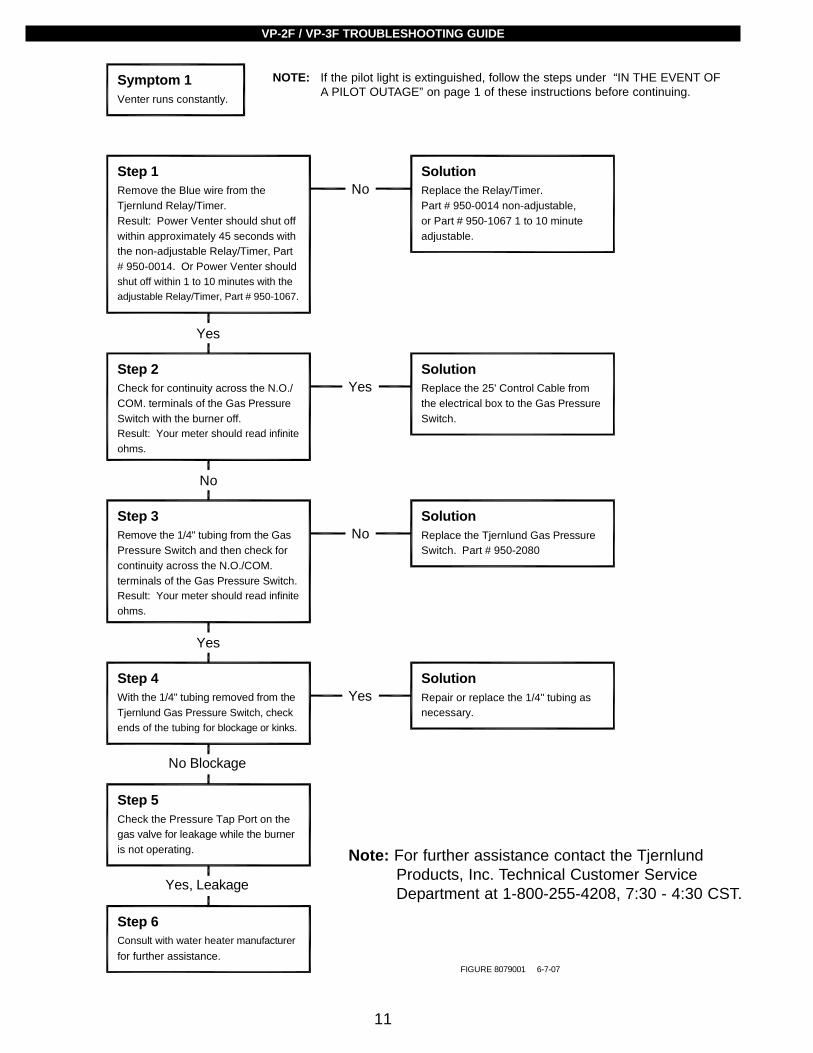
Venter runs constantly.
Remove the Blue wire from the Tjernlund Relay/Timer.
# 950-0014. Or Power Venter shouldshut off within 1 to 10 minutes with theadjustable Relay/Timer, Part # 950-1067.
Result: Power Venter should shut offwithin approximately 45 seconds withthe non-adjustable Relay/Timer, Part
Check for continuity across the N.O./COM. terminals of the Gas Pressure Switch with the burner off.Result: Your meter should read infinite
Remove the 1/4" tubing from the GasPressure Switch and then check for continuity across the N.O./COM. terminals of the Gas Pressure Switch.Result: Your meter should read infinite
With the 1/4" tubing removed from the Tjernlund Gas Pressure Switch, check ends of the tubing for blockage or kinks.
Check the Pressure Tap Port on thegas valve for leakage while the burneris not operating.
Consult with water heater manufacturer for further assistance.
Replace the Relay/Timer.Part # 950-0014 non-adjustable,or Part # 950-1067 1 to 10 minute
Replace the 25' Control Cable fromthe electrical box to the Gas PressureSwitch.
Replace the Tjernlund Gas PressureSwitch. Part # 950-2080
Repair or replace the 1/4" tubing as necessary.
ohms.
ohms.
adjustable.
FIGURE 8079001 6-7-07
Note: For further assistance contact the Tjernlund Products, Inc. Technical Customer Service Department at 1-800-255-4208, 7:30 - 4:30 CST.
NOTE: If the pilot light is extinguished, follow the steps under “IN THE EVENT OF A PILOT OUTAGE” on page 1 of these instructions before continuing.

12
Note: For further assistance contact
Step 3.2
Step 6
Step 3.1
Step 5
Solution
Step 4
Solution
Step 3
Step 2
Step 1
Symptom 2
at 1-800-255-4208, 7:30 - 4:30 CST.Technical Customer Service Department
the Tjernlund Products, Inc.
Yes
Yes
Yes
No Blockage
No
No
YesNo
Yes
Venter will not run.
Establish that all 115 volt circuits arecomplete to the Power Venter. Checkthe electrical plug to the wall receptacle,circuit breakers, and fuses.
CAUTION: Disconnect the 115 voltpower supply to the Power Venter be-fore attempting the following procedure.a) Remove the two Black leads from
Remove the 1/4" tubing from theTjernlund Gas Pressure Switch andcheck ends of the tubing for blockage
Check for gas pressure at the PressureTap Port on the gas valve while theburner is operating.
Consult with water heater manufacturer for further assistance.
Re-establish 115 volts to the PowerVenter.
Replace the Power Venter motor.Motor Part NumberVP-2F 950-2020
Measure the voltage on terminals 4and 5 on the Relay/Timer.
Measure the voltage on the secondaryside of the 115/24 volt transformer.
the Relay/Timer and connect them
8079002 7-18-07
Solution
Part # 950-0014 non-adjustable,Replace the Relay/Timer.
or Part # 950-1067 one to ten minute
No
VP-3F 950-1020
together.
supply to the Power Venter.b) Re-establish the 115 volt power
Result: The Power Venter should runconstantly.
Result: At this time you should measureapproximately 24 volts.
No
Replace the 25' Control Cable fromthe electrical box to the Gas Pressure
Yes
Switch.
Solution
Replace the Transformer.
No
Solution
Part # 950-2030
Result: At this time you should measureapproximately 24 volts.
Result: The Power Venter should run
the Gas Pressure Switch.b) Jump the Red and Blue leads from Step 2 to their original terminals.a) Reinstall the two Black leads fromfore attempting the following procedure.power supply to the Power Venter be-CAUTION: Disconnect the 115 volt
constantly.
supply to the Power Venter.c) Re-establish the 115 volt power
Repair or replace the 1/4" tubing asnecessary.
Solution
Replace the Tjernlund Gas Pressure
Yes,
Switch. Part # 950-2080
Solution
or kinks.
Result: Pressure is present.
Blockage
adjustable.
Note: For further assistance contact the Tjernlund Products, Inc. Technical Customer Service Department at 1-800-255-4208, 7:30 - 4:30 CST.
NOTE: If the pilot light is extinguished, follow the steps under “IN THE EVENT OF A PILOT OUTAGE” on page 1 of these instructions before continuing.
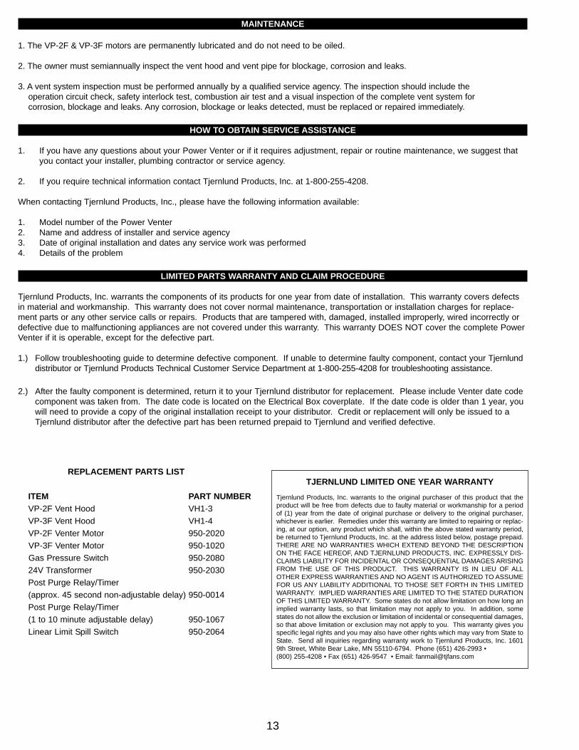
MAINTENANCE
1. The VP-2F & VP-3F motors are permanently lubricated and do not need to be oiled.
2. The owner must semiannually inspect the vent hood and vent pipe for blockage, corrosion and leaks.
3. A vent system inspection must be performed annually by a qualified service agency. The inspection should include the operation circuit check, safety interlock test, combustion air test and a visual inspection of the complete vent system for corrosion, blockage and leaks. Any corrosion, blockage or leaks detected, must be replaced or repaired immediately.
HOW TO OBTAIN SERVICE ASSISTANCE
1. If you have any questions about your Power Venter or if it requires adjustment, repair or routine maintenance, we suggest thatyou contact your installer, plumbing contractor or service agency.
2. If you require technical information contact Tjernlund Products, Inc. at 1-800-255-4208.
When contacting Tjernlund Products, Inc., please have the following information available:
1. Model number of the Power Venter 2. Name and address of installer and service agency3. Date of original installation and dates any service work was performed4. Details of the problem
LIMITED PARTS WARRANTY AND CLAIM PROCEDURE
Tjernlund Products, Inc. warrants the components of its products for one year from date of installation. This warranty covers defectsin material and workmanship. This warranty does not cover normal maintenance, transportation or installation charges for replace-ment parts or any other service calls or repairs. Products that are tampered with, damaged, installed improperly, wired incorrectly ordefective due to malfunctioning appliances are not covered under this warranty. This warranty DOES NOT cover the complete PowerVenter if it is operable, except for the defective part.
1.) Follow troubleshooting guide to determine defective component. If unable to determine faulty component, contact your Tjernlund distributor or Tjernlund Products Technical Customer Service Department at 1-800-255-4208 for troubleshooting assistance.
2.) After the faulty component is determined, return it to your Tjernlund distributor for replacement. Please include Venter date code component was taken from. The date code is located on the Electrical Box coverplate. If the date code is older than 1 year, you will need to provide a copy of the original installation receipt to your distributor. Credit or replacement will only be issued to a Tjernlund distributor after the defective part has been returned prepaid to Tjernlund and verified defective.
13
REPLACEMENT PARTS LIST
ITEM PART NUMBERVP-2F Vent Hood VH1-3VP-3F Vent Hood VH1-4 VP-2F Venter Motor 950-2020VP-3F Venter Motor 950-1020Gas Pressure Switch 950-208024V Transformer 950-2030Post Purge Relay/Timer(approx. 45 second non-adjustable delay) 950-0014Post Purge Relay/Timer(1 to 10 minute adjustable delay) 950-1067Linear Limit Spill Switch 950-2064
TJERNLUND LIMITED ONE YEAR WARRANTY
Tjernlund Products, Inc. warrants to the original purchaser of this product that theproduct will be free from defects due to faulty material or workmanship for a periodof (1) year from the date of original purchase or delivery to the original purchaser,whichever is earlier. Remedies under this warranty are limited to repairing or replac-ing, at our option, any product which shall, within the above stated warranty period,be returned to Tjernlund Products, Inc. at the address listed below, postage prepaid.THERE ARE NO WARRANTIES WHICH EXTEND BEYOND THE DESCRIPTIONON THE FACE HEREOF, AND TJERNLUND PRODUCTS, INC. EXPRESSLY DIS-CLAIMS LIABILITY FOR INCIDENTAL OR CONSEQUENTIAL DAMAGES ARISINGFROM THE USE OF THIS PRODUCT. THIS WARRANTY IS IN LIEU OF ALLOTHER EXPRESS WARRANTIES AND NO AGENT IS AUTHORIZED TO ASSUMEFOR US ANY LIABILITY ADDITIONAL TO THOSE SET FORTH IN THIS LIMITEDWARRANTY. IMPLIED WARRANTIES ARE LIMITED TO THE STATED DURATIONOF THIS LIMITED WARRANTY. Some states do not allow limitation on how long animplied warranty lasts, so that limitation may not apply to you. In addition, somestates do not allow the exclusion or limitation of incidental or consequential damages,so that above limitation or exclusion may not apply to you. This warranty gives youspecific legal rights and you may also have other rights which may vary from State toState. Send all inquiries regarding warranty work to Tjernlund Products, Inc. 16019th Street, White Bear Lake, MN 55110-6794. Phone (651) 426-2993 • (800) 255-4208 • Fax (651) 426-9547 • Email: [email protected]
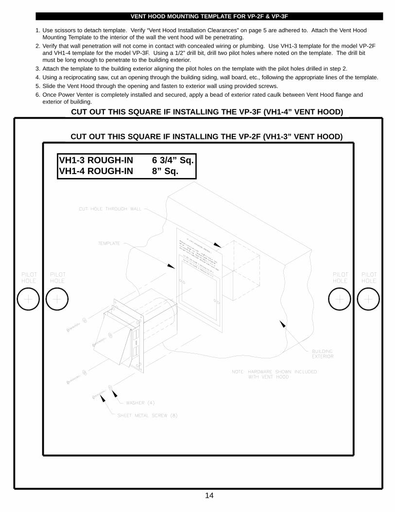
VENT HOOD MOUNTING TEMPLATE FOR VP-2F & VP-3F
1. Use scissors to detach template. Verify “Vent Hood Installation Clearances” on page 5 are adhered to. Attach the Vent Hood Mounting Template to the interior of the wall the vent hood will be penetrating.
2. Verify that wall penetration will not come in contact with concealed wiring or plumbing. Use VH1-3 template for the model VP-2F and VH1-4 template for the model VP-3F. Using a 1/2” drill bit, drill two pilot holes where noted on the template. The drill bit must be long enough to penetrate to the building exterior.
3. Attach the template to the building exterior aligning the pilot holes on the template with the pilot holes drilled in step 2.4. Using a reciprocating saw, cut an opening through the building siding, wall board, etc., following the appropriate lines of the template.5. Slide the Vent Hood through the opening and fasten to exterior wall using provided screws.6. Once Power Venter is completely installed and secured, apply a bead of exterior rated caulk between Vent Hood flange and
exterior of building.
14
CUT OUT THIS SQUARE IF INSTALLING THE VP-3F (VH1-4” VENT HOOD)
CUT OUT THIS SQUARE IF INSTALLING THE VP-2F (VH1-3” VENT HOOD)
VH1-3 ROUGH-IN 6 3/4” Sq.VH1-4 ROUGH-IN 8” Sq.